

Page 1

YASKAWA
VARISPEED-616G5
INSTRUCTION MANUAL
MULTI-FUNCTION ALL-DIGITAL TYPE (VS-616G5)
MODEL: CIMR-G5A
SPEC: F
200V CLASS 0.4 to 75kW (1.2 to 110kVA)
400V CLASS 0.4 to 300kW (1.4 to 460kVA)
Upon receipt of the product and prior to initial operation, read these instructions
thoroughly, and retain for future reference.
YA S K A WA
MANUAL NO. TOE-S616-10.30
Page 2

Preface
Preface
The VARISPEED-616G5 Series of general-purpose Inverters provides V/f control and vector con-
trol as standard features along with user-friendly operation.
This manual is designed to ensure correct and suitable application of VARISPEED-616G5-series
Inverters. Read this manual before attempting to install, operate, maintain, or inspect an Inverter and
keep it in a safe, convenient location for future reference. Be sure you understand all precautions
and safety information before attempting application.
i
Page 3
Safety Information
The following conventions are used to indicate precautions in this manual. Failure to heed precautions provided
in this manual can result in serious or possibly even fatal injury or damage to the products or to related equipment
and systems.
WARNING
!
Indicates precautions that, if not heeded, could possibly result in loss of life or
serious injury.
CAUTION Indicates precautions that, if not heeded, could result in relatively serious or minor
!
injury, damage to the product, or faulty operation.
The warning symbols for ISO and JIS standards are different, as shown below.
ISO JIS
The ISO symbol is used in this manual.
Both of thesesymbolsappearonwarninglabels on Yaskawaproducts. Please abide by thesewarninglabelsregard-
less of which symbol is used.
Yaskawa, 1998
All rights reserved. No part of this publication may be reproduced, stored in a retrieval system, or transmitted,
in any form, or by any means, mechanical, electronic, photocopying, recording, or otherwise, without the prior
written permission of Yaskawa. No patent liability is assumed with respect to the use of the information contained
herein. Moreover, because Yaskawa is constantly striving to improve its high-quality products, the information
contained in this manual is subject to change without notice. Every precaution has been taken in the preparation
of this manual. Nevertheless, Yaskawa assumes no responsibility for errors or omissions. Neither is any liability
assumed for damages resulting from the use of the information contained in this publication.
ii
Page 4

Visual Aids
The following aids are used to indicate certain types of information for easier reference.
Visual Aids
A
EXAMPLE
INFO
IMPORTANT
"
Indicates application examples.
Indicates supplemental information.
Indicates important information that should be memorized.
iii
Page 5

General Precautions
D The diagrams in this manual may be indicated without covers or safety shields to show de-
tails. Be sure to restore covers or shields before operating the Units and run the Units according to the instructions described in this manual.
D Any illustrations, photographs, or examples used in this manual are provided as examples
only and may not apply to all products to which this manual is applicable.
D The products and specifications described in this manual or the content and presentation
of the manual may be changed without notice to improve the product and/or the manual.
D When ordering a new copy of the manual due to damage or loss, contact your Yaskawa rep-
resentatives or the nearest Yaskawa sales office and provide the manual number shown on
the front cover.
D If nameplates become warn or damaged, order new ones from your Yaskawa representa-
tives or the nearest Yaskawa sales office.
iv
Page 6

Safety Precautions
Confirmations upon Delivery
J
D Never install an Inverter that is damaged or missing components.
Doing so can result in injury.
J Installation
D Always hold the case when carrying the Inverter.
If theInverterisheldbythefrontcover,the main body of the Inverter may fall, possibly resulting in injury.
D Attach the Inverter to a metal or other noncombustible material.
Fire can result if the Inverter is attached to a combustible material.
D Install a cooling fan or other cooling device when installing more than one Inverter in
the same enclosure so that the temperature of the air entering the Inverters is below
45_C.
Overheating can result in fires or other accidents.
Safety Precautions
CAUTION
Page
2-2
CAUTION
Page
2-6
2-6
2-6
J Wiring
WARNING
D Always turn OFF the input power supply before wiring terminals.
Otherwise, an electric shock or fire can occur.
D Wiring must be performed by an authorized person qualified in electrical work.
Otherwise, an electric shock or fire can occur.
D Be sure to ground the ground terminal.
(200 V class: Ground to 100 Ω or less, 400 V class: Ground to 10 Ω or less)
Otherwise, an electric shock or fire can occur.
D Always check the operation of any emergency stop circuits after they are wired.
Otherwise, there is the possibility of injury. (Wiring is the responsibility of the user.)
D Never touch the output terminals directly with your hands or allow the output lines to
come into contact with the Inverter case. Never short the output circuits.
Otherwise, electric shock or grounding can occur.
CAUTION
D Check to be sure that the voltage of the main AC power supply satisfies the rated
voltage of the Inverter.
Injury or fire can occur if the voltage is not correct.
D Do not perform voltage withstand tests on the Inverter.
Otherwise, semiconductor elements and other devices can be damaged.
D Connect braking resistors, Braking Resistor Units, and Braking Units as shown in the
I/O wiring examples.
Otherwise, a fire can occur.
D Tighten all terminal screws to the specified tightening torque.
Otherwise, a fire may occur.
Page
3-2
3-2
3-2
3-2
3-2
Page
3-2
3-2
3-2
3-2
v
Page 7
D Do not connect AC power to output terminals U, V, and W.
The interior parts of the Inverter will be damaged if voltage is applied to the output terminals.
D Do not connect phase-advancing capacitors or LC/RC noise filters to the output cir-
cuits.
The Inverter can be damaged or internal parts burnt if these devices are connected.
D Do not connect electromagnetic switches or contactors to the output circuits.
If a load is connected while the Inverter is operating, surge current will cause the overcurrent
protection circuit inside the Inverter to operate.
J Setting User Constants
D Disconnect the load (machine, device) from the motor before autotuning.
The motor may turn, possibly resulting in injury or damage to equipment. Also, motor
constants cannot be correctly set with the motor attached to a load.
J Trial Operation
D Check to be sure that the front cover is attached before turning ON the power supply.
Do not remove the front cover during operation.
An electric shock may occur.
D Do not come close to the machine when the fault reset function is used. If the alarmed
is cleared, the machine may start moving suddenly.
Also, design the machine so that human safety is ensured even when it is restarted.
Injury may occur.
D Provide a separate emergency stop switch; the Digital Operator STOP Key is valid
only when its function is set.
Injury may occur.
D Reset alarms only after confirming that the RUN signal is OFF.Ifanalarmis reset with
the RUN signal turned ON, the machine may suddenly start.
Injury may occur.
CAUTION
Page
3-2
3-2
3-2
CAUTION
Page
4-30
WARNING
Page
5-2
5-2
5-2
5-2
CAUTION
D Don’t touch the radiation fins (heat sink), braking resistor, or Braking Resistor Unit.
These can become very hot.
Otherwise, a burn injury may occur.
D Be sure that the motor and machine is within the applicable ranges before starting
operation.
Otherwise, an injury may occur.
D Provide a separate holding brake if necessary.
Always construct the external sequence to confirm that the holding brake is activated
in the event of an emergency,a power failure, or an abnormality in the inverter occuring.
Failure to observe this caution can result in personal injury.
D If using with an elevator, take safety measures on the machine’s side to prevent the
elevator from dropping.
Failure to observe this caution can result in personal injury.
vi
Page
5-2
5-2
5-2
5-2
Page 8
CAUTION
Safety Precautions
D Don’t check signals while the Inverter is running.
Otherwise, the equipment may be damaged.
D Be careful when changing Inverter settings. The Inverter is factory set to suitable set-
tings.
Otherwise, the equipment may be damaged. You must, however, you must set the power supply voltage jumper for 400 V class Inverters of 18.5 kW or higher (see 5.2.4).
J Maintenance and Inspection
D Do not touch the Inverter terminals. Some of the terminals carry high voltages and
are extremely dangerous.
Doing so can result in electric shock.
D Always have the protective cover in place when power is being supplied to the Invert-
er. When attaching the cover, always turn OFF power to the Inverter through the
MCCB.
Doing so can result in electric shock.
D After turning OFF the main circuit power supply, wait until the CHARGE indicator light
goes out before performing maintenance or inspections.
The capacitor will remain charged and is dangerous.
D Maintenance, inspection, and replacement of parts must be performed only by au-
thorized personnel.
Remove all metal objects, such as watches and rings, before starting work. Always
use grounded tools.
Failure to heed these warning can result in electric shock.
5-2
5-2
WARNING
Page
10-2
10-2
10-2
10-2
J Other
CAUTION
Page
D A CMOS IC is used in the control board. Handle the control board and CMOS IC care-
fully.
The CMOS IC can be destroyed by static electricity if touched directly.
D Do not change the wiring, or remove connectors or the Digital Operator, during op-
eration.
Doing so can result in personal injury.
10-2
10-2
WARNING
D Do not attempt to modify or alter the Inverter.
Doing so can result in electric shock or injury.
CAUTION
D Do not subject the Inverter to halogen gases, such as fluorine, chlorine, bromine, and iodine, at
any time even during transportation or installation.
Otherwise, the Inverter can be damaged or interior parts burnt.
vii
Page 9
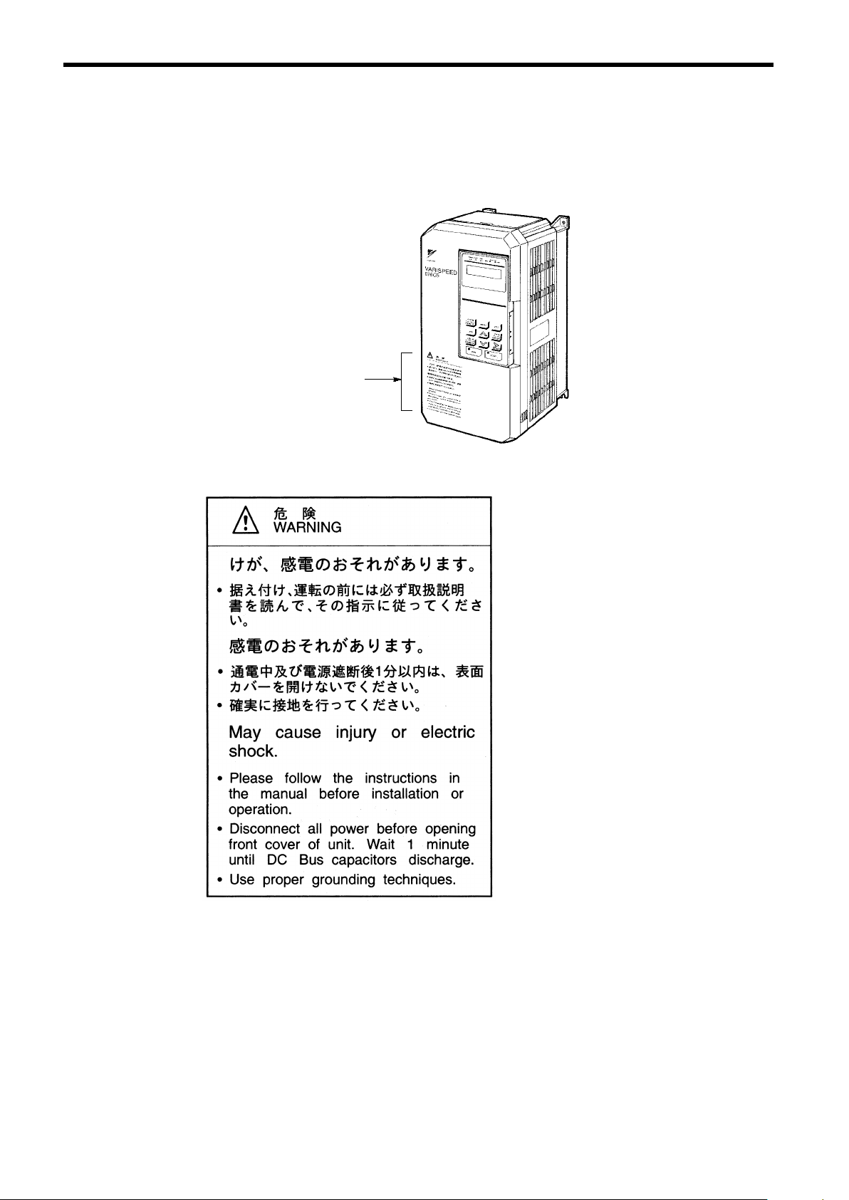
Warning Label Contents and Position
There is a warning label on the Inverter in the position shown in the following illustration. Always heed the warnings given on this label.
Warning label
position
Illustration shows the CIMR-G5A23P7
Warning Label Contents
viii
Page 10
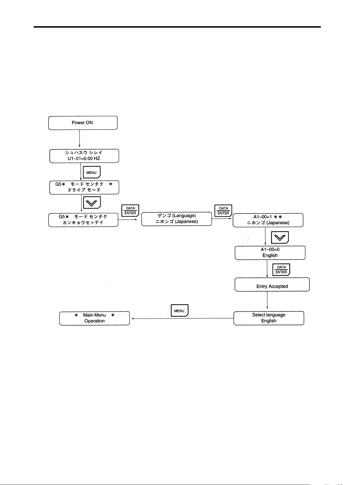
How to Change the Digital Operator Display from Japanese to English
How to Change the Digital Operator Display from Japanese to English
If the Digital Operator displays messages in Japanese, change to the English mode using the follow-
ing steps.
(This manual provides descriptions for the English mode.)
ix
Page 11

Warranty Information
J Free Warranty Period and Scope
Warranty Period
This product is warranted for twelve months after being delivered to Yaskawa’s customer or if appli-
cable eighteen months from the date of shipment from Yaskawa’s factory whichever comes first.
Scope of Warranty
Inspections
Periodic inspections must be conducted by the customer. However, upon request, Yaskawa or one
of Yaskawa’s Service Centers can inspect the product for a fee. In this case, if after conferring with
the customer, a Yaskawa product is found to be defective due to Yaskawa workmanship or materials
and the defect occurs during the warranty period, then this fee will be waived and the problem reme-
died free of charge.
Repairs
If a Yaskawa product is found to be defective due to Yaskawa workmanship or materials and the de-
fect occurs during the warranty period, Yaskawa will provide a replacement, repair the defective
product, and provide shipping to and from the site free of charge.
However, if the Yaskawa Authorized Service Center determines that the problem with a Yaskawa
product is not due to defects in Yaskawa’s workmanship or materials, then the customer will be re-
sponsible for the cost of any necessary repairs. Some problems that are outside the scope of this war-
ranty are:
D Problems due to improper maintenance or handling, carelessness, or other reasons where
the customer is determined to be responsible.
D Problems due to additions or modifications made to a Yaskawa product without Yaskawa’s
understanding.
D Problems due to the use of a Yaskawa product under conditions that do not meet the recom-
mended specifications.
D Problems caused by natural disaster or fire.
D Or other problems not due to defects in Yaskawa workmanship or materials.
Warranty service is only applicable within Japan.
However, after−sales service is available for customers outside of Japan for a reasonable fee. Contact
your local Yaskawa representative for more information.
J Exceptions
Any inconvenience to the customer or damage to non−Yaskawa products due to Yaskawa’s defective
products whether within or outside the warranty period are NOT covered by this warranty.
x
Page 12
J Restrictions
D The Varispeed F7 was not designed or manufactured for use in devices or systems that may
directly affect or threaten human lives or health.
D Customers who intend to use the product described in this manual for devices or systems
relating to transportation, health care, space aviation, atomic or electric power, or underwater use must contact their Yaskawa representatives or the nearest Yaskawa sales office beforehand.
D This product has been manufactured under strict quality−control guidelines. However, if
this product is to be installed in any location where failure of this product could involve
or result in a life−and−death situation or loss of human life or in a facility where failure may
cause a serious accident or physical injury, safety devices must be installed to minimize
the likelihood of any accident.
Before Reading This Manual
Before Reading This Manual
This manual explains both the conventional VS-616G5 Inverters and the
G5-series Inverters for SPEC:F.
The shaded sections or those specified as being for SPEC:F apply only to
G5-series Inverters for SPEC:F ( Inverters with revised version letters of F or
later.)
Be certain to check the specification on the Inverter nameplate.
Example of Inverter Nameplate
Version code
MODEL : CIMR−G5A20P4 SPEC : 20P41F
INPUT : AC 3PH 200-220 V 50Hz
OUTPUT: AC 3PH 0-230 V 1.2kVA 3.2 A
LOT NO : MASS : 3.0kg
SER NO :
YASKAWA ELECTRIC CORPORATION
200-230 V 60Hz
JAPAN
xi
Page 13

CONTENTS
11 Introduction
12 Handling Inverters
13 Wiring
14 Setting User Constants
15 Trial Operation
16 Basic Operation
17 Advanced Operation
1
2
3
4
5
6
7
xiii
18 User Constants
19 Troubleshooting
10 Maintenance and Inspection
11 Specifications
12 Appendix
8
9
10
11
12
Page 14

Table of Contents
Table of Contents
Safety Information ii..................................................
Visual Aids iii........................................................
General Precautions iv................................................
Safety Precautions v.................................................
Warning Label Contents and Position viii.................................
How to Change the Digital Operator Display from Japanese to English ix....
Warranty Information x...............................................
Before Reading This Manual xi.........................................
1 Introduction 1 - 1........................................
1.1 Outline and Functions 1 - 2........................................
1.1.1 VS-616G5 Inverter Models 1 - 2............................................
1.1.2 Outline of Control Methods 1 - 4............................................
1.1.3 Functions 1-4...........................................................
1.2 Nomenclature 1 - 7...............................................
1.2.1 VS-616G5 Components 1 - 7...............................................
1.2.2 Digital Operator Components 1 - 8..........................................
2 Handling Inverters 2 - 1..................................
2.1 Confirmations upon Delivery 2 - 2..................................
2.1.1 Nameplate Information 2 - 2................................................
2.2 Exterior and Mounting Dimensions 2 - 4.............................
2.3 Checking and Controlling the Installation Site 2 - 6...................
2.3.1 Installation Site 2 - 6......................................................
2.3.2 Controlling the Ambient Temperature 2 - 6...................................
2.3.3 Protecting the Inverter from Foreign Matter 2 - 6..............................
2.4 Installation Orientation and Space 2 - 7.............................
2.5 Removing/Attaching the Digital Operator and Front Cover 2 - 8........
2.5.1 Inverters of 15 kW or Less 2 - 8............................................
2.5.2 Inverters of 18.5 kW or Higher 2 - 9.........................................
3 Wiring 3 - 1.............................................
3.1 Connections to Peripheral Devices 3 - 3............................
3.2 Connection Diagram 3 - 4.........................................
3.3 Terminal Block Configuration 3 - 5..................................
3.4 Wiring Main Circuit Terminals 3 - 6.................................
3.4.1 Applicable Wire Sizes and Closed-loop Connectors 3 - 6.......................
3.4.2 Main Circuit Terminal Functions 3 - 9........................................
3.4.3 Main Circuit Configurations 3 - 10............................................
3.4.4 Standard Connection Diagrams 3 - 12........................................
3.4.5 Wiring the Main Circuits 3 - 13...............................................
xv
Page 15

3.5 Wiring Control Circuit Terminals 3 - 20...............................
3.5.1 Wire Sizes and Closed-loop Connectors 3 - 20................................
3.5.2 Control Circuit Terminal Functions 3 - 21......................................
3.5.3 Control Circuit Terminal Connections (All Models) 3 - 22........................
3.5.4 Control Circuit Wiring Precautions 3 - 23......................................
3.6 Wiring Check 3 - 23...............................................
3.7 Installing and Wiring PG Speed Control Cards 3 - 24..................
3.7.1 Installing a PG Speed Control Card 3 - 24.....................................
3.7.2 PG Speed Control Card Terminal Blocks 3 - 25................................
3.7.3 Wiring a PG Speed Control Card 3 - 27.......................................
3.7.4 Wiring PG Speed Control Card Terminal Blocks 3 - 31..........................
3.7.5 Selecting the Number of PG (Encoder) Pulses 3 - 33...........................
4 Setting User Constants 4 - 1..............................
4.1 Using the Digital Operator 4 - 2....................................
4.2 Modes 4 - 5.....................................................
4.2.1 Inverter Modes 4 - 5......................................................
4.2.2 Switching Modes 4 - 6.....................................................
4.2.3 User Constant Access Levels 4 - 7..........................................
4.2.4 Operation Mode 4 - 12.....................................................
4.2.5 Initialize Mode 4 - 20.......................................................
4.2.6 Programming Mode 4 - 27..................................................
4.2.7 Autotuning Mode 4 - 31.....................................................
4.2.8 Modified Constants Mode 4 - 33.............................................
5 Trial Operation 5 - 1......................................
5.1 Procedure 5 - 3..................................................
5.2 Trial Operation Procedures 5 - 4...................................
5.2.1 Power ON 5-4...........................................................
5.2.2 Checking the Display Status 5 - 4...........................................
5.2.3 Initializing Constants 5 - 4.................................................
5.2.4 Setting Input Voltage 5 - 5.................................................
5.2.5 Autotuning 5 - 6..........................................................
5.2.6 No-load Operation 5 - 9...................................................
5.2.7 Loaded Operation 5 - 10....................................................
6 Basic Operation 6 - 1....................................
6.1 Common Settings 6 - 2...........................................
6.1.1 Setting the Access Level and Control Method: A1-01, A1-02 6 - 2...............
6.1.2 Frequency Reference Settings: b1-01, H3-01, H3-08, H3-09 6 - 4...............
6.1.3 Frequency Reference from Digital Operator: b1-01, o1-03, d1-01 to d1-09 6 - 7...
6.1.4 Run Source and Sequence Input Responsiveness: b1-02, b1-06, b1-07 6 - 9.....
6.1.5 Acceleration/Deceleration Times: C1-01 through C1-08, C1-09, C1-10, C1-11 6 - 10
6.1.6 Prohibiting Reverse Operation: b1-04 6 - 11...................................
6.1.7 Selecting the Stopping Method: b1-03 6 - 12..................................
6.1.8 Multi-function Input Settings: H1-01 through H1-06 6 - 13.......................
6.2 Open-loop Vector Control 6 - 18.....................................
6.2.1 Autotuning 6 - 18..........................................................
6.2.2 Autotuning Faults 6 - 19....................................................
6.3 V/f Control 6 - 21..................................................
6.3.1 Setting the Motor Constants: E1-01, E1-02, E2-01 6 - 21........................
6.3.2 V/f Pattern Selection: E1-03 6 - 22...........................................
xvi
Page 16

Table of Contents
6.4 Flux Vector Control 6 - 28..........................................
6.4.1 PG Speed Control Card Settings 6 - 28.......................................
6.4.2 Setting the Zero-speed Operation Constants 6 - 31.............................
6.4.3 Autotuning 6 - 33..........................................................
6.4.4 Speed Control (ASR) Structure 6 - 36........................................
6.4.5 Speed Control (ASR) Gain 6 - 38............................................
6.5 V/f Control with PG 6 - 40..........................................
6.5.1 Motor Constants: E1-01, E1-02, E2-01, E2-04 6-40..........................
6.5.2 V/f Pattern Selection: E1-03 6 - 41...........................................
6.5.3 PG Speed Control Card Settings 6 - 42.......................................
6.5.4 Speed Control (ASR) Structure 6 - 44........................................
6.5.5 Adjusting Speed Control (ASR) Gain 6 - 45....................................
7 Advanced Operation 7 - 1................................
7.1 Open-loop Vector Control 7 - 2.....................................
7.1.1 Torque Limit Function 7 - 4.................................................
7.1.2 Adjusting Speed Feedback 7 - 5............................................
7.1.3 Setting/Adjusting Motor Constants 7 - 6......................................
7.1.4 Operation Selection when Output Voltage Saturated 7 - 8......................
7.1.5 Starting Torque Compensation Function (for SPEC:F) 7 - 9.....................
7.2 V/f Control without PG 7 - 11.......................................
7.2.1 Energy-saving Control Function 7 - 13........................................
7.2.2 Hunting-prevention Function 7 - 13...........................................
7.2.3 Setting Motor Constants 7 - 14..............................................
7.3 Flux Vector Control 7 - 16..........................................
7.3.1 Droop Control Function 7 - 18...............................................
7.3.2 Zero-servo Function 7 - 19..................................................
7.3.3 Torque Control 7 - 21.......................................................
7.3.4 Speed/Torque Control Switching Function 7 - 27...............................
7.3.5 Torque Limit Function 7 - 30.................................................
7.3.6 Setting/Adjusting Motor Constants 7 - 31......................................
7.3.7 Operation Selection when Output Voltage Saturated 7 - 34......................
7.4 V/f Control with PG 7 - 36..........................................
7.4.1 Energy-saving Control Function 7 - 38........................................
7.4.2 Hunting-prevention Function 7 - 38...........................................
7.4.3 Setting Motor Constants 7 - 39...............................................
7.5 Common Functions 7 - 41..........................................
7.5.1 Application Constants: b 7 - 43..............................................
7.5.2 Tuning Constants: C 7 - 52..................................................
7.5.3 Reference Constants: d 7 - 57...............................................
7.5.4 Option Constants: F 7 - 59..................................................
7.5.5 External Terminal Functions: H 7 - 64.........................................
7.5.6 Protective Functions: L 7 - 84...............................................
7.5.7 Operator Constants: o 7 - 97................................................
8 User Constants 8 - 1.....................................
8.1 Initialize Mode Constants 8 - 3.....................................
8.2 Programming Mode Constants 8 - 5................................
8.2.1 Application Constants: b 8 - 5..............................................
8.2.2 Autotuning Constants: C 8 - 11..............................................
8.2.3 Reference Constants: d 8 - 17...............................................
8.2.4 Motor Constant Constants: E 8 - 20..........................................
8.2.5 Options Constants: F 8 - 24.................................................
xvii
Page 17

8.2.6 Terminal Constants: H 8 - 28................................................
8.2.7 Protection Constants: L 8 - 35...............................................
8.2.8 Operator Constants: o 8 - 43................................................
8.2.9 Factory Settings that Change with the Control Method (A1-02) 8 - 45.............
8.2.10 Factory Settings that Change with the Inverter Capacity (o2-04) 8 - 47...........
9 Troubleshooting 9 - 1....................................
9.1 Protective and Diagnostic Functions 9 - 2...........................
9.1.1 Fault Detection 9 - 2......................................................
9.1.2 Minor Fault Detection 9 - 6.................................................
9.1.3 Operation Errors 9 - 8.....................................................
9.2 Troubleshooting 9 - 9.............................................
9.2.1 If Constant Constants Cannot Be Set 9 - 9...................................
9.2.2 If the Motor Does Not Operate 9 - 9.........................................
9.2.3 If the Direction of the Motor Rotation is Reversed 9 - 11.........................
9.2.4 If the Motor Does Not Put Out Torque or If Acceleration is Slow 9 - 11.............
9.2.5 If the Motor Does Not Operate According to Reference 9 - 11....................
9.2.6 If the Slip Compensation Function Has Low Speed Precision 9 - 11...............
9.2.7 If There is Low Speed Control Accuracy at High-speed Rotation in Open-loop
9.2.8 If Motor Deceleration is Slow 9 - 12..........................................
9.2.9 If the Motor Overheats 9 - 12................................................
9.2.10 If There is Noise When the Inverter is Started or From an AM Radio 9 - 13.......
9.2.11 If the Ground Fault Interrupter Operates When the Inverter is Run 9 - 13.........
9.2.12 If There is Mechanical Oscillation 9 - 13.....................................
9.2.13 If the Motor Rotates Even When Inverter Output is Stopped 9 - 14...............
9.2.14 If 0 V is Detected When the Fan is Started, or Fan Stalls 9 - 14.................
9.2.15 If Output Frequency Does Not Rise to Frequency Reference 9 - 14..............
Vector Control Mode 9 - 11................................................
10 Maintenance and Inspection 10 - 1.........................
10.1 Maintenance and Inspection 10 - 3.................................
10.1.1 Daily Inspection 10 - 3....................................................
10.1.2 Periodic Inspection 10 - 3..................................................
10.1.3 Periodic Maintenance of Parts 10 - 3........................................
11 Specifications 11 - 1......................................
11.1 Standard Inverter Specifications 11 - 2..............................
11.2 Specifications of Options and Peripheral Devices 11 - 5...............
12 Appendix 12 - 1...........................................
12.1 Inverter Application Precautions 12 - 2..............................
12.1.1 Selection 12 - 2..........................................................
12.1.2 Installation 12 - 2........................................................
12.1.3 Settings 12 - 3...........................................................
12.1.4 Handling 12 - 3..........................................................
12.2 Motor Application Precautions 12 - 4...............................
12.2.1 Using the Inverter for an Existing Standard Motor 12 - 4.......................
12.2.2 Using the Inverter for Special Motors 12 - 5.................................
12.2.3 Power Transmission Mechanism (Speed Reducers, Belts, and Chains) 12 - 5....
12.3 Peripheral Device Application Precautions 12 - 6.....................
xviii
Page 18

12.4 Wiring Examples 12 - 8...........................................
12.4.1 Using a Braking Resistor Unit 12 - 8.........................................
12.4.2 Using a Braking Unit and Braking Resistor Unit 12 - 8..........................
12.4.3 Using Braking Units in Parallel 12 - 11........................................
12.4.4 Using a Braking Unit and Three Braking Resistor Units in Parallel 12 - 12..........
12.4.5 Using a JVOP-95-j, -96-j VS Operator 12 - 13...............................
12.4.6 Using an Open-collector Transistor for Operation Signals 12 - 14.................
12.4.7 Using Open-collector, Contact Outputs 12 - 14.................................
12.5 User Constants 12 - 15............................................
12.6 Function Block Diagram 12 - 20.....................................
INDEX
Table of Contents
xix
Page 19

1
Introduction
This chapter provides an overview of the VS-616G5 Inverter and describes
its functions and components.
1.1 Outline and Functions 1 - 2..................
1.1.1 VS-616G5 Inverter Models 1 - 2....................
1.1.2 Outline of Control Methods 1 - 4...................
1.1.3 Functions 1 - 4..................................
1.2 Nomenclature 1 - 7.........................
1.2.1 VS-616G5 Components 1 - 7......................
1.2.2 Digital Operator Components 1 - 8.................
1
1-1
Page 20
Introduction
Maximum
p
g
listedatthe
right
1.1.1 VS-616G5 Inverter Models
1.1 Outline and Functions
The VS-616G5 Inverters provides full-current vector control based on advanced control logic. An autotuning
function is included for easy vector control.
The Digital Operator provides a liquid crystal display that is 2 lines by 16 characters in size. User constant settings and monitor items are easily read in interactive operations in either Japanese or English. (The display language can be changed by setting a user constant.)
1
Voltage
Class
200 V class
1.1.1 VS-616G5 Inverter Models
VS-616G5 Inverters are available in 200 and 400 V class models. These are listed in the following table.
A total of 37 models is available for motor capacities of 0.4 to 300 kW.
Table 1.1 VS-616G5 Inverter Models
Maximum
Applicable
Motor Out-
put [kW]
0.4
0.75
1.5
2.2
3.7
5.5
7.5
11
15
18.5
22
30
37
45
55
75
Output Ca-
pacity [kVA]
1.2 CIMR-G5A20P4 20P41j *
2.3 CIMR-G5A20P7 20P71j *
3.0 CIMR-G5A21P5 21P51j *
4.2 CIMR-G5A22P2
6.7 CIMR-G5A23P7
9.5 CIMR-G5A25P5
13 CIMR-G5A27P5 27P51j *
19 CIMR-G5A2011 20111j *
24 CIMR-G5A2015 20151j *
30 CIMR-G5A2018 20180j * 20181j ‡
37 CIMR-G5A2022 20220j * 20221j ‡
50 CIMR-G5A2030 20300j † 20301j ‡
61 CIMR-G5A2037 20370j † 20371j ‡
70 CIMR-G5A2045 20450j † 20451j ‡
85 CIMR-G5A2055 20550j † 20551j ‡
110 CIMR-G5A2075 20750j ‡ 20751j ‡
VS-616G5
Model Number
(Specify all required standards when ordering.)
Open Chassis Type
(IEC IP 00)
CIMR-G5Ajjjjjj
Remove the top and bottom
covers from the models
listed at the ri
Inverter Specifications
ht.
.
*
Enclosed Wall-mounted
(IEC IP 20, NEMA 1)
CIMR-G5Ajjjjjj
Type
22P21j *
23P71j *
25P51j *
1-2
Page 21
1.1 Outline and Functions
p
g
listedatthe
right
Voltage
Voltage
Class
Class
400 V class
Maximum
Maximum
Applicable
Applicable
Motor Out-
Motor Out-
put [kW]
put [kW]
0.4
0.75
1.5
2.2
3.7
5.5
7.5
11
15
18.5
22
30
37
45
55
75
110
160
185
220
300
VS-616G5
Output Ca-
pacity [kVA]
1.4 CIMR-G5A40P4 40P41j *
2.6 CIMR-G5A40P7 40P71j *
3.7 CIMR-G5A41P5 41P51j *
4.7 CIMR-G5A42P2
6.1 CIMR-G5A43P7
11 CIMR-G5A45P5
14 CIMR-G5A47P5 47P51j *
21 CIMR-G5A4011 40111j *
26 CIMR-G5A4015 40151j *
31 CIMR-G5A4018 40180j * 40181j ‡
37 CIMR-G5A4022 40220j * 40221j ‡
50 CIMR-G5A4030 40300j * 40301j ‡
61 CIMR-G5A4037 40370j * 40371j ‡
73 CIMR-G5A4045 40450j * 40451j ‡
98 CIMR-G5A4055 40550j † 40551j ‡
130 CIMR-G5A4075 40750j † 40751j ‡
170 CIMR-G5A4110 41100j † 41101j ‡
230 CIMR-G5A4160 41600j † 41601j ‡
260 CIMR-G5A4185 41850j ‡
340 CIMR-G5A4220 42200j ‡
460 CIMR-G5A4300 43000j ‡
Model Number
(Specify all required standards when ordering.)
Open Chassis Type
(IEC IP 00)
CIMR-G5Ajjjjjj
Remove the top and bottom
covers from the models
listed at the ri
Inverter Specifications
ht.
.
*
Enclosed Wall-mounted
(IEC IP 20, NEMA 1)
CIMR-G5Ajjjjjj
Type
42P21j *
43P71j *
45P51j *
1
*: Immediate delivery †: Available from factory ‡: Manufactured upon order
1-3
Page 22
1
Introduction
1.1.2 Outline of Control Methods
1.1.2 Outline of Control Methods
The VS-616G5 uses four control methods.
Open-loop vector control (factory setting)
D
Flux vector control
D
V/f control without PG
D
V/f control with PG feedback
D
PG stands for pulse generator (encoder).
Vector control is a method for removing interference with magnetic flux and torque, and controlling torque
according to references.
Current vector control independently controls magnetic flux current and torque current by simultaneously
controlling the motor primary current and phases. This ensures smooth rotation, high torque, and accurate
speed/torque control at low speeds.
Vector control can be replaced by the conventional V/f control system. If the motor constants required for
vector control are not known, the motor constants can be automatically set with autotuning.
The control methods are effective for the following applications:
Open-loop vector control: General variable-speed drive.
D
Flux vector control: Simple servodrive, high-precision speed control/torque control.
D
V/f control without PG: Conventional Inverter control mode. Used for multi-drive operation
D
(connecting multiple motors to one Inverter).
V/f control with PG feedback:Simple speed feedback control. (For applications with the PG
D
connected to the machine shaft rather than the motor shaft.)
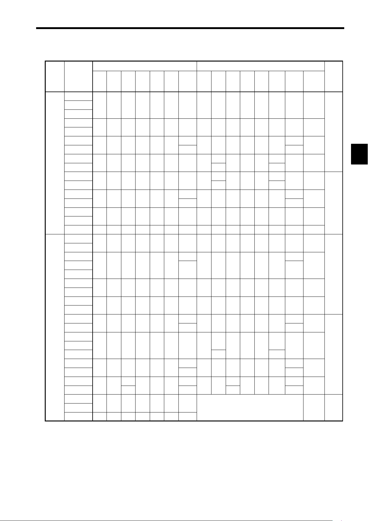
The control characteristics for each mode are shown in Table 1.2.
Table 1.2 Control Method Characteristics
1.1.3 Functions
J Autotuning
Autotuning is effective for vector control. It solves problems in applicable motor restrictions and difficult
constant settings. The motor constants are automatically set by entering a value from the motor’s rating
nameplate.
Autotuning allows flux vector control to operate accurately with virtually any normal AC induction motor,
regardless of the supplier.
Always autotune the motor separately before operating using vector control. Refer to 5.2.5 Autotuning and
6.4.3 Autotuning for details.
J Torque Control
Torque control is effective for flux vector control with PG. Torque is controlled by taking multi-function
analog input signals as torque references. Torque control accuracy is ±5%. Switching is possible between
torque control and speed control.
V/f Pattern Settings
J
V/f pattern settings are effective for V/f control. Select a V/f pattern according to the application from
among the 15 preset V/f patterns. Custom V/f patterns can also be set.
Characteristic
Speed Control
Range
Speed Control
Precision
Initial Drive
Vector Control V/f Control
Open-loop Flux Vector Without PG With PG feedback
1:100 1:1000 1:40 1:40
±0.2 % ±0.02 % ±2to3% ±0.03 %
150% at 1 Hz 150% at 0 r/min 150% at 3 Hz
J Frequency References
The following five types of frequency references can be used to control the output frequency of the Inverter.
Numeric input from the Digital Operator
D
Voltage input within a range from 0 to 10 V
D
Voltage input within a range from 0 to ±10 V (with negative voltages, rotation is in the opposite direc-
D
tion from the run command.)
1-4
Page 23

Current input within a range from 4 to 20 mA
D
Input from Option Card
D
Any of the above frequency references can be used by setting a constant.
A maximum of nine frequency references can be registered with the Inverter. With remote multi-step speed
reference inputs, the Inverter can operate in multi-step speed operation with a maximum of nine speed
steps.
PID Control
J
The Inverter has a PID control function for easy follow-up control. Follow-up control is a control method
in which the Inverter varies the output frequency to match the feedback value from the sensor for a set
target value.
Follow-up control can be applied to a variety of control operations, such as those listed below, depending
on the contents detected by the sensor.
Speed Control: With a speed sensor, such as a tacho-generator,the Inverter regulates the rotat-
D
Pressure Control: With a pressure sensor, the Inverter performs constant pressure control.
D
Flow-rate Control: By sensing the flow rate of a fluid, the Inverter performs precise flow-rate
D
Temperature Control: With a temperature sensor, the Inverter performs temperature control by fan
D
J Zero-servo Control
Zero-servo control is effective with flux vector control. Even at a motor speed of zero (r/min), a torque
of 150% of the motor’s rated torque can be generated and the average servomotor holding power (stopping
power) can be obtained.
1.1 Outline and Functions
1
ing speed of the motor regardless of the load of the motor or synchronizes the
rotating speed of the motor with that of another motor.
control.
speed.
Speed Control By Feedback
J
Speed control using feedback is effective with a PG. An optional PG Speed Control Card be used to enable
feedback control for speeds, thereby improving speed control accuracy.
J Dwell Function
By holding the output frequency for a constant time during acceleration and deceleration, acceleration and
deceleration can be performed without stepping out even when driving a motor with a large startup load.
J Low Noise
The output transistor of the Inverter is an IGBT (insulated gate bipolar transistor). Using sine-wave PWM
with a high-frequency carrier, the motor does not generate metallic noise.
J Monitor Function
The following items can be monitored with the Digital Operator: Frequency reference, output frequency,
output current, motor speed, output voltage reference, main-circuit DC voltage, output power, torque reference, status of input terminals, status of output terminals, operating status, total operating time, software
number, speed deviation value, PID feedback value, fault status, fault history, etc.
All types of data can be monitored even with multi-function analog output.
J Multilingual Digital Operator (SPEC:F)
The Digital Operator can display in seven languages (Japanese, English, German, French, Italian, Spanish,
and Portuguese). The Digital Operator’s liquid crystal display provides a 16-character x 2-line display
area.
Easy-to-read displays in each language allow the advanced functions of the Inverter to be set in interactive
operations to input constants, monitoring items, etc. Change the constant setting to select the display language.
J Harmonic Countermeasures (0.4 to 160 kW Models)
The VS-616G5 Inverters up to 160 kW support DC reactors to easily handle high-frequency control guidelines.
DC reactors (optional) can be connected to 0.4 to 15 kW models.
D
Models from 18.5 to 160 kW have a built-in DC reactor.
D
An optional AC reactor can be connected to Inverters from 185 to 300 kW.
D
1-5
Page 24
1
Introduction
1.1.3 Functions
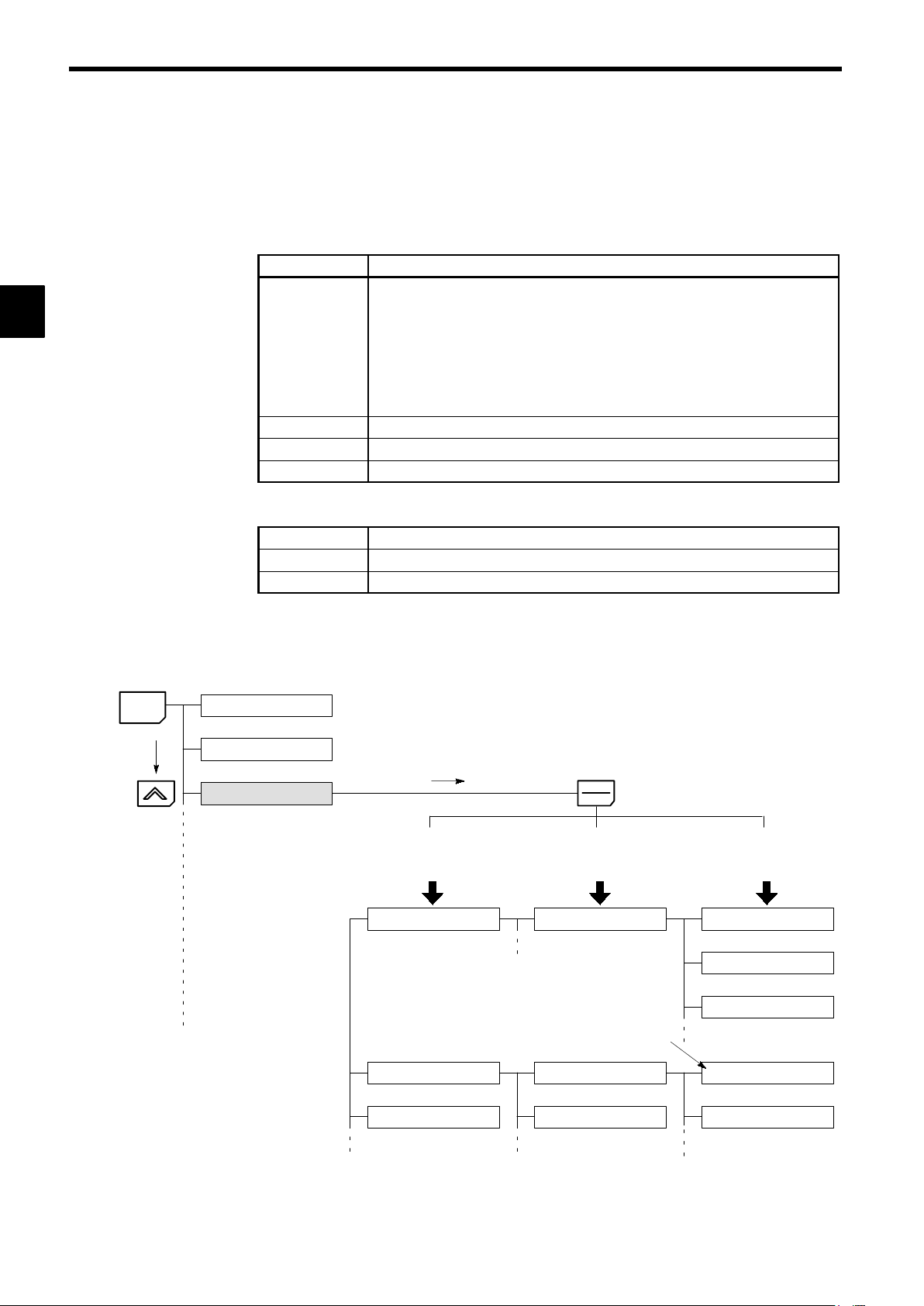
User Constant Structure and Three Access Levels
J
The VS-616G5 has a number of user constants for setting various functions. These user constants are classified into a hierarchy to make them easier to use.
The levels are as follows from top to bottom: Modes, Groups, Functions, and Constants. The access levels
for the user constants are shown in Table 1.3.
Table 1.3 Access Levels for User Constants
Level Contents
Mode
Groups
Functions
Constants
Classified according to operation
Operation: For operating the Inverter. (All kinds of monitoring are possible.)
Initialize: For selecting the language displayed at the Digital Operator, set-
ting access levels, initialization, and the control modes.
Programming: For setting user constants for operation.
Autotuning: For automatic calculation or setting motor constants. (Only under
the vector control mode.)
Modified constants: For referencing or changing user constants after shipping.
Classified by application.
Classified by function. (See user constants.)
Individual user constant settings.
The VS-616G5 allows the following three access levels to be set in order to further simplify setting user
constants. (An access level is a range of user constants that can be referenced or set.)
Quick-Start
Basic
Advanced
Reads/sets user constants required for trial operation. [Factory setting]
Reads/sets user constants that are commonly used.
Reads/sets all the user constants that can be used.
MENU
In general, press the DATA/ENTER Key to move from an upper to a lower level. This varies somewhat,
however, according to the access level, as shown in Fig. 1.1. For the Quick-Start access level, which has
few user constants that can be set, pressing the DATA/ENTER Key jumps directly to the user constant level; whereas for the Advanced access level, which has many user constants, pressing the DATA/ENTER
Key first leads to the Group level.
Operation mode
Initialize mode
Programming mode
DATA
ENTER
[Advanced] [Basic] [Quick-Start]
Displays group level.
Application
Displays function level.
b1 Sequence
Constant to be changed
Displays constant level.
b1-01 Reference source
b1-02 Run source
b1-03 Stopping method
Tuning
Reference
[Mode]
[Groups]
Fig 1.1 Access Level Structure
1-6
C1 Accel/Decel
C2 S-curve Acc/Dec
[Functions]
C1-01 Accel Time 1
C1-02 Decel Time 1
[Constants]
Page 25
1.2 Nomenclature
This section provides the names of VS-616G5 components, and the components and functions of the Digital
Operator.
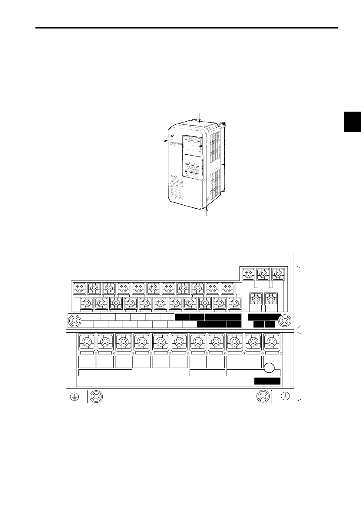
1.2.1 VS-616G5 Components
The appearance of Inverter and the names of its components are shown in Figure 1.2.
1.2 Nomenclature
Protective cover (top)
Mounting hole
Front cover
Digital Operator
JVOP-130
Die-cast case
Protective cover (bottom)
Fig 1.2 Appearance of VS-616G5, Model CIMR-G5A20P4 (200 V, 0.4 kW)
A 200 V Class Inverter with 0.4 kW Output is shown below with the front cover removed.
1
Control circuit
terminals
11 12(G) 13 14 15 16 17 25 26 27 33 18 19 20
1234567821 22 23 9
R
L1
S
Power input
L2
T
L3
¨1
©
¨2B1
Braking Resistor
B2
U
T1
Motor output
V
T2
10
W/T3
CHARGE
Fig 1.3 Terminal Arrangement
Main circuit
terminals
1-7
Page 26
Introduction
1.2.2 Digital Operator Components
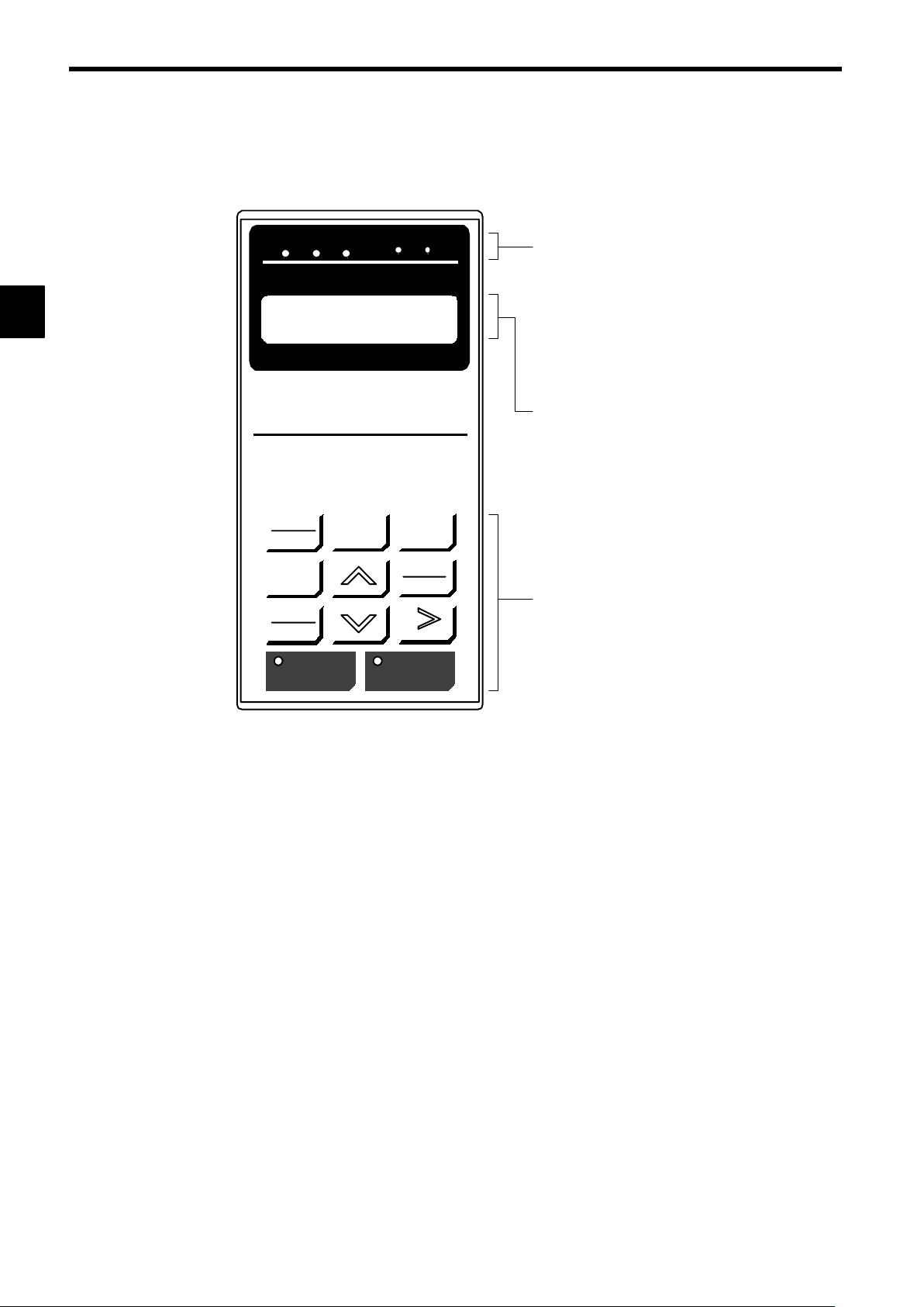
1.2.2 Digital Operator Components
This section describes the component names and functions of the Digital Operator. The component names
and functions are shown in Figure 1.4 and key functions are described in Table 1.4.
1
DRIVE FWD REV REMOTE
Frequency Ref
U1−01 = 00.00 HZ
DIGITAL OPERATOR
JVOP−130
LOCAL
REMOTE
JOG
FWD
REV
RUN STOP
SEQ REF
MENU
ESC
DATA
ENTER
RESET
Operation Mode Indicators
DRIVE: Lit when in operation mode.
FWD: Lit when there is a forward reference input.
REV: Lit when there is a reverse reference input.
SEQ: Lit when an operation reference from the
control circuit terminal is enabled.
REF: Lit when the frequency reference from con-
trol circuit terminals 13 and 14 is enabled.
Data Display
Two-line LCD that displays data for monitoring,
user constants, and set values with 16 characters
per line.
Keys
Execute operations such as setting user constants,
monitoring, jogging, and autotuning.
Fig 1.4 Digital Operator Component Names and Functions
1-8
Page 27
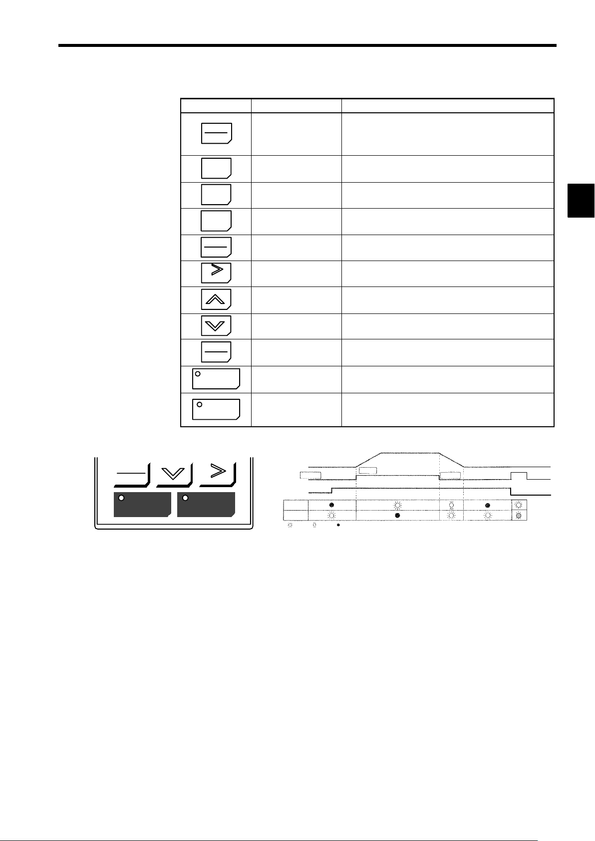
Table 1.4 Key Functions
Key Name Function
Switches between (LOCAL) operation via the Digital Operator
LOCAL
REMOTE
LOCAL/REMOTE Key
and control circuit terminal (REMOTE) operation.
This key can be enabled or disabled by setting a user constant
(o2-01).
1.2 Nomenclature
MENU
ESC
JOG
FWD
REV
RESET
DATA
ENTER
RUN
MENU Key Displays menus.
ESC Key
JOG Key
FWD/REV Key
RESET Key
Increment Key
Decrement Key
DATA/ENTER Key
RUN Key
Returns to the status before the DATA/ENTER Key was
pressed.
Enables jog operation when the VS-616G5 is being operated
from the Digital Operator.
Selects the rotation direction of the motor when the VS-616G5
is being operated from the Digital Operator.
Sets the number of digits for user constant settings.
Also acts as the reset key when a fault has occurred.
Selects menu items, groups, functions, and user constant
names, and increments set values.
Selects menu items, groups, functions, and user constant
names, and decrements set values.
Enters menu items, functions, constants, and set values after
they are set.
Starts the VS-616G5 operation when the VS-616G5 is in operation with the Digital Operator.
Stops VS-616G5 operation.
STOP
STOP Key
This key can be enabled or disabled by setting a user constant
(o2-02) when operating from the control circuit terminal.
Note Except in diagrams, keys are referred to using the key names listed in the above table.
1
FWD
REV
RUN STOP
RESET
Inverter output frequency
STOP
Frequency setting
RUN
OP
ST
:
:
Blinking:Not lit
Lit
RUN
The RUN and STOP indicators light and blink to indicate operating status.
During DB (initial excitation), RUN blinks and STOP is turned ON.
Fig 1.5 RUN and STOP Indicators
STOP
1-9
Page 28

2
Handling Inverters
This chapter describes the checks required upon receiving a VS-616G5 Inverter and describes installation methods.
2.1 Confirmations upon Delivery 2 - 2............
2.1.1 Nameplate Information 2 -
2.2 Exterior and Mounting Dimensions 2 - 4.......
2.3 Checking and Controlling the
Installation Site 2 - 6.......................
2.3.1 Installation Site 2 - 6..............................
2.3.2 Controlling the Ambient Temperature 2 - 6...........
2.3.3 Protecting the Inverter from Foreign Matter 2 - 6......
2.4 Installation Orientation and Space 2 - 7.......
2.5 Removing/Attaching the Digital Operator
and Front Cover 2 - 8......................
2.5.1 Inverters of 15 kW or Less 2 - 8....................
2.5.2 Inverters of 18.5 kW or Higher 2 - 9.................
.......................
2
2
2-1
Page 29

2
Handling Inverters
2.1.1 Nameplate Information
2.1 Confirmations upon Delivery
D Never install an Inverter that is damaged or missing components.
Doing so can result in injury.
Check the following items as soon as the Inverter is delivered.
Table 2.1 Checks
Item Method
Has the correct model of Inverter been
delivered?
Is the Inverter damaged in any way? Inspect the entire exterior of the Inverter to see if there are any scratches or
Are any screws or other components
loose?
If you find any irregularities in the above items, contact the agency from which you purchased the Inverter or
your Yaskawa representative immediately.
CAUTION
Check the model number on the nameplate on the side of the Inverter (See
2.1.1).
other damage resulting from shipping.
Use a screwdriver or other tools to check for tightness.
2.1.1 Nameplate Information
Example Nameplate
J
Standard domestic (Japan) Inverter: 3-phase, 200 VAC, 0.4 kW, IEC IP20 and NEMA 1 standards
Model number
Input specifications
Output specifications
Lot number
Serial number
J Inverter Model Numbers
Inverter
VS-616G5
No. Specification
A Standard domestic model
V UL/C-UL model
No. Voltage Class
2 AC input, 3-phase, 200 V
4 AC input, 3-phase, 400 V
D DC input, 3-phase, 200 V
E DC input, 3-phase, 400 V
MODEL : CIMR-G5A20P4 SPEC: 20P41F
INPUT : AC 3PH 200-220 V 50Hz
OUTPUT: AC 3PH 0-230 V 1.2kVA 3.2 A
LOT NO : MASS : 3.0kg
SER NO :
YASKAWA ELECTRIC CORPORATION
200-230 V 60Hz
JAPAN
CIMR -G5A 2 0P4
No. Max. Motor Capacity
0P4
0P7
to
075
“P” indicates the decimal point.
Inverter specifications
Mass
0.4 kW
0.75 kW
to
75kW
2-2
Page 30

Inverter Specifications
J
2.1 Confirmations upon Delivery
2 0P4 1 F
No. Voltage Class
2 AC input, 3-phase, 200 V
4 AC input, 3-phase, 400 V
D DC input, 3-phase, 200 V
E DC input, 3-phase, 400 V
No. Max. Motor Capacity
0P4
0P7
to
075
“P” indicates the decimal point.
Open Chassis Type (IEC IP00)
D
0.4 kW
0.75 kW
to
75kW
Protected so that parts of the human body cannot reach electrically charged parts from the front when
the Inverter is mounted in a control panel.
Enclosed Wall-mounted Type (IEC IP20, NEMA 1)
D
The Inverter is structured so that the Inverter is shielded from the exterior, and can thus be mounted
to the interior wall of a standard building (not necessarily enclosed in a control panel). The protective
structure conforms to the standards of NEMA 1 in the USA.
Version (Enter the specifications
form number when special specifications are required.)
No. Protective Structure
0
1
Enclosed wall-mounted (IEC IP20, NEMA 1)
Open chassis (IEC IP00)
2
2-3
Page 31

Handling Inverters
2.2 Exterior and Mounting Dimensions
200 V/400 V Class Inverters of 15 kW and Lower
J
The following diagram shows a 200 V class, 1.5 kW Inverter.
Remove the top and bottom covers when mounting 200 V/400 V class Inverters of 15 kW or lower in a
control panel.
2
H1
H
W1
W
200 V/400 V Class Inverters of 18.5 kW and Higher
J
H2
4-d
The following diagram shows a 200 V class, 18.5 kW Inverter.
H1
H
D
W1
W
H2
4-d
D
J Mounting Dimensions for 400 V Class Inverters of 185 to 300 kW
W5
W2 W3
W4
W6
W1
Max. Applicable Motor
Capacity
[kW]
185, 220
300
2-4
W1 W2 W3 W4 W5 W6
750 440 310 850 285 565
750 440 310 873 298 575
Page 32
Volt-
tion
200
V
in
tion
class
in
age
class
200 V
class
400 V
Max. Ap-
plicable
Motor Out-
put
[kW]
0.4
0.75
1.5
2.2
3.7
5.5
7.5
11
15
18.5
22
30
37
45
55
75
0.4
0.75
1.5
2.2
3.7
5.5
7.5
11
15
18.5
22
30
37
45
55
75
110
160
185
220
300
2.2 Exterior and Mounting Dimensions
Table 2.2 VS-616G5 External Dimensions (mm) and Approx. Masses (kg)
Open Chassis (IP00) Enclosed Wall-mounted (NEMA1)
W H D W1 H1 H2
Approx.
Mass
W H D W1 H1 H2
140 280 160 126 266 7.0 3 140 280 160 126 266 7.0 3 M5
140 280 180 126 266 7.0 4.5 140 280 180 126 266 7.0 4.5 M5
5.5
200 300 205 186 285 8.0
250 380 225 236 365 7.5 11 250
325 450 285 275 435 7.5 28 330
200 300 205 186 285 8.0
6
380
225 236 365
400
610
285 275 435
675
7.5
27.5
87.5
152.5
61
425 675 350 320 650 12.5
430 985 350 320 650 212.5
62
475 800 350 370 775 12.5 80 480 1110 350 370 775 212.5 87 M10
575 925 400 445 895 15.0 135 580 1290 400 445 895 270 145 M12
140 280 160 126 266 7.0 3 140 280 160 126 266 7.0 3 M5
4 4
140 280 180 126 266 7.0
140 280 180 126 266 7.0
4.5 4.5
200 300 205 186 285 8.0 6 200 300 205 186 285 8.0 6 M6
250 380 225 236 365 7.5 11 250 380 225 236 365 7.5 11 M6
29
325 450 285 275 435 7.5
325 625 285 275 610 7.5 44 330
330 610 285 275 435 87.5
31
785
285 275 610
87.5
850 152.5
81
455 820 350 350 795 12.5
375
575 925
445 895 15.0
400
950 1450 435 *21400 25 360
460 1130 350 350 795 212.5
82
135
145
580 1290
375
445 895 270
400
960 1600 455 *21550 25 420
Approx.
Mass
5.5
6
11 M6
32 M6
67
68
32
34
48 M6
87
88
145
155
Mounting
Holes
d*1
M6
M10
M5
M6
M10
M12
M12
DC
Reac-
*1
tor
Op-
Built-
Op-
Built-
2
* 1. Same for open chassis and enclosed wall-mounted types.
* 2. See page 2 - 4 for mounting dimensions.
Note An attachment is required to mount the cooling fins (fin section) on the outside of the control panel for 200 V/400 V class
Inverters of 15 kW or less. Please contact your Yaskawa representative for details. Dimensional drawings for models with
externally mounted cooling fins and other special requirements are also available from your Yaskawa representative.
2-5
Page 33

2
Handling Inverters
2.3.1 Installation Site
2.3 Checking and Controlling the Installation Site
CAUTION
D Always hold the case when carrying the Inverter.
If the Inverter is held by the front cover,the main body of the Inverter may fall, possibly resulting in injury.
D Attach the Inverter to a metal or other noncombustible material.
Fire can result if the Inverter is attached to a combustible material.
D Install a cooling fan or other cooling device when installing more than one Inverter in the same
enclosure so that the temperature of the air entering the Inverters is below 45_C.
Overheating can result in fires or other accidents.
Install the VS-616G5 in the installation site described below and maintain optimum conditions.
2.3.1 Installation Site
Install the Inverter under the following conditions.
Type Ambient Operating Temperature Humidity
Enclosed wallmounted
Open chassis
−10 to 40_C
−10 to 45_C 90% RH or less (no condensation)
90% RH or less (no condensation)
Protection covers are attached to the top and bottom of the Inverter. Be sure to remove the protection covers
before installing a 200 or 400 V Class Inverter with an output of 15 kW or less in a panel.
Install the Inverter in a clean location free from oil mist and dust. It can be installed in a totally enclosed
D
panel that is completely shielded from floating dust.
When installing or operating the Inverter, always take special care so that metal powder, oil, water, or
D
other foreign matter does not get into the Inverter.
Do not install the Inverter on combustible material, such as wood.
D
Install the Inverter in a location free from radioactive materials and combustible materials.
D
Install the Inverter in a location free from harmful gasses and liquids.
D
Install the Inverter in a location without excessive oscillation.
D
Install the Inverter in a location free from chlorides.
D
Install the Inverter in a location not in direct sunlight.
D
2.3.2 Controlling the Ambient Temperature
To enhance the reliability of operation, the Inverter should be installed in an environment free from extreme temperature increases. If the Inverter is installed in an enclosed environment, such as a box, use a
cooling fan or air conditioner to maintain the internal air temperature below 45°C.
2.3.3 Protecting the Inverter from Foreign Matter
Place a cover over the Inverter during installation to shield it from metal power produced by drilling.
Always remove the cover from the Inverter after completing installation. Otherwise, ventilation will be
reduced, causing the Inverter to overheat.
2-6
Page 34

2.4 Installation Orientation and Space
Install the Inverter on a vertical surface so as not to reduce the cooling effect. When installing the Inverter, always provide the following installation space to allow normal heat dissipation.
2.4 Installation Orientation and Space
IMPORTANT
50 mm min.
120 mm min.
30 mm min.30 mm min.
50 mm min.
(a) Horizontal Space
Fig 2.1 VS-616G5 Installation Orientation and Space
S The same space is required horizontally and vertically for both open chassis (IP00) and enclosed
wall-mounted (IP20, NEMA 1) Inverters.
S
Always remove the protection covers before installing a 200 or 400 V Class Inverter with an output
of 15 kW or less in a panel.
S
Always provide enough space for suspension eye bolts and the main circuit lines when installing a
200 or 400 V Class Inverter with an output of 30 kW or more in a panel.
120 mm min.
(b) Vertical Space
Air
Air
2
2-7
Page 35

Handling Inverters
2.5.1 Inverters of 15 kW or Less
2.5 Removing/Attaching the Digital Operator and Front Cover
Remove the front cover to wire the terminals.
For models of 15 kW or less (both 200 V and 400 V class), do not remove or mount the front cover without
first removing the Digital Operator; otherwise, the Digital Operator may malfunction due to imperfect contact.
Use the following procedures to remove or attach the front cover.
2.5.1 Inverters of 15 kW or Less
Removing the Digital Operator
J
Press the lever on the side of the Digital Operator in the direction of arrow 1 to unlock the Digital Operator
and lift the Digital Operator in the direction of arrow 2 to remove the Digital Operator as shown in the following illustration.
2
Front cover
Digital
Operator
Fig 2.2 Removing the Digital Operator
J Removing the Front Cover
Press the left and right sides of the front cover in the directions of arrows 1 and lift the bottom of the cover
in the direction of arrow 2 to remove the front cover as shown in the following illustration.
Front cover
1
2
2
1
Fig 2.3 Removing the Front Cover
J Mounting the Front Cover
After wiring the terminals, mount the front cover to the Inverter by performing in reverse order to the steps
to remove the front cover.
Do not mount the front cover with the Digital Operator attached to the front cover; otherwise, Digital
1.
Operator may malfunction due to imperfect contact.
Insert the tab of the upper part of the front cover into the groove of the Inverter and press the lower
2.
part of the front cover onto the Inverter until the front cover snaps shut.
1
2-8
Page 36

Mounting the Digital Operator
J
Hook the Digital Operator at A (two locations) on the front cover in the direction of arrow 1 as shown
1.
in the following illustration.
Press the Digital Operator in the direction of arrow 2 until it snaps in place at B (two locations).
2.
Digital
Operator
Front cover
2.5 Removing/Attaching the Digital Operator and Front Cover
2
1
A
2
B
Fig 2.4 Mounting the Digital Operator
IMPORTANT
1. Do not remove or attach the Digital Operator or mount or remove the front cover using methods other than
those described above, otherwise the Inverter may break or malfunction due to imperfect contact.
2. Never attach the front cover to the Inverter with the Digital Operator attached to the front cover. Imperfect
contact can result.
Always attach the front cover to the Inverter by itself first, and then attach the Digital Operator to the front
cover.
2.5.2 Inverters of 18.5 kW or Higher
The front cover can be removed without removing the Digital Operator from the Inverter provided that
the Inverter has an output of 18.5 kW or higher.
Loosen the four screws of the front cover and move the front cover slightly upwards to remove the front
cover.
2-9
Page 37

3
Wiring
This chapter describes wiring terminals, main circuit terminal connections,
main circuit terminal wiring specifications, control circuit terminals, and
control circuit wiring specifications.
3.1 Connections to Peripheral Devices 3 - 3......
3.2 Connection Diagram 3 - 4...................
3.3 Terminal Block Configuration 3 - 5............
3.4 Wiring Main Circuit Terminals 3 - 6...........
3.4.1 Applicable Wire Sizes and Closed-loop
Connectors 3 - 6...............................
3.4.2 Main Circuit Terminal Functions 3 - 9...............
3.4.3 Main Circuit Configurations 3 - 10...................
3.4.4 Standard Connection Diagrams 3 - 12...............
3.4.5 Wiring the Main Circuits 3 - 13......................
3
3.5 Wiring Control Circuit Terminals 3 - 20.........
3.5.1 Wire Sizes and Closed-loop Connectors 3 - 20........
3.5.2 Control Circuit Terminal Functions 3 - 21.............
3.5.3 Control Circuit Terminal Connections (All Models) 3 - 22
3.5.4 Control Circuit Wiring Precautions 3 - 23.............
3.6 Wiring Check 3 - 23.........................
3.7 Installing and Wiring PG Speed Control
Cards 3 - 24...............................
3.7.1 Installing a PG Speed Control Card 3 - 24............
3.7.2 PG Speed Control Card Terminal Blocks 3 - 25........
3.7.3 Wiring a PG Speed Control Card 3 - 27..............
3.7.4 Wiring PG Speed Control Card Terminal Blocks 3 - 31.
3.7.5 Selecting the Number of PG (Encoder) Pulses 3 - 33...
3-1
Page 38

3
Wiring
WARNING
D Always turn OFF the input power supply before wiring terminals.
Otherwise, an electric shock or fire can occur.
D Wiring must be performed by an authorized person qualified in electrical work.
Otherwise, an electric shock or fire can occur.
D Be sure to ground the ground terminal.
(200 V class: Ground to 100 Ω or less, 400 V class: Ground to 10 Ω or less)
Otherwise, an electric shock or fire can occur.
D Always check the operation of any emergency stop circuits after they are wired.
Otherwise, there is the possibility of injury. (Wiring is the responsibility of the user.)
D Never touch the output terminals directly with your hands or allow the output lines to come into
contact with the Inverter case. Never short the output circuits.
Otherwise, electrical shock or grounding can occur.
CAUTION
D Check to be sure that the voltage of the main AC power supply satisfies the rated voltage of the
Inverter.
Injury or fire can occur if the voltage is not correct.
D Do not perform voltage withstand tests on the Inverter.
Otherwise, semiconductor elements and other devices can be damaged.
D Connect braking resistors, Braking Resistor Units, and Braking Units as shown in the I/O wiring
examples.
Otherwise, a fire can occur.
D Tighten all terminal screws to the specified tightening torque.
Otherwise, a fire may occur.
D Do not connect AC power to output terminals U, V, and W.
The interior parts of the Inverter will be damaged if voltage is applied to the output terminals.
D Do not connect phase-advancing capacitors or LC/RC noise filters to the output circuits.
The Inverter can be damaged or internal parts burnt if these devices are connected.
D Do not connect electromagnetic switches or contactors to the output circuits.
If a load is connected while the Inverter is operating, surge current will cause the overcurrent protection
circuit inside the Inverter to operate.
3-2
Page 39

3.1 Connections to Peripheral Devices
Examples of connections between the VS-616G5 and typical peripheral devices are shown in Figure 3.1. Use
this illustration to gain an understanding of the overall equipment configuration.
Power supply
Molded-case circuit
breaker or ground
fault interrupter
Magnetic contactor
3.1 Connections to Peripheral Devices
3
AC reactor for power
factor improvement
Input noise filter
VS-616G5
Ground
DC reactor for power
factor improvement
Output noise filter
Motor
Ground
Fig 3.1 Example Connections to Peripheral Devices
3-3
Page 40

Wiring
3.2 Connection Diagram
The connection diagram of the VS-616G5 is shown in Figure 3.2.
When using the Digital Operator, the motor can be operated by wiring only the main circuits.
3
External
frequency
references
3-phase power
200 to 230 V
50/60 Hz
Factorypreset
functions
2kΩ
MCCB
R
S
T
Forward Run/Stop
Reverse Run/Stop
External fault
Fault reset
Multi-step speed setting 1
(Master/auxiliary switch)
Multi-step speed setting 2
Jog frequency reference
External baseblock command
2kΩ
0to10V
4to20mA
0to10V
0V
P
DC reactor to improve input
power factor (optional)
Short-circuit bar
P
P
¨ 1B1B2
¨ 2
©
R (L1)
S (L2)
T (L3)
VS-616G5
Forward run command
(forward when closed)
Reverse run command
(reverse when closed)
3
4
5
Multi-function contact
inputs
6
7
8
Sequence common
11
(Insulated from 0 V
terminal)
12 Shield wire connection terminal
15 Frequency setting power
15 V, 20 mA
13 Master speed reference
−10 to 10 V (20 kΩ)
(Default: 0 to 10 V/100%)
14 Master speed reference
4 to 20 mA (250 Ω)
16 Multi-function analog input
(−10 to 10 V (20 kΩ)
17
(Default: Auxiliary frequency
0V
33
Frequency setting
power:
−15 V, 20 mA
Analog
monitor 2
Analog
monitor 1
reference
0 to 10 V/100%)
Braking Resistor Unit (Optional)
U (T1)
V (T2)
W (T3)
23
21
22
(12)
18
19
20
9
10
25
26
27
Motor
IM
(Ground to 100 Ω max.)
AM
+
−
FM
Fault contact output
250 VAC, 1 A max.
30 VDC, 1 A max.
Multi-function contact output
250 VAC, 1 A max.
30 VDC, 1 A max.
(Default: Running signal)
Open collector 1
(Default: Zero speed
signal)
Open collector 2
(Default: Speed agree
signal)
Multi-function output
common
+
Multi-function analog output
−10 to 10 V
(Default: Output current
−
5 V/Inverter rated current)
Multi-function analog output
−10 to10 V
(Default: Output frequency
0 to 10 V/100% frequency)
Multi-function
open-collector
output
48 V , 50 mA
max.
* Shield
* Twisted-pair wires
Fig 3.2 Connection Diagram (Model CIMR-G5A27P5 Shown Above)
3-4
Page 41

3.3 Terminal Block Configuration
IMPORTANT
1. Control circuit terminals 1 to 33 are not arranged in order of terminal numbers; they are arranged as shown
below. Be sure to wire them correctly.
123 4567 8
13 14 15 16 17
2. Do not use control circuit terminals 13 and 14 at the same time.
(The two signals will be added inside the Inverter if they are input at the same time.)
3. The maximum output current capacity of the +15 V/−15 V output from control circuit terminals 15 and
33 is 20 mA.
4. The multi-function analog output is a dedicated meter output for a frequency meter, ammeter, etc. Do not
use this output for feedback control or for any other control purpose.
Use one of the optional Analog Monitor Cards (AO-08 or AO-012) for analog outputs to the control system.
5. Disable the stall prevention during deceleration (set constant L3-04 to 0) when using a Braking Resistor
Unit. If this user constant is not changed to disable stall prevention, the system may not stop during deceleration.
6. Enable protection for the internal DB resistor (model ERF) (set constant L8-01 to 1) when using an internal braking resistor. The braking resistor will not be protected unless this setting is changed to enable
protection.
7. DC reactors to improve the input power factor can be connected as an option only to Inverters for 15 kW
or less. Remove the short bar from between ¨1 and ¨2 when connecting a DC reactor.
8. There is no DC power supply input terminals for 200 V class Inverters of 30 to 75 kW and 400 V class
Inverters of 55 to 160 kW, and DC power cannot be input to these Inverters.
3.3 Terminal Block Configuration
25 26 27 33 18 19 2011 12(G)
21 22 23 9 10
3
The terminal block for a 200 V class Inverter with an output of 0.4 kW is shown in Figure 3.3.
11 12(G) 13 14 15 16 17 25 26 27 33 18 19 20
T2
CHARGE
10
W/T3
1234567821 22 23 9
R
S
L2
L1
Power input Braking resistor Motor output
T
L3
©
¨ 1
¨ 2B1
B2
U
V
T1
Fig 3.3 Terminal Arrangement
Control circuit
terminals
Main circuit
terminals
3-5
Page 42

G5A20P4
4
2to5.5
G5A20P7
4
2to5.5
G5A22P2
4
3.5to5.5
G5A23P7
4
5.5
G5A2018
Mai
600Vvinyl
Circuits
G5A2022
er
cables
3
Wiring
3.4.1 Applicable Wire Sizes and Closed-loop Connectors
3.4 Wiring Main Circuit Terminals
3.4.1 Applicable Wire Sizes and Closed-loop Connectors
Select the appropriate wires and crimp terminals from Table 3 .1 to Table 3 . 3 . Refer to instruction manual
TOE-C726-2j for wire sizes for Braking Resistor Units and Braking Units.
Table 3.1 200 V Class Wire Sizes
Circuit
Circuits
Control
Circuits
Note The wire thickness is set for copper wires at 75°C.
VS-616G5 Model
CIMR-
G5A21P5
G5A25P5
G5A27P5
G5A2011
G5A2015
G5A2018
n
G5A2022
G5A2030
G5A2037
G5A2045
G5A2055
G5A2075
All models
Terminal Symbol
R, S, T, © , ¨ 1,¨ 2, B1, B2, U, V, W
R, S, T, © , ¨ 1,¨ 2, B1, B2, U, V, W
R, S, T, © , ¨ 1,¨ 2, B1, B2, U, V, W
R, S, T, © , ¨ 1,¨ 2, B1, B2, U, V, W
R, S, T, © , ¨ 1,¨ 2, B1, B2, U, V, W
R, S, T, © , ¨ 1,¨ 2, B1, B2, U, V, W
R, S, T, © , ¨ 1,¨ 2, B1, B2, U, V, W
R, S, T, © , ¨ 1,¨ 2, ¨ 3, U, V, W
R, S, T, © , ¨ 1,¨ 2, ¨ 3, U, V, W M8 30
R, S, T, © , ¨ 1,¨ 2, ¨ 3, U, V, W
r, M4 0.5 to 5.5
R, S, T, © , ¨ 1,¨ 2, ¨ 3, U, V, W
r, M4 0.5 to 5.5
R, S, T, U, V, W M10 38 to 100
© , ¨ 3
r, M4 0.5 to 5.5
R, S, T, U, V, W M10 38 to 100
© , ¨ 3
r, M4 0.5 to 5.5
R, S, T, U, V, W M10 60 to 100
© , ¨ 3
r, M4 0.5 to 5.5
R, S, T, U, V, W M10 100
© , ¨ 3
r, M4 0.5 to 5.5
R, S, T, U, V, W M12 100 to 200
© , ¨ 3
r, M4 0.5 to 5.5
1to33 M3.5 0.5 to 2 Shielded twisted-pair wires
Termi-
Screws
Wire Thickness
nal
M
M
M4
M
M
M5
M5
M6
M6 8
M8
M8
M8
M8 22
M8
M8 22
M8
M8 22
M8
M8 30
M8
M8 50
(see note)
2
mm
2 to 5.5
3.5 to 5.5
8
5.5 to 8
8
5.5 to 8
22
8
30
14
38
14
Wire Type
Power cables, e.g.,
er cables
pow-
3-6
Page 43

Table 3.2 400 V Class Wire Sizes
G5A40P4
G5A40P7
G5A41P5
G5A42P2
G5A45P5
G5A47P5
G5A4018
G5A4022
G5A4030
G5A4037
G5A4045
G5A4185
G5A4220
Main
VS-616G5 Model
CIMR-
G5A43P7
G5A4011
G5A4015
G5A4018
G5A4022
G5A4030
G5A4037
G5A4045
G5A4055
G5A4075
G5A4110
G5A4160
G5A4185
G5A4220
G5A4300
All models
Terminal Symbol
R, S, T, © , ¨ 1,¨ 2, B1, B2, U, V, W
R, S, T, © , ¨ 1,¨ 2, B1, B2, U, V,W
R, S, T, © , ¨ 1,¨ 2, B1, B2, U, V,W
R, S, T, © , ¨ 1,¨ 2, B1, B2, U, V,W
R, S, T, © , ¨ 1,¨ 2, B1, B2, U, V,W
R, S, T, © , ¨ 1,¨ 2, B1, B2, U, V,W
R, S, T, © , ¨ 1,¨ 2, B1, B2, U, V, W
R, S, T, © , ¨ 1,¨ 2, B1, B2, U, V, W M5 8to14
R, S, T, © , ¨ 1,¨ 2, B1, B2, U, V, W M5 8to14
R, S, T, © , ¨ 1,¨ 2, ¨ 3, U, V, W M6 14
r, M4 0.5 to 5.5
R, S, T, © , ¨ 1,¨ 2, ¨ 3, U, V, W M6 22
r, M4 0.5 to 5.5
R, S, T, © , ¨ 1,¨ 2, ¨ 3, U, V, W
r, M4 0.5 to 5.5
R, S, T, © , ¨ 1,¨ 2, ¨ 3, U, V, W
r, M4 0.5 to 5.5
R, S, T, © , ¨ 1,¨ 2, ¨ 3, U, V, W
r, M4 0.5 to 5.5
R, S, T, U, V, W M10 38 to 100
© , ¨ 3
r , 200, 400 M4 0.5 to 5.5
R, S, T, U, V, W M10 38 to 100
© , ¨ 3
r , 200, 400 M4 0.5 to 5.5
R, S, T, U, V, W M10 60 to 100
© , ¨ 3
r , 200, 400 M4 0.5 to 5.5
R, S, T, U, V, W M12 100 to 200
© , ¨ 3
r , 200, 400 M4 0.5 to 5.5
R, S, T, © , ¨ 1,¨ 3, U, V, W M16 250 to 325
r , 200, 400 M4 0.5 to 5.5
R, S, T, © , ¨ 1,¨ 3, U, V, W M16 325 or 200×2P
r , 200, 400 M4 0.5 to 5.5
R, S, T, © , ¨ 1,¨ 3, U, V, W M16
r , 200, 400 M4 0.5 to 5.5
1to33 M3.5 0.5 to 2
Circuit
Circuits
Control
Circuits
Note The wire thickness is set for copper wires at 75°C.
Termi-
nal
Wire Thickness
(see note)
Screws
M4 2 to 5.5
M4 2 to 5.5
M4 2 to 5.5
M4 2 to 5.5
M4
M4 3.5 to 5.5
M5 5.5
M6 8
M6 8
M8 8
M8 8
M8
M8
M8
M8
M8 22
M8
M8 22
M8
M8 30
M8
M8 50
M8 50
M8 60
M8 60
2 to 5.5
3.5 to 5.5
250 × 2P or 325
mm
22
30
14
50
14
× 2P
3.4 Wiring Main Circuit Terminals
2
Wire Type
3
8
Power cables, e.g., 600 V vinyl power cables
Shielded twisted-pair wires
3-7
Page 44

3
Wiring
3.4.1 Applicable Wire Sizes and Closed-loop Connectors
Table 3.3 Closed-loop Connector Sizes (JIS C 2805) (For 200 V/400 V Classes)
Wire Thickness mm
0.5
0.75
1.25
2
3.5/5.5
8
14
22
30/38 M8 38 to 8
50/60
80
100
100 100 to 12
150
200 200 to 12
325
2
Terminal Screws Size
M3.5 1.25 to 3.5
M4 1.25 to 4
M3.5 1.25 to 3.5
M4 1.25 to 4
M3.5 1.25 to 3.5
M4 1.25 to 4
M3.5 2 to 3.5
M4 2to4
M5 2to5
M6 2to6
M8 2to8
M4 5.5 to 4
M5 5.5 to 5
M6 5.5 to 6
M8 5.5 to 8
M5 8to5
M6 8to6
M8 8to8
M6 14 to 6
M8 14 to 8
M6 22 to 6
M8 22 to 8
M8 60 to 8
M10 60 to 10
M10
M12
M12 × 2 325 to 12
M16 325 to 16
80 to 10
100 to 10
150 to 12
IMPORTANT
Determine the wire size for the main circuit so that line voltage drop is within 2% of the rated voltage.
Line voltage drop is calculated as follows:
(If there is the possibility of excessive voltage drop, use a larger wire suitable to the required length.)
Line voltage drop
(V) = 3
x wire resistance (Ω/km) x wire length (m) x current (A) x 10
3-8
−3
Page 45
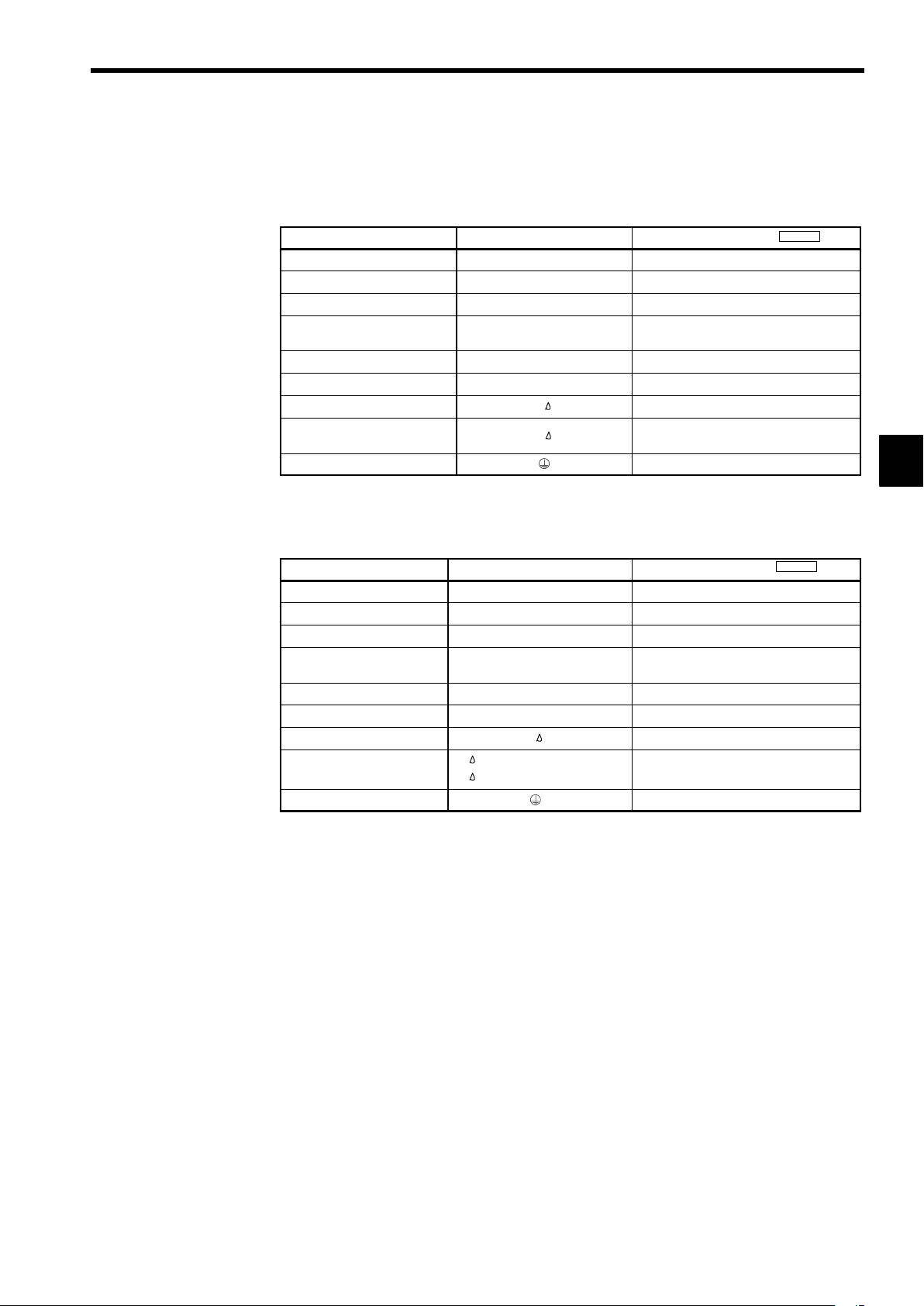
3.4.2 Main Circuit Terminal Functions
Main circuit terminal functions are summarized according to terminal symbols in Table 3.4 and Table
3.5. Wire the terminals correctly for the desired purposes.
Table 3.4 200 V Class Main Circuit Terminal Functions
Purpose Terminal Symbol
Main circuit power input
Inverter outputs
DC power input
Braking Resistor Unit connection
DC reactor connection
Braking Unit connection
Cooling fan power input
Cooling fan power input
(control power input)
Ground
Note 1.Models CIMR-G5A2030 to 2075 do not support DC power input.
2. When using this terminal as an input for DC power supply, special considerations are required. Be sure to consult our sales representative.
Table 3.5 400 V Class Main Circuit Terminal Functions
Purpose Terminal Symbol
Main circuit power input
Inverter outputs
DC power input
Braking Resistor Unit connection
DC reactor connection
Braking Unit connection
Cooling fan power input
Cooling fan power input
(control power input)
Ground
r − 200: 200 to 230 VAC input
r − 400: 380 to 460 VAC input
3.4 Wiring Main Circuit Terminals
Model: CIMR-G5A
R (L1), S (L2), T (L3) 20P4 to 2075
U (T1), V (T2), W (T3) 20P4 to 2075, D030 to D075 (all models)
¨ 1 − ©
B1, B2 20P4 to 27P5
¨ 1 − ¨ 2
¨ 3 − © (see note 2)
r,
r,
R (L1), S (L2), T (L3) 40P4 to 4300
U (T1), V (T2), W (T3) 40P4 to 4300, E055 to E160 (all models)
¨ 1 − ©
B1, B2 40P4 to 4015
¨ 1 − ¨ 2
¨ 3 − © (see note 2)
r,
20P4 to 2022, D030 to D075
20P4 to 2015
2011 to 2075, D030 to D075
2018 to 2022
2030 to 2075, D030 to D075
20P4 to 2075, D030 to D075 (all models)
Model: CIMR-G5A
40P4 to 4045, 4185 to 4300, E055 to E160
40P4 to 4015
4018 to 4300, E055 to E160
4018 to 4045
4055 to 4300, E055 to E160
40P4 to 4300, E055 to E160 (all models)
3
Note 1.Models CIMR-G5A4055 to 4160 do not support DC power input.
2. When using this terminal as an input for DC power supply, special considerations are required. Be sure to consult our sales representative.
3-9
Page 46

Wiring
3.4.3 Main Circuit Configurations
3.4.3 Main Circuit Configurations
200 V Class
J
The main circuit configurations are shown in Figure 3.4 and Figure 3.5.
3
CIMR-G5A20P4 to 21P5 (0.4 to 1.5 kW)
B2B1
U(T1)
+
Control
circuits
V(T2)
W(T3)
(DCL
option)
*1
¨1
¨2
R(L1)
S(L2)
*2
T(L3)
©
Power
supply
(RCC)
CIMR-G5A2011 to 2015 (11, 15 kW)
¨3
+
Fin cooling fan
Control
circuits
U(T1)
V(T2)
W(T3)
(DCL
option)
¨1
1
*
¨2
R(L1)
S(L2)
2
*
T(L3)
©
Power
supply
(RCC)
CIMR-G5A22P2 to 27P5 (2.2 to 7.5 kW)
B2B1
U(T1)
+
Control
circuits
V(T2)
W(T3)
(DCL
option)
*1
¨1
¨2
R(L1)
S(L2)
2
*
T(L3)
©
Power
supply
(RCC)
Fin cooling fan
CIMR-G5A2018 to 2022 (18.5, 22 kW)
¨1
¨2
1
*
R
S
3
*
T
©
r
Fin cooling fan
Power
supply
(RCC)
¨3
+
Internal
cooling fan
Control
circuits
U
V
W
CIMR-G5A2030 to 2075 (30 to 75 kW)
¨3
R
S
1
*
T
©
r
Fin cooling fan
Power
supply
(RCC)
+
Internal
cooling fan
Control
circuits
U
V
W
CIMR-G5AD030 to D075 (30 to 75 kW)
¨1
©
* 1 Prewired at the factory.
* 2 Remove the short-circuit bar from between ¨1 and ¨2 when connecting a DC
reactor to Inverters of 15 kW or less.
* 3 Prewired at the factory. When supplying power to the main circuits from the DC
power supply, remove the wiring from R-r and S- .
Fig 3.4 200 V Class Inverter Main Circuit Configurations
¨3
U
+
Power supply (RCC)
r
Fin cooling fan
Control
circuits
V
W
3-10
Page 47
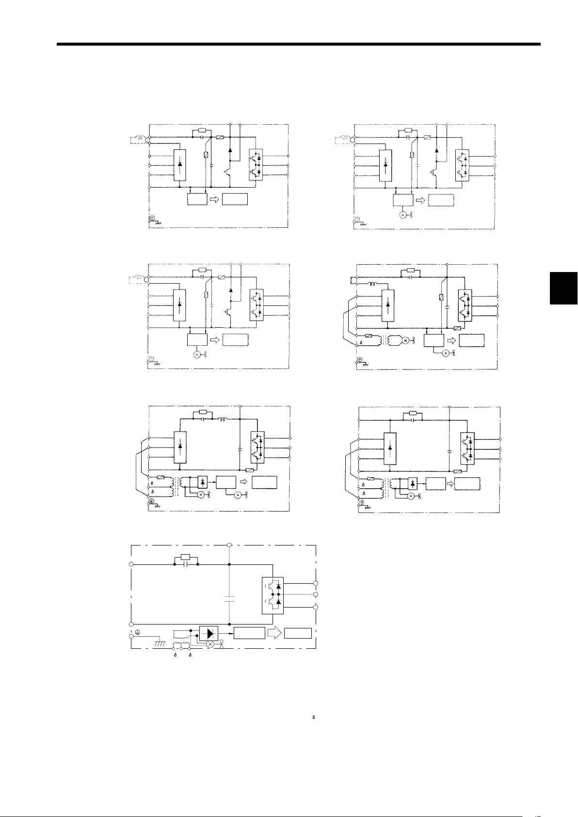
400 V Class
J
3.4 Wiring Main Circuit Terminals
CIMR-G5A40P4 to 41P5 (0.4 to 1.5 kW)
B2B1
U(T1)
+
Control
circuits
V(T2)
W(T3)
(DCL
option)
1
*
¨1
¨2
R(L1)
S(L2)
2
*
T(L3)
©
Power
supply
(RCC)
CIMR-G5A45P5 to 43P7 (5.5 to 3.7 kW)
B2B1
Control
circuits
U(T1)
V(T2)
W(T3)
+
(DCL
option)
1
*
¨1
¨2
R(L1)
S(L2)
2
*
T(L3)
©
Power
supply
(RCC)
Fin cooling fan
CIMR-G5A42P2 to 43P7 (2.2 to 3.7 kW)
B2B1
U(T1)
+
Control
circuits
V(T2)
W(T3)
(DCL
option)
1
*
¨1
¨2
R(L1)
S(L2)
2
*
T(L3)
©
Power
supply
(RCC)
Fin cooling fan
CIMR-G5A4018 to 4045 (18.5 to 45 kW)
¨1
¨2
1
*
R
S
3
*
T
©
r
Fin cooling fan
Power
supply
(RCC)
¨3
+
Control
circuits
Internal
cooling fan
U
V
W
3
CIMR-G5A4055 to 4160 (55 to 160 kW)
¨3
R
S
1
*
T
©
r
200
400
Fin cooling fan
Power
supply
(RCC)
Internal
cooling fan
+
Control
circuits
CIMR-G5AE055 to E160 (55 to 160 kW)
¨3
¨1
+
©
r
200 400
Fin cooling fan
Power supply (RCC)
U
V
W
Control
circuits
CIMR-G5A4185 to 4300 (185 to 300 kW)
Power
supply
(RCC)
¨3
+
¨1
R
S
3
*
T
©
r
200
400
U
V
W
Fin cooling fan
Control
circuits
U
V
W
* 1 Prewired at the factory.
* 2 Remove the short-circuit bar from between ¨1 and ¨2 when connecting a DC
reactor to Inverters of 15 kW or less.
* 3 Prewired at the factory. When supplying power to the main circuits from the DC
power supply, remove the wiring from R-r and S- .
Fig 3.5 400 V Class Inverter Main Circuit Configurations
3-11
Page 48

Wiring
3.4.4 Standard Connection Diagrams
3.4.4 Standard Connection Diagrams
3
CIMR-G5A20P4 to 27P5, 40P4 to 4015
DC reactor
(optional)
©¨1 ¨2B1 B2
R
S
3-phase 200 VAC
(400 VAC)
T
Be sure to remove the short-circuit bar before
connecting a DC reactor.
Braking Resistor
Unit (optional)
U
V
W
CIMR-G5A2018, 2022, 4018 to 4045
Braking Resistor
Unit (optional)
Braking Unit
(optional)
©¨1 ¨2
¨3
U
V
W
3-phase 200 VAC
(400 VAC)
R
S
T
r
*2
CIMR-G5A2011, 2015
Braking Resistor
¨3
Unit (optional)
Braking Unit
(optional)
©¨1 ¨2
U
V
W
IM
DC reactor
(optional)
IM
3-phase 200 VAC
R
S
T
Be sure to remove the short-circuit bar before
connecting a DC reactor.
CIMR-G5A2030 to 2075
Braking Resistor
Unit (optional)
Braking Unit
(optional)
R
IM
3-phase 200 VAC
S
T
r*1
©¨3
U
V
W
*2
IM
The DC reactor is built in.
CIMR-G5A4055 to 4160
R
S
3-phase 400 VAC
T
r*1
200
400 *2
¨3
Braking Resistor
Unit (optional)
Braking Unit
(optional)
©
U
V
W
IM
The DC reactor is built in.
CIMR-G5A4185 to 4300
¨1
R
S
3-phase 400 VAC
T
r*1
200
400 *2
Braking Resistor
Unit (optional)
Braking Unit
(optional)
©¨3
U
V
W
IM
The DC reactor is built in.
* 1 Input the control circuit power supply from r− for 200 V class Inverters of 30 to 75 kW (B2030 to B2075) and
from r- 400 for 400 V class Inverters of 55 to 300 kW (B4055 to B4300). (For other models, the control power
supply is supplied internally from the main circuit DC power supply.)
* 2 The r−R, ( 400)-Sterminals are short-circuited for shipping. Remove the short wiring from the 2018, 2022,
4018 to 4045 and 4185 to 4300 when supplying power to the main circuits from the DC power supply.
Fig 3.6 Main Circuit Terminal Connections
3-12
Page 49

3.4.5 Wiring the Main Circuits
J
200 V class: 3-phase,
200 to 230 VAC,
50/60 Hz
400 V class: 3-phase,
380 to 460 VAC,
50/60 Hz
3.4 Wiring Main Circuit Terminals
This section describes wiring connections for the main circuit inputs and outputs.
Wiring Main Circuit Inputs
Installing a Molded-case Circuit Breaker
Always connect the power input terminals (R, S, and T) and power supply via a molded-case circuit breaker (MCCB) suitable for the Inverter.
Choose an MCCB with a capacity of 1.5 to 2 times the Inverter’s rated current.
D
For the MCCB’s time characteristics, be sure to consider the Inverter’s overload protection (one min-
D
ute at 150% of the rated output current).
If the same MCCB is to be used for more than one Inverter, or other devices, set up a sequence so that
D
the power supply will be turned OFF by a fault output, as shown in Figure 3.7.
Power
supply
MCCB
OFF
MC
*
ON
MC
MC
SA
VS-616G5
R
S
T
19
20
3
Fault output
(NC)
* For 400 V class Inverters, connect a 400/200 V transformer.
Fig 3.7 MCCB Installation
Installing a Ground Fault Interrupter
Inverter outputs use high-speed switching, so high-frequency leakage current is generated. Therefore, at
the Inverter primary side, use a ground fault interrupter that detects only the leakage current in the frequency range that is hazardous to humans and excludes high-frequency leakage current.
For the special-purpose ground fault interrupter for Inverters, choose a ground fault interrupter with
D
a sensitivity amperage of at least 30 mA per Inverter.
When using a general ground fault interrupter, choose a ground fault interrupter with a sensitivity am-
D
perage of 200 mA or more per Inverter and with an operating time of 0.1 s or more.
Installing a Magnetic Contactor
If the power supply for the main circuit is to be shut off during a sequence, a magnetic contactor can be
used instead of a molded-case circuit breaker.
When a magnetic contactor is installed on the primary side of the main circuit to forcibly stop the Inverter,
however, the regenerative braking does not work and the Inverter will coast to a stop.
The Inverter can be started and stopped by opening and closing the magnetic contactor on the primary
D
side. Frequently opening and closing the magnetic contactor, however, may cause the Inverter to break
down.
When the Inverter is operated with the Digital Operator, automatic operation cannot be performed after
D
recovery from a power interruption.
If the Braking Resistor Unit is used, program the sequence so that the magnetic contactor is turned OFF
D
by the contact of the Unit’s thermal overload relay.
Connecting Input Power Supply to the Terminal Block
Input power supply can be connected to any terminal R, S or T on the terminal block; the phase sequence
of input power supply is irrelevant to the phase sequence.
3-13
Page 50

Wiring
3.4.5 Wiring the Main Circuits
Installing an AC Reactor or DC Reactor
If the Inverter is connected to a large-capacity power transformer (600 kW or more) or the phase advancing
capacitor is switched, an excessive peak current may flow through the input power circuit, causing the converter unit to break down.
To prevent this, install an optional AC Reactor on the input side of the Inverter or a DC reactor to the DC
reactor connection terminals.
This also improves the power factor on the power supply side.
Installing a Surge Absorber
Always use a surge absorber or diode for inductive loads near the Inverter. These inductive loads include
magnetic contactors, electromagnetic relays, solenoid valves, solenoids, and magnetic brakes.
Wiring the Power Terminals of Inverters with 18.5 to 300 kW Outputs
For 200 V class Inverters of 18.5 to 75 kW or 400 V class Inverters of 18.5 to 45 kW, connect the r
D
and
terminals to the R and S terminals respectively. (These are shorted by a short-circuit bar for ship-
ping.)
For 400 V class, 55 to 300 kW, connect the r and 400 terminals to the R and S terminals respectively.
D
(These are shorted by a short-circuit bar for shipping.)
3
Installing a Noise Filter on Power Supply Side
Install a noise filter to eliminate noise transmitted between the power line and the Inverter.
Wiring Example 1
D
Power
supply
MCCB
MCCB
Noise
filter
VS-616G5
Other
controllers
IM
Use a special-purpose noise filter for Inverters.
Fig 3.8 Correct Power supply Noise Filter Installation
Wiring Example 2
D
Power
supply
MCCB
MCCB
Generalpurpose
noise filter
VS-616G5
Other
controllers
IM
Power
supply
MCCB
MCCB
Generalpurpose
noise filter
VS-616G5
Other
controllers
IM
Do not use general-purpose noise filters. No general-purpose noise filter can effectively suppress
noise generated from the Inverter.
Fig 3.9 Incorrect Power supply Noise Filter Installation
3-14
Page 51

Wiring on the Output Side of Main Circuit
J
Connecting the Inverter and Motor
Connect output terminals U, V, and W to motor lead wires U, V, and W, respectively.
Check that the motor rotates forward with the forward run command. Switch over any two of the output
terminals to each other and reconnect if the motor rotates in reverse with the forward run command.
Never Connect a Power Supply to Output Terminals
Never connect a power supply to output terminals U, V, and W.If voltage is applied to the output terminals,
the internal circuits of the Inverter will be damaged.
Never Short or Ground Output Terminals
If the output terminals are touched with bare hands or the output wires come into contact with the Inverter
casing, an electric shock or grounding will occur. This is extremely hazardous. Do not short the output
wires.
Do Not Use a Phase Advancing Capacitor or Noise Filter
Never to connect a phase advancing capacitor or LC/RC noise filter to an output circuit. Doing so may
result in damage to the Inverter or cause other parts to burn.
3.4 Wiring Main Circuit Terminals
Do Not Use an Electromagnetic Switch or Magnetic Contactor
Do not connect an electromagnetic switch or magnetic contactor to an output circuit. If a load is connected
to the Inverter during operation, a surge current will actuate the overcurrent protective circuit in the Inverter.
Installing a Thermal Overload Relay
This Inverter has an electronic thermal protection function to protect the motor from overheating. If, however, more than one motor is operated with one Inverter or a multi-polar motor is used, always install a
thermal relay (THR) between the Inverter and the motor and set L1-01 to 0 (no motor protection).
Set the thermal overload relay to the value on the motor nameplate when operating at 50 Hz and to 1.1 times
the value on the nameplate when operating at 60 Hz. The sequence should be designed so that the contacts
of the thermal overload relay turn OFF the magnetic contactor on the main circuit inputs.
Installing a Noise Filter on Output Side
Connect a noise filter to the output side of the Inverter to reduce radio noise and inductive noise.
Power
supply
MCCB
VS-616G5
Noise
filter
Signal
line
Inductive
noise
Controller
IM
Radio noise
AM radio
Inductive Noise: Electromagnetic induction generates noise on the signal line, causing the control-
ler to malfunction.
Radio Noise: Electromagnetic waves from the Inverter and cables cause the broadcasting radio
receiver to make noise.
3
Fig 3.10 Installing a Noise Filter on the Output Side
Countermeasures Against Inductive Noise
As described previously, a noise filter can be used to prevent inductive noise from being generated on the
output side. Alternatively, cables can be routed through a grounded metal pipe to prevent inductive noise.
Keeping the metal pipe at least 30 cm away from the signal line considerably reduces inductive noise.
Power
supply
MCCB
VS-616G5
Metal pipe
IM
30 cm min.
Signal line
Controller
Fig 3.11 Countermeasures Against Inductive Noise
3-15
Page 52

Wiring
3.4.5 Wiring the Main Circuits
Countermeasures Against Radio Interference
Radio noise is generated from the Inverter as well as from the input and output lines. To reduce radio noise,
install noise filters on both input and output sides, and also install the Inverter in a totally enclosed steel
box.
The cable between the Inverter and the motor should be as short as possible.
3
Power
supply
MCCB
Noise
filter
Fig 3.12 Countermeasures Against Radio Interference
Cable Length between Inverter and Motor
If the cable between the Inverter and the motor is long, the high-frequency leakage current will increase,
causing the Inverter output current to increase as well. This may affect peripheral devices. To prevent this,
adjust the carrier frequency (set in C6-01 to C6-03) as shown in Table 3.6 . (For details, refer to the user
constant settings.)
Table 3.6 Cable Length between Inverter and Motor
Cable length 50 m max. 100 m max. More than 100 m
Carrier frequency
(Set value: C6-01)
(Set value: C6-02)
(Set value: C6-03)
Ground Wiring
J
Always use the ground terminal of the 200 V Inverter with a ground resistance of less than 100 Ω and
D
that of the 400 V Inverter with a ground resistance of less than 10 Ω.
Do not share the ground wire with other devices, such as welding machines or power tools.
D
Always use a ground wire that complies with technical standards on electrical equipment and mini-
D
mize the length of the ground wire.
Leakage current flows through the Inverter. Therefore, if the distance between the ground electrode
and the ground terminal is too long, potential on the ground terminal of the Inverter will become unstable.
When using more than one Inverter, be careful not to loop the ground wire.
D
Steel box
VS-616G5
15 kHz max. 10 kHz max. 5 kHz max.
Noise
filter
(15.0) (10.0) (5.0)
(15.0) (10.0) (5.0)
(0) (0) (0)
Metal pipe
IM
OK
OK
NO!
Fig 3.13 Ground Wiring
3-16
Page 53

Connecting the Braking Resistor (ERF)
tion)
tion)
J
Connect the braking resistor as shown in Figure 3.14.
L8-01 (Overheat protection of braking
resistor)
L3-04 (Stall prevention during decelera-
3.4 Wiring Main Circuit Terminals
1 (Enables overheat protection)
0 (Disables stall prevention function)
(Select either one of them.)
B1
VS-616G5
B2
3 (Enables stall prevention function with braking
resistor)
Braking resistor
The braking resistor connection terminals are
B1 and B2. Do not connect to any other terminals. Connecting to any terminals other than
B1 or B2 can cause the resistor to overheat,
resulting in damage to the equipment.
Fig 3.14 Connecting the Braking Resistor
Connecting the Braking Resistor Unit (LKEB) and Braking Unit (CDBR)
J
Connect the Braking Resistor Unit and Braking Unit to the Inverter as shown in the Figure 3.15.
L8-01 (Overheat protection of braking
resistor)
L3-04 (Stall prevention during decelera-
(Select either one of them.)
0 (Disables overheat protection)
0 (Disables stall prevention function)
3 (Enables stall prevention function with braking
resistor)
Set L8-01 to “1” before operating the Inverter with the braking resistor without thermal overload relay trip
contacts.
The Braking Resistor Unit cannot be used and the deceleration time cannot be shortened by the Inverter
if L3-04 is set to “1” (i.e., if stall prevention is enabled for deceleration).
To prevent the Unit from overheating, design the sequence to turn OFF the power supply for the thermal
overload relay trip contacts of the Unit as shown in Figure 3.15.
3
200 V Class Inverters with 3.7 to 7.5 kW Output and
400 V Class Inverters with 3.7 to 15 kW Output
LKEB Braking Re-
sistor Unit
B1
VS-616G5
B2
P
B
1
2
Thermal overload
relay trip contact
3-17
Page 54

Wiring
3.4.5 Wiring the Main Circuits
200 V Class Inverters with 11 kW or higher Output and
400 V Class Inverters with 18.5 or higher Output
3
LKEB Braking Re-
sistor Unit
P
B
VS-616G5
¨3
©
CDBR Brak-
ing Unit
¨
©
34
Thermal overload
relay trip contact
¨
0
©
0
Fig 3.15 Connecting the Braking Resistor Unit and Braking Unit
1
Thermal protector
trip contact
2
3-18
Page 55

3.4 Wiring Main Circuit Terminals
Connecting Braking Units in Parallel
When connecting two or more Braking Units in parallel, use the wiring and connectors shown in Figure
3.16. There are connectors for selecting whether each Braking Unit is to be a Master or Slave. Select “Mas-
ter” for the first Braking Unit only, and select “Slave” for all other Braking Units (i.e., from the second
Unit onwards).
Braking resistor overheating contacts (Thermal
¨ 3 ©
protector contacts)
12
Braking
Resistor
Unit
PB
¨
©¨0 ©0
MASTER
VS-616G5
1
2
Braking Unit #1
Level
detector
SLAVE
+15
5
6
434343
Cooling fin overheating
contacts (thermoswitch
contacts)
Fig 3.16 Connecting Braking Units in Parallel
Power Supply Sequence
MCCB
Three-phase power:
200 to 230 V, 50/60 Hz
or
380 to 460 V, 50/60 Hz
R
S
T T (L3)
* 400/200 V
Braking resistor overheating contacts (Thermal
protector contacts)
12
Braking
Resistor
Unit
PB
¨©¨0 ©0 ¨©¨0 ©0
MASTER
SLAVE
1
Braking Unit #2
P
2
Cooling fin overheating
contacts (thermoswitch
contacts)
5
1
Braking Unit #3
P
6
2
Cooling fin overheating
contacts (thermoswitch
contacts)
MC
R (L1)
S (L2)
Braking resistor overheating contacts (Thermal
protector contacts)
12
Braking
Resistor
Unit
PB
MASTER
SLAVE
5
6
3
THRX OFF ON MC
Overload relay trip contact
of Braking Resistor Unit
12
MC
20 18
* Use a transformer with 200 and 400 V outputs for the power supply of the
400 V Inverter.
Fig 3.17 Power Supply Sequence
MC
SA
THRX
SA
TRX
SA
TRX
Fault contacts
VS-616G5
3-19
Page 56

Wiring
3.5.1 Wire Sizes and Closed-loop Connectors
3.5 Wiring Control Circuit Terminals
A control signal line must not be longer than 50 m and must be separated from power lines.
The frequency reference must be input to the Inverter through twisted-pair wires.
3.5.1 Wire Sizes and Closed-loop Connectors
Terminal numbers and wire sizes are shown in Table 3.7.
Table 3.7 Terminal Numbers and Wire Sizes (Same for all Models)
Terminals
1 to 11, 13 to 33 M3.5
12 (G) M3.5 0.5 to 2
The closed-loop connectors and tightening torques for various wire sizes are shown in Table 3.8.
Terminal
Screws
Wire Thickness
Stranded wire: 0.5 to
1.25
Single wire: 0.5 to 1.25
[mm
2
]
Wire Type
S Shielded, twisted-pair wire
S Shielded,polyethylene-covered, vinyl sheath
cable
3
Table 3.8 Closed-loop Connectors for Ground Terminal
Wire Thickness
2
]
[mm
0.5 1.25 to 3.5
0.75
1.25
2 2 to 3.5
Terminal
Screws
M3.5
Crimp Size Tightening Torque (N⋅m)
1.25 to 3.5
1.25 to 3.5
0.8
3-20
Page 57

3.5 Wiring Control Circuit Terminals
i
t
(
)
Phot
H1-06.)
Analog
Master
speed
frequence
refer-
sg as
p
Running
signal
(1NO
contact)
Contact
capacity:
Open-collector
output
signals
y
pg()
FaultwhenOPEN
d201
A
t
250VAC
Analog
p
2mA
3.5.2 Control Circuit Terminal Functions
The functions of the control circuit terminals are shown in Table 3.9 . Use the appropriate terminals for
the correct purposes.
Table 3.9 Control Circuit Terminals
Type No. Signal Name Function Signal Level
1
Forward run/stop command Forward run when CLOSED; stopped when OPEN.
2
Reverse run/stop command Reverse run when CLOSED; stopped when OPEN.
3
External fault input
4
Se-
quence
npu
signals
input
signals
Se-
quence
output
output
signals
* When driving an L load, such as a relay coil, always insert a flywheel diode as shown in Figure 3.18.
Fault reset Reset when CLOSED
Multi-step speed reference 1
5
(Master/auxiliary switch)
6
Multi-step speed reference 2
7
Jog frequency reference Jog run when CLOSED.
8
External baseblock
11
Sequence input common
15
15 V power output 15 V power supply for analog references
33
−15 V power output −15 V power supply for analog references
13
Master speed frequence reference
14
16
Multi-function analog input
17
Control common
Shield wire, optional ground
12
line connection point
9
Running signal (1NO contact)
10
25
Zero speed detection
26
Speed agree detection
27
Open-collector output common
18
19
Fault output signal (SPDT)
20
21
Frequency output 0 to 10 V/100% frequency
22
Common
23
Current monitor 5 V/Inverter’s rated current
Fault when CLOSED; normal
when OPEN.
Auxiliary frequency reference
when CLOSED.
Multi-step setting 2 when
CLOSED.
Inverter output stopped when
CLOSED.
−10 to 10 V/−100% to 100%
0 to 10 V/100%
4 to 20 mA/100%, −10 to +10 V/−100% to 100%
0 to +10 V/100%
−10 to 10 V/−100% to 100%
0 to 10 V/100%
Operating when CLOSED.
Zero level (b2-01) or below
when CLOSED
Within ±2 Hz of set frequency
when CLOSED.
Fault when CLOSED across 18 and 20
across19an
Multi-function contact inputs
Command signals can be
selected by setting H1-01 to
H1-06.
Auxiliary analog input
(H3-05)
Multi-function outputs
Multi-function analog monitor 1
(H4-01, H4-02)
Multi-function analog monitor 2
(H4-04,H4-05)
24 VDC, 8 mA
ocouplerisolation
15 V
(Max. current: 20 mA)
−15 V
(Max. current: 20 mA)
−10 to 10 V (20 kΩ),
0to10V(20kΩ)
4 to 20 mA (250 Ω)
−10 to 10 V (20 kΩ),
0to10V(20kΩ)
Dry contacts
Contact ca
1 A max. at 250 VAC
1 A max. at 30 VDC
Open-collector output
50 mA max. at 48 V*
Dry contacts
Contact capacity:
1 A max. at 30 VDC
0to±10 V max. ±5%
acity:
max. a
max.
3
External power:
48 V max.
Coil
50 mA max.
Fig 3.18 Flywheel Diode Connection
3-21
Flywheel diode
The rating of the flywheel diode
must be at least as high as the circuit voltage.
Page 58

Wiring
3.5.3 Control Circuit Terminal Connections (All Models)
3
123 4567 8
3.5.3 Control Circuit Terminal Connections (All Models)
Forward run/stop
Reverse run/stop
Multi-function contact input 1
Multi-function contact input 2
Multi-function contact input 3
Multi-function contact input 4
Multi-function contact input 5
Multi-function contact input 6
Sequence input common
Frequency reference
power supply +15 V
Frequency reference
power supply −15 V
Frequency reference
input (voltage)
Frequency reference
input (current)
Multi-function analog
input
Frequency reference
input common
13 14 15 16 17
25 26 27 33 18 19 2011 12(G)
21 22 23 9 10
Fig 3.19 Control Circuit Terminal Arrangement
Connections to VS-616G5 control circuit terminals are shown in Figure 3.20.
18
1
2
3 (External fault)
4 (Fault reset)
5 (Multi-step speed
reference 1)
6 (Multi-step speed reference 2)
7 (Jog frequency reference)
8 (External baseblock)
11
12 (G)
15
33
13
14
16 (Auxiliary frequency reference)
17
Fault output (NO)
19
Fault output (NC)
20
Fault output common
9
Multi-function contact output
10
Multi-function contact
output common
25
Multi-function output 1
(Zero speed signal)
26
Multi-function output 2
(Speed agree signal)
27
Multi-function output common
21
23
22
(Running signal)
Multi-function analog
output 1
Voltmeter
FM
(Output frequency)
Multi-function analog
output 2
AM
Voltmeter (Output current)
Multi-function analog
output common
Factory presets are shown in parentheses.
When driving an L load, such as a relay coil, always insert a flywheel diode as shown in Figure 3.18.
Fig 3.20 Control Circuit Terminal Connections
3-22
Page 59

3.5.4 Control Circuit Wiring Precautions
D
Separate control circuit wiring (terminals 1 to 33) from main circuit wiring (terminals R, S, T, B1, B2,
U, V, W, ©, ¨1, ¨2, and ¨3) and other high-power lines.
Separate wiring for control circuit terminals 9, 10, 18, 19, and 20 (contact outputs) from wiring for
D
terminals 1 to 8, 21, 22, 23, 25, 26, 27, 33 and 11 to 17.
Use shielded twisted-pair cables for control circuits to prevent operating faults. Process cable ends as
D
shown in Figure 3.21.
Connect the shield wire to terminal 12(G).
D
Insulate the shield with tape to prevent contact with other signal lines and equipment.
D
Shield sheath
Connect to shield sheath
terminal at VS-616G5
(terminal 12)
Fig 3.21 Processing the Ends of Twisted-pair Cables
Insulate with tape
3.6 Wiring Check
Armor
Do not connect here.
3
3.6 Wiring Check
Check all wiring after wiring has been completed. Do not perform a buzzer check on control circuits.
Is all wiring correct?
D
Have any wire clippings, screws, or other foreign material been left?
D
Are all screws tight?
D
Are any wire ends contacting other terminals?
D
3-23
Page 60

Wiring
3.7.1 Installing a PG Speed Control Card
3.7 Installing and Wiring PG Speed Control Cards
PG Speed Control Cards are used for executing speed control using a pulse generator (PG). There are four types
of PG speed control, as shown below. Select the type that fits the application and control method.
3
PG-A2
PG-B2
PG-D2
PG-X2
A-phase (single) pulse input for open collector output or complementary outputs, for V/f control
A/B-phase pulse input for open collector output or complementary outputs, for vector control
A-phase (single) pulse input for line driver input, for V/f control
A/B/Z-phase pulse input for line driver input, for vector control
3.7.1 Installing a PG Speed Control Card
Use the following procedure to install a PG Speed Control Card.
1. Turn off the main-circuit power supply.
2. Leave it off for at least one minute before removing the front cover of the Inverter (or at least three
minutes for Inverters of 30 kW or more). Check to be sure that the CHARGE indicator is OFF.
3. Insert the spacer (which is provided) into the spacer hole in the Inverter’s mounting base.
For Inverters of 3.7 kW or lower, there are two adjacent holes. Insert the spacer into the 7CN hole. The
spacer cannot be easily removed if inserted into the wrong hole. Be very careful to insert the spacer
into the correct hole, and in the proper direction.
4. Referring to the enlarged illustration in the following diagram, align the PG Speed Control Card with
the catch position as shown by (a) and (b) and fit it precisely to the Option-A connector. Insert at (a)
first.
5. Pass the spacer through the spacer hole at the Card. (Refer to A in the illustration.) Check to be sure
that it is precisely aligned with the 4CN position, and snap it into the proper position. Be sure to press
it in firmly until you hear it snap into place.
PG Speed Control Card
4CN
Option-A
Connector
2CN
Option-C
Connector
3CN
Option-D
Connector
Spacer mounting hole
Option A
Top
7CN
Option C
Control
board
Option D
Option A mounting spacer
(Accessory: SRNT41028-9)
PG Speed
Control
Card
Inverter mounting base
Inverter
mounting base
Control board
Mounting
base side
Option A side
Spacer mounting
hole
Spacer
Connection
terminals
Ground terminal 12
Bottom
[Front]
Fig 3.22 Installing a PG Speed Control Card
3-24
(b)
(a)
Enlargement
Spacer mounting
[Side]
Page 61

3.7.2 PG Speed Control Card Terminal Blocks
+12
V/open
collector
switching
ter-
Pulse
input
terminal
pp y
p
g
)
Line
driver
input
(RS-422
level
input)
)
The terminal specifications for each PG Speed Control Card are given in the following tables.
PG-A2 (For V/f with PG Feedback Mode Only)
J
Table 3.10 PG-A2 Terminal Specifications
Terminal No. Contents Specifications
1
Power supply for pulse generator
2
3
+12 V/open collector switchingterminal
4
TA1
TA2 (E)
PG-B2 (For Flux Vector Control Mode Only)
J
5
Pulse input terminal
6
7
Pulse motor output terminal
8
Shield connection terminal
3.7 Installing and Wiring PG Speed Control Cards
12 VDC (±5%), 200 mA max.
0 VDC (GND for power supply)
Terminal for switching between12 V voltage input
and open collector input. For open collector input,
short across 3 and 4.
H: +4 to 12 V; L: +1 V max. (Maximum response
frequency: 30 kHz)
Pulse input common
12 VDC (+10%), 20 mA max.
Pulse monitor output common
3
Table 3.11 PG-B2 Terminal Specifications
Terminal No. Contents Specifications
TA1
TA2
TA3 (E)
1
Power supply for pulse generator
2
3
A-phase pulse input terminal
4
5
B-phase pulse input terminal
6
1
A-phase monitor output terminal
2
3
B-phase monitor output terminal
4
Shield connection terminal
12 VDC (±5%), 200 mA max.
0 VDC (GND for power supply)
H: +8 to 12 V
L: +1 V max.
(Maximum response frequency: 30 kHz)
Pulse input common
H: +8 to 12 V
L: +1 V max.
(Maximum response frequency: 30 kHz)
Pulse input common
Open collector output, 24 VDC, 30 mA max.
A-phase monitor output common
Open collector output, 24 VDC, 30 mA max.
B-phase monitor output common
J PG-D2 (For V/f with PG Feedback Mode Only)
Table 3.12 PG-D2 Terminal Specifications
Terminal No. Contents Specifications
TA1
TA2 (E)
1
2
Power supply for pulse generator
3
4
Pulse input + terminal
5
Pulse input − terminal
6
Common terminal
7
Pulse monitor output + terminal
8
Pulse monitor output − terminal
Shield connection terminal
12 VDC (±5%), 200 mA max. (see note)
0 VDC (GND for power supply)
5 VDC (±5%), 200 mA max. (see note)
Line driver input(RS-422 level input
Maximum response frequency: 300 kHz
Line driver output(RS-422 level output
Note 5 VDC and 12 VDC cannot be used at the same time.
3-25
Page 62

pp y
p
g
)
Line
driver
input
(RS-422
level
input)
)
3
Wiring
3.7.2 PG Speed Control Card T erminal Blocks
PG-X2 (For Flux Vector Control Mode Only)
J
Table 3.13 PG-X2 Terminal Specifications
Terminal No. Contents Specifications
TA1
TA2
TA3 (E)
1
2
Power supply for pulse generator
3
4
A-phase + input terminal
5
A-phase − input terminal
6
B-phase + input terminal
7
B-phase − input terminal
8
Z-phase + input terminal
9
Z-phase − input terminal
10
Common terminal 0 VDC (GND for power supply)
1
A-phase + output terminal
2
A-phase − output terminal
3
B-phase + output terminal
4
B-phase − output terminal
5
Z-phase + output terminal
6
Z-phase − output terminal
7
Control circuit common Control circuit GND
Shield connection terminal
12 VDC (±5%), 200 mA max. (see note)
0 VDC (GND for power supply)
5 VDC (±5%), 200 mA max. (see note)
Line driver input(RS-422 level input
Maximum response frequency: 300 kHz
Line driver output(RS-422 level output
Note 5 VDC and 12 VDC cannot be used at the same time.
3-26
Page 63

3.7.3 Wiring a PG Speed Control Card
Three-phase, 200 VAC
(400 VAC)
Wiring examples are provided in the following illustrations for the PG Speed Control Cards.
PG-A2 (For V/f with PG Feedback Mode Only)
J
12 V Voltage Input
VS-616G5
R
S
T
4CN
U
V
W
12
IM
PG-A2
1
TA1
2
3
4
5
6
7
8
4CN
E
TA2 (E)
3.7 Installing and Wiring PG Speed Control Cards
PG
+12 V power supply
0 V power supply
12 V voltage output (A/B phase)
Pulse 0 V
Pulse monitor output
3
Three-phase, 200 VAC
(400 VAC)
Fig 3.23 Wiring a 12 V Voltage Input
Open Collector Input
VS-616G5
R
S
T
4CN
U
V
W
12
IM
PG-A2
4CN
E
TA2 (E)
D Shielded twisted-pair wires must be used for signal lines.
D Do not use the pulse generator’s power supply for anything other than the
pulse generator (encoder). Using it for another purpose can cause malfunctions
due to noise.
D The length of the pulse generator’s wiring must not be more than 100 meters.
Fig 3.24 Wiring an Open-collector Input
TA1
+12 V power supply
1
0 V power supply
2
3
4
Open collector output (A/B phase)
5
Pulse 0 V
6
7
Pulse monitor output
8
PG
3-27
Page 64

Wiring
3.7.3 Wiring a PG Speed Control Card
3
PG power
supply +12 V
Short for
open-collector input
Pulse
input
TA1
I/O Circuit Configuration
1
2
1k
3
4
5
6
3k
2k
+12 V
0V
2k
+12 V
+12 V
0V
3.9 k
0V
0V
Pulse input
+12 V
1k
7
Pulse
monitor
output
8
TA1
Fig 3.25 I/O Circuit Configuration of the PG-A2
3-28
Page 65

PG-B2 (For Flux Vector Control Mode Only)
J
3.7 Installing and Wiring PG Speed Control Cards
Three-phase 200 VAC
(400 VAC)
VS-616G5
R
S
T
4CN
U
V
W
12
IM
PG-B2
TA1
4CN
TA2
E
TA3 (E)
Power supply +12 V
1
Power supply 0 V
2
A-phase pulse output (+)
3
A-phase pulse output (−)
4
B-phase pulse output (+)
5
B-phase pulse output (−)
6
1
A-phase pulse monitor output
2
3
B-phase pulse monitor output
4
D Shielded twisted-pair wires must be used for signal lines.
D Do not use the pulse generator’s power supply for anything other than the
pulse generator (encoder). Using it for another purpose can cause malfunctions
due to noise.
D The length of the pulse generator’s wiring must not be more than 100 meters.
D The direction of rotation of the PC can be set in user constant F1-05. The
factory preset if for forward rotation, A-phase advancement.
PG
3
PG power
supply +12 V
A-phase
pulse input
B-phase
pulse input
Fig 3.26 PG-B2 Wiring
I/O Circuit Configuration
TA1
1
+12 V
2
150
3
4
150 180
150
5
6
150
0V
180
470
180
470
180
Division rate circuit
A-phase
pulses
B-phase
pulses
D When connecting to a voltage-output-type PG (encoder), select a PG
that has an output impedance with a current of at least 12 mA to the
input circuit photocoupler (diode).
D The pulse monitor dividing ratio can be changed using constant
F1-06.
D The pulse monitor emitter is connected to common inside the PG-B2.
The emitter common must be used for external circuits.
Fig 3.27 I/O Circuit Configuration of the PG-B2
TA2
1
A-phase pulse monitor
2
output
3
B-phase pulse monitor
4
output
A-phase
pulses
B-phase
pulses
3-29
Page 66

Wiring
3.7.3 Wiring a PG Speed Control Card
PG-D2 (For V/f with PG Feedback Mode Only)
J
3
Three-phase 200 VAC
(400 VAC)
Three-phase 200 VAC
(400 VAC)
VS-616G5
R
S
T
4CN
U
V
W
12
IM
PG-D2
4CN
TA1
E
TA2 (E)
D Shielded twisted-pair wires must be used for signal lines.
D Do not use the pulse generator’s power supply for anything other than the pulse
generator (encoder). Using it for another purpose can cause malfunctions due
to noise.
D The length of the pulse generator’s wiring must not be more than 100 meters.
Fig 3.28 PG-D2 Wiring
PG-X2 (For Flux Vector Control Mode Only)
J
VS-616G5
R
S
T
4CN
U
V
W
4CN
IM
PG-X2
TA1
1
2
3
4
5
6
7
8
9
10
Power supply +12 V
1
Power supply 0 V
2
Power supply +5 V
3
Pulse input + (A/B phase)
4
Pulse input − (A/B phase)
5
6
7
Pulse monitor output
8
Power supply +12 V
Power supply 0 V
Power supply +5 V
A-phase pulse input (+)
A-phase pulse input (−)
B-phase pulse input (+)
B-phase pulse input (−)
PG
PG
TA2
1
2
3
4
12
E
TA3 (E)
5
6
7
A-phase pulse monitor output
B-phase pulse monitor output
Z-phase pulse monitor output
D Shielded, twisted-pair wire must be used for signal lines.
D Do not use the pulse generator’s power supply for anything other than the
pulse generator (encoder). Using it for another purpose can cause
malfunctions due to noise.
D The length of the pulse generator’s wiring must not be more than 100 meters.
D The direction of rotation of the PC can be set in user constant F1-05. The
factory preset if for forward rotation, A-phase advancement.
Fig 3.29 PG-X2 Wiring
3-30
Page 67

3.7 Installing and Wiring PG Speed Control Cards
3.7.4 Wiring PG Speed Control Card Terminal Blocks
Use no more than 100 meters of wiring for PG (encoder) signal lines, and keep them separate from power
lines.
Use shielded, twisted-pair wires for pulse inputs and pulse output monitor wires, and connect the shield
to the shield connection terminal.
J Wire Sizes (Same for All Models)
Terminal wire sizes are shown in Table 3.14 .
Table 3.14 Wire Sizes
Terminal
Pulse generator power supply
Pulse input terminal
Pulse monitor output terminal
Shield connection terminal M3.5 0.5 to 2
Solderless Terminals for Control Circuit Terminals
J
Terminal
Screws
The use of solderless terminals for the control circuit terminals is recommended because solderless terminals are easy to connect securely.
Table 3.15 Straight Solderless Terminal Sizes
Wire Thickness Model d1 d2 Manufacturer
2
0.5 mm
0.75mm
1mm
1.5 mm
2
2
2
A1 0.5-8 WH 1.00 2.60
A1 0.75-8 GY 1.20 2.80
A1 1-8 RD 1.40 3.00
A1 1.5-8 BK 1.70 3.50
Wire Thickness
(mm
Stranded wire: 0.5 to
1.25
Single wire: 0.5 to 1.25
2
)
S Shielded, twisted-pair wire
S Shielded, polyethylene-cov-
Wire Type
ered,vinylsheathcable
3
Phoenix Contact
IMPORTANT
φd1
8mm
14 mm
φd2
Fig 3.30 Straight Solderless Terminal Sizes
Do not solder wires with the control circuit terminals if wires are used instead of solderless terminals.
Wires may not contact well with the control circuit terminals or the wires may be disconnected from the control circuit terminals due to oscillation if the wires are soldered.
3-31
Page 68

3
Wiring
3.7.4 Wiring PG Speed Control Card Terminal Blocks
Closed-loop Connector Sizes and Tightening Torque
J
The closed-loop connectors and tightening torques for various wire sizes are shown in Table 3.16 .
Table 3.16 Closed-loop Connectors and Tightening Torques
Wire Thickness [mm2]
0.5 1.25 to 3.5
0.75
1.25
2 2 to 3.5
Wiring Method
J
Use the following procedure to connect wires to the terminal block.
1. Loosen the terminal screws with a thin-slot screwdriver.
2. Insert the wires from underneath the terminal block.
3. Tighten the terminal screws firmly.
Terminal
Screws
M3.5
Thin-slot screwdriver
Crimp Terminal Size Tightening Torque (N⋅m)
1.25 to 3.5
1.25 to 3.5
0.8
Blade of screwdriver
IMPORTANT
Control circuit
terminal block
Strip the end for
5.5 mm if no
solderless terminal is used.
Wires
Solderless terminal or
wire without soldering
Blade thickness: 0.6 mm max.
3.5 mm max.
Fig 3.31 Connecting Wires to Terminal Block
Wiring Precautions
1. Separate PG Speed Control Card control circuit wiring (terminals TA1 and TA2) from main circuit wiring
and other high-power lines.
2. Use twisted-pair or shielded twisted-pair cables to connect the PG to prevent operating faults. Process
cable ends as shown in Figure 3.32. The maximum cable length is 100 m.
Shield sheath
Armor
Do not connect here.
Connect to terminal
TA3 on the VS-616G5.
Insulate with tape.
Fig 3.32 Processing the Ends of Twisted-pair Cables
3. Connect the shield to the ground terminal.
4. Do not solder the wires to the control circuit terminals. The wires may not contact well with the control
circuit terminals if the wires are soldered.
5. The end of each wire connected to the control circuit terminals must be stripped for approximately
5.5 mm.
3-32
Page 69

3.7 Installing and Wiring PG Speed Control Cards
3.7.5 Selecting the Number of PG (Encoder) Pulses PG-A2/PG-B2
J
The maximum response frequency is 32,767 Hz.
Use a PG that outputs a maximum frequency of approximately 20 kHz for the rotational speed of the motor.
Motor speed at maximum frequency output (
60
r∕min
)
×
PG
rating (
p∕rev
= 20, 000 Hz
)
Some examples of PG output frequency (number of pulses) for the maximum frequency output are shown
in Table 3.17 .
Table 3.17 PG Pulse Selection Examples
Motor’s Maximum Speed (r/min) PG Rating
1800 600 18,000
1500 800 20,000
1200 1000 20,000
900 1200 18,000
Note 1.The motor speed at maximum frequency output is expressed as the sync rotation speed.
2. The PG power supply is 12 V.
3. A separate power supply is required if the PG power supply capacity is greater than
200 mA. (If momentary power loss must be handled, use a backup capacitor or other
method.)
PG power supply
Capacitor for power momentary power loss
(p/rev)
Signals
PG Output Frequency for Maximum
Frequency Output (Hz)
3
Fig 3.33 PG-B2 Connection Example
J PG-D2/PG-X2
There are 5 V and 12 V PG power supplies.
Check the PG power supply specifications before connecting.
The maximum response frequency is 300 kHz.
Use the following equation to computer the output frequency of the PG (fPG).
(Hz) =
f
PG
A separate power supply is required if the PG power supply capacity is greater than 200 mA. (If momentary power loss must be handled, use a backup capacitor or other method
Motor speed at maximum frequency output (
60
PG power
0 V 12V
Capacitor for momentary power loss
r∕min
)
×PGrating (
.)
p∕rev
)
Fig 3.34 PG-X2 Connection Example (for 12 V PG power supply)
3-33
Page 70

4
Setting User Constants
This chapter describes setting user constants using the Digital Operator.
4.1 Using the Digital Operator 4 - 2..............
4.2 Modes 4 - 5...............................
4.2.1 Inverter Modes 4 - 5..............................
4.2.2 Switching Modes 4 - 6............................
4.2.3 User Constant Access Levels 4 - 7.................
4.2.4 Operation Mode 4 - 12.............................
4.2.5 Initialize Mode 4 - 20..............................
4.2.6 Programming Mode 4 - 27..........................
4.2.7 Autotuning Mode 4 - 31............................
4.2.8 Modified Constants Mode 4 - 33.....................
4
4-1
Page 71

Setting User Constants
4.1 Using the Digital Operator
This section describes the component names and functions of the Digital Operator. The component names and
functions are shown in Figure 4.1 and Key functions are described in Table 4.1 .
4
DRIVE FWD REV REMOTE
Frequency Ref
U1−01 = 00.00 HZ
DIGITAL OPERATOR
JVOP-130
LOCAL
REMOTE
JOG
FWD
REV
RUN STOP
SEQ REF
MENU
ESC
DATA
ENTER
RESET
Operation Mode Indicators
DRIVE: Lit when in operation mode.
FWD: Lit when there is a forward run command input.
REV: Lit when there is a reverse run command input.
SEQ: Lit when the run command from the control cir-
cuit terminal is enabled.
REF: Lit when the frequency reference from control
circuit terminals 13 and 14 is enabled.
Data Display
Two-line LCD that displays data for monitoring,
user constants, and set values with 16 characters
per line.
Keys
Execute operations such as setting user constants,
monitoring, JOG, and autotuning.
Fig 4.1 Digital Operator Component Names and Functions
4-2
Page 72

Table 4.1 Key Functions
Key Name Function
LOCAL
REMOTE
LOCAL/REMOTE Key
Switches between operation (LOCAL) via the Digital Operator
and control circuit terminal (REMOTE) operation.
This Key can be enabled or disabled by setting a user constant
(o2-01).
4.1 Using the Digital Operator
MENU
ESC
JOG
FWD
REV
RESET
MENU Key Displays menus.
ESC Key
JOG Key
FWD/REV KeyJ
RESET Key
Increment Key
Decrement Key
Returns to the status before the DATA/ENTER Key was
pressed.
Enables jog operation when the VS-616G5 is being operated
from the Digital Operator.
Selects the rotation direction of the motor when the VS-616G5
is being operated from the Digital Operator.
Sets the number of digits for user constant settings.
Also acts as the reset Key when a fault has occurred.
Selects menu items, groups, functions, and user constant
names, and increments set values.
Selects menu items, groups, functions, and user constant
names, and decrements set values.
Enters menu items, functions, constants, and set values after
DATA
ENTER
DATA/ENTER Key
they are set.
Constants cannot be changed when Undervoltage (UV) is detected.
RUN
RUN Key
Starts the VS-616G5 operation when the VS-616G5 is in operation with the Digital Operator.
Stops VS-616G5 operation.
STOP
STOP Key
This Key can be enabled or disabled by setting a user constant
(o2-02) when operating from the control circuit terminal.
Note Except in diagrams, Keys are referred to using the Key names listed in the above table.
4
FWD
REV
RUN STOP
RESET
Inverter output frequency
STOP
Frequency setting
RUN
OP
ST
:
Lit:Blinking
:
Not lit
RUN
The RUN and STOP indicators light and blink to indicate operating status.
During DB (initial excitation), RUN blinks and STOP is turned ON.
Fig 4.2 RUN and STOP Indicators
STOP
4-3
Page 73

Setting User Constants
The following table shows the relationship between the indicators on the RUN and STOP Keys and the Inverter
conditions.
The indicators are lit, unlit or blinking reflecting the order of priority.
4
Priority
1
2
3
4
5
6
7
Table 4.2 Relation of Inverter to RUN and STOP Indicators
RUN
Indica-
tor
STOP
Indica-
tor
Inverter
Status
Stopped
Stopped*
Stopped
Stopped
Running
Running
Running
Conditions
Power supply is shut down.
Emergency stop
S Stop Command is sent from the Digital Operator when the control circuit
terminals were used to operate the Inverter.
S Emergency Stop Command is sent from the control circuit terminal.
Switched from LOCAL (operation using the Digital Operator) to REMOTE
(operation using the control circuit terminals) when the Run Command is
sent from the external terminal.
Switched from the Quick or Advanced Quick programming mode to the
Drive mode when the Run Command is sent from the external terminal.
The Inverter is run at a frequency below the minimum output frequency.
The Run Command is carried out when the External Baseblock Command
using the multi−function contact input terminal is issued.
Stopped
During deceleration to a stop
During DC injection braking when using the multi−function contact input
terminal.
During initial excitation of DC injection braking while the Inverter is
stopped.
During emergency deceleration
S Stop Command is sent from the Digital Operator when operating the Invert-
er using the control circuit terminals.
S Emergency Stop Command is sent from the control circuit terminal.
Run Command is issued.
During initial excitation of DC injection braking when starting the Inverter.
@
Note
*
: Lit : Blinking : Not lit
If planning to run the Inverter again, first turn OFF the Run Command and Emergency Stop Command
from the control circuit terminal and send the Run Command.
4-4
Page 74

4.2 Modes
4.2.1 Inverter Modes
4.2 Modes
This section describes the VS-616G5’s monitor modes, switching between modes, and accessing/setting user
constants.
The VS-616G5 Inverter’s user constants and monitoring functions have been organized in groups called
modes that make it easier to read and set user constants.
The VS-616G5 is equipped with 5 modes, as shown in the Table 4.3 .
Table 4.3 Modes
Mode Primary function(s)
The Inverter can be run in this mode.
Operation mode
Initialize mode
Programming mode
Autotuning mode
(See note)
Modified constants
mode
Use this mode when monitoring values such as frequency references or output
current, displaying fault information, or displaying the fault history.
Use this mode when selecting the language displayed on the Digital Operator, selecting the access level for reading/setting user constants, selecting the control
mode, or initializing the user constants.
Use this mode when reading/setting the user constants required for operation.
The program-mode functions are subdivided into the following groups:
S Application: Operation mode selection, DC control, speed search, etc.
S Tuning: Acceleration/deceleration times, S-curve characteristics, carrier
frequencies, etc.
S Reference: Settings related to frequency control
S Motor: V/f characteristics and motor constants
S Option: Settings for Optional Cards
S Terminal: Settings for sequential I/O and analog I/O
S Protection: Settings for the motor and inverter protection functions
S Operator: Selects the Digital Operator’s display and Key functions
(Usable only with in vector control mode)
Use this mode when running a motor with unknown motor constants in the vector
control mode. The motor constants are calculated and set automatically.
Use this mode to read/set user constants that have been changed from their factoryset values.
4
Note Always perform autotuning before operating in vector control mode. Refer to
tuning and 6.4.3 Autotuning for details.
5.2.5 Auto-
4-5
Page 75

Setting User Constants
4.2.2 Switching Modes
4.2.2 Switching Modes
Once the Inverter has been put into operation mode by pressing the Menu Key, the Increment and Decrement Keys can be pressed to switch to other modes. Press the DATA/ENTER Key to read/set the user
constants in each mode.
Press the ESC Key to return to the mode display from the user constant display.
Press the DATA/ENTER Key twice to write a constant and then press the ESC Key to return to the mode
display. This is the most Basic operation, so you should remember it.
4
All modes/constant
status
MENU
SOperation mode
Main Menu
G5
:
:
Operation
SInitialize mode
Main Menu
G5
:
:
Initialize
SProgramming mode
G5:Main Menu
:
Programming
SAutotuning mode
(Open loop vector control at factory
setting.)
Main Menu
G5
:
:
Autotuning
DATA
ENTER
ESC
DATA
ENTER
ESC
DATA
ENTER
ESC
DATA
ENTER
ESC
Power ON
Monitor (Frequency reference value)
Frequency Ref
U1−01 = 0.00 HZ
Operator display language selection
Select Language
English
Frequency reference input method
selection
Display contents differ depending on the
access level (A1-01)
Reference Source
Terminal
(Access level: Quick-start)
Autotuning
(Rated voltage setting)
Rated Voltage
200.0 VAC
DATA
ENTER
ESC
DATA
ENTER
ESC
DATA
ENTER
ESC
A1−00 = 1
English
Function b1
Sequence
Rated Voltage
200.0 VAC
:::
SModified constant mode
G5
Modified Consts
(Mode Display)
IMPORTANT
Displays constants changed
from factory settings
Main Menu
:
DATA
:
ENTER
None Modified
ESC
Function
(Constant Reading)
Constant Display
(Constant Setting)
Fig 4.3 Mode Transitions
When running the Inverter after using digital operator, press the MENU Key to enter the operation mode and
then press the DATA/ENTER Key from the operation mode display to bring up the monitor display. Run commands can’t be received from any other display. (Monitor display in the operation mode appears when the
power is turned ON.)
4-6
Page 76

4.2.3 User Constant Access Levels
The VS-616G5 has three access levels which divide the various user constants based on their applications,
as shown below. The access level restricts which user constants can be set or displayed.
4.2 Modes
Quick-start
Basic
Advanced
Allows reading/setting of user constants required for simple operation. (factory preset)
Allows reading/setting of Basic user constants.
Allows reading/setting of all user constants.
Set the access level in initialize mode with user constant A1-01.
J Changing the Access Level from Quick-start to Basic
The Inverter is set at the factory to start in the Quick-start access level. Use the following procedure to
change from the Quick-start level to the Basic level.
Step Key Sequence Digital Operator Display Remarks
1
MENU
2
3
DATA
ENTER
4
5
DATA
ENTER
6
7
DATA
ENTER
G5: Main Menu
Operation
G5: Main Menu
Initialize
Select Language
English
Access Level
QUICK−START
A1−01 = 2
:::
QUICK−START
A1−01 = 3
Basic
Entry Accepted
:
:
4
MENU
G5:Main Menu
Operation
G5:Main Menu
Initialize
Access Level
Basic
As shown above, Quick-start has changed to Basic.
These seven steps can be illustrated as when in Figure 4.4.
:
DATA
:
ENTER
Select Language
English
Access Level
QUICK−START
Access Level
Basic
After approx. 3 seconds, the Operator
display is as shown on the left.
DATA
ENTER
A1−01 = 2
QUICK−START
A1−01 = 3
Basic
DATA
ENTER
Entry Accepted
:::
Fig 4.4 Changing Quick-start to Basic
4-7
Page 77

Setting User Constants
4.2.3 User Constant Access Levels
Setting User Constants in Each Access Level
J
The displayed access level will change when programming mode is selected. The display will not change
for access levels in operation mode, initialize mode, autotuning mode, and modified constants mode.
This section provides the procedure to change the acceleration time to 20.0 s in each access level. The acceleration time (C1-01) is a user constant in programming mode.
If the new user constant setting is not written to the Unit by pressing the DATA/ENTER Key within one
minute after starting the procedure, the display will automatically revert to the original user constant setting. In this case, the procedure must be started again.
4
MENU
Operation mode
Initialize mode
Programming mode
DATA
ENTER
[Advanced] [Basic] [Quick-start]
Displays group level.
Application
Tuning
Reference
Displays function level.
b1 Sequence
Constant to be changed
C1 Accel/Decel
C2 S-curve Acc/Dec
Displays constant level.
b1-01 Reference Source
b1-02 Run Source
b1-03 Stopping Method
C1-01 Accel Time 1
C1-02 Decel Time 1
[Mode]
[Group]
Fig 4.5 Constant Access Levels
[Function]
[Constant]
4-8
Page 78

4.2 Modes
A
EXAMPLE
"
Setting a User Constant in the Quick-start Access Level
The user constant level will be displayed when the DATA/ENTER Key is pressed at the programming
mode display.
Use the following display to set the acceleration time to 20.0 s.
Step Key Sequence Digital Operator Display Remarks
1
MENU
2
Press twice.
3
DATA
ENTER
4
5
6
7
DATA
ENTER
8
RESET
Press twice.
9
G5:Main Menu
Operation
G5:Main Menu
Programming
Reference source
Terminals
Run Source
Terminals
Stopping Method
Ramp to Stop
Accel Time 1
C1−01 = 10.0 Sec
Accel Time 1
0010.0 Sec
Accel Time 1
0010.0 Sec
Accel Time 1
0020.0 Sec
:
:
Changed to constant setting level.
Selects the user constant so that the
leading 0 blinks. The digit that is
4
blinking can be changed.
Blinking digit moves 2 places to the
right.
Changes 1 to 2.
10
DATA
ENTER
Entry Accepted
Accel Time 1
C1−01 = 20.0 Sec
After approx. 3 seconds, the Operator
display is as shown on the left.
The acceleration time has been set to 20.0 seconds.
Step Key Sequence Digital Operator Display Remarks
11
ESC
G5:Main Menu
Programming
:
Returns to programming mode display.
4-9
Page 79

Setting User Constants
4.2.3 User Constant Access Levels
4
EXAMPLE
A
"
Setting a User Constant in the Basic Access Level
The function level will be displayed when the DATA/ENTER Key is pressed at the programming mode
display.
Use the following display to set the acceleration time to 20.0 s.
Step Key Sequence Digital Operator Display Remarks
1
2
3
4
5
6
7
8
9
MENU
Press twice.
DATA
ENTER
DATA
ENTER
DATA
ENTER
RESET
Press twice.
G5:Main Menu
Operation
G5:Main Menu
Programming
Function b1
Sequence
Function b2
DC Braking
Function C1
Accel/Decel
Accel Time 1
C1−01 = 10.0 Sec
Accel Time 1
0010.0 Sec
Accel Time 1
0010.0 Sec
Accel Time 1
0020.0 Sec
:
:
Changed to constant reading (function) level.
Changed to constant setting level,.
Selects the user constant so that the
leading 0 blinks. The blinking digit
can be changed.
Blinking digit moves 2 places to the
right and the “1” blinks.
Changes 1 to 2.
10
DATA
ENTER
Entry Accepted
Accel Time 1
C1−01 = 20.0 Sec
11
ESC
Function C1
Accel/Decel
Returns to “Function C1 Accel/Decel” display.
Writes-in the new setting.
The Operator display is as shown on
the left.
4-10
Page 80

4.2 Modes
A
EXAMPLE
"
Setting a User Constant in the Advanced Access Level
The group level will be displayed when the DATA/ENTER Key is pressed at the programming mode display.
Use the following procedure to set a constant.
Step Key Sequence Digital Operator Display Remarks
1
2
3
4
5
6
7
8
9
MENU
Press twice.
DATA
ENTER
DATA
ENTER
DATA
ENTER
DATA
ENTER
RESET
Press twice.
G5:Main Menu
Operation
G5:Main Menu
Programming
Group b
Application
Group C
Tuning
Function C1
Accel/Decel
Accel Time 1
C1−01 = 10.0 Sec
Accel Time 1
0010.0 Sec
Accel Time 1
0010.0 Sec
Accel Time 1
0020.0 Sec
:
:
Changed to constant reading (function)
level.
Selects the user constant so that the
leading 0 blinks. The blinking digit
can be changed.
4
Blinking digit moves 2 places to the
right and the “1” blinks.
Changes 1 to 2.
10
DATA
ENTER
Entry Accepted
Accel Time 1
C1−01 = 20.0 Sec
11
ESC
Function C1
Accel/Decel
Writes-in the new setting, 20.0 s.
After a few seconds, the Operator display is as shown on the left.
The constant setting in Advanced level (acceleration time change from 10.0 to 20.0 s) has been completed.
4-11
Page 81

Setting User Constants
4.2.4 Operation Mode
4.2.4 Operation Mode
Operation mode is the mode in which the Inverter can be operated.
Many user constants can’t be changed when the Inverter is operating. Refer to User Constant List for details.
The following monitor displays are possible in operation mode: The frequency reference, output frequency, output current, and output voltage, as well as fault information and the fault history.
4
IMPORTANT
All modes/constants
status
SOperation Mode
G5
When running the Inverter after using digital operator, press the MENU Key to enter the operation mode and
then press the DATA/ENTER Key from the operation mode display to bring up the monitor display.Run commands can’t be received from any other display. (Monitor display in the operation mode appears when the
power is turned ON.)
Operations in Operation Mode
J
Key operations in operation mode are shown in Figure 4.6.
Power ON (when o1-o2=1)
MENU
Main Menu
:
Operation
DATA
:
ENTER
ESC
Frequency reference setting/display
Frequency Ref
U1−01 = 0.00 HZ
Output frequency display
Output Freq
U1−02 = 0.00 Hz
Output current display
Output Current
U1−03 = 0.00 A
Power ON (when o1-02=12)
Power ON (when o1-02=3)
Output voltage display
Output Voltage
U1−06 = 0.0 VAC
Function selection U2 (fault trace)
Function U2
Fault Trace
Function selection U3 (fault history)
Function U3
Fault History
Function selection U1 (Monitor)
Function U1
Monitor
Fig 4.6 Operations in Operation Mode
This item can be changed using o1-01
Power ON (when o1-02=4)
DATA
ENTER
ESC
DATA
ENTER
ESC
DATA
ENTER
ESC
Contents of fault trace
Contents of fault history
Various monitors
U1−01 = 0.00 HZ
Current Fault
None
Last Fault
None
Frequency Ref
4-12
Page 82

Func-
U1 01
(
)
QQQ
Q
10V:
Max.
frequency
0.01
10V:
Rated
current
Shows
which
control
mode
is
10V:
Max.
frequency
0.01
Monitors
the
Inverter
s
internal
10V:
200
(400)VAC
Monitors
theDCvoltage
of
the
10V:
400
(800)
VDC
Moni
(
10V:
Max.
motor
capacity
10V:
Rated
torque
U1 10
Cantbe
output
QQQ
Q
U1 1
1
1:T
l25ON
Cantbe
output
QQQ
Q
tion
Status
tor
4.2 Modes
Conditions for Monitoring
J
Table 4.4 shows the items that can be monitored in operation mode.
The “Valid access levels” column in the table indicates whether an item can be monitored in a particular
access level and control method. The codes in this column have the following meanings.
Q
Items that can be monitored in all access levels. (Quick-start, Basic, and Advanced)
B
Items that can be monitored in the Advanced and Basic access levels.
A
Items that can be monitored only in the Advanced access level.
Items that cannot be monitored in the control mode shown.
×
The output signal levels for multi-function analog outputs shown in the table are for a gain of 100.0 and
a bias of 0.00.
Table 4.4 Constants Monitored in Operation Mode
Constant
No.
U1-01
U1-02
U1-03
U1-04
U1-05
U1-06
U1-07
-
-
U1-08
U1-09
Digital Operator
Display
Frequency reference
Frequency Ref
Output frequency
Output Freq
Output current
Output Current
Control method
Control Method
Motor speed
Motor Speed
Output voltage
Output Voltage
DC bus voltage
DC Bus Voltage
Output power
Output kWatts
Torque reference
Torque Reference
Monitors/sets the frequency reference value.
The display units can be set with
user constant o1-03.
Monitors the output frequency.
The display units can be set with
user constant o1-03.
Monitors the output current.
Shows which control mode is
set.
Monitors the motor speed.
The display unit setting can be
changed using o1-03.
Monitors the Inverter’s internal
output voltage reference value.
Monitors the DC voltage of the
Inverter’s internal main circuit.
Monitors the output power.
This is an internally detected
value.)
Monitors the internal torque reference value when vector control is used.
Function
Output Signal Levels for
Multi-function Analog Out-
puts
10 V: Max. frequency
0to±10 V possible
10 V: Max. frequency
(0 to ±10 V possible)
10 V: Rated current
(0 to +10 V output)
’
Can’t be output.
10 V: Max. frequency
(0 to ±10 V possible)
10 V: 200 (400) VAC
(0 to +10 V output)
10 V: 400 (800) VDC
(0 to +10 V output)
10 V: Max. motor capacity
(0 to ±10 V possible)
10 V: Rated torque
(0 to ±10 V possible)
Min.
Unit
0.01
0.01
0.1 A
0.01
0.1 V
1V
0.1 kW
0.1 %
Shows input ON/OFF status.
Name
Input terminal status
U1-10
Input Term Sts
U1-10 = 00000000
1: Terminal 1 ON
1: Terminal 2 ON
1: Terminal 3 ON
1: Terminal 4 ON
1: Terminal 5 ON
1: Terminal 6 ON
1: Terminal 7 ON
1: Terminal 8 ON
Can’t be output.
.
Shows output ON/OFF status.
Output terminal
status
U1-11
Output Term Sts
U1-11 = 00000000
1: Terminals 9−10 ON
ermina
1: Terminal 26 ON
Not used. (always 0)
1: Terminals 18/19−20
Can’t be output.
.
Valid Access Levels
V/f
Q Q Q Q
Hz
Q Q Q Q
Hz
Q Q Q Q
Q Q Q Q
×
Hz
Q Q Q Q
Q Q Q Q
Q Q Q Q
× ×
Q Q Q Q
Q Q Q Q
Open
V/f w/
-loop
PG
Vec-
tor
Q Q Q
Q Q
Flux
Vec-
tor
4
4-13
Page 83

Setting User Constants
U1 13
g
Cantbe
output
1
hr
QQQ
Q
U1 15
g)
(
)
0.1
%
BBB
B
U1 16
(
)
0.1
%
BBB
B
Moni
U1 17
(
)
0.1
%
BBB
B
U1 18
(q)
(
)
0.1
%
BBB
B
U1 19
()
(
)
0.1
%
×
×
B
B
U1 20
py
q
(
)
AAA
A
control
loop.
10V:
Max.
frequency
speed
control
loop.
10V:
Rated
secondary
current
within
the
speed
control
loop.
10V:
Max.
frequency
4.2.4 Operation Mode
Table 4.4 Constants Monitored in Operation Mode (Continued)
4
Func-
tion
Status
Monitor
Constant
No.
U1-12
U1-13
U1-14
U1-15
U1-16
U1-17
U1-18
U1-19
U1-20
U1-21
U1-22
U1-23
Name
Digital Operator
Display
Operation status
Int Ctl Sts 1
Cumulative operation time
Elapsed Time
Software No.
FLASH ID
Terminal 13 input
voltage level
Term 13 Level
Terminal 14 input
current level
Term 14 Level
Terminal 16 input
voltage level
Term 16 Level
Motor secondary
current (lq)
Mot SEC Current
Motor exciting current (ld)
Mot EXC Current
Output frequency
after soft-start
SFS Output
ASR input
ASR Input
ASR output
ASR Output
Speed deviation
Speed Deviation
Function
Multi-function Analog Out-
puts
Inverter operating status.
Output Signal Levels for
U1-12 = 00000000
1: Running
1: Zero-speed level
1: Reverse
1: Reset input ON
1: F.ref/F.out agree
1: Inverter ready
1: Minor fault detected
1: Major fault detected
’
Can’t be output.
Monitors the Inverter’s elapsed
operating time.
The initial value and running/
power-on time selection can be
Can’t be output. 1hr
set with user constants o2-07
and o2-08.
Manufacturer’s ID number Can’t be output.
’
’
Monitors the input voltage of
the frequency reference (voltage).
An input of 10 V corresponds to
10 V: 100% (10 V)
0to±10 V possible
100%.
Monitors the input current of the
frequency reference (current).
An input of 20 mA corresponds
20 mA: 100% (20 mA)
0 to +10 V output
to 100%.
Monitors the input voltage of
the multi-function analog input.
An input of 10 V corresponds to
10 V: 100% (10 V)
0to±10 V possible
100%.
Monitors the calculated value of
the motor’s secondary current
(Iq).
The motor’s rated secondary
10 V: Rated secondary current
0 to +10 V output
current corresponds to 100%.
Monitors the calculated value of
the motor’s excitation current
(Id).
The motor’s rated secondary
10 V: Rated secondary current
0 to +10 V output
current corresponds to 100%.
Monitors the output frequency
after a soft start.
The display shows the frequency without the correction from
10 V: Max. frequency
0to±10 V possible
compensation functions such as
slip compensation.
Monitors the input to the speed
control loop.
The max. frequency corresponds
10 V: Max. frequency
(0 to ±10 V possible)
to 100%.
Monitors the output from the
speed control loop.
The motor’s rated secondary
10 V: Rated secondary current
(0 to ±10 V possible)
current corresponds to 100%.
Monitors the speed deviation
within the speed control loop.
The max. frequency corresponds
10 V: Max. frequency
(0 to ±10 V possible)
to 100%.
Valid Access Levels
Min.
Unit
.
0.1 %
0.1 %
0.1 %
0.1 %
0.1 %
0.01
0.01 %
0.01 %
0.01 %
V/f
Q Q Q Q
Q Q Q Q
Q Q Q Q
B B B B
B B B B
B B B B
B B B B
× ×
A A A A
Hz
×
×
×
V/f w/
PG
A
A
A
Open
-loop
Vec-
tor
B B
×
×
×
Flux
Vec-
tor
A
A
A
4-14
Page 84

4.2 Modes
U1 24
(
)
0.01
%
AAA
A
U1 25
Cantbe
output
AAA
A
U1 26
(
)
0.1
V
×
×
A
A
U1 27
(
)
0.1
V
×
×
A
A
U1 28
Cantbe
output
0.1
V
AAA
A
y
U1 32
value
for
motorssecondary
cur-
10V:
100%
0.1
%
×
×
A
A
Moni
U1 33
value
for
motorsexcitation
cur-
10V:
100%
0.1
%
×
×
A
A
U1 34
Cantbe
output
AAA
A
bias
PID
feedback
volume.
bias.
Func-
Func-
tion
tion
Status
Monitor
Con-
Constant
stant
No.
No.
U1-24
U1-25
U1-26
U1-27
U1-28
U1-32
U1-33
U1-34
U1-35
Name
Digital Operator
Display
PID feedback value
PID Feedback
DI-16H2 input status
DI-16 Reference
Output voltage reference (Vq)
Voltage Ref (Vq)
Output voltage reference (Vd)
Voltage Ref (Vd)
Software No.
(CPU)
CPU ID
ACR output of q
axis
ACR (q) Output
ACR output of d
axis
ACR (d) Output
OPE fault
constant
OPE Detected
Zero servo movement pulses
Function
Function
Monitors the feedback value
when PID control is used.
The input for the max. frequency corresponds to 100%.
Monitors the reference value
from a VS-616G5-DI16H2 Digital Reference Card.
The value will be displayed in
binary or BCD depending on
user constant F3-01.
Monitors the Inverter’s internal
voltage reference value for the
’
motor’s secondary current control.
Monitors the Inverter’s internal
voltage reference value for the
’
motor’s excitation current control.
Manufacturer’s CPU software
ID number
Monitors current control output
value for motor’s secondar
cur-
rent.
Monitors current control output
value for motor’s excitation current.
Shows the first constant number
where an OPE fault is detected.
Shows the number of PG pulses
for the movement range at the
stop point for a zero servo times
4.
Output Signal Levels for
Output Signal Levels for
Multi-function Analog Out-
Multi-function Analog Out-
puts
puts
10 V: Max. frequency
0to±10 V possible
Can’t be output.
.
10 V: 200 (400) VAC
0to±10 V possible
10 V: 200 (400) VAC
0to±10 V possible
Can’t be output. 0.1 V
.
Min.
Min.
Unit
Unit
0.01 %
0.1 V
0.1 V
10 V: 100% 0.1 %
10 V: 100% 0.1 %
Can’t be output.
.
Can’t be output. 1
Valid Access Levels
Open
V/f w/
PG
-loop
Vec-
tor
V/f
A A A A
A A A A
× ×
× ×
A A
A A
A A A A
× ×
× ×
A A
A A
A A A A
× × ×
Flux
Vec-
tor
4
A
U1-36
U1-37
U1-38
PID input volume
PID Input
PID output volume
PID Output
PID command
PID Setpoint
PID command + PID command
bias − PID feedback volume.
The input for the max. frequency corresponds to 100%.
PID control output.
The input for the max. frequency corresponds to 100%.
PID command + PID command
bias.
The input for the max. frequency corresponds to 100%.
10V: Max. frequency 0.01%
10V: Max. frequency 0.01%
10V: Max. frequency 0.01%
A A A A
A A A A
A A A A
4-15
Page 85

Setting User Constants
U2 03
QQQ
Q
U2 04
QQQ
Q
U2 05
0.1
A
QQQ
Q
U2 06
×
QQQ
U2 07
0.1
V
QQQ
Q
Fault
)
U2 08
1
V
QQQ
Q
U2 09
0.1
kW
QQQ
Q
U2 10
fault
occurred.
0.1
%
×
×
Q
Q
U2 1
1
last
fault
occurred.
QQQ
Q
U2 12
last
fault
occurred.
QQQ
Q
U2 13
the
last
fault
occurred.
QQQ
Q
U2 14
time
when
the
last
fault
oc-
1
hr
QQQ
Q
4.2.4 Operation Mode
Table 4.4 Constants Monitored in Operation Mode (Continued)
4
Func-
tion
Fault
trace
(See
note.
Const
ant
No.
U2-01
U2-02
U2-03
U2-04
U2-05
U2-06
U2-07
U2-08
U2-09
U2-10
U2-11
U2-12
U2-13
U2-14
Name
Digital Operator
Display
Current fault
Current Fault
Last fault
Last Fault
Frequency reference at fault
Frequency Ref
Output frequency
at fault
Output Freq
Output current at
fault
Output Current
Motor speed at
fault
Motor Speed
Output voltage reference at fault
Output Voltage
DC bus voltage at
fault
DC Bus Voltage
Output power at
fault
Output kWatts
Torque reference
at fault
Torque Reference
Input terminal status at fault
Input Term Sts
Output terminal
status at fault
Output Term Sts
Operation status
at fault
Inverter status
Cumulative operation time at fault
Elapsed time
Function
Multi-function Analog Out-
puts
Information on the current fault
Information on the last fault
Frequency reference value when
Output Signal Levels for
“
the “last fault” occurred. Hz
”
Output frequency when the “last
”
fault” occurred. Hz
Output current when the “last
”
fault” occurred.
Motor speed when the “last
”
fault” occurred. Hz
Output voltage when the “last
”
fault” occurred.
The main circuit DC voltage
when the “last fault” occurred.
“
”
Can’t be output.
Output power when the “last
”
fault” occurred.
Min.
Units
0.01
0.01
0.1 A
0.01
0.1 V
1V
0.1 kW
Torque reference when the “last
fault” occurred.
0.1 %
(The rated torque = 100%.)
Input terminal status when the
“last fault” occurred.
(Same format as U1-10.)
Output terminal status when the
“last fault” occurred.
(Same format as U1-11.)
Inverter operating status when
the “last fault” occurred.
(Same format as U1-12.)
Elapsed operating or power-on
time when the “last fault” oc-
1hr
curred.
Valid Access Levels
Open
-loop
Vec-
tor
Flux
Vec-
V/f w/
V/f
PG
Q Q Q Q
Q Q Q Q
Q Q Q Q
Q Q Q Q
Q Q Q Q
Q Q Q
×
Q Q Q Q
Q Q Q Q
Q Q Q Q
× ×
Q Q
Q Q Q Q
Q Q Q Q
Q Q Q Q
Q Q Q Q
tor
Note When faults CPF00, 01, 02, 03, UV1 and UV2 occur, a fault trace is not performed.
4-16
Page 86

4.2 Modes
U3 02
QQQ
Q
U3 03
QQQ
Q
Information
on
the4to
last
Fault
)
U3 05
time
when
the
last
fault
oc-
1
hr
QQQ
Q
note.)
U3 06
time
when
the2to
last
fault
1
hr
QQQ
Q
U3 07
time
when
the3to
last
fault
1
hr
QQQ
Q
User
O
Func-
tion
Fault
history
(See
note.
Const
ant
No.
U3-01
U3-02
U3-03
U3-04
U3-05
U3-06
U3-07
U3-08
Name
Digital Operator
Function
Display
Most recent fault
Last Fault
Second most recent fault
Fault Message 2
Third most recent
fault
Fault Message 3
Fourth/oldest fault
Fault Message 4
Cumulative operation time at fault
Elapsed Time 1
Accumulated time
of second fault
Elapsed Time 2
Accumulated time
of third fault
Elapsed Time 3
Accumulated time
of fourth/oldest
fault
Elapsed Time 4
Information on the last fault.
Information on the 2ndto last
fault.
Information on the 3rdto last
fault.
Information on the 4thto last
fault.
Elapsed running or power-on
time when the last fault occurred.
Elapsed running or power-on
time when the 2
occurred.
Elapsed running or power-on
time when the 3
occurred.
Elapsed running or power-on
time when the 4
occurred.
Note Faults CPF00, 01, 02, 03, UV1 and UV2 are not recorded in the fault history.
J Monitoring at Startup
In operation mode, the frequency reference, output frequency, output current, and output voltage can be
monitored immediately if the factory presets are being used. One of these four values, the output voltage,
can be changed to a different monitor item. When an item other than the output voltage is to be monitored,
set that value in user constant o1-01 (Monitor selection). Refer to the example procedure given later in this
manual.
When the power is turned ON, the frequency reference will appear in the Unit’s data display if the factor
presets are being used. Any one of the four values monitored at startup (frequency reference, output frequency, output current, or the value set in user constant o1-01) can be selected to appear when the power
is turned ON.
The value that appears at startup is determined by user constant o1-02 (Monitor selection after power up).
User constants o1-01 and o1-02 can be changed in the Basic or Advanced access levels. These user
constants can be changed during operation.
nd
to last fault
rd
to last fault
th
to last fault
Output Signal Levels for
Multi-function Analog Out-
puts
Can’t be output.
Min.
Units
1hr
1hr
1hr
1hr
Valid Access Levels
Open
V/f w/
PG
-loop
Vec-
tor
V/f
Q Q Q Q
Q Q Q Q
Q Q Q Q
Q Q Q Q
Q Q Q Q
Q Q Q Q
Q Q Q Q
Q Q Q Q
Flux
Vec-
tor
4
User
Constant
Number
o1-01
J Monitor Displays
Display Name
Monitor selection
The following notation is used in this manual when describing user constants.
Change during
Operation
f
Use the last two digits from the U1 Monitor list (U1-
Setting
Range
4to38
Unit Factory Setting
jj
6
) to select a value. For example, the torque refer-
V/f
Control
B B B B
ence is U1-09, so input 9 to select the torque reference.
Change during
peration
Setting Range
Units
Factory Setting
Indicates whether or not the constant can be changed during operation.
Can be changed during operation.
f
Cannot be changed during operation.
×
The setting range for the constant.
The unit used to set the constant (“−” indicates that no unit is used).
The value preset at the factory. (There are different factory settings for each control method, i.e., if the control method is changed, the factory setting can also change.)
4-17
Valid Access Levels
PG
Open
Loop
Vector
V/f with
Flux
Vector
Page 87

Setting User Constants
V
alid
Access
User
g
4.2.4 Operation Mode
Levels
Indicates the control methods and access levels under which the constant can be accessed
and set.
Accessible/settable under all access levels (Quick-start, Basic, and Advanced).
Q
Accessible/settable under Advanced or Basic access levels.
B
Accessible/settable under Advanced access level.
A
Not accessible/settable in the specified control method.
×
4
A
EXAMPLE
User
Constant
Number
o1-02
Name
Monitor selection after power up
Change
during
Opera-
tion
f
Setting
Range
Unit
1to4 − 1
Use constant o1-02 to indicate which value will be displayed when the Inverter is started. Refer to the following table.
Monitor Display Contents at Startup
Setting Contents
1
2
3
4
"
Changing Monitor Display to Output Power at Startup in Basic Access Level
Indicates the frequency reference at startup.
Indicates the output frequency at startup.
Indicates the output current at startup.
Indicates the value set in user constant o1-01 at startup.
Change the access level to Basic if it is n o t already set there. Refer to Figure 4.4 for the procedure to
change from the Quick-start to Basic access level.
Use the following procedure to change the display from the output voltage to the output power.
Step Key Sequence Digital Operator Display Remarks
1
MENU
2
Press twice.
3
DATA
ENTER
4
Press twice.
5
DATA
ENTER
G5:Main Menu
Operation
G5:Main Menu
Programming
Function b1
Sequence
Function o1
Monitor Select
User Monitor Sel
Output Voltage
:
:
Factory
Setting
V/f
Control
V/f with
PG
B B B B
Changed to constant reading (function) level.
Changed to constant setting level.
Valid Access Levels
Open
Loop
Vector
Flux
Vector
6
7
DATA
ENTER
o1−01 = 6
Output Voltage
o1−01 = 8
:::
Output kWatts
Press twice.
8
DATA
ENTER
Entry Accepted
User Monitor Sel
Output kWatts
Writes-in the new setting.
After a few seconds, the Operator display is as shown on the left.
Output power has been set in place of output voltage.
4-18
Page 88

4.2 Modes
A
EXAMPLE
"
Changing Monitor Display to Output Current at Startup in Basic Access Level
Use the following procedure to change user constant o1-02 so that the output current is displayed at startup.
(The procedure continues from the end of the previous example.)
Step Key Sequence Digital Operator Display Remarks
1
2
3
DATA
ENTER
4
Press twice.
5
6
7
DATA
ENTER
ESC
ESC
User Monitor Sel
Output kWatts
Power-On Monitor
Frequency Ref
o1−02 = 1
:::
Frequency Ref
o1−02 = 3
Output Current
Entry Accepted
Power-On Monitor
Output Current
Function o1
Monitor Select
G5:Main Menu
Programming
:
Check the display.
Writes-in the new setting.
After a few seconds, the Operator display is as shown on the left.
4
Output current has been set in monitor selection after power ON.
4.2.5 Initialize Mode
The initialize mode is used to select the language displayed by the Unit, the access level, and the control
method; it is also used to initialize the Unit’s user constants. The structure of the initialize mode is shown
in Figure 4.7.
MENU
Operation mode
Initialize mode
Programming mode
Language
Access level
Control mode
Initialize
Password
Function Selection A2
A2-01 User Pram 1
A2-02 User Pram 2
Accessible/settable only in Advanced setting level.
Fig 4.7 Structure of Initialize Mode User Constants
4-19
A2-32 User Pram 32
Page 89

Setting User Constants
User
g
User
g
4.2.5 Initialize Mode
J
Selecting the Display Language: A1-00
Use constant A1-00 to select the language displayed by the Inverter. A value of 0 sets English and a
D
value of 1 sets Japanese.
This user constant is not returned to the factory setting when constants are initialized. It must be manu-
D
ally reset to the factory setting.
User
Constant
Number
A1-00
Name
Language selection
for Digital Operator
display
Change
during
Opera-
tion
f
Setting
Range
0 (English)
1 (Japanese)
2 (German)
3 (French)
4 (Italian)
5 (Spanish)
6 (Portuguese)
Unit
−
Factory
Setting
1
(Japanese)
Valid Access Levels
PG
Open
Loop
Vector
V/f
Control
V/f with
Q Q Q Q
Flux
Vector
4
A
EXAMPLE
"
Changing the Language to English
Use the following procedure to change the display language from Japanese to English.
Step Key Sequence Digital Operator Display Remarks
1
2
3
4
5
6
The display language has been set to English.
Setting the Access Level: A1-01
J
Use constant A1-01 to select the user constant access level. This level determines which user constants
D
can be changed and displayed.
The user constants that can be displayed and changed also depend upon the control method being used.
D
User
Constant
Number
A1-01
MENU
DATA
ENTER
DATA
ENTER
DATA
ENTER
Name
Constant access level
Change
during
Opera-
tion
f
Setting
Range
0to4 −
Changed to constant setting level.
Writes-in the new setting.
After a few seconds, the Operator display is as shown on the left.
Valid Access Levels
Factory
Unit
Setting
V/f
Control
V/f with
PG
2 (Q) Q Q Q Q
Open
Loop
Vector
Flux
Vector
4-20
Page 90

Access Level Settings
User
g
Setting Function
Operation Only
0
User Program
1
Quick-start
2
Basic
3
Advanced This setting allows all user constants to be changed or displayed.
4
Setting the Control Method: A1-02
J
Use constant A1-02 to select one of the four control methods.
D
This user constant is not returned to the factory setting when constants are initialized. It must be manu-
D
ally reset to the factory setting.
User
Constant
Number
A1-02
Name
Control method
selection
4.2 Modes
This setting allows the operation mode and initialize mode to be changed or
displayed.
Use this setting to prevent user constant settings from being changed.
This setting allows only the user-selected constants (up to 32) to be changed
or displayed.
Select the desired user constants in A2-01 through A2-32.
This setting allows the user constants required to start the Inverter (about 25)
to be changed or displayed.
This setting allows the commonly used user constants to be changed or displayed.
Change
during
Opera-
tion
Setting
Range
Unit
Factory
Setting
Valid Access Levels
V/f
V/f with
Control
PG
Open
Loop
Vector
Flux
Vector
2
×
0to3 −
(Open Loop
Vector)
Q Q Q Q
4
A
EXAMPLE
Control Method Settings
Setting Function
0
1
2
V/f control without pulse generator (normal V/f control).
V/f control with PG feedback (V/f control using a PG Speed Control Card).
Open-loop vector control
(Vector control using the Inverter internal speed information).
3
Flux vector control
(Vector control using a PG Speed Control Card).
"
Changing the Control Method to Flux Vector
Use the following procedure to change the control method to select flux vector.
Step Key Sequence Digital Operator Display Remarks
1
2
3
4
5
6
7
MENU
DATA
ENTER
Press twice.
DATA
ENTER
DATA
ENTER
G5:Main Menu
Operation
G5:Main Menu
Initialize
Select language
English
Control Method
Open Loop
A1−02 = 2
:::
Open Loop
A1−02 = 3
Flux Vector
Entry Accepted
Control Method
Flux Vector
:
:
Changed to constant setting level.
Writes-in the new setting.
After a few seconds, the Operator display is as shown on the left.
The control method has been changed to flux vector.
4-21
Page 91

Setting User Constants
User
g
4.2.5 Initialize Mode
Table 4.5 Control Method Characteristics
Characteristic V/f Control without PG V/f Control with PG Open Loop Vector Control Flux Vector Control
Basic Control
Method
Speed Detector
Optional Speed
Detectors
Speed Control
Range
Starting Torque
Speed Control
Accuracy
Torque Limit
Torque Control
Example Applica-
tions
Voltage/frequency control
(open loop)
Not required Required (pulse generator) Not required Required (pulse generator)
Not required PG-A2 or PG-D2 Not required PG-B2 or PG-X2
1:40 1:40 1:100 1:1000
150%/3 Hz 150%/3 Hz 150%/1 Hz 150 %/0 r/min
± 2to3% ± 0.03% ± 0.2% ± 0.02%
Not possible Not possible Possible Possible
Not possible Not possible Not possible Possible
S Multiple motor drives.
S Replacing existing motor
for which motor constants
are not known.
S When autotuning is not
possible.
Initializing User Constants: A1-03
J
Voltage/frequency control
with speed compensation
S Simple speed feedback
control.
S When a pulse generator is
attached to the machine
axis.
Current vector control
without PG
S Variable speed drive ap-
plications.
Current vector control with
S Simple servo drives.
S Precision speed control.
S Torque control.
PG
4
Use constant A1-03 to initialize the user constants.
D
When initialized, the user constants will return to their factory-preset values. You should normally re-
D
cord the setting of any constants that are changed from the factory presets.
User
Constant
Number
A1-03
Initialize
Name
Change
during
Opera-
tion
×
Setting
Range
0, 1110,2220
3330
,
Unit
− 0
Factory
Setting
Valid Access Levels
PG
Open
Loop
Vector
V/f
V/f with
Control
Q Q Q Q
Settings to Initialize User Constants
Setting Function
0
1110
2220
3330
Returns to the Initialize Display without initializing any user constants.
Initializes the user constants to the user settings.
2-wire sequential initialization (Initializes the user constants to the factory settings.)
3-wire sequential initialization
Initializing to User Settings
This function initializes the user constants to values that have been recorded as user settings.
Torecord the user settings, change the user constants to the desired values and then set user constant o2-03
(User constant initial value) to 1. Once user settings are recorded, the o2-03 value will be automatically
reset to 0. (The 1110 function will be disabled when user constant o2-03 is set to 0.)
Example of Wiring for 2-wire Sequential Operation
D
1
Forward Run/Stop
Flux
Vector
2
Reverse Run/Stop
11
Sequential input common
Fig 4.8 Example of Wiring for 2-wire Sequential Operation
Example of Wiring for 3-wire Sequential Operation
D
The default settings of the multi-function inputs are different from the default settings of the 2-wire
sequence.
4-22
Page 92

4.2 Modes
When setting a 3-wire sequence, the operation can be started and stopped with an automatically resetting pushbutton switch.
Stop switch (NC) Run switch (NO)
1
Run command
(Operates when the run switch is closed.)
2
Stop command
(Stops when the stop switch is open.)
5
Forward/Reverse run command
(Multi-function input 3)
11
Sequential input common
Fig 4.9 Example of Wiring for 3-wire Sequential Operation
A
EXAMPLE
"
Initializing for 2-wire Sequential Operation
Use the following procedure to initialize user constants to the factory settings.
Step Key Sequence Digital Operator Display Remarks
1
MENU
2
3
DATA
ENTER
4
Press 3 times.
5
DATA
ENTER
6
7
DATA
ENTER
The initialization has been completed for a 2-wire sequence.
G5:Main Menu
Operation
G5:Main Menu
Initialize
Select Language
English
Init Parameters
No Initialize
A1−03 = 0
:::
No Initialize
A1−03 = 2220
2-wire Initial
Entry Accepted
Init Parameters
No Initialize
:
:
4
Writes-in the new setting.
After a few seconds, the Operator display is as shown on the left.
4-23
Page 93

Setting User Constants
User
g
4.2.5 Initialize Mode
J
Passwords: A1-04, A1-05
Use constants A1-04 and A1-05 to write-protect the initialize-mode user constants.
D
User constants A1-01 through A1-03 and A2-01 through A2-32 can be displayed but not changed if
D
the contents of A1-04 and A1-05 are not the same.
To write-protect the initialize-mode user constants, set the password in A1-05 after inputting the de-
D
sired values in A1-01 through A1-03 and A2-01 through A2-32. User constant A1-05 can be displayed
by displaying A1-04 and pressing the Menu Key while pressing the Reset Key. (A1-05 can’t be displayed with the usual Key sequences.)
It will be possible to change the initialize-mode user constants again when the same password is writ-
D
ten to A1-04 and A1-05.
User
Constant
Number
A1-04
A1-05
Name
Password 1
Password 2
Change
during
Opera-
tion
×
×
Setting
Range
Unit
Factory
Setting
0 to 9999 − 0
0 to 9999 − 0
Valid Access Levels
PG
Open
Loop
Vector
V/f
Control
V/f with
Q Q Q Q
Q Q Q Q
Flux
Vector
4
A
EXAMPLE
"
Setting the Password to 1000
Use the following procedure to set the password to 1000.
Step Key Sequence Digital Operator Display Remarks
1
2
3
4
5
6
7
8
9
The password has been set to 1000.
To enable changing user constants, set the same password in A1-05 = 0.
MENU
DATA
ENTER
Press 4 times.
RESET
Hold RESET.
MENU
And press MENU.
DATA
ENTER
DATA
ENTER
ESC
G5:Main Menu
Operation
G5:Main Menu
Initialize
Select Language
English
Enter Password
A1−04 = 0
Select Password
A1−05 = 0
Select Password
0000
Select Password
1000
Entry Accepted
Select Password
A1−05 = 1000
Enter Password
A1−04 = 0
:
:
The first digit will blink. The blinking
digit can be changed.
The value of the digit will increment
each time the Increment Key is
pressed and then stop at 9. Press the
Decrement Key to decrease the value.
Writes-in the new setting.
After a few seconds, the Operator display is as shown on the left.
J Setting User Constants: A2-01 to A2-32
User constants A2-01 through A2-32 specify the constants that can be displayed and changed when
D
the access level (A1-01) is set to 1 (user programs).
User constants A2-01 through A2-32 can be changed only in the Advanced access level and cannot
D
be changed during operation.
The following restrictions apply to setting/displaying user constants when the access level is set to the
D
user program access level.
Operation
Initialize
The Quick-start level user constants can be displayed.
The Quick-start level user constants can be displayed or set.
4-24
Page 94

4.2 Modes
A
EXAMPLE
Programming
Only the user constants specified in A2-01 through A2-32 can be displayed or
set.
Autotuning
Modified constants
"
Setting C1-08 (Deceleration Time 4) in A2-01 to Define it as a User Constant
The user constants cannot be displayed.
The user constants cannot be displayed.
Step Key Sequence Digital Operator Display Remarks
1
MENU
2
G5:Main Menu
Operation
G5:Main Menu
:
:
Initialize
3
4
DATA
ENTER
Select Language
English
Function A2
User Constants
5
6
7
DATA
ENTER
DATA
ENTER
User Param 1
A2−01 = −−−−−
User Param 1
−−−−−−−
User Param 1
C1−01
Press twice.
8
RESET
User Param 1
C1−01
Press twice.
9
User Param 1
C1−08
Press 7 times.
10
DATA
ENTER
Entry Accepted
The first digit blinks.
4
Writes-in set value 0000.
Writes-in the new setting.
11
12
13
14
15
ESC
Press twice.
DATA
ENTER
Press twice.
DATA
ENTER
User Param 1
A2−01 = C1−08
Function A2
User Constants
Access Level
Advanced
A1−01 = 4
:::
Advanced
A1−01 = 1
User Program
Entry Accepted
A1−01 = 4
:::
Advanced
After a few seconds, the Operator display is as shown on the left.
The user program access level can be
set only after one or more constants
are set as user constants in A2-01 to
A2-32. If no constants are set, the
user program access level will not be
displayed for A1-01.
Writes-in the new setting.
If the DATA/ENTER Key is not
pressed within one minute, the Operator display will return as shown on
the left. In this case, repeat from step
14.
4-25
Page 95

Setting User Constants
4.2.6 Programming Mode
Step RemarksDigital Operator DisplayKey Sequence
Access Level
User Program
16
ESC
G5:Main Menu
Initialize
:
The access level has been set to the user program access level.
Figure 4.10 shows the structure of the user constants.
After a few seconds, the Operator display is as shown on the left.
4
MENU
Operation mode
Initialize mode
Programming mode
Language
Access Level
Control Method
Initialize
Password
Function Selection A2
These user constants can be changed and displayed only in
the Advanced access level.
A2-01 User Param 1
A2-02 User Param 2
A2-32 User Param 32
Fig 4.10 Structure of User Constants
4.2.6 Programming Mode
The Inverter user constants can be set in programming mode. The user constants which can be changed
and displayed depend on the access level and control method that are being used. Refer to the following
table to determine if a user constant can be changed.
The groups of constants in programming mode and their functions are shown in Table 4.6 .
4-26
Page 96

Table 4.6 Programming Mode Constant Groups
pp
Group Function Display Comments
4.2 Modes
Control Meth-
od
V/f
V/f w/PG
Open-loop Vector
Flux Vector
b Application
C Tuning
d Reference
E Motor
b1 Operating modes Sequence
b2 DC braking DC Braking
b3 Speed searching Speed Search
b4 Timer functions Delay Timers
b5 PID control PID Control
b6 Dwell functions Reference Dwell
b7 Droop control Droop Control
b8 Energy-saving control Energy Saving
b9 Zero servo Zero Servo
Acceleration/deceleration
C1
times
S-curve acceleration/de-
C2
celeration
C3 Slip compensation Motor-Slip Comp
C4 Torque compensation Torque Comp
C5 Speed control ASR Tuning
C6 Carrier frequencies Carrier Freq
Hunting prevention func-
C7
tions
C8 Factory tuning constants Factory Tuning
d1 Frequency references Preset Reference
Frequency upper/lower
d2
limits
d3 Jump frequencies Jump Frequencies
Reference frequency hold
d4
function
d5 Torque control Torque Control
E1 V/f characteristics V/f Pattern
E2 Motor constants Motor Setup
E3 Motor 2 control method Motor 2 Ctl Meth
E4 V/f Characteristics 2 V/F pattern 2
E5 Motor 2 constants Motor 2 Setup
Accel/Decel
S-Curve Acc/Dec
Hunting Prev
Reference Limits
Sequence
Settings such as the reference input
method
DC braking function settings
Speed search function settings
Timer function settings
PID control settings
Accel/decel time dwell function settings
Droop control (speed drop) settings
Terminal input energy-saving control
settings
Stop in the position loop
Acceleration/deceleration time settings
S-curve characteristics for accel/decel
times
Slip compensation function settings
Torque compensation function settings
Speed control loop user constant settings
Carrier frequency settings
Hunting prevention function for V/f
control
Adjustment for open-loop vector control
Operator frequency reference settings
Frequency upper and lower limit settings
Prohibited frequency settings
Hold for analog frequency reference
User constant settings for torque control
Sets the motor V/f characteristics.
Sets the motor constants.
Sets the control methods for motor 2.
Sets the V/f characteristics for motor 2.
Sets the motor constants for motor 2.
f f f f
f f f f
f f f f
f f f f
f f f f
f f f f
× × ×
f f
× ×
× × ×
f f f f
f f f f
f f f f
f f f
f
×
×
f f f f
f f
× ×
f
× ×
f f f f
f f f f
f f f f
f f f f
× × ×
f f f f
f f f f
f f f f
f f f f
f f f f
f
f
4
×
f
×
f
4-27
Page 97

Setting User Constants
4.2.6 Programming Mode
Group Function Display Comments
Control Meth-
od
V/f
V/f w/PG
Open-loop Vector
Flux Vector
4
F Options
H Terminal
L Protection
o Operator
PG speed control card
F1
settings
Analog Reference Card
F2
AI
F3 Digital Reference Card DI DI-08, 16 Setup
F4 Analog Monitor Card AO AO-08, 12 Setup
F5 Digital Output Card DO DO-02C
F6 Digital Output Card DO DO-08
F7 Pulse Monitor Card PO PO-36F Setup
SI-F/SI-G Transmission
F8
Card
Transmission cards other
F9
than SI-K2, SI-F/G
H1 Multi-function inputs Digital Inputs
H2 Multi-function outputs Digital Outputs
H3 Analog inputs Analog Inputs
Multi-function analog out-
H4
puts
MEMOBUS communica-
H5
tions
L1 Motor protection functions Motor Overload
Momentary power loss
L2
ride-through
L3 Stall prevention Stall Prevention
L4 Frequency detection Ref Detection
L5 Fault restart Fault Restart
L6 Overtorque detection Torque Detection
L7 Torque limits Torque Limit
L8 Hardware protection Hdwe Protection
o1 Display/Monitor settings Monitor Select
o2 Function settings Key Selections
PG Option Setup
AI-14 Setup
SI-F/G
DDS/SI-B
Analog Outputs
Serial Com Setup
PwrLoss Ridethru
User constant settings for a PG Card
User constant settings for an Analog
Reference Card
User constant settings for a Digital Reference Card
User constant settings for an Analog
Monitor Card
User constant settings for a Digital Output Card
User constant settings for a Digital Output Card
User constant settings for a Pulse Monitor Card
User constant settings for a Transmission Card
User constant settings for a Transmission Card
Function selection for multi-function
inputs
Function selection for multi-function
outputs
Function selection for analog inputs
Function selection for analog outputs
MEMOBUS communications settings
Overload protection settings and selection
Selects the power-loss processing method.
Stall prevention settings and selection
Frequency detection settings and selection
Fault restart function settings
Overtorque detection settings and selection
Torque limit settings (vector control
only)
Overheating and phase loss protection
settings
Selects the display and setting methods.
Key function selection and other user
constants
f
×
×
f f f f
f f f f
f f f f
f f f f
f f f f
f f f f
f f f f
f f f f
f f f f
f f f f
f f f f
f f f f
f f f f
f f f f
f f f f
f f f f
f f f f
f f f f
f f f f
f f
× ×
f f f f
f f f f
f f f f
f
4-28
Page 98

Figure 4.11 shows the difference in the display structure for the various access levels.
4.2 Modes
MENU
[Mode]
Operation mode
Initialize mode
Programming mode
Autotuning mode
Modified constants mode
DATA
ENTER
Advanced Level
[Group]
b Application
C Tuning
d Reference
DATA
ENTER
Basic Level
[Function]
b1 Sequence
DATA
ENTER
Quick-start Level
[Constant]
b1-01 Reference selection
b1-02 Operation method selection
b1-03 Stopping method selection
b2 DC braking b2-01 Zero speed level
b2-02 DC injection braking current
b3 Speed search
b3-01 Speed search selection at start
b3-02 Speed search operating current
C1 Accel/Decel C1-01 Acceleration time 1
C1-02 Deceleration time 1
C2 S-curve characteristic setting
C3 Motor-slip compensation
d1 Frequency refer-
C2-01 S-curve characteristic time at acceleration
start
C2-02 S-curve characteristic time at deceleration
start
C3-01 Slip compensation gain
d1-01 Frequency reference 1
ence presetting
d1-02 Frequency reference 2
4
E Motor
F Option
H Terminal
L Protection
o Operator
d2 Frequency up-
d2-01 Frequency reference upper limit
per/lower limit
d2-02 Frequency reference lower limit
d3 Jump frequency d3-01 Jump frequency 1
E1 V/f pattern setting E1-01 Input voltage setting
E1-02 Motor selection
E2 Motor setup E2-01 Motor rated current
F1 PG Speed Control
Card
F1-01 PG constant
H1 Sequence input H1-01 Digital input
H2 Sequence output H2-01 Digital output
L1 Motor protection L1-01 Motor protection selection
L2 Momentary power
L1-02 Motor protection time constant
loss ride-through
o1 Display/setting
o1-01 Monitor selection
selection
o1-02 Monitor selection after power up
o2 Function selection
o2-01 LOCAL/REMOTE Key enable/disable
o2-02 STOP Key during control circuit
terminal operation
Fig 4.11 Display Structures for Different Access Levels
4-29
Page 99
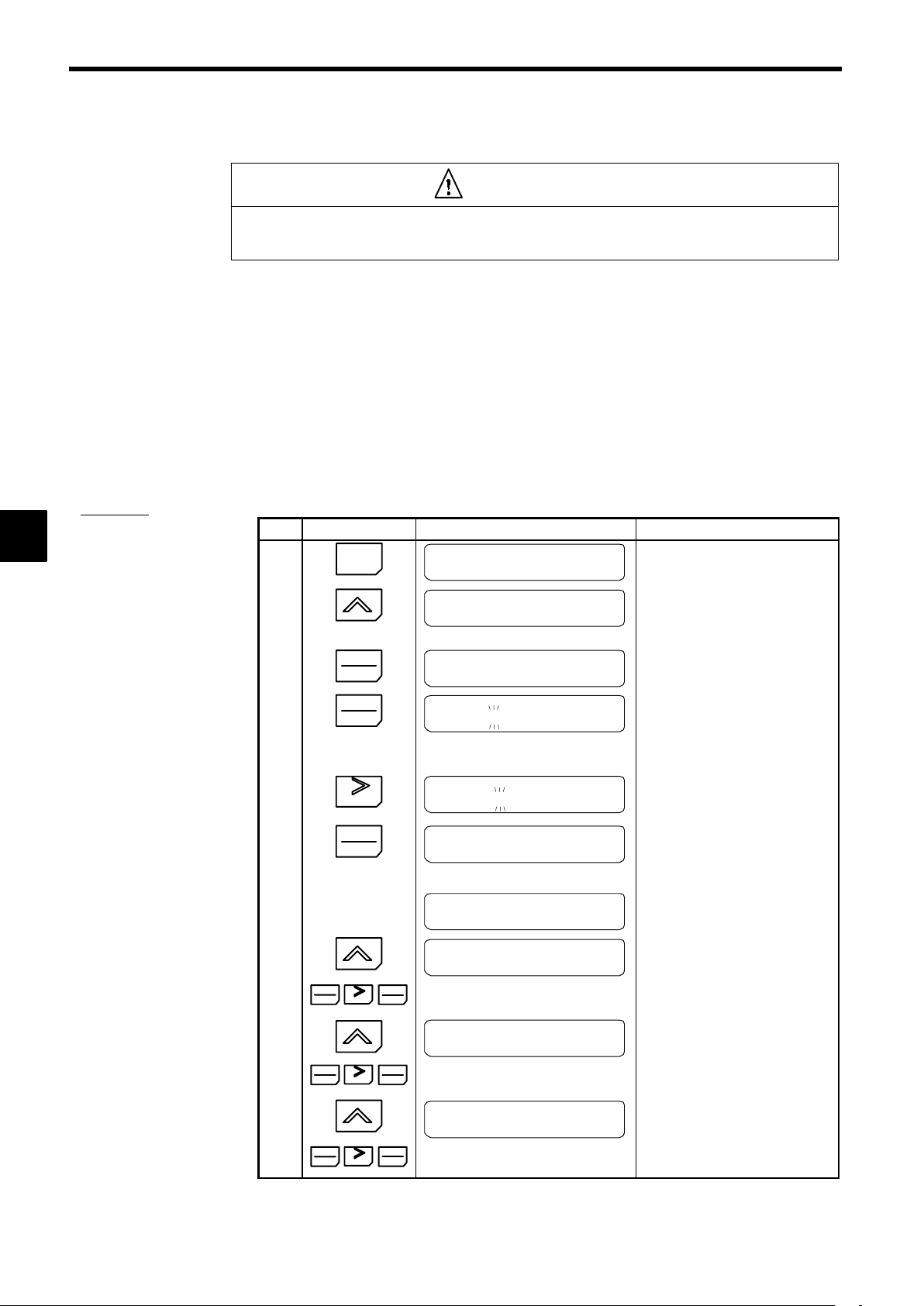
4
Setting User Constants
4.2.7 Autotuning Mode
4.2.7 Autotuning Mode
A
EXAMPLE
"
Autotuning Procedure
CAUTION
D Disconnect the load (machine, device) from the motor before autotuning.
The motor may turn, possibly resulting in injury or damage to equipment. Also, motor constants cannot be
correctly set with the motor attached to a load.
Autotuning automatically tunes and sets the required motor constants when operating in the open-loop or
flux vector control modes. Always perform autotuning before starting operation.
When the rated voltage, rated current, rated frequency, and number of poles listed on the motor nameplate
have been input and the RUN Key is pressed, the motor constants calculated from these values will be written to E1-04 through E2-09 automatically.
When the motor cannot be disconnected from the load, motor constants can be set by calculation. Contact
your Yaskawa representatives for details.
The autotuning mode won’t be displayed if V/f control has been selected. Refer to Setting the Control
Method: A1-02 under 4.2.5 Initialize Mode.
The Inverter’s autotuning function automatically determines the motor constants, while a servo system’s
autotuning function determines the size of a load, so these autotuning functions are fundamentally different.
Step Key Sequence Digital Operator Display Remarks
1
MENU
G5:Main Menu
Operation
:
10
11
12
2
G5:Main Menu
:
Autotuning
press 3 times.
3
4
DATA
ENTER
DATA
EN-
TER
Rated Voltage
200.0 VAC
Rated Voltage
200.0 VAC
∗
The leading digit blinks.
When Increment Key is pressed,
blinking value increases. When
Decrement Key is pressed, blinking
value decreases.
5
RESET
6
DATA
ENTER
Rated Voltage
200.0 VAC
Entry Accepted
The digit to be set moves to the right
and blinks. Follow the above procedures as outlined in step 4.
After selecting values for steps 4 and
5, press DATA/ENTER Key.
The Operator display is as shown on
the left. The value is written-in.
Rated Voltage
200.0 VAC
7
Rated Current
After a few seconds, the Operator display is as shown on the left.
1.90 A
DATA
8
ENTER
9
RESET
DATA
ENTER
Press the keys as in steps 4, 5, 6 of
rated voltage setting.
Rated Frequency
60.0 HZ
DATA
ENTER
RESET
DATA
ENTER
Press the keys as in steps 4, 5, 6 of
rated voltage setting.
Rated Speed
1750 RPM
DATA
ENTER
RESET
DATA
ENTER
Press the keys as in steps 4, 5, 6 of
rated voltage setting.
4-30
Page 100

4.2 Modes
Step
13
14
15
16
17
18
19
Key Sequence Digital Operator Display Remarks
Number of Poles
4
DATA
ENTER
RESET
DATA
ENTER
Press the keys as in steps 4, 5, 6 of
rated voltage setting.
Select Motor 1/2
1
DATA
ENTER
RESET
DATA
ENTER
Press the keys as in steps 4, 5, 6 of
rated voltage setting.
Leave the setting at 1 to set the value
for motor 1 (the motor contacts normally used.)
Select “2” to store the autotuning results for motor 2.
Tuning Ready?
Press RUN Key
RUN
MENU
Tune Processing
jHzjjjjA
Tune Successful
G5:Main Menu
Operation
Autotuning starts and the motor rotates for approx. one minute.
Then the motor stops automatically.
:
4
IMPORTANT
Returns to the operation mode display.
∗
The rated voltage for vector control motors may be 10% to 20% lower than that for general-purpose motors. Check the voltage on the nameplate or in the test reports.
If a fault occurs during autotuning, refer to Table 5.1 Troubleshooting Autotuning Fault s.
4-31
 Loading...