

Page 1

Varispeed-501)W11
INDUSTRIAL
USE
THYRISTOR
CONVERTER
UNITS
Before
initial
operation,
read
these
instructions
thoroughly,
and
retain
for
future
reference
.
Page 2

When
properly
installed,
operated
and
maintained,
this
unit
will
providealifetimeofoptimum
operation.It
is
mandatory
that
the
person
who
operates, inspects,
and
maintains
this
equipment
thoroughly
reads
and
understands
this
manual
andhasinhis possession
at
all
time
.
IMPORTANT
.
Make
no
withstand
voltage
testonthe
VS-505WII
because
it
incorporates
semi-conductor
electronic
circuits
.
.Ifinsulation resistance
tests
are
neccessary,
make
them
onlyinaccordance
with the
instructions
given
in
this
manual
.
682-215
Type
CDMR-W11
Type
CDMR-WIL
(Type
S)
(Type
L)
460
V,
105
A
460
V,
420
A
CONTENTS
682-234
.
Do
not
tamper
with
potentiometersofthe
power
units
since
they
were
preset
at the
factory
before
shipment
.
Varispeed-505W11
(VS-505WII)isa
thyristor
converter
unit
for
varispeed
reversible
operation
of
industrial
DC
motors
.
For
correct
operationofVS-505WII,
users
must
thoroughly read these
instructions
.
This
manualisalso
necessary
for
maintenance
and
troubleshooting,
and
threfore
should
be kept
filed
for
ready
reference
.
For
detailsonDC
motors,
referto"Instructions
for
IndustrialDCMotors"
(TOE-C435-3B)
.
Type
CDMR-W11
(Type
M)
230
V,
260
A
682-227
RECEIVING........
. . . .
3
Interconnections...........4
MAINTENANCE
. . . . . . . .
10
STORAGE............ . .
3
Cautions
when
Wiring
. . . . . .
4
Periodic
Inspection
. . . . . .
.
10
LOCATION
. . ...........
3
TEST
RUN..............
5
Parts
Replacement
. ......10
INSTALLATION.........3
Check
before
Test
CautionsinReplacing
WIRING
. . . . ............3
Run
.
. . . . . ... . . . . . ..... .
5
Control
Board
. . . . . . . . ...
14
Component
Arrangement
No-Load
Operation........
6
Troubleshooting
Guide
.
...
14
in
VS-505WH.... . . . . . . . .
3
Full-Load Operation
. . . . -
6
SPAREPARTS
. ..... . . . .
15
Terminal
Sizes
and
Carrying
Currents
. . ... . ...
4
Adjustment
.
. . .......
.
. . .
6
REFERENCE..........
. .
16
Page 3
RECEIVING
or
missing
.
STORAGE
If
the
equipment
is
temporarily
stored
or
ma-
chine stops
foranextended
length
of
time,
the
following
precautions
should
be
taken
.
LOCATION
Store
the
equipment
under
the
following
condi-
tions
.
"
Free
from
rainfall
and
drops
of
water
"
Clean
and dry
(a)
Control
Circuit
"
Free from
corrosive
gas
and
liquid
"
Ambient
temperature:OOC
to400
C
WIRII4G
Make
wiring
in
reference
to
the
interconnection
diagram
furnished
on your
order
and
the
follow-
ing
.
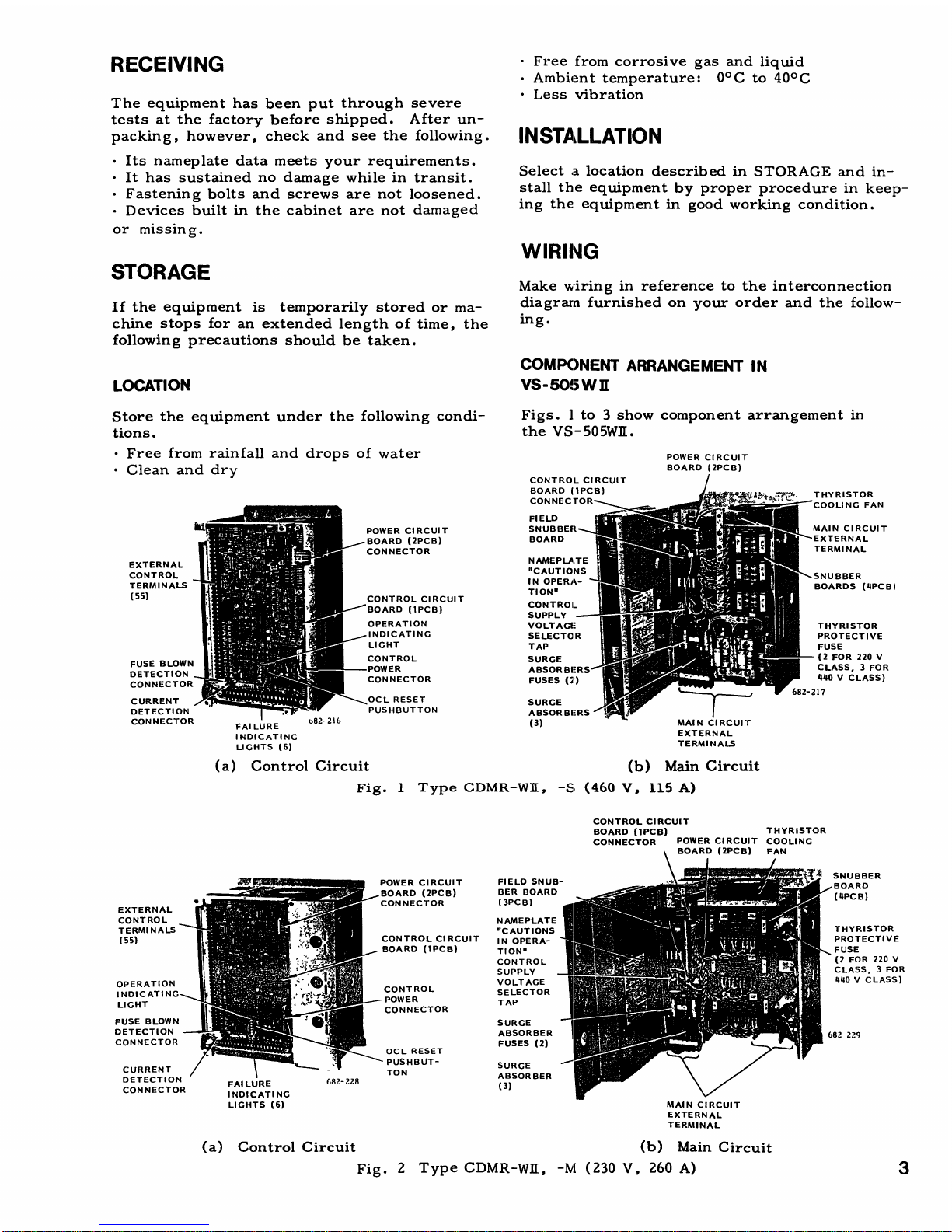
COMPONENT
ARRANGEMENT
IN
VS-505
W
II
Figs.1to3
show
component
arrangement
in
the
VS-505WII
.
NAMEPLATE
"CAUTIONS
I
NOPERA-
TION"
CONTROL
SUPPLY
VOLTAGE
SELECTOR
TAP
POWER
CIRCUIT
BOARD
(2PCB)
(a)
Control
Circuit
Fig.1
Type
CDMR-WI[,
-S,
(460V,115
A)
(b)
Main
Circuit
CONTROL
CIRCUIT
BOARD
(1PCB)
THYRISTOR
CONNECTOR
POWER
CIRCUIT
COOLING
BOARD
(2PCB)FAN
MAIN
CIRCUIT
EXTERNAL
TERMINAL
(b)
Main
Circuit
Fig
.
2
Type
CDMR-WII,
-1V[
(230
V,
260 A)
THYRISTOR
PROTECTIVE
FUSE
(2
FOR
220
V
CLASS,3FOR
440
V
CLASS)
THYRISTOR
PROTECTIVE
FUSE
(2
FOR
220
V
CLASS,3FOR
440VCLASS)
The
equipment
has
been
put
through
severe
testsatthe
factory
before
shipped.After
un-
packing,
however,
check
and
see the
following
.
"
Less
vibration
INSTALLATION
"
Its
nameplate
data
meets
your
requirements
.
"Ithas
sustained
no
damage
whileintransit
.
Select.alocation
described
in
STORAGE
and
in-
"
Fastening
bolts
and
screws are
not
loosened
.
stall
the
equipment
by proper
procedure
in
keep-
"
Devices
builtinthe cabinet are not
damaged
ing the
equipment
in
good
working
condition
.
Page 4
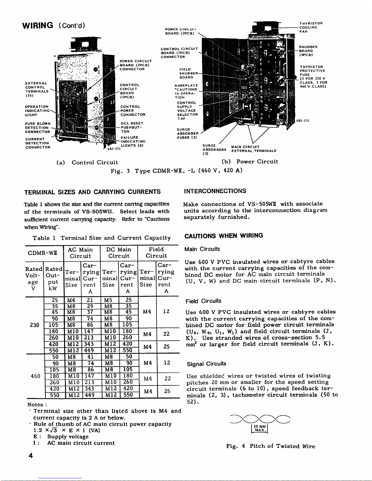
WIRING
(Cont'd)
4
TERMINAL
SIZES
AND
CARRYING
CURRENTS
Table1shows
the
size
and
the current
earring
capacities
of
the
terminals
of
VS-505WII
.
Select
leads
with
sufficient
current
carrying capacity.Referto"Cautions
when
Wiring"
.
Table
1
Terminal
Size
and
Current
Capacity
Notes
-
Terminal
size
other
than
listed
above
is
M4
and
current
capacityis2Aor
below
.
Ruleofthumb
ofACmain
circuit
power
capacity
1
.2XF
XEXI
(VA)
E
:Supply
voltage
I
:AC
main
circuit
current
SURGE
ABSORBERS
Control
Circuit
(b)
Power
Circuit
Fig.3
Type
CDMR-WII
:,
-L
(460
V,
420
A)
INTERCONNECTIONS
Make
connections
of
VS-505WII
with
associate
units
according
to
the
interconnection
diagram
separately
furnished
.
CAUTIONS
WHEN
WIRING
Main
Circuits
Use
600VPVC
insulated
wires
or
cabtyre
cables
with
the
current
carrying
capacities
of
the
com-
bined
DC
motor
for
AC
main
circuit
terminals
(U,
V, W)
and
DC
main
circuit
terminals
(P,
N)
.
Field
Circuits
Signal
Circuits
MAIN
CIRCUIT
EXTERNAL
TERMINALS
Use
600VPVC
insulated
wires
or
cabtyre
cables
with
the
current
carrying
capacities
of
the
com-
bined
DC
motor
for
field
power
circuit
terminals
(Uo,
Wo,U1,
Wl)
and
field
circuit
terminals
(J,
K)
.Use
stranded
wires
of
cross-section
5.5
mm2or larger
for
field
circuit
terminals
(J,K).
Use
shielded
wires
or
twisted
wires
of
twisting
pitches
20
mm
or
smaller
for
the
speed
setting
circuit
terminals
(6 to 10),speed
feedback
ter-
minals
(2,
3),
tachometer
circuit
terminals
(50
to
52)
.
Fig.4
Pitch
of
Twisted
Wire
AC
Main
DC
Main
Field
CDMR-W11
Circuit Circuit
Circuit
Car- Car- Car-
RatedRated
Ter
-
ryingTer- ryingTer-
rying
Volt-
Out-
minal
Cur-
minal
Cur-
minal
Cur-
age
e
put
rent
Size rent
Size
rent
V
kW
A A
A
25
M4
21
M
5 25
35
M8
29
M8
35
45
M8
37
M8
45
M4
12
90
M8
74
M8
90
230
105
M8
86
M8
105
180
M10
147
M10
180
M4
22
260
M10
213
M10
260
420
M12
343
M12
420
M4
25
550
-M12
449
M12
.550
50
M8
41
M8
50
90
M8
74
M8
90
M4
12
105
M8
8
'M8
105
460 180
M10
147
M10
180
M4
22
260
M10
213
M10
2&0
420
M12
343
M12
420
M4
25
550
M12
449
M12
550
Page 5

Separation
of
Signal
Cables
from Main
Circuit
Cables
To
avoid
inductive
interference
from
other
cables,
run
the
shieldedor
twisted
wires
(1to55)
separatefrommain
circuit
cables(U,V,W;
Uo,
WO
;
U1,
W1;P,N;J,
K)
inabundle
or
thruaduct
.
CAUTION
After
wiring,
check
interconnections
.
Make
in-
sulation
resistance
tests
usinga500Vmegger
.
Connect
VS-505WIE
main
circuit
terminals
(U,
V,
W
;
Uo,W
o
;
U1,
W
1
;
P,
N;J,
K)
with
common
lead.Measure
the
insulation
resistance
between
common
lead
and
the
ground
.
When
the
test
result
is
2
MSZ
or
more,
it
means
that wiring
is
good
.
TEST
RUN
When
the
VS-505WIL
has
been
correctly
installed
and
wired,
the
unit shall
be
tested
through
a
test
run
as
follows
.
If
trouble
is
foundduring
the
test
run,
re-
ferto"Check
Before
Test
Run"
and
"Trouble-
shooting
Guide"
for
necessary
measures
.
If
the
cause
of
the
trouble
cannot
be
located,
or
repair
is
impossible,
notify
our
service
station,
giving
the
detailsoftrouble
conditions
.
CHECK
BEFORE
TEST
RUN
Make
the
following
checks
prior
to
the
test
run
.
Table
2
Check
before
Test
Run
*
VS-
505WEoflarger
capacity
than
230V,45Aor
460V,
90
A
are
provided
withathyristor
cooling
fan
.
Fig
.5Inspection
Window
of
DC
Motor
D
Fig.6
Tap
Selection
of
Control
Supply
Voltage
Table
3
Supply
Voltage
Allowable
Range
50H
z
60Hz
For
50
Hz,
slide
the
switch
keyup.
For60Hz,
slide
the switch
key
down
.
Fig.7
Power
Frequency
Selector
Switch
Check
Pomts Check
Items
Interconnec-
"
Correct
wiring
tions
between"Tightening
of
terminal
screws
v
s-
505WE
and
Associ-
ate
Units
DC
Motor
"
Disconnection
from
the
driven
machine
"
Removalofthrust
block
"
Remove
inspection
covers
and
blow
out
with
air to
clean
commutator.(Fig.5)
VS-505WII
"
Adhesion
of
dirtordustonthe
enclosure
"
Smooth
hand
rotation
of
thyristor
cooling
fan
"
Check
items
in
"Cautions
in
Operation"
on
the
backofthe
control
board
door
"
Correct
connectionofthe
shunt
connector
to
the
voltage
selecting
tap
(Fig
.
6)
"
Correct
settingofthe
frequency
selector
switch
(Fig.7)
"
Correct
adjustmentofpotentiometers
on
the
control
board
(1PCB)
Refertored
paint
Supply
Volt-"Voltagesofanytwoofphases
U, V,Ware
age
at
Input
within
the
valuesonTable3.
Check
with
a
Terminals
of
tester
.
VS-505WR
"
Terminals
Uo
and
U1,
and
Woand
W,
are
connected
.
"
Rotating
directionofthe
motor
blower
meets
with
the
arrow
marked
on
the
blower
.
Nominal
Supply
Permissible
Voltage
Supply
Frequency
Voltage
Selector
Voltage
Variation
Tap
200
V
50/60
Hz
170-220
V
200
V
220
V
50/60
Hz
187-242
V
220
V
400
V
50/60
Hz
340-440
V
400
V
440
V
50/60
Hz
374-484
V
440
V
Page 6

TEST
RUN
(Cont'd
)
NO-LOAD
OPERATION
After
making
the
checks
specified
before
test
run,
thoroughly
check
the
environment
of the
system
for
safety
.
Check
the
polarityofDC
tachometer
generator
feedback
voltage.When
the
motorisrunning
forward,
the
polarity of
VS-505WIl
signal
terminal2(3
:0V)is
minus
and
it
is
plus during
reverse
runningofthe
motor
.
Then,
run
the
motor
without
load
according
to
Table4.
FULL-LOAD
OPERATION
Before
starting
full-load
operation,
stop
the
power
supply,
couple
theDCmotortothe
driven
machine,
and
check
the
motor
and
the
driven
machine
for
safe
and
obstruction-free
conditions.Table5gives
full-load
operation
procedure
.
Table
4
No-load
Operation
*
VS-505W11.rated
220
V.45Aand
above
and460V.90A
and
above
are
provided
with a
thyrlstor
cooling
fan
.
6
ADJUSTMENT
Do
not
tamper
unnecessarily
with the
potentiometers
on
the
control
circuit
board
since
they
have been
adjusted
at
the
factory
before
shipped
.
Adjuster
Locations
and
Functions
Adjuster
locations
on
the control
circuit
board
and
functions
are
shown
in
rig.8
and
Table6.
The
characteristicsofcontrol
circuit
board
check
terminals
are
shownin:Fig.9
and
Table7.
0
sx
V
~
0
Fig.8
Adjuster
Locations
on
Control
Circuit
Board
'fable 5
Full-load
Operation
Order
Operation
Check
Items
9
1
Set
the
speed
reference
at
zero
.
2
Turn
on main
circuit
Smooth
rotationofthe
powersuppy
.
thyristor
cooling
fan
.
Smooth
rotationofthe
blower
forDCmotor
.
Rotating
directionofthe
blower
meets
with
the
mark-
ingonthe
blower
.
3
Make
an
operationalse-
Indication
light
"PREP"
on
quence
and
checktobe
the
control
board(1PCB)
sure
that
operation
is
turnson.
ready.(Turn
on
ready
signal,
motor
cooling
fan
ON
/OFF
signal
.)
4
Turn-on
the
operation
signal
.
5
Gradually,
increasethe
Smooth
accelerationofDC
speed
setting
value
.
motor
.
No
abnormalodor,
smoke,
vibration
and
noiseonDC
motor
.
6
Remove
the
hand-hole
No
brush
chattering
and
cover
and
check
the
I
sparkingatthebrushes
.
commutator
.
To
avoid
excessive
temperature
riseofDC
motor
windinginframe
112, 132,
reclose
the
window
within5minutes
.
7
Gradually,turn
the
Smooth
acceleration
of
DC
speed
setting
potentiom-
motor
.
eter
clockwise
.
8
'
Increase
the
speed
set-
DC
motor
rotatesatthe
ting
valuetothe
maxi-
maximum
speed
.
Check
mum
.
withaspeedometer
.
9 Change
the
speed
to
DC
motorspeed
corre-
various
values
.
sponds
with
the
set
values
.
10
Turn
off
the
operation
DC
motor
suddenly
stops
.
signal
.
11
Turn
off
the
main
cir-
cult
power
supply
.
Order
Operation
1
Setthe
speed
at
zero
.
2
Turnonthe
main
circ
uitpower
supply
.
3
Turn
on
operation
signal
and
gradually
increase
the
speed
.
Check
to
be
sure
that
the
motor
and
driven
machine
are
correctly
r
u
nning
.
4
Tu
rn
off
the
operationsig
n
al
.
5
Tu
rnoffmaincircuit
power
supply
.
Page 7

Table6Control
Circuit
Board
Adjuster
Locations
and
Functions
Type:o
Adjuster
Adjuster
Adjuster
Function
Adjusting
Method
Specifications
Adjusters
Location
Name
1
~+
RATE
Accel
time
adjustmentatfwdrun
.
Clockwise
rotation
increases
3-75
sec
(Decel
time
adjustmentatrvs
run
.)
accel
time
.
2
(D
RATE
Decel
time
adjustment
at
fwd run
Clockwise
rotation
increases
decel
time
.
3
-
75
sec
(Accel
time
adjus
tment
at
rvs
run
.)
3
NGAIN
ASR
Gain
adjustment
.
Clockwise
rotation
increases
GAIN
4
Speed
feedback
adjustment
.
Clockwise
rotation
decreases
±6V/10046 specA
NMAX
s"geed
.
5
IGAIN
ACR
Gain adjustment
.
Clockwise
rotation
increases
gain
.
6
Main
circuit
current
feedback
Clockwise
rotation
decreases
+3
V/100%
current
IFB
adjustment
.
current
.
7
F
LIMIT
Speed and
current
limit
value
at
Clockwise
rotation
increases
150%
(Standard)
forward
run
.
limit
value
.
8
R
LIMIT
Speed
and
current
limit
value
at
Clockwise
rotation
increases
150%
(Standard)
reverse
run
.
li
mitvalue
.
9
CEMF
Counter
electromotive
force
Clockwise
rotation
increases
0.17 -0.84
times
Potenti-
compensation
.
gain
.
ometers
10
SM
Speedometer
adjustment
.
Clockwise
rotation
increases
1
mADC
max
.pointer
swin:.
Ammeter
adjustment
.
Clockwise
rotation
increases pointer
1
mADC
max
11
AM
swing
.
12
NOFS
ASR
offset
adjustment
.
evolt.iz- e
13
IOFS
ACR
offset
adjustment
.
t-volta
,",
.-e
14
KIPP
Phase
shift
lag
limit
adjust-
Clockwise
rotation
advances
shift
lag
155oek
Standard
ment
limit
Adjustment
of
phase
shifter
Clockwise
rotation
advances
90'-k
-
li_T1i°eZ
15
PSB
operation
point
.
:,hase
.
(Adjustable)
Setting
overload
detection
Clockwise
rotation
increases
110%
Standard
16
OL%
start
point
.
overload
detection
start
.,oint.
17
OLT
Setting
overload
detection
Clockwise
rotation
increases
150%,6.0
sec
(Standard)
time
.
o
.eration
time
.
18
ZCD
Setting
zero
current
detec-
Clockwise
rotation
increases
0% -
10n
(Adjustable)
tion
level
.
detection
level
.
7%
(Standard)
19
IREF
Setting
field
current
.
Clockwise
rotation
increases
field
current
.
Resistor
20
14FBR
1FBR
-
Rough
adjustment
of
field
cur-
Selection
rent
detection
voltage
level
.
Open
the
resistor
according
Refertomotor
specifi-
(Open)
21
5FBR
-
Rough
adjustmentofmain
circuit
to
specifications
.
cations
.
9FBR
current
detection
voltage
level
.
Slide
22
1SW
Control
Method
selector
(Speed
N-1
Current
Switch
control)
control)
~
M®
50
Hz-
"0Hz
Rough
adjustment
of
speed
Selectionothe
voltage
level
24
A
-
D
detection
voltage
level
.
accordingtotype
of
tack-gen
and
motor
rateds.
,
eed
.
25
E
Selection
of soft start
El
operation
E2
Soft
start
Selection
ofPI orPcontrolby©
PI
control
26
F
ACR
control
method
"A
P
contr
ol
Selection
ofPI orPcontrolby©
Pc
mntrol
Plug
27
H
ASR
control
method
©
P1
control
control
Selection
Selectionofzero-speed
condi-
J 1
block
after
motor
28
tion at
motor
overheat
.
reached
zero
speed
by
J
stopo.eration
.
~~
ime(giate
gate
block
.
29
K
Selectionofstart
interlock
©Wit
zero-speed
condition
.
~~
Without
Selectionofzero-speed
cord-
Field
half-reduced
after
tion at
motor
blower
stop
.
ttiotor
zero-speed
by
stop
30
L
_operation.(Gate
block)
Field
half-reduced
immediately
.
-
(Gate
block)
Selectionofexciter
according
I©Exciter
used
.
31
M
to
typeof
motor
field
.
©
Exciter
not
used
.
Open
"
Speed
control
by
voltage
detection
.
"
Speed
control
by
AC
Short-
32
OPN
tach-gen
.
circuit
Short
-
Jumper
circuited
other
than the
above
.
Open
-
Special
application
.
33
OPS
--
Short-
Other
than
the
above
.
circuited
Page 8
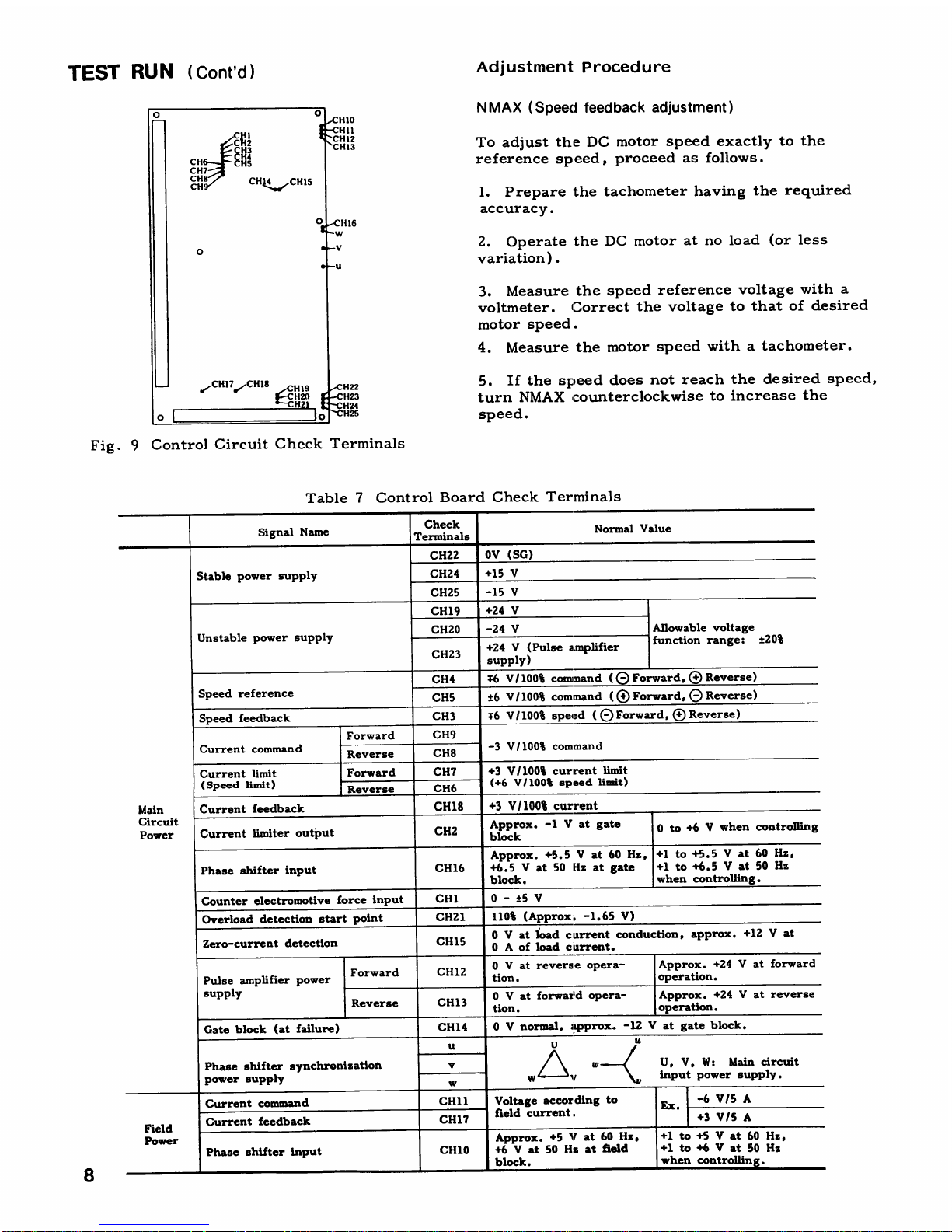
TEST
RUN
(Cont'd)
Adjustment
Procedure
Fig.9
Control
Circuit
Check
Terminals
N
MAX
(Speed
feedback adjustment)
Table7Control
Board
Check
Terminals
To
adjust
the
DC
motor
speed
exactlytothe
reference
speed,
proceedasfollows
.
1.Prepare
the
tachometer
having
the
required
accuracy
.
2.Operate
the
DC
motoratno
load
(or
less
variation)
.
3.Measure
the
speed
reference
voltage
with
a
voltmeter.Correct
the
voltagetothat of
desired
motor
speed
.
4.Measure
the
motor
speed
withatachometer
.
5
.
If
the
speed
does
not
reach
the
desired
speed,
turn
NMAX
counterclockwise
to
increase
the
speed
.
Signal
Name
Check
Terminals
Normal
Value
CH22
OV
(SG
)
Stable
power
supply
CH24
+15
V
CH25
-15
V
CH19
+24
V
CH20
-24
V
Allowable
voltage
Unstable
power
supply
CH23
+24
V
(Pulse
amplifier
supply)
function
range
:
±20%
CH4
:6
V/100%
com
mand
(8
Forward,
(+
Reverse)
Speed
reference
CH5
±6
V/100%
com
mand
((D
Forward,
(DReverse)
Speed
feedback
CH3
;6V/
100%
spe
ed
(0
Forward,
+
Reverse)
Forward
CH9
Current
command
Reverse
CH8
-3
V/100%
command
Current
limit
Forward
CH7
+3
V/100%
current
limit
(Speed
limit)
Reverse
CH6
(+6
V/100%
speed
limit)
Main
Current
feedback
CH18
+3 VI100%
current
Circuit
Power
Current
limiter
output
CH2
.-1Vatgate
ock
bl
Approx
0 t
o
+6Vwhen
controlling
Phase
shifter
input
CH16
Approx.+5.5Vat60
Hz,
+6
.5Vat50Hzatgate
block
.
+1to+5
.5Vat 60
Hz,
+1to+6
.5Vat 50
Hz
when
controlling
.
Counter
electromotive
force
input
CH1
0 - ±5
V
Overload
detection
start
point
CH21
110%
(Approx:-1
.65
V)
Zero-current
detection
CH15
0
V
at
load
current
conduction,
approx
.
+12Vat
0Aof
load
current
.
Pulse
amplifier
power
Forward
C1112
0
Vatreverse
opera-
tion
.
Approx.+24Vat
forward
operation
.
supply
Reverse
CH13
0Vat
fozwaz~d
opera-
tion
.
Approx.+24Vat
reverse
operation
.
Gate
block
(at failure)
CH14
0
V
normal,:!pprox.-12Vat
gate
bloc
k
.
u
U
u
Phase
shifter
synchronization
v
4/_~s
ar
U, V,W:
Main
circuit
power
supply
w
w
11
y
input
power
supply
.
Current
command
CH11
Voltage
according
to
~
-6
V/5
A
Field
Current
feedback
CH17
field
current
.
+3
V/5
A
Power
Phase
shifter
input
CH10
Approx.+5
Vat60
Hz,
+6Vat
50
Hzatfield
block
.
+1
to +5Vat60Hz,
+1 to
+6Vat 50
Hz
when
controlling
.
Page 9

6.If
the
speed
exceeds
the
desired
speed,
turn
NMAX
clockwise
to
decrease
the
speed
.
FLIMIT
(Forward
limit
value
adjustment)
RLIMIT
(Reverse
limit
value
adjustment)
1.Current
limitation
(Speed
control)
Slide
the
control
method
selector
switch
(1SW)
on
the
control
circuit
board
toN.
When
the
voltages
at
CH7
(forward)
and
CH6
(reverse) are+3V,
100%
current
limit
valueisobtained
.
Current
limit
value
can
be
set
within
the
range
of0%to
250%
by
F
LIMIT
andRLIMIT
.
2.Speed
limitation
(Current
control)
Slide
the
control
method
selector
switch
(1SW)
on
the
control
circuit
board
toI.
When
the
voltages
atCH7
(forward)
and
CH6(reverse)
are
+6
V,
100%
speed
limit
valueisobtained.Speed
limit
value
can
be
set
within the
range
of0%to
250%
by
F
LIMIT
andRLIMIT
.
PSB
(Phase
shifter
operating point
adjustment)
PSB
sets
the
phase
shifter
operating
point
.
1.When
the
current
controller
(ACR)
is
inte-
gral-controlled
Connect
the
plug
selectorFon
the
control
circuit
board
atFl.
Turn
PSB
fully
counterclockwise
.
2.When
the
current
controller
(ACR)
is
ratio-
controlled
Connect
the
plug
selectorFon
the
control
circuit
board
atF2.
Turn
PSB
clockwise gradually
with
reference
current
at 0V(0VatCH2),and
set
at
the
position
where
main
circuit
current
is
ready
to
start
.
CEMF
(Counter
electromotive force
compensation)
Current
loopisvulnerable
to
counter
electro-
motive
force.In
order
to
obtain
optimum
per-
formance,acompensating
electromotive
force
has
to
be
biased
on
the
phase
shifter,
depending
on
the control
mode
.
1
.
When
the
current
controller
(ACR)
is
ratio-
controlled
Adjust
CEMF,
observing
the
motor
acceleration
current withasynchroscope
.
Turn
CEMF
fully
counterclockwise,
and
turn
CEMF
clockwise
gradually
until
optimum
value
shown
in
Fig.10
is
obtained
.
2.When
the
current
controller
(ACR)
is
inte-
gral-controlled
MOTOR
ACCELERATION
CUR
1tENT
Field
Current
Adjustment
Fig
.
10
CEMF
Adjustment
CEMF
compensation
reduces
the
loss
time
due
to
Forward/Reverse
selectiontoas the
same
level
as
the
integral
control
of
ACR
.
Turn
CEMF
fully
counterclockwise,
and
during
motor
acceleration
by
current
limit
gradually
turnitclockwise
until
the voltageatCH2
on
the
control
circuit
board
stabilizes
.
Field
current
adjustment
is
required
for
checking
the
setting
at
the factory or
for
fine
adjustment
.
To
change
the
setting,
selection
of
resistors
(1FBRto
4FBR)on
the
control
circuit
board
is
required
.
1.For
constant
field
current
a
.
ConnectaDC
ammeter
to
the
field
circuit
.
b.Adjust
so
that
the
ammeter
indicates
the
rated
field
current with
IREF
on
the
control
circuit
board.(Refertothe
test
report
or
nameplate
data
.)
2.For
field
weakening
control
SYNCHROSCOPESCREEN
ADJUST
THE
SWEEP
SPEED
ADAPTED
TO
THE
MOTOR
ACCELERAITON
TIME
TO
BRING
THE
CURVES
TO
A
CONVENIENT
POSITION
.
Field
weakening
controlismade
for
the
VS-505WII
combined
with
field
weakening
control unit
type
JGSM-51-
D
.
a.Connect
DC
ammeter
to
the
field
circuit
and
DC
voltmetertooutput
terminals
P,N.
b.Turn
IREF
on
the
control
circuit
board
and
FORCE
FLD
andV
LIMIT
of
field
controller
fully
counterclockwise
.
c.Seat
the
minimum
field
weakening
current
by
IREF.In
this
case, set the
current
at
80%
field
weakening
current
at
maximum
speed
.
(See the
test
report
.)
d.Set the
rated
field
current
(field
intensifying
by
FORCE
FLD
.(See the
test
report
or
name-
plate
data
.)
e.Alter
the
motor
starts,
gradual
increasing
the
speed
reference
increases
the
voltage
across
P
andNand
governs
itatsome
value
.Turn
V
LIMIT
clockwise gradually
so
that
the
governed
valueisthe rated voltage
.
Page 10

MAINTENANCE
VS-505WIl
requires
almost
no
daily
inspection
.
To
keep
the
correct
and
successful
operation,
periodic
maintenance
operations
should
be
per-
formed.The
users
should
prepare
their
own
maintenance
programs
based
on
the
following
guidelines
.
PERIODICINSPECTION
Table8shows
the
minimum
inspection items
and
the
procedures
.
Table
8
Periodic Inspection
PARTS
REPLACEMENT
.
Replace
the
parts
required
after
checking
the
trouble
and
correcting
it
according
to
TROUBLE-
SHOOTING
GUIDE
.
.
Turn
off
the
power
before
part removal
or
mounting
.
10
Fig.11
Field
Thyrsitor
Assembly
Field
Thyristor
Replacement
With
all
the
Models,
thyristor
modules
consisting
of
a thyristor
andadiode
are
used
as the
field
thyristor.Replace
them
as
follows
.
1.Remove
the
four
mounting
screws
of
field
snubber
board
(3PCB),
lead
clamping screws,
control
power
connector
.
Then,
remove
snubber
board.See
Fig.11
.
2.Remove
lead
clamping
screws
connecting
to
thyristor,
and
remove
the leads
from
thyristor
.
In
this
case,
mark
all
terminals
for
identification
.
See
Fig.12
.
3.Remove
thyristor
mounting
screws
(2)
and
remove
thyristor
module
.
4
.
ChecktY;Ie
type
and
capacity of
new
thyristor
module
against the
requirements.Installitby
reversing
the
removal
procedure,
making
con-
nections
to
the
terminals
identifiedbythe
marks
made
before
removing
the
old
thyristor
module
.
Coat
the thyristor
mounting
surface
with
joint
compound,
JOINTAL
Z
madeby
Nippon
Light
MetalCo. ,
Ltd
.
Main
Circuit
Thyristor
Replacement
VS-505W
1,
230Vat25A
The
unit
uses
a thyristor
module
consisting
of
two
thyristors.Replace
itasfollows
.
1.Remove
snubber
board
(4PCB)
mounting
screws
(5)
and
lead
clamping
screws.Remove
snubber
board.(Fig
.
13)
2
.
Remove
bus
bar
mounting
screws
and
lead
clamping
screws
connected
to
thyristor.Remove
bus
bar
and
leads.(Fig
.
14)
In
this
case,
mark
the terminals
for
identification
.
3
.
Remove
two
thyristor
clamping
screws
and
thyristor
.
4.Check
the
replacement
module
for
type
and
capacity,
and
reinstallitby
reversing
the
dis-
assembly
procedure,
identifying the terminals
by
means
of the
marks
made
prior
to
disassembling
.
THYRISTOR
MTGSCREWS
Fig.12
With
SnubberBoard
Removed
Inspection
Part
Inspection
Item
Inspection
Procedure
Whattodo
Remarks
Thyristor
"
Noise
"
Check
for
Replace
.
Ruleofthumb
cooling
any
inter-
for
cooling
fan
fan
mittent
or
replacement
:
unusual
15,000
hours
noise
.
of
operation
.
"
Vibration"Feel
by
hand
.
-
General
"
Dust
or
.
Check
for
Clean
with
dirt
dust
clogging
an
electri-
or
dirt
cal
cleaner
"
Loose
ter-
adhesion
.
,
Tighten
.
minal
"
Check
for
screws
or
loose
screws
nuts
or nuts
.
Page 11

Main
Circuit
Thyristor
Replacement
VS-505W
1,
230Vat
35
to
105A,460Vat50to
105
A
The
unit
usesathyristor
module
consisting
of
two
thyristors.Replace
it
as
follows
.
1.Remove
snubber
board
(4PCB)
mounting
screws
(5)
and
remove
snubber
board
.
(Fig.15)
2
.
Remove
busbar
mountingscrews
and
lead
clamping
screwsconnected
to
thyristor.Remove
bus
bar
and
leads
.
(Fig
.
16).In
this
case,
mark
the
terminals
for
identification
.
3
.
Remove
two
thyristor
clamping
screws
and
thyristor
.
4.Check
the
replacement
module
for
type
and
capacity,
and
reinstallitby
reversing
the
dis-
assembly
procedure,
identifying
the
terminals
by
means
of
the
marks
made
prior
to
disassembling
.
Coat
the
thyristor
mounting
surface
with
joint
compound,
JOINTAL
Z
made
by
Nippon
Light
Metal
Co.,
Ltd
.
SNUBBER
BOARD
.TG
SCREWS
(5)
Fig
.
13
Field
Thyristor
Assembly
(230
V,
25
A)
Fig
.
14
With
Snubber
Board
Removed
Main
Circuit
Thyristor
Replacement
VS-505
W1,230Vat
180to550A,460Vat
180
to
550
A
The
VS-505WIE
usesaflat
thyristor
module
as
a
power
module
.For 180Aand
260
A,
one
power
module
is
employed,
and
for
420
A,
and
550
A,
three
power
modules
are
employed
.
Proceed
as
follows
.
1.Remove
the
clamping
screws
for
thyristor
gate
(C)
and
cathode
(K)
terminals
(24 for 260
A
or
below,
and8for
420
A
or
more),
and
free
the
leads.Remove
fuse
mounting
bolt(s)
(3 for
260
A
or
below
and1for
420
A
or
more)
.(Fig
.
17)
2.Loosen
power
module
mounting
bolts
(7
for
260Aor below,8for
420
A
or
more),and
remove
the
power
module
.
THYRISTOR
CLAMPING
-
SCREWS
S14UBBER
BOARD
MTG
SCREWS
(5)
Fig.15
Main
Circuit
Thyristor
Assembly
(460
V,
105
A)
BUSBAR-
Fig
.
16
With
Snubber
Board
Removed
Page 12

MAINTENANCE
(Cont'd
)
3.Place
the
main
circuit
thyristor
moduleon
a
work
bench
.
Remove
the
snubber
board
(4PCB-
U,
V, W) mountingscrews
(3
for
260Aor below,
4 for
420Aor
more),
and
take
out
the
snubber
board.(Fig.18)
4.Loosen
the
fin
mounting
nuts
alternately,
turning
1/4
turn
at a
time.Then,
remove
the
leaf
spring
.
5
.
Remove
the
fin
and
take
out
the
leaf
spring
.
6.Clean
the
contact
surfaces
of
the
new
thy-
ristor
and
the
fin,
and
thinly
coat
these
surfaces
with
joint
compound,
JOINTAL
Z
madeby
Nippon
Light
Metal
Co.,Ltd
.
7.Align
the
fin
locating
pin
and
the
thyristor
locating
hole, after
making
sure
that
the
polarity
of
the
thyristor
is
correct
.
8.Keeping
the
leaf
spring
and
the
fininparal-
lel,
finger-tighten
the
clamping
nuts
.
Then,
tighten
them
alternately
through
1/4
turn
at
a
time,
three
times
each
withasocket
wrench
.
Now,
the
thyristor
fin
has
been
installed
.
12
Thyristor
Protective
Fuse
Replacement
2.Remove
the
two
fuse
mounting
bolts
.
VS-505W
11,
230Vat25to
105A,460Vat50to
105
A
1.Pull
up
the
fuse
blown
indicating
microswitch
with
the
leads
connected
.(Fig
.
19)
3.Mount
the
replacement
fuse
by
reversing
the
removing
procedure,
after
checking
it
for
model
and
capacity
.
9.Tighten
the
snubber
board
mountingscrews
.
Then,
mount
the
thyristor
module
by
reversing
thedisassembling
procedure,
tightening
the
screws
firmly
.
THYRISTOR
GATE
(G)
CATHODE
(K)
TERMINALS
FUSE
K
(RED)
G
(WHITE)
THYRISTOR
681-193
(a)
With
Thyristor
Removed
Fig.18
Thyristor
Replacement
(b)
Thyristor
Fig.17
Main
Circuit
Thyristor
(460
V,
420
A)
Fig.19
Main
Circuit
Fuse
Assembly
(460
V,
105
A)
Page 13

Thyristor
Protective
Fuse
Replacement
VS
-505W
1,
230Vat
180
to
550A,460Vat
180
to
550
A
1 .
Remove
the
two
lead
clamping
screws
of
the
fuse-blown
indicating
mocroswitch
and
free
the
leads
.
(Fig
.
20)
2.Remove
the
two
fuse
mounting
bolts,
and
remove
the fuse
together
with
the
fuse-blown
indicating
microswitch
.
3.Check
the
replacement
fuse
for
model
and
capacity,
and
installitby
reversing
the
disas-
sembling
procedure
.
Surge
Absorber
Fuse
Replacement
Surge
Absorber
Replacement
Fig.20
Main
Circuit
FuseAssembly
(460
V,
420 A)
1.Pull
the
fuse
element
and
removeit.
(Fig.21)
2.Mount
the
replacement
fuse,
after
checking
its
model
and
capacity
.
Fig.21
Surge
Absorber
Fuse
1.Remove
three
surge
absorber
mounting
screws
and
remove
surge
absorber
.
2.Check
the
replacement
surge
absorber
for
model
and
capacity.Mount
three
surge
ab-
sorbers
after
connecting
M4
pressure
termi-
nalstotheir leads
as
shown
in
Fig.22
.
IL
)k,
Thyristor
Cooling
Fan
Replacement
Fig.22
Surge
Absorber
with
Pres-
sure
Terminals
Connected
to
Leads
To
replace a thyristor
cooling
fan
withanew
one,
proceed
as
follows
.(Fig.23)
The
VS-505WIL
unitsrated
230
V,
25A;
460
V,
50Aare
self-
cooled
type
.
1
.Remove
the
cooling
fan
power
lead
.
2.Unscrew
the
two
fan
mountingscrews
and
dismount
the fan
.
3.Remove
the fan
by
reversing the
disassembl-
ing
procedure
.
(a)
230
V,
45to105
A;460
V,
90/105
A
FAN
POWER
SUPPLY
LEADS
(2)
r
.
.
(b)
230
V,
180/260A;
460
V,
180/260
A
(c)
230
V, 420/550A;
460
V,
420/550
A
Fig
.
23
Thyristor
Cooling
Fan
1
3
Page 14

MAINTENANCE
(Cont'd
)
Control
Circuit
Board
Replacement
Disconnect
all
the
leads
from
the
terminals
.
Then,
unplug
the
connectors
shown
in
Fig
.
24,
and
remove
the
6
control
circuit
board
mounting
screws
.
Mount
the
new
board
by
reversing the
disassembling
procedure
.
Plug-in
the
connectors
firmly
.
CAUTIONS
IN
REPLACING
CONTROL
CIRCUIT
BOARD
TROUBLESHOOTING
GUIDE
1
4
EXTERNAL
CONTROL
TERMINALS
FUSE-BLOWN
DETECTION
CONNECTOR
CURRENT
DETECTION
CONNECTOR
Make
sure
that
the
typeofthe
new
control
circuit
board
agrees
with
the
nameplate
and
potentiometer
settings of
new
control
circuit
board
are the
same
as the old
one.Refertothe
nameplate
"CautionsinOperation"
postedonthe
inside of
the
control
circuit
board
doorofVS-505WII.See
Table6"Adjuster
Locationsonthe Control
Circuit
Board
and
Functions"
.
Fig.24
Control
Board
Table
9
Troubleshooting
Guide
Note:If
the
readingisnot
m
.
accurate
measurement
with a
500Vmeggerisrequired
.Reading
must
be3megohms
or
above
.
Trouble
Possible
cause
Check
method
Whattodo
PREP
lamp
Control
Failure
indicating
OFF
printed
lampON.
board
Operation
sequence
Check
the
external
operation
sequence
._Replace
the
control
board.See
Replace-
failure
.
mentofControl
Board
.
OCL
lamp
Control
Too
low
setting
of Is setting
dial at
the positions
indicated
Set the setting
dialtothe
ON
printed
"OL%,"
"OLT"
.
b
lock
"
dint?
position of lock
dint
.
board
Too
high
setting of
"FLIMIT,"
"RLIMIT"
RefertoTables
6and 7
.
Incorrect
setting of
Readjust
.
"IFB'
:
Thyristor
Defective
deterto-
Check
thyristor
(Fig.25)
.
Replace
thyrtstor.(See
Main
rated)
.
CircuitThrtstoronpage
9.)
Motor
and
Overloaded
.
Check
load
current
.
A
iust loa
.
Reset
.
driven
Locking
.
Run
motor
without
load,
and seeifit
locks
Repair
motor
.
machine
Check
load for
locking
.
Layer
shorting
in
Run
motor
with
terminalsPandNdis-
Repair
motor
.
motor
.
connected.If
OCL
lamp
does
not
light,
the
motor
and
its
circuit
are
defective
.
Grounding
of
motor
Measure
resistance
between
terminal
P)
"
Repair
motor
.
circuit
.
(or N)
and
ground
(E)
with
a multitester."
Correct
wiring
.
If
the
reading
is
nearly-on
the
largest
scale of the tester,
the
circuitisnormal
.
U
lamp
Thyristor Defective
deterto-
Check
thyrtstor
(Fig.25)
Replace
thyrtstor.(See
Main
Circuit
ON
r
ated)
.
Th
rtstoronpage9.
Motor Layer
shorting
in
Operate
only
board
with
(P)
and
(NT
-1-
s-
Repair
motor
.
motor
.
connected.If
fuseisnot
blown,
motor
circuit
is
defective
.
Groundingofmotor
Measure
resistance
across
terminal
I'
or"repair
motor
.
To
replace
circuit
.
N)
and
ground
(E)
with
a multitester,
and"Correct
wiring
.
fuses (1FU,
if
the
readingisnearly
m
on
the
largest
ZFU.5FU),
scaleofthe
tester, the
circuit
is
normal
.
refer
to
o
(See
Note
.)
Replacement
t
;
Control
Defective
phase
Ifthemotor
isnormal.replace
of
Thyristor
circuit
control
circuit)
.
control circsut
board.Refer
Protection
"
O
board
to
ReplacementofControl
Fuse
.
c
Circuit
Board
on page13.
c
Fuse
Defective
deterio-
rated)
.
_
FL
lamp
Motor Layer
shorting
in
Measure
resistance
across
terminal J
and
"
Repair
motor
.
ON
field
winding
.
K
with
converter
terminal J
andKdis-
"
Replace
fuse.(3FUor4FU)
.
connected
withatester.If
it
indicates
m,
it
means-
field
circuitisdisconnected
.
Groundingoffield
Measure
resistance
across
terminal
(.Ior
K
circuit
.
andground
(E)
with
a multitester,
and
if
the
readingisnearlymon
the
largest
scale of the tester,
the
circuitisnormal
.
Control
Defective
.
If
the
motorisnormal,
replace control
[board
circuit
board.See
ReplacementofControl
Boardonpa_e 13
.
THG
lamp
Motor
Over
Main
circuit
Check
load
current.'
Ad
ust load
.
ON
loading.Field
circuit
Check
field
current
.
Head
ust.See
Adjustment
on
page
7 .
Locking
.
Run
motor
without
load,
and see
if it
locks.Reitmotor
.
Check
load for lockmf-
.-,
.
A
.'
_'J
.
Blocked
air filter
.
Refer
to the
instructions
for Industrial
DC
Motors
(TOE-C435-3)
.
Insufficient
cooling
Check
the
blower
for
correct
running
Correct
wiring
.
with
blower
.
direction
.
MCF
lamp
Motor
Cooling
blower
stop.Check
fan
for
lockingoroverloadinE
; .
Repairor
replace
fan
.
ON
_Check
thermal
relay
for
tri..in
TCF
lamp
Thyristor
cooling
an stop
.
Check
fan for
locking
or
overloading
.
Replace
the
thyristor
cooling
fan.See
ON
Where
the
fanisprovided
with
Replacement
of
Thyristor
Cooling
Fan,
failure
sensor
on page12.
Surge
Main
CKT
Excessive
surge
.
Check
fuses
3FU,
4FU
.
Eliminate
causeofsurge.Replace
surge
absorber
and
fuse.See
ReplacementofSurge
of
fuse
blown
Absorber
Fuse
and
Replacement
of
Sure
Absorber
.
Page 15
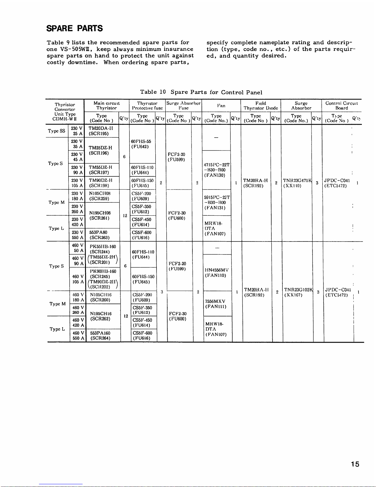
SPARE
PARTS
Table9lists
the
recommended
spare
parts
for
one
VS-505WII,
keep
always
minimum
insurance
spare
parts
on
hand
to
protect
the
unit
against
costly
downtime
.
When
ordering
spare
parts,
Table
10
Spare
Parts
for
Control
Panel
specify
complete
nameplate
rating
and
descrip-
tion
(type,
code
no
. ,
etc.)of
the
parts
requir-
ed,
and
quantitydesired
.
Thyristor
Main
circuit
Thyristor
Surge
Absorber
Fan
Field
Surge
Control
Circuit
Converter
Thyristor
Protective
fuse
Fuse
Thyristor
Diode
Absorber
Board
CI)MlTWII
Type
(~'tyType
Q,ty
Type
I
Q~ty
Type
Q.ty
Type
Q,ty
Type
Q.tY
T%pe
Q
'
t -
`
(CodeNo)
(CodeNo)
(Code
No
)
(CodeNo.)
(Code
No)
(CodeNo.)
(Code
No)
TypeSS
230VTM20DA-II
25A(SCR195)
230
V
60FHS-55
35
A
TM25DZ-H
(FU642)
230
V
(SCR196)
6
FCI"2-20
45
A
(FU599)
Type
S
230
V
TM55D7,-H
60FIIS-110
I
4715I'C-22T
90A(SCR197)
(FU644)
-1330-1300
'
(FAN130)
'
230VTM90D/
.-1-1
60FIIS-150I2
.~
1
TM20RA-Ii
2
'I'NR23G471'3
JPDC_
C041
I
105A(SC1?198)
(FU615)
(SC
IZ192)
(XX110)
(FTCa1
;2)
230VN105CH08
CS5F-200
-~
M
180A(SCR259)
(FU609)
I
59151'C-22T
Type
230
V
CS5F-350
-1330-13tH)
(FAN
131)
,
260
A
N195CH08
(FU612)
FCF2-30
230
V
(SCR261)
12
CS5F-450
(FU600)
L
420
A
(FU614)
MlI
.W18-
Type
230
V
553PA80
CS5F-600
(FAN107)
550A(SCR263)
(FU616)
460
V
PK55IIB-160
-
50
A
(SCR244)
60FIiS-110
460
V
rI'M55DZ-21i
(FU644
)
90
A
1(SCR201)
PCF2-20
Type
S
6
PK90HB-160
(FU599)
HN4556MV
460V(SCII245)
60FHS-150
(FAN110)
'
105A(TM90Dl,-211
(FU645)
\(SCH202)
'
TM20IZA-l1
TNR23GIO2
'
J1'DC-CO-11
3
1
2
3
1
.160VN105CI116
CS5F-200
(SCR192) (X
X167)
(ETCa172)
;
M
180A(SCR260)
(FU609)
7556MXV
Type
460
V
CS5
F-350
(FANI
11)
2(i0
A
N195CII16
12
(FU612)
FCF2-30
j
460
V
(SCR262)
CS5F-450
(FU600)
i
L
420
A
(
FU614
)
MRW18-
Type
460V553PA160
CS5F-600
(fTAN107)
550A(SCR264)
(FU616)
i
Page 16

(REFERENCE)
ROUGH
CHECK
OF
THYRISTORS
Where
thyristors
normally
function,
the
following
values
are
obtained
.
More
than
several
hundreds
of
kiloohms
across
Several
ohms
to
several
hundreds
of
ohms
across
(A)
and
(K)
.
(G)
and
(K)
.
IPA
RPA
1
6
FS
FT
(a)
Resistance
across
thyristor
(b)
Resistance
across
thyristor
terminals
(A)
and
(K)
terminals
(G)
and
(K)
ELEMENTARY
DIAGRAM
OF
THYRISTOR
CONVERTER
UNIT
(TYPE
CDMR-W
II,
230V,
90A)
P15
RT=4-p
18
P19,
P20
1PCB
G1
K1
K2
G2
G1
K1
N3,4
Y
1,
Y5
I
R1
Il
R
.)
JPDC-P05()
FPA~
,
RPA
i
G1
Thyristor
fails
i
f 0or-isin-
dicated
on the
even
either
tester
(x
1
0
range)
Fig
.
25
Rough
Check
of
Thyristors
AC
POWER
SUPPLY
200/220V 50/60Hz
-----------
~----------
Fig.26
Main
Circuit
500W1500
Thyristor
fails
if
0 or-is
in-
dicated
on
the
even
either
tester(x1
S2
range)
CONTROLLER
JPDC-CO41
R
1PCB
Page 17

HALT
._27
PREPARATION
O
STOP0RUN
9
FLD
ROCK
Flu
(MCF)
FuH
TCFH
DCTG
20
-
3+0
nv/
I(X)%
uw/
I(X)%
15v/
I(X)%
SPFEO
REFERENCE
FROM
CONTROL
TRANSFORMER
6
-P.0V
-
+48V
LOGIC
CIRCUIT
+15VOV
-15V
(P)
23
CONTACT
RATING
220VAC2A
24
VDC
2A
RUN
M-ON
COM
'FLD
CONT
PREPARATION
:
i{----------
_
L
4
JGSM-519}T~-
6131415
__l-i
_i
pno
20,NAOU
LT
CUM
NC
4 51 52 49
©I2
3a
s
©
FBR
OCL
IREF
-
-24V
Fig
.
27
Control
Circuit
ESE
CHIT
CH17
ACR
7,
FK
50Hz4y60Hz,
NH1
REVERSING
CONTROL
LER
ZC
0
CH15
PS
llms
llms
A
S
FBR
aoaa
10
SELECTOR
SWITCH
nnn
!ij4dj
I
IFLDIFB
CH12
CH13
1Q
v
TYPE
:JPDC-CO41
Z
~TF
FPA
RPA
RT
QRFI
FROM
POWER
PCB
H
FROM
POWER
PCB
H
Page 18

(REFERENCE)
(Cont'd)
FUNCTIONS
OF
EXTERNAL
CONTROL
TERMINALS
1
8
Table
11
Functions
of
External
Control
Terminals
for
Input
Notes
1.Use
highly
reliable
contact
for
input
interface
signal
considering
that the
load
is 48
VDC,
10
mA
.
2.Provideanoise
killer at
both endsofcoil
when
relays,
contactors,
etc.are
used
.
Signal
Name
Terminal
Function
1
Ready
signal
-
-°
0-
30
"Close" --- Field
intensifying
.
"O"men"
---
Gateblock+Field
half-reduced
.
2
Operation
signal
29
"Close"
---
Speed
reference
"ON"-;
Accelerationtospeed
--0
reference
value
.
"Open"
---
Speed
reference
"OFF"-Stop
by
regenerative
braking+Gate
block
.
29
"RUN"
---
Speed
reference
"ON"-}Accelerationtospee,
"
reference
value
.
j j
28
"STOP"
---
Speed
reference
"OFF"-"
Stop
by
regenerative
~
braking-Gate
block
.
3
Quick
stop
27
Quick
stopat'
Close'incaseofsoft
start
operation
.
signal
-o
o-
"Close"
---
Speed
reference
"OFF"-}Stop
by
regenerative
braking-rGate
block
.
4
Main
circuit
M
2 "Close" ---
Gate
block
Terminals
26
and
35
(or
36)
input
answer
back
~
0-
released
.
short-circuited
unless
used
.
signal
5
Motor
overheat
33
"Open"
---
Gate
block
.
si
nal
- -
"Close" ---
Normally
.
"
Field
block
signal
3 "Close"
---
Fie143
block.(Field
circuit
clipped
at
PP
-°
°-
phase
.)
7
Motor
blower
31
"Close"
---
Field intensifying
.
ON
/OFF
signal °-
"Open"
---
Gate
block-~Field
currenthalf-reduced
.
8
External gate
_
4-47
"Close"
---
Gate
block
.
block
signal
9
External
(OCL)
45 -
46
"Close"
---
Normally
.
Terminals
45
and4"
short-
failure
reset
~~-
"Open"
---
Reset
.
circuited
when
reset
button
in
the
unitisused
.
10
Fuse
blown
R1-R2
"Open"
---
Normally
.
detection
signal
"Close"
---
Gate
block
.
(inside)
11
Thyristor
cooling
R3-R4
With
failure
detection
cooling
fan
(option)
.
fan
stop
signal
__0
"Open"
---
Normally
.
(inside)
"Close" ---
Gate
block
12
Speed
reference
t&
V
/100$N
"
Soft
start
commnw
"
-"zei~~z:e
.
(0+Forward,
(D
7
-4
V
'100
""
"3to 75
(Variable)
Reverse)
8 ±10V/100%N
sec
.
9
f15
7100%N
Accel.time, decel.time
ad-
10
0
V
(SG)
justable
independently
.
12
*6V/
100$N
Terminals
11
an,.1
short-
circuited
.
13
±6V/100
0
/6N
13
External
current
reference
(
(D
14 ±3
V/100%
Ia
Forward
torque,
0
Reverse
15 0
V
(SG)
torque)
14
Speed
feedback
-
DCTG
2 3
(+)
signal
15
CEMF
compensation
48
Forward
:4V/1U0%
Va
Reverse:+6
V/100%Va
1
"
Automatic
field
1
Output
received from
field
controller
TypeJGSM-51
.
weakening
current
command
17
Speed
feedback
5
"
Output
from
TypeJGSM-
5
(Voltage
feedback)
When
reversible
operation
by
ACTG.(OPN:Open)
"
Output
fromtype
JGSM-53
When
speed
controlled
by
voltage
detection
.
(OPN:OP
,
en)
Page 19

Table
12
Functions
of
External
Control
Terminals
for
Output
*Allowable
rating 24
VDC,
50mA.(24
VDC
power
supply
required
externally
.)
Signal
Name
Terminal
Function
1
Ready
signal 24 - 25
Contact
signal
closed
when
.
.-0
operationisready
.
Allowable
contact
(PREP
lightON.)
capacity
2
Operation
signal
zz
3
21-22-23
NO
contact
----
For
input
220
VAC,2A
o- c
ommand
.
24
3 Failure signal
19~~
18-19-20
Contact
signalcose"or
VDC,
2
A
0-1
-
°
opened)
when
failure
occurs
.
4
Zero-speed
44
"ON"
at
motor
speed
1% or
below
(±6
V/100%
NPB)
.
detectionsin
al
5
Main
circuit
current
detec-
49
-
V
100
Ia
tion
signal
(Allowable load
impedance:3
k9Z)
±12VMax
6
Speed
reference
signal
11
-6
V/100%
N
Terminals
11an(A
12
short-circuited
.
7
Speed
feedback
signal
4
Input
from
Type
JGSM-
when
revers1peoperation
b
ACTG
. (
OPN:Open)
8
Indi-
Thyristor
cooling
39
"ON"
by
thyristor
cooling
vidual
fan
stop
fan
stop
.
failure
Thyristor
overcur-
40
"ON"
by
thyristor
overcur-
detec-
rent
and
overload rent
overload.
tion
Field
lost
41
"ON"
b
fieldloss
.
signal
Motor
overheat
42
"ON"
b
motor
overheat
.
Fuse
blown
43
"ON"
b
fuse-blown
.
9
Speedometer
50-1
Connected
to1mA
DC
meter
(2kQor
below)
.
(Full
scaleat_
maximum
speed)
10
Main
circuit
ammeter
-
1
Connected
to
1
mADC
meter
(2kQor
below)
.
(Full
scaleat150%
load)
11
Control
power
supply
53
-15
V
54
0V(S
G)
55
+15
V
38
+24
V
37 0V(
POWER
0
V
~~
EP
+48
V
Isolate(A
from
other
34
V
POWER
TV
control
r,rpr~C-~1~1y
.
Page 20

Varispeed-505NA/II
INDUSTRIAL
USE
THYRISTOR
CONVERTER
UNITS
TOKYO
OFFICEOhtemachi
Bldg,
1-6-1
Ohtemachi,
Chiyoda-ku,
Tokyc,
100
Japan
Phone
(03)
3284-9111Telex
YASKAWA
J33530Fax
(03)
3284-9034
SEOUL
OFFICESeoul
Center
Bldg,
91-1,
So Kong-bong,
Chang-ku,
Seoul,
Korea
Phone
(02)
776-7844Fax
(02)
753-2639
TAIPEI
OFFICEShen
Hsiang
TangSung
Chiang
Building
10F146
Sung
Chiang
Road,
Taipei,
Taiwan
Phone
(02)
563-0010,
-7732Fax
(02)
567-4677
YASKAWA
ELECTRICAMERICA,
INC
. -
SUBSIDIARY
Chicago-Corporate
Headquarters
2942
MacArthur
Blvd
Northbrook,
Illinois
60062-2028,USA
Phone
(708)
291-2340Fax
(708)
498-2430
Chicago-TechnicalCenter
3160
MacArthur
Blvd
Northbrook,
Illinois
6()062-1917,US
A
Phone
(708)
291-0411Fax
(708)
291-1028
Los
Angeles
Office5626
Corporate
Avenue
Cypress,CA90630,US
A
Phone
(714)
828-9692
Telex (230)
678396
YASKAWAUSTSTN
Fax
(714)8'8-1165
New
Jersey OfficeRiverdale
One,44Route23North, Suite 5
Riverdals,NJ
07457-1619
Phone
(201)
835-9512Fax
(201)
835-9511
YASKAWA
ELECTRIC
EUROPE
GmbH
SUBSIDIARY
Niederhochstadter
Strafle
73,
W
61476
Kronberg-Oberhochstadt
.
Germany
Phone
(06173)
938-0Telex
415660
YASEDFax
(06173)
68421
YASKAWA
ELETRICO
DO
BRASIL
COMERCIO
LTDA
. -
SUBSIDIARY
Rua
CondeDoPinhal
8-5',
Andar
Sala51CEP
01501-Sao
Paulo-SP,
Br'Esil
Phone
(011)
35-1911Fax
(011)
37-7375
YASKAWA
ELECTRIC
(SINGAPORE)
PTE.LTD
.
CPF
Bldg,79Robinson
RoadNo13-05,
Singapore
0106
Phone
2217530
Telex
(87)
24890
YASKAWA
RSFax
(65)
224-5854
YASKAWA
YASKAWA
ELECTRIC
CORPORATION
TOE-S505-20C
®
PrintedinJapan
October
1993
63-405TA
682-215
 Loading...