

Page 1

Models: MV and CIMR-V7* Document Number: IG.V7.01
V7 and V74X Drives
Installation Guide
Page 2

WARNINGS, CAUTIONS, INSTRUCTIONS
WARNING
WARNING
YASKAWA manufactures component parts that can be used in a wide variety of industrial applications. The selection and
application of YASKAWA products remain the responsibility of the equipment designer or end user. YASKAWA accepts no
responsibility for the way its products are incorporated into the final system design. Under no circumstances should any
YASKAWA product be incorporated into any product or design as the exclusive or sole safety control. Without exception, all
controls should be designed to detect faults dynamically and fail safely under all circumstances. All products designed to
incorporate a component part manufactured by YASKAWA must be supplied to the end user with appropriate warnings and
instructions as to that part’s safe use and operation. Any warnings provided by YASKAWA must be promptly provided to the
end user. YASKAWA offers an express warranty only as to the quality of its products in conforming to standards and specifications published in the YASKAWA manual. NO OTHER WARRANTY, EXPRESS OR IMPLIED, IS OFFERED. YASKAWA
assumes no liability for any personal injury, property damage, losses, or claims arising from misapplication of its products.
• Do not connect or disconnect wiring while the power is on. Do not remove covers or touch circuit boards while
the power is on.
• Before servicing, disconnect all power to the equipment. The internal capacitor remains charged even after the
power supply is turned OFF. Status indicator LEDs and Digital Operator display will be extinguished when the DC
bus voltage is below 50 VDC. To prevent electric shock, wait at least 5 minutes after all indicators are OFF.
• Do not perform a withstand voltage test on any part of the unit. This equipment uses sensitive devices and may
be damaged by high voltage.
• The drive is not suitable for circuits capable of delivering more than 18,000 RMS symmetrical amperes at 250V
maximum or 480V maximum. Install adequate branch short circuit protection. Refer to page 13. Failure to do so
may result in equipment damage and/or personal injury.
• Input Fuses are required for proper branch short circuit protection for all NEMA type 4X/12 drives. Failure to use
recommended fuses (See Appendix 4) may result in damage to the drive and/or personal injury.
2
Page 3

WARNINGS, CAUTIONS, INSTRUCTIONS
For Enclosed wall-mounted type (NEMA type 1)
When mounting units in an enclosure, remove the top, bottom and terminal covers. Install a cooling fan or
some other means to maintain the air entering the enclosure below 113°F (45°C).
For Water and dust tight type (NEMA type 4X/12)
Never submerge this model in water. For the cable lead-in section, use a waterproof cable gland. After
completion of wiring, mount the front cover and bottom cover with care so as not to damage the gasket.
The front cover mounting screws and bottom cover mounting screws are made of stainless. Replacements
must be of stainless steel and the same length.
IMPORTANT
• Wiring should be performed only by qualified personnel.
• Verify that the rated voltage of the Drive matches the voltage of the incoming power.
• Some drawings in this manual are shown with the protective covers and shields removed, in order to describe
detail with more clarity. Make sure all covers and shields are replaced before operating this product.
• This manual may be modified when necessary because of product improvement, modification, or changes in
specifications.
• YASKAWA is not responsible for any modification of the product made by the user, doing so will void the warranty.
3
Page 4

Intentionally left blank
4
Page 5

CONTENTS
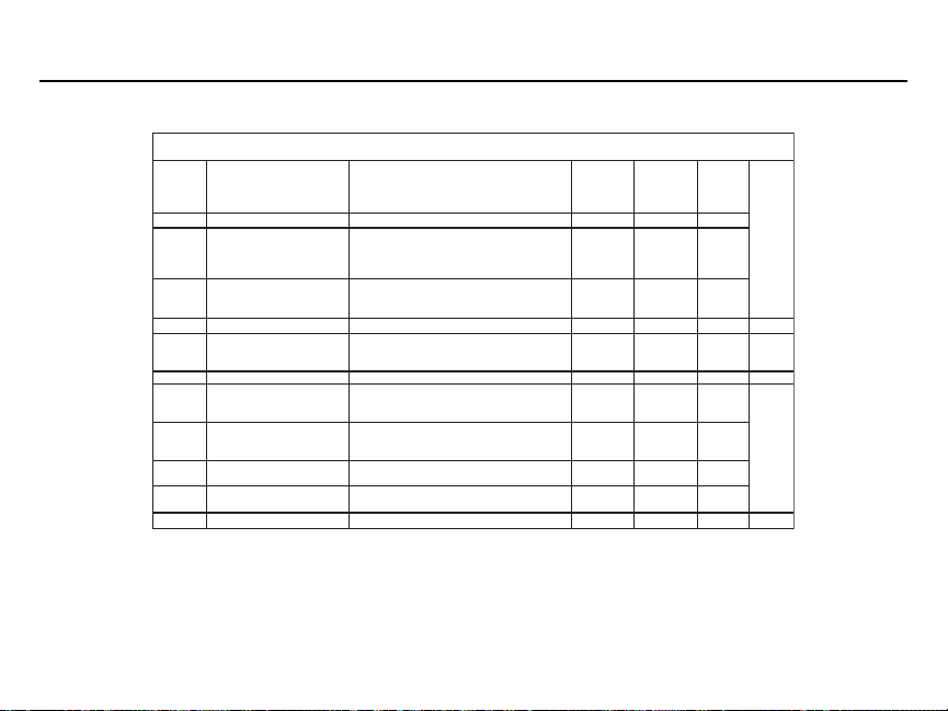
SECTION DESCRIPTION PAG E
1 Drive Specifications.................................................................................................... 6
2 Preliminary Inspection ............................................................................................... 11
Introduction................................................................................................................. 11
Receiving .................................................................................................................. 11
Nameplate Structure ................................................................................................. 12
Model Number Structure ........................................................................................... 13
Drive Spec Structure ................................................................................................. 15
3 Mounting Precautions ............................................................................................... 16
4 Wiring: Main and Control Circuit ................................................................................ 18
Main Circuit Input/Output Wiring ................................................................................ 18
Control Circuit ........................................................................................................... 18
Wiring: Grounding ..................................................................................................... 20
Wiring: Wire and Terminal Screw Sizes .................................................................... 21
Wiring: Terminal Functions and Voltages .................................................................. 22
5 Peripheral Devices ..................................................................................................... 24
Recommended Short Circuit Protection..................................................................... 24
Auxiliary Input/Output Power Option Devices ............................................................ 26
6 Conformance to European EMC Directive ................................................................ 28
7 Interconnection Precautions and Diagrams .............................................................. 30
Interconnection Diagram: 2-Wire Control .................................................................. 32
Interconnection Diagram: 3-Wire Control .................................................................. 34
8 Drive Parameter Listing ............................................................................................. 36
9 Monitor Displays ........................................................................................................ 50
10 Drive Dimensions ...................................................................................................... 52
5
Page 6

Drive Specifications Section 1
230V Class
Model CIMR-V7* 20P1 20P2 20P4 20P7 21P5 22P2 23P7 25P5 27P5
Max. applicable motor output
HP
(1)
Drive capacity (kVA) 0.3 0.6 1.1 1.9 3.0 4.2 6.7 9.5 13
Rated Output Current (A) 0.8 1.6 3.0 5.0 8.0 11.0 17.5 25 33
Output
Rated Input Current (A) 1.1 1.8 3.9 6.4 11.0 15.1 24.0 33.0 39.6
Max. Output Voltage (V) 200 to 230V (proportional to input voltage)
Characteristics
Max. Output Frequency (Hz) 400 Hz (programmable)
Rated Input Voltage and
Frequency
Allowable voltage fluctuation -15% to +10%
Power
Supply
Allowable frequency fluctuation ±5%
Cooling Method
istics
(QTY) NEMA 4 self self self self fan fan fan self self
Physical
Character-
460V Class
SECTION A.
MV A001 A002 A003 A005 A008 A011 A017 A025 A033
NEMA 1 self self self fan fan fan fan fan(2) fan(2)
Model No. Related Specifications
1/8 1/4 1/2
3/4
2357.510
and 1
3-phase. 200 to 230 V, 50/60 Hz
(5)
Model CIMR-V7* - - 40P2 40P4 40P7 41P5 42P2 43P7 45P5 47P5
Max. applicable motor
output HP
Drive capacity (kVA) - - 0.9 1.4 2.6 3.7 4.2 7 11 16
Rated Output Current (A) - - 1.2 1.8 3.4 4.8 5.5 8.6 14.8 21
Output
Rated Input Current (A) - - 1.6 2.4 4.7 7.0 8.1 12.0 19.6 27.8
Characteristics
Max. Output Voltage (V) 380 to 460V (proportional to input voltage)
Max. Output Frequency (Hz) 400 Hz (programmable)
Rated Input Voltage and
Frequency
Allowable voltage fluctuation -15% to +10%
Power
Supply
Allowable frequency fluctuation ±5%
Cooling Method
istics
Physical
(QTY) NEMA 4 - - self self self fan - - fan self self
Character-
MV - - B001 B002 B003 B005 - - B009 B015 - -
(1)
- - 1/2 3/4 1&2 3 3 5
3-phase. 380 to 460 V, 50/60 Hz
NEMA 1 - - self self self fan - - fan fan(2) fan(2)
7.5 &
10
(6)
15
(6
(6
(6
6
Page 7

SpecificationsSection 1
Drive
Control method Sine wave PWM (V/ f Control or Open Loop Vector)
SECTION B.
Frequency control range 0.1 to 400 Hz
Frequency accuracy Digital command: ±0.01% (14 to 122°F, -10 to +50°C)
(temperature change) Analog command: ±0.5% (77°F ± 18°F, 25°C ± 10°C)
Speed Regulation
Frequency setting resolution 0.1 Hz (100Hz or more)
Output frequency resolution
Overload capacity 150% of rated output current for 1 minute
Frequency Reference Signal
Accel/Decel Time
Control Characteristics
Braking Torque
V/f characteristics Custom V/f pattern
0 to 10VDC (20kΩ), 4 to 20mA (250Ω), 0 to 20mA (250Ω) pulse train input,
All Drives
Open Loop Vector: ±0.2%
V/Hz Mode: ±0.5% – 1% with Slip Compensation
Digital Operator reference: 0.01 Hz (< 100Hz)
Analog
reference: 0.06Hz/60Hz (1/1000)
0.01 Hz
Digital Operator Pot
(accel/decel time are independently programmed)
Continuous regenerative torque: Approx. 20% (150% with
optional braking resistor, braking transistor built-in)
0.01 to 6000 sec.
Short-term average deceleration torque (2)
0.2kW: 150%
0.75kW: 100%
1.5kW: 50%
2.2kW or more: 20%
See notes at end of table
(table continued on next page)
7
Page 8

Drive
Specifications Section 1
Motor overload protection Electronic thermal overload relay
Instantaneous overcurrent
Overload
Overvoltage
Undervoltage
Momentary Power Loss
Heatsink overheat Protected by electronic circuit
Protective Functions
Stall prevention level
Ground fault Protected by electronic circuit (overcurrent level)
Power charge indication RUN lamp says ON or digital operator LED stays ON.
Cooling Fan Fault Protected by electronic circuit
Run/stop input 2-Wire or 3-Wire
Multi-function input
Input signalsOutput signals
Other Functions
Multi-function output (output frequency or set value), during overtorque detection,
8
Analog monitor 0 to +10VDC output, programmable for output frequency or output current
SECTION B.
All Drives (Continued)
Motor coasts to stop at approx. 250%
Motor coasts to stop after 1 min. at 150% of
Motor coasts to stop if DC bus voltage exceeds
Motor coasts to stop when DC bus voltage is
210VDC or less (230V), 400VDC or less (460V)
• Not provided (stops if power loss is 15 ms or longer)
• Automatic restart at recovery from 0.5 sec. power loss
Independently programmable during accel and
constant-speed running. Selectable during decel.
ON until the DC bus voltage becomes 50V or less.
Seven of the following input signals are selectable:
Forward/reverse run (3-Wire sequence), fault reset,
external fault (NO/NC contact input), multi-step speed operation,
external baseblock (NO/NC contact input, speed search command,
accel/decel hold command, LOCAL/REMOTE selection,
communication/control circuit terminal selection,
emergency stop fault emergency stop alarm
(1 NO/NC contact output, 2 photo-coupler outputs):
Fault, running, zero speed, at frequency, frequency detection
during undervoltage detection, minor error, during baseblock, operation mode,
inverter run ready, during fault retry, during UV, during speed search,
of drive current
drive rated current (7)
410VDC (230V), 820VDC (460V)
The following operations are selectable:
• Automatic restart
(Charge LED is Provided for 400V)
Jog command, accel/decel time select,
Following output signals are selectable
data output through communication
Page 9

SpecificationsSection 1
Drive
SECTION B.
Standard functions
Status indicator LEDs RUN and ALARM LEDs provided as standard
Digital Operator
Display
Other Functions
Terminals Screw terminals for both main circuit and control circuit
Wiring distance between
drive and motor
Enclosure Open Type/NEMA type 1/NEMA type 4X/12
Cooling method Self-cooling/cooling fan
Ambient temperature 14 to 104°F (-10 to 40°C)
Humidity 95% RH or less (non-condensing)
Storage temperature
Location Indoor (free from corrosive gases or dust)
Elevation 3,280 feet (1,000 m) or less
conditions
Environmental
Vibration
NOTES:
(1)
Based on an N.E.C. standard 4-pole motor for max.applicable motor output.
(2)
Shows deceleration torque for an uncoupled motor decelerating from 60 Hz in 0.1 seconds.
(3)
Contact Yaskawa for wiring distances greater than 328 ft. (100 m).
(4)
Temperature during shipping (for short periods of time).
(5)
On NEMA type 4X/12 model only, maximum continuous rating of 30.8 A is 40 degrees C maximum ambient. For 33.0 A maximum
continuous rating, maximum ambient is 32 degrees C.
(6)
Applies to NEMA type 4X/12 model only.
(7)
On Model 47P5 NEMA type 4X/12 (21A), overload is 120% for 1 minute.
(4)
All Drives (Continued)
Open Loop Vector Control, full-range automatic torque boost, auto restart,
upper/lower frequency limit, DC injection braking current/time at start/stop,
frequency reference gain/bias, prohibited frequencies,
analog meter calibrating gain, S-curve accel/decel, slip compensation,
MODBUS communications (RS485/422, Max. 19.2K bps),
frequency reference from digital operator pot
Monitors frequency reference, output frequency,
output current, FWD/REF selection
328 ft (100 m) or less
-4 to 140°F (-20 to 60°C)
Up to 1G, at less than 20 Hz;
up to 0.2G, at 20 to 50 Hz
(3)
9
Page 10

Intentionally left blank
10
Page 11

Preliminary
InspectionSection 2
Introduction
This document pertains to the V7 ac drive. This document is equally applicable to drives identified as GPD315, GPD315/V7,
GPD315/V74X, and V74X. Additionally, in this document, the word “drive”, “ac drive”, and “inverter” may be used interchangeably. The V7 (NEMA type1) and V74X (NEMA type 4X/12), hereafter referred to as the "Drive," are general purpose sinecoded pulse width modulated AC motor drives which generate an adjustable voltage/frequency three phase output for complete speed control of most conventional squirrel cage induction motors. Automatic stall prevention and voltage boost prevent
nuisance tripping during load or line side transient conditions. The Drive will not induce any voltage line notching distortion
back to the utility line, and it maintains a displacement power factor of not less than 0.98 throughout its speed range.
When properly installed, operated and maintained, the Drive will provide a lifetime of service. It is mandatory that the person
who operates, inspects, or maintains this equipment thoroughly read and understand this manual before proceeding.
This installation guide details installation procedures and parameter setting ranges. For programming, refer to the Technical
Manual TM.V7.01 on the CD-ROM included with the Drive.
Receiving
Check nameplate - Be certain your input voltage source, motor and Drive nameplates are all marked either 230V or 460V.
Other voltages can be used, but require additional programming; see TM.V7.01.
11
Page 12

Preliminary
Y
Y
Inspection Section 2
Nameplate Structure
MODEL NO.
REFERENCE
INPUT SPEC
OUTPUT SPEC
LOT NO.
SERIAL NO.
MODEL:
CIMR-V7AU23P7
MVA017
REF:
3PH 200-230VAC 50/60Hz 24A
INPUT:
3PH 0-230VAC MAX. 0-400Hz 17.5A
OUTPUT:
LOT NO.:
SER NO.: N8W0593-8-043/V9905
E131457FILE NO.:
INSTALLATION CATEGORY: II
SPEC:
MASS: 2.4kg
PRG: 8021
IP20
23P71
INVERTER SPEC
MASS
SOFTWARE NO.
INSTALLATION CATEGOR
V7 [NEMA type 1]
MODEL NO.
REFERENCE
INPUT SPEC
OUTPUT SPEC
LOT NO.
SERIAL NO.
MODEL:
CIMR-V7AU23P7
MVA017
REF:
3PH 200-230VAC 50/60Hz 24A
INPUT:
3PH 0-230VAC MAX. 0-400Hz 17.5A
OUTPUT:
LOT NO.:
SER NO.: N8W0593-8-043/V9905
E131457FILE NO.:
INSTALLATION CATEGORY: II
SPEC:
MASS: 2.4kg
PRG: 8021
IP20
23P71
INVERTER SPEC
MASS
SOFTWARE NO.
INSTALLATION CATEGOR
V74X [NEMA type 4X/12]
12
Page 13

Model Number Structure
Preliminary
InspectionSection 2
C I M R - V 7 A M 2 3 P 7
DRIVE
V7 SERIES
No. Type
A With digital operator
B Without digital operator
C With digital operator
R Finless
Note: Contact your YASKAWA representative
for finless type drives.
No. Applicable maximum motor output
230V 460V
0P1 1/8 HP ---
0P2 1/4 HP 1/2 HP
0P4 1/2 HP 3/4 HP
0P7 3/4 & 1 HP 1 & 2 HP
1P5 2 HP 3 HP
2P2 3 HP 3 HP
3P7 5 HP 5 HP
5P5 7.5 HP 7.5 & 10 HP
7P5 10 HP 15
No. Voltage Class
B Single-phase 230VAC
2 Three-phase 230VAC
4 Three-phase 460VAC
No. Specifications
U UL Specification (U.S.)
or M Specification)
(1)
Applies to NEMA type 4X12 model only
(1)
13
Page 14

Intentionally left blank
14
Page 15

Drive Spec Structure
Preliminary
InspectionSection 2
2 3 P 7 1
B Single-phase 230VAC
2 Three-phase 230VAC
4
Three-phase 460VAC
Note: Model Number and Drive Spec Number are required to fully define a drive.
(1)
Applies to NEMA type 4X/12 model only.
No. Applicable maximum motor output
0P1 1/8 HP ---
0P2 1/4 HP 1/2 HP
0P4 1/2 HP 3/4 HP
0P7 3/4 & 1 HP 1 & 2 HP
1P5 2 HP 3 HP
2P2 3 HP 3 HP
3P7 5 HP 5 HP
5P5 7.5 7.5 & 10 HP
7P5 10 HP 10/15
230 V 460 V
(1)
HP
No. Protective structure
0 Open chassis
(IP20, IP00)
1 Enclosed wall-mounted
(NEMA 1)
4 Water and dust tight
(NEMA 4/IP66)
7 Open chassis (IP20)
Top-closed type
15
Page 16

Mounting Precautions Section 3
Location of the Drive is important to achieve proper performance and normal operating life. The unit should be installed in an
area where it will be protected from:
• Extreme cold and heat. Use only within the ambient temperature range (for open chassis
type): 14 to 122°F (-10 to +50°C) (for enclosed wall mount type): 14 to 104°F (10 to +40°C)
• Rain, moisture
• Oil sprays, splashes
• Salt spray
• Direct sunlight. (Avoid using outdoors)
• Corrosive gases (e.g. sulfurized gas) or liquids
• Dust or metallic particles in the air
• Physical shock, vibration
• Magnetic noise (Example: welding machines, power devices, etc.)
• High humidity
• Radioactive substances
• Combustibles: thinner, solvents, etc.
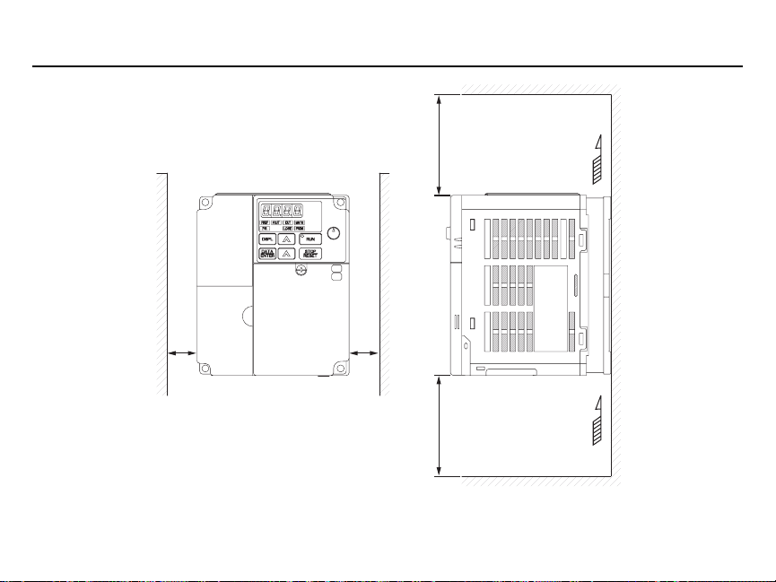
When preparing to mount the Drive, lift it by its base, never by the front cover. For effective cooling, as well as proper maintenance, the Drive must be installed on a flat, non-flammable vertical surface (wall or panel) using recommended mounting
screws. There MUST be a MINIMUM 3.94 in. clearance above and below the Drive to allow air flow over the heat sink fins.
A minimum 1.18 in. clearance is required on each side of the Drive.
16
Page 17
Mounting
PrecautionsSection 3
3.94 in.
(100mm)
1.18 in.
(30mm)
1.18 in.
(30mm)
3.94 in.
(100mm)
Important: To use the CIMR-V7*U25P5, 27P5, 45P5, and 47P5 Drives
as an open chassis, remove top and bottom covers and allow 1.97 in. (50mm)
clearance on each side of the drive.
AIR
AIR
17
Page 18

Wiring Main and Control Circuit Section 4
Main Circuit Input /Output Wiring
• Use 600V vinyl-sheathed wire or equivalent. Wire size and type should be determined by local electrical codes.
• Avoid routing power wiring near equipment sensitive to electrical noise.
• Avoid running input and output wiring in the same conduit.
• NEVER connect AC main power to output terminals T1(U), T2(V), and T3(W).
• NEVER allow wire leads to contact metal surfaces. Short-circuit may result.
• NEVER connect power factor correction capacitors to the Drive output. Consult Yaskawa when connecting noise
filters to the Drive output.
• WIRE SIZING MUST BE SUITABLE FOR CLASS I CIRCUITS.
• When connecting motor to Drive’s output terminals, include a separate ground wire. Attach ground wire solidly to
motor frame and to Drive’s ground terminal .
• When using armored or shielded cable for connection between Drive and motor, solidly connect armor or shield
to motor frame, and to Drive’s ground terminal .
• Motor lead length should NOT EXCEED 164 feet (50 meters), and motor wiring should be run in a separate conduit from the power wiring. If lead length must exceed this distance, reduce carrier frequency (see TM.V7.01,
paragraph 5.8) and consult factory for proper installation procedures.
• Use UL listed closed loop connectors or CSA certified ring connectors sized for the selected wire gauge. Install
connectors using the correct crimp tool recommended by the connector manufacturer.
Control Circuit
All basic control circuit (signal) interconnections are shown in the appropriate diagram:
• Interconnections for external two-wire control in combination with the Digital Operator are shown in Figure 1-5.
• Interconnections for external three-wire control in combination with the Digital Operator are shown in Figure 1-6.
Make wire connections according to Figures 1-5 and 1-6 and Table 1-2; observe the following:
• Signal Leads: Terminals S1-S7 & SC; RP, FS, FR & FC; R+, R-, S+, S-; & AM & AC.
• Control Leads: Terminals P1, P2 & PC; MA, MB & MC.
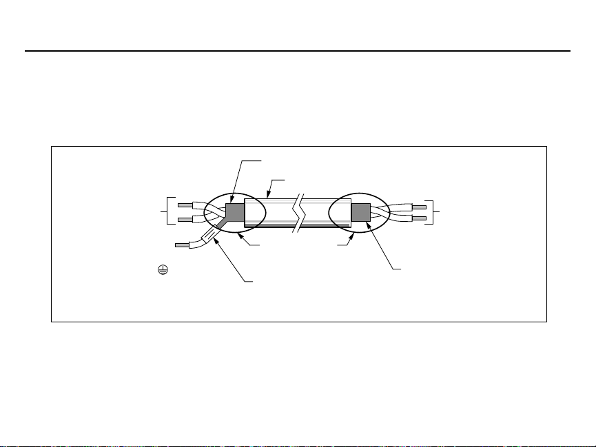
• Use twisted shielded or twisted-pair shielded wire (20-16 AWG [0.5 – 1.25mm2]) for control and signal circuit
leads. The shield sheath MUST be connected at the drive end ONLY (terminal ). The other end should be
dressed neatly and left unconnected (floating). See Figure 1-1.
18
Page 19
Main and Control CircuitSection 4
• Signal leads and feedback leads (PG) must be separated from control leads main circuit leads, and any other
power cables, to prevent erroneous operation caused by electrical noise.
• Lead length should NOT EXCEED 164 feet (50 meters). Wire sizes should be determined considering the voltage drop.
• All AC relays, contactors and solenoids should have RC surge supressors installed across their coils.
• All DC relays, contactors and solenoids should have diodes installed across their coils.
SHIELD SHEATH
OUTER JACKET
Wiring
TO DRIVE
SIGNAL
TERMINALS
TO SHIELD
SHEATH
TERMINAL
(TERM. )
WRAP BOTH ENDS
OF SHEATH WITH
INSULATING TAPE
CRIMP
CONNECTION
Figure 1-1. Shielded Sheath Termination
DO NOT
CONNECT
TO
EXTERNAL
CIRCUIT
19
Page 20

Wiring Grounding Section 4
• The Drive must be solidly grounded using the main circuit ground terminal .
• If Drive is installed in a cabinet with other equipment, ground leads for all equipment should be connected to a
common low-impedance ground point within the cabinet.
• The supply neutral should be connected to the ground point within the cabinet.
• Select appropriate ground wire size from Table 1-1.
• Make all ground wires as short as practical.
• NEVER ground the Drive in common with welding machines, or other high power electrical equipment.
• Where several Drives are used, ground each directly to the ground point (see Figure 1-2). DO NOT FORM A
LOOP WITH THE GROUND LEADS.
• When connecting a motor to the Drive’s output terminals, include a separate ground wire. Attach ground wire
solidly to motor frame and to Drive’s ground terminal .
• When using armored or shielded cable for connection between Drive and motor, solidly connect armor or shield
to motor frame, and to the Drive’s ground terminal .
CORRECT CORRECT NOT
ACCEPTABLE
Figure 1-2. Correct Ground Connection
20
Page 21

Wire and Terminal Screw SizesSection 4
Wiring
230V 3-phase Input
Model
CIMR- lb • in size size Type
V7* MV (N • m) mm
20P1 A001 M3.5
20P2 A002 M3.5
20P4 A003
20P7 A005
21P5 A008 M4
22P2 A011 M4
23P7 A017 M4
25P5 A025 M5
27P5 A033 M5
Table 1.1 Wire and Terminal Screw Sizes
Terminal Symbol Screw Torque Applicable Recommended
R/L1, S/L2, T/L3
B1, B2 (0.8 to 1.0) 10
U/T1, V/T2, W/T3
-, +1,+2 (0.8 to 1.0) 14 600V
Tightening Wire
2
7.1 to 8.88
(0.8 to 1.0) 14
7.1 to 8.88
(0.8 to 1.0) 14
7.1 to 8.88
M3.5
7.1 to 8.88
M3.5
10.65 to 13.31
(1.2 to 1.5) 10 sheathed
10.65 to 13.31
(1.2 to 1.5) 10 equivalent
10.65 to 13.31
(1.2 to 1.5) 10
22.19
(2.5)
22.19
(2.5)
AWG mm2AWG
18 to
0.75 to 2
0.75 to 2
0.75 to 2
0.75 to 2
2 to 5.5
2 to 5.5
2 to 5.5
5.5 to 8 10 to 8 8 8
5.5 to 8 10 to 8 8 8
18 to
18 to
18 to
14 to
14 to
14 to
214
214
214
214
214
3.5 12
5.5 10
460V 3-phase Input
Model
CIMR- lb • in size size Type
V7* MV (N • m) mm2AWG mm2AWG
40P2 B001 M4
40P4 B002 M4
40P7 B003
41P5 B005
42P2 —
43P7 B009 M4
45P5 B015 M4
47P5 —
Terminal Symbol Screw Torque Applicable Recommended
R/L1, S/L2, T/L3
B1, B2 (1.2 to 1.5) 10 sheathed
U/T1, V/T2, W/T3
-, +1,+2
x 1
Tightening Wire
10.65 to 13.31
(1.2 to 1.5) 10
10.65 to 13.31
(1.2 to 1.5) 10 600V
10.65 to 13.31
M4
10.65 to 13.31
M4
(1.2 to 1.5) 10
10.65 to 13.31
(1.2 to 1.5) 10 3.5 x 1 12 x 1
12.43
(1.4) 10
22.19
M5
(2.5) 10
2 to 5.5
2 to 5.5
2 to 5.5
2 to 5.5
2 to 5.5
3.5 to 5.5
5.5 to 8
14 to
214
14 to
214
14 to
214
14 to
214
14 to 2 14
12 to
5.5 10
12 to
5.5 10
Note: The wire size is set for copper wires at 160°F (75°C)
vinyl-
wire or
vinyl-
wire or
equivalent
21
Page 22

Wiring Terminal Functions and Voltages Section 4
Control Circuit
Model Terminal Symbol Screw
S1 to S7, P1, P2, SC,
to
PC, R+, R-, S+, S-,
FS, FR, FC, AM, AC, RP
MA, MB, MC M3
Common
all models
Tightening Wire
Torque
lb • in (N • m) size
4.44 to 5.33 twisted wire 0.5 to 1.25 20 to 16 0.75 18
(0.5 to 0.6) single 0.5 to 1.25 20 to 16
1.94 to 2.21 twisted wire 0.5 to 0.75 20 to 18
M2
(0.22 to 0.25) single 0.5 to 1.25 20 to 16
Applicable size
2
mm
AW G m m2AW G
Recommended
0.75 18
Type
Shielded
wire or
equivalent
Table 1-2. Terminal Functions and Voltages
Table 1-1. Wire and Terminal Screw Sizes - continued
TERMINAL FUNCTION VOLTAGE / SIGNAL LEVEL
L1 (R) 230V Drive: 200 / 208 / 220 / 230V at 50/60 Hz
L2 (S) Main circuit input power supply 460V Drive: 380 / 400 / 440 / 460 / 480V
L3 (T) at 50/60 Hz
T1 (U)
T2 (V) Main circuit output
T3 (W)
B1 For connection of braking resistor (option)
B2
+1
DC Reactor terminals
+2
– DC Bus terminals (+1 & –)
Ground terminal (100 ohms or less) – – – –
S1 Multi-Function-Input 1 Factor y setting is " Forward Run/Stop " (1).
S2 Multi-Function-Input 2 Factory setting is " Reverse Run/Stop " (1).
S3 Multi-Function-Input 3 Factory setting is " External Fault (NO contact)
S4 Multi-Function-Input 4 Factory setting is " Fault Reset " (1)
230V Drive: 0 - 200 / 208 / 220 / 2 30V
460V Drive: 0 - 400 / 440 / 460 / 4 80V
(Forward run when closed, stop when open)
(Reverse Run when closed, stop when open)
input " (1)
(table continued on next page)
22
Page 23

Terminal Functions and VoltagesSection 4
Table 1-2. Terminal Functions and Voltages - continued
TERMINAL FUNCTION VOLTAGE / SIGNAL LEVEL
S5 Multi-Function-Input 5 Factory setting is " Multi-step Speed
S6 Multi-Function-Input 6 Factory setting is " Multi-step Speed
S7 Multi-Function-Input 7 Factory setting is " Jog Reference" (1)
SC Sequence common for terminals S1-S7. Common terminal for sequence inputs
FS Frequency reference power supply +12 VDC
FR Frequency reference input 0 to +10V/100% (20K ohms) or 4-20 mA (250 Ω
RP Frequency reference –Pulse Train input 30 KHz maximum pulse input
FC Frequency reference input common 0 V
MA Multi-function contact output – NO contact Factory Contact capacity:
MB Multi-function contact output – NC contact Setting 250 Vac at 1A or below
MC Multi-function contact output – Common is " Fault " 30 Vdc at 1A or below
AM Multi-function analog monitor (+) Factory setting is
AC Analog monitor common 0 V
P1 Multi-Function Open Factory setting is
Collector Output 1 " Drive Running "
P2 Multi-Function Open Factory setting is
Collector Output 2 " Speed Agree "
PC Multi-Function Open 0V
Collector Output common
R+ Receive input (+) MODBUS
R– Receive input (–) communication RS-485/422 MODBUS protocol,
S+ Send output (+) RS-485 or RS-422. 19.2 kps max.
S– Send output (–)
NOTES:
(1)
These inputs have factory settings based on 2-wire reset. For 3-wire reset definitions, see Figure 1-6.
" Output frequency "
0-10V = 0-100%
Reference 1 " (1)
Reference 2 " (1)
Monitor output: 0 to +10V; 2 mA maximum.
Photocoupler output:
48 VDC; 50 mA or less.
Wiring
)
23
Page 24

Peripheral Devices Section 5
The following peripheral devices may be required to be mounted between the AC main circuit power supply and the Drive
input terminals L1 (R), L2 (S) and L3 (T).
CAUTION
Never connect a general LC/RC noise filter to the Drive output circuit.
Never connect a phase-advancing capacitor to the input/output sides or a surge
suppressor to the output side of the Drive.
When a magnetic contactor is installed between the Drive and the motor, never turn it
on or off during operation.
Note: For more details on peripheral devices, contact your manufacturer.
Recommended Branch Short Circuit Protection Peripheral Devices
All models have UL evaluated motor overload protection built in. Motor overload protection is also provided in accordance with
the NEC and CEC. Additional branch circuit overload protection is not required.
230V 3-Phase
Model CIMR-V7* 20P1 20P2 20P4 20P7 21P5 22P2 23P7 25P5 27P5
Capacity (kVA) 0.3 0.6 1.1 1.9 3.0 4.2 6.7 9.5 13.0
Rated output current (A) 0.8 1.6 3.0 5.0 8.0 11.0 17.5 25.0 33.0
Rated input current (A) 1.1 1.8 3.9 6.4 11.0 15.1 24.0 33.0 39.6
Max. Time Delay Fuse Rating (A)
Max. Non-Time Delay Fuse Rating (A)
Max. MCCB Rating (A) 15 15 15 15 2030 405060
24
MV A001 A002 A003 A005 A008 A011 A017 A025 A033
(1)
1.8 3.2 6.25 10 17.5 20 25 45 60
(2)
3 5 10 20 30 45 45 70 80
Page 25

Peripheral
q
DevicesSection 5
460V 3-Phase
Model CIMR-V7* 40P2 40P4 40P7 41P5 42P2 43P7 45P5 47P5
Capacity (kVA) 0.9 1.4 2.6 3.7 4.2 7.0 11.0 14.0
Rated output current (A) 1.2 1.8 3.4 4.8 5.5 9.2 14.8 18/21
Rated input current (A) 1.6 2.4 4.7 7.0 8.1 12.0 19.6 23.8 / 27.8
Max. Time Delay Fuse Rating (A)
Max. Non-Time Delay Fuse Rating (A)
Max. MCCB Rating (A) 15 15 15 15 20 20 30 40
Notes:
(1)
Apply UL designated Class RK5 fuses.
(2)
Apply UL designated Class CC or T non-time delay fuses.
(3)
Model 47P5 rated 21A is only applicable to the NEMA type 4X/12 version.
Input fuse sizes are determined by NEC guidelines, and should not exceed the ratings shown in the table.
Fuse Ratings are based upon 250V fuses for 230V Drives, and 600V for 460V Drives
Fuse Manufacturer’s Designators: Class CC: KTK, FNQ or equivalent
MV B001 B002 B003 B005 --- B009 B015 B018
(1)
2.8 4 8 12 15 20 35 45
(2)
5 7 12 20 25 35 60 70
Class RK5: FRN, FRS or equivalent
Class T: JJS, JJN or e
uivalent
(3)
Magnetic Contactor
Mount a surge protector on the coil. When using a magnetic contactor to start and stop the Drive, do not exceed one start per
hour.
Ground Fault Interrupter
Select a ground fault interrupter not affected by high frequencies. To prevent malfunctions, the current should be 200mA or
more and the operating time 0.1 second or more.
AC and DC Reactor
Install a reactor to connect to a power supply transformer of large capacity (600 kVA or more) or to improve the power factor
on the power supply side.
Noise Filter
Use a noise filter exclusively for the Drive if radio noise generated from the Drive causes other control devices to malfunction.
25
Page 26

Peripheral
Devices Section 5
Auxiliary Input and Output Power Option Devices
A disconnect device (circuit breaker, contactor, disconnect switch, etc.) should NOT be used as a means of starting and stopping the Drive or motor.
A disconnect device can be installed for emergency stop purposes, but when that disconnect device is opened, there may be
loss of electrical braking.
Figure 1-3 is a factory guideline for proper wiring practices and relative locations within the electrical path from the line to the
load. It does not imply what devices are needed for a particular application, nor does it show what devices were shipped with
a particular order. Therefore, disregard those items in the diagram which are not being used in your installation. However, it is
recommended that an input or DC reactor be used with all Drive ratings when wired to a source of 600 kVA or greater. Mount
all optional power devices close to the Drive, and keep electrical connections as short as possible.
Note: DO NOT run input and output wiring in the same conduit.
26
Page 27

CUSTOMER’S
3fl A.C. LINE
POWER
SUPPLY
NOTES
1. Connect Drive ground terminal or panel to
earth ground. Always use low impedance
paths and connections.
2. Mount input and output RFI filters
as close to the Drive as possible (on the
same panel, if possible). Filters should have
a solid connection from filter case or ground
terminal to Drive panel or ground terminal
(conduit with good bare metal to bare metal
connections may serve as the path). If
multiple input or output RFI filters are used,
they must be wired in parallel.
3. Shield conductors with metallic conduit.
4. Connect output conduit in a manner that
allows it to act as an unbroken shield from the
Drive panel to the motor casing.
5. RF noise filter (different from RFI filter) part
no. 05P00325-0023 is a delta wye capacitor
network which is wired in parallel with the
Drive input terminals. On the smaller Drives
with die cast chassis, it must be mounted
externally. On the larger Drives with sheet
metal chassis, it may be mounted inside the
area where the input power wiring enters the
Drive. On units equipped with bypass, it may
be wired to the primary side of the circuit
breaker and mounted to the bypass panel or
sidewall.
6. Connection points:
Drive w/o Bypass Drive w/ Bypass
L1, L2, L3
Input
Output
T1, T2, T3
physically
Ckt BrkrL1,L2,L3
Unwired side of
Overload relay
L3
L2
L1
ISOLATION
TRANSFORMER
H3
H2
H1
X3
X2
X1
RF NOISE
FILTER
EARTH GROUND
SEE NOTE 2
EARTH GROUND
SEE NOTE 1
RFI FILTER
C1(L3)
B1(L2)
A1(L1)
INPUT
L
L
O
I
A
N
D
E
(G)
SEE NOTE 5
OUTPUT
RFI FILTER
OUTPUT
REACTOR
A.C. MOTOR
(L3)C2
(L2)B2
(L1)A2
EARTH GROUND
SEE NOTE 2
INPUT
AC DRIVE
SEE NOTE 6
INPUT
REACTOR
C1
B1
A1
L3L2L1
OUTPUT
123
IN
OUT
456
SEE NOTE 3
T3T2T1
SEE NOTES 3, 4
SEE NOTES 3, 4
C1B1A1
C2B2A2
SEE NOTES 3, 4
T3T2T1
Peripheral
DevicesSection 5
C2
B2
A2
L31L21L11
DC
REACTOR
+ 1
+ 2
TO CASE
EARTH
GROUND
SEE NOTE 2
Figure 1-3. Customer Connection Diagram For Isolation Transformers, Input Reactors, Input RFI Filters,
DC Reactors, Output Reactors and Output RFI Filters
27
Page 28

Conformance to European EMC Directive Section 6
In order to conform to EMC standards, the following methods are required for line filter application, cable shielding and Drive
installation.
The line filter and Drive must be mounted on the same metal plate. The filter should be mounted as close to the Drive as
practical. The cable must be kept as short as possible and the metal plate should be securely grounded. The ground of the
line filter and the Drive must be bonded to the metal plate with as much bare-metal contact as possible.
For main circuit input cables, a screened cable is recommended within the panel and is also suggested for external connections. The screen of the cable should be connected to a solid ground. For the motor cables, a screened cable (max. 20 m)
must be used and the screen of the motor cable should be connected to ground at both ends by a short connection, again
using as much bare-metal contact as practical.
Table 1-4 and Figure 1-4 show the line filter list for EMC standards and the installation/wiring of the Drive and line filter. For a
more detailed explanation, refer to document “Installation Guidelines for EMC Directive Using AC Drive Products.”
Table 1-4. Line Filters for EMC Standards
Model
CIMR- Part Number Rated Weight Dimensions in in.(mm)
V7* MV FIL00 Current (A) lbs. (kg) H x W x D
20P1 A001
20P2 A002
20P4 A003
20P7 A005
21P5 A008
22P2 A011
23P7 A017 1085 26 2.4 (1.1) 6.9 x 5.7 x 2.0 (174 x 144 x 50) 6.3 x 4.7 (161 x 120) M5
25P5 A025
27P5 A033
40P2 B001
40P4 B002
40P7 B003
41P5 B005
42P2 —
43P7 B009 1088 15 2.4 (1.1) 6.9 x 5.7 x 2.0 (174 x 144 x 50) 6.3 x 4.7 (161 x 120) M5
45P5 B015
47P5 —
28
1083 10 1.8 (0.8) 7.6 x 3.2 x 2.0 (194 x 82 x 50) 7.1 x 2.4 (181 x 62) M5
1084 16 2.2 (1.0) 6.7 x 4.4 x 2.0 (169 x 111 x 50) 6.1 x 3.6 (156 x 91) M5
1100 50 5.1 (2.3) 12.0 x 7.2 x 2.2 (304 x 184 x 56) 11.3 x 5.9 (288 x 150) M6
1086 5 2.2 (1.0) 6.7 x 4.4 x 1.8 (169 x 111 x 45) 6.1 x 3.6 (156 x 91) M5
1087 10 2.2 (1.0) 6.7 x 4.4 x 1.8 (169 x 111 x 45) 6.1 x 3.6 (156 x 91) M5
1101 30 5.1 (2.3) 12.0 x 7.2 x 2.2 (304 x 184 x 56) 11.3 x 5.9 (288 x 150) M6
(1)
D is the distance the filter will extend outward from the surface of the metal plate.
Line Filter
Mounting Dim. in in. (mm) Screw
(1)
H1 x W1 Size
Page 29

European EMC DirectiveSection 6
Conformance to
Cable Length
max. 40cm
L2 PEL1 L3
MAINS
FILTER
LOAD
Ground Bands (remove any paint)
DRIVE
V7
L2L1 L3L1 L3L2
4-d
H
H1
Metal Plate
Motor Cable
max. 20m
W1
D
W
Ground Bands (remove any paint)
IM
3~
Figure 1-4. Installation of Line Filter and V7N Drive
29
Page 30

Interconnection Precautions and Diagrams Section 7
Notes for Figure 1-5 (2-Wire Control) and Figure 1-6 (3-Wire Control)
, – Indicates components not supplied.
– Main circuit terminal.
– Indicates control circuit terminal.
( ) – Indicates alternate terminal marking, i.e., (R) and L1.
L – Function labels shown for these terminals are determined by factory settings of
through
n056
. (see TM.V7N.01)
G – Function labels shown for these terminals are determined by factory settings of
(see TM.V7N.01)
1. Insulated twisted shielded wire is required.
2-conductor #18 GA. (Belden #8760 or equivalent).
3-conductor #18 GA. (Belden #8770 of equivalent).
Connect shield ONLY AT the Drive END (ground terminal ). Stub and isolate other end.
2. +12V voltage output current capacity of control terminal FS is 20mA max.
3. The Drive’s Electronic Thermal Overload function (n036, n037) meets standards set by UL and CUL for motor
thermal overload protection. If local code requires a separate mechanical overload protection, an overload relay
should be installed, interlocked with the Drive as shown. It should be the manual reset type to prevent automatic
restart following a motor fault and subsequent contact reclosure after cool down.
4. Customer to connect terminal to earth ground.
5. If the Digital Operator is used, remote operators, which duplicate functions of its command keys may not be
required. See Figure 4-1.
6. For installation of Braking Resistor or Braking Resistor unit, refer to Appendix 6, “Dynamic Braking Option.”
30
n050
n057
through
n059
.
Page 31

Interconnection Precautions
CAUTION
WARNING
and DiagramsSection 7
7. An optional DC reactor may be added for harmonic attenuation, if needed. See separate instruction sheet for wiring.
8. If application does not allow reverse operation, parameter n006, Reverse Run Prohibit Selection, should be set to
“ 1 ” (Reverse Run Disabled), and the Reverse Run/Stop input can be eliminated.
9. Input fuses are required for proper branch circuit short circuit protection for all NEMA Type 4 drives. Failure
to use recommended fuses (see appendix 4) may result in damage to the drive and/or personal injury.
The Drive leaves the factory with parameters initialized for 2-Wire control (when using external Run/Stop
signals). Before using the initialization function of constant n001, know your control wiring configuration:
10 = Factory 2-Wire Control Initialization (Maintained RUN Contact)
11 = Factory 3-Wire Control Initialization (Momentary START/STOP Contact)
Entering either Initialization code resets all parameters to factory settings, and automatically returns parameter
n001 setting to “ 1 ”. If the Drive is connected for 3-Wire control and this parameter is set to “ 10 ” (2-Wire
Control Initialization), the motor may run in reverse direction WITHOUT A RUN COMMAND APPLIED.
Equipment damage or personal injury may result.
Parameter n012 must be set to proper motor voltage.
Always ground the Drive using the ground terminal provided.
Never connect main circuit output terminals T1 (U), T2 (V) & T3 (W) to AC main circuit power supply.
When programmed for auto-restart ( n082 = “ 1 ” thru “ 10 ”), the motor may restart unexpectedly — personal
injury may result.
For Enclosed wall-mounted type (NEMA type 1)
When mounting units in an enclosure, remove the top, bottom and terminal covers. Install a cooling fan or some
other means to maintain the air entering the enclosure below 113°F (45°C).
31
Page 32

Interconnection Diagram 2-Wire Control Section 7
S3
S4
Figure 1-5. Standard Connections (2-Wire Control)
32
(Parameter n001 set to “10”)
Page 33

Interconnection Diagram
CAUTION
2-Wire ControlSection 7
• After wiring is complete, verify that all wiring is correctly installed, excess screws and wire clippings are removed from inside of unit, screws are securely tightened, and exposed wire does not
contact other wiring or terminals.
• The Drive leaves the factory with all parameters set for 2-wire external control/ reference control.
To use the Drive in a 3-wire application, Drive parameters n001, n003 and n004 must be reprogrammed and Figure 1-6 used for all external connections.
• If a FWD or REV run command is given from the control circuit terminal when the operation
method selection function ( n003 ) is set to “ 1 ” and the “LO/RE” selection is set to “RE”, the
motor will start automatically as soon as power is applied to the main circuit.
33
Page 34

Interconnection Diagram 3-Wire Control Section 7
Figure 1-6. Standard Connections (3-Wire Control)
34
(Parameter n001 set to “11”)
Page 35

Interconnection Diagram
CAUTION
3-Wire ControlSection 7
• After wiring is complete, verify that all wiring is correctly installed, excess screws and wire clippings are removed from inside of unit, screws are securely tightened, and exposed wire does not
contact other wiring or terminals.
• The Drive leaves the factory with all parameters set for 2-wire external control/ reference control.
To use the Drive in a 3-wire application, Drive parameters n001, n003 and n004 must be reprogrammed and Figure 1-6 used for all external connections.
• If a FWD or REV run command is given from the control circuit terminal when the operation
method selection function ( n003 ) is set to “ 1 ” and the “LO/RE” selection is set to “RE”, the
motor will start automatically as soon as power is applied to the main circuit.
35
Page 36

Drive Parameter Listing (n001-n004) Section 8
The Drive control circuits use various parameters to select functions and characteristics of the Drive. Changing of parameter
settings must be done in the Program mode, or by use of the Function LEDs, if available (see TM.V7.01, Section 4).
The following table lists all parameters in numerical order. For each parameter, reference paragraph(s) in TM.V7.01, Section
5 are listed (if applicable) where the features of the Drive affected by that parameter are described.
V7 Parameters
PARA- SETTING RANGE SETTING FACTORY USER PARA.
METER NAME (AND UNITS) INCREMENT SETTING SETTING REF.
n001 Parameter Selection / 4: n001 - n179 can be read and set
Initialization 5: n001 - n179 can be read and set 1 1 5.21
n002 Control Method Selection
n003 Operation Method Selection 1: Terminal 1 1 5.13
n004 Reference Selection
36
0: n001 can be read and set;
n002 - n179 read only
1: n001 - n039 can be read and set
2: n001 - n079 can be read and set
3: n001 - n119 can be read and set
Run command accepted during Program mode
6: Clear Fault History Only
7: Not Used
8: 2-wire Initialization (Japan Spec.)
9: 3-wire Initialization (Japan Spec.)
10: 2 wire initialization (USA Spec)
11: 3 wire initialization (USA Spec.)
0: V/f Control
1: Open Loop Vector
0: Digital Operator
2: Serial Communication (Modbus)
3: Option Card
0: Digital Operator Pot
1: Digital Operator
2: Voltage Reference (0 to 10V)
3: Current Reference (4 to 20 mA)
4: Current Reference (0 to 20 mA) 5.11,
5: Pulse Train Reference 1 2 5.13
6: Serial Communications (Modbus)
7: Multi-Function Analog Input (0 to 10V)
8: Multi-Function Analog Input (4 to 20 mA)
9: Option Card
10 2.2
Page 37

Drive Parameter Listing
V7 Parameters - Continued
PARA- SETTING RANGE SETTING FACTORY USER PARA.
METER NAME (AND UNITS) INCREMENT SETTING SETTING REF.
n005 Stop Method
n006 Reverse Prohibit
n007 STOP Key Function
Reference Selection -
n008
Digital Operator
Frequency Reference Setting new value
n009
Method From Digital Operator 1: ENTER key does not have to be pressed
Operation Selection 0: Disabled (operation continues)
n010 When Digital Operator is 1: Enabled (motor coasts to a stop and fault 1 0 5.15
Disconnected is displayed)
n011 Frequency - Max. 50.0 to 400.0 0.1 (Hz) 60.0
Voltage - Max.
n012
Frequency - Max.
n013
Voltage Point
n014 Frequency - Midpoint 0.1 to 399.9 0.1 (Hz) (Note 2) 5.27
Voltage - Midpoint
n015
n016 Frequency - Min. 0.1 to 10.0 0.1 (Hz) (Note 2)
Voltage - Min.
n017
0: Ramp to stop
1: Coast to stop
0: Reverse Run enabled
1: Reverse Run disabled
0: STOP key is effective regardless of
programming of n003
1: STOP key is effective only when sequence
command (per n003) is from Digital Operator
0: Frequency Reference from digital
operator pot 1 0 5.13
1: Frequency Reference from n024
0: ENTER key must be pressed to write-in
to write-in new value
0.1 to 255.0 (230V drive)
0.2 to 510.0 (460V drive) 460.0
0.2 to 400.0 0.1 (Hz) 60.0
0.1 to 255.0 (230V drive)
0.2 to 510.0 (460V drive)
0.1 to 50.0 (230V drive)
0.2 to 100.0 (460V drive)
10 5.24
10
10 5.13
10 5.13
0.1 (V)
0.1 (V) (Note 2)
0.1 (V) (Note 2)
230.0
(n005-n017)Section 8
37
Page 38

Drive Parameter Listing (n018-n035) Section 8
Drive Parameters - Continued
PARA- SETTING RANGE SETTING FACTORY USER PARA.
METER NAME (AND UNITS) INCREMENT SETTING SETTING REF.
Accel/Decel Time 0: 0.1
n018
Setting Unit 1: 0.01
n019 Acceleration Time 1 (Note 4) 0.00 to 600.0
n020 Deceleration Time 1 (Note 4) or or
n021 Acceleration Time 2 (Note 4) 0.0 to 6000 0.1 (sec)
n022 Deceleration Time 2 (Note 4) (Dependent on n018 setting)
n023 S-curve Selection
n024 Frequency Reference 1 (Note 4) 6.00
n025 Frequency Reference 2 (Note 4) 0.00
n026 Frequency Reference 3 (Note 4) 0. 01 (Hz) 0.00
n027 Frequency Reference 4 (Note 4) 0 .00 to 400.00 (< 100 Hz) 0.00
n028 Frequency Reference 5 (Note 4) o r 0.00 5.1 1
n029 Frequency Reference 6 (Note 4) 0.1 (Hz) 0.00
n030 Frequency Reference 7 (Note 4) (>= 100 Hz) 0.00
n031 Frequency Reference 8 (Note 4) 0.00
n032 Jog Frequency Reference (Note 4) 6.0 0 5.12
Frequency Reference Upper
n033
Limit
Frequency Reference Lower
n034
Limit
Digital Operator 1: 0.1%
n035
Display Mode 2 - 39: rpm
0: No S-cur ve
1: 0.2 second
2: 0.5 second
3: 1.0 second
0. to 110
0. to 110
0: 0.01 Hz (less than 100 Hz) / 0.1 Hz
40 - 3999: custom
38
0
1 (sec) .2
0.01 sec
1(%) 100
1(%) 0
10.0
10
1 0 5.30
5.2
5.3
5.9
Page 39

Drive Parameter Listing
Drive Parameters - Continued
PARA- SETTING RANGE SETTING FACTORY USER PARA.
METER NAME (AND UNITS) INCREMENT SETTING SETTING REF.
n036 Motor Rated Current (Up to 150% of drive rated current) 0.1 (A) (Note 1) 5.25
Electronic Thermal Overload
n037
Protection (for OL1 fault)
Electronic Thermal Overload
n038
Protection Time Constant
Cooling Fan Operation (continues operation for 1 minute after
n039
Selection drive is stopped)
n040 Motor Rotation
Acceleration Time 3
n041
(Note 4)
Deceleration Time 3
n042
(Note 4)
Acceleration Time 4
n043
(Note 4)
Deceleration Time 4
n044
(Note 4)
n050 Multi-function Input [can only be set in n052] 11
Selection 1 (Terminal S1) 1: Forward run (2 wire control) (1)
Multi-function Input
n051
Selection 2 (Terminal S2)
Multi-function Input
n052
Selection 3 (Terminal S3)
0.1 to 49.5
0: Shor t term rating
1: Standard rating 01
2: Disabled 5.25
1 to 60
0: Operates only when drive is running
1: Operates with power applied to drive
0: Rotate C.C.W.
1: Rotate C.W. (or opposite direction)
0.00 to 600.00
or
0.0 to 6000.0
(Dependent on n018 setting)
0: Fwd / Rev command (3 wire control)
2: Reverse run (2 wire control)
3: Exter nal Fault (N.O.)
4: Exter nal Fault (N.C.)
5: Fault Reset
6: Multi-step speed ref. cmd. A
7: Multi-step speed ref. cmd. B
8: Multi-step speed ref. cmd. C
1 (min) 8
10
10
0.01 (sec)
or 5.2
10.0
0.1 (sec)
1 2 5.18
(2)
13
(0)
(n036-n052)Section 8
39
Page 40

Drive Parameter Listing (n053-n058) Section 8
Drive Parameters - Continued
PARA- SETTING RANGE SETTING FACTORY USER PARA.
METER NAME (AND UNITS) INCREMENT SETTING SETTING REF.
Multi-function Input
n053
Selection 4 (Terminal S4)
Multi-function Input
n054
Selection 5 (Terminal S5)
Multi-function Input
n055
Selection 6 (Terminal S6)
n056 Multi-function Input
Selection 7 (Terminal S7)
Multi-Function Output
n057 Selection 1
(Terminals MA, MB & MC)
Multi-Function Output
n058 Selection 2
(Terminals P1 & PC)
40
9: Multi-step speed ref. cmd. D
10: JOG Selection
11: Accel/Decel time change cmd.
12: External Base Block (N.O.)
13: External Base Block (N.C.)
14: Speed search from max. freq.
15: Speed search from set freq.
16: Accel/Decel hold command
17: Remote/Local selection
18: Serial Communication / control ckt.
selection
19: Fast Stop - Fault (N.O.)
20: Fast Stop - Alarm (N.O.)
21: Fast Stop - Fault (N.C.) 1 10
22: Fast Stop - Alarm (N.C.) (10)
23: PID control off
24: I value reset (PID)
25: I value hold (PID)
26: Over Heat Pre-alarm OH3
27: Accel/Decel Time Select 2
34: Up
0: Fault
1: During running
2: Speed Agree
3: Zero Speed
4: Frequency detection 1
5: Frequency detection 2
6: Overtorque detection (N.O.)
7: Overtorque detection (N.C.)
8: Undertorque Detection (N.O.)
9: Undertorque Detection (N.C.) 1 1
10: Minor Fault
11: During Base Block
12: Local / Remote
13: Ready
15
16
17
10
(5)
(6)
(7)
5.18
5.19
Page 41

Drive Parameter Listing
Drive Parameters - Continued
PARA- SETTING RANGE SETTING FACTORY USER PARA.
METER NAME (AND UNITS) INCREMENT SETTING SETTING REF.
Multi-Function Output
n059 Selection 3
(Terminals P2 & PC)
``
Analog Frequency Reference
n060
Gain (term. FR to FC) (Note 4)
Analog Frequency Reference
n061
Bias (term. FR to FC) (Note 4)
Analog frequency reference
n062
filter time constant 0.00 to 2.00 0.01 (sec) 0.10
(term. FR to FC) (Note 4)
Frequency Reference Loss 0: No Detection
n064
Detection 1: Continue to run at 80% of max. frequency
Monitor Output 0: Analog monitor output
n065
Selection 1: Pulse monitor output
Multi-function Analog Output (10V = 400 VDC [800 VDC])
n066
(Terminals AM & AC) 3: Motor Torque 1 0 5.17
n067 Analog Monitor Gain (Note 4) 0.00 to 2.00 0.01 1.00
Analog Frequency Reference
n068
Gain (CN2, Voltage Ref Input)
Analog Frequency Reference
n069
Bias (CN2, Voltage Ref Input)
14: During auto restart
15: During undervoltage
16: During reverse run
17: During speed search 1 2
18: Serial Comm. Controlled
19: PID feedback loss
20: Frequency Reference Loss Detect (N.O.)
21: Overheat Pre-alarm OH3 (N.O.)
0 to 255 1 (%) 100
-100 to 100 1 (%) 0
1 0 5.33
1 0 5.17
0: Output frequency (10V = 100% Fmax)
1: Output Current (10V = 100% drive
rated current)
2: DC Bus Voltage
(10V = Motor rated torque)
4: Output Power
(10V = Drive Capacity kW)
5: Output Voltage 10V = n012 (voltage max)
6: Frequency Reference
-255 to 255 1% 100
-100 to 100 1% 0
5.32
(n059-n069)Section 8
5.8
41
Page 42

Drive Parameter Listing (n070-n079) Section 8
Drive Parameters - Continued
PARA- SETTING RANGE SETTING FACTORY USER PARA.
METER NAME (AND UNITS) INCREMENT SETTING SETTING REF.
Analog Frequency Reference
Filter Time Constant 0.00 to 2.00 0.01 s 0.10
n070
(CN2, Voltage Ref Input)
Analog Frequency Reference
n071
Gain (CN2, Current Ref Input)
Analog Frequency Reference
n072
Bias (CN2, Current Ref Input)
Analog Frequency Reference
Filter Time Constant 0.00 to 2.00 0.01 s 0.10
n073
(CN2, Current Ref Input)
Pulse Train Frequency
n074
Reference Gain
Pulse Train Frequency
n075
Reference Bias
Pulse Train Frequency Ref-
n076
erence Filter Time Constant
n077 Multi-Function Analog
Input Selection
Multi-Function Analog Input 0: 0 - 10V
n078
Signal Selection 1: 4 - 20 mA
Multi-Function Analog Input
n079
Bias Setting
42
-255 to 255 1% 100
-100 to 100 1% 0
-255 to 255 1% 100
-100 to 100 1% 0 5.11
0.00 to 2.00 0.01 s 0.10
0: Multi-Function analog input disabled
1: Aux. Frequency reference
2: Frequency gain 01
3: Frequency bias
4: Voltage bias
10
0 to 50 1% 10
5.32
5.32
Page 43

Drive Parameter Listing
Drive Parameters - Continued
PARA- SETTING RANGE SETTING FACTORY USER PARA.
METER NAME (AND UNITS) INCREMENT SETTING SETTING REF.
n080 Carrier Frequency
Momentary Power Loss recovery within 2 sec.
n081
Ride-through Method 2: Continuous operation after power 1 0 5.16
Number of auto restarts
n082
attempts
n083 Prohibit Frequency 1 0.00 to 400.0
n084 Prohibit Frequency 2 0.00 to 400.0
n085 Prohibit Frequency 3 0.00 to 400.0
n086 Prohibit Frequency Deadband 0.00 to 25.50 0.01 (Hz) 0.00
n089 DC Injection Current 0 to 100 1 (%) 50
n090 DC Injection Time at stop 0.0 to 25.5 0.1 (sec) 0.0 5.7
n091 DC Injection Time at start 0.0 to 25.5 0.1 (sec) 0.0
Stall Prevention During 0: Enabled
n092
Deceleration 1: Disabled
Stall Prevention During
n093
Acceleration
Stall Prevention Level During
n094
Running
n095 Frequency Detection Level 0.00 to 400.0
1 to 4 (x 2.5 kHz)
7 to 9 (synchronous)
0: Not Provided
1: Continuous operation after power
recovery within control logic time
(no fault output)
0 to 10 1 0 5.4
30 to 200 1 (%) 170 5.23
30 to 200 1 (%) 160
13 5.5
0.01 (Hz)
or 0.1 (Hz)
0.01 (Hz)
or 0.1 (Hz)
0.01 (Hz)
or 0.1 (Hz)
0.01 (Hz)
0.00
0.00 5.6
0.00
10
0.00 5.19
(n080-n095)Section 8
43
Page 44

Drive Parameter Listing (n096-n109) Section 8
Drive Parameters - Continued
PARA- SETTING RANGE SETTING FACTORY USER PARA.
METER NAME (AND UNITS) INCREMENT SETTING SETTING REF.
n096 Overtorque Detection (OL3) coast to stop 1 0
Overtorque Detection
n097 Selection (OL3)
(Note 5)
Overtorque Detection
n098
Level (OL3)
Overtorque Detection
n099
Delay Time (OL3)
Up/Down Hold 0: Disabled
n100
Memory 1: Enabled
Speed Search
n101
Deceleration Time
Speed Search Operation
n102
Level
Torque Compensation Gain
n103
(Note 4)
Torque Compensation
n104
Time Constant
Torque Compensation 0.1 (W) or
n105
Iron Loss
n106 Motor Rated Slip (Note 4) 0.0 to 20.0 0.1 (Hz) (Note 1) 2.2, 5.22
Motor Line-to-line
n107
Resistance
Motor Leakage 0.01 (mH)
n108
Inductance (Note 1)
Torque Compensation
n109
Limit (Note 5)
44
0: Detection Disabled
1: Detect only at set frequency;
operation continues
2: Detect only at set frequency;
3: Detect during all frequency conditions;
operation continues
4: Detect during all frequency conditions;
coast to stop 5.20
0: Detected by output torque
1: Detected by output current
30 to 200 1 (%) 160
0.1 to 10.0 0.1 (sec)
0.0 to 10.0 2 5.18
0 to 200% 1 (%) 150 5.18
0.0 to 2.5 0.1 1.0
0.0 to 25.5 (Note 2)
0.0 to 6550
0.000 to 65.50 (Note 1)
0.00 to 655.0
0 to 250 150 5.26
10
0.1
1 0 5.10
0.1 (sec)
0.1 (sec)
(Note 1)
1 (W)
0.001 (ohm)
or 0.1 (mH)
(Note 1)
1 (%)
5.26
Page 45

Drive Parameter Listing
Drive Parameters - Continued
PARA- SETTING RANGE SETTING FACTORY USER PARA.
METER NAME (AND UNITS) INCREMENT SETTING SETTING REF.
n110 Motor No-load Current 0 to 99 1 (%) (Note 1) 2.2
n111 Slip Compensation Gain (Note 4) 0. 0 to 2. 5 (No te 2)
Slip Compensation Primary
n112
Delay Time
Slip Compensation Selection 0: Disabled
n113
During Regeneration 1: Enabled
Stall Prevention Above Base (level is based on setting of n094)
n115
Speed During Run 1: Enabled
Stall Prevention During Run,
n116
Accel/Decel Time Select
n117 Under torque Detection
Select (UL3)
Undertorque Detection Inverter rated current = 100%; if n097 = 0
n118
Level (UL3) (detection by torque); motor rated torque
Undertorque Detection
n119
Time (UL3)
n120 Frequency Reference 9 (Note 4) 0.00
n121 Frequency Reference 10 (Note 4) 0. 01 (Hz ) 0.0 0
n122 Frequency Reference 11 (Note 4) (< 100 Hz) 0.00
n123 Frequency Reference 12 (Note 4) 0.0 0 to 400.00 or 0.00 5.11
n124 Frequency Reference 13 (Note 4) 0.1 (Hz) 0. 00
n125 Frequency Reference 14 (Note 4) (>= 100 Hz) 0.00
n126 Frequency Reference 15 (Note 4) 0.00
n127 Frequency Reference 16 (Note 4) 0.00
0.0 to 25.5 (Note 2)
0: Disabled
(level at Fmax is n094 x 0.4)
0: Follows acc/dec #1 (n019, n020)
or acc/dec #2 (n021, n022)
Note: Multi-Function input selectable 1 0
1: Follows acc/dec #2 (n021, n022)
always
0: Undertorque detection disabled
1: Detected during constant speed running.
Operation continues after detection
2: Detected during constant speed running.
Operation stops during detection
3: Detected during all frequency conditions.
Operation continues
4: Detected during all frequency conditions.
coast to stop
0 to 200%
becomes 100%
0.1 to 10.0 .1
0.1
0.1 (sec)
10
10
10
1(%) 0
0.1 (sec)
(n110-n127)Section 8
5.22
5.23
5.34
45
Page 46

Drive Parameter Listing (n128-n140) Section 8
Drive Parameters - Continued
PARA- SETTING RANGE SETTING FACTORY USER PARA.
METER NAME (AND UNITS) INCREMENT SETTING SETTING REF.
n128 PID Control Selection 5: Inverse PID - D = Feed Forward
n129 PID Feedback Gain (Note 4) 0.00 to 10.00 0.01 1.00
n130 PID Proportional Gain (Note 4) 0.00 to 25.00 0.1 1.0
n131 PID Integral Time (Note 4) 0.00 to 360.00 0.1 s 1.0 5.28
n132 PID Derivative Time (Note 4) 0.00 to 2.50 0.01 0.00
n133 PID Offset Adjustment (Note 4) - 100 to 100 1% 0
n134 Integral Value Limit (Note 4) -100 to 100 1% 100
n135 PID Output Lag Filter Time (Note 4) 0.0 to 10.0
Feedback Loss
n136 1: Enabled - Alarm (operation continues) 1 0
Detection Selection
Feedback Loss
n137
Detection Level
Feedback Loss
n138
Detection Time
Energy Saving Selection
n139
(Energy Saving)
Energy Saving Gain
n140
K2 (Energy Saving)
46
0: PID control disabled
1: D = Feed Forward
2: D = Feedback
3: Reference + PID (D = Feed Forward)
4: Reference + PID (D = Feedback) 1 0
6: Inverse PID - D = Feedback
7: Inverse PID - Reference + PID
(D = Feed Forward)
8: Inverse PID - Reference + PID
(D = Feedback)
0: Disabled
2: Enabled Fault (coast to stop)
0 to 100 1% 0
0.0 to 25.5
0: Energy saving disabled
1: Energy saving enabled
Note: Energy saving becomes enabled by
V/f control mode
0.00 to 6550 0.1 or 1 (Note 1)
0.1 s 1.0
10(Note 2)
5.31
Page 47

Drive Parameter Listing
Drive Parameters - Continued
PARA- SETTING RANGE SETTING FACTORY USER PARA.
METER NAME (AND UNITS) INCREMENT SETTING SETTING REF.
Energy Saving Voltage
n141 Lower Limit at 60 Hz
(Energy Saving)
Energy Saving Voltage
n142 Lower Limit at 6 Hz
(Energy Saving)
Time of Average kW
n143
(Energy Saving) (x 24 ms) (24 ms)
Voltage Limit of Tuning
n144
(Energy Saving)
Step Voltage of Tuning to
n145
100% Output Voltage 0.1 to 10.0 0.1% 0.5
(Energy Saving)
Step Voltage of Tuning to
n146
5% Output Voltage 0.1 to 10.0 0.1% 0.2
(Energy Saving)
n149 Pulse Train Input Scaling 100 to 3300 1 (x 10 Hz)
Pulse Monitor Output 36: 36f output 24, 36, 40,
n150
Frequency Selection Frequency Reference Monitor: 41, 42, 43,
Modbus Time Out
n151
Detection
0 to 120 1% 50
0 to 25 1% 12
1 to 200
1 to 100 1% 0
Output Frequency Monitor:
0: 1440 Hz / Max. output frequency
1: 1f output
6: 6f output
12: 12f output
24: 24f output 0, 1, 6, 12,
40: 1440Hz / Max. output frequency 44, 45
41: Frequency reference * 1
42: Frequency reference * 6
43: Frequency reference * 12
44: Frequency reference * 24
45: Frequency reference * 36
0: Fault - Coast to stop
1: Fault - Ramp to stop (n020)
2: Fault - Ramp to stop (n022) 1 0 5.14
3: Alarm - operation continues
4: Disabled
11
3072
(30,720 Hz)
0 5.17
5.31
5.11
(n141-n151)Section 8
47
Page 48
Drive Parameter Listing (n152-n163) Section 8
Drive Parameters - Continued
PARA- SETTING RANGE SETTING FACTORY USER PARA.
METER NAME (AND UNITS) INCREMENT SETTING SETTING REF.
Modbus Frequency 1: 0.01 Hz
n152
Reference Unit 2: 30000/100%
n153 Modbus Slave Address 0 to 32 1 0
n154 Modbus Baud Rate
n155 Modbus Parity Selection 1: odd parity 1 2
n156 Modbus Send Waiting Time 10 to 65 1 (msec) 10
n157 Modbus RTS control 1: RTS control disabled 1 0
n158 Motor Code 0 to 70 1 (Note 1)
Energy Saving Voltage
n159
Upper Limit At 60 Hz 0 to 120 1% 120
(Energy Saving)
Energy Saving Voltage
n160
Upper Limit At 6 Hz 0 to 25 1% 16
(Energy Saving) 5.31
Power Supply Detection
n161
Hold Width (Energy Saving)
Power Supply Detection
n162
Filter Time Constant (x 4 ms) (20 ms)
n163 PID Output Gain 0.0 to 25.0 0.1 1.0
48
0: 0.1 Hz
3: 0.1 %
0: 2400 bps
1: 4800 bps 5.14
2: 9600 bps
3: 19200 bps
0: even parity
2: no parity
0: RTS control enabled
(RS-422A 1 to 1 communication)
0 to 100 1% 10
0 to 255
10
12
15
5.28
Page 49

Drive Parameter Listing
Drive Parameters - Continued
PARA- SETTING RANGE SETTING FACTORY USER PARA.
METER NAME (AND UNITS) INCREMENT SETTING SETTING REF.
n164 PID Feedback Selection
Input Phase Loss
n166
Detection Level
Input Phase Loss
n167
Detection Time
Output Phase Loss
n168
Detection Level
Output Phase Loss
n169
Detection Time
n173 DC Injection P Gain 1 to 999 1 (0.001) 83 (0.083)
n174 DC Injection I Time 1 to 250 1 (4ms)
n175 Reduce Carrier
at low speed selection
Digital Operator Parameter Cpy: COPY executes Cpy
n176
Copy Function Selection vFy: VERIFY executes vFy
Digital Operator
n177
Parameter copy
Access Selection
n178 Fault History (Note 3) N/A N/A 6.2
n179 Software Number (Note 3) N/A N/A 4.4
Note 1: Factory setting differs depending on V7 capacity. See Appendix 3-1.
Note 2: Factory setting differs depending on control method selected (n002). See Appendix 3-1.
Note 3: n178 and n179 are display only parameters
Note 4: Parameter can be changed while V7 is operating.
0: Terminal FR (Voltage 0 - 10V)
1: Terminal FR (Current 4 - 20mA)
2: Terminal FR (Current 0 - 20mA)
3: Multi-Function Analog Input
(Voltage 0 - 10V)
4: Multi-Function Analog Input
(Current 4 - 20mA)
5: Pulse input
0 to 100 (%) 1% 0
0 to 255 (sec) 1 sec 0
0 to 100 (%)
0.0 to 2.0 (sec) 0.1 sec 0
0: Disabled
1: Carrier Frequency reduced to 2.5kHz 1 0 5.5
when Fout <= 5Hz & Iout >= 110%
rdy : READY status rdy
rEd: READ executes rEd
vA: Inverter capacity display vA
Sno: Software No. display
0: Read disabled
1: Read allowed
1 0 5.28
1% 0
25
(100ms)
rdy 5.29
Sno
1 0 5.29
(n164-n179)Section 8
49
Page 50

Monitor Displays Section 9
When using the Monitor Function, a variety of information will appear on the Digital Operator display when each of the U-XX
(display only) parameters is selected.
PARAMETER DISPLAY
U - MONITORED ITEM EXAMPLE
01 Frequency reference (Hz) 60.0
02 Output frequency (Hz) 60.0
03 Output current (A) 12.5
04 AC output voltage (V) 230
05 DC Bus voltage (VPN ) 325
06 Input terminal status
07 Output Terminal status IIIIIIII
08 Motor Torque (%) 72
(Open loop vector only)
09 Fault record (last 4 faults)
10 Software number 0024
XXXX
(3)
11 Output Power (KW) 99.9
15 Data reception error
16 PID Feedback (%) 35.0
17 PID Input (%) 100
18 PID Output (%) 75.5
50
IIIIIIII
oC
IIIIIIII
(1)
(2)
(4)
Page 51

Monitor DisplaysSection 9
(1)
Actual display appearance:
Term.S1 input OPEN
Term.S2 input CLOSED
Term.S3 input OPEN
Term.S4 input CLOSED
Term. S6 input CLOSED
Term.S7 input OPEN
Not used
Term.S5 input OPEN
(3)
See TM.V7.01, Section 6 for viewing
of fault log contents.
(4)
Actual display appearance:
CRC error
Data length OK
Not used
Parity error
Over run error
Framing OK
Timeout error
Not used
(2)
Actual display appearance:
MA-MC CLOSED
P1 - PC OPEN
P2 - PC CLOSED
{
Not used
51
Page 52

Drive Dimensions Section 10
Fig. 1
2-d
H2
W W
W
52
0.06
(1.5)
H3H1
H
H4
0.16
(4.0)
0.33
(8.5)
D
Page 53

Drive DimensionsSection 10
V7 Enclosed wall mounted type (NEMA type 1)
Volta ge
3-phase 20P4 A003 1/2 2.68 5.83 4.25 2.20 4.65 0.20 0.24 5.04 0.79 M4 2.20 15.8 12.3 28.1 1
Model Si ze Di mensions in inches (mm) Weight Heat Loss (W)
CIMR- Lbs. Heat-
Class
V7* MV
20P1 A001 1/8 2.68 5.83 2.99 2.20 4.65 0.20 0.24 5.04 0.79 M4 1.55 3.7 9.3 13.0 1
20P2 A002 1/4 2.68 5.83 2.99 2.20 4.65 0.20 0.24 5.04 0.79 M4 1.55 7.7 10.3 18.0 1
230V (68) (148) (76) (56) (118) (5) (6) (128) (20) (0.7)
20P7 A005 3/4 & 1 2.68 5.83 5.04 2.20 4.65 0.20 0.24 5.04 0.79 M4 2.65 28.4 16.7 45.1 1
(1)
When drives include network communications option board, add 1.5" to drive depth.
HP W H DW1H1H2W2H3H4d
(68) (148) (76) (56) (118) (5) (6) (128) (20) (0.7)
(68) (148) (108) (56) (118) (5) (6) (128) (20) (1.0)
(68) (148) (128) (56) (118) (5) (6) (128) (20) (1.2)
(kg) sink Internal Total
Fig.
53
Page 54

Drive Dimensions Section 10
Fig. 2
4-d
H2
W1
W
W
54
0.06
(1.5)
H
H3H1
H4
0.16
(4.0)
0.33
(8.5)
D
Page 55

Drive DimensionsSection 10
V7 Enclosed wall mounted type (NEMA type 1)
Volta ge
3-phase (108) (148) (140) (96) (118) (5) (6) (128) (20) (1.7)
3-phase (108) (148) (140) (96) (118) (5) (6) (128) (20) (1.7)
(1)
Model Si z e Dimensions in inches (mm) Weight Heat Loss (W )
CIMR- Lbs. Heat -
Class
V7* MV
21P5 A008 2 4.25 5.83 5.16 3.78 4.65 0.20 0.24 5.04 0.79 M4 3.53 53.7 19.1 72.8 2
230V 22P2 A011 3 4.25 5.83 5.51 3.78 4.65 0.20 0.24 5.04 0.79 M4 3.75 60.4 34.4 94.8 2
23P7 A017 5 5.51 5.83 5.63 5.04 4.65 0.20 0.24 5.04 0.79 M4 5.30 96.7 52.4 149.1 2
40P2 B001 1/2 4.25 5.83 3.62 3.78 4.65 0.20 0.24 5.04 0.79 M4 2.65 9.4 13.7 23.1 2
40P4 B002 3/4 4.25 5.83 4.43 3.78 4.65 0.20 0.24 5.04 0.79 M4 2.65 15.1 15.0 30.1 2
460V 40P7 B003 1& 2 4.25 5.83 5.51 3.78 4.65 0.20 0.24 5.04 0.79 M4 3.75 30.3 24.6 54.9 2
41P5 B005 3 4.25 5.83 6.14 3.78 4.65 0.20 0.24 5.04 0.79 M4 3.75 45.8 29.9 75.7 2
42P2 — 3 4.25 5.83 6.14 3.78 4.65 0.20 0.24 5.04 0.79 M4 3.75 50.5 32.5 83.0 2
43P7 B009 5 5.51 5.83 5.63 5.04 4.65 0.20 0.24 5.04 0.79 M4 5.30 73.4 44.5 117.9 2
HP W H DW1H1H2W2H3H4d
(108) (148) (131) (96) (118) (5) (6) (128) (20) (1.6)
(140) (148) (143) (128) (118) (5) (6) (128) (20) (2.4)
(108) (148) (92) (96) (118) (5) (6) (128) (20) (1.2)
(108) (148) (110) (96) (118) (5) (6) (128) (20) (1.2)
(108) (148) (156) (96) (118) (5) (6) (128) (20) (1.7)
(108) (148) (156) (96) (118) (5) (6) (128) (20) (1.7)
(140) (148) (143) (128) (118) (5) (6) (128) (20) (2.4)
(kg) sin k Internal Total
When drives include network communications option board, add 1.5" to drive depth.
Fig.
55
Page 56

Drive Dimensions Section 10
Fig. 3
4-d
0.06
(1.5)
H
H1
H2
0.09
(2.20)
W1
W
56
W2
0.33
(8.5)
D
Page 57

Drive DimensionsSection 10
V7 Enclosed wall mounted type (NEMA type 1)
Volta ge
3-phase 27P5 A033 10 7.09 10.24 6.70 6.46 9.61 0.31 0.31 – – M5 11.89 219.2 98.9 318.1 3
3-phase 47P5 – 15
(1)
(2)
(3)
Model Si z e Dimensions in inches (mm) Weight Heat Loss (W )
CIMR- Lbs. Heat -
Class
V7* MV
25P5 A025 7.5 7.09 10.24 6.70 6.46 9.61 0.31 0.31 – – M5 11.45 170.4 79.4 249.8 3
230V (180) (260) (170) (164) (244) (8) (8) (5.2)
45P5 B015 10 7.09 10.24 6.70 6.46 9.61 0.31 0.31 – – M5 10.14 168.8 87.7 256.5 3
460V (180) (260) (170) (164) (244) (8) (8) (4.6)
HP W H DW1H1H2W2H3H4d
(180) (260) (170) (164) (244) (8) (8) (5.4)
(3)
7.09 10.24 6.70 6.46 9.61 0.31 0.31 – – M5 10.58 209.6 99.3 308.9 3
(180) (260) (170) (164) (244) (8) (8) (4.8)
(kg) sink Internal Total
When drives include network communications option board, add 1.5" to drive depth.
230 and 460V drives represented in Figure 3 can be used as “IP00” type enclosures
if the top and bottom covers are removed.
Horsepower rating of 15 only
available as V74X drive.
Fig.
57
Page 58

Drive Dimensions Section 10
Fig. 4
4-d
H1 H
H2
W
W
58
W
D
Page 59

V74X Enclosed wall mounted type (NEMA 4)
Model Size Dimensions in inches (mm) Weight
Volta ge
CIMR- Lbs.
Class
230V (170) (254) (190) (158) (239) (6) (6) (5) (5.90)
3-Phase 22P24 3 6.69 10.0 7.48 6.22 9.41 0.24 0.24 0.20 13.3 4
460V 41P54 3 6.69 10.0 7.48 6.22 9.41 0.24 0.24 0.20 13.3 4
3-Phase (170) (254) (190) (158) (239) (6) (6) (5) (6.00)
HP W H D W1 H1 H 2 W2 d
V7CU
20P24 0.25 6.10 7.56 6.50 5.55 7.01 0.28 0.28 0.20 7.8 4
20P44 0.5 6.10 7.56 6.50 5.55 7.01 0.28 0.28 0.20 8.0 4
20P74 1 6.10 7.56 6.50 5.55 7.01 0.28 0.28 0.20 8.2 4
21P54 2 6.69 10.0 7.48 6.22 9.41 0.24 0.24 0.20 13.0 4
23P74 5 6.69 10.0 7.48 6.22 9.41 0.24 0.24 0.20 13.7 4
25P54 7.5 11.41 15.98 11.34 10.63 14.17 0.91 0.39 0.28 41.5 4
27P54 10 11.41 15.98 11.34 10.63 14.17 0.91 0.39 0.28 41.5 4
40P24 1/2 6.10 7.56 6.50 5.55 7.01 0.28 0.28 0.20 8.4 4
40P44 3/4 6.10 7.56 6.50 5.55 7.01 0.28 0.28 0.20 8.4 4
40P74 1 & 2 6.10 7.56 6.50 5.55 7.01 0.28 0.28 0.20 8.7 4
42P24 3 6.69 10.0 7.48 6.22 9.41 0.24 0.24 0.20 13.3 4
43P74 5 6.69 10.0 7.48 6.22 9.41 0.24 0.24 0.20 13.7 4
45P54 7.5 & 10 11.41 15.74 11.42 10.63 14.17 0.79 0.39 0.28 41.5 4
47P54 15
(155) (192) (165) (141) (178) (7) (7) (5) (3.52)
(155) (192) (165) (141) (178) (7) (7) (5) (3.62)
(155) (192) (165) (141) (178) (7) (7) (5) (3.72)
(170) (254) (190) (158) (239) (6) (6) (5) (6.00)
(170) (254) (190) (158) (239) (6) (6) (5) (6.20)
(290) (406) (288) (270) (360) (23) (10) (7) (18.6)
(290) (406) (288) (270) (360) (23) (10) (7) (18.8)
(155) (192) (165) (141) (178) (7) (7) (5) (3.82)
(155) (192) (165) (141) (178) (7) (7) (5) (3.82)
(155) (192) (165) (141) (178) (7) (7) (5) (3.92)
(170) (254) (190) (158) (239) (6) (6) (5) (6.00)
(170) (254) (190) (158) (239) (6) (6) (5) (6.20)
(290) (400) (290) (270) (360) (20) (10) (7) (18.8)
(1)
11.41 15.74 11.42 10.63 14.17 0.79 0.39 0.28 41.5 4
(290) (400) (290) (270) (360) (20) (10) (7) (18.8)
(kg)
When drives include network communications option board, add 2.0" to drive depth.
(1)
Applicable to the V74X Model only.
Drive DimensionsSection 10
Fig.
59
Page 60

Notes
Page 61

Notes
Page 62

V7 and V74X Drives
YASKAWA ELECTRIC AMERICA, INC.
Drives Division
16555 W. Ryerson Rd., New Berlin, WI 53151, U.S.A.
Phone: (800) YASKAWA (800-927-5292) Fax: (262) 782-3418
Internet: http://www.drives.com
YASKAWA ELECTRIC AMERICA, INC.
Chicago-Corporate Headquarters
2121 Norman Drive South, Waukegan, IL 60085, U.S.A.
Phone: (800) YASKAWA (800-927-5292) Fax: (847) 887-7310
Internet: http://www.yaskawa.com
MOTOMAN INC.
805 Liberty Lane, West Carrollton, OH 45449, U.S.A.
Phone: (937) 847-6200 Fax: (937) 847-6277
Internet: http://www.motoman.com
YASKAWA ELECTRIC CORPORATION
New Pier Takeshiba South Tower, 1-16-1, Kaigan, Minatoku, Tokyo, 105-0022, Japan
Phone: 81-3-5402-4511 Fax: 81-3-5402-4580
Internet: http://www.yaskawa.co.jp
YASKAWA ELETRICO DO BRASIL COMERCIO LTDA.
Avenida Fagundes Filho, 620 Bairro Saude Sao Paolo-SP, Brasil CEP: 04304-000
Phone: 55-11-5071-2552 Fax: 55-11-5581-8795
Internet: http://www.yaskawa.com.br
YASKAWA ELECTRIC EUROPE GmbH
Am Kronberger Hang 2, 65824 Schwalbach, Germany
Phone: 49-6196-569-300 Fax: 49-6196-888-301
MOTOMAN ROBOTICS AB
Box 504 S38525, Torsas, Sweden
Phone: 46-486-48800 Fax: 46-486-41410
MOTOMAN ROBOTEC GmbH
Kammerfeldstrabe 1, 85391 Allershausen, Germany
Phone: 49-8166-900 Fax: 49-8166-9039
YASKAWA ELECTRIC UK LTD.
1 Hunt Hill Orchardton Woods Cumbernauld, G68 9LF, Scotland, United Kingdom
Phone: 44-12-3673-5000 Fax: 44-12-3645-8182
Document Number: IG.V7.01 11/1/06 Rev. 06-11
Data Subject to change without notice. Yaskawa Electric America, Inc.
YASKAWA ELECTRIC KOREA CORPORATION
Paik Nam Bldg. 901 188-3, 1-Ga Euljiro, Joong-Gu, Seoul, Korea
Phone: 82-2-776-7844 Fax: 82-2-753-2639
YASKAWA ELECTRIC (SINGAPORE) PTE. LTD.
Head Office: 151 Lorong Chuan, #04-01, New Tech Park Singapore 556741, Singapore
Phone: 65-282-3003 Fax: 65-289-3003
TAIPEI OFFICE (AND YATEC ENGINEERING CORPORATION)
10F 146 Sung Chiang Road, Taipei, Taiwan
Phone: 886-2-2563-0010 Fax: 886-2-2567-4677
YASKAWA JASON (HK) COMPANY LIMITED
Rm. 2909-10, Hong Kong Plaza, 186-191 Connaught Road West, Hong Kong
Phone: 852-2803-2385 Fax: 852-2547-5773
BEIJING OFFICE
Room No. 301 Office Building of Beijing International Club,
21 Jianguomanwai Avenue, Beijing 100020, China
Phone: 86-10-6532-1850 Fax: 86-10-6532-1851
SHANGHAI OFFICE
27 Hui He Road Shanghai 200437 China
Phone: 86-21-6553-6600 Fax: 86-21-6531-4242
SHANGHAI YASKAWA-TONJI M & E CO., LTD.
27 Hui He Road Shanghai 200437 China
Phone: 86-21-6533-2828 Fax: 86-21-6553-6677
BEIJING YASKAWA BEIKE AUTOMATION ENGINEERING CO., LTD.
30 Xue Yuan Road, Haidian, Beijing 100083 China
Phone: 86-10-6232-9943 Fax: 86-10-6234-5002
SHOUGANG MOTOMAN ROBOT CO., LTD.
7, Yongchang-North Street, Beijing Economic & Technological Development Area,
Beijing 100076 China
Phone: 86-10-6788-0551 Fax: 86-10-6788-2878
YEA, TAICHUNG OFFICE IN TAIWAIN
B1, 6F, No.51, Section 2, Kung-Yi Road, Taichung City, Taiwan, R.O.C.
Phone: 886-4-2320-2227 Fax:886-4-2320-2239
 Loading...