

Page 1

V7 PROFIBUS-DP
Technical Manual
®
Option
Models: CIMR-V7* Document Number TM.V7.12
Page 2

Page 3

Warnings and Cautions
This Section provides warnings and cautions pertinent to this product, that if not heeded, may
result in personal injury, fatality, or equipment damage. Yaskawa is not responsible for
consequences of ignoring these instructions.
WARNING
YASKAWA manufactures component parts that can be used in a wide variety of industrial applications. The selection and application of
YASKAWA products remain the responsibility of the equipment designer or end user. YASKAWA accepts no responsibility for the way its
products are incorporated into the final system design. Under no circumstances should any YASKAWA product be incorporated into any
product or design as the exclusive or sole safety control. Without exception, all controls should be designed to detect faults dynamically
and to fail safely under all circumstances. All products designed to incorporate a component part manufactured by YASKAWA must be
supplied to the end user with appropriate warnings and instructions as to that part’s safe use and operation. Any warnings provided by
YASKAWA must be promptly provided to the end user. YASKAWA offers an express warranty only as to the quality of its products in
conforming to standards and specifications published in the YASKAWA manual. NO OTHER WA RRANTY, EXPRESS OR IMPLIED, IS
OFFERED. YASKAWA assumes no liability for any personal injury, property damage, losses, or claims arising from misapplication of its
products.
WARNING
Read and understand this manual before installing, operating, or servicing this drive. All warnings, cautions, and instructions must be
followed. All activity must be performed by qualified personnel. The drive must be installed according to this manual and local codes.
Do not connect or disconnect wiring while the power is on. Do not remove covers or touch circuit boards while the power is on. Do
not remove or insert the digital operator while power is on.
Before servicing, disconnect all power to the equipment. The internal capacitor remains charged even after the power supply is turned
off. Status indicator LEDs and Digital Operator display will be extinguished when the DC bus voltage is below 50 VDC. To prevent
electric shock, wait at least 5 minutes after all indicators are OFF and measure DC bus voltage and verify that it is at a safe level.
Do not perform a withstand voltage test on any part of the unit. This equipment uses sensitive devices and may be damaged by high
voltage.
The drive is not suitable for circuits capable of delivering more than the specified RMS symmetrical amperes. Install adequate branch
short circuit protection per applicable codes. Refer to the specification. Failure to do so may result in equipment damage and/or
personal injury.
Do not connect unapproved LC or RC interference suppression filters, capacitors, or over voltage protection devices to the output of
the drive. Capacitors may generate peak currents that exceed drive specifications.
To avoid unnecessary fault displays, caused by contactors or output switches placed between drive and motor, auxiliary contacts must
be properly integrated into the control logic circuit.
YASKAWA is not responsible for any modification of the product made by the user, doing so will void the warranty. This product
must not be modified.
Verify that the rated voltage of the drive matches the voltage of the incoming power supply before applying power.
To meet CE directives, proper line filters and proper installation are required.
Some drawings in this manual may be shown with protective covers or shields removed, to describe details. These must be replaced
before operation.
Observe Electrostatic Discharge Procedures when handling the drive and drive components to prevent ESD damage.
The attached equipment may start unexpectedly upon application of power to the drive. Clear all personnel from the drive, motor and
machine area prior to applying power. Secure covers, couplings, shaft keys, machine beds and all safety equipment before energizing
the drive.
Do not attempt to disassemble this unit. There are no user serviceable parts. Disassembling this unit will void any and all
warranties.
i
Page 4

Introduction
This manual explains the specifications and handling of the Yaskawa V7 PROFIBUS-DP Option for the Yaskawa model V7 drive. The V7
PROFIBUS-DP Option connects the drive to a PROFIBUS-DP network and facilitates the exchange of data.
This document pertains to the V7 drive. However, this document is equally applicable to drives identified as GPD 315, GPD 315/V7, GPD
315/V74X, and V74X. Additionally, in this document, the word “inverter”, “ac drive” and “drive” may be used interchangeably.
To ensure proper operation of this product, read and understand this manual. For details on installation and operation of the V7 drive, refer
to the V7 Technical Manual. For details on specific V7 parameters, refer to the V7 MODBUS
and support files are available on the CD that came with the drive, CD.4005, and are available for download at www.drives.com
For information on PROFIBUS-DP contact the PROFIBUS Organization at www.profibus.org.
V7 T echnical Manual document reference TM.V7.01
V7 MODBUS
V7 PROFIBUS-DP Technical Manual document reference TM.V7.12
GPD is a trademark of Yaskawa, Inc.
MODBUS
PROFIBUS
All trademarks are the property of their respective owners.
®
T echnical Manual document reference TM.V7.11
®
is a registered trademark of Schneider Automation, Inc.
®
and PROFIBUS-DP® are registered trademarks of PROFIBUS Nutzerorganisation e.V.
®
T echnical Manual. All technical manuals
.
ii
Page 5

Table of Contents
Chapter 1 Installation...........................................................................1-1
Installation Check Sheet.....................................................................................1-3
Unpack and Inspect............................................................................................1-5
Installation and Wiring........................................................................................1-6
Option LEDs.....................................................................................................1-11
Drive Faults ......................................................................................................1-13
Parameter Settings...........................................................................................1-14
Chapter 2 Network Configuration....................................................... 2-1
Configuration......................................................................................................2-3
GSD File.............................................................................................................2-6
Chapter 3 Network Communications.................................................3-1
16 Word Input/Output Message..........................................................................3-3
6 Word Input/Output Message............................................................................3-7
3 Word I/Os Message.......................................................................................3-10
Parameter Access Error Messages..................................................................3-12
Handshaking..................................................................................................... 3-13
Appendix A Product Specification........................................................ 1
Appendix B Parameter Access.............................................................. 1
Parameter Access Overview .................................................................................3
Read Drive Data Example.....................................................................................5
Read Drive Data Error Example............................................................................6
Write Drive Data Example.....................................................................................7
Write Drive Data Error Example............................................................................8
Appendix C Troubleshooting................................................................. 1
Troubleshooting Check List...................................................................................3
Installation Troubleshoo ting...................................................................................5
Wiring And Cabling................................................................................................8
PROFIBUS-DP Configuration..............................................................................11
V7 PROFIBUS-DP Option Diagnostics................................................................12
iii
Page 6

This page intentionally left blank.
iv
Page 7

Chapter 1 Installation
This chapter describes how to install and setup the V7 PROFIBUS-DP Option
Installation Check Sheet................................................... 1 - 3
Unpack & Inspect .............................................................. 1 - 5
Installation And Wiring...................................................... 1 - 6
Option LEDs...................................................................... 1 - 11
Drive Faults...................................................................... 1 – 13
Parameter Settings.......................................................... 1 - 14
Installation 1-1
Page 8

This page intentionally left blank
Installation 1-2
Page 9

Installation Check Sheet
The following is a quick reference guide to install and configure the V7 PROFIBUS-DP Option. Make a copy of this page and check-off
each item as it is completed. For detailed information please refer to the detailed sections that follow.
1: Unpack the V7 PROFIBUS-DP Option and verify that all components are present and undamaged. Refer to Figure 1.1 –
V7PROFIBUS-DP Option, Table 1.1 – Product Parts List .
2:
3:
4:
Connect power to the drive and verify that the drive functions correctly. This includes running the drive from the operator
keypad. Refer to the V7 Technical Manual for information on connecting and operating the drive.
Remove power from the drive and wait for the charge lamp to be completely extinguished. Wait at least five additional
minutes for the drive to be completely discharged. Measure the DC bus voltage and verify that it is at a safe level.
Install the V7 PROFIBUS-DP Option on the drive.
4.1:
4.2:
4.3:
4.4:
4.5:
5:
6:
Connect the V7 to the PROFIBUS-DP communication network. Refer to Figure 1.4 – V7 PROFIBUS-DP Option
Connections and Table 1.3 - PROFIBUS-DP Cable Connections
Set the node address for the drive. Refer to Figure 1.5 – Setting the V7 PROFIBUS-DP Option Node Address.
Remove the V7 operator keypad and terminal cover.
Remove the plastic protective cover from over the CN2 connector. Refer to Figure 1.2 –Remove CN2 Cover and
Install Option Mounting Bracket.
Install the option mounting bracket provided on to the drive. Refer to Figure 1.2 – Remove CN2 Cover and
Install Option Mounting Bracket.
Connect the ground wire provided to the ground connector on the back of the V7 PROFIBUS-DP Option. Refer to
Table 1.2 – Ground Cables & Drive Models and to Figure 1.3 – Mount the V7 Option.
Mount the V7 PROFIBUS-DP Option onto the drive. Refer to Figure 1.3 – Mount the V7 Option.
7:
8:
9:
10:
11:
12:
13:
If this unit is either the first or the last device on the network, including PLCs and PROFIBUS-DP Masters, and active
termination is not used, set the termination resistor switch to ON. If this device is not the first or last device on the network
or active termination is used, set the termination resistor switch to OFF. Refer to Figure 1.6 – Termination Switch.
Secure the V7 PROFIBUS-DP Option to the drive.
Configure the PROFIBUS network for the drive. Refer to the documentation included with the PROFIBUS configuration
utility supplied with the PROFIBUS-DP Master controller.
Apply power to the drive. And verify that the diagnostic LEDs on the front of the V7 PROFIBUS-DP Option are in their
correct state. Refer to Table 1.4 –Diagnostic LED Status.
Remove power from the drive and wait for the charge lamp to be completely extinguished. Wait at least five additional
minutes for the drive to be completely discharged. Measure the DC bus voltage level to confirm that it is at a safe level.
Reinstall the operator keypad and terminal cover.
Set parameters n003, n004 and n035 to their appropriate values. Refer to Table 1.5 – Option Specific Parameter Settings.
Installation 1-3
Page 10

This page intentionally left blank.
Installation 1-4
Page 11

Unpack and Inspect
Prior to unpacking, check the package label and verify that the product received matches the product ordered. Unpack the option and verify
that the following items are included in the product package and are undamaged.
Locking Screw
Indicator
LEDs
ERR
COMM
PWR
WD
Front
Profibus Cable
Connector
S2 S1
Termination Switch
Mounting Bracket
M3x8 Screw
Figure 1.1 – V7 PROFIBUS-DP Option
CN1 - Modular Plug
RJ45 Female
Node Address
Switches
Ground Wires
E
E
E
6" (150mm)
8.5" (220mm)
12.5" (320mm)
CN3 - Modular Plug
RJ45 Male
CN1
Connector
Back
Ground Wire Connec t i o n
E
E
E
Table 1.1 – Product Parts List
Part Qty.
V7 PROFIBUS-DP Option 1
Mounting Bracket 1
M3×8 Screw 1
6” Ground Wire (150mm) 1
8.5” Ground Wire (220mm) 1
12.5” Ground Wire (320mm) 1
Quick Start Installation Guide 1
Installation 1-5
Page 12

Installation and Wiring
The following describes the installation and configuration of the V7 PROFIBUS-DP Option. For detailed information please refer to the
appropriate sections of this manual or the V7 Technical Manual.
Verify Drive Operation
Connect power to the drive and verify that the drive functions properly. This includes running the drive from the operator
keypad. Refer to the V7 Technical Manual, for information on connecting and operating the drive.
Remove power from the drive and wait for the charge lamp to be com pletely extinguished. Wait at least five additional minutes
for the drive to be completely discharged. Measure DC bus voltage and verify that it is at a safe level.
Remove the operator keypad and terminal cover.
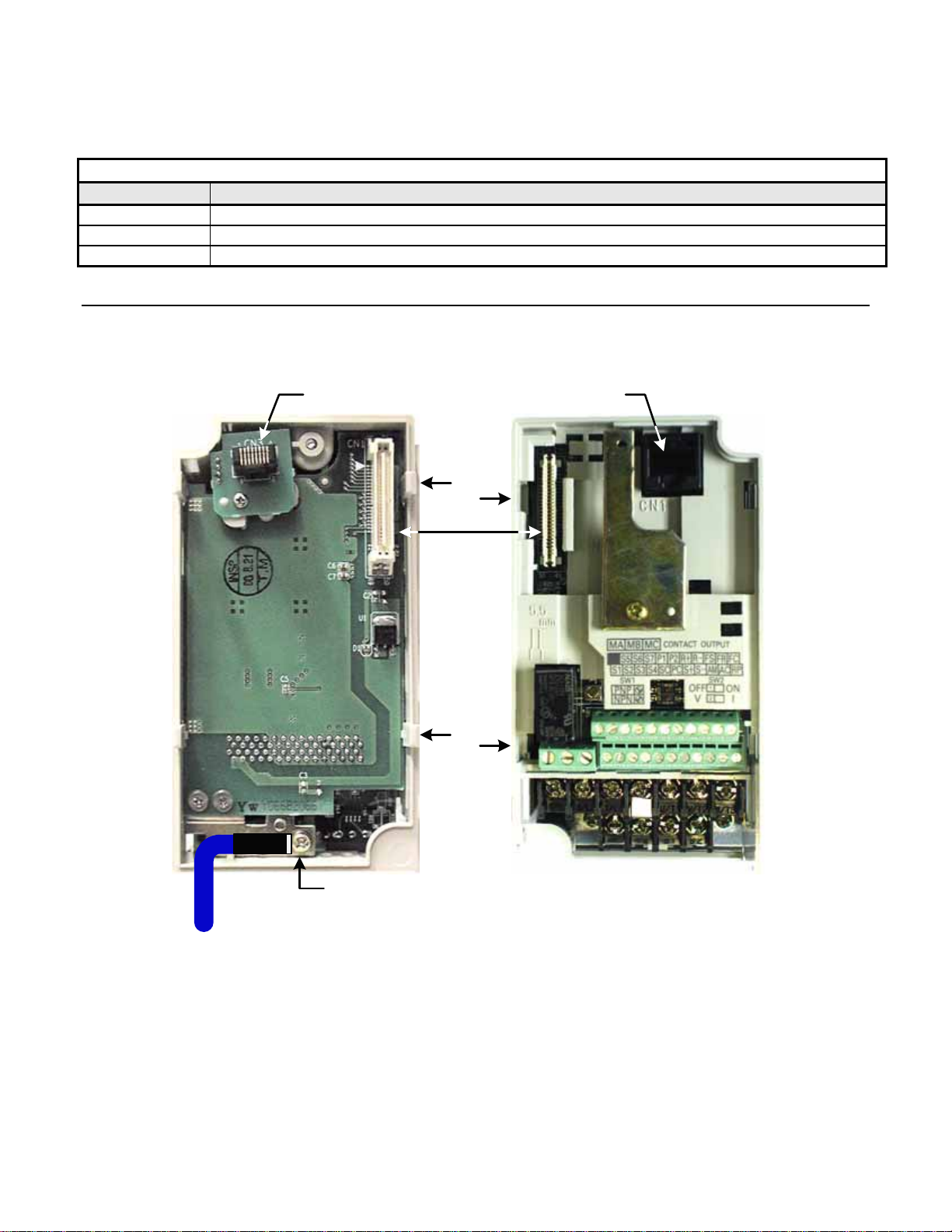
Remove CN2 Protective Cover and Install Mounting Bracket
Remove the plastic protective cover from the CN2 connector on the drive by cutting the three tabs as shown below. Install the option
mounting bracket and secure it to the drive with the M3x8 screw provided.
Remove the CN2
protective cover
by carefully
clipping the
three tabs
CN2 Cover
Option kit mounting
bracket
Align hole in
mounting bracket
with nib on front of
the V7 drive
Secure mounting
bracket to V7 drive
with M3x8 screw
provided
Figure 1.2 – Remove CN2 Cover and Install Option Mounting Bracket
Installation 1-6
Page 13
Connect Ground Wire
Connect the ground wire to the ground connector on the back of the V7 PROFIBUS-DP Option. Select the wire of the appropriate length
based on drive model.
Table 1.2 – Ground Cable & Drive Models
Cable Length Drive Models
6” (150mm) 20P1, 20P2, 40P2
8.5” (220mm) 20P4, 20P7, 21P5, 22P2, 23P7, 40P4, 40P7, 43P7, 41P5, 42P2
12.5” (320mm) 25P5, 27P5, 47P5
Mount the V7 PROFIBUS-DP Option
Mount the V7 PROFIBUS-DP Option onto the drive by following the instructions below.
Align the CN1 connector on the back of the option with its mating CN2 connector on the front of the drive.
Simultaneously align the CN3 connector, the male RJ45 connector, on the back of the option with the CN1 connector, the female
RJ45 connector, on the front of the drive.
Align the tabs on the option with their corresponding slots on the front of the drive.
Press the option and the drive together until the tabs lock into their associated slots.
Secure the option to the V7 drive by tightening the locking screw at the top-center on the front of the option.
Connect the ground wire from the V7 PROFIBUS-DP Option to the ground terminal on the V7 drive.
E
Ground Wire
CN3 - Male RJ45
Connector
Tab
CN1 - CN2
Tab
Ground Terminal
Figure 1.3 – Mount the V7 Option
CN1 - Female
RJ45 Connector
Slot
Slot
Installation 1-7
Page 14

Connect The V7 To The PROFIBUS-DP Communications Network.
Determine the type of connector on the V7 PROFIBUS-DP Option. Connector Style A is a modified Phoenix pluggable
connector. The modification can be seen on the back of the connector as a small circuit board. Connector Style B is a standard
Phoenix pluggable connector without modification.
Connect the PROFIBUS-DP network cable to the V7 PROFIBUS-DP Option. Refer to the appropriate connection drawing in
Figure 1.4 below for your connector style.
Use standard PROFIBUS-DP cable as specified by the PROFIBUS Organization
Troubleshooting for more information on network cabling.
Connector Style A Connector Style B
www.profibus.org. Refer to Appendix C
A In (Green)
B In (Red)
A Out (Green)
B Out (Red)
Shield
Reserved
1
2
3
4
5
6
Reserved
Reserved
A In/Out (Green)
B In/Out (Red)
Shield
Reserved
1
2
3
4
5
6
Figure 1.4 – V7 PROFIBUS-DP Option Connections
Table 1.3 – PROFIBUS-DP Cable Connections
Connector Style A
Pin Name Function
1 A In-(Green) Negative Input RxD/TxD (Connected from the previous device)
2 B-In (Red) Positive Input RxD/TxD (Connected from the previous device)
3 A Out-(Green) Negative Output RxD/TxD (Connect to the next device)
4 B-Out (Red) Positive Output RxD/TxD (Connect to the next device)
5 Shield BUS cable shield (Connected to PE internally on the communication option)
6 Reserved
Connector Style B
Pin Name Function
1 Reserved
2 Reserved
3 A In/ Out-(Green) Negative Input/Output RxD/TxD
4 B-In/Out (Red) Positive Input/Output RxD/TxD
5 Shield BUS cable shield (Connected to PE internally on the communication option)
6 Reserved
Installation 1-8
Page 15
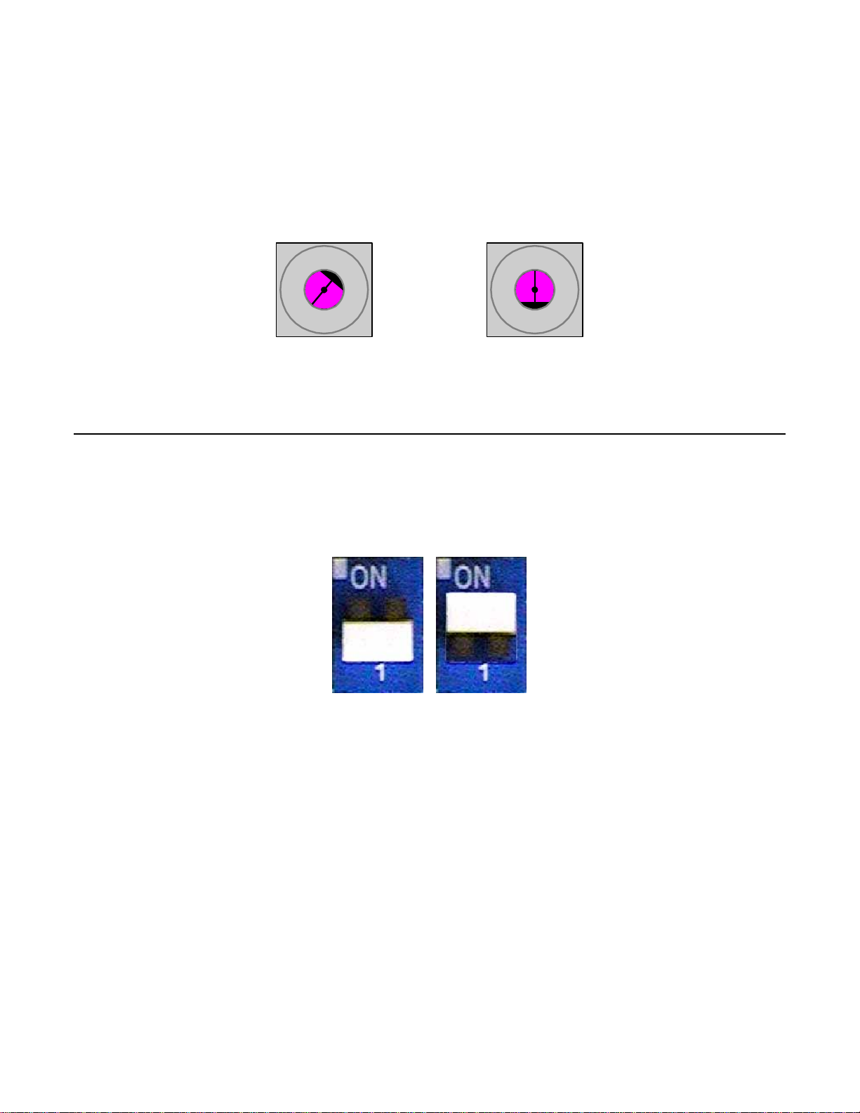
Set Node Address
Set the node address for the drive setting the 10‘s digit with S2 and the 1’s digit with S1. All devices on the network must have unique node
addresses. Check the network layout to verify that the node address selected is unique, matches the master configuration for that device and
falls between 3 – 9 9.
Address = (Switch 2 x 10) + (Switch 1 x 1)
Example: Set node address to 15
Set address switch 2 to "1 Set address switch 1 to "5"
0
1
9
6
S2
2
3
4
5
8
7
Figure 1.5 – Setting the V7 PROFIBUS-DP Option Node Address
0
1
9
6
S1
2
3
4
5
8
7
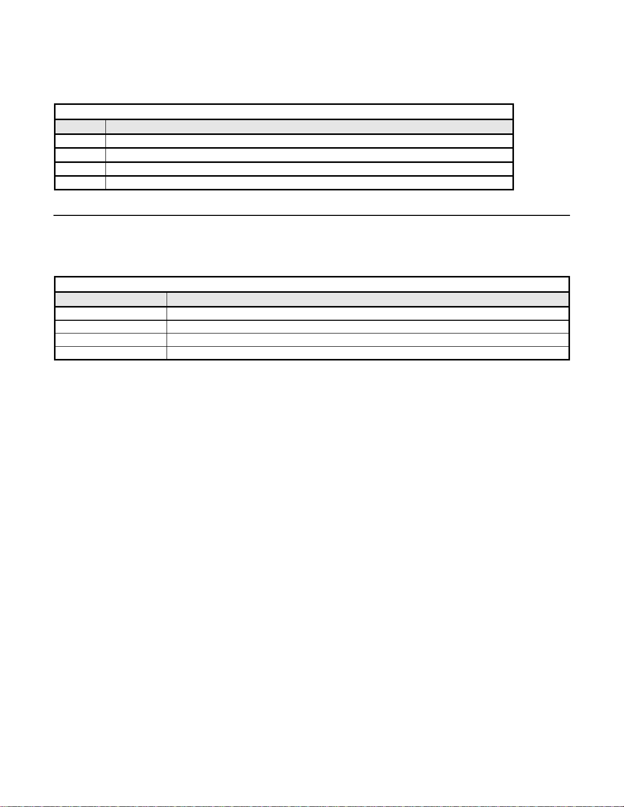
Set Network Termination
If this unit is either the first or the last device on the network, including any PLC and/or PROFIBUS-DP Master, and active termination is
not used, set the termination resistor switch to ON. If this device is not the first or last device on the network or active termination is used,
set the termination resistor switch to OFF. Active termination is the recommended termination method and is required for networks
operating above 1.5Mbps. Active termination will eliminate the possibility of network failure due to the removal of a terminated device.
The Siemens Active terminator Module part number is 6ES7 972-0DA00-0AA0.
OFF
Figure 1.6 – Termination Switch
ON
Installation 1-9
Page 16

Verify V7 PROFIBUS-DP Option Operation
Apply power to the drive.
Verify that the diagnostic LEDs on the front of the V7 PROFIBUS-DP Option are in their correct state.
Table 1.4 – Correct Diagnostic LED States
LED Display
PWR COM ERR WD
Solid Green Solid Green OFF Flashing Green Normal Normal communication possible.
Remove power from the drive and wait for the charge lamp to be com pletely extinguished. Wait at least five additional minutes
for the drive to be completely discharged. Measure the DC bus voltage and verify that it is at a safe level.
Secure the communication option to the drive, aligning the recessed screw at the top-center of the option with the threaded hole
in the mounting bracket.
Install the operator keypad and terminal cover.
Set drive parameters n003, n004 and n035 to appropriate values.
Table 1.5 – Option Specific Parameter Settings
Addr Param Function Data +/- Limits - Description Default
103h n003 Operation Method Selection
104h n004 Reference Selection
123h n035 Frequency Reference Unit Selection
Content Cause
0 Operator keypad
1 Terminal
2 Serial Communication
3
Option Card (PROFIBUS-DP Option)
0 Operator keypad Pot
1 Operator keypad
2 Voltage Reference (0-10v)
3 Current Reference (4-20 Ma)
4 Current Reference (0-20 Ma)
5 Pulse Train Reference
6 Serial Communication
7 Multi-Function Analog Input (0-10vdc)
8 Multi-Function Analog Input(4-20ma)
9
Option Card (PROFIBUS-DP Option)
0 0.01 Hz (< 100hz), 0.1hz (100 Hz >=100hz)
1 0.1%
2-39 Rpm
40-3999 User Setting
1
2
0
Installation 1-10
Page 17

Option LEDs
The PROFIBUS-DP Option Unit is equipped with four indication LEDs for module and PROFIBUS-DP status indication. The LEDs are
located on the unit according to the figure’s below.
Indicator LEDs
ERR
COMM
PWR
WD
Figure 1.8 – V7 PROFIBUS-DP LED Locations
LED Indicators
The following LEDs indicates the PROFIBUS-DP status.
Table 1.6 – Communication LEDs
LED Color Indication/Function
COMM Green Lit during data exchange with the PROFIBUS-DP Master .
ERR Red Lit when no data exchange is taken place.
Module Status Indicators
The following LEDs indicates the status of the V7 PROFIBUS-DP Option.
Table 1.7 – Diagnostic LEDs
LED Color Indication/Function
PWR Green Lit when the +5V power to the electronics is OK. Turned off if the +5V is below +4.5V (min)
WD Red/Green
Indicates the module status
OFF Communication Option CPU not running.
Solid Green: Initialization.
Flashing green: Normal operation.
Solid Red: Internal Communication Option error.
Flashing red: V7 error detected.
Other indication Unspecified, Communication Option error
Installation 1-11
Page 18

LED Diagnostics
The following table presents the faults displayed by the LEDs on the communication option, their causes, and solutions.
Table 1.8 – LED Diagnostics
LED Display
PWR COM ERR WD
OFF OFF OFF OFF
Solid
Green
Solid
Green
Solid
Green
Solid
Green
Solid
Green
Solid
Green
OFF
OFF
OFF
Solid
Green
Solid
Green
Solid
Green
Solid
Red
Solid
Red
Flashing
Red
Flashing
Red
OFF
OFF
Solid
Red
Flashing
Red
Solid
Green
Solid
Green
Solid
Green
Flashing
Green
Content Cause Solutions
Power
OFF
CPU
Error
Drive
Error
Com
Error
Com
Error
CPU
Init
Normal
Power is not being supplied
from the drive.
Power is not being supplied to
the option unit due to poor
option unit connection.
Option unit CPU error.
Error in Drive unit.
A fault has occurred rendering
communication impossible.
A fault has occurred rendering
communication impossible.
Option unit under initialization
Normal communication
possible.
• Check the main circuit wiring on the drive.
• Cycle drive power.
• Turn of the drive power .
• Check the option unit connection to the
drive.
• Cycle drive power.
• Cycle drive power.
• Replace option unit if fault persists.
• Cycle drive power.
• Replace V7 PROFIBUS-DP Option if fault
persists
• Replace drive if fault persists.
• Check whether the address set in the
PROFIBUS-DP Master differs from the
address of the option unit.
• Check that the master is functioning
properly.
• Check that the termination resistor is
correctly connected to the communication
line.
• Check whether the communication line is
correctly connected (disconnected or poor
connection).
• Check that the communication line is
separated from the main power line.
• Check whether the address is duplicated
with any other devices within the
PROFIBUS-DP network.
• Wait until WD LED is flashing
Installation 1-12
Page 19

Drive Faults
The following is a table of faults caused by the communication option that will be displayed on the V7 Operator Keypad, their causes, and
possible solutions. For any fault displayed on the operator that is not listed in the following table, please see the V7 Technical Manual.
Table 1.9 – Drive Faults
Fault Content Cause Solution
BUS Option Com Error
EF0 External Fault from Option
F06 Option Connection Fault
F21
F22
F23
Communication Option Selfdiagnostic Fault
Com Option Model Code No.
Fault
Com Option Mutual Diagnostic
Fault
Communication is not established
between PROFIBUS-DP Master and
the drive.
External fault is active from
PROFIBUS-DP option.
The drive and communication are not
correctly connected.
Communication option is not working.
• Check PROFIBUS-DP communication LED display.
• Turn OFF external fault input.
• Turn OFF the drive power supply and check the connection
of the option unit and drive, and then, turn ON the drive
power supply. If the fault persists, change the option unit.
• Turn the drive power supply back ON. If the fault persists,
replace the option unit.
Installation 1-13
Page 20

Parameter Settings
The following sections describe the parameters in the V7 that affect communications through the PROFIBUS-DP Communication Option.
For complete information on V7 drive parameters refer to the V7 MODBUS
®
T echnical Manual.
Run/Stop and Frequency Selection
The run/stop and frequency reference commands can originate from serial communication, the operator keypad, external terminals, or the
PROFIBUS-DP Option. Parameter n003 (Operation Method Selection) allows the selection of the origin of the run/stop commands.
Parameter n004 (Reference Selection) allows the selection of the origin of the frequency reference. The run/stop and frequency reference
commands may have different origins. The run/stop command may be set to External Terminals (n003 = 1) while the Frequency Reference
may be set to Option Card (PROFIBUS-DP Option) (n004 = 9).
Table 1.10 – Operation Method Selection
n003 Operation Method Selection (Run/Stop)
0 Operator keypad
1 External Terminals (Default setting is 1)
2 Serial Communication
3 Option Card (PROFIBUS-DP Option)
Table 1.11 – Frequency Reference Source Selection
n004 Frequency Reference Selection
0 Operator keypad Pot
1 Operator keypad
2 Voltage Reference (0-10V) (Default setting is 2)
3 Current Reference (4 to 20 mA)
4 Current Reference (0 to 20 mA)
5 Pulse Train Reference
6 Serial Communications (Parameter Access)
7 Multi- Function Analog Input (0 to 10V)
8 Multi-Function Analog Input (4 to 20mA)
9 Option Card (PROFIBUS-DP Option)
Installation 1-14
Page 21
Operator Display Mode
Parameter n035 sets the scaling and units of the frequency reference and output frequency on the operator keypad.. It also determines the
scaling and units of the Speed Command, Speed Reference, and Output Frequency used by the PROFIBUS-DP Option
Table 1.12 – Operator keypad Display Mode
n035 Description
0 0.1hz
1 0.1%
2 – 39 RPM (number of motor poles)
40 - 3999 User setting
Frequency Reference Units
Parameter n152 sets the resolution of the frequency reference and output frequency monitor. The output frequency resolution of the
operator keypad is settable via n035, Frequency Reference Unit Selection. If the operator keypad resolution is set to 0.1 Hz (n035=0), and
the resolution is changed to 0.01 Hz in n152, the value in the hundredths digit rounded off when displayed on the operator keypad.
Table 1.13 – Frequency Reference Unit Selection
n152 Frequency Reference Unit Selection
0 0.1 Hz (Default setting is 0)
1 0.01 Hz
2 100% / 30,000
3 0.1%
Installation 1-15
Page 22

This page intentionally left blank.
Installation 1-16
Page 23

Chapter 2 Network Configuration
This chapter provides an example configuration using the COM PROFIBUS
configuration utility from Siemens. It also explains the differences between the
three station configurations.
Configuration..................................................................... 2 - 3
GSD File ............................................................................. 2 - 6
Network Configuration 2-1
Page 24

This page intentionally left blank
Network Configuration 2-2
Page 25

Configuration
Once the V7 PROFIBUS-DP Option has been installed and the drive parameters set appropriately, it is necessary to add the drive to the
PROFIBUS-DP network through the use of a configuration tool. This tool is usually supplied by the vendor that supplied the PROFIBUSDP Master controller. This section provides a general overview of how to select the appropriate drive configuration. The Siemens COM
PROFIBUS configuration tool is used in the examples. The examples and descriptions below assume familiarity with both PROFIBUS-DP
network and setting up a PROFIBUS-DP Master for the devices on that network.
The PROFIBUS-DP Communication Option can be configured as one of three possible I/O configurations, 16 word input/output, 6 word
input/output and 3 word I/Os, combined input/output, messages. The structure of each message is described in Chapter 3 – Network
Communications.
Configure Master Device
Copy the GSD file from the CD that came with the V7 PROFIBUS-DP Option to the GSD sub-directory under the COM
PROFIBUS directory. The GSD file may also be downloaded from
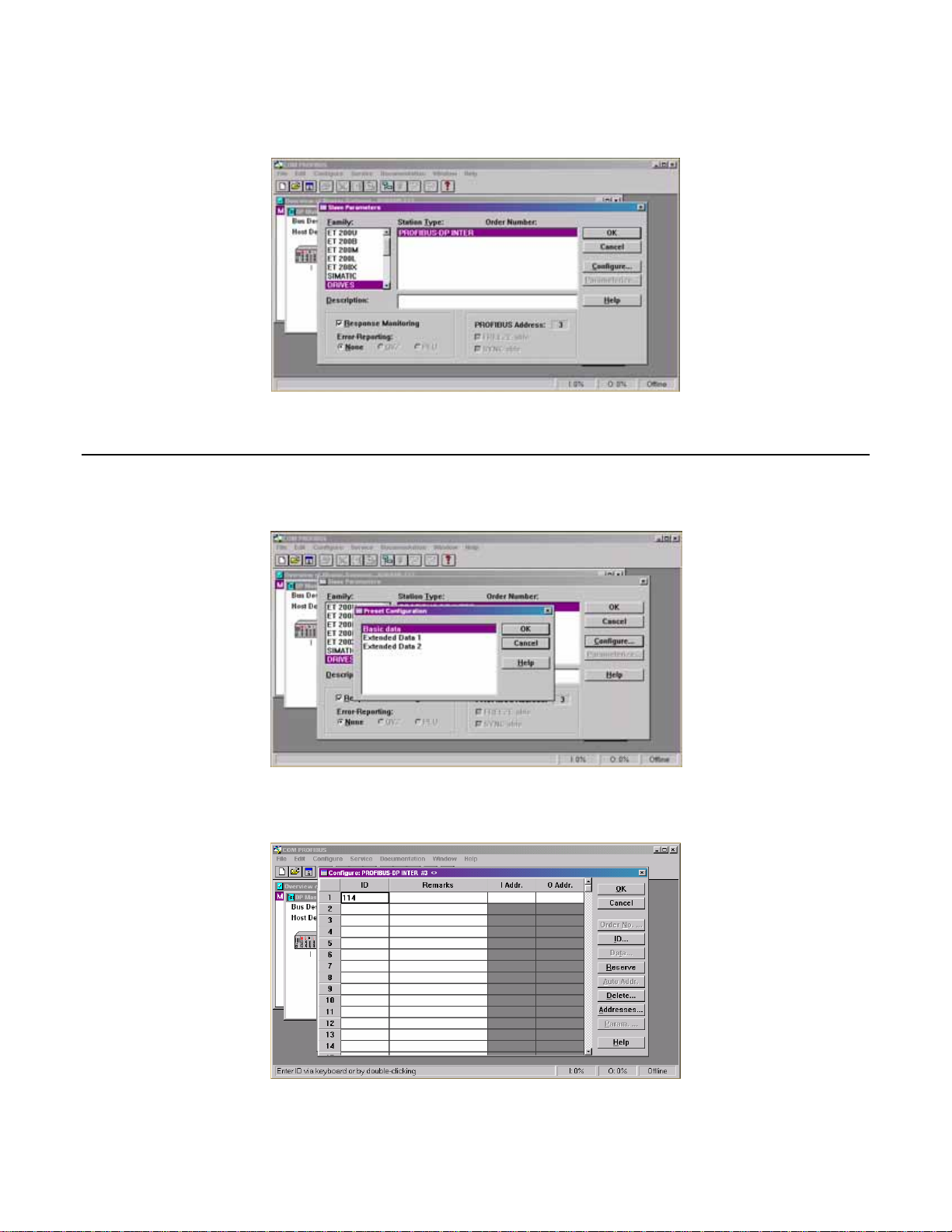
Open COM PROFIBUS and configure the Master device. A Siemens 545-1104 is used in this example.
Select the DRIVES block from the list of available devices. The cursor should change to Move the cursor to below
the icon representing the Master device and press the left mouse button.
http://www.drives.com
Figure 2.1 – Select Drive
Select Drive Address
A list box will appear displaying the available addresses for the drive. Select an address for the drive and click on the OK button. The
address selected must match the address switch setting on the V7 PROFIBUS-DP Option for the drive selected. Refer to the engineering
documentation or network schematic to determine which address is applicable for the drive selected.
Figure 2.2 – Select Address
Network Configuration 2-3
Page 26
Select Station Type
Select the appropriate station type from the list displayed. The V7 PROFIBUS-DP Option is listed as PROFIBUS-DP INTER. Highlight
the selection and click on the Configure button.
Figure 2.3 – Select Station Type
Station Configuration
Select the configuration desired. Basic Data consists of 3 word I/Os, combined input/output. Extended Data 1 consists of 16 input words
and 16 output words. Extended Data 2 consists of 6 input words and 6 output words.
Figure 2.4 – Select Configuration
The Basic Data configuration consists of 6 words of combined I/O. 3 input words and 3 output words. Refer to 3 Word I/O
Message section of Chapter 3 for a detailed description of the Basic Data configuration .
Figure 2.5 – Basic Data Configuration
Network Configuration 2-4
Page 27
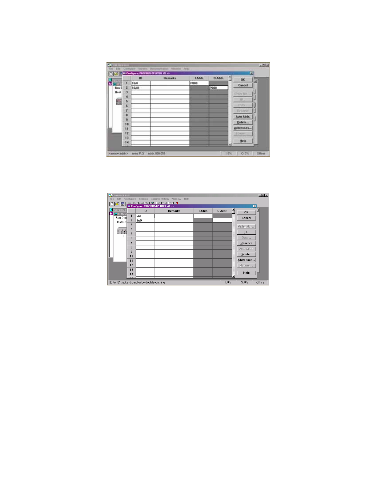
The Extended Data 1 configuration consists of 16 input words and 16 output words. Refer to 16 Word Input/Output Message
section of Chapter 3 for a detailed description of the Extended Data 1 configuration. This configuration is also used on those V7
PROFIBUS-DP Options that have an Option Name SI-P/V7 or Code Numbers prior to 73606-7110. The Option Name and Code
Number are located on the right side of the option.
Figure 2.6 – Extended Data 1 Configuration
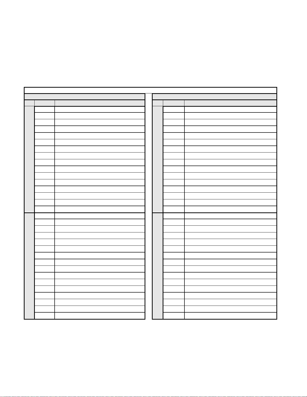
The Extended Data 2 configuration consists of 6 input words and 6 output words. Refer to 6 W ord Input/Output Message section
of Chapter 3 for a detailed description of the Extended Data 2 configuration. This configuration is also used on those V7
PROFIBUS-DP Options previously released as Profibus II.
Figure 2.6 – Extended Data 2 Configuration
Network Configuration 2-5
Page 28

GSD File
The listing of the current GSD file is shown below. The GSD file name is YASK00CA.GSD. The file is listed for information purposes only. Do not attempt to
modify the GSD file in any way.
;=====================================================================
; Device description file according to DIN 19245 Part 3 (PROFIBUS-DP)
;=====================================================================
;; FILENAME : YASK00CA_Rev1YEA.GSD
;--------------------------------------------------------------------; DEVICENAME : PROFIBUS-DP INTERFACE CARD SI-P1
;--------------------------------------------------------------------; PROTOCOL : PROFIBUS-DP slave
;--------------------------------------------------------------------; VENDOR : Yaskawa Electric
;--------------------------------------------------------------------; DATE : 06 June 2001
;--------------------------------------------------------------------; MODIFICATIONS : 06 June 2001, rev. 3.0 Created
; 08 April 2002, TW,rev 3.3 Revised for customer compatibility
;;=====================================================================
#PROFIBUS_DP
GSD_Revision = 1
Vendor_Name = "YASKAWA ELECTRIC"
Model_Name = "PROFIBUS-DP INTERFACE CARD SI-P1"
Revision = "Version 3.3"
Ident_Number = 0x00CA
Protocol_Ident = 0
Station_Type = 0
FMS_supp = 0
Hardware_Release = "Version 1.3"
Software_Release = "Version 3.3"
9.6_supp = 1
19.2_supp = 1
45.45_supp = 1
93.75_supp = 1
187.5_supp = 1
500_supp = 1
1.5M_supp = 1
3M_supp = 1
6M_supp = 1
12M_supp = 1
MaxTsdr_9.6 = 60
MaxTsdr_19.2 = 60
MaxTsdr_45.45 = 250
MaxTsdr_93.75 = 60
MaxTsdr_187.5 = 60
MaxTsdr_500 = 100
MaxTsdr_1.5M = 150
MaxTsdr_3M = 250
MaxTsdr_6M = 450
MaxTsdr_12M = 800
Redundancy = 0
Repeater_Ctrl_Sig = 2
24V_Pins = 0
Implementation_Type = "SPC3"
Freeze_Mode_supp = 1
Sync_Mode_supp = 1
Auto_Baud_supp = 1
Set_Slave_Add_supp = 0
Min_Slave_Intervall = 1
Modular_Station = 1
Max_Module = 1
Max_Input_Len = 32
Max_Output_Len = 32
Max_Data_Len = 64
Modul_Offset = 1
Fail_Safe = 0
Slave_Family = 1
Max_Diag_Data_Len = 6
Module = "Basic data" 0x72
EndModule
Module = "Extended Data 1" 0x5F, 0x6F
EndModule
Module = "Extended Data 2" 0x55, 0x65
EndModule
Network Configuration 2-6
Page 29

Chapter 3 Network Communications
This chapter describes in detail the composition of the three station types.
16 Word Input/Output Messages...................................... 3 - 3
6 Word Input/Output Messages........................................ 3 - 7
3 Word I/Os Messages .................................................... 3 - 10
Parameter Access Error Messages................................ 3 - 12
Handshaking.................................................................... 3 - 13
Network Communications 3-1
Page 30

This page intentionally left blank.
Network Communications 3-2
Page 31
16 Word Input/Output Message
The V7 PROFIBUS-DP Option can be configured as one of three possible I/O configurations; 16 word input/output message, 6 word
input/output message and 3 word I/Os, combined input/output, messages. The 16 word input/output message structure is described in this
section.
The 16 word input and output messages are divided into two areas. The first 16 bytes of each message is fixed. This is the most frequently
used data and is referred to as the fast I/O data. The remaining 16 bytes of each message are used for reading from and writing to all other
drive parameters and is referred to as parameter data. All command, monitor, and parameter data in the drive is accessible via the
Parameter Access portion of the message.
Table 3.1 – V7 PROFIBUS-DP 16 Word Input/Output Message Table
Output Data (PROFIBUS-DP Master-> V7) Input Data (V7 -> PROFIBUS-DP Master )
Byte Function Byte Function
0 RUN Operation Command MSB 0 Drive Status MSB
1 RUN Operation Command LSB 1 Drive Status LSB
2 Frequency Reference MSB 2 Reserved
3 Frequency Reference LSB 3 Reserved
4 Reserved 4 Reserved
5 Reserved 5 Reserved
6 Reserved 6 Reserved
7 Reserved 7 Reserved
8 Reserved 8 Frequency Reference MSB
9 Reserved 9 Frequency Reference LSB
Fast I/O Area
10 Reserved 10 Output Frequency MSB
11 Reserved 11 Output Frequency LSB
12 Reserved 12 Output Current MSB
13 Reserved 13 Output Current LSB
14 Multifunction Digital Output MSB 14 Main Speed Pulse Train Command MSB
15 Multifunction Digital Output LSB
Function Code
16
17 Starting Address MSB 17 Starting Address MSB
18 Starting Address LSB 18 Starting Address LSB
19 Data Length (2, 4, 6 or 8 bytes of data) 19 Data Length (2, 4, 6 or 8 bytes of data)
20 Data 1 MSB 20 Data 1 MSB
21 Data 1 LSB 21 Data 1 LSB
22 Data 2 MSB 22 Data 2 MSB
23 Data 2 LSB 23 Data 2 LSB
24 Data 3 MSB 24 Data 3 MSB
25 Data 3 LSB 25 Data 3 LSB
26 Data 4 MSB 26 Data 4 MSB
Parameter Access Area
27 Data 4 LSB 27 Data 4 LSB
28 Reserved 28 Reserved
29 Reserved 29 Reserved
30 Reserved 30 Reserved
31 Handshake Register
Fast I/O Area
15 Main Speed Pulse Train Command LSB
16
Function Code
Parameter Access Area
31 Handshake Register
Network Communications 3-3
Page 32

Fast I/O Output Data
The fast I/O output data area is used to transfer parameter data directly to the drive via a dual port RAM interface. The following table
details the functions of the fast I/O output data (Bytes 0 to 15) For detailed explanation of the terminal and multi-function inputs and
outputs, refer to the V7 Technical Manual.
Table 3.2 – 16 Word Input/Output Message Fast I/O Output Data
Fast I/O Output Data (PROFIBUS-DP Master -> V7)
Byte Function Bit Note
0 Fwd Run/Stop 1 = RUN Forward (Enabled when n003 is set to 3)
1 Rev Run/Stop 1 = RUN Reverse (Enabled when n003 is set to 3)
2 Terminal S3 1 = Close (terminal function dependent on setting of parameter n052)
0
Command
Reference
1
2 Frequency Reference MSB
Frequency
Reference
3
4 - 13 Reserved Must be set 0
Multi-Function
14
Output
Reserved
15
3 Terminal S4 1 = Close (terminal function dependent on setting of parameter n053)
4 Terminal S5 1 = Close (terminal function dependent on setting of parameter n054)
5 Terminal S6 1 = Close (terminal function dependent on setting of parameter n055)
6 Terminal S7 1 = Close (terminal function dependent on setting of parameter n056)
7 Reserved
8 External Fault 1 = External Error
9 Fault Reset 1 = Reset Fault
Ah - Fh Reserved
0.01Hz
Frequency Reference LS
0
Terminal MA MB MC 1 = Close (terminal function dependent on setting of parameter n057)
1
Terminal P1-PC 1 = Close (terminal function dependent on setting of parameter n058)
2
Terminal P2-PC 1 = Close (terminal function dependent on setting of parameter n059)
3 - Fh
Reserved
scaling is dependent on the setting of parameter n035
Network Communications 3-4
Page 33

Fast I/O Input Data
The fast I/O input data area is used to transfer parameter data directly from the drive via a dual port RAM interface. The following table
details the functions of the fast I/O input data (Bytes 0 to 15). For detailed explanation of the terminal and multi-function inputs and
outputs, refer to the V7 Technical Manual.
Table 3.3 – 16 Word Input/Output Message Fast I/O Input Data
Fast I/O Input Data (V7 -> PROFIBUS-DP Master )
Byte Function Bit Note
0 Running
1 @ Zero Speed
2 @ Reverse
0
Drive
Status
1
2 - 7 Reserved Always 0
8 Frequency Reference MSB
Frequency
Reference
9
10 Output Frequency MSB
Output
Frequency
11
12 Output Current MSB
Output
Current
13
Frequency
14 Pulse Train MSB
Reference
Pulse Train
15
Terminal PR
3 Reset Signal
4 @ Frequency Agree
5 Drive Ready (Rdy)
6 Minor Fault
7 Major Fault
8 OPE Error
9 Fault Restart
10 Local/Remote
11 Multi-function Output 1 1 = Close (terminal function dependent on setting of parameter n057)
12 Multi-function Output 2 1 = Close (terminal function dependent on setting of parameter n058)
13 Multi-function Output 3 1 = Close (terminal function dependent on setting of parameter n059)
14 Reserved
15 Reserved
0.01Hz
Frequency Reference LSB
Output Frequency LSB
Output Current LSB
Pulse train LSB
scaling is dependent on the setting of parameter n035
0.01Hz
scaling is dependent on the setting of parameter n035
0.1A
Parameter Access Area
This area is used to read and write parameter data from and to the drive. The PROFIBUS-DP Master completes the Parameter Access
command (output) message and waits for and then processes the data returned in the Parameter Access response (input) message. These
messages may contain 1 - 4 words of data. The handshaking byte is used to synchronize the communications between the PROFIBUS-DP
Master and the drive. This is necessary due to the additional time required for the drive to process the message. Refer to the Handshaking
section of this chapter for more information on handshaking. Note: Care must be taken when writing certain parameters to the V7 drive as
other parameters may be dependant on them. Control method, n002, maximum Frequency, n011, and Acc/Dec Scale Time, n018, are just a
few parameters whose setting will affect other parameter’s settings or ranges.. Refer to V7 MODBUS
information.
Network Communications 3-5
®
T echnical Manual for more
Page 34

Parameter Access Command Message Structure
Two command, output, functions are available, read parameter data, 03h, and write parameter data, 10h. If no parameter access
communications is desired, use 00h as the function code. These function codes are programmed in byte 16 of the 16 word input/output
message. Bytes 17 and 18 contain the parameter access address of the parameter to be accessed. Byte 19 contains the number of data bytes
to be read from or written to the drive. Since each parameter consists of two bytes, this value is incremented by two for each parameter
accessed. Bytes 19 through 27 contain the data to be written to the selected parameter. If the command is to read parameter data, bytes 19
through 27 must be set to 0.
Table 3.4 – 16 Word Input/Output Message Parameter Access Command Structure
Output Data – Parameter Access Command Message (PROFIBUS-DP Master -> V7)
Byte Name Function
16 Function Code
17 Starting Address MSB
18 Starting Address LSB
19 Data Quantity Bytes of data (2 x Number of parameters to be read or written)
20 Data 1 MSB
21 Data 1 LSB
22 Data 2 MSB
23 Data 2 LSB
24 Data 3 MSB
25 Data 3 LSB
26 Data 4 MSB
27 Data 4 LSB
28 Reserved
29 Reserved
30 Reserved
31 Handshaking Register Synchronizes drive communication with PROFIBUS-DP Master
Parameter Access Command Code (Read data = 03h, Write data = 10h)
The first register to be read or written
Value of data to write to the drive parameter Starting Address
Value of data to write to the drive parameter Starting Address + 1
Value of data to write to the drive parameter Starting Address + 2
Value of data to write to the drive parameter Starting Address + 3
Parameter Access Response Message Structure
The standard Parameter Access response structure is described below. In a non-erroneous response, the Function Code, Starting Register
and Data Quantity are identical to the command messa ge. If the command function code is 03h, read data, the data bytes will contain the
values of the requested parameters. If the command function code is 10h, write data, the data bytes will contain 0 and should be ignored.
Table 3.5 – 16 Word Input/Output Message Parameter Access Response Structure
Input Data – Parameter Access Response Message (V7 -> PROFIBUS-DP Master )
Byte Name Function
16 Function Code
17 Starting Address MSB
18 Starting Address LSB
19 Data Quantity Bytes of data (2 x Number of parameters to be read or written)
20 Data 1 MSB
21 Data 1 LSB
22 Data 2 MSB
23 Data 2 LSB
24 Data 3 MSB
25 Data 3 LSB
26 Data 4 MSB
27 Data 4 LSB
28 Reserved
29 Reserved
30 Reserved
31 Handshaking Register Synchronizes drive communication with PROFIBUS-DP Master
Parameter Access Response Code (Command code or command code & 80h for error)
The first register to be read or written
Value of data read from the drive parameter Starting Address
Value of data read from the drive parameter Starting Address + 1
Value of data read from the drive parameter Starting Address + 2
Value of data read from the drive parameter Starting Address + 3
Network Communications 3-6
Page 35

6 Word Input/Output Message
The 6 word input and output messages are divided into two areas. The first 4 bytes of each message is fixed. This is the most frequently
used data and is referred to as the fast I/O data. The remaining 8 bytes of each message are used for reading from and writing to all other
drive registers and is referred to as parameter data. All command, monitor, and parameter data in the drive is accessible via the Parameter
Access portion of the message. . Note: Care must be taken when writing certain parameters to the V7 drive as other parameters may be
dependant on them. Control method, n002, maximum Frequency, n011, and Acc/Dec Scale Time, n018, are just a few. Refer to V7
MODBUS
The 6 word input and output messages was designed for situations where processor memory may be a factor in the number of PROFIBUSDP devices resident on the network.
Byte Function Byte Function
Fast I/O
Parameter Access
®
T echnical Manual for more information.
Table 3.7 – V7 PROFIBUS-DP 6 Word Input/Output Message I/O Table
Output Data (PROFIBUS-DP Master -> V7) Input Data (V7 -> PROFIBUS-DP Master )
0 RUN Operation Command MSB 0 Drive Status MSB
1 RUN Operation Command LSB 1 Drive Status LSB
2 Frequency Reference MSB 2 Frequency Feedback MSB
3 Frequency Reference LSB
Function Code
4
5 Starting Address MSB 5 Starting Address MSB
6 Starting Address LSB 6 Starting Address LSB
7 Data Length (always 2) 7 Data Length (always 2)
8 Data 1 MSB 8 Data 1 MSB
9 Data 1 LSB 9 Data 1 LSB
10 Reserved 10 Reserved
11 Reserved 11 Reserved
12 Handshake Register
Fast I/O
3 Frequency Feedback LSB
4
Function Code
Parameter Access
12 Handshake Register
Fast I/O Output Data
The fast I/O output data area is used to transfer parameter data directly to the drive via a dual port RAM interface. The following table
details the functions of the fast I/O output data (Bytes 0 to 3) For detailed explanation of the terminal and multi-function inputs and
outputs, refer to the V7 Technical Manual.
Table 3.8 – 6 Word Input/Output Message Fast I/O Output Data
Fast I/O Output Data (PROFIBUS-DP Master -> V7)
Byte Function Bit Note
0 Fwd Run/Stop 1 = RUN Forward (Enabled when n003 is set to 3)
1 Rev Run/Stop 1 = RUN reverse (Enabled when n003 is set to 3)
2 Terminal S3 1 = Close (terminal function dependent on setting of parameter n052)
0
Command
Reference
1
2 Frequency Reference MSB
Frequency
Reference
3
3 Terminal S4 1 = Close (terminal function dependent on setting of parameter n053)
4 Terminal S5 1 = Close (terminal function dependent on setting of parameter n054)
5 Terminal S6 1 = Close (terminal function dependent on setting of parameter n055)
6 Terminal S7 1 = Close (terminal function dependent on setting of parameter n056)
7 Reserved
8 External Fault 1 = External Error
9 Fault Reset 1 = Reset Fault
Ah – Fh Reserved
0.01Hz
Frequency Reference LSB
scaling is dependent on the setting of parameter n035
Network Communications 3-7
Page 36

Fast I/O Input Data
The fast I/O input data area is used to transfer parameter data directly from the drive via a dual port RAM interface. The following table
details the functions of the fast I/O input data (Bytes 0 to 3) For detailed explanation of the terminal and multi-function inputs and outputs,
refer to the V7 Technical Manual.
Table 3.9 – 6 Word input/Output Message Fast I/O Input Data
Fast I/O Input Data (V7 -> PROFIBUS-DP Master )
Byte Function Bit Note
0 Running
1 @ Zero Speed
2 @ Reverse
0
Drive
Status
1
2 Frequency Reference MSB
Frequency
Reference
3
3 Reset Signal
4 @ Frequency Agree
5 Drive Ready (Rdy)
6 Minor Fault
7 Major Fault
8 OPE Error
9 Fault Restart
10 Local/Remote
11 Multi-function Output 1 1 = Close (terminal function dependent on setting of parameter n057)
12 Multi-function Output 2 1 = Close (terminal function dependent on setting of parameter n058)
13 Multi-function Output 3 1 = Close (terminal function dependent on setting of parameter n059)
14 Reserved
15 Reserved
0.01Hz
Frequency Reference LSB
scaling is dependent on the setting of parameter n035
Parameter Access Area
This area is used to read and write parameter data from and to the drive. The PROFIBUS-DP Master completes the Parameter Access
command (output) message and waits for and then processes the data returned in the response (input) message. These messages may
contain 1 - 4 words of data. The handshaking byte is used to synchronize the communications between the PROFIBUS-DP Master and the
drive. This is necessary due to the additional time required for the drive to process the message.
Network Communications 3-8
Page 37

Parameter Access Command Message Structure
Two command, output, functions are available, read parameter data, 03h, and write parameter data, 10h. If no Parameter Access
communications is desired, use 00h as the function code. These function codes are programmed in byte 4 of the 6 word input/output
message. Bytes 5 and 6 contain the address of the parameter to be accessed. Byte 7 contains the number of data bytes to be read from or
written to the drive. Since only one parameter may be accessed at a time, this value must always be set to 2. Bytes 8 and 9 contain the data
to be written to the selected parameter. If the command is to read parameter data, bytes 8 and 9 must be set to 0.
Table 3.10 – 6 Word Input/Output Message Parameter Access Command Messages
Output Data – Parameter Access Command Message (PROFIBUS-DP Master -> V7)
Byte Name Function
4 Function Code
5 Starting Address MSB
6 Starting Address LSB
7 Data Quantity (Bytes of data (2 x Number of parameters to be read or written)
8 Data 1 MSB
9 Data 1 LSB
10 Reserved
11 Reserved
12 Handshaking Register Synchronizes drive communication with PROFIBUS-DP Master
Parameter Access Command Code (Read data = 03h, Write data = 10h)
The first register to be read or written
Value of data to write to the drive parameter Starting Address
Parameter Access Response Message Structure
The standard Parameter Access response structure is described below. In a non-erroneous response, the Function Code, Starting Address
and Data Quantity are identical to the command messa ge. If the command function code is 03h, read data, the data bytes will contain the
values of the requested registers. If the command function code is 10h, write data, the data bytes will contain 0 and should be ignored.
Table 3.11 – 6 Word Input/Output Message Parameter Access Response Structure
Input Data – Parameter Access Response Message (V7 -> PROFIBUS-DP Master )
Byte Name Function
4 Function Code
5 Starting Address MSB
6 Starting Address LSB
7 Data Quantity Bytes of data (2 x Number of parameters to be read or written) (always 2)
8 Data 1 MSB
9 Data 1 LSB
10 Reserved
11 Reserved
12 Handshaking Register Synchronizes drive communication with PROFIBUS-DP Master
Parameter Access Response Code (Command code or command code & 80h for error)
The first register to be read or written
Value of data read from the drive parameter Starting Address
Network Communications 3-9
Page 38

3 Word I/Os Message
The 3 word I/Os messages have only one fixed area. This is the most frequently used data and is referred to as the fast I/O data. 6 Byte
messages are used when processor memory is a critical factor in the network design. As shown below the 3 word I/Os message contains
only the minimum drive data.
Table 3.12 – V7 PROFIBUS-DP 3 Word Message I/O Table
OUTPUT DATA PROFIBUS-DP Master -> V7 INPUT DATA V7 -> PROFIBUS-DP Master
Byte Function Byte Function
0 RUN Operation Command MSB 0 Drive Status MSB
1 RUN Operation Command LSB 1 Drive Status LSB
2 Frequency Reference MSB 2 Frequency Reference MSB
3 Frequency Reference LSB 3 Frequency Reference LSB
Fast I/O
4 Torque Reference MSB 4 Torque Reference MSB
5 Torque Reference LSB
Fast I/O Output Data
The fast I/O output data area is used to transfer parameter data directly to the drive via a dual port RAM interface. The following table
details the functions of the fast I/O output data (Bytes 0 to 5) For detailed explanation of the terminal and multi-function inputs and outputs,
refer to the V7 Technical Manual.
Fast I/O
5 Torque Reference LSB
Table 3.13 – 3 Word Message Fast I/O Output Data
Fast I/O Output Data (PROFIBUS-DP Master -> V7)
Byte Function Bit Note
0 Fwd Run/Stop 1 = RUN Forward (Enabled when n003 is set to 3)
1 Rev Run/Stop 1 = RUN reverse (Enabled when n003 is set to 3)
2 Terminal S3 1 = Close (terminal function dependent on setting of parameter n052)
0
Command
Reference
1
2 Frequency Reference MSB
Frequency
Reference
3
4 Torque Reference MSB
Torque
Reference
5
3 Terminal S4 1 = Close (terminal function dependent on setting of parameter n053)
4 Terminal S5 1 = Close (terminal function dependent on setting of parameter n054)
5 Terminal S6 1 = Close (terminal function dependent on setting of parameter n055)
6 Terminal S7 1 = Close (terminal function dependent on setting of parameter n056)
7 Reserved
8 External Fault 1 = External Error
9 Fault Reset 1 = Reset Fault
Ah - Fh Reserved
1 = 0.01Hz or 1 = 1 RPM
Frequency Reference LSB
Torque Reference LSB
scaling is dependent on the setting of parameter n035
0 – 100%
Network Communications 3-10
Page 39
Fast I/O Input Data
This area is used to transfer parameter data directly from the drive dual port RAM interface. The following tables detail the functions of
the fast I/O input data (Bytes 0 to 5)
Table 3.14 – 3 Word Message Fast I/O Input Data
Fast I/O Input Data (V7 -> PROFIBUS-DP Master )
Byte Function Bit Note
0 Running
1 @ Zero Speed
2 @ Reverse
0
Drive
Status
1
2 Frequency Reference MSB
Frequency
Reference
3
4 Torque Reference MSB
Torque
Reference
5
3 Reset Signal
4 @ Frequency Agree
5 Drive Ready (Rdy)
6 Minor Fault
7 Major Fault
8 OPE Error
9 Fault Restart
10 Local/Remote
11 Multi-function Out put 1 1 = Close (terminal function dependent on setting of parameter n057)
12 Multi-function Output 2 1 = Close (terminal function dependent on setting of parameter n058)
13 Multi-function Output 3 1 = Close (terminal function dependent on setting of parameter n059)
14 Reserved
15 Reserved
0.01Hz
Frequency Reference LSB
Torque Reference LSB
scaling is dependent on the setting of parameter n035
0 – 100%
Network Communications 3-11
Page 40

Parameter Access Error Messages
Whenever there is an invalid parameter access message, the drive will respond with an error message containing the fault code for that
particular error. Parameter access pertains only to16 Word and 6 word messages.
16 Word Input/Output Message
If an erroneous Parameter Access message is sent to the drive, the drive will respond with a fault message. The MSB of byte 16 of the fault
response will be set. If the fault is a read parameter data fault, byte 16 of the response message will contain 83h, read parameter function
code 03h with the MSB set. If the fault is a write parameter data fault, byte 16 of the response message will contain 90h, write parameter
function code 10h with the MSB set. Byte 19 will contain 2 and byte 21 will contain the specific error code. Refer to Table 3.15 below for
description of the possible error codes.
6 Word Input/Output Message
If an erroneous Parameter Access message is sent to the drive, the drive will respond with a fault message. The MSB of byte 4 of the fault
response will be set. If the fault is a read parameter data fault, byte 4 of the response message will contain 83h, read parameter function
code 03h with the MSB set. If the fault is a write parameter data fault, byte 4 of the response message will contain 90h, write parameter
function code 10h with the MSB set. Byte 7 will contain 2 and byte 9 will contain the specific error code. Refer to Table 3.15 below for
description of the possible error codes.
Table 3.15 – Parameter Access Fault Message Response
Error Code Error Name Details
01h Function Error Invalid function code
02h Address Error Parameter starting address greater than 600h
03h Amount of Data Fault Read or Write less than 2 words or more than 4 words
21h Data Content Fault Parameter exceeds upper and lower limits
• Parameter change during running or under-voltage
22h Write Fault
• ENTER command was written during running
• Write attempted to read–only data or during under-voltage
• Write attempted during parameter data storage
Network Communications 3-12
Page 41

Handshaking
The handshaking register is necessary to synchronize the send/receive timing of parameter access message data between the PROFIBUSDP Master and the V7 PROFIBUS-DP Option. One register (byte 32 of the 16 word input/output message or byte 12 of the 6 word
input/output message) in the input and output parameter access message areas is dedicated to handshaking. The data set in the output area
of the master becomes enabled in the V7 PROFIBUS-DP Option when the status of the HS bit, bit 7, is changed.
Command Handshaking Register PROFIBUS-DP Master To V7
Table 3.16 – Handshaking Output Register Bit Definitions
Bit Name Function
7 HS
6 - 0
Response Handshake Register V7 To PROFIBUS-DP Master
Bit Name Function
7 HS Handshaking bit. Used to synchronize the data exchange. Toggled when a new response is transmitted
6 - 5 STATUS
4 - 1 WD Watch Dog Counter, incremented approximately every 64 ms.
0 Not used
Handshaking bit. Used to synchronize the data exchange. Toggled when a new command is transmitted. This bit must be
cleared after power-up or re-initialization by the Master program.
Not used.
Table 3.17 – Handshaking Input Register Bit Definitions
Status of data exchanged between Communication Option and drive.
00H: Idle
01H: Sending parameter access message to drive
10H: Waiting for parameter access response from drive
11H: Response received from drive
Network Communications 3-13
Page 42

This page intentionally left blank.
Network Communications 3-14
Page 43

Appendix A Product Specification
This appendix describes the specification for the PROFIBUS-DP Option interface
car.
Table A.1 – Product Specific ation
V7 PROFIBUS-DP Option
Ambient Temperature -10 to +45OC (14 to 113OF)
Storage Temperature -20 to +60OC (-4 to 140OF)
Relative Humidity Not to exceed 90% RH (non-condensing)
Altitude Not to exceed 1000m (3280ft)
Vibration
PROFIBUS-DP Specification PROFIBUS-DP Slave- EN 50170
PROFIBUS-DP Profile Vendor-Specific, PNO-approved
Connector Type 6-pin open-style screw connector
Physical Layer Type Isolated Physical Layer (RS485 transceiver + photo-coupler)
Node Address Setting 2 Decimal Rotary Switches: address 1 to 99
Baud Rate Auto-configure: 9600 bps to 12 Mbps
ASIC Implementation SPC 3
Feature Support Freeze Mode, Sync Mode, Auto Baud
1G (9.8m/s
0.2G (2m/s
2
) at 10 to 20Hz.
2
) at 20 to 50Hz.
Product Specification A-1
Page 44

This page intentionally left blank.
Product Specification A-2
Page 45

Appendix B Parameter Access
This appendix describes in detail how to read and write parameter data to and
from the V7 drive.
Parameter Access Overview............................................. B - 3
Read Drive Data Example................................................. B - 5
Read Drive Data Error Example........................................ B - 6
Write Drive Data Example................................................. B - 7
Write Drive Data Error Example ....................................... B - 8
Parameter Access B-1
Page 46

This page intentionally left blank.
Parameter Access B-2
Page 47

Parameter Access Overview
Parameter access allows the reading and writing of drive parameters. For a detailed description of the V7 drive parameters refer to the V7
MODBUS
®
T echnical Manual.
Initialize Data Structures
Prior to setting the command message, insure that the command message handshake byte HS, bit 7, bit matches the HS bit, bit 7, of the
response message.
Set PROFIBUS-DP Master Command Message
Function Code: Enter 03h (0000 0011) to read data from the drive or 10h (1010 0000) to write data to the drive. If no
parameter access messaging is required, enter 00h as the function code.
Addressing: All register addresses consist of two (2) bytes. The most significant byte, the upper half, is entered as the Starting
Address MSB. The least significant byte, the lower half, is entered as the S tarting Address LSB. If more than one V7 register is
to be accessed, only valid with 16 word input/output messages, the registers must be consecutive beginning with the register at
the starting address.
z Starting Address MSB: Enter the upper half of the starting address. For address 1234h, enter 12h.
z Starting Address LSB: Enter the lower half of the starting address. For address 1234h, enter 34h.
Data Quantity: Enter the quantity of data to either read or write. Each register contains 2 data bytes. To read or write 1
register, enter 2. To read or write 2 registers, enter 4. For 6 word input/output messages, 2 is the only valid entry.
Data: All drive register data consists of 2 bytes. The most significant byte, the upper half, of the value is contained in Data #
MSB. The least significant byte, the lower half, is contained in Data # LSB. For reading data from the drive, these registers must
be set to 0. For writing data to the drive, enter the data in the order that it is to be written to the drive at consecutive addresses
starting with the address entered as the Starting Address. For 16 word input/output messages, if data is to be written to 2 registers,
enter the appropriate values into Data 1 and Data 2. Data 3 and Data 4 must contain 0.
z Data # MSB: To read drive data, set this value to 0. To write data, enter the most significant byte, the upper half, of the data
to be written. To write data 5678h, enter 56h. To write more than one register, valid for 16 word input/output messages only,
the registers must be consecutive starting with the address entered as the Starting Address.
z Data # LSB: To read drive data, set this value to 0. To write data, enter the least significant byte, the lower half, of the data
to be written. To write data 5678h, enter 78h. To write more than one register, valid for 16 word input/output messages only,
the registers must be consecutive starting with the address entered as the Starting Address.
Handshaking: Set the HS bit, the MSB, bit 7, of the command message handshaking byte to the same state as the HS bit ,
the MSB, bit 7, of the response message handshaking byte.
Toggle the PROFIBUS-DP Master Handshake Bit
Toggle the command message Handshake MSB, the most significant bit, bit 7, to signal the drive that the command message contains a
valid parameter access section. Make sure that all data has been entered into the command message before setting this bit. It is advisable to
insert at least one processor scan between setting the command message and setting the handshake bit. Maintain the state of the HS bit until
another command is to be sent to the drive.
Message Received By PROFIBUS-DP Option - Ignore All Response Data
To signify the receipt of the command message, the PROFIBUS-DP Option will set the response message handshaking HS bit to match the
state of the command message handshaking HS bit. Depending on the scan time of the PROFIBUS-DP Master and the interval between
reviewing response messages, the PROFIBUS-DP Master may not see this response.
Parameter Access B-3
Page 48

Message Sent To Drive - Ignore All Response Data
The PROFIBUS-DP Option formats the Parameter Access command message and transmits it to the drive, setting bit 5 of the response
message handshake. Depending on the scan time of the PROFIBUS-DP Master and the interval between reviewing response messages, the
PROFIBUS-DP Master may not see this response.
Wait For Drive Response - Ignore All Response Data.
Upon receiving the Parameter Access message from the PROFIBUS-DP Option, the drive processes the message, setting bit 6 and resetting
bit 5 of the response message handshake. This processing typically takes 10ms to 15ms dependant on the state of the drive at the time of
receiving the message. Depending on the scan time of the PROFIBUS-DP Master and the interval between reviewing response messages,
the PROFIBUS-DP Master may not see this response.
Process Response – Store And Process Data
The response message handshake byte bits 5 and 6 are set to signal that the drive has completed processing the Parameter Access message.
If the command message was to read drive data, the data bytes will now contain valid data. If the command message was to write drive
data, the data has been successfully written.
Parameter Access B-4
Page 49

Read Drive Data Example
Table B.2 – Read Drive Data Example
PROFIBUS-DP Master Command Initialize Data Structures Drive Response
Function Code 00h Function Code 03h
Starting Address MSB 00h Starting Address MSB 01h
Starting Address LSB 00h Starting Address LSB 00h
Data Quantity 00h Data Quantity 02h
Data 1 MSB 00h Data 1 MSB 00h
Data 1 LSB 00h Data 1 LSB 00h
Handshaking (1000 0000) 80h
PROFIBUS-DP Master Command Set PROFIBUS-DP Master Command Message Drive Response
Function Code 03h Function Code 03h
Starting Address MSB 00h Starting Address MSB 01h
Starting Address LSB 37h Starting Address LSB 00h
Data Quantity 02h Data Quantity 02h
Data 1 MSB 00h Data 1 MSB 00h
Data 1 LSB 00h Data 1 LSB 00h
Handshaking (1000 0000) 80h
PROFIBUS-DP Master Command Toggle the PROFIBUS-DP Master Handshake Bit Drive Response
Function Code 03h Function Code
Starting Address MSB 00h Starting Address MSB
Starting Address LSB 37h Starting Address LSB
Data Quantity 02h Data Quantity
Data 1 MSB 00h Data 1 MSB
Data 1 LSB 00h Data 1 LSB
Handshaking (0000 0000) 00h
PROFIBUS-DP Master Command Wait for Response Drive Response
Function Code 03h Function Code
Starting Address MSB 00h Starting Address MSB
Starting Address LSB 37h Starting Address LSB
Data Quantity 02h Data Quantity
Data 1 MSB 00h Data 1 MSB
Data 1 LSB 00h Data 1 LSB
Handshaking (0000 0000) 00h
PROFIBUS-DP Master Command Wait for Response Drive Response
Function Code 03h Function Code
Starting Address MSB 00h Starting Address MSB
Starting Address LSB 37h Starting Address LSB
Data Quantity 02h Data Quantity
Data 1 MSB 00h Data 1 MSB
Data 1 LSB 00h Data 1 LSB
Handshaking (0000 0000) 00h
PROFIBUS-DP Master Command Process Response Drive Response
Function Code 03h Function Code 03h
Starting Address MSB 00h Starting Address MSB 00h
Starting Address LSB 37h Starting Address LSB 37h
Data Quantity 02h Data Quantity 02h
Data 1 MSB 00h Data 1 MSB 00h
Data 1 LSB 00h Data 1 LSB 15h
Handshaking (0000 0000) 00h
Set the command message handshake byte HS bit to the same state as the
response message handshake HS bit.
Set the Function Code, Starting Address, and Data Quantity. This
example configures the command message to retrieve data from drive
register at address 0037h, Output Power . For detailed information of
drive registers refer to the V7 Technical Manual and the V7 MODBUS
Technical Manual.
After the data bits have been set, toggle the HS bit, bit 7, of the command
handshake byte to signal the drive that the command message contains a
Parameter Access command. On receipt of the command message, the
HS bit, bit 7, of the response message handshake byte is set to the same
state as the HS bit of the command message handshake byte. As the
response message may contain invalid data, ignore all response message
data.
The PROFIBUS-DP Option formats the command message and transmits
it to the drive, setting bit 5 of the response handshake byte. As the
response message may contain invalid data, ignore all response message
data.
Bit 5 is reset and bit 6 set of the response handshake byte when the
message has been received by the drive and that the drive has begun
processing the message. As the response message may contain invalid
data, ignore all response message data.
Bits 5 and 6 of the response byte handshake are both set when the
processing has been completed and the response message contains valid
data.
®
Handshaking (1110 0000) E0h
Handshaking (1110 0000) E0h
Handshaking (0000 0000) 00h
Handshaking (0010 0000) 20h
Handshaking (0100 0000) 40h
Handshaking (0110 0000) 60h
Parameter Access B-5
Page 50

Read Drive Data Error Example
Table B.3 – Read Drive Data Error Example
PROFIBUS-DP Master Command Initialize Data Structures Drive Response
Function Code 00h Function Code 03h
Starting Address MSB 00h Starting Address MSB 01h
Starting Address LSB 00h Starting Address LSB 00h
Data Quantity 00h Data Quantity 02h
Data 1 MSB 00h Data 1 MSB 00h
Data 1 LSB 00h Data 1 LSB 00h
Handshaking (0000 0000) 00h
PROFIBUS-DP Master Command Set PROFIBUS-DP Master Command Message Drive Response
Function Code 03h Function Code 03h
Starting Address MSB 10h Starting Address MSB 01h
Starting Address LSB 00h Starting Address LSB 00h
Data Quantity 02h Data Quantity 02h
Data 1 MSB 00h Data 1 MSB 00h
Data 1 LSB 00h Data 1 LSB 00h
Handshaking (0000 0000) 00h
PROFIBUS-DP Master Command Toggle the PROFIBUS-DP Master Handshake Bit Drive Response
Function Code 03h Function Code
Starting Address MSB 10h Starting Address MSB
Starting Address LSB 00h Starting Address LSB
Data Quantity 02h Data Quantity
Data 1 MSB 00h Data 1 MSB
Data 1 LSB 00h Data 1 LSB
Handshaking (1000 0000) 80h
PROFIBUS-DP Master Command Wait for Response Drive Response
Function Code 03h Function Code
Starting Address MSB 10h Starting Address MSB
Starting Address LSB 00h Starting Address LSB
Data Quantity 02h Data Quantity
Data 1 MSB 00h Data 1 MSB
Data 1 LSB 00h Data 1 LSB
Handshaking (1000 0000) 80h
PROFIBUS-DP Master Command Wait for Response Drive Response
Function Code 03h Function Code
Starting Address MSB 10h Starting Address MSB
Starting Address LSB 00h Starting Address LSB
Data Quantity 02h Data Quantity
Data 1 MSB 00h Data 1 MSB
Data 1 LSB 00h Data 1 LSB
Handshaking (1000 0000) 80h
PROFIBUS-DP Master Command Process Response Drive Response
Function Code 03h Function Code 83h
Starting Address MSB 10h Starting Address MSB 00h
Starting Address LSB 00h Starting Address LSB 00h
Data Quantity 02h Data Quantity 02h
Data 1 MSB 00h Data 1 MSB 00h
Data 1 LSB 00h Data 1 LSB 02h
Handshaking (1000 0000) 80h
Set the command message handshake byte HS bit to the same state as the
response message handshake HS bit.
Set the Function Code, Starting Address, and Data Quantity. This
example configures the command message to retrieve data from drive
register at address 0037h, Output Power . For detailed information of
drive registers refer to the V7 Technical Manual and the V7 MODBUS
Technical Manual.. For the purposes of this example, an invalid Starting
Address was entered.
After the data bits have been set, toggle the HS bit, bit 7, of the command
handshake byte to signal the drive that the command message contains a
Parameter Access command. On receipt of the command message, the
HS bit, bit 7, of the response message handshake byte is set to the same
state as the HS bit of the command message handshake byte. As the
response message may contain invalid data, ignore all response message
data.
The PROFIBUS-DP Option formats the command message and transmits
it to the drive, setting bit 5 of the response handshake byte. As the
response message may contain invalid data, ignore all response message
data.
Bit 5 is reset and bit 6 set of the response handshake byte when the
message has been received by the drive and that the drive has begun
processing the message. As the response message may contain invalid
data, ignore all response message data.
Bits 5 and 6 of the response handshake byte are both set when the
processing has been completed and the response message contains valid
data. The MSB of the function code signifies an error response and Data
1 LSB contains the error code. Refer to Parameter Access Error
Messages section of Chapter 3
®
Handshaking (0110 0000) 60h
Handshaking (0110 0000) 60h
Handshaking (1000 0000) 80h
Handshaking (1010 0000) A0h
Handshaking (1100 0000) C0h
Handshaking (1110 0000) E0h
Parameter Access B-6
Page 51

Write Drive Data Example
Table B.4 – Write Drive Data Example
PROFIBUS-DP Master Command Initialize Data Structures Drive Response
Function Code 00h Function Code 03h
Starting Address MSB 00h Starting Address MSB 01h
Starting Address LSB 00h Starting Address LSB 00h
Data Quantity 00h Data Quantity 02h
Data 1 MSB 00h Data 1 MSB 00h
Data 1 LSB 00h Data 1 LSB 00h
Handshaking (1000 0000) 00h
PROFIBUS-DP Master Command Set PROFIBUS-DP Master Command Message Drive Response
Function Code 10h Function Code 03h
Starting Address MSB 01h Starting Address MSB 01h
Starting Address LSB 05h Starting Address LSB 00h
Data Quantity 02h Data Quantity 02h
Data 1 MSB 00h Data 1 MSB 00h
Data 1 LSB 01h Data 1 LSB 00h
Handshaking (0000 0000) 00h
PROFIBUS-DP Master Command Toggle the PROFIBUS-DP Master Handshake Bit Drive Response
Function Code 10h Function Code
Starting Address MSB 01h Starting Address MSB
Starting Address LSB 05h Starting Address LSB
Data Quantity 02h Data Quantity
Data 1 MSB 00h Data 1 MSB
Data 1 LSB 01h Data 1 LSB
Handshaking (1000 0000) 80h
PROFIBUS-DP Master Command Wait for Response Drive Response
Function Code 10h Function Code
Starting Address MSB 01h Starting Address MSB
Starting Address LSB 05h Starting Address LSB
Data Quantity 02h Data Quantity
Data 1 MSB 00h Data 1 MSB
Data 1 LSB 01h Data 1 LSB
Handshaking (1000 0000) 80h
PROFIBUS-DP Master Command Wait for Response Drive Response
Function Code 10h Function Code
Starting Address MSB 01h Starting Address MSB
Starting Address LSB 05h Starting Address LSB
Data Quantity 02h Data Quantity
Data 1 MSB 00h Data 1 MSB
Data 1 LSB 01h Data 1 LSB
Handshaking (1000 0000) 80h
PROFIBUS-DP Master Command Process Response Drive Response
Function Code 10h Function Code 10h
Starting Address MSB 01h Starting Address MSB 01h
Starting Address LSB 05h Starting Address LSB 05h
Data Quantity 02h Data Quantity 02h
Data 1 MSB 00h Data 1 MSB 00h
Data 1 LSB 01h Data 1 LSB 00h
Handshaking (1000 0000) 80h
Set the command message handshake byte HS bit to the same state as the
response message handshake HS bit.
Set the Function Code, Starting Address, and Data Quantity. This
example configures the command message to retrieve data from drive
register at address 0037h, Output Power . For detailed information of
drive registers refer to the V7 Technical Manual and the V7 MODBUS
Technical Manual.
After the data bits have been set, toggle the HS bit, bit 7, of the command
handshake byte to signal the drive that the command message contains a
Parameter Access command. On receipt of the command message, the
HS bit, bit 7, of the response message handshake byte is set to the same
state as the HS bit of the command message handshake byte. As the
response message may contain invalid data, ignore all response message
data.
The PROFIBUS-DP Option formats the command message and transmits
it to the drive, setting bit 5 of the response handshake byte. As the
response message may contain invalid data, ignore all response message
data.
Bit 5 is reset and bit 6 set of the response handshake byte when the
message has been received by the drive and that the drive has begun
processing the message. As the response message may contain invalid
data, ignore all response message data.
Bits 5 and 6 of the response handshake byte are both set when the
processing has been completed and the response message contains valid
data.
®
Handshaking (0110 0000) 60h
Handshaking (0000 0000) 00h
Handshaking (1000 0000) 80h
Handshaking (1010 0000) A0h
Handshaking (1100 0000) C0h
Handshaking (1110 0000) E0h
Parameter Access B-7
Page 52

Write Drive Data Error Example
Table B.5 – Write Drive Data Error Example
PROFIBUS-DP Master Command Initialize Data Structures Drive Response
Function Code 00h Function Code 03h
Starting Address MSB 00h Starting Address MSB 01h
Starting Address LSB 00h Starting Address LSB 00h
Data Quantity 00h Data Quantity 02h
Data 1 MSB 00h Data 1 MSB 00h
Data 1 LSB 00h Data 1 LSB 00h
Handshaking (1000 0000) 80h
PROFIBUS-DP Master Command Set PROFIBUS-DP Master Command Message Drive Response
Function Code 10h Function Code 03h
Starting Address MSB 10h Starting Address MSB 00h
Starting Address LSB 00h Starting Address LSB 37h
Data Quantity 02h Data Quantity 02h
Data 1 MSB 00h Data 1 MSB 00h
Data 1 LSB 01h Data 1 LSB 00h
Handshaking (1000 0000) 80h
PROFIBUS-DP Master Command Toggle the PROFIBUS-DP Master Handshake Bit Drive Response
Function Code 10h Function Code
Starting Address MSB 10h Starting Address MSB
Starting Address LSB 00h Starting Address LSB
Data Quantity 02h Data Quantity
Data 1 MSB 00h Data 1 MSB
Data 1 LSB 01h Data 1 LSB
Handshaking (0000 0000) 00h
PROFIBUS-DP Master Command Wait for Response Drive Response
Function Code 10h Function Code
Starting Address MSB 10h Starting Address MSB
Starting Address LSB 00h Starting Address LSB
Data Quantity 02h Data Quantity
Data 1 MSB 00h Data 1 MSB
Data 1 LSB 01h Data 1 LSB
Handshaking (1000 0000) 00h
PROFIBUS-DP Master Command Wait for Response Drive Response
Function Code 10h Function Code
Starting Address MSB 10h Starting Address MSB
Starting Address LSB 00h Starting Address LSB
Data Quantity 02h Data Quantity
Data 1 MSB 00h Data 1 MSB
Data 1 LSB 01h Data 1 LSB
Handshaking (0000 0000) 00h
PROFIBUS-DP Master Command Process Response Drive Response
Function Code 10h Function Code 90h
Starting Address MSB 10h Starting Address MSB 00h
Starting Address LSB 00h Starting Address LSB 00h
Data Quantity 02h Data Quantity 02h
Data 1 MSB 00h Data 1 MSB 00h
Data 1 LSB 01h Data 1 LSB 22h
Handshaking (0000 0000) 80h
Set the command message handshake byte HS bit to the same state as the
response message handshake HS bit.
Set the Function Code, Starting Address, and Data Quantity. This
example configures the command message to retrieve data from drive
register at address 0037h, Output Power . For detailed information of
drive registers refer to the V7 Technical Manual and the V7 MODBUS
Technical Manual. For the purposes of this example an invalid Starting
Address was used.
After the data bits have been set, toggle the HS bit, bit 7, of the command
handshake byte to signal the drive that the command message contains a
Parameter Access command. On receipt of the command message, the
HS bit, bit 7, of the response message handshake byte is set to the same
state as the HS bit of the command message handshake byte. As the
response message may contain invalid data, ignore all response message
data.
The PROFIBUS-DP Option formats the command message and transmits
it to the drive, setting bit 5 of the response handshake byte. As the
response message may contain invalid data, ignore all response message
data.
Bit 5 is reset and bit 6 set of the response handshake byte when the
message has been received by the drive and that the drive has begun
processing the message. As the response message may contain invalid
data, ignore all response message data.
Bits 5 and 6 of the response handshake byte are both set when the
processing has been completed and the response message contains valid
data. The MSB of the function code signifies an error response and Data
1 LSB contains the error code. Refer to Parameter Access Error Message
section of Chapter for error code description.
®
Handshaking (0110 0000) 60h
Handshaking (1110 0000) E0h
Handshaking (0000 0000) 00h
Handshaking (0010 0000) 20h
Handshaking (0100 0000) 40h
Handshaking (0110 0000) 60h
Parameter Access B-8
Page 53

Appendix C Troubleshooting
This chapter is a basic troubleshooting guide. For detailed information on the V7
drive refer to the V7 Technical Manual. Detailed information on PROFIBUS-DP
can be obtained from www.profibus.com
Troubleshooting Check List............................................. C - 3
Installation Troubleshooting............................................. C - 5
Wiring And Cabling ........................................................... C - 8
PROFIBUS-DP Configuration ........................................ C - 11
V7 PROFIBUS-DP Interface Diagnostics....................... C - 12
.
Troubleshooting C-1
Page 54

This page intentionally left blank.
Troubleshooting C-2
Page 55

Troubleshooting Check List
1: The V7 drive operates correctly without the PROFIBUS-DP Option installed
Drive model number ______________
2: The V7 PROFIBUS-DP Option is correctly and securely installed on the drive
PROFIBUS-DP Option Code number ______________
3: All network devices have unique addresses and drives are addressed between 1 and 99
Drive address____________
S1 _______
S2 _______
4: The Run/Stop command source parameter, n003, is set correctly
n003 ____________
5: The Frequency Reference command source parameter, n004, is set correctly
n004 ____________
6: The correct cable type is used. Mfg.____________________ PN____________________
7: All cable connections are correct per device schematic and are secure
8: All cables have been checked for continuity. There are no breaks or shorts.
9: Cable length between nodes is at least 1 meter
10: Maximum segment and maximum network lengths do not exceed the maximum allowed
11: The total stub lengths do not exceed the maximum allowed
12: There are no more than 32 devices on each segment, including repeaters and controllers.
There are no more than 31 devices on each segment if no repeaters are used.
13: The network is correctly terminated on each end and only at each end.
14: The shield is continuous throughout the network and is properly grounded on each end.
15: The network cable is routed away from any high voltage cable(s) or source(s).
16: The correct GSD fie is used. GSD file name ________________________________.GSD
17: The controller scan list is configured to send and receive the correct amount of data.
18: The PROFIBUS-DP LEDs are in their correct on/off states.
19: All network devices have been tested for conformance with the PROFIBUS-DP specification.
WARNING
Do not attempt to disassemble this unit. There are no user serviceable parts. Disassembling this unit will void any and all
warranties.
Troubleshooting C-3
Page 56

This page intentionally left blank.
Troubleshooting C-4
Page 57

Installation Troubleshooting
The following is a short guide to troubleshooting V7 PROFIBUS-DP Option installation. It highlights some of the most common issues
faced when diagnosing and correcting issues associated with the startup and operation of a V7 drive with a PROFIBUS-DP industrial
network. Further information on the features of each interface can be found in the V7 PROFIBUS-DP Option Technical Manual. While
most of the information is centered on the application of V7, the guidelines presented are applicable in most PROFIBUS-DP Networks.
Diagnosis of network fault issues will typically fall into three categories: installation of the PROFIBUS-DP option, wiring and cabling
issues, and network configuration/diagnostics. Each of these areas will be discussed below to help resolve common problems associated in
PROFIBUS-DP network troubleshooting.
Drive Operates Correctly Without Network Option Installed
Before installing any drive option, verify that the drive functions properly without the option installed. Refer to the V7 Technical
Manual, for information on the drive’s installation and operation.
The PROFIBUS-DP Option Is Properly Installed.
Verify that the connection between CN1 and CN3 on the PROFIBUS-DP Option are securely connected to CN2 and CN1, respectively, on
the V7 drive. Verify that the four locking tabs on the PROFIBUS-DP Option are engaged and that the option is fully seated and flush on top
of the V7
Verify And Write Down The Code Number Of The PROFIBUS-DP Option.
The Code Number can be found on the nameplate on the side of the PROFIBUS-DP Option and specifies the version of the interface unit.
This Code Number is necessary to select the proper GSD file. It will also be useful if technical support should become necessary.
Option Code Number
Option Name
Program
Lot Number & Mass
Serial Number
CODE NO : 73606- V7030
PRG :
LOT NO :
SER NO :
Figure C.1 – Option Nameplate
INTE R FACE UNI T SI- P1/ V 7
YASKAWA ELECTRIC CORPORATION
MASS : 0.5kg
MADE IN JAPAN
M
S
Troubleshooting C-5
Page 58
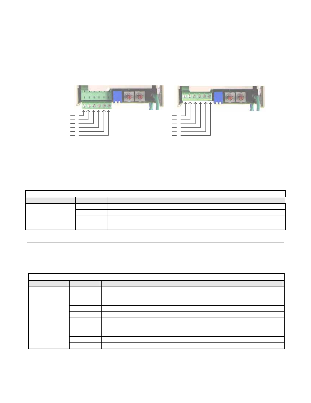
Network Cable Is Connected Correctly
Determine the type of connector on the V7 PROFIBUS-DP Option. Connector Style A is an extended Phoenix connector. The
extension can be seen on the back of the connector as a small circuit board. Connector Style B is a standard phoenix connector
without any modifications.
Connect the PROFIBUS-DP network cable to the V7 PROFIBUS-DP Option. Refer to the appropriate connection drawing in
Figure C.2 below for your connector style.
Use standard PROFIBUS-DP cable as specified by the PROFIBUS Organization.
Connector Style A Connector Style B
A In (Green)
B In (RED)
A Out (Green)
B Out (RED)
Shield
Reserved
1
2
3
4
5
6
Reserved
Reserved
A In/Out (Green)
B In/Out (RED)
Shield
Reserved
1
2
3
4
5
6
Figure C.2 – V7 PROFIBUS-DP Option Connections
Run/Stop Operation Parameter Is Set Correctly.
Parameter n003 needs to be set to the source of the V7’s Run/Stop command. If the V7 receives the Run/Stop command from the
PROFIBUS-DP network, parameter n003 must be set to “3 – Option Card”. Refer to the V7 Technical Manual for further explanation of
this parameter.
Table C.1 - V7 Run/Stop Reference Source
Parameter Value Description
0 Operator Keypad
n003
1 External Terminals
2 Serial Communications
3 Option Card (PROFIBUS-DP Communications)
Frequency Reference Parameter Is Set Correctly
Parameter n004 needs to be set to the source of the V7’s frequency reference command. If the V7 receives its frequency reference from the
PROFIBUS-DP network, parameter n004 must be set to “9 – Option Card”. Refer to the V7 Technical Manual for further explanation of
this parameter.
Parameter Value Description
0 Operator keypad
1 Parameter n024
2 Voltage Reference (0 – 10 vdc)
3 Current Reference (4 – 20 ma)
n004
4 Current Reference (0 – 20 ma)
5 Pulse Train Reference
6 Serial Communications
7 Multi-function analog Input (1 – 10 vdc)
8 Multi-function Analog Input (4 – 20 ma)
9 Option Card (PROFIBUS-DP Communications)
Table C.2 - V7 Frequency Reference Source
Troubleshooting C-6
Page 59
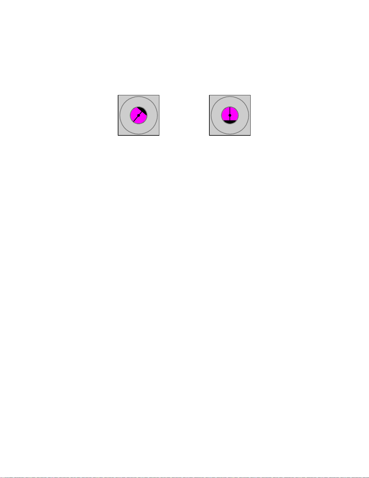
The Network Address Correct And Unique.
Each device on the network must have a unique address. Valid addresses are 1 through 99 with 1 typically reserved for the PROFIBUS-DP
Master and 2 reserved for diagnostic equipment. Set the V7 network address via rotary switches S1(x1) and S2(x10). To set a V7 to address
15, set S2 to 1 and S1 to 5.
Address = (Switch 2 x 10) + (Switch 1 x 1)
Example: Set node address to 15
Set address switch 2 to "1 Set address switch 1 to "5"
0
1
9
6
S2
2
3
4
5
8
7
Figure C.3 – V7 PROFIBUS-DP Option Addressing
0
1
9
6
S1
2
3
4
5
8
7
Troubleshooting C-7
Page 60

Wiring And Cabling
Several serial communications troubleshooting issues can be traced to cabling and grounding. The V7 PROFIBUS-DP Option is based on
RS485 differential line technology, and specifies the cable to be used, i.e. cable length requirements, termination requirements, number of
nodes allowed per segment, etc. The following lists and describes the items that should be checked during the network installation to verify
correct cabling and grounding. Failure to follow the following guidelines could result in total or intermittent communications failure.
The Network Cable Is The Correct Type.
The cable used by the PROFIBUS-DP network is specified by PROFIBUS European Standard EN50170. It is a shielded, twisted pair cable
with the following specifications. In order for the cable to fit the currently available PROFIBUS-DP standard connectors, the surrounding
diameter must be 8.0mm (+/- 0.5 mm).
Table C.3 – PROFIBUS-DP Cable Specifications
Parameter PROFIBUS-DP Cable Requirements
Impedance 135 to 165 Ohm / 3 to 20Mhz
Capacitance < 30 pF / m
Resistance < 110 Ohm / Km
Wire Gauge > 0.64 mm
Conductor Area > 0.34 mm2
Shield Density Greater than 80%
Cable Is Correctly And Securely Connected
Check for shorts, broken wires, loose connections, and that the signal and shield wires are connected to the correct pin on the option
connector. See Figure C.3 – V7 PROFIBUS-DP Option Connections above for required wiring.
Cable Lengths Are Within Specified Limit s
Both data rate and cable type affect the total allowable length of the network. The total amount of measured linear cable allowed between
any two points on the network segment must be within the following table’s specification. Also, the total amount of network length,
allowed through segment repeaters must be less than the Maximum Network Length in the following table. The minimum distance of
cable that is required between device connections to the PROFIBUS-DP physical media is a distance of one (1) meter.
Table C.4 – PROFIBUS-DP Cable Length Specifications
Baud Rate Maximum Segment Length Maximum Network Length
9.6 Kbps 1,200 Meters 10,000 Meters
187.5 Kbps 1,000 Meters 10,000 Meters
500.0 Kbps 400 Meters 4,000 Meters
1.5 Mbps 200 Meters 2,000 Meters
3.0 Mbps 100 Meters 1,000 Meters
6.0 Mbps 100 Meters 1,000 Meters
12.0 Mbps 100 Meters 1,000 Meters
Troubleshooting C-8
Page 61

Stub Lengths Are W ithin Specified Limit s
The total amount of measured linear cable allowed between the point of the stub connection (from the main PROFIBUS-DP cable) to the
node connection on the line, along with the cumulative total or sum of all stub cable length(s) must not exceed the maximum specified.
When calculating stub lengths, include stub in the device itself. Use 1cm for each V7 drive. The following table and diagram specifies the
stub length requirements. DO NOT use stubs when the PROFIBUS-DP network is configured to operate at baud rates above
1.5Mbps
Table C.5 – PROFIBUS-DP Stub Length Specifications
Baud Rate Total Capacitance for all Stubs Total Stub Length
9.6 Kbps 15.0 nF 500 Meters
187.5 Kbps 3.0 nF 100 Meters
500.0 Kbps 1.0 nF 33 Meters
1.5 Mbps 0.6 nF 20 Meters
3.0 Mbps 0.2 nF Approx. 0
6.0 Mbps Stubs Not Allowed Approx. 0
12.0 Mbps Stubs Not Allowed Approx. 0
There Are No More Than 32 Total Devices On Each Network Segment.
This means that only 31 physical devices can be connected on one PROFIBUS-DP network segment without a repeater.
Verify that there are no more than 31 physical nodes on the network segment, which includes all Master/PLC connections,
slave devices, and configuration nodes for all connections. If there are more than 31 devices, you must add a repeater
between the network segments to separate the devices into two separate copper buses. Note, the reason for using RS485
repeaters is for allowing more than 32 devices to talk to one Master PLC port, or there is a need to operate bus segments as
ungrounded with reference to each other , or the network segment exceeds the maximum length per the operating baud rate.
Up to nine (9) RS485 repeaters can be used in cascade (in-line).
The Network Is Terminated Correctly.
A PROFIBUS-DP network copper bus segment is based on an RS485 standard and requires two (2) and only two (2), termination resistors
of 120 ohms, ¼ watt, at each of the furthest ends of the PROFIBUS-DP cabling. Typically, a good place for the termination resistors to be
ON is at the PLC connector (only, if the network segment starts at that point) and, at the last device on the network segment. This is to keep
transmission signal distortion to a minimum along all sections of the network bus.
If the last device on the network is a drive, the termination switch on the PROFIBUS-DP Option may be used. Set the switch to
the ON position.
Active Termination Devices are the preferred method of terminating the network. They must be continually powered to function
correctly and must be used for transmission rates above 1.5 Mbps. The Siemens P/N for the Active Terminator Module is 6ES7
972-0DA00-0AA0.
Figure C.4 – V7 PROFIBUS-DP Option Termination Settings
OFF
ON
Troubleshooting C-9
Page 62

Common Mode Voltage Between Any Two Points Is Less Than 7vdc.
RS485 requires that the common mode voltage be less than 7vdc. Large voltage potential differences between points on the network, may
cause equalization current flow in the shield. This interferes with the PROFIBUS-DP signal quality. If common mode voltage is greater
than 7vdc, a separate ground conductor must connect the network devices to a central ground point, typically at the start of the segment.
Shield Is Continuous And Both Ends Of The Sh ield Are Grounded.
The cable shields, between all nodes of the network segment shall be connected, to form a single conduction path throughout the segment.
The shield must then be grounded at each endpoint
Cable Is Routed Correctly
The PROFIBUS-DP network cable must not run parallel to or close to any high power or high frequency cables. A minimum clearance of
4” – 10” is required, depending on the level of voltage or signals in the cables. If network cables must cross high power or frequency
cables, they must do so at a 90 deg angle.
Troubleshooting C-10
Page 63

PROFIBUS-DP Configuration
In order for the V7 drive with the V7 PROFIBUS-DP Option to operate in a PROFIBUS-DP networked system, the PROFIBUS-DP master
must be configured to recognize the V7 drive on the network. Typically, the master scan list is setup and modified with a PROFIBUS-DP
configuration utility, such as COM PROFIBUS from Siemens. The configuration utility is typically provided by the vendor supplying the
PROFIBUS-DP master.
The V7 drive is a slave device and requires a master PROFIBUS-DP scanner to communicate on a PRFIBUS-DP network. The V7 drive
configuration entered into the master scan list, via the configuration utility, must match exactly the configuration built into the V7
PROFIBUS-DP Option. The V7 drive has diagnostic LEDs to annunciate the state of the PROFIBUS-DP network.
Correct GSD file is used.
The configuration utility uses the GSD file to set certain parameters, including the Identification Number, the number of Input and Output
words, the supported baud rates, etc. The GSD file is stored in the GSD sub-directory under the directory where COM PROFIBUS was
originally installed. The “Scan GSD Files” option under the “File” menu can be used to load the GSD file information in COM
PROFIBUS if it has not already loaded. In COM PROFIBUS, for example, the Station Type PROFIBUS INTER selects the V7
PROFIBUS-DP Option.
The filename of the current version of the GSD file, that is used for the V7 PROFIBUS-DP Option is, “YASK00CA.gsd”. This GSD file
can be found at
www.drives.com .
Master Scan List Is Setup Correctly
Verify that the PROFIBUS-DP Master scan list is configured to send and receive the correct amount of data to each node on the
PROFIBUS-DP network and that the PROFIBUS-DP Master has the devices correctly mapped in memory. There are several PROFIBUSDP scanners on the market today. Some support the configuration tools mentioned above and some have their own configuration tools.
Refer to the manufacturer’s documentation for determining how to verify and program the scan list settings in the PROFIBUS-DP Master.
The size and type of information expected from the PROFIBUS-DP Master scanner must match exactly (per the GSD file) the device
configuration. Determine that the PROFIBUS-DP Master operational words to and from the PROFIBUS-DP device are mapped into the I/O
space of the PROFIBUS-DP Master. For each specific PROFIBUS-DP Master, this I/O mapping may be different. Consult the PROFIBUSDP Master documentation to insure correct I/O mapping.
V7 PROFIBUS-DP Option Configuration
With PROFIBUS-DP INTER selected as the Station Type, three configuration selections will be displayed. Select the configuration
applicable to the particular application. Basic Data consists of 3 word I/Os message (3 input words and 3 output words). Extended Data 1
consists of 16 input words and 16 output words. Extended Data 2 consists of 6 input words and 6 output words.
The Basic Data configuration consists of 3 words of combined I/O. 3 input words and 3 output words. Refer to 3 Word I/O
Message section of Chapter 3 for a detailed description of the Basic Data configuration .
The Extended Data 1 configuration consists of 16 input words and 16 output words. Refer to 16 Word Input/Output Message
section of Chapter 3 for a detailed description of the Extended Data 1 configuration. This configuration is also used on those V7
PROFIBUS-DP Options that have an Option Name SI-P/V7 or Code Numbers prior to 73606-7110. The Option Name and Code
Number are located on the right side of the option.
The Extended Data 2 configuration consists of 6 input words and 6 output words. Refer to 6 W ord Input/Output Message section
of Chapter 3 for a detailed description of the Extended Data 2 configuration. This configuration is also used on those V7
PROFIBUS-DP Options referred to as Profibus II.
Troubleshooting C-11
Page 64

V7 PROFIBUS-DP Option Diagnostics
The PROFIBUS-DP Option Is Operating Correctly
Verify that the PROFIBUS-DP interface unit on the V7 drive is operating correctly, by reporting the state of the LEDs on the Interface Unit.
The drawing below shows the indication LEDs as they appear on the PROFIBUS-DP interface unit.
Indicator LEDs
ERR
COMM
PWR
WD
Figure C.5 – V7 PROFIBUS-DP LED Locations
LED Indicators
The following LEDs indicates the PROFIBUS-DP status.
Table C.6 – Communication LEDs
LED Color Indication/Function
COMM Green Lit during data exchange with the PROFIBUS-DP Master .
ERR Red Lit when no data exchange is taken place.
Troubleshooting C-12
Page 65

Module Status Indicators
The following LEDs indicates the status of the V7 PROFIBUS-DP Option.
Table C.7 – Diagnostic LEDs
LED Color Indication/Function
PWR Green Lit when the +5V power to the electronics is OK.
WD Red/Green
Turned off if the +5V is below +4.5V (min)
Indicates the module status
OFF Communication Option CPU not running.
Solid Green: Initialization.
Flashing green: Normal operation.
Solid Red: Internal Communication Option error.
Flashing red: V7 error detected.
Other indication Unspecified, Communication Option error
LED Diagnostics
The following table presents the faults displayed by the LEDs on the communication Option, their causes, and countermeasures.
Table C.8 – LED Diagnostics
LED Display
PWR COM ERR WD
OFF OFF OFF OFF
Solid
Green
Solid
Green
Solid
Green
Solid
Green
Solid
Green
Solid
Green
OFF
OFF
OFF
Solid
Green
Solid
Green
Solid
Green
Solid
Red
Solid
Red
Flashing
Red
Flashing
Red
OFF
OFF
Solid
Red
Flashing
Red
Solid
Green
Solid
Green
Solid
Green
Flashing
Green
Content Cause Counter measures
Power
OFF
CPU
Error
Drive
Error
Com
Error
Com
Error
CPU
Init
Normal
Power is not being supplied
from the drive.
Power is not being supplied to
the option unit due to poor
option unit connection.
Option unit CPU error.
Error in Drive unit.
A fault has occurred rendering
communication impossible.
A fault has occurred rendering
communication impossible.
Option unit under initialization
Normal communication
possible.
• Check the main circuit wiring on the drive.
• Cycle drive power.
• Turn of the drive power .
• Check the option unit connection to the
drive.
• Cycle drive power.
• Cycle drive power.
• Replace option unit if fault persists.
• Cycle drive power.
• Replace drive if fault persists.
• Check whether the address set in the
PROFIBUS-DP Master differs from the
address of the option unit.
• Check that the master is functioning
properly.
• Check that the termination resistor is
correctly connected to the communication
line.
• Check whether the communication line is
correctly connected (disconnected or poor
connection).
• Check that the communication line is
separated from the main power line.
• Check whether the address is duplicated
with any other devices within the
PROFIBUS-DP network.
• Wait until WD LED is flashing
Troubleshooting C-13
Page 66

Drive Faults
The following is a table of drive faults that could be caused by the V7 PROFIBUS-DP Option that will be displayed on the V7 Operator
Keypad, their causes, and possible solutions. For any fault displayed on the operator that is not listed in the following table, please see the
V7 T echnical Manual.
Table 1.9 – Drive Faults
Fault Content Cause Solution
BUS Option Com Error
EF0 External Fault from Option
F06 Option Connection Fault
F21
F22
F23
Communication Option Selfdiagnostic Fault
Com Option Model Code No.
Fault
Com Option Mutual Diagnostic
Fault
Communication is not established
between PROFIBUS-DP Master and
the drive.
External fault is active from
PROFIBUS-DP option.
The drive and communication are not
correctly connected.
Communication option is not
working.
• Check PROFIBUS-DP communication LED display.
• Turn OFF external fault input.
• Turn OFF the drive power supply and check the connection
of the option unit and drive, and then, turn ON the drive
power supply. If the fault persists, change the option unit.
• Turn the drive power supply back ON. If the fault persists,
change the option unit.
Troubleshooting C-14
Page 67

Page 68

V7 PROFIBUS-DP® Option
YASKAWA ELECTRIC AMERICA, INC.
Drives Division
16555 W. Ryerson Rd., New Berlin, WI 53151, U.S.A.
Phone: (800) YASKAWA (800-927-5292) Fax: (262) 782-3418
Internet: http://www.drives.com
YASKAWA ELECTRIC AMERICA, INC.
Chicago-Corporate Headquarters
2121 Norman Drive South, Waukegan, IL 60085, U.S.A.
Phone: (800) YASKAWA (800-927-5292) Fax: (847) 887-7310
Internet: http://www.yaskawa.com
MOTOMAN INC.
805 Liberty Lane, West Carrollton, OH 45449, U.S.A.
Phone: (937) 847-6200 Fax: (937) 847-6277
Internet: http://www.motoman.com
YASKAWA ELECTRIC CORPORATION
New Pier Takeshiba South Tower, 1-16-1, Kaigan, Minatoku, Tokyo, 105-0022, Japan
Phone: 81-3-5402-4511 Fax: 81-3-5402-4580
Internet: http://www.yaskawa.co.jp
YASKAWA ELETRICO DO BRASIL COMERCIO LTDA.
Avenida Fagundes Filho, 620 Bairro Saude Sao Paolo-SP, Brasil CEP: 04304-000
Phone: 55-11-5071-2552 Fax: 55-11-5581-8795
Internet: http://www.yaskawa.com.br
YASKAWA ELECTRIC EUROPE GmbH
Am Kronberger Hang 2, 65824 Schwalbach, Germany
Phone: 49-6196-569-300 Fax: 49-6196-888-301
MOTOMAN ROBOTICS AB
Box 504 S38525, Torsas, Sweden
Phone: 46-486-48800 Fax: 46-486-41410
MOTOMAN ROBOTEC GmbH
Kammerfeldstrabe 1, 85391 Allershausen, Germany
Phone: 49-8166-900 Fax: 49-8166-9039
YASKAWA ELECTRIC UK LTD.
1 Hunt Hill Orchardton Woods Cumbernauld, G68 9LF, Scotland, United Kingdom
Phone: 44-12-3673-5000 Fax: 44-12-3645-8182
YASKAWA ELECTRIC KOREA CORPORATION
Paik Nam Bldg. 901 188-3, 1-Ga Euljiro, Joong-Gu, Seoul, Korea
Phone: 82-2-776-7844 Fax: 82-2-753-2639
YASKAWA ELECTRIC (SINGAPORE) PTE. LTD.
Head Office: 151 Lorong Chuan, #04-01, New Tech Park Singapore 556741, Singapore
Phone: 65-282-3003 Fax: 65-289-3003
TAIPEI OFFICE (AND YATEC ENGINEERING CORPORATION)
10F 146 Sung Chiang Road, Taipei, Taiwan
Phone: 886-2-2563-0010 Fax: 886-2-2567-4677
YASKAWA JASON (HK) COMPANY LIMITED
Rm. 2909-10, Hong Kong Plaza, 186-191 Connaught Road West, Hong Kong
Phone: 852-2803-2385 Fax: 852-2547-5773
BEIJING OFFICE
Room No. 301 Office Building of Beijing International Club,
21 Jianguomanwai Avenue, Beijing 100020, China
Phone: 86-10-6532-1850 Fax: 86-10-6532-1851
SHANGHAI OFFICE
27 Hui He Road Shanghai 200437 China
Phone: 86-21-6553-6600 Fax: 86-21-6531-4242
SHANGHAI YASKAWA-TONJI M & E CO., LTD.
27 Hui He Road Shanghai 200437 China
Phone: 86-21-6533-2828 Fax: 86-21-6553-6677
BEIJING YASKAWA BEIKE AUTOMATION ENGINEERING CO., LTD.
30 Xue Yuan Road, Haidian, Beijing 100083 China
Phone: 86-10-6232-9943 Fax: 86-10-6234-5002
SHOUGANG MOTOMAN ROBOT CO., LTD.
7, Yongchang-North Street, Beijing Economic & Technological Development Area,
Beijing 100076 China
Phone: 86-10-6788-0551 Fax: 86-10-6788-2878
YEA, TAICHUNG OFFICE IN TAIWAIN
B1, 6F, No.51, Section 2, Kung-Yi Road, Taichung City, Taiwan, R.O.C.
Phone: 886-4-2320-2227 Fax:886-4-2320-2239
YEA Document Number: TM.V7.12 (Supercedes TM4322 and TM4323) 6/20/2002 Rev: 02-06
Data subject to change without notice. Yaskawa Electric America, Inc.
 Loading...