

Page 1

Over 100 years cumulative experience
24 hour rush turnaround / technical support service
Established in 1993
The leading independent repairer of servo motors and drives in North America.
Visit us on the web:
www.servo-repair.com
www.servorepair.ca
www.ferrocontrol.com
www.sandvikrepair.com
www.accuelectric.com
Scroll down to view your document!
For 24/7 repair services :
USA: 1 (888) 932 - 9183
Canada: 1 (905) 829 -2505
Emergency After hours: 1 (416) 624 0386
Servicing USA and Canada
Page 2

AC SERVO DRIVE M.F-S,D SERIES
I1 BULLETIN
WITH INCREMENTAL ENCODER, FOR SPEED CONTROL
SERVOMOTOR TYPES USAME-_D, USAFED, USASEM, USADED
SERVOPACK TYPES CACR-SRE-_BB1 ,r-__
YASKAWA TSE-S800-2.1J
Page 3
Yaskawa AC Servo Drives have been de- For your mechatronics systems, the flexi-
veloped as basic mechatronics drives for ble combination of our AC SERVOMOTOR i
the most advanced FA and FMS, includ- and SERVOPACK achieves stable control
inK robots and machine tools. The exten- operation with high accuracy, quick re-
sive servo manufacturing technology sponse control under any environmental
accumulated through a half century of condition, and smooth, powerful operation
servo drive applications has created and even at low-speed range. Some outstanding
nurtured a new phase of AC servo drives, features are as follows.
This man_ual covers AC servo drives "High accuracy and quick response
M, F, S and D series for speed control, forspeed control
The AC Servo Drives consist primarily -Compact design and high reliability
of AC SERVOMOTORS and their
controllers, SERVOPACKS. The AC "Light weight and high power
SERVOMOTOR features a high power -Highly reliable protective functions
rating for achieving quick response. -Selectable drive to meet users" require-
Custom LSI and hybrid ICs builtin ments
SERVOPACK reduce the unit size and
simplify wiring. The additional feature
of a highly accurate pluse resolution
offers non-stop pulse flow.
I
q
General Precautions
• Some drawings in this manual are shown with the protective cover or shields
removed, in order to describe the detail with more clarity. Make sure all covers
and shields are replaced before operating this product.
• This manual may be modified when necessary because of improvement of the
product, modification, or changes in specifications.
Such modification is made as a revision by renewing the manual No.
• To order a copy of this manual, if your copy has been damaged or lost, contact
your YASKAWA representative listed on the last page stating the manual No.
on the front cover.
• YASKAWA is not responsible for accidents or damages due to any modification
of the product made by the user since that will void our guarantee.
I
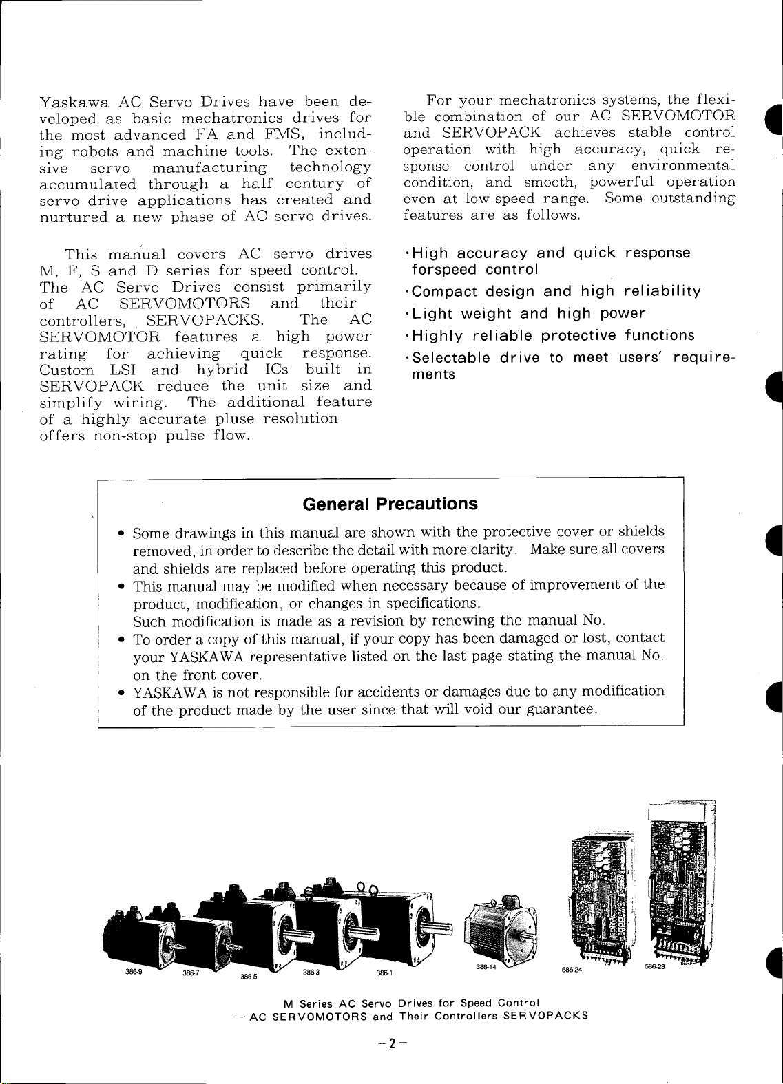
386-9 386-5 386-1 388-14 586-24 1
--AC SERVOMOTORS and Their Controllers SERVOPACKS
M Series AC Servo Drives for Speed Control
--2--
Page 4

D NOTES FOR SAFE OPERATION
Read this manual thoroughly before installation, operation, main-
tenance or inspection of the AC Servo Drives. In this manual, the
NOTES FOR SAFE OPERATION are classified as "WARNING" or
"CAUTION".
,,WARNING
Indicates a potentially hazardous situation which, if not avoided, could
D result in death or serious personal, injury.
CAUTION 1
Indicates a potentially hazardous situation which, if not avoided, may
D result in minor or moderate personal injury and/or damage to the
equipment.
In some instances, items described in /k CAUTION may also result
in a serious accident. In either case, follow these important items.
D
-3-
Page 5
,/K WARNING il
(Wll O)
• Grounding must be in accordance with the national code and consistent with
sound local practices.
Failure to observe this warning may lead to electric shock or fire.
(OPERATION)
• Never touch any rotating motor parts during operation.
Failure to observe this warning may result in personal injury.
(INSPECTION AND MAINTENANCE)
• Be sure to turn OFF power before inspection or maintenance.
Otherwise, electric shock may result.
• Never open the panel cover while power is ON, and never turn ON power when
the panel cover is open.
Otherwise, electric shock may result.
• After turning OFF power, wait at least five minutes before servicing the product.
Otherwise, residual electric charges may result in electric shock.
CAUTION
(RECEIVING)
• Use the specified combination of SERVOMOTOR and SERVOPACK.
Failure to observe this caution may lead to fire or failure.
(INSTALLATION)
• Never use the equipment where it may be exposed to splashes of water,
corrosive or flammable gases, or near flammable materials.
Failure to observe this caution may lead to electric shock or fire.
(WIRING)
• Do not connect three-phase power supply to output terminals (j_) @ and @.
Failure to observe this caution may lead to personal injury or fire.
• Securely tighten screws on the power supply and motor output terminals.
Failure to observe this caution can result in a fire.
-4-
Page 6
I) CAUTION
(OPERATION)
• To avoid inadvertent accidents, run the SERVOMOTOR only in test run (without
load).
Failure to observe this caution may result in personal injury.
• Before starting operation with a load connected, set up parameters suitable for
the machine.
Starting operation without setting up parameters may lead to overrun failure.
• Before starting operation with a load connected, make sure emergency-stop
procedures are in place.
Failure to observe this caution may result in personal injury.
D • During operation, do not touch the heat sink. ,
Failure to observe• this caution may result in burns.
(INSPECTION AND MAINTENANCE)
• Do not disassemble the SERVOMOTOR.
Failure to observe this caution may result in electric shock or personal injury.
• Never change wiring while power is ON.
Failure to observe this caution may result in electric shock or personal injury.
D
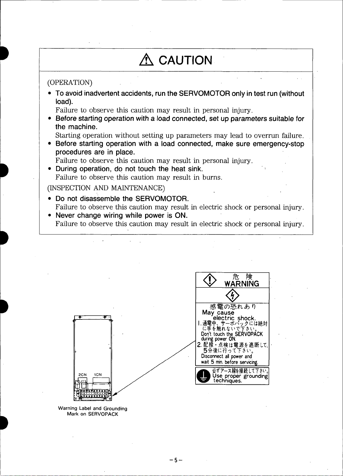
May cause
Don't touchthe SERV0PACK
during power ON.
_ 2._,_. ,_(_,_L'C,
WARNING
electric shock.
D
Disconnect all power and
wait 5 mJn.before serv_in_.
2CN _CN Usepropergrounding
__. -- _1 techniques.
Warning. Label and Grounding
Mark on SERVOPACK
-5-
Page 7
CONTENTS t
1. RATINGS AND SPECIFICATIONS 9 6.5 PROTECTIVECIRCUIT 42
1.1 RATINGS AND SPECIFICATIONS 6.6 LED INDICATION 43
OF M SERIES AC SERVOMOTORS 9 6.7 PRECAUTIONS FOR APPLECATION 43
1.2 RATINGS AND SPECIFICATIONS 6.8 PRECAUTIONS FOR OPERATION 43
OF F SERIES AC SERVOMOTORS 11
1.3 RATINGS AND SPECIFICATIONS
OF S SERIES AC SERVOMOTORS 13 7. INSTALLATION AND WIRING 47
1.4 RATINGS AND SPECIFICATIONS 7.1 RECEIVING 47
OF D SERIES AC SERVOMORORS 15
1.5 RATINGS AND SPECIFICATIONS 7.3 WIRING 48
OF SERVOPACK 17
6.9 APPLICATION 45
7.2 INSTALLATION 47
2, TYPE DESIGNATIOM 19 8. DIMENSIONS in mm (inches) 50
8.1 SERVOMOTOR: M SERIES 50
3. LIST OF STANDARD COMBINATION 21 8.2 SERVOMOTOR:F SERIES 52
4. CHARACTERISTICS 24 8.3 SERVOMOTOR: S SERIES 55 I
4.1 OVERLOAD CHARACTERISTICS 24
4.2 STARTING AND STOPPING TIME 24
4.3 ALLOWABLE FREQUENCY
OF OPERATION 24 9. TEST RUN 63
4.4 SERVOMOTOR FREQUENCY 25 9.1 CHECK ITEMES BEFORE TEST RUN 63
4.5 MOTOR SPEED--REFERENCE 9.2 TEST RUN PROCEDURES 63
INPUT CHARACTERISTICS 25
4.6 MOTOR MECHANICAL 10. ADJUSTMENT 64 dB
CHARACTERISTICS 25 10.1 SEI-IINGS AT THE TIME
5. CONFIGURATION 28 OFDELIVERY 64
5.1 CONNECTION DIAGRAM 28 TIME OF DELIVERY 68
5.2 INTERNAL BLOCK DIAGRAM 29 10.3 READJUSTMENT 68
5.3 EXTERNAL TERMINALS 31
5.4 CONNECTOR TERMINAL (1CN) 10.5 SWITCH SEI-rlNG 73
FOR INPUT/OUTPUT SIGNALS 31
5.5 CONNECTOR TERMINAL (2CN) FOR 11. INSPECTION AND MAINTENANCE 74 .._
OPTICAL ENCODER (PG) CONNECTION 34 11.1 AC SERVOMOTOR 74
8.4 SERVOMOTOR: D SERIES 59
8.5 SERVOPACK 60
8.6 PERIPHERAL EQUIPMENT 61
10.2 CHARACTERISTICS AT THE
10.4 ADJUSTMENT PROCEDURES 68
JB
I
/
I
6. OPERATION 36 11.2 SERVOPACK 75
6.1 POWER ON AND OFF 36 12. TROUBLESHOOTING GUIDE 76
6.2 SPEED REFERENCE 37 12.1 AC SERVOMOTOR 76
6.3 EXTERNAL CURRENT LIMIT REFERENCE
CIRCUIT [P-CL-81-C N-CL] 38
6.4 CONFIGURATION OF
INPUT/OUTPUT CIRCUIT 39
12.2 SERVOPACK 77
Page 8
D INDEX
Subject Chapter Section No. Page
A ADJUSTMENT ........................................................................................................................ ]0 ................................. 64
ADJUSTMENT PROCEDURES ................................................................................................ ]0 ......... ]0.4 ............... 68
ALLOWABLE FREQUENCY OF OPERATION ........................................................................ 4 ......... 4.3 ............... 24
Allowable Radial Load and Thrust Load ............................................................ .,.................... 4 ......... 4,6.2 ............... 26
APPLICATION ........................................................................................................................ 6 ......... 6.9 ............... 45
Auxiliary Input Circuit ............................................................................................................ 6 ......... 6.2.4 ............... 37
C CHARACTERISTICS ........................................................ :...................................................... 4 ................................. 24
CHARACTERISTICS AT THE TIME OF DELIVERY ............................................................ 10 ......... ]0.2 ............... 68
CHECK ITEMS BEFORE TEST RUN .................................................................................... 9 ......... 9,] ............... 63
CONFIGURATION .................................................................................................................. 5 ................................. 28
CONFIGURATION OF INPUT/OUTPUT CIRCUITS ................... :........................................... 6 ......... 6.4 ............... 39
CONNECTION DIAGRAM ...................................................................................................... 5 ......... 5.] ": ............ 28
Connection for Reverse Motor Running ................................................................. :.................. 6 ......... 6.9,1 ............... 45
Connector ]CN Layout and Connection of SERVOPACK ......................................................... 5 ......... 5.4.2 ............... 31
CONNECTOR TERMINAL (1CN) FOR INPUT/OUTPUT SIGNALS ....................... :............... 5 ......... 5.4 ............... S]
D CONNECTOR TERMINAL (2CN) FOR OPTICAL ENCODER (PG) CONNECTION ............... 5 ......... 5.5 ............... 34
D NSTALLATION AND WIRING ................................................................................ ............. 7 ................................. 47
Current Limit when Motor is Locked 6 ..... _"'6.3.3 ............... 38
D DIMENSIONS in mm (inches) ........................................................................... :....................... 8 ................................. 50
Direction of Rotation ............................................................................................................... 4 ......... 4.6.4 ............... 26
E Examples of Troubleshooting for Defective Wiring or Parts ]2 ......... 12.2.2 ............... 78
Examples of Troubleshooting for Incomplete Adjustment ....................................................... .-]2 ......... 12.2.3 ............... 78
EXTERNAL CURRENT LIMIT REFERENCE CIRCUIT ........................... _...; ......................... 6 ......... 6.3 ..,...... _...... 38
EXTERNAL TERMINALS ...................................................................................................... 5 ......... 5.3 ............... 3]
H Handling of Speed Reference Input Terminal ........................................................................... 6 ......... 6.2.3 ............... 37
High Voltage Line .................................................................................................................. 6 ......... 6.7.3 ............... 43
Impact Resistance ............................... •..................................................................................... 4 ......... 4.6.5 ............... 27
Input Circuit ................... :....................................................................................................... 6 ......... 6.4.] ............... 39
INSPECTION AND MAINTENANCE ....................................................................................... 11 ................................. 74
Inspection during Test Run ...................................................................................................... 9 ......... 9.2.3 ............... 63
NSTALLATION ..................................................................................................................... 7 -........ 7.2 ............... 47
NTERNAL BLOCK DIAGRAM 5 ......... 5.2 •.............. 29
L LED INDICATION 6 ......... 6.6 ,. .............. 43
LED Indication(7-segment) for Troubleshooting ........................................................................ 12 ......... 12,2.1 ............... 78
LIST OF STANDARD COMBINATION .................................................................................... 3 ................................. 21
Load inertia (JL) ..................................................................................................................... 6 ......... 6.7.2 ............... 43
M Mechanical Specifications (M, F, S and D series) ........................................... '.......................... 4 ......... 4.6.3 ............... 26
Mechanical Strength .......................................................................................................... ]....... 4 ......... 4.6.1 ............... 25
Method of giving External Current Limit Reference .................................................................. 6 ......... 6.3.1 ............... 38
MOTOR MECHANICAL CHARACTERISTICS ........................................................................ 4 ......... 4.6 ............... 25
MOTOR SPEED-REFERENCE INPUT CHARACTERISTICS ................................................... 4 ......... 4.5 ............... 25
N Noise Control ........................................................................................................................... 6 ......... 6.8.] ............... 43
O OPERATION ........................................................................................................................... 6 ................................. 38
Operation ..................................................................................................................... ............ 9 ......... 9.2.2 ............... 63
Optical Enc()der (PG) Output Circuit ........................................................................................ 6 ......... 6.4.3 ............... 40
Output Circuit ...................................................................................................... _ .................... 6 ......... 6.4.2 ............... 39
Overhanging Loads .................................................................................................................. 6 ......... 6.7.1 ............... 43
OVERLOAD CHARACTERISTICS ....................................................................................... :" 4 ......... 4.1 ........ ....... 24
P Power Line Protection ............................................................................................................ 6 ......... 6.8.2 ............... 45
D Power Loss .............................................................................................................................. 7 ......... 7.3.3 ............... 49
POWER ON AND OFF ............................................................................................................ 6 ......... 6.1 .................. 36
-7-
Page 9
Subject Chapter SectionNo. Page
P PRECAUTIONS FOR APPLICATION .................................................................................... 6 ......... 6.7 ............... 43
PRECAUTIONS OF OPERATION .......................................................................................... 6 ......... 6.8 ............... 43
Preparation of Operation ......................................................................................................... 9 ......... 9.2.] ............... 63
PROTECTIVE CIRCUIT ......................................................................................................... 6 ......... 6,5 ............... 42
PERIPHERAL EQUIPMENT ................................................................................................... 8 ......... 8.6 ............... 61
R Rated Current and Cable Size ................................................................................................... 7 ......... 7.3.] ............... 48
RATINGS AND SPECIFICATIONS .......................................................................................... ] ................................. 9
RATINGS AND SPECIFICATIONS OF D SERIES AC SERVOMOTORS ................................. 1 ......... 1.4 ............... _5
RATINGS AND SPECIFICATIONS OF F SERIES AC SERVOMOTORS ................................. 1 ......... 1.2 ............... 11
RATINGS AND SPECIFICATIONS OF M SERIES AC SERVOMOTORS ................................. I ......... ].] ............... 9
RATINGS AND SPECIFICATIONS OF S SERIES AC SERVOMOTORS ................................. ] ......... 1.3 ............... 13
RATINGS AND SPECIFICATIONS OF SERVOPACK ............................................................ I ......... 1.5 ............... 17
Ratings of D Series AC SERVOMOTORS ................................................................................. ] ......... ].4.1 ............... 15
Ratings of F Series AC SERVOMOTORS ................................................................................. I ......... 1.2.1 ............... ]]
Ratings of M Series AC SERVOMOTORS ................................................................................. I ......... 1.1.1 ............... 9
Ratings of S Series AC SERVOMOTORS ................................................................................. I ......... 1.3.1 ............... ]3
READJUSTMENT .................................................................................................................. 10 ......... 10.3 ............... 68
RECEIVING ................................... " ....................................................................................... 7 ......... 7.] ............... 47
S SERVOMOTOR DIMENSIONS: D SERIES .............................................................................. 8 ......... 8.4 ............... 59
SERVOMOTOR DIMENSIONS: F SERIES .............................................................................. 8 ......... 8.2 ............... 52
SERVOMOTOR DIMENSIONS: M SERIES ........................................................................... 8 ......... 8.1 ............... 50
SERVOMOTOR DIMENSIONS: S SERIES .............................................................................. 8 ......... 8.3 ............... 55
SERVOMOTOR FREQUENCY ................................................................................................ 4 ......... 4.4 ............... 25
SERVOPACK ........................................................................................................................... 1] ......... 11.2.................. 75
SERVOPACK Connector (2CN) Terminal Layout and Connection .......................................... 5 ......... 5.5.2 ............... 34
SERVOPACK DIMENSIONS ................................................................................................... 8 ......... 8.5 ............... 60
Set Voltage and Current Limit Values .................................................................................... 6 ......... 6.3.2 ............... 38
SETTINGS AT THE TIME OF DELIVERY ........................................................................... ]0 ......... ]0.1 ............... 64
Specifications of Applicable Receptacles .................................................................................... 5 ......... 5.4.1 ............... 31
Specifications of Applicable Receptacles and Cables .................................................................. 5 ......... 5.5.1 ............... 34
Speed and Torque Measurement ................................................................................................ 6 ......... 6.9.2 ............... 46
SPEED REFERENCE ............................................................................................................... 6 ......... 6.2 ............... 37
Speed Reference Circuit ............................................................................................................ 6 ......... 6.2.1 ............... 37
STARTING AND STOPPING TIME ....................................................................................... 4 ......... 4.2 ............... 24
Stop Reference Circuit ............................................................................................................... 6 ......... 6.2.2 ............... 37
SWITCH SETTI NG .................................................................................................................. 10 ......... 10.5 ............... 73
T TEST RUN .............................................................................................................................. 9 ................................. 63
TEST RUN PROCEDURES ...................................................................................................... 9 ......... 9.2 ............... 63
Torque-Speed Characteristics of D Series AC SERVOMOTORS ................................................ ] ......... ].4.2 ............... 16
Torque-Speed Characteristics of F Series AC SERVOMOTORS ................................................ ] ......... ].2.2 ............... ]2
Torque-Speed Characteristics of M Series AC SERVOMOTORS ................................................ ] ......... 1.1.2 ............... ]0
Torque-Speed Characteristics of S Series AC SERVOMOTORS ................................................... 1 ......... ].3.2 ............... ]4
TROUBLESHOOTING GUIDE ................................................................................................ ]2 ................................. 76
TYPE DESIGNATION ............................................................................................................ 2 ................................. ]9
V Vibration Class ........................................................................................................................ 4 ......... 4.6.7 ............... 27
Vibration Resistance ............................................................................................................... 4 ......... 4.6.6 ............... 27
W WIRING ................................................................................................................................. 7 ......... 7.3 ............... 48
Wiring Precautions .................................................................................................................. 7 ......... 7.3.2 ............... 49
INDEX (Cont'd) e
II
Page 10
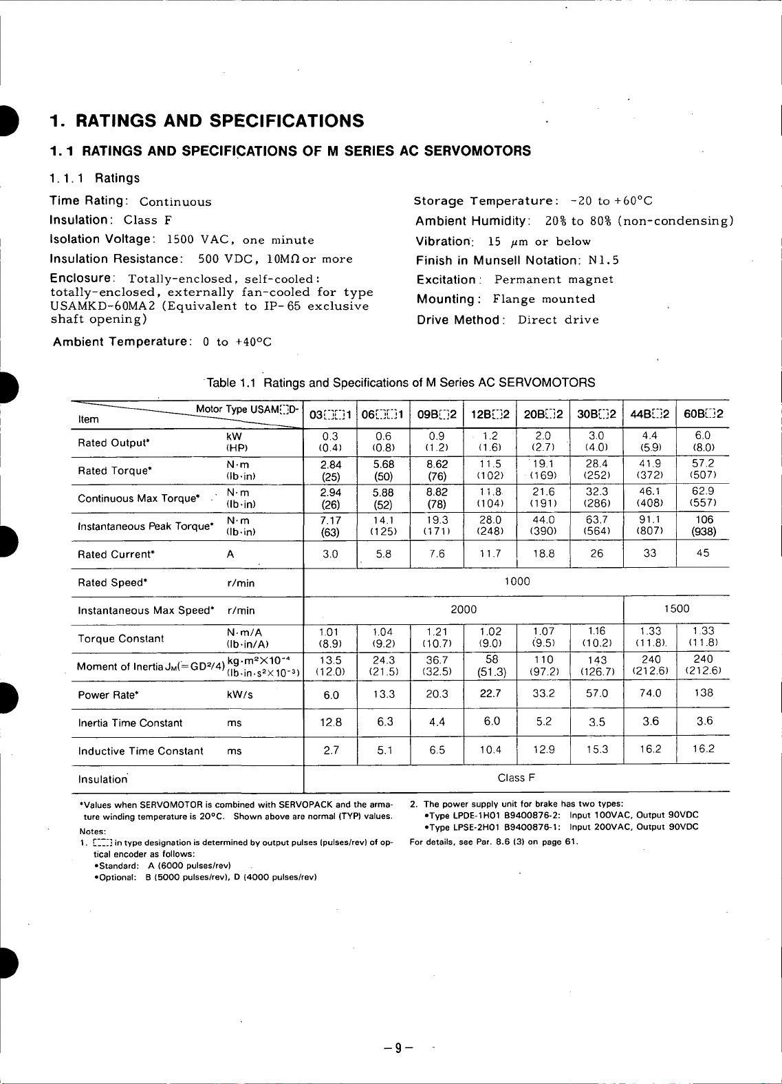
D 1. RATINGS AND SPECIFICATIONS
1.1 RATINGS AND SPECIFICATIONS OF M SERIES AC SERVOMOTORS
1.1.1 Ratings
Time Rating: Continuous Storage Temperature: -20 to +60°C
Insulation: Class F Ambient Humidity: 20%to 80% (non-condensing)
Isolation Voltage: 1500 VAC, one minute Vibration: 15 ILm or below
Insulation Resistance: 500 VDC, 10M_or more Finish in Munsell Notation: N].5
Enclosure: Totally-enclosed, self-cooled : Excitation : Permanent magnet
totally-enclosed, externally fan-cooled for type Mounting" Flange mounted
USAMKD-60MA2 (Equivalent to IP-65 exclusive
shaft opening) Drive Method: Direct drive
Ambient Temperature: 0 to +40°C
Table 1.1 Ratings and Specifications of M Series AC SERVOMOTORS
D
_A ;-I - 03 1 '06 44B[]2
Ite _ -
Rated Output* (HP) (0.4) I (0.8) (1.2) (1.6) (2.7) ' (4.0) (8.0)
Rated Torque* (Ib,in) (25) I (50) (76) (102) (169) (252) (372) (507)
Continuous Max Torque* (Ib,in) (26) I (52) (78) (104) (191) (286) (408) I (557)
kW 0.3 L 0.6 0.9 1.2 2.0 3.0 4.._) 6.0
N-m 2.84 I 5.68 8.62 11.5 19.1 28.4 41.9 57.2
, N-m 2.94 I 5.88 8.82 11.8 21.6 32.3 46.1 I 62.9
N.m 7.17 14.1 19.3 28.0 44.0 63.7 91.1 [ 106
M,.,D ;-_r-;...... r-_r_l...... 09Br-]2 12B[-]2 20B[-]2 30B[]]2 60B[_-]2
D Instantaneous Peak Torque* (Ib,in) (63) (125) (171) (248) (390) (564) (807) (938)
D Power Rate* kW/s 6.0 13.3 20.3 22.7 33.2 57.0 74.0 138
Rated Current* A 3.0 I. 5.8 7.6 11.7 18.8 26 33 45
Rated Speed* r/rain 1000
Instantaneous Max Speed* r/rain 2000 1500
Torque Constant (Ib.in/A) (8.9) (9.2) (10.7) (9.0) (9.5) (10.2) (11.8). (11.8)
Moment of Inertia JM('----GD2/4) kg'm2XlO'" 13.5 24.3 36.7 58 110 143 240 240
Inertia Time Constant ms 12.8 6.3 4.4 6.0 5.2 3.5 3.6 3.6
Inductive Time Constant ms 2.7 5.1 6.5 10.4 12.9 15.3 16.2 16.2
Insulation ClassF
*Values when SERVOMOTOR is combined with SERVOPACK and the arma- 2, The power supply unit for brake has two types:
ture winding temperature is 20°C. Shown above are normal (TYP) values. ,Type LPDE-1H01 B9400876-2: Input IOOVAC, Output 90VDC
Notes: ,,Type LPSE-2H01 B9400876-1: Input 20OVAC, Output 9OVDC
1. [---] in type designation is determined by output pulses (pulses/rev) of op- For details, see Par. 8.6 (3) on page 61.
tical encoder as follows:
oStandard: A (6000 pulses/rev)
oOptional: B (5000 pulses/rev), D (4000 pulses/rev)
N.m/A 1.01 1.04 1.21 1.02 1.07 1.16 1.33 1.33
(Ib.in.s2× 10-3 ) (12.0) (21.5) (32.5) (51.3) (97.2) (126.7) (212,6) (212.6)
-9-
Page 11

1.1.2 Torque-Speed Characteristics g
• TYPE USAMED-03[_-] • TYPE USAMED-20B
,,,ll
E2000 - +.... "_2°°°i ,+ ....... _ ---:_2 '=_ T: -+---,
E '-_'! ' _.isoo _ISOO _ isoo ,
;500 _ 8 "'
"E20001 _,_ _,_ 2 20001 ,, +._,
,ooo__ _ti __1ooo _ / Ai_ LI '_ _,
0 2 4 6 I; 20 40 60 0 10 20 30 40 0 100 200 300 400
RMS TORQUE (N-m) RMS TORQUE (Ib.in) RMS TORQUE (N.m) RMS TORQUE (Ib.in)
• TYPE USAMED-06_] • TYPE USAMED-30B
2ooo_ _2oooI............. 12ooo..................,,-._. _2ooo
++oo+,++,+oop ++oo++
+00_ 2+, 210, +oo_l
1101 +°OOOlBI1 ++,ooo[A!I +++°°°I
0 3 6 9 12 _ 2's8_7_;_0'_5 0 20 ;0 60 0 200 _00 600
RMS TORQUE (N-m) RMS TORQUE (Ib.in) RMS TORQUE (N.m) RMS TORQUE (Ib.in) /
• TYPEUSAMED-09B • TYPEUSAMED-44B
" • _ _-+,....... _1_ooI ,_, -..,._._
4
- __o°°r_---_ __°°°I __ooo_
_1800 r _ _ + 1500F ",_ _l _ 15001 ,++.#_ _ _ 1500_
,9, m,ooo ,,11oooi-"\'_'_ _,1ooo
• [] i I I] + + I++l:11
0 4 8 12 16 0 50 100 150 0 20 40 60 80 0 200 400 600 8001000
RMS TORQUE (N +m) RMS TORQUE (Ib.in) RMS TORQUE (N .m) RMS TORQUE (Ib.in) 4
• TYPEUSAMED-12B • TYPEUSAMKD-60B
2800_ _2000_ _2000r _ ._2°°°I
._2ooo _ _,+oo
_1500F "_+" _ _ 1500r \:5_ _"'_ ....
_1000 _1000 + 1000P ":"/'_% _1000
° t:',x,+,H° i \+ l ,A,.,I,B_
0 10 20 50 100 150 200 250 0 2_5 80 75 100 0 200 400 600 8001000
RMS TORQUE (N.m) RMS TORQUE (Ib-in) RMS TORQUE (N.m) RMS TORQUE (Ib-in)
28001 2_°°/ t _2_°°/
CO A ' ;
A: CONTINUOUS DUTY ZONE
B: INTERMITTENT DUTY ZONE
POWER SUPPLY: 200V i
i
I
-10-
Page 12
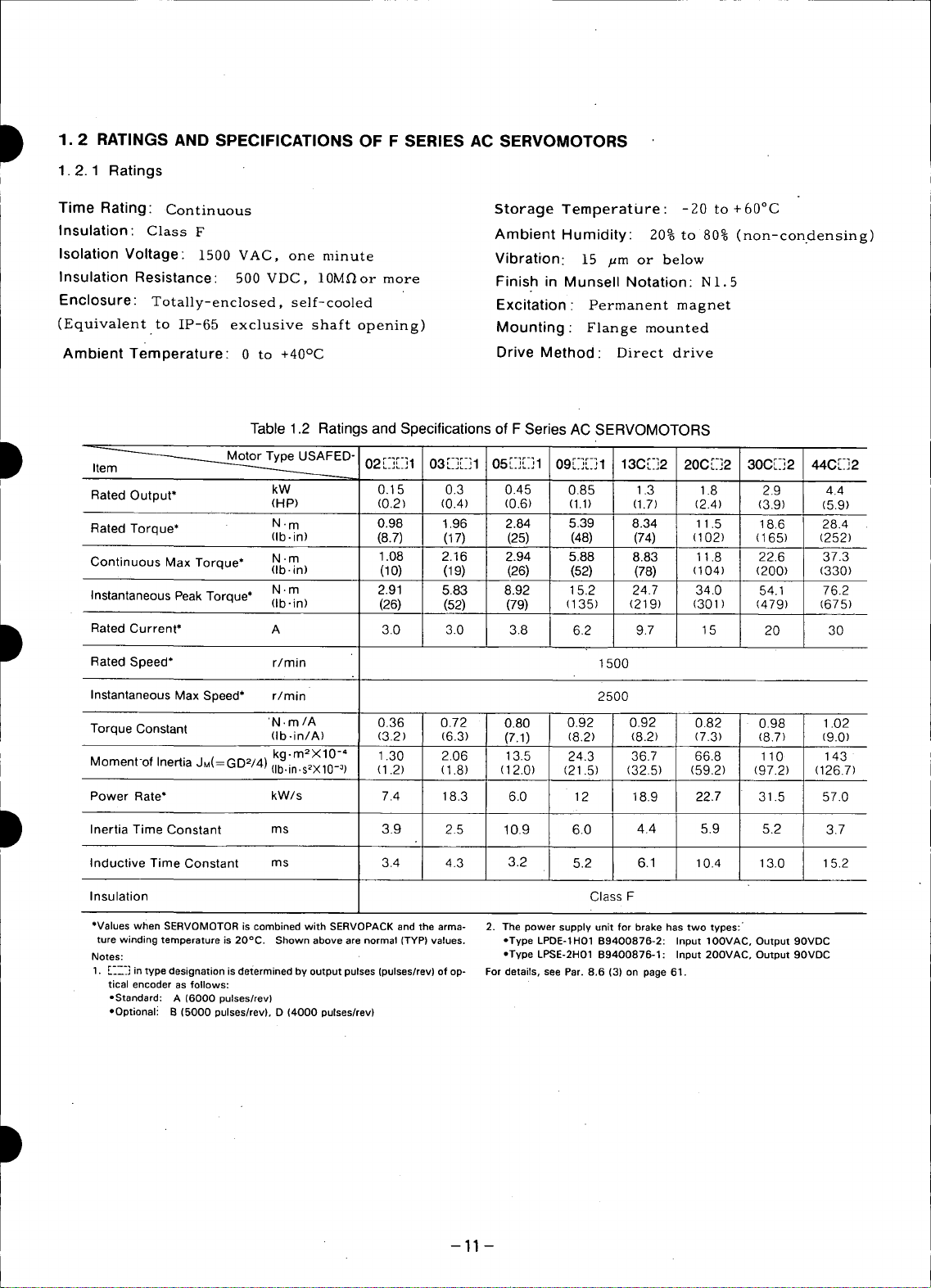
D 1.2 RATINGS AND SPECIFICATIONS OF F SERIES AC SERVOMOTORS
1.2.1 Ratings
Time Rating: Continuous Storage Temperature : -20 to + 60°C
Insulation: Class F Ambient Humidity: 20% to 80% (non-con.densing)
Isolation Voltage: 1500 VAC, one minute Vibration: 15 ,_m or be]ow
Insulation Resistance: 500 VDC, 10M_or more Finish in Munsell Notation: NI.5
Enclosure: Totally-enclosed, self-cooled Excitation : Permanent magnet
(Equivalent to IP-65 exclusive shaft opening) Mounting: Flange mounted
Ambient Temperature: 0 to +40°C Drive Method: Direct drive
Table 1.2 Ratings and Specifications of F Series AC SERVOMOTORS
D _ D" r-_r-il r-lr-i r-lr-_ 09_-'_"1 130_-2
02 ...... I 03 ...... 1 r _r-_ r-i
05 ...... 1 20C [.-]2 30C[-]2 _44C[]2
kW 0.1 5 I 0.3 0.45 0.85 1.3 1.8 2.9 I 4.4
Rated Output* (HP) (0.2) I (0.4) (0.6) (1.1) (1.7) (2.4) (3.9) I (5.9)
Rated Torque* N-m 0.98 I 1.96 2.84 ' 5.39 8.34 11.5 18.6 t 28.4
Continuous Max Torque* N .m 1.08 I 2.16 2.94 5.88 8.83 11.8 22.6 [ 37.3
Instantaneous Peak Torque* N. m 2.91 I 5.83 8.92 15.2 24.7 34.0 h4 1 I 76.2
(Ib.in) (8.7) I (17) (25) : (48) (74) (102) (165) I (252)
(Ib.in) (10) I (19) (26) (52) (78) (104) (200) I (330)
(Ib-in) (26) I (52) (79) (135) (21 9) (301) (47_) I (675)
I
i
i
D Rated Current* A 3.0 I 3.0 3.8 6.2 9.7 15 20 I 30
Rated Speed* r/min 1500
Instantaneous Max Speed* r/rain 2500
Torque Constant 'N. m/A 0.36 0.72 0.80 0.92 0.92 0.82 0.98 1.02
(Ib.in/A) (3.2) (6.3) (7.1) (8.2) (8.2) (7.3) (8.7) (9.0)
kg-m2X10 -" 1.30 2.06 13.5 24.3 36.7 66.8 110 143
Moment-of Inertia JM(= GD2/4) (ib.in.s2X10_3) (1.2) (1.8) (12.0) (21.5) (32.5) (59.2) (97.2) (126.7)
Power Rate* kW/s 7.4 18.3 6.0 12 18.9 22.7 31.5 57.0
4.4
5.9
D Inertia Time Constant ms 3.9 2.5 10.9 6.0 5.2 3.7
Inductive Time Constant ms 3.4 4.3 3.2 5.2 6.1 10.4 13.0 15.2
Insulation ClassF
*Valueswhen SERVOMOTORis combinedwith SERVOPACKandthe arma- 2. The power supply unit for brake hastwo types:
ture windingtemperatureis 20°C. Shown abovearenormal(TYP)values, oType LPDE-1H01B9400876-2: Input IOOVAC,Output 90VDC
Notes: *TypeLPSE-2H01B9400876-1: Input2OOVAC,Output90VDC
1, [-__-_]in type designationis determinedby output pulses(pulses/rev)of op- For details, seePar.8.6 (3) on page61.
tical encoder as follows:
-Standard: A (6000 pulses/rev)
oOptionali B (5000 pulses/rev),D (4000 pulses/rev)
--11 --
Page 13
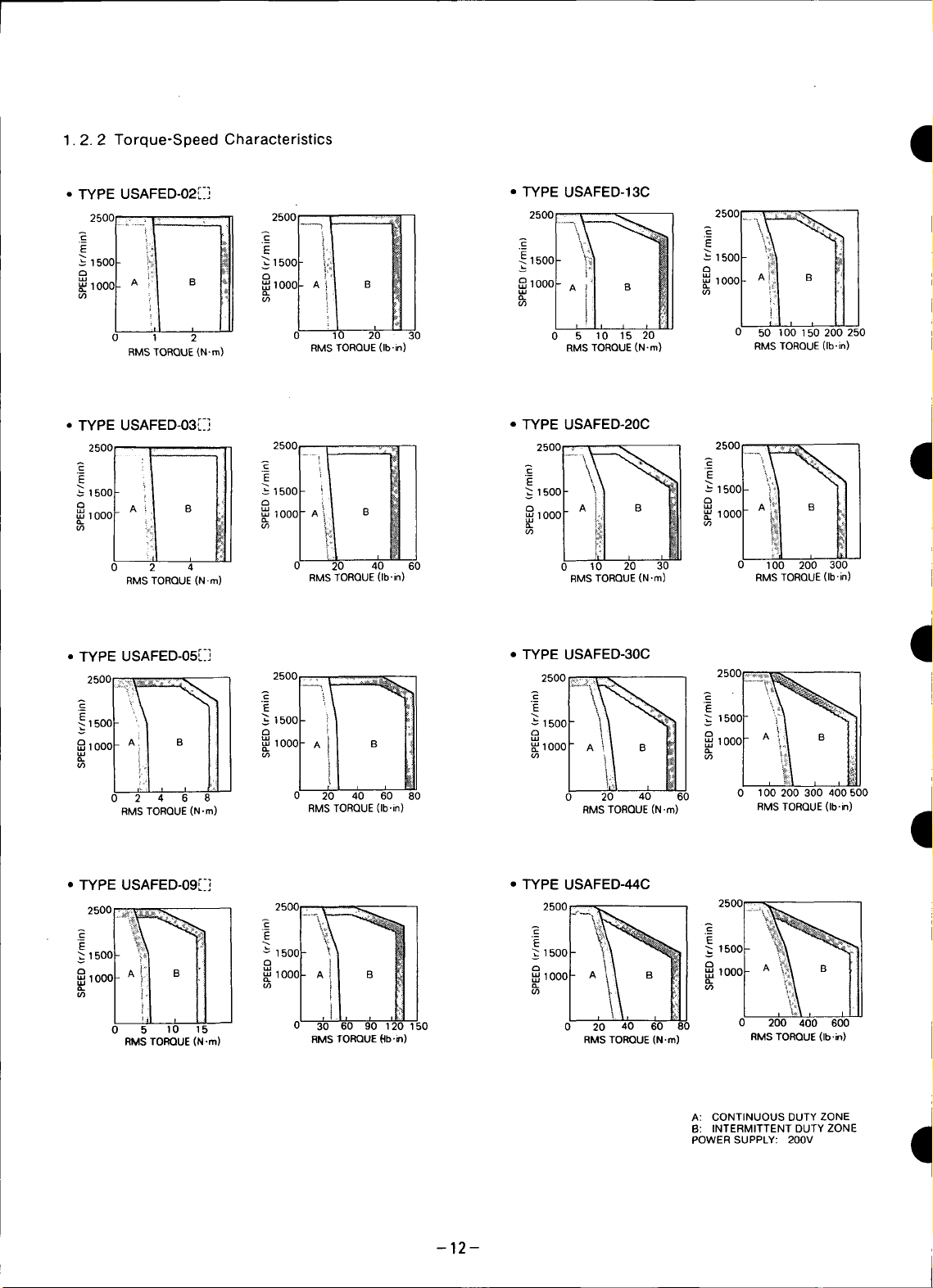
1.2.2 Torque-Speed Characteristics I
• TYPEUSAFED-02[_] • TYPEUSAFED-13C
25oo_ ...... _ _, -_
(_)1000_ __)1ooo_ _/!l MI" /)1_,II1
0 ,--2 0 10 20 30 0 _ ;0 _5_0 0 5010b1_0200250
RMS TORQUE{N,m) RMS TORQUE (Ib-in) RMS TORQUE(N.m} RMS TORQUE(Ibgn)
• TYPEUSAFED-03[_] • TYPEUSAFED-20C
1500 "_ 1500 _1500 " _ 1500l \_% I t
,all
,,a, rA!)t B _t _ O [A \\ _1 8 A! ;_
_iooo _ _,_l _/" _ 'Ill
2500..... I'l 2500, ........ 25°°I,_--_\ I 2500....,.
!i t000 A i "u_' 1000_ l'ill B_l _ 10001- _1 B _!1 /
,iil _!t • _, o, /_!1
0 2 4 20 40 60 0 ,0 20 30 0 100 200 300
RMS TORQUE(N.m) RMS TORQUE(Ib-in) RMS TORQUE(N.m) RMS TORQUE(Ib'in)
dl
• TYPE USAFED-05[:] • TYPE USAFED-30C
E1500 _1500 i ,500
,oooLAi _ 8,ooor__:,I_ II
° il fl
0 2 4 6 8 0 20 40 60 80 0 20 40 60 0 100 200 300 400 500
RMS TORQUE(N.m) RMS TORQUE(Ib.in) RMSTORQUE (N .m) RMS TORQUE(Ib-in)
I
• TYPEUSAFED-09r_] • TYPEUSAFED-44C
1500 "_ 1500
,ooog,l:IB I:I 100o
if) _i"
""'" l'iC""°°°[!i
2500_ _ J 2500 "........... ,- _':_ _11...... i2500-'"_i_ I 2500 __...... ,1.o Ooi.l,i ,,
0 5 10 15 0 30' 60 90 120 150 0 20 40 60 80 0 200 400 600
RMS TORQUE(N-m) RMS TORQUE(-Ib.rl) RMS TORQUE (N.m) RMSTORQUE(Ib.in)
-12-
A: CONTINUOUS DUTY ZONE
B: INTERMITTENT DUTY ZONE
POWER SUPPLY: 200V
Page 14
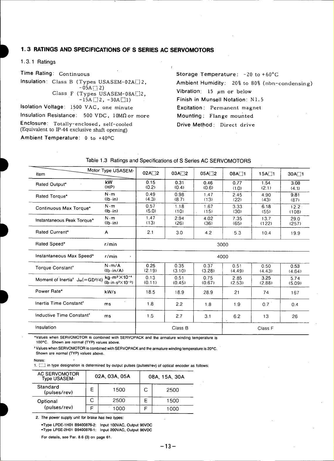
1.3 RATINGS AND SPECIFICATIONS OF S SERIES AC SERVOMOTORS
1.3.1 Ratings
Time Rating Continuous Storage Temperature: -20 to +60°C
Insulation" Class B (Types USASEM-02A[-] 2, Ambient Humidity: 20% to 80% (nt)n-condensing)
- 05A!_] 2)
Class F (Types USASEM-08A[-]2, Vibration. 15 /_m or below
-15At-12, -30A[-]1) Finish in Munsell Notation: NI.5
Isolation Voltage" 1500 VAC, one minute Excitation: Permanent magnet
Insulation Resistance: 500 VDC, 10Mf_or more Mounting" Flange mounted
Enclosure: Totally-enclosed, self-cooled Drive Method Direct drive
(Equivalent to IP-44 exclusive shaft opening)
Ambient Temperature" 0 to +40°C
D Table 1.3 Ratings and Specifications of S Series AC SERVOMOTORS
_EM 02A[-_]2 03A[-]2 05A[_]2 08A[-]1 15A[-]1 30A[[]1
Rated Output* kW 0.15 0.31 0.46 0.77 1.54 3.08
Rated Torque* N. m 0.49 0.98 1.47 2.45 4.90 9.81
Continuous Max Torque* N.m 0.57 I .I 8 1.67 3.33 6.18 12.2
(HP) (0.2) (0.4) (0.8) (1.0) (2.1) (4.1)
(lb. in) (4.3) (8.7) (13) (22) (43) (87)
(lb.in) (5.0) (I 0) (15) (30) (55) (108)
N.m 1.47 2.94 4.02 7.35 13.7 29.0
Instantaneous Peak Torque" (Ib.in) (13) (26) (36) (65) (122) (257)
/
D Rated Current* A 2.1 3.0 4.2 5.3 10.4 19.9
Rated Speed* r/min 3000
Instantaneous Max Speed* r/min 4000
Torque Constant* N. m/A 0.25 0.35 0.37 0.51 0.50 0.53
(Ib-in/A) (2.19) (3.10) (3.28) (4.49) (4.43) (4.64)
" kg.m2X10 "4 0.13 0.51 0.75 2.85 3.25 5.74
Moment of Inertia t JM(=GD2/4) (ib.in.s2×10_3) (0.11 ) (0.45) (0.67) (2.53) (2.88) (5.09)
D Power Rate* kW/s 18.5 18.9 28.9 21 74 167
Inertia Time Constant t ms 1.8 2.2 1.8 1.9 0.7 " 0.4
InductiveTime Constant_ ms 1.5 2.7 3.1 6.2 13 26
Insulation ClassB ClassF
*values whenSERVOMOTORis combinedwith SERVOPACKand the armaturewinding temperatureis
100°C. Shownare normal(TYP)valuesabove.
tValueswhenSERVOMOTORiscombinedwith SERVOPACKandthearmaturewindingtemperatureis 20°C.
Shownare normal(TYP)valuesabove.
Notes:
1. [_-] in type designationis determinedby outputpulses (pulses/rev)ofoptical encoderas follows:
AC SERVOMOTOR
Type USASEM- 02A, 03A, 05A 08A, 1 5A, 30A
Standard
(pulses/rev) E 1 500 C 2500
Optional C 2500 E 1500
D (pulses/rev) F 1000 F 1000
2. The powersupptyunitfor brakehas twotypes:
=TypeLPDE-1H01B9400876-2: Input 100VAC,Output90VDC
*TypeLPSE-2H01B9400876-1: Input200VAC,Output90VDC
Fordetails,seePar.8.6(3) onpage61.
--13--
Page 15
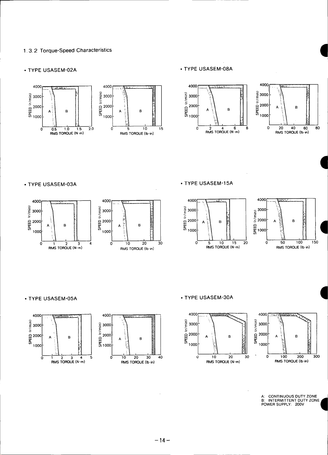
1.3.2 Torque-Speed Characteristics I
• TYPE USASEM-02A •TYPE USASEM-08A
,ooo.....,....... _'°°°t__ ,ooo_ ,oooai._,_....._t
&2ooo__ t_ , _2ooo__ _ H i=°°°r,_\ _ III _:=°°°r*ik _JJi
"_ '°°°Ii/ H
0 0.5 1.0 1.5 2.0 0 5 10 15 0 2 4 6 8 0 20 40 60 80
RMS TORQUE(N-m) RMS TORQUE (Ib.in) RMS TORQUE(N-m) RMS TORQUE (Ib.in)
• TYPEUSASEM-03A ,TYPE USASEM-15A
:_°°°r,/ Li / _°°°r:t _ I _oool-_ L,J _3°°°F'_i_ [:i]
,14i,l°W , ,
0 1 2 3 4 0 10 20 30 0 5 10 15 20 0 50 100 150
RMS TORQUE(N.m) RMS TORQUE(Ib.in) RMS TORQUE (N.m) RMS TORQUE(Ib-in)
•TYPEUSASEM°05A • TYPEUSASEM-30A
t/, []/ •"_ _" 3000I ""/ _!] "_"2000_ A i/ B I!]
(/_1000 _) 1000 i_ (,O1000 (,_ i:_
. ,_.I,, _ . /:I , ,_I, . _,;i_I, M, L _:.:_,iI, _Ii
0 1 2 3 4 5 0 10 20 30 40 0 10 20 30 0 100 200 300
RMS TORQUE(N.m) RMS TORQUE(Ib-in) RMSTORQUE(N.m) RMS TORQUE(Ib.m)
/ ,oooI i:/-,II ,ooo ,ooo, _',_ , ,i, , , / ;,/ , I,t
2oooF ',I _1 I _2000rA _,/ B l;Ii 8
A: CONTINUOUS DUTY ZONE
B: INTERMITTENT DUTY ZONE,_
POWER SUPPLY: 200V
q
-14-
Page 16
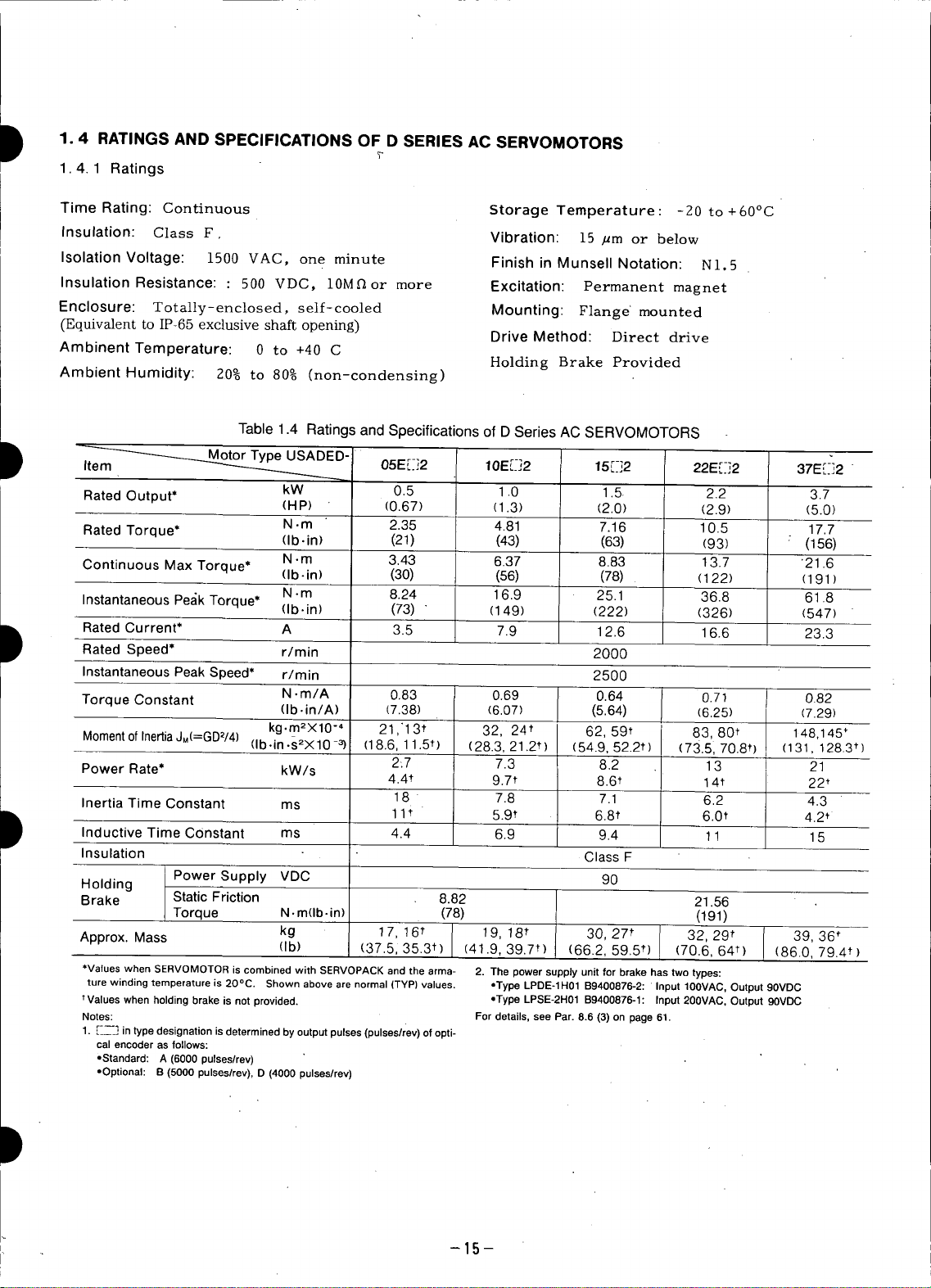
1.4 RATINGS AND SPECIFICATIONS OF D SERIES AC SERVOMOTORS
1.4.1 Ratings
Time Rating: Continuous Storage Temperature : -20 to + 60°C
Insulation: Class F. Vibration: 15 /_m or below
Isolation Voltage: 1500 VAC, one minute Finish in MunsellNotation: N1.5
Insulation Resistance: : 500 VDC, 10Mflor more Excitation: Permanent magnet
Enclosure: Totally-enclosed, self-cooled Mounting: Flange' mounted
(Equivalent to IP-65 exclusive shaft opening) Drive Method: Direct drive
Ambinent Temperature: 0 to +40 C
Ambient Humidity: 20% to 80% (non-condensing)
Table 1.4 Ratings and Specifications of D Series AC SERVOMOTORS
Y
Holding Brake Provided
I Motor Type USADED-I
i Rated Current* A 3.5 7.9 12.6 16.6 23.3
D Inductive Time Constant ms 6.9 9.4 11 15
Item -- 05E_-,:2 10E[_-]2 15r-]2 22Er-]2 37E[-_2
kW 0.5 1.0 1.5 2.2 3.7
Rated Output* (HP) (0.67) (1.3) (2.0) (2.9) (5.0)
RatedTorque* N.m 2.35 4.81 7.16 10.5 17.7
Continuous Max Torque* (Ib-in) (30) (56) (78) (122) (191 )
Instantaneous Pe_ikTorque* (Ib.in) (73) " (149) (222) (326) (547)
Rated Speed* r/min 2000
Instantaneous Peak Speed* r/min 2500 :
Torque Constant N .m/A 0.83 0.69 0.64 0.71 0.82
M°ment °f Inertia JM(=GD_/4) (Ib.in.s2X10 -3) (18.6, 11.5t) (28.3, 21.2,) (54.9, 52.2t) (73.51 70.8t) (131, 128.3 t)
Power Rate* kW/s
Inertia Time Constant ms 11_ 5.9t 6.8, 6.0* 4.2_
Insulation ClassF
Holding
Brake Static Friction 8.82 21.56
PowerSupply VDC 90
Torque N. m(Ib-in) (78) (191)
(Ib.in) (21) (43) (63) (93) :(156)
N. m 3.43 6.37 8.83 13.7 '21.6
N. m 8.24 16.9 25.1 36.8 61.8
(lb. in/A) (7.38) (6.07) (5.64) (6.25) (7.29)
kg.m2X10 "" 21,'13, 32, 24t 62, 59t 83, 80t 148,145'
2-.7 7.3 8.2 13 21
4.4t 9.7* 8.6t 14t 22t
18" 7.8 7.1 6.2 4.3
4.4
Approx. Mass (Ib) (37.5, 35.3t) (41.9, 39.7t1 (66.2, 59.5*) (70.6, 64*) (86.0, 79.4t)
*ValueswhenSERVOMOTORiscombinedwithSERVOPACKandthearma- 2. Thepowersupplyunitforbrakehastwotypes:
turewindingtemperatureis20°C. Shownabovearenormal(TYPIvalues, oTypeLPDE-1H01B9400876-2:Input100VAC,Output90VDC
tValueswhenholdingbrakeis notprovided. ,,TypeLPSE-2H01B9400876-1:Input200VAC,Output90VDC
Notes: Fordetails,seePar.8.6(3)onpage61.
1.['__--.]intypedesignationisdeterminedbyoutputpulses(pulsesliev)ofopti-
cal encoder as follows:
-Standard:A (6000pulses/rev)
,Optional: B(5000pulseslrev),O(4000pulses/rev)
kg 17, 16' l 19,18' 30,27' 32,29' [ 39,36'
--15--
Page 17
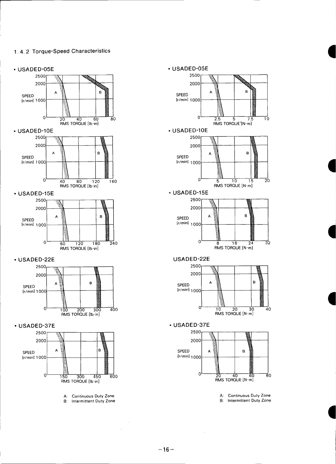
1.4.2 Torque-Speed Characteristics
• USADED-05E • USADED-05E
2000 : _ 2000
SPEED SPEED I!
oo. oo
[r/mini
1000 [r/min} 1000 1
0 20 40 60 80 2.5 5 7.5 10
RMSTORQUE[Ib-in] RMSTORQUE°[N"m]
• USADED-10E • USADED-10E
2500:_ _ 2500_%1 & I
SPEED ii SPEED
[r/mini 1000 [r/mini 1000 I
0' 40 80 120 160 0 5 10 15 20
RMS TORQUE [Ib'in] RMS TORQUE IN'm]
• USADED-15E • USADED-15E
2500_i_
25°°1A'_ BY_ 2000_il
SPEED i_ii SPEED
[r/minl 1000 ' [r/rain] 1000 _]
20oo _'1 _ A B i
0 60 120 180 240 0 8 36 24 32
RMSTORQUE[Ib'in] RMSTORQUE[N'm]
• USADED-22E USADED-22E
2500 :_, _ 2500 _
I
2ooc 2000 I
SPEED _ [r/mini 1000
[r/mini 100C
100 200 300 400 10 20 30 40
RMSTORQUE[Ib'in] RMSTORQUE[N"m]
• USADED-37E • USADED-37E
2500_ _ 2500_:,_
2000 '_!i_ 2000
SPEED A B SPEED A B
,r,m, ,,000 'r''o' 000
0 150 300 450 600 20 40 60 80
RMSTORQUE[Ib'in] RMSTORQUE[N-m]
A: Continuous Duty Zone A: Continuous Duty Zone
B: Intermittent Duty Zone B: Intermittent Duty Zone
B SPEED A _i,_ B i
I
-16-
I
Page 18
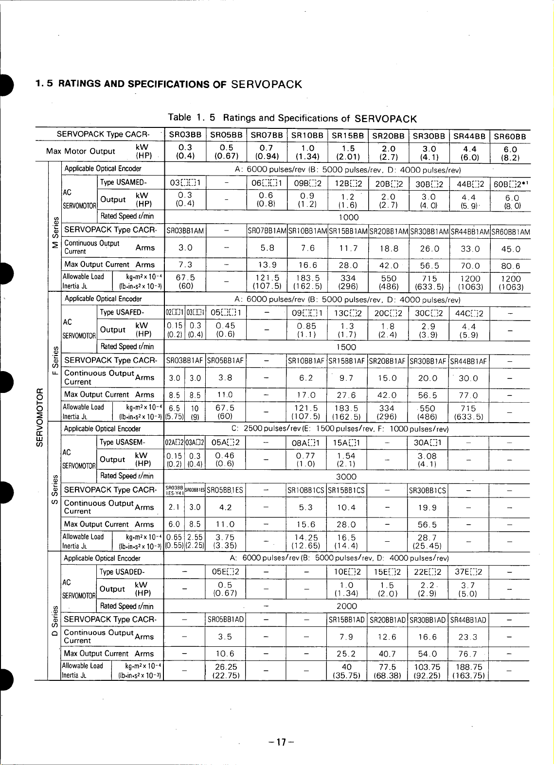
D 1.5 RATINGS AND SPECIFICATIONS OF SERVOPACK
Table 1. 5 Ratings and Specifications of SERVOPACK
SERVOPACKTypeCACR- SRO3BB SRO5BB SRO7BB SRIOBB SR15BB SR2OBB SR3OBB SR44BB SR6OB8
Max Motor Output kW 0.3 0.5 0.7 1.0 1.5 2.0 3.0 4.4 6.0
ApplicableOpticalEncoder A: 6000 pulses/rev (B: 5000 pulses/rev, D: 4000 pulses/rev)
Type USAMED- rqrq
AC
SERVOMOTOFOutput kW 0.3 0.6 0.9 1.2 2.0 3.0 4.4 6.0
_, RatedSpeedr/rain 1000
_ SERVOPACK Type CACR- SRO3B81AM - SRO7BB1AM SRIOBB1AM SR15BB1AM SR20B81AM SR3OBB1AM SR44BB1AM SR60B81AM
03
Continuous Output
Current " Arms 3.0 - 5.8 7.6 11.7 18.8 26.0 33.0 45.0
(HP) (0.4) (0.67) (0.94) (1.34) (2.01) (2.7) (4.1) (6.0) (8.2)
03 ...... 1 - 06[_][-]1 09B[_-]2 12B[-]2 20B[-]2 30B[.-]2 44B[_-]2 60B[_]2"
(HP) (0.4) (0.8) (1.2) (1.6) (2.7) (4.O) (5.9)- (8.O)
D Max Output Current Arms 7.3 - 13.9 16.6 28.0 42.0 56.5 70.0 80.6
D u_ Continuous OutpUtArms
AllowableLoad kg.m2x10-4 67.5 _ 121.5 183.5 334 550 715 1200 1200
InertiaJL (Ib.in.s2x10-3) (60) (107.5) (162.5) (296) (486) (633.5) (1063) (1063)
ApplicableOptical Encoder A: 6000 pulses/rev (B: 5000 pulses/rev, D 4000 pulses/rev)
Type USAFED- 32[][-,"103[]L_1 t-;r-;
AC
SERVOMOTOROutput kW 10.15 0.3 0.45 _ 0.85 1.3 1.8 2.9 4.4
RatedSpeedr/rain 1500
SERVOPACKType CACR- SRO3BB1AFSRO5BB1AF - SRIOBBIAF 'SR158BlAF SR2OgB1AFSR3OBB1AFSR44BBlAF -
O0
- [
Current 3.0 3.0 3.8 - 6.2 9.7 15.0 20.0 " 30.0 -
_) Max Output Current Arms 8.5 8.5 11.0 - 17.0 27.6 42.0 56.5 77.0 -
_) AllowableLoad kg'rn2x10-4 6.5 10 67.5 121.5 183.5 334 -550 715
InertiaJL (Ib,in,s2xlO-3) (5.75) (9) (60) (107.5) (162.5) (296) (486) (633.5) -
ApplicableOpticalEncoder C: 2500pulses/rev(E: 1500pulses/rev, F: lO00pulses/rev)
LU
AC
SERVOMOTOROutput kW 0.15 0.3 0.46 _ 0.77 1.54 _ 3.08 _ _
_, RatedSpeedr/rain 3000
SERVOPACKTypeCACR- sR°38BsRo38B1E.'SRO5BB1ES- SRIOBB1CS SR15BB1CS - SR3OSB1CS - -
-
u) Continuous OutputArms 2.1 3.0 4.2 - 5.3 10.4 - 19.9 - -
Current
MaxOutputCurrent Arms 6.0 8.5 11.0 - 15.6 28.0 - 56.5 - -
AllowableLoad kg,m2xlO-4 0.65 2.55 3.75 14.25 16.5 28.7
InertiaJL (Ib,in,s2xlO-3) 0.55)(2.25) (3.35) (12.65) (14.4) (25.45)
ApplicableOpticalEncoder A: 6000 pulses/rev(B: 5000 pulses/rev, D: 4000 pulses/rev)
AC Output kW _ O.5 _ _ 1.0 1.5 2.2 • 3.7 _
SERVOMOTOR (HP) (0.67) (1.34) (2.0) (2.9) (5.0)
._ RatedSpeedr/min - 2000
$ SERVOPACK Type CACR- - SRO5BB1AO - - SR15BB1AD SR2OBB1ADSR3OSB1ADSR44BB1AD -
(./3
E3 Continuous OutputArms
Current - 3.5 - - 7.9 12.6 16.6 23.3 -
MaxOutputCurrent Arms - 10. 6 - - 25.2 40.7 54.0 76.7 -
TypeUSASEM- 02A[3203A[-J2 05A[-]2 - 08AE]I 15A[_]1 - 30A[r]l - -
Type USADED- - 05E[_]2 - - 10E[-]2 15E[_-]2 22E[.-]2 37E[-]2 -
(HP) (0.2)(0.4) (0.6) (1.1) (1.7) (2.4) (3.9) (5.9) -
(HP) (0.2)(0.4) (0.6) (1.0) (2.1) (4.1)
i ES.Y4i
05 ...... 1 - 09 E][_-] 1 13C [-]2 20C[-]2 30C it]2 44C [_-]2 -
Inertia& (Ib.in.s2x 10-3) (22.75) (35.75) (68.38) (92.25) (163.75)
AllowableLoad kg'm2x10-4 _ 26.25 _ _ 40 77.5 103.75 188.75 _
-17-
Page 19
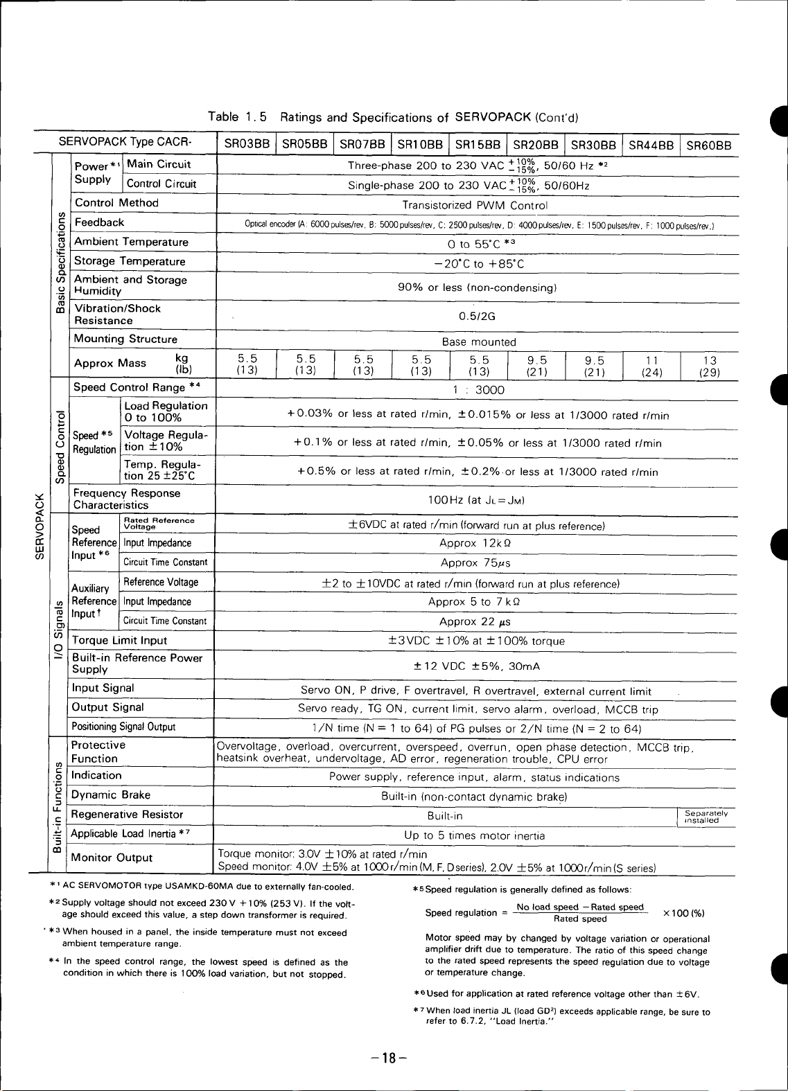
Table 1.5 Ratings and Specifications of SERVOPACK (Cont'd) am
,qu
,do
SERVOPACK Type CACR- SR03BB ] SR05BB I SR07BB _ SR15BB I SR20BB 6_ SR60BB
Power*_ I Main Circuit Three-phase 200 to 230 VAC _ 15%,
Supply Control Circuit Single-phase 200 to 230 _/^r+10% 50/60Hz
Control Method Transistorized PWM Control
Feedback Optical enc0der (A: 6000 pulses/ ev, B 5000puses/rev, C: 2500pulses/rev. D: 4000pulses/rev, E: 1500pulses/rev, F: 1000 pulses/rev,)
Ambient Temperature O to $5°C .3
_ Storage Temperature -20°C to +85°C
u_ Ambient and Storage
o I-lumidity 90% or less (non-condensing)
Resistance 0.5/2G
a_ Vibration/Shock
Mounting Structure Basemounted
Approx Mass kg 5.5 I 5.5 5.5 5.5 I 5.5 9.5 9.5 11 13
Speed Control Range .4 1 ' 3000 I
Load Regulation
Oto 100% +0.03% or less at rated r/rain, -+O.015% or less at 1/3000 rated r/rain
Speed*e Voltage Regula-
-o Regulation tion ---10% +O.1% or less at rated r/rain, -+0.05% or less at 1/3000 rated r/rain
'_ tion25+25°C
u_
Frequency Response
Charactenst_cs
£1 Rated Reference +6VDC at rated r/rain (forward run at plus reference)
Speed Voltage -- •
O ReferenceInputImpedance Approx 12k Q
co Input _,e CircuitTimeConstant Approx 75#s
Temp. Regula-
(Ib) (13) I (13) (13) (13) i _,o_ (21) (21) (24) (29) .din
+0.5% or less at rated r/min, +0.2%or less at 1/3000 rated r/min
1O0Hz(atJL=JM)
+10% 50/ Hz*2
v_ _ 15%,
1
Auxiliary ReferenceVoltage 4-2 to _-----F10VDCat rated r/rain (forward run at plus reference)
ReferenceInputImpedance Approx 5 to 7 kP,
Inputt
.__ CircuitTimeConstant Approx 22 #s
cn Torque Limit Input +3VDC + 10% at --4-100% torque
O
"" Built-in Reference Power
Supply -+ 12 VDC -+5%, 3OmA
Input Signal Servo ON, P drive, F overtravel, R overtravel, external current limit •
Output Signal Servo ready, TG ON, current limit, servo alarm, overload, MCCB trip
PositioningSignalOutput 1/N time (N = 1 to 64) of PG pulses or 2/N time (N = 2 to 64)
Protective Overvoltage, overload, overcurrent, overspeed, overrun, open phase detection, MCCB trip,
Function heatsink overheat, undervoltage, AD error, regeneration trouble, CPU error
o Indication Power supply, reference input, alarm, status indications
Dynamic Brake Built-in (non-contact dynamic brake)
_"_"Regenerative Resistor Built-in I _nstalledSeparately
"_ Applicable Load Inertia .7 Up to 5 times motor inertia
05
Monitor Output Torque monitor: 30V ___10%at rated r/min
_'_ AC SERVOMOTOR type USAMKD-6OMA due to externally fan-cooled. _'eSpeed regulation is generally defined as follows:
2Supply voltage should not exceed 230 V + 10% (253 V). If the volt- No load speed --Rated speed
age should exceed this value, a step down transformer is required. Speed regulation = Rated speed X 100 (%)
• _,3 When housed in a panel, the inside temperature must not exceed Motor speed may by changed by voltage variation or operational
ambient temperature range, amplifier drift due to temperature. The ratio of this speed change
,I,4 In the speed control range, the lowest speed is defined as the to the rated speed represents the speed regulation due to voltage
condition in which there is 1OO% load variation, but not stopped, or temperature change.
Speed monitor: 4.0V 4-5% at 1000r/min(M, F,Dsenes), 2.0V 4-5% at 1000r/min(S series)
e Used for application at rated reference voltage other than ± 6V.
• TWhen load inertia JL (load GD 2) exceeds applicable range, be sure to
refer to 6.7.2, "Load Inertia."
1
I
-18-
Page 20

DESIGNATION
USAFED- 05DA 1
T "- '---T ADDITtON SPECIFICATION
J (Sseries 03 to 30, M series44)
, DRIVE END SPECIFICATION
" • Blank: Standard
Type • S: WithShaftSeal
Externally • T: With Keyway& ShaftSeal"
Type
ORDER
M Series F Series S Series D Series
02 - 0.15kW (0.2HP) 0.15kW (0.2HP) -
03 0.3kW (0.4HP) 0.3kW (0.4HP) 0.31kW (0.4HP)
05 .- 0.45kW (0.6HP) 0.46kW (0.6HP) 0.5kW (0.7HP)
06 0.6kW (0.8H P) - - -
08 ,- - 0.77kW (1.1HP) -
09 0.9kW (1.2HP) 0.85kW(1.2HP) - -
10 - - - 1.0kW(1.3HP)
12 1.2kW (1.6HP) - - -
13 - 1.3kW (1.7H P) - -
15 - - 1.54kW (2.0HP) 1.5kW (2.0HP)
20 2.0kW(2.7HP) 1,8kW(2.4HP) - -
22 - - - 2.2kW(2.9HP)
30 3.0kW (4.0HP) 2.9kW (3.9HP) 3.08kW (4.0HP)' -
37 - - - 3.7kW(5.0HP)
44 4.4kW(5.9HP) 4.4kW (5.9HP) - -
60 6.0kW(8.0HP) - - -
M Series F Series S Series D Series
02 - 0.15kW (0.2HP) 0.15kW (0.2HP)
03 0.3kW (0.4H P) 0.3kW (0.4H P) 0.31kW (0.4H P)
05 - 0.45kW (0.6HP) 0.46kW (0.6HP) 0.5kW (0.7HP)
07 0,6kW(0.8.HP) - - -
10 0.9kW (1.2HP) 0.85kW (1.2HP) 0.77kW (1.1HP) -
15 1.2kW (1.6HP) 1.3kW (1.7HP) 1.54kW (2.0HP) 1.0kW (1.3HP)
20 2.0kW (2.7HP) 1,8kW (2.4HP) - 1.5kW (2.0HP)
30 3.0kW (4.0HP) 2.9kW(3.9H.P) 3.08kW (4.0HP) 2.2kW (2.griP)
44 4.4kW (5.9HP) 4.4kW (5.9HP) - 3.7kW (5.0HP)
• SHAFTTYPE
• Blank: Standard
• B: With Brake
• E: With Brake
(F series 02 to 44, M series 03 to 30, D series)
• O: Standard (With Brake)
• K: With Keyway
• 1: Taper
• 2: Straight
DETECTOR (Table 2.3)
. Table 2.1
Motor Output
Table 2.2
Motor Output
-19-
Page 21

•SERVOPACK Table2.3 •
EncoderResolution(P/R) Series Type
CACR - SRO5BC1 AF USAMEO-03CA_06CA
,din
'qB
SERVOPACKSERIES -44BA
CONTROLTYPE USAFSD-02DA
SR:Speed 6000 -09DA
MOTOROUTPUT -13CA
(Table2.2) to
APPLICATION -44CA
B: M,F,SSeries USADSD-05EA
DESIGN REVISION _ - 37EA
ORDER USAMED-03CB
INPUTFORM -06CB
1:200V,Analog to
DETECTOR _ -44BB
(Table2.4) USAFED-02DB
APPLICABLEMOTOR 5000 to
SERIES F -13CB
• M: M Series
•F: FSeries to
•S: SSeries -440B
•D: DSeries USADED-05EB
___J to
to
__ ...... M -09BA
4000 to
2500 to
1500 S to
i000 to
F
D to
M -09BB
- 09DB
D to
USAMED - 03CD
M -09BD
USAFED - 02DD
F - 13CD
D to
USADED - 05ED
USASEM - 02AC
USASEM - 02AE
USASEM - 02AF
- 06CD
-37EB
to
- 44BD
- 09DD
to
- 44CD
- 37ED
- 30AC
- 30AE
- 30AF
1
I
Table 2.4
Models pulses/rev pulses/rev
M Series A 6000 B 5000 D 4000
F Series A 6000 B 5000 D 4000 - _1_
S Series
D Series A 6000 B 5000 D 4000
Standard Optional Remarks
E 1500 C 2500 F 1000 02A, 03A, 05A
C 2500 E 1500 F 1000 08A, 15A, 30A
g
-20-
Page 22
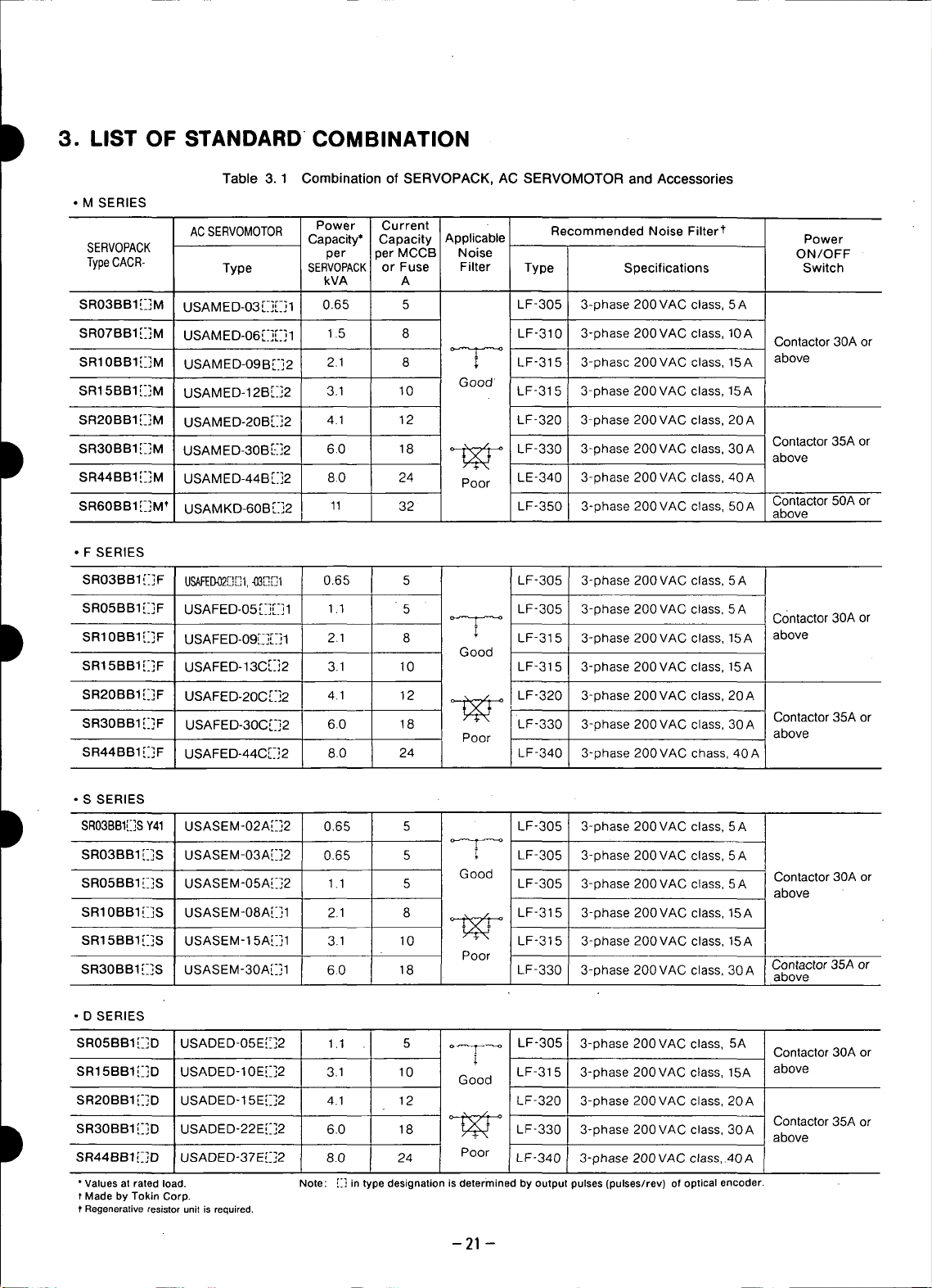
3. LIST OF STANDARD COMBINATION
Table 3.1 Combination of SERVOPACK, AC SERVOMOTOR and Accessories
• M SERIES
ACSERVOMOTOR Power Current Recommended Noise Filter1
SERVOPACK per )er MCCB Noise ON/OFF
TypeCACR- Type SERVOPACKor Fuse Filter Type Specifications Switch
SRO3BBI[_]M USAMED_O3r-]r-]I 0.65 5 LF-305 3-phase 200VAC class, 5A
SR07BB1E[IM USAMED-O6r-]r-]I 1.5 8 LF-310 3-phase 200VAC class, 10A
SR10BBIE]M USAMED-O9Br[]2 2.1 8 :_ LF-315 3-phasc 200VAC class, 15A above
SR15BB1[-_]M USAMED-12Br-]2 3.1 10 LF-315 3-phase 200VAC class, 15A
SR2OBB1 [-]M USAMED-2OBr-]2 4.1 12 LF-320 3-phase 200 VAC class, 20 A
D SR3OBBIE]M USAMED-3OBr--]2 6.0 18 _ LF-330 3-phase 200VAC class, 30A above
D SRIOBBI[-]F USAFED.O9r-]r-]I 2.1 8 _ LF-315 3-phase 200VAC class, 15A above
SR44BB1[-_3M USAMED-44Br[]2 8.0 24 Poor LE-340 3-phase 200VAC class, 40A
SR6OBBI[-]M _ USAMKD_6OBr-]2 11 32 LF-350 3-phase 200VAC class, 50A Contactor 50A or
• F SERIES
SRO3BB1 {-IF USAFED4)2[][]I,-03,[_%.',1 0.65 5 LF-305 3-phase 200 VAC class, 5A
SR05BB1E]F USAFED-O5r.-F]I 1.1 5 LF-305 3-phase 200VAC class, 5A
SR15BBl[_]F USAFED-13cr[]2 3.1 10 LF-315 3-phase 200VAC class, 15A
SR20BBI[[]F USAFED-2OCr_]2 4.1 12 _ LF-320 3-phase 200 VAC class, 20 A
SR3OBB1 [[IF USAFED-3OC.r-]2 6.0 18 tt/_ LF-330 3-phase 200 VAC class, 30 A Contactor 35A or
SR44BBf[[]F USAFED-44C[-]2 8.0 24 LF-340 3-phase 200VAC chass, 40A
- above
Capacity* Capacity Applicable Power
kVA A
Good
Good
Poor above
Contactor 30A or
Contactor 35A or
Contactor30Aor
• S SERIES
D SR03BBI[_]SY41 USASEM-02A['_]2 0.65 5 LF-305 3-phase 200VAC class, 5A
D SR3OBB1 [-]D USADED-22E[[]2 6.0 18 LF-330 3-phase 200 VAC class, 30 A above
SR03BB1 i-iS USASEM-03A[_]2 0.65 5 _; LF-305 3-phase 200 VAC class, 5 A
SRO5BBI[._]S USASEM-O5A[[]2 1.1 5 LF-305 3-phase 200VAC class, 5A
SR10BBI[-]S USASEM-O8AE]I 2.1 8 _ LF-315 3-phase 200VAC class, 15A
SR15BB1[._]S USASEM-15A[[]1 3.1 10 LF-315 3-phase 200VAC class, 15A
SR30BBI[_]S USASEM-30A[-]I I 6.0 18 LF-330 3-phase 200VAC class, 30A Contactor35Aaboveor
• D SERIES
SR05BBI[[]D USADED-O5E[[]2 1.1 5 i LF-305 3-phase 200VAC class, 5A
SR15BB1[_]D USADED-10E[-_]2 3.1 10 Good LF-315 3-phase 200VAC class, 15A above
SR2OBBI[[]D USADED-15E[-]2 4.1 12 LF-320 3-phase 200VAC class, 20A
SR44BBl[-]D USADED-37E,[_]2 8.0 24 Poor I LF-340 3-phase 200VAC class,.40A I
* Values at rated load. Note: [[] in type designation is determined by output pulses (pulses/rev) of optical encoder.
t Made by Tokin Corp.
t Regenerative resistor unit is required,
Good Contactor30Aor
Poor
-21 -
above
Contactor30Aor
Contactor35Aor
Page 23
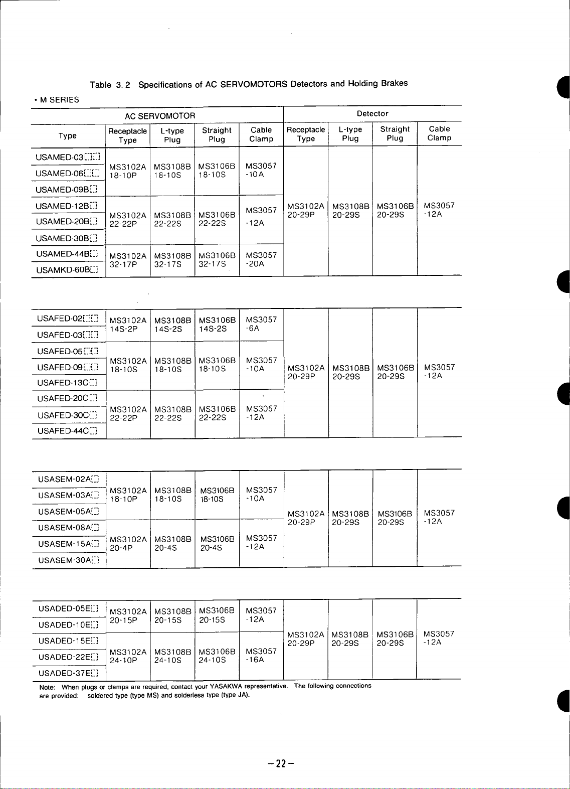
Table 3.2 Specifications of AC SERVOMOTORS Detectors and Holding Brakes I
• M SERIES
ACSERVOMOTOR Detector
Receptacle L-type Straight Cable Receptacle L-type Straight Cable
Type Type Plug Plug Clamp Type Plug Plug Clamp
USAMED-03 [:]E:]
MS3102A MS3108B MS3106B MS3057
USAM ED-06 [_-][_] 18-10P 18-10S 18-10S -10A
USAMED-O9B[-]
'qE
USAMED-12B[-] MS3057 MS3102A MS3108B MS3106B MS3057
USAMED2OBr-] 22-22P 22-22S 22-22S -12A
USAMED-3OB[[]
USAMED-44B[-] MS3102A MS3108B MS3106B MS3057
USAMKD-6OB[-] 32-17P 32-17S 32-17S -20A .,_
USAFED-02[-][.-] MS3102A MS3108B MS3106B MS3057
USAFED-03[-][-]
USAFED-05 [-][[]
USAFED-09[-][:] 18-10S 18-10S 18-10S -10A MS3102A MS3108B MS3106B MS3057
USAFED-13C[.-] 20-29P 20-29S 20-29S -12A
USAFED-20C[:]
USAFE D-30C[:] 22-22P 22-22S 22-22S -12A
USAFED-44C[-]
USASEM-02A[[]
USASEM-O3A[-]t8-10P 18-10S 18-10S -10A
USASEM-05A[-] MS3102A MS3108B MS3106B MS3057
USASEM-08A[-] 20-29P 20-29S 20-29S -12A
USASEM-15A[-] 20-4P 20-4S 20-4S -12A
USASEM-30A[-]
MS3102A MS3108B MS3106B 20-29P 20-29S 20-29S -12A
14S-2P 14S-2S 14S-2S -6A
MS3102A MS3108B MS3106B MS3057
MS3102A MS3108B MS3106B MS3057
MS3102A MS3108B MS3106B MS3057
MS3102A MS3108B MS3106B MS3057
II
I
USADED-05E[-] MS3102A MS3108B MS3106B MS3057
USADED-10E[-] 20-15P 20-15S 20-15S -12A
MS3102A MS3108B MS3106B MS3057
USADED-15E[_] 20-29P 20-29S 20-29S -12A
MS3102A MS3108B MS3106B MS3057
USADED-22EE] 24-t0P 24-10S 24-10S -16A
USADED-37E[-_]
Note: When plugs or clampsare required,contact /our YASA_A representative. Thefollowing connections
are provided: solderedtype (typeMS)and solderlesstype(type JA). ,_
-22-
11
Page 24
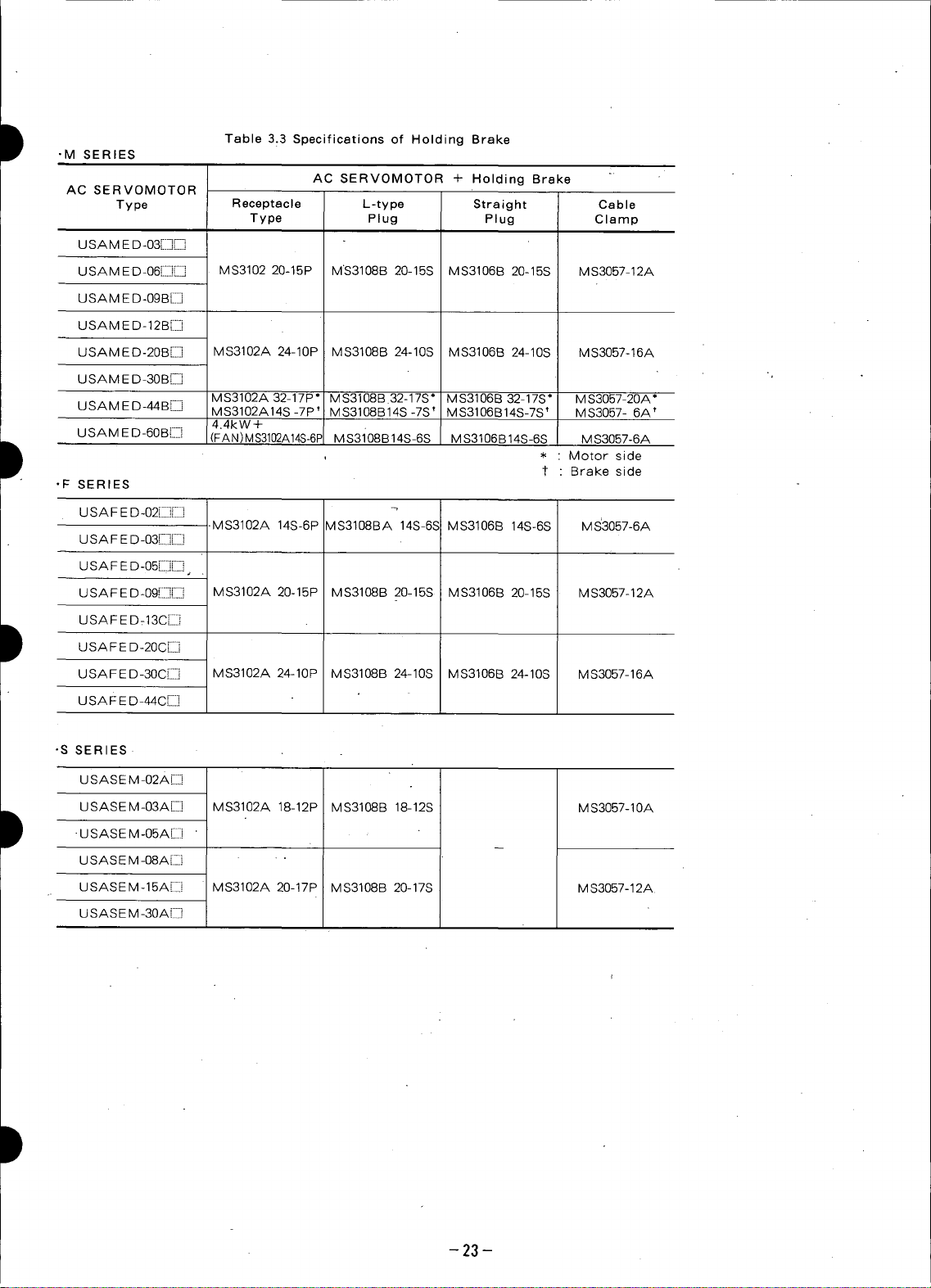
I Table 3.3 Specifications of Holding Brake
•M SERIES
AC SERVOMOTOR
Type Receptacle L-type Straight Cable
U S A M E D-03[]I]]
USAMED-06[][] MS3102 20-15P MS3108B 20-15S MS3106B 20-15S MS3057-12A
U S A M E D-09 B [iii:i:]
USAM E D-12B[]
USAMED-20B[[] MS3102A 24-10P MS3108B 24-10S MS3106B 24-10S MS3057-16A
U SA M ED-30 B{_-.]
USAMED-44B[] MS3102A14S-7P * MS3108B14S-7S t MS3106B14S-7S t MS3057- 6A t
USAM E D-60Bi[] (FAN) MS3102A14S-6F MS3i08B14S-6S M $3106B14S-6S M $3057-6A
-F SERIES
Type Plug Plug Clamp
MS3102A 32-17P ° MS3108B.32-17S* MS3106B 32-17S* MS3057-20A*
4.4kW+
AC SERVOMOTOR + Holding Brake : '
¢ Brake side
* Motorside
USAFED-02[iiq
U SA F E D-03L..JL....i .
U S A F E D-05[][[], .'
USAFED-09iiFI MS3102A 20-15P MS3108B 2045S MS3106B 20-15S MS3057-12A
USA F E D :13C[]
I USA FE D-20C[[i
USAFED-30C[] MS3102A 24-10P MS3108B 24-10S MS3106B 24-10S MS3057-16A
USA F E D-44C[]
• S SERIES=
U S A S E M -02A Eli
USASEM-03A[::] MS3102A 18-12P MS3108B 18-12S MS3057-10A
I -U SAS EM-05A[[] '
U SAS EM -08A[::] " •
USASEM-15A[:::::i MS3102A 20-17P MS3108B 20-17S MS3057-12A
U SAS E M -30A[:::::]
-MS3102A 14S-6P VlS3108BA 14S-6S MS3106B 14S-6S MS'3057-6A
-23-
Page 25
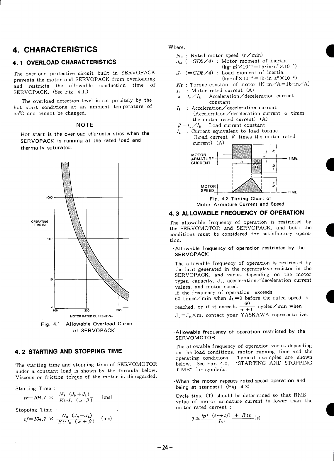
4. CHARACTERISTICS Where, •
NR : Rated motor speed (r/rain)
4.1 OVERLOAD CHARACTERISTICS JM (=GD_/4) : Motor moment of inertia
The overload protective circuit built in SERVOPACK JL (=GD[/4) : Load moment of inertia
prevents the motor and SERVOPACK from overloading (kg" n{ × 10- 4 = lb-in" s 2 x 10- 3)
and restricts the allowable conduction time of Kt : Torque constant of motor (N'm/A=lb'in/A)
SERVOPACK. (See Fig. 4.1.) IR : Motor rated current (A)
The overload detection level is set precisely by the constant
hot start conditions at an ambient temperature of Is : Acceleration/deceleration current
55°C and cannot be changed. (Acceleration/deceleration current a times
NOTE fl =IL/IR : Load current constant
Hot start is the overload characteristics when the IL : Current equivalent to load torque
SERVOPACK is running at the rated load and current) (A)
thermal ly saturated. I_%_,,:_1 l
a =I_/IR : Acceleration/deceleration current
the motor rated current) (A)
(Load current fl times the motor rated
MOTOR _NN N_:
ARMATURE t' I f _TIME
CURRENT I _ - [_| _,
(kg.rr_X10-' =lb'in's 2 ×10 -3)
, I_ T_
1
MOTOR_
SPEED ] = TIME
1000 Fig. 4.2Timing Chart of
Motor Armature Current and Speed
' I
4. 3 ALLOWABLE FREQUENCY OF OPERATION
OPERATING The allowable frequency of operation is restricted by
TIME (S) I
100 tion.
k .Allowable frequency of operation restricted by the
,0 __ values,types'capacity, JL, acceleration/decelerationcurrentandmotor speed.
2100 200 300 m
MOTOR RATED CURRENT (%) JL = JM X m, contact your YASKAWA representative.
Fig. 4.1 Allowable Overload Curve
of SERVOPACK -Allowable frequency of operation restricted by the
4. 2 STARTING AND STOPPING TIME on the load conditions, motor running time and the
The starting time and stopping time of SERVOMOTOR below. See Par. 4.2, "STARTING AND STOPPING
under a constant load is shown by the formula below. TIME" for symbols.
Viscous or friction torque of the motor is disregarded.
Starting Time : being at standstill (Fig. 4.3).
tr=104.7 × NR (JM+JL) (ms) Cycle time (T) should be determined so that RMS
Stopping
Time
tf=104.7 X Kt.I_ (a+fl) In'
Kt'IR (a-fl) value of motor armature current is lower than the
NR (JM+JL) (ms) T_Ip_ (tr+t/) + I[ts (s)
_ 60 times/min when JL=0 before the rated speed is
the SERVOMOTOR and SERVOPACK, and both the
conditions must be considered for satisfactory opera-
SERVOPACK
The allowable frequency of operation is restricted by
the heat generated in the regenerative resistor in the
SERVOPACK, and varies depending on the motor
If the frequency of operation exceeds t_
reached, or if it exceeds -- cycles/rain when
SERVOMOTOR
The allowable frequency of operation varies depending
operating conditions. Typical examples are shown
•When the motor repeats rated-speed operation and
motor rated current : •
6O
II
II
- 24-
Page 26

Where cycle time IT) is determined, values Ip, tr, 4. 4 SERVOMOTOR FREQUENCY
) tf satisfying the formula above, should be specified.
' SERVOMOTOR, motor speed amplitude is restricted by
MOTOR
ARMATURE = T_ME
CURRENT I l ,, I " Itml 1-_I I ; I_!
| _ the maximum armature current controlled by
1
I" ; T I'J_l Trl ] I I_;I The relation between motor speed amplitude IN) and
t_--_ _ _ _ frequency If) is shown by the formula below :
In the serve drive consisting of SERVOPACK and
SERV©PACK.
MOTOR _ _;_'¢;.'_ l I " " "
SPEED I ...._'_'_':_"_ (JM+JL) f
When the motor remains at standstill between cycles _,_ ;!_;_ --t ARMATURE
of acceleration and deceleration without continuous f_ !'_
. j L/
rated speed running (Fig. 4.4).
The timing chart of the motor armature current and N - ._
speed is as shown in Fig. 4.4. The allowable . . /_:_;_ MOTOR
lows:frequencyoperation can as __ . _
n=286"5X NR ('-]M+JL)" X a- _-_ Motor Armature Current end Speed
MOTOR _ -_
ARMATURE
MOTOR TIME to +10V. See Fig.4.8.
SPEED I The forward motor rotation (4-) means counter-
• When the motor accelerates, runs at constant speed,
and decelerates in a continuing cycle without being at
standstill (Fig. 4.5). RATED ADJUSTABLE WITH
I"_' ;_g!}:k ; _ I N = 1.52 X (r/min)
I/;Y(_:_:,::,;:_:,_._'lll I TIME
I
Fig. 4.3 Timing Chart of _ Ip=ala_
Motor Armature Current and Speed
' o
of "n" be calculated fol- _;_< _!_:_y _] _t SPEED
Kt.IR [1 _)21. Fig. 4.6 Timing Chert of
(times/min)
4.5 MOTOR SPEED-REFERENCE INPUT
_;_ _ - _ _ -
I
"_:_ } l I _; TIME Fig. 4.7 shows motor speed and input voltage curve
_!:*:_!iI [ i:_!_ when speed reference input terminals 1CN-@ and @ areCURRENT ( ;_ _ , _:_
I ' I I motor speed can be set to the rating by adjusting]iN-B]
i _:,_:;_1 II I N_: used. With auxiliary input terminals, 1CN-@ andr= _
_ i _ i potentiometer as long as input voltage is within +2V
Fig. 4.4 Timing Chart of clockwise (CCW) rotation-when viewed from the drive
Motor Armature Current and Speed end.
speed is as shown in Fig.4.5. The allowable frequency I
The timing chart of the motor armature current and SPEED (+) / I RATEDSPEED(+) -- -- ,
of operation "n" can be calculated as follows : t
Kt'I, [ 1 [?' ] t I /2/ I I t , ' , , ,. ' ....--6--4 0 2 4 6 -10-8-6-4-21 } 4 6 8 1'0
n=286.5X N. (g_+JL) × [ -- - - J i / INPUT ', /:/ INPUT VOLTAGE(V)
MOTOR I Fig. 4.8
ARMATURE I i J I_!_!! , I_;_I = TIME Fig. 4.7 Speed-Input Voltage
CURRENT - _ a _ Speed-lnput Voltage Characteristics
MOTOR I I
SPEED _ _TIME "
i _l_'_il • _ when Auxiliary Input
I _ _i-,i._l II Characteristics .
II II
I • I
' _ o _ _ Terminals 1CN-@ /
a a VOLTAGE IV) _ /,[
(times/rain) I___ __II ' :
RATED
SPEED (--)
' _-----;_- _ATED SPEED(-)
and(_)are.used.
I 4.6 MOTORMECHANICALCHARACTERISTICS
Fig. 4.5 Timing Chert of
Motor Armature Current and Speed 4.6.1 Mechanical Strength
AC SERVOMOTORS can carry up to 300% of the rated
-" - momentary maximum torque at output shaft:
-25-
Page 27

4.6.2 Allowable Radial Load and Thrust Load 4.6.4 Direction of Rotation •
Table 4.1 shows allowable toads according to AC AC SERVOMOTORS rotate counterclockwise (CCW)
SERVOMOTOR types, when viewed from the drive end when motor and detec-
tor leads are connected as shown below.
Table 4.1 M Series Allowable Radial Load
and Thrust Load
,all
II
Motor Type Allowable Allowable
USAMED- N(Ib) N(Ib)
03[:][:]1 490 (110) 98 (22) t
06 [:][:] 1 490 (110) 98 (22) t
09B[:]2 686 (154) 343 (77)
12BE]2 1470 (330) 490 (110)
20B[;]2 1470 (330) 490 (110)
30B[:]2 1470 (330) 490 (110) Fig. 4.9 AC SERVOMOTOR
44B[_]2 1764 (397) 588 (132)
USAMKD-6OB[:] 2 1764 (397)' 588 (132)
Table 4.2 F Series Allowable Radial Load SERVOMOTORS
Motor Type Allowable Allowable
USAFED- N (Ib) N (Ib)
02[:][:]1 147(33) 49( 11)t
05 [:][_]1 490 (110) 98 (22) t B Phase V
09 [:][:]1 490 (110) 98 (22) t
13C[:]2 686 (154) 343 (77) C Phase W
03,:_],,'_]1 147 (33) 49 ( 11)t @ A Phase U
20CE]2 1470 (331) 490 (110)
30C[:]2 1470 (331) 490 (110) D Frame ground
44cE]2 1470(331) 490 (110)
Table 4.3 S Series Allowable Radial Load (Type USASEM-02A)
Motor Type Allowable Allowable
USASEM- N(Ib) N(Ib)
O2AE]2 78.4 (18) 39.2 (9) Red Phase U
03A[:]2 245 (55) 98 (22) White Phase V
05A[_] 2 245 (55) 98 (22)
08A[:] 1 392 (88) 147 (33)
15AE]I 490 (110) 147 (33)
30A[:]1 686 (154) 196 (44)
Radial Load* Thrust Load
386-5
(i) Connector Specifications for Standard
and Thrust Load (a) Motor receptacle
Radial Load* Thrust Load " M, F Series
• S Series
and Thrust Load
Radial Load* Thrust Load Color of Lead Applicable
Blue Phase W
I
q
Table 4.4 D Series Allowable Radial Load (Types USASEM-03A to 30A)
Motor Type Allowable Allowable
USADED- N(Ib) N (Ib)
O5E[-]2 686 (154) 343 (77) C Phase W
10E[:]2 686 (154) 343 (77)
15EE]2 1176 (265) 490 (110) D Frame ground
22E[:]2 1176 (265) 490 (110)
37E[:]2 1176 (265) 490 (110) (b) Detector receptacle
* Maximum values of the load applying to the shaft extension.
t Do not apply the exceeding load because motor cannot be rotated. _ A Channel A output K Channel U output
4.6.3 Mechanical Specifications
(M, F, S and D Series) C ChannelB output M ChannelV output
Table 4.5 Mechanical Specifications in mm
Flange surface 0.04
perpendicular to shaft _) (0.06) * /-__ G 0V S - __
Flange diameter
concentric to shaft ® 0.04 H +hVDC T -
Shaft run out © 0.02 J Frame ground -- -
Accuracy (T.I.R)t Reference Diagram F Channel _ output R Channel W output
* Accuracy for motor types USADED-15E, -22E, and -37E.
* T.I.R (Total Indicator Reading)
t Accuracy for motor types USAMED-44M[_2 and USAMKD-60M[_-J2.
and Thrust Load _ A PhaseU
Radial Load* Thrust Load B Phase V
B Channel _ output L Channel -U output
D Channel -B output N Channel ? output
E Channel Z output P Channel W output
(0.04) _ i
-26-
I
Page 28

t (2) Connector Specifications for SERVOMOTOR with Arrange the main circuit sequence to stop the
Brake SERVOMOTOR and fan motor when cooling fan alarm
occurs. (Alarm contact is ON at alarm occurrence).
• M, F*, D Series (Brake is provided to all types of D After alarm occurrence, make sure to stop the
series as standard.) SERVOMOTOR and fan motor within five minutes
B Phase V F Brake terminal five minutes.
When cooling fan starts running, alarm detection
C Phase W G - signal turns ON for three seconds. Therefore, add a
A Phase U E since SERVOMOTOR self-cooling protection is set to
D FrameGround -- - delay relay to the circuit for this time setting (three
Types without brake of 13 series do not use seconds).
E and F.
4.6.5 Impact Resistance.
*For USAFEM-02 and-03,
seeconnector on the right. When mounted horizontally and exposed to vertical
shock impulses, the motor can" withstand up to two im-
pacts with impact acceleration of 490m/s2(50G) (Fig.
• S Series 4.11).
(USASEM-02A).. NOTE
t A precision detector is mounted on the opposite-
Color of Lead Applicable Color of Lead Applicable drive end of AC SERVOMOTOR. Care should
Red Phase U Black .. be taken to protect the shaft from impacts that
White Phase V Black
Brake could damage the detector.
Blue PhaseW Green Frame Ground IVERTICAL
(USASEM-03A, -05A) (USASEM-08A to -30A) ' --_- IIIIL_=,ZONTAL
t O O Fig. 4.11 Impact ResistanceL I IUJ"V'"
4.6.6 Vibration Resistance
A PhaseU A PhaseU When mounted horizontally, the motor can withstand
B Phase V B Phase V vibration (vertical, lateral, axial) of 24.5m/s 2 (2.5G)
C Phase W - C Phase W (Fig. 4.12).
Brake terminal Brake terminal
E E LAT . L
!
VERTICAL
t F FLameground F Frameground
(3) Fan terminal connector specifications [L_ HORIZONTAL
(Type USAMKD-60BEI]2)
A Fan motor CONNECTION
B Fan motor 4.6.7 Vibration Class
C - Vibration of the motor running at rated speed is 15/_m
D Alarm terminal - or below (Fig. 4.13).
E Alarm terrain,31 POSITION FOR
F -- I IPower Supply: Single-phase 200V,50/60Hz, __
Alarm Contact: OFF when fan is running normally
ON when fan rotation is 1800 +200
r/min or less. Fig. 4.13 Vibration Checking
When cooling fan starts running,
I ONfor 3 seconds.
Contact Capacity: Resistance load is ll0V max, 0.3A 4.6.8 Holding Brake
Fig. 4.10. Fan Terminal Connection Turn ON/OFF according to Par. 6.9.3, "Application
Fig. 4.12 Vibration Resistance
SHADING COIL
CHECKING VIBRATION
of SERVOMOTORS with Holding Magnetic Brake"
since AC SERVOMOTORS with brake is used when the
operation is held.
-27-
Page 29

5.CONFIGURATION 4
5. 1 CONNECTION DIAGRAM
POWER SUPPLY
200 TO 230V +10%
50160 Hz
1MCCB )
-15
Prevent external noise with a noise filter.
f
S NOISE FILTER 1 _ Bold lines indicate power lines
-- _ INDICATION)
_ 1MC: / SERVOPACK
: 1MC| I [CACR-SR J _
(excluding the grounding line). (SERVO TROUBLE
5 Ry _ EXAMPLES OF INDICATION
POWER
POWER ON 5 Ry MAGNETIC CONTACTOR
---.C) I ____-_O O _ 1 Be .... to fit a surge suppressing
OFF --L_ __ _FOR POWER ON/OFF 4
1MC 1SUP i tor and the relay.
1Me a I R "_ U _ ALARM
=_'_1-_- device to both the magnetic contac-
g
,t '_s / TYPE | v_
/ cIRcuIT I _
• : 4
SPEED LEAD LENGTH grounded
REFERENCE 3 METERS OR LESS ,/_.
mPim
P t ( CONNECTING CABLE: ,_
Use relays highly reliable in
contact(YASKAWABestact O TYPEJUSP-RA03
relays or equivalent, or arrange 2 R._.yy .5mA
intwocontactparallelconnec- Y3
tion for low level). 3 Ry 5mA
1 Ry 5mA *RESISTOR UNIT
4 Ry 5_mA
I, Y4
5 Ry
JTERMINALS \7._ _M_besecurely
2Ch I I
(_
1CN Be sure to perform terminal trearment
of shielded cable
i
LEAD LENGTH:
20 METERS OR LESS
YASKAWA DRAWING
No, DP8409123 OR
No, DE8400093
I
+ 24V _ 1V (If connection is wrong, output transistor is damaged). ..,.]
(SUPPLIED BY USER)
Connect the output relay surge absorbing diode with the correct polarity
*Added only for SERVOPACK type CACR-SR60BB
(externally fan-cooled type).
Fig. 5. 1 ExampleofConnectionDiagramofSERVOPACK
witha SERVOMOTORandPeripherals
-28-
(I
Page 30

Page 31

Page 32

D 5. 3 EXTERNAL TERMINALS 5.4 CONNECTOR TERMINAL (1CN) FOR
Table 5.1 shows the specifications of external terminals INPUT/OUTPUT SIGNALS
for SERVOPACK.
5.4.] Specifications of Applicable Receptacles
Table 5.1 External Terminals for SERVOPACK
Table 5.2 Specifications of Applicable Receptacles for
Terminal SERVOPACK Input/Output Signals
Symbol Name Description
(_) ® (!) AC input 50/60 Hz. SERVOPACK Case
Main-circuit Three-phase 200 to 230 VAC,_15 _, Manu- Soldering Caulking
+10o used in Type
Connector Type* Applicable Receptacle
MR-50RMA Honda
facturer Type Type
Motor Connects terminal Q to motor (Right angle Tsushin MR-50F t MRP-
@ O _ connection terminal A, _) to B and _ to C. 50 P) Co., Ltd. 50F01 MR-50Lt
Q O input 50/60Hz MR-50RMA made by Honda Tsushin Co.
Control power Single-phase 200 to 230 VAC +10oz
-15/°, * The connectors for input/output signals usedere type
t Attached to SERVOPACK prior to shipment.
(_ Ground Connects to motor terminal FG.
D Must be securelygrounded.
Regenerative External connection not normally required
(_) (_ resistor except SR60BB.
5.4.2 Connector 1CN Layout and Connection
of SERVOPACK
The terminal layout of the SERVOPACK inputJoutput
signal connectors (1CN) is shown in Table 5.3.
The external connection and external signal processing
D are shown in Fig. 5.4 on page 32.
Table 5.3 Connector tCN Layout of SERVOPACK
1 2 3 4 5 6 7 8 9 10 11 12 13 14 15 16 17 18
0 V 0 V 0 V PHA CLT+ CLT- +24V
0 V for PG Output SignaIPGOutput Current Limit Ext Servo Speed Monitor SpeedReference Auxiliary 4- 12V j Frame
Signal 3haspA)t Detection Output Power ON
D 19 20 21 22 23 24 25 26 27 28 29 30 31 32
PCO *PCO PHC TGON TGON P-CON OL N-OT S-RDY S-RDY N-CL SG -12V SG
PG Output IPGoutput TG ON ! P Drive Overload Reverse Servo Ready Reverse Current -- 2 V
Signal(PhaseC) Ip_aseclt Signal Output Input DetectingProhibit
I Signal
IN S-ON TRQ-M VTG-M SG IN-A SG.A IN-B SG.B +12V SG FG
Input Power Torque monitor In)ut Input Output Ground
4- -- -- -- 4-
Signat Input Output Out )ut Out 3ut
33 34 35 36 37 38 39 40 41 42 43 44 45 46 47 48 49 50
PAO *PAO PBO *PBO PHB ALM+ ALM- OL P-OT MCCBMCCF P-CL SG -12V SG +12V SG FG
PGOutput PGOutput PGOutpu_Servo Alarm Overload Fwd. MCCB Trip Fwd. Current 12 V 4-12 V Frame
Signal(PhaseA) Signal(Phase B) (PhaseB)t Output Sighal Input Signal Oufput Limit Input Output Output Ground
Signal Detecting Prohibit
tOpen collector
4- -- +
4=
PG Output Signals External Sequence Signals Analog Signals
1: Opencollector
--31 --
Page 33
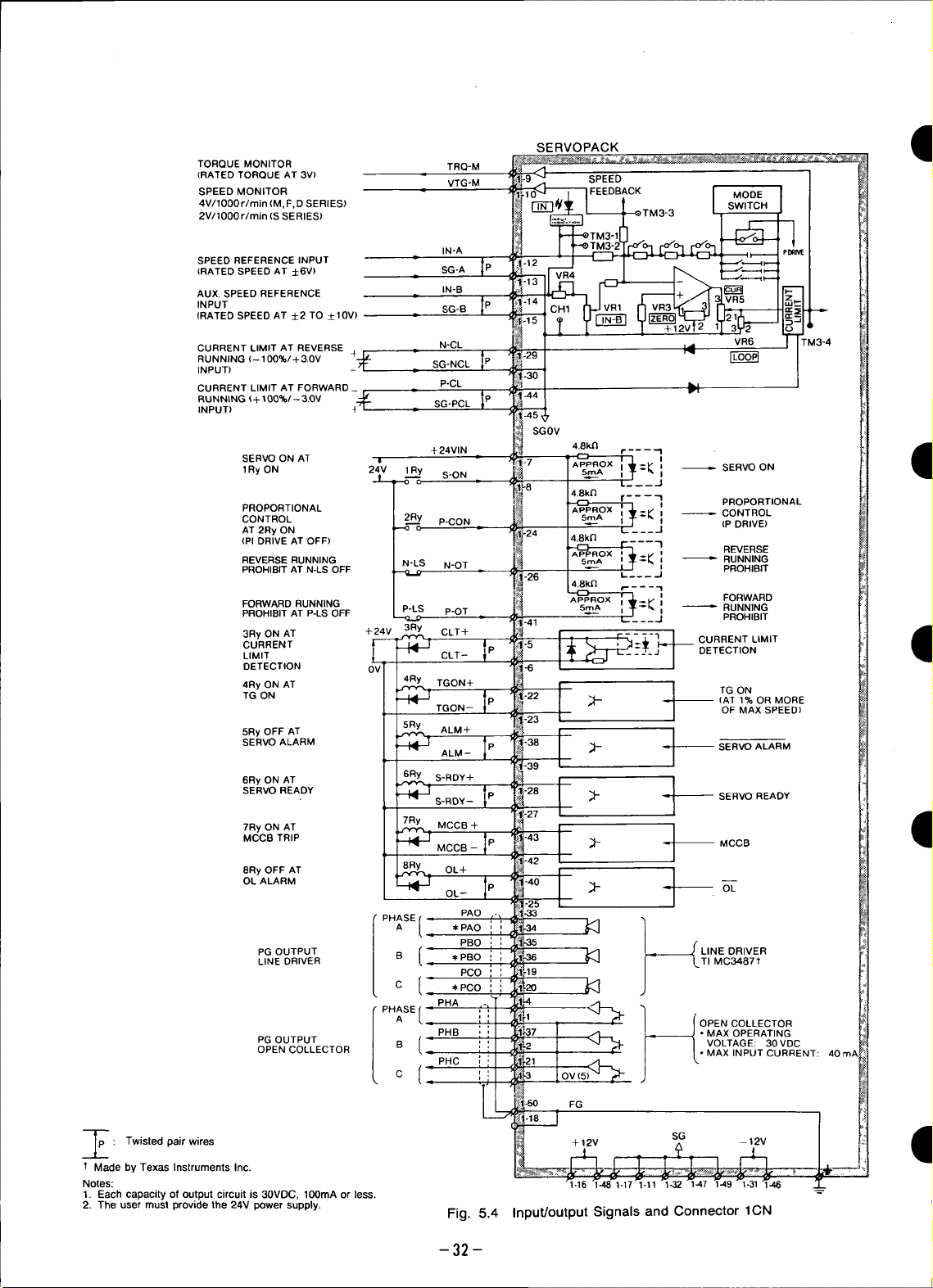
TORQUEMONITOR TRQ-M
(RATED TORQUE AT 3V)
SPEED MONITOR
4V/1000 r/min (M, F,D SERIES)
2V/1000 r/min (S SERIES)
VTG-M
SERVOPACK t
SPEED REFERENCE INPUT
(RATED SPEED AT ±6V) SG-A
AUX. SPEED REFERENCE IN-B
INPUT SG-B
(RATED SPEED AT ±2 TO _+10V)
CURRENT LIMIT AT REVERSE ._ N-CL _._
RUNNING (- 100%/+ 3.0V # SG-NCL
INPUT)
CURRENT LIMIT AT FORWARD _
RUNNING (+ t 00%/-- 3.OV _._
INPUT) 4 =
SERVO ON AT I
1RyON 21V 1Ry S-ON "=_ =1
PROPORTIONAL -- I
CONTROL 2Ry '.=_ iI = CONTROL
AT 2Ry ON _ P-CON ._ / (P DRIVE)
(PI DRIVE ATOFF) "I REVERSE
REVERSE RUNNING N-LS N-OT '._ [ " RUNNING
PROHIBIT AT N-LS OFF _ L_ _ _ .J PROHIBIT
FORWARD RUNNING =_^ ,_ .
PROHIBITAT P-LS OFF P-LS P-OT
3Ry ON AT +24V 3Ry CLT+ IN I _ _ r .... 1
CURRENT f---'-_?.-_ -5 CURRENT LIMIT
• c,,-IP !+
4Ry ON AT 4Ry TGON+ [_ | I
IN-A
P-CL
SG-PCL
SGOV
+ 24VIN 4.8k/1
_--5 .__j
4.8k_ r- - - - 7
APPROX I _ _i FORWARD
s _'"_ LT_ __.J PROHIBIT
|
i
TGON IP IT_-22I ;F- _ TG ON
TGON-- _ _ / OF MAX SPEED,
5Ry OFF AT ALM+ _
DETECTION 0fVl _ _-6 I - i
SERVOALARM I "38 1 I
6RyONAT 6Ry S-RDY+
ALM P . SERVOALARM
'39 I
S-ROY- P _ SERVO READY
•27 I
VR6
rc¢_
SERVO ON
PROPORTIONAL
RUNNING
(AT 1% OR MORE
MCO TR,P I I
8Ry OFF AT OL+ /
OL ALARM _ O"-L
,RyONAT I 'RYMOOR+P ' ' [I
PHASE{ *PAO
PG OUTPUT B * PBO i
LINE DRIVER LTI MC3487¢
PG OUTPUT =
OPEN COLLECTOR
: Twisted pair wires +12V SG -12V I
1"Made by Texas Instruments Inc.
Notes:
1. Each capacity of output circuit is 30VDC, 100mA or less. --"
2. The user must provide the 24V power supply.
MCCB - _L. MCCB
PAO
( PBO _ LINE DRIVER
PCO
C [ *PCO i
PHB • MAX OPERATING
/ VOLTAGE: 30 VDC
PHC
•42 I
• MAX INPUT CURRENT: 40 m_
FG
Fig. 5.4 Input/output Signals and Connector 1CN
-32 -
Ii
Page 34

D Table 5.4 Input Signals of Connector 1 CN
Signal Connector Function Description
Name ] CN No.
SV-ON 1 CN-8 Servo ON , speedreference input (+6V)
Inputting this signal makes the SERVOPACK ready to receive
Base block and dynamic brake are cleard.
P-CON ] CN-24 reference motionless without command input, while the mamc_rcmt _skept
N-OT 1CN-26
P-OT ] CN-41
24V 1CN:7 24V
IN-A 1 CN-12(13) Speed command input At +6.0V, 4- rated speed is obtained.
D At +2.0to +10.0V, 4- rated speed is obtained.
D Name I CN No. Function Description
D •N-CL P-CLused: TurnsON reaches
IN-B ] CN-14(15) Aux. command input For adjustment, potentiometer _ is used.
N-CL 1CN-29(30) Current limit reference +3.0V +10%/100% torque +9 V max.
P-CL ] CN-44(45) Current limit reference
Signal Connector
OL 1CN-40(25) detection Turns OFF when overload is detected. (SeePar. 4.1 "OVERLOAE:
MCB 1CN-43(42) MCCB trip Turns ON when MCCB trips.
ALM lCN-38(39) Servo alarm
TGON lCN-22(23) detection F Series: Approx 25r/min '
CLT ]CN-5(6) detection -N-CLorP-CLnotused: Turns ON When output torque
S-RDY 1CN-28(27) Servo ready Turns ON when main power supply ON, and no servo alarm.
Jr-12 V 1CN-16, 48
0 V 1CN-17,32,49 power supply Used with speed command or current input.
--12V 1CN-31, 46
TRQ-M 1CN-9 Torque monitor (Rated torque at-+3.0V) -+10%, +gVmax, IoadlmAmax
VTG-M 1CN-10 Speed monitor SSeries (-+2.0V/1000r/min) -+5%. Load: lmAmax
PAO 1CN-33
PAO 1CN-34
PBO 1CN-35 Positioning Pulse after frequency division is output line driver (TI MC3487).
,I,PBO 1CN-36 Output 1 To be received by line receiver (TI SN75115).
Proporitonal drive Proportional control command to prevent drifting when the motor is left
energ ized.
Reverse running
prohibit In the case of linear drive, etc connect limit switch signal according
Forward running to the run direction. This is a. normally closed contact.
prohibit
External power supply to 1 CN-8, 24, 26and 41. Use an. external
24VDC (20mA min.) power supply.
at reverse running
at forward running -3.0V +10%/100% torque -9 V max.
Table 5.5 Output Signals of Connector I CN
Overload Motor overload detection or heat sink overheat detection.
CHARACTERISTICS")
Turns OFF when fault is detected.
For details, refer to Table 6.2, "Fault Detecting Functions."
Turns ON when motor speed exceeds fol lowing speed.
Motor run M Series: Approx 20r/min D Series: Approx 25r/rain
S Seried: Approx 4Or/min
or
Current limit the level set by N-CL or P-CL.
reaches the level set by potentiometer _ .
+12V output +12V +5% max output current ' 30mA
M, F, DSeries (-+4.0V/1000r/min) -+5%.
Phase A
Signal Phade B
when
output
torque
D PCO lCN-19
_1,PCO lCN-20 Phase C
PHA 1CN-4(1) Positioning Phase A Open collector output, pulseafter frequency division.
PHB 1CN-37(2) Signal Phase B Max operating voltage: 30VDC.
PHC 1CN-21(3) Output2 Phase C Max mputcurrent: 40mA.
-33-
Page 35

5.5 CONNECTORTERMINAL(2CN)FOR •
OPTICAL ENCODER(PG) CONNECTION
5.5.1 Specifications of Applicable Receptacles and
Cables (Table 5.6)
Table 5.6 Specifications of Applicable Receptacles and Cables
ConnectorType* Applicable Receptacle Type Connection
used in
SERVOPACK Manufacturer Soldered Type Caulking Type Case t Cable_
MR-20RMA, Honda Tsushin MR_20F _ MRP-20F01 MR-20L_ DP8409123 or
right angle Co., Ltd. DE8400093
20P
" Made by Honda Tsushin Co., Ltd. = The cables listed in Table 5.7 are available on request.
t Attached to each applicable receptacle (soldered and If required, purchase in units of standard length as
caulking types), shown in Table 5.7.
: Attached to SERVOPACK prior to shipment.
41
"qm
Table 5.7 Cable Specifications NOTE
Connection Soldered Type I Caulking Type used, allowable wiring distance between
YASKAWA DP 8409123 DE 8400093 meters.
Drawing No. 2. The cable applied for 50m wiring distance is
Manufacturer Fujikura Cable Co. available on order (YASKAWA drawing No.
Double, KQVV-SW DP8409179).
Approx AWG 22X3C AWG 26X10P
Specifications AWG 26X6P your YASKAWA representative.
Finishing _8.0mm(@0.31in.) _10.0mm(_0.39in.) dor with appropriate tooling.
Dimensions
For Soldered Type For Caulking Type
Internal ' Yellow-
Composition A21Black 2 • White --1 I 2 I 3 I 4 I 5 I 6 I 7
and A 31Green-yello_ 3 White PGOV PGOV DIR
Lead Color B White/blueBlUe- 4 ' WhiteRed- ! ! PGOV110PG5V11PG5V12PG5V1,
AtlRed l White of SERVOPACK
Yellow* Purple- Twisted
B 2 .White/yell°w 5 , White pair
Green- Blue- wires
Ba White/green Twisted 6 Brown _ _E
•Orange- pair Yellow-
B 4 .White/°range wires 7 . Brown 1 20
Purple* Green*
B 5 White/purple 8 Brown
[
KQVV-SB If wiring distance is 20m or longer, contact
(_ 5.5.2 SERVOPACK Connector (2CN) Terminal i_
Blue-
Green-
1. When applicable cables listed in Table 5.7 are
SERVOPACK and motor is a maximum of 20
3. Cables must be assembled by authorized ven-
The terminal layout for the SERVOPACK connec-
tors (2CN) for connecting the optical encoder is
shown in Table 5.8, and the connection method of
2CN and the optical encoder, in Figs. 5.5 and 5.6.
Layout and Connection
Table 5.8 Connector 2CN Layout
I
10 Purple-
Brown
YASKAWA Standard length 5m, 10m, 20m
Standard Terminal ends are not provided
Specifications (with connectors).
-34-
Page 36
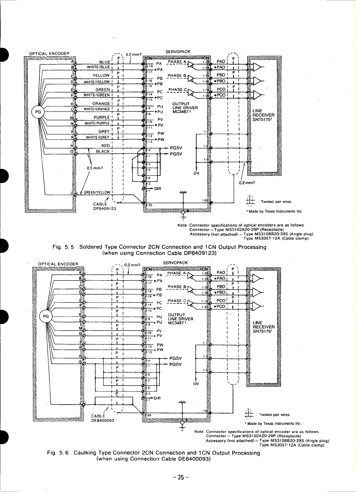
OPTICAL ENCODER t _', 0.2 mm 2 SERVOPACK
WHITE/BLUE I 2-_6
WHITE/YELLOWI
WHITE/GREEN I
ORANGE I OUTPUT
WHITE/ORANGEt
WHITE/PURPLE _'PV
WHITE/GREY
i p
BLUE PA PHASE A
YELLOW PHASEB
GREEN PHASEC
PURPLEI PV SN75175t
GREY PW
I
RED
BLACK I
PB
PC
"*PC
PU LINE DRIVER
MC3487t LINE
,e PW
RECEIVER
0.5 mm 2
IREEN/YELLOW
I"/ ',_--_: Twistedpairwires.
CABLE _-20 ..,
DP8409123 * Made by Texas Instruments Inc.
t Fig. 5.5 Soldered Type Connector 2CN Connection and 1CN Output Processing
OPTICAL ENCODER _-_ 0.2 mm2 __ SERVOPACK ,_
t OUTPUT
._j | I RECEIVER
N_
(when using Connection Cable DP8409123)
PHASE A
PA
PA
I P PHASEB
I l I PB
i I I *PB
I P I PHASE C
I PC
I PU LINEDRIVER
I _ __-1o _v SN75175 t
*PC
"
_* PV
_ PW
MC3487 t LINE
OV /
Note: Connector specifications of optical encoders are as follows.
Connector--Type MS3102A20-29P (Receptacle)
Accessory (not attached)- Type MS3108B20-29S (Angle plug)
0.2 mm2
Type MS3057-12A (Cable clamp)
, _ _ I t ' PGOV
t t 1 _.4 PG5V
I P I _-_
I I I -2
I P I _ OV
I
t i I _-s
CABLE _ : Twisted pair wires.
DE8400093
I : Note: Connector specifications of optical encoder are as follows.
_ )' ,._,.,
Fig. 5.6 Caulking Type Connector 2CN Connection and 1CN Output Processing
(when using Connection Cable DE8400093)
-35-
t Made by Texas Instruments Inc.
Connector--Type MS3102A20-29P (Receptacle)
Accessory (not attached)- Type MS3108B20-29S (Angle plug)
Type MS3057°12A (Cable clamp)
Page 37
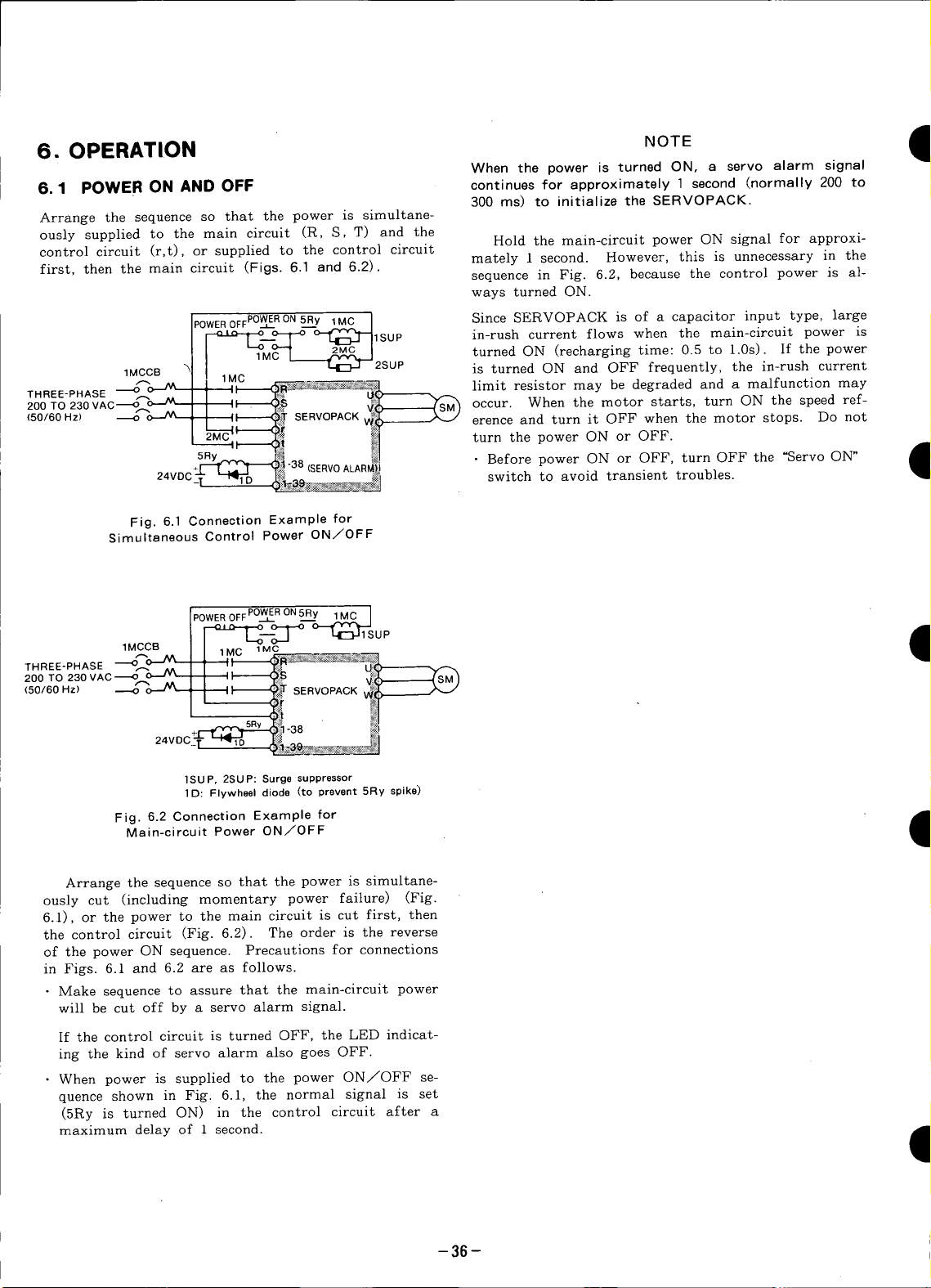
dl
6.OPERATION NOTE 11
When the power is turned ON, a servo alarm signal
6.1 POWER ON AND OFF continues for approximately 1 second (normally 200 to
Arrange the sequence so that the power is simultane-
ously supplied to the main circuit (R, S, T) and the
control circuit (r,t), or supplied to the control circuit
first, then the main circuit (Figs. 6.1 and 6.2) mutely 1 second. However, this is unnecessary in the
POWEROFFPOW__ERON5Ry 1MC I Since SERVOPACK is of a capacitor input type, large
__.o-_ _lSUP in-rush current flows when the main-circuit power is
• sequence in Fig. 6.2, because the control power is al-
300 ms) to initialize the SERVOPACK.
Hold the main-circuit power ON signal for approxi-
ways turned ON.
1MCCB is turned ON and OFF frequently, the in-rush current
THREE-PHASE _ 1 " _' U_
200 TO 230 VAC_r__ I II (_ __SM_ Occur. When the motor starts, turn ON the speed ref-
(50/60 Hz) _ ;-_ , I _ 6_ SERVOPACK ,,_
Fig. 6.1 Connection Example for
Simultaneous Control Power ON/OFF
1MCCB 1MC 1MC
I[ 1Mc_'MC'-'-- T _21_MC ]2SUP turned ON (recharging time: 0.5 to 1.0s). If the power
! ,, _, limit resistor may be degraded and a malfunction may
I I _ ,_ - - erence and turn it OFF when the motor stops. Do not
2MC' "f_ _:_ turn the power ON or OFF.
------_, q_! #] ,_m
5RY_v_____.38 _1 " Before power ON or OFF, turn OFF the "Servo ON"
+I'_[ :_: ]'_Y_t -o,-, (SERVO ALARM}j
24VDC_. _ I_.___ _, switch to avoid transient troubles•
POWER OFF POWER ON 5Ry 1 MC
---_D.____O O--_1 Up t
200TO230VAC----_o--'L'- ,I _S _----_JSM)
( o.6oH , ,, S .OPA¢
+_ !_1-38 _
24voc_i-"-_% .Ji! _
]SUP, 2SUP: Surge suppressor
1 D: Flywheel diode (to prevent 5Ry spike)
Fig. 6.2ConnectionExamplefor
Main-circuit Power ON/OFF
q
I
Arrange the sequence so that the power is simultane-
ously cut (including momentary power faiture) (Fig.
6.1), or the power to the main circuit is cut first, then
the control circuit (Fig. 6.2). The order is the reverse
of the power ON sequence. Precautions for connections
in Figs. 6.1 and 6.2 are as follows.
• Make sequence to assure that the main-circuit power
will be cut off by a servo alarm signal.
If the control circuit is turned OFF, the LED indicat-
ing the kind of servo alarm also goes OFF.
• When power is supplied to the power ON/OFF se-
quence shown in Fig. 6.1, the normal signal is set
(5Ry is turned ON) in the control circuit after a
maximumdelay of 1 second•
-36-
Page 38
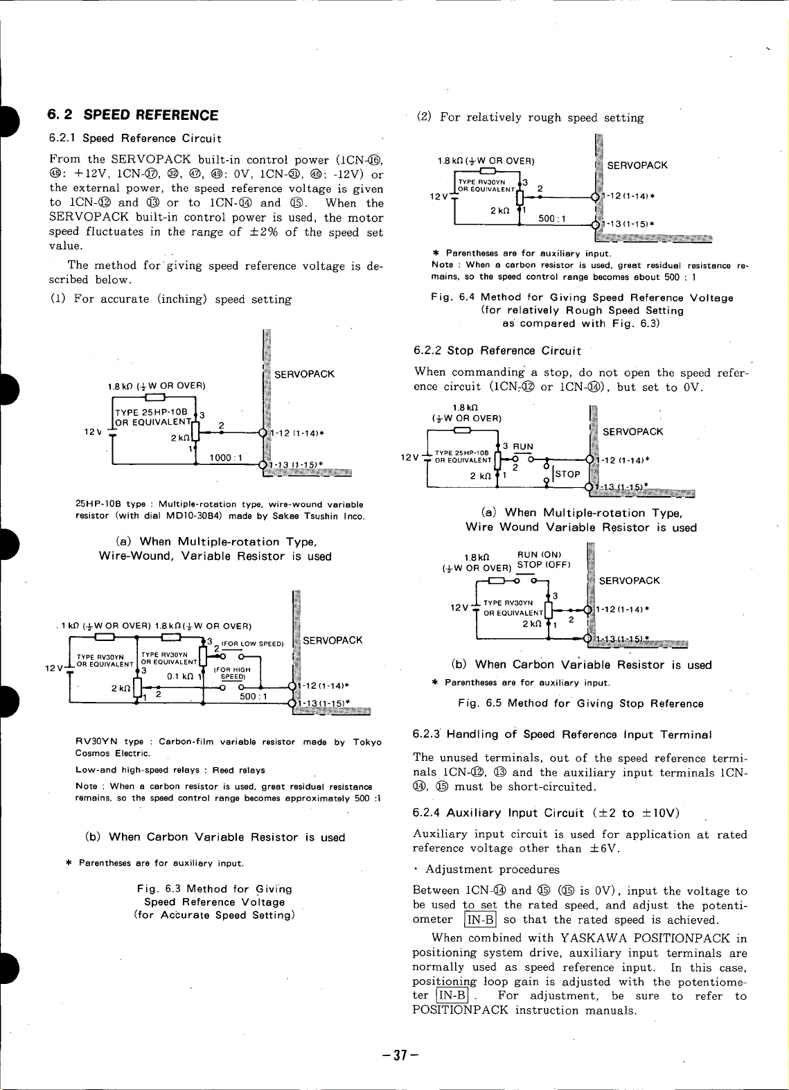
I 6. 2 SPEED REFERENCE (2) For relatively rough speed setting
D t8kO (-}WOROVER) ence circuit (1CN:(_ or 1CN-(_)), but set to 0V.
6.2.1 Speed Reference Circuit
From the SERVOPACK built-in control power (1CN-_, 1.8k£Z(_W OR OVER) _ SERVOPACK
@: +12V, 1CN-@, @, @, @: 0V, 1CN-@, @: -lZV) or ,,,._.v_u_Y. ,o1^
the external power, the speed reference voltage is given A.oREQUIVALENTS,2 !_1N'-12
to 1CN-@ and @ or to 1CN-(_ and (_. When the / 2k_ _1 |_
SERVOPACK built-in control power is used, the motor / 1 500:1 _ 1-13(1-15)*
speed fluctuates in the range of +2% of the speed set _ ..... _ ..............................
value.
The method for giving speed reference voltage is de- Note : When a carbon resistor is used, great residual resistance re-
scribed below, mains, so the speedcontrol range becomesabout 500 : ]
(1) For accurate (inching) speed setting Fig. 6.4 Method for Giving Speed Reference Voltage
SERVOPACK When commanding a stop, do not open the speed refer-
r---1
12V
ioTYPE 25 HP-10BTt 1-12 (1-14)* 1.8ka " ,_:_ •
R EQUIVALEN = 2 I t_l t _?_SERVOPACK
a (+w OROVER) ._
12VT U : :
_ Parenthesesare for auxiliary input.
(for relatively Rough Speed Setting
as compared with Fig. 6.3)
6.2.2 Stop Reference Circuit
/ RUN
T
' _ 1000 l_V J'- TYPE 25HP'10B r_l ----'" Jc'_
25HP-]0B type : Multiple-rotation type, wire-wound variable
resistor (with dial MD]0-30B4) made by Sakae Tsushin Inco. (a) When Multiple-rotation Type,
(a)
D 1.8k_ RUN (ON) _ "
Wire-Wound, Variable Resistor is used
When
Multiple-rotation
Type,
LC "I"OR EQUWALENT _ _ C ._ _'12 (I'14)*
L l _' ._'t3"1-1_*
Wire Wound Variable Resistor is used
, w OR OVER STOP (OFF) [_
r_EC3_o o_1 _ SERVOPACK
(1-14)*
12V LTYPE RV30YN1_3 l_ 1 .
T OREQUIVALENT_ "12(1-14)
l 2k_ Y_ 2 i_,
, (+wOROVER)1, "(WOROVER) / ....!'
I _ rt132 (FOR Low sPEED) SERVOPACK
TYPE RV3OYN TYPE RV3OYN
_J_OR EQRuVv30YIALENNJTYPEEQRU_30_IUIvAOR EQUIVALENTL_ O--_ (b) When Carbon Variable Resistor is used
12v 13 _ ill (FOR HIGH I
T Ollk II SPEEd)].
D l 2k_I-L_- 2 , _ - ( -12(1-14)* _ Parenthesesare for auxiliary input.
D positioning system drive, auxiliary input terminals are
• l_1 L " 1 500:1 _ *
RV30YN type : Carbon-film variable resistor made by Tokyo
Cosmos Electric. The unused terminals, out of the speed reference termi-
Low-and high-speed relays : Reed relays nals ICN-@, @ and the auxiliary input terminals 1CN-
Note : When a carbon resistor is used, great residual resistance (_, @ must be short-circuited.
remains, so the speed control range becomesapproximately 500:1
(b) When Carbon Variable Resistor is used Auxiliary input circuit is used for application at rated
• Parentheses are for auxiliary input. " Adjustment procedures
Fig. 6.3 Method for Givrng Between 1CN-@ and @ (@ is 0V), input the voltage to
Speed Reference Voltage be used to set the rated speed, and adjust the potenti-
(for
Accurate
Speed
Setting)
it-13(1-15) Fig. 6.5 Method for Giving Stop Reference
6.2.3 Handling of Speed Reference Input Terminal
6.2.4 Auxiliary Input Circuit (+2 to _+10V)
reference voltage other than --+6V.
ometer _B] so that the rated speed is achieved.
When combined with YASKAWA POSITIONPACK in
normally used as speed reference input. In this case,
positioning loop gain is adjusted with the potentiome-
ter IIN-BI. For adjustment, be sure to refer to
POSITIONPACK instruction manuals.
-37-
Page 39

6. 3 EXTERNAL CURRENT LIMIT REFERENCE •
CIRCUIT [P-CL, N-CL]
Current can be limited from the outside as well as
within SERVOPACK. The external current limit is 300 /
used for the following "cases:
• To protect the motor from overloading current when
an abnormal load lock occurs in the load.
• To change the current limit value according to the ex- CUR R ENT
ternal sequence. RATIO
The current can be limited by multi-stage setting by (%)
the use of relays (Fig. 6.6). The same effect can be ob-
tained by giving voltage signals making analog change.
2oo
100
/
I
CONTINUOUS
_ _ I SETVOLTAGE(V)
_'1 i_ SERVOPACK
VOLTAGECONSTANTf!_]_ f _ _1-44 (a) Current Limit at Forward Side
• SUPPLY+; '_
L__.J
Relay:Low levelrelay
Fig. 6.6 Multi-stage Switching of
Current Value at Forward Side
6.3.1 Method of Giving External Current CURRENT
Limit Reference (%)
Forward current and reverse current can be controlled 100
independently. The forward current can be controlled
by giving a reverse voltage (0 to --9.0 V) between
SERVOPACK terminals 1CN-@ and @; the reverse cur-
rent can be controlled by a forward voltage (0 to
+9.0V) between terminals 1CN-@ and @. 0 (APPROX_3 6 9
The relation between the rated current of the motor SETVOLTAGE(V)
and applicable motor. The power supply must use an
internal resistance less than 2k12. The input resistance (b) Current Limit at Reverse Side
at SERVOPACKside must be greater than 5kl2. When •
external current is not restricted, contacts between ter- Note : If settingvalue exceedsmax output current value of
minals 1CN-@ and @ and between 1CN-and O and @ SERVOPACK,maxoutputcurrentvaluebecomessaturationvalue.
are opened.
CONTINUOUS 2o0
RATIO
Fig. 6.7 Set Voltage and Current Limit Values
0 [APPROX%--3 --6 --9
300
\ 0.6V)
q
6.3.2 Set Voltage and Current Limit Values
The relationship between set voltages of 0 to +-9.0V
and current limit values are shown in Fig. 6.7.
6.3.3 Current Limit when Motor is Locked
When locking a motor by applying a current limit, de-
termine a current limit value less than 70% of the
rated current of the motor. If the load condition re-
quires a current limit exceeding the rated motor cur-
rent, refer to Par. 6.5. (3), "Overload detection level"
and make sure to unlock the motor before reaching the
trip level.
Note that when the speed reference voltage is less
than tens or so millivolts (affected by setting of GAIN •
of VR4, VR6 and SW3), the motor lock current some-
times pulsates. If this is not desirable, the current pul-
sation can be removed by increasing the speed reference
voltage.
-38-
Page 40

D 6.4 CONFIGURATION OF INPUT/OUTPUT NOTE
CIRCUITS When the overtravel prevention circuit is not used,
connect 1CN-_ and @ to the OV terminal of the
external 24V power supply.
For proportional drive, overtravel, servoON, servo
alarm output, current limit detection output and TG (3) Servo ON [S-ON]
ON output, each input/output circuit is a non-contact
circuit insulated with optical couplers. The external .This circuit is used to turn ON the main-circuit power-
circuit, therefore, must be constructed with the speci- drive circuit of the SERVOPACK. When the signal of
fied voltage and current, the circuit is not input (Servo OFF status),the motor
cannot be driven. If this signal is applied during motor
6.4.1 Input Circuit running, the motor will coast to a stop. Never stop
There are four types of protective functions to prevent motor running.
the motor using Servo OFF except in emergency during
continued rotation of the motor in forward, and re-
verse direction: Servo ON, proportional drive, and NOTE
overtravel prevention (forward and reverse). Construct Before turning power ON or OFF, turn OFF the
the input circuit using 24V power supply (Fig. 6.8). "Servo-ON" switch to avoid troubles resulting
D Typical circuits are shown in Fig. 5.3. from transient current.
6.4.2 Output Circuit
NOTE. There are six output signals: Current limit detection,
TG ON, Servo alarm, Servo ready, MCCB trip and OL
The user must provide the 24V power supply: alarm.
24VDC+lV, 20mA or more (approx 5mA/circuit) These output circuits are non-contact, employing
transistors. Voltage and current specifications are:
Applied Voltage (Vmax) <30V
+24V l PHOTOCOUPLER
D t I r-_ _ ConductionCurrent(Ip)__iOOma
__1 NOTE
0v
-.m---- 5rnA
The output circuit requires a separate power sup-
ply. It is recommended to use the same 24V
power supply used for the input circuit (Fig. 6.9).
Fig. 6.8 Configuration of Input/Output Circuits
D I SERVOPACK OPTICAL • CURRENT
(1) Proportional Drive Reference [P-CON] 24 V 4 _ IVrnax<'. _ + _-_-_-_ " SERvoALARM
If a position loop is not set for positioning, and / T READY
after completion of positioning, has been left for FLY-WHEELDIODE .MCCBTRLP
OUTPUT , COUPLER LIMIT OUTPUT
RELAY _ _ Ip TRANSISTOR 1 • TG ON
quite a long time, the positioned point may have .OLALARM
moved due to preamplifier drift. To avoid this,
switch the speed amplifier from PI drive to P drive
after the positioning and the loop gain in the con- Fig. 6.9 Output Circuit
trol system drops and the drift decreases. With
several percent of friction load, the motor stops
completely.
(2) Forward and reverse running prohibit [P-©T,
N-OT]
- - .SERVO
These circuits are used to stop the forward running
of the motor (counterclockwise when viewed from
the drive end of the motor) and reverse running.
motor. Therefore, the motor • will coast to a stop.
If braking is required, set the speed reference volt-
age to 0V or set the dynamic braking circuit from
OFF to ON.
D This circuit stops output current to drive the
I -39-
Page 41

6.4.3 Optical Encoder (PG) Output Circuit (3) Output phase •
[PAO, * PAO, PBO, *PBO, PCO, * PCO]
Phases A, B, and C (original point) signals for the op-
tical eneoder, PG are output. B q [_ [mE PHASE_[--_ _ r-
Use these signals as positioning signals. The output s
signal specifications are as follows : c c --
(1) Signal form Note : Phase C (original point pulse) is synchronizedwith phase A.
• Two-phase pulse with 90° pulse difference Fig. 6.11 Output Phase
(phases A and B)
• Original point pulse (phase C)
(2) Output circuit and receiver circuit
Two types of output circuits are provided : line driver into 1/N (N=I to 64) or 2/N (N=2 to 64) by using
output and open collector output (SN74LS07N). the divider in the SERVOPACK. The phase relation is
Fig.6.10
shows
an
example
PHASE A
line
of
driver
output.
:C (11C,21C)SN75115
"+5V
LINE RECEIVER waveform under the dividing pulse frequency.
PHASE PHASE__
FORWARD RUNNING REVERSERUNNING
A L__F-q F- A 1 _ I
PHASE }-_490" l-_ 90"
PHASE I I , PHASE ] I '
(4) Pulse resolution
The pulse frequency of the PG can be further divided
the same as in (3), above. Set the pulse frequency di- •
viding ratio according to Table 6.l.
The dividing ratio must be able to divide the pulses
of the optical encoder. For example, in an optical en-
coder of 5000 pulses/rev, 1/3, i/6, or I/7 cannot be
used. Fig. 6.12 shows the optical encoder output
,din
1
Jm
PHASE -- PHASEB (ORIGINALPOINT)
-+5V PHASEA DIVIDING
PHASE PHASEC PHASEB J_J_J_J_J_J_J_ RATIO:1/1
OUTPUT C
TIMC3487 PHASEA FREQUENCY
..NE0R,VER I----I I PULSE
100TO1000PF FREQUENCY
FILTERCONDENSER(C) PHASEC_ I PULSE
DIVIDING
PHASEB_ I-----1 [--q I'-- RAT.O:,.2
PHASEA _ PULSE
0V ! _ F---- "_FREQUE.CY
SERVOPACK REOE,V.E.C,ROU'T
P_: Twistedpairwires. Optical Encoder
Fig. 6.10 Line Driver Output Circuit
(SUPPLIED BY USER)
PHASE B q _ I--"1"1[I RATIO: 113
Fig. 6.12 Output Waveform of
DIVIDING
J
I
-40-
Page 42

I 6.4.3 Optical Er_coder (PG) Output Circuit [PAO, _PAO, PBO _PBO, PCO, ,I,PCO] (Conrd)
Table 6.1 Setting of PG Pulse Frequency Dividing Ratio
SW2 Pulse Frequency Dividing Output
1 2 3 4 5 6 7 8 PG Pulse Frequency PG=6000 PG=5000 PG=4000 lpG=2500 PG=1500 PG=looo
0 0 0 0 0 0 0 0 1/1. 6000 5000 4000 2500 1500 1000
0 0 0 0 0 0 0 1/2 3000 2500 2000 1250 750 500
0 0 0 0 0 0 0 1/3 2000 -- -- -- 500 --
0 0 0 0 0 0 1/4 1500 1250 1000 625 375 250
0 0 "0 0 0 0 0 1/5 1200 1000 800 500 300 200
0 0 .0 0 0 0 1/6 1000 -- " . -- . 250
0 0 0 0 0 1/8 750 625 500 .... 125
0 0 0 0 0 0 1/10 600 500 400 250 150 100
0 0 0 0 0 1/12 500 ..... 125 --
Oi 0 0 0 0 1/15 400 ..... 100 --
I 0 0 0 0 1/16 375 250 ......
I 0 0 0 0 0 0 2/3 4000 ........ . 1000 , --
0 0 00. 0 1/20 300 250 200 125 75 50
0 0 0 0 1/24 250 ..........
Oi 0 0 0 0 0 1/25 240 200 160 100 60 40
0 0 0 0 1/30 200 ' 50 --
0 0 0 0 1/40 150 125 100 ..... 25
0 0 0 1/48 125 ....... " -- ' --
0 0 0 0 0 1/50 120 100 80 50 30 20
0 0 0 1/60 100 ....... 25 • -- "
0 0 0 0 0 0 2/2 6000 5000 4000 • 2500 1500 1000
0 0 0 0 0 2/4 3000 2500 2000 1250 750. 500
© © © © © © 2/5 2400 2000 1600 1000 600 400
0 0 0 0 0 2/6 2000 ..... 500 . --
0 0 0 0 2/8 1500 1250 1000 625 -- 250
0 0 0 0 0 2/10 1200 1000 800 500 300 200
0 0 0 0 2/12 1000 ..... 250 . --
0 0 0 0 2/1 5 800 ..... 200 . --
0 0 0 2,/16 750 "--- 500 -- -- .125
0 0 0 0 2/20 600 500 400 250 150 100
0 0 0 2/24 500 -- -- -- 125
Dividing Ratio (l/N)
(pulses/rev)
t 0 0 0 0 0 2/25 480 400 320 200 120 80
0 0 0 2/30 400 -- -- -- 1O0 --
© © © 2/40 300 250 200 125 75 50
0 0 2/48 250 ....
0 0 0 0 2/50 240 200 160 100 60 40 .
0 0 2/60 200 -- -- -- 50 --
Spare -•
-41 -
J
Page 43

6.5 PROTECTIVE CIRCUIT (3) Servo alarm output [ALM+, ALM-] I
If any trouble detection circuits in Table 6.2 functions,
SERVOPACK provides functions to protect the body the power drive circuit in the SERVOPACK goes OFF,
and motor from malfunctions. 7-segments LED indicate the operation condition and a
(1) Dynamic brake function servo alarm signal is output.
SERVOPACK incorporates a dynamic brake for emer- (4) Protective circuit operation
gency stop. This brake operates when:
Alarm (fault detection) occurs, cause and correct the trouble, and restart the operation.
• Servo ON command is opened. Before checking the cause, turn OFF the power to the
• Main power supply is tuned OFF. that the alarm signal turns OFF only the main circuit
Normally, this dynamic brake is not applied while the (@, @, (2)), as shown in Figs. 6.1 and 6.2. This allows
motor stops, but can operate by switching built-in rapid reaction in the event of a malfunction.
switch (SW 4-5) from OFF to ON. Use this function If the power to the control circuit (@, @) is simul-
only in emergency. Don't use the dynamic brake to taneously turned OFF, this also turns OFF the LED in
stop the motor normally, the SERVOPACK indicating the cause of the alarm sig-
(2)Troubledetectingfunctions nal. I
Table 6.2 Fault Detecting Functions CAUTION
Trouble Detection
Overcurrent flow in the main circuit ing power to the main circuit to resume the
Overcurrent (at 1.2 times min. inst max current.) operation.
Circuit Protector Circuit protecter tripped (5) Resetting servo alarm
Trip
Regeneration Regenerative circuit not activated in pushbutton switch) on the printed circuit board in •
Trouble SERVOPACK. the SERVOPACK.
An alarm signal indicates some trouble. Check the
main circuit to avoid danger. Apply the sequence so
When an alarm signal cuts off only the main cir-
cuit, set the speed reference to 0V before supply-
To reset the servo alarm, press the _ (blue
Overvoltage main circuit (approx 420V.) loaded or the heat sink is overheated), the reset
• Overspeed input, later.
Voltage Drop after power ON. (150V or less.)
Overload Overload condition of motor and
Heat Sink Overheat of heat sink
Overheat (approx 85°C min.)
A/D Error board of SERVOPACK.
Open Phase
Overrun Wrong wiring of motor circuit or PG
Prevention signal line.
CPU Error Any error of CPU
Excessively high DC voltage in the If [_] or [_] is ON (e.g., SERVOPACK is over-
Excessively large speed reference
Low DC voltage in the main circuit
SERVOPACK.
Element error on the printed circuit
Any one phase open in three-phase
power supply.
alarm is not immediate and occurs a few minutes
I
-42 -
Page 44
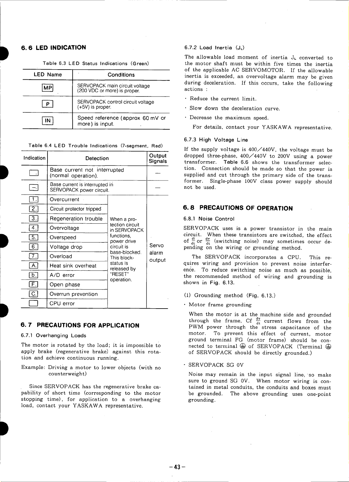
D 6.6 LED INDICATION 6.7.2 Load Inertia (JL)
The allowable load moment of inertia JL converted to
Table 6.3 LED Status Indications (Green) the motor shaft must be within five times the inertia
of the applicable AC SERVOMOTOR. If the allowable
LED Name Conditions inertia is exceeded, an overvoltage alarm may be given
during deceleration. If this occurs, take the following
r_ SERVOPACK main circuit voltage
(200 VDC or more) is proper, actions :
• Reduce the current limit.
_-_ SERVOPACK control circuit voltage
(+5V)isproper. • Slow down the deceleration curve.
Speed reference (approx 60 mV or • Decrease the maximum speed.
more) is input. For details, contact your YASKAWA representative.
Table 6.4 LED Trouble Indications (7-segment, Red)
Indication Detection Output dropped three-phase, 400/440V to 200V using a power
Signals transformer. Table 6.6 shows the transformer selec-
If the supply voltage is 400/440V, the voltage must be
_-_ (normal operation), supplied and cut through the primary side of the trans-
former. Single-phase 100V class power supply should
6.7.3 High Voltage Line
Base current is interrupted in not be used.
SERVOPACK power circuit.
D r-_ Base current not interrupted tion. Connection should be made so that the power is
[-_ Overcurrent
_] Circuit protectortripped 6. 8 PRECAUTIONS OF OPERATION
[-_ Regeneration trouble When a pro- 6.8.1 Noise Control
tectioncircuit
Overvoltage inSERVOPACK SERVOPACK uses is a power transistor in the main
D r_ Overspeed functions, circuit. When these transistors are switched, the effect
r-_ Voltage drop circuit is Servo pending on the wiring or grounding method.
power drive of _ or _ (switching noise) may sometimes occur de-
base-blocked, alarm
di dv
[-_ Overload Thisblock- The SERVOPACK incorporates a CPU. This re-
r-_ Heat sink overheat status is output quires wiring and provision to prevent noise interfer-
released by ence. To reduce switching noise as much as possible,
A/D error "RESET" the recommended method of wiring and grounding is
[-_ Open phase
operation, shown in Fig. 6.13.
[_] Overrun prevention (1) Grounding method (Fig. 6.13.)
D I ] CPUerror • Motor frame grounding
When the motor is at the machine side and grounded
dv
through the frame, Cf _ current flows from the
6, 7 PRECAUTIONS FOR APPLICATION PWM power through the stress capacitance of the
6.7.1 Overhanging Loads motor. To prevent this effect of current, motor
ground terminal FG (motor frame) should be con-
The motor is rotated by the load; it is impossible to nected to terminal @ of SERVOPACK (Terminal
apply brake (regenerative brake) against this rota- of SERVOPACK should be directly grounded.)
tion and achieve continuous running.
Example: Driving a motor to lower objects (with no SERVOPACK SG 0V
counterweight) Noise may remain in the input signal line, so make
sure to ground SG 0V. When motor wiring is con-
Since SERVOPACK has the regenerative brake ca- tained in metal conduits, the conduits and boxes must
pability of short time (corresponding to the motor be grounded. The above grounding uses one-point
stopping time), for application to a overhanging grounding.
load, contact your YASKAWA representative.
-43 -
Page 45

..................... ............................. ..................................................................................... -A
I TYPE
IE 2LF It CACR-SRWl ICi
iBi :,
IP 1 I,.-..i
[ 1
• OPERATING RELAY
I SEQUENCE 3.5ram2 ,
• USER SIGNAL LARGER "
GENERATING
CIRCUIT I
I
'
L
P
3.5mm2
OR
LARGER
2mm2ORLARGER
i FRAME FRAME 3.5mm2ORLARGER/
I LRAD0F FRAMEr_ / I
i 3.5mr_ORLARGER 7_ \ /i
............................................................................ :.............._'_:Fat,ME-._ _i_ ...........................................
]_ : Twistedpair wires _ ONEPOINTGROUNDING
Notes
]. Use wires of 3.5m_]or larger for grounding to the case (preferably flat-woven
copper wire). Fig. 6.13 Grounding Method
2. Connectlinefiltersobservingthe precautionsas shownin (2), "Noisefilter installation"
(2) Noisefilter installation I
When noise filters are installed to prevent noise from
the power line, the block type must be used. The rec-
ommended noise filters are shown in Table 6.5. The
power supply to peripherals also needs noise filters.
NOTE
_ PANEL GROUNDING
|
If the noise filter connection is wrong, the effect (a) Separate the input and output leads. Do not bun-
decreases greatly. Observing the precautions, dle or run them in the same duct.
carefully connect them as shown in Figs. 6.14 to
SERVOPACK Applicable Recommended Noise Filter I_
Table 6.5 Recommended Noise Filter
6.17. _ ___
TypeCACR- Noise Filter Type Specifications BOX BOX I
SRO3BB LF-305 200VACclass,5A II i _
SR07BB _ LF-310 200VAC class, 10A I_
SRIOBB LF-315 Three-phase
SR1EBB CORRECT 200 VAC class, 15 A
SRO5BB_ BOX_
SR20BB LF-320 200VAC class,20 A SEPARATECIRCUITS
SR30BB LF-330 200 VAC class, 30 A
SR44BB _ LF-340 200VAC class,40A Fig. 6.14
SR6OBB LF-350 Three-phase
Note: Noise filter made by Tokin Corp.
I
WRONG t
Three-phase
Three-phase
Three-phase _ /"
Three-phase
Three-phase WRONG CORRECT
200 VAC class, 50 A
I
-44 -
I
Page 46

(b) Do not bundle the ground lead with the filter out- 6.8.2 Power Line Protection
put line or other signal lines or run them in the
same duct. The SERVOP/_CK is operated through the commercial
power line (200V). To prevent the power line accidents
due to grounding error, contact error, or to protect the
_F't-TERF'] [ system from a fire, circuit breakers (MCCB) or fuses
I must be installed according to the number of
SERVOPACKS used (Table6.6).
" _ A fast blow fuse cannot be used, because of the in-
._ rush current.
BOX BOX Table 6.6 Power Supply Capacity and
WRONG CORRECT MCCB or Fuse Capacity
Fig. 6.15 SERVOPACK Power Capacity*• Current Capacity per
TypeCACR- per SERVOPACK MCCB or Fuse
(c) Connect the ground lead singly to the box or the SR03BB 0.65 kVA 5 A
ground panel. SR05BB 1.1kVA 5A
SR10BB 2.1 kVA 8 A
I:_ SR1 5BB 3.1 kVA 10 A
•, SR30BB 6.0kVA 18A
SR44BB 8.0kVA 24A
SHIELDED
GROUND SHORT I // *Values at rated load.
THICK/ SR60BB 11 kVA 32 A
AND I / J
BOX WRONG BOX CORRECT
*Equipment Fig. 6.16'
6.9 APPLICATION
(d) If the control panel contains the filter, connect the 6.9.1 Connection for Reverse Motor Running
filter ground and the equipment ground to the base If the machine construction requires that the normal
of the control unit. forward reference is used for reverse motor running and
_C_ONTROLPANEL circuit across 2CN-1 and 2CN-7 of connector 2CN for
__ i_ the PC. In this case, change of motor and PG connec-
*Equipment
BOX
Fig. 6.17 Fig. 6.18
the normal reverse reference for forward running, short
tion is not required. For forward reference, frequency
dividing output from SERVOPACK forwards B-phase.
_12CN-1 (OV OF PG)
SHORTED " _
-45 -
Page 47

6.9.2 Speed and Torque Measurement
When an instrument is connected to measure speed and POWERSUPPLY
torque, make the connection as shown in Fig. 6.19, SERVOPACKMAIN OFF [ ON [
using a DC ammeter which is +_ 1 mA (both swing) POWERSUPPLy .1
load at fullscale voltage. SERVOONOFF ON
_,_._ii BRAKERELEASE
_ICN-IO MONITOR (LINING) *2 -- *2 --
iilCN.11 SPEED REFERENCE 0V
_!_ soov
Fig. 6.19 Speed and Torque [-to_[ '
r-n
Measurement .
SERVOPACKCONTROLOFF_ ON [
HOLDINGBRAKE OFF ON 1
MOTORRUNNI
/ I\
200ms t0+t
OR MORE
I /
*6
--200ms TO 10SEC
I
• Torque monitor output (ICN-9): +-3.0v +--10%/100% Fig. 6.20 Brake Timing i_
Speed monitor output (1CN-10):
M, F, D series--+-4.0V __5%/1000r/min Timming
S series---I-2.0V +5%/1000r/min *1 "Servo ON" and the holding brake power
Instrument : DC ammeter which is + 1 mA(both supply can be operated simultaneously.
swing) load at fullscale voltage. *2 It takes a maximum of 180ms from when the
Use ammeter of DCF-6 or DCF-12N by mechanical contact is released. It takes a
Toyo Instrument or equivalent, maximum of 100ms when the brake power
• Example : When an M Series motor (rated speed: supply is OFF.
1000r/min) is used, and speeds are to be *3 More than 200ms must be considered from
measured up to the maximum speed when the brake power supply is ON till
(2000r/min) in both directions, use
+-SV (both swing) DO voltmeter. .4 to shows motor stopping time and is
6.9.3 Application of SERVOMOTORS with Holding
Magnetic Brake J.M(=GD_/4) : Motor moment of inertia
AC SERVOMOTORS with brake is held by the brake (kg "rrf=lb'in's2×10-3)
when it stops operation. Follow the procedures below JL(_GD_./4) : Load moment of inretia
for use. (kg"rrf=Ib'in's2×10-3)
(1) This brake locks st non-magnetization. Therefore, Tp : Motor speed reduction torque (N.m)
turn OFF the brake power supply when the motor TL : Load torque (N-m)
stops. Should the brake work while the motor is run- .5 Turn OFF the brake power supply when the
ning the contact causes excessive abrasion and the brake motor stops. For normal operation, t0+t,
may be defective in shorter period, is approximately 1 to 2 seconds.
(2) The brake has delay time. For operation timing of after the brake power supply is turned
ON/OFF, see Fig. 6.20. OFF.
torque
brake power supply is ON till when
when speed reference is input.
calculated as follows :
t° =0"1047× (Tp+TL)
NM : Motor speed (r/min)
*6 Turn OFF "servo ON" 0.2 to 1.0 second
(JM+JL) ×NM (mS)
1
I
1
-46 -
Page 48

7. INSTALLATION AND WIRING If the AC SERVOMOTOR is subject to excessive
water or oil droplets, protect the motor with a cover.
7.1 RECEIVING The motor can withstand a small amount of splashed
This motor has been put through severe tests at the water or oil.
factory prior to shipment. After unpacking, however
check, and see the following. (3) Environmental conditions
• Its nameplate ratings meet your requirements. Ambient Temperature: 0°(2 to +40°(2
It has sustained no damage during transportation. Storage Temperature: -20°(2 to +60°C
• The output shaft should be hand-rotated freely. Humidity: 20% to 80% RH (non-condensing)
However, motors with holding brake do not rotate.
• Fastening bolts and screws are not loose. True alignment of motor and driven machine is essen-
If any part of the motor is damaged or lost, immedi- life, or shaft and bearing failures.
ately notify us giving full details and nameplate Use flexible couplings for direct drives. The align-
data. ment should be made in accordance with Fig. 7.2.
7.2 INSTALLATION
AC SERVOMOTOR can be installed either horizontally
or vertically.
(1) Before mounting
Wash out anticorrosive paint on shaft extension and
SE VO OZO
flange surface with thinner before connecting the motor
(4) Load coupling
tial to prevent vibration, reduced bearing and coupling
D to the driven machine. See Fig. 7.1.
Fig. 7.1 Anticorrosive Paint to.be Removed (5) Allowable bearing Load
(2) Location box, coupling or pulley• Don't exceed thrust and radial
Use the motor under the following conditions.
• Indoors "
• Free from corrosive and/or explosive gases or liquids
• Ambient temperature: -10 to +40
• Accessible for inspection and cleaning
ANTICORROSIVE
PAINT
386-5
(_) Measure the gap between a straight edge end coupling halves
at four equidistant points of the coupling. Each reading should
not exceed O.03mrn.
(_)Align the shafts.
(_Measure the gap between the coupling faces et four equidistant
points around the coupling rim with e thickness gage. The maxi-
mum variation between any two readings should not exceed
0.03mm.
Fig. 7.2 Alignment of Coupling
Avoid shock to the motor shaft when mounting gear
loads specified in Table 4.1 to 4.3.
-47 -
Page 49
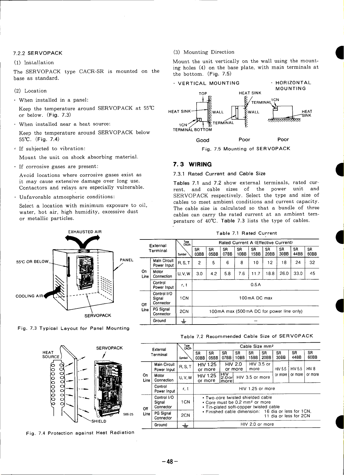
SERVOPACK
7.2.2
(3) MountingDirection •
(i) Installation Mount the unitverticallyon the wall usingthe mount-
ing holes (4) on the base plate, with main terminals at
The SERVOPACK type CACR-SR is mounted on the the bottom. (Fig. 7.5)
base as standard.
• VERTICAL MOUNTING • HORIZONTAL
MOUNTING
(2) Location TOP HEAT SINK
,all
Keep the temperature around SERVOPACK at 55°C
or below. (Fig. 7.3) L- I1_ _ .._ I .._SINK
• When installed near a heat source: 1CN/ _ _ ..... F,
Keep the temperature around SERVOPACK below
HEAT SINK-'-T'-_I_/WALL I II _WALL r-" I HEAT
j2LLr. TERM 'L
TERMINAL BOTTOM
55°C. (Fig. 7.4) Good Poor Poor
' If subjected to vibration: Fig. 7.5 Mounting of SERVOPACK
Mount the unit on shock absorbing material.
• If corrosive gases are present: 7.3 WIRING •
Avoid locations where corrosive gases exist as 7.3.1 Rated Current and Cable Size
it may cause extensive damage over long use. Tables 7.1 and 7.2 show external terminals, rated cur-
Contactors add relays are especially vulnerable.
• Unfavorable atmospheric conditions: SERVOPACK respectively. Select the type and size of
Select a location with minimum exposure to oil,
water, hot air, high humidity, excessive dust
rent, and cable sizes of the power unit and
cables to meet ambient conditions and current capacity.
The cable size is calculated so that a bundle of three
cables can carry the rated current at an ambient tem-
or metallic particles, perature of 40°C. Table 7.3 lists the type of cables.
EXHAUSTED AIR Table 7.1 Rated Current
External CACR-
_ ,_ Terminal SR SR SR SR SR SR SR SR SR
y T_ RatedCurrent A (Effective Current)
55"C OR BELOW_ PANEL Main Circuit R, S, T 2 5 6 8 10 12 18 24 32
i On Motor
" • - Line Connection U,V,W 3.0 4.2 5.8 7.6 11.7 18.8 26.0 33.0 45
' 038B 0EBB 07BB 10BB 15B8 20BB 3OBB 44BB 60BB
/" Power Input
f
1
I
Power Input r, t O.5A
COOLING AIR" Control I/0
.__ Control
SERVOPACK Connector
Fig. 7.3 Typical Layout for Panel Mounting
HEAT SR SR SR SR
SOURCE Terminal
Fig. 7.4 Protection against Heat Radiation
SERVOPACK External T_R_T_R" Cable Size mm 2
/ s_l'_ 03B8 07BB 1S;BB SR SR SR SR
• Signal 1CN • Core must be 0.2 mm 2 or more
586-25 Line PG Signal 2CN • Finished cable dimension: 16 alia or less for 1CN,
SHIELD Connector 11 dia or lessfor 2CN
Signal 1CN 100 mA DC max
Off Connector 9
Line PG Signal 2CN 100mA max (500mA DC for power line only)
Ground __J=L._
Main Circuit R,S, T HIV 1.25 HIV 2.0 HIV 3.5 or
Power Input or more or more more HIV5.5 HIV5.5 HIV8
On Motor U,V,W HIV1.25 HIV ormore ormore ormore
Line Connection or more more
Control
PowerInput r, t HIV 1.25 or more
Control I/0 • Two-core twisted shielded cable
Off Connector • Tin-plated soft-copper twisted cable
Ground _ HIV 2.0 or more
-48-
Table 7.2 Recommended Cable Size of SERVOPACK
0EBB 10BS 20BB 30BB 448B 60B8
2.0or HIV 3.5 or more
Page 50

D Table 7.3 Cable (4) Remedy for Radio Frequency Interference
2.Where cables are bundled or run through a duct (unplasticized
3.Where the ambient (panel inside) temperature is high (40_; to Table 7.4.
Type of Lead Allowable Conductor (R.F.I)
Temperature SERVOPACK may interfere with radio reception. If the
VinylCable (PVC) -- controller interferes with radio reception, connect a
600 V Vinyl Cable (IV) 60 noise filter to power supply.
Special Heat-ResistantCable(HIV) 75 (5) The signal line uses cables whose core is extremely
Notes:
1.For main circuits, use cablesof 600V or more. may damage these cables.
polyvinyl chloride conduit or metalic conduit), selectthe larger 7.3.3 Power LQSS "
cable size than listed considering the current drop rate of the ca-
bles. The power.loss of SERVOPACK is shown in
60°(2), use heat-resistant cables.
fine (0.2 to 0.3m_]). Avoid using excessive force which
7.3.2 Wiring Precautions Table 7.4 Power Loss st Rated Output
SERVOPACK is a device for speed control of 3000:1, SERVOPACK Output
and signal level of several milli-volts or less. Type Current Main Regenerative Control Total
D The following precautions should be taken for wiring. CACR, A Circuit Resistance Circuit
D less). Use central grounding point. If the motor and SR30BB 26.0 160 80 300
D • Run the power line and signal line, holding the dis-
(1) For signal lines and PG feedback lines, use twisted SR03BB 3.0 20 90
cables or multi-core shielded twisted-pair cables 10
(YASKAWA Drawing No. DP8409123 or DE8400093). SR05BB 4.2 4O 110
Cable length is a maximum of 3m for reference input SR07BB 5.8 60 140
lines and a maximum of 20m for PC- feedback lines. SR10BB 7.6 70 20 150
Use the shortest possible length. SR15BB 11.7 80 60 160
(2) For ground line, cable should be as heavy as possi- SR20BB 18.8 100 40 200
ble to provide class 3 ground (ground resistance 101_ or
machine are insulated, ground the motor. SR44BB 33.0 210 100 370
(3) To prevent malfunction due to noise, take the fol- SR60BB 45.0 300 120 480
lowing precautions:
• Place the noise filter, SERVOPACK and I/O refer- Note: The regenerativeresistor causespower losswhen the motor is
ence as near as possible to each other, decelerated,but is negligibleif the motor is not started and stopped
• Make sure to mount a surge absorbing circuit into
the relay, electromagnetic contact, and solenoid coils.
tance to 30cm or more; do not run them in the same
duct or in a bundle.
• When the same power is used for SERVOPACK, as
for an electric welder or electrical discharge machine
or when a high-frequency noise source is present in
the vicinity, use filters in the power and input cir-
cuits.
frequently.
W W W W
Power Loss
• The SERVOPACK uses a switching amplifier, and
electrical noise may be present in the signal line.
Never leave the termination of the analog input wir-
ing open.
-49 -
Page 51
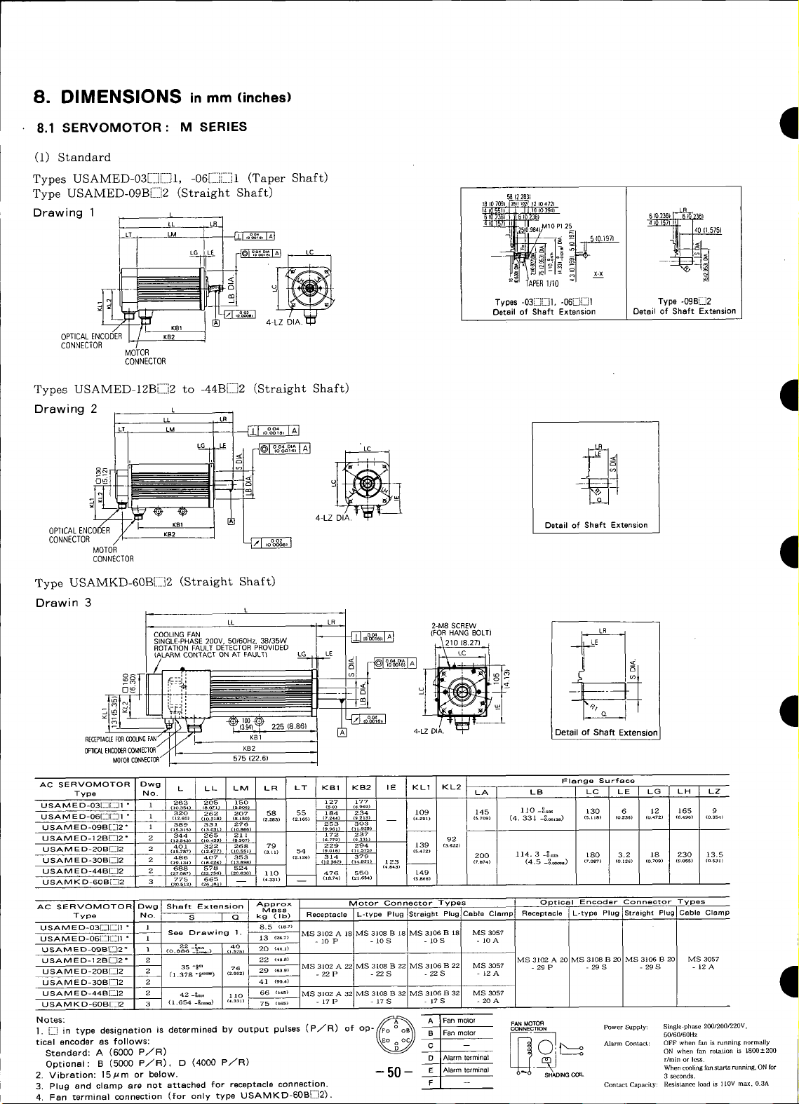
8. DIMENSIONS in mm (inches)
8.1 SERVOMOTOR : M SERIES
(i) Standard
Types USAMED-03[]][]]I, -06[i]][]]1 (Taper Shaft)
Type USAMED-09B[]]2 (Straight Shaft) _(22831
LL L M10 P1 25
1810709) _ Jl 104721
6102361 610236) 6 _O236) _ I
Drawing 1 U ]4_055._0(e_4) L_
- /_Y[tl I/IU
OPTICAL ENCODER KB2
CONNECTOR
TypesUSAMED-12B[]]2to -44B[]]2(Straight Shaft) I
Drawing 2 L
/ KBI
_[_ -.__ Types-o3E]"_-]I._-"_l Type-09m.:i2
MOTOR
CONNECTOR
LL
LM
LG " LC LR
4-LZ DIA. qJ
u
J
Detail of Shaft Extension Detail of Shaft Extension
"VUL.._J
OPTICAL ENCODER I_ KB1 Detail of Shaft Extension
MOTOR
CONNECTOR I
CONNECTOR
KB2
4-LZ
Type USAMKD-60B[[]2 (Straight Shaft)
Drawin 3
2-M8 SCREW
(FORHANGBOLTi L_ 1
D_
RECEPTACLEFORC(]OUNGFAN/
575 (22.6)
AC SERVOMOTOR Dwg L LL LM LR LT KB1 KB2 IE KL1 KL2
Type NO. LA LB LC LE LG LH LZ
U SA M E D-03[]..][[-]1 ° 1 263 205 150 )'27 177
U SA a E D-O6[_JE[I1
USAM E D-O9B[I:]2 * 1 389 331 276 253 303
USAMED-I 2BE]2* 2 344 265 211 172 237 I
USAM E D-20BE_]2
U SAM E D-3OB[:_J2 2 486 407 353 (zlzo) 314 379 200 114. 3 -o°ozs 180 3.2 18 230 13.5
USAM E D-44BL]2 2 688 578 524 (4_3)
USAMKD-6OB["]2 3 775 605 -- I (4zal) __ (,a._) (=_._) (sa_)
AC SERVOMOTOR Dwg Shaft Extension Approx Motor Connector Types Optical Encoder Connector Types
Type No. S I Q kg ( I b) Receptacle L-type Plug Straight Plug Cable Clamp I Receptacle L-type Plug i Straight Plug I Cable Clam¢
USAMED-03[:E][[]] * 1 See Drawing I. 8.5 MS 3102 A 18 MS 3108 B 1_ MS 3106 B 181 MS 3057
USAMED-06E-][_]I ° 1 13 {zs_) - 10 P - 10 S - lOS I - 10 A
USAMED-O ,__-_. " 1 22 _&_= (40)
USAMED-12B[:]]2* 2 22 (4s_) MS3102A20 MS3108B20 MS3106B20 MS3057
USAM E D-30B[]]2 2 41 (_o.a)
USAMED-44BE_]2 2 42-_o_ 66 (_aa) IVIS3102A32 vIS3108B32 MS3106B32 MS3057
USAM KD-60BE]2 3 (1.654 -R,_) (_.ss_) 75 ('_) - 17 P - 17 S - 17 S - 20 A
(,o3s4) (aOTl> (s_oo (so) (_969)
1
320 262 207 z.28358 (55) 184 234 109 145 110 -8o_s 130236 ( 12 I 165 ( 9
(l=_O) oo.sls) (a.Lso) (.) 2.1es _z44) (9_Is) __ (4.2_i) (sToa) (4. 331 -_,_) (s.lla) (0 6) 0472 (6496} 0354
2
401 3_2 268 (79) 229 _94 139 (a_z_)
(19._3_) (I_.OZ4) (13 89a} (12 3e2) (14 921z 123 __ (1ul_) (4.5 _o ) (7 o8_) (o _g6) (o 1o9) (9 o55) (o531)
(z_oa_) (zz._s_) (zest) _ 110 476 550 /49
Mass
35*8°_ (76) 29 (63_) MS3102A22 _[$3108B22 MS3106B22 MS3057 -29P -295 -295 -12AUSAM E D-2OBE]]]2 2 (1.378 *P) z_oz - 22 P - 22 S - 22 S - 12 A
110
4-LZ DIA. Detail of Shaft Extension
Flange Surface
)
I
1. []]] in type designation is determined by output pulses (P_R) of op- Power Supply: Single-phase 200/200/220v,
tical ancoder as follows: Alarm ContacL: OFF when fan is running normally
Standard: A (6000 P/R) ON when fan rotation is 1800+-200
Optional : B (5000 P/R), D (4000 P/R) D Alarm terminat r/Tin or less.
2. Vibration: 15Fro or below. --50-- Alarm terminal v--v- SHADING COIL 3seconds.
a otasl @ ; I FaR m010r CONNECTIONFAN_TO_ _
3. Plug and clamp are not attached for receptacle connection. ConLact Capacit.y: Resistance load is ll0V max, 0.3A
4. Fan terminal connection (for only type USAMKD-60B[_]2).
B Fan motor 5O/6O/60Hz
When ccol_ fan starts rurmLqg, ON for
Page 52

I (2) With Brake
Types USAMED-03[II]i:::]IOE, -06iii:]i:_:]lOE (Taper Shaft)
Type USAMED-09B[:::]2OE(Straight Shaft)
Drawing
1
OPTICAL
CONNECTOR K82
ENCODER
L 58{22831
MOTOR
CONNECTOR
Jl. KB1 [_ -- 4-LZ DIAL_ Types -03'_D1OE, -06,'BDIOE Type -09B_20E
LR 18I,709} 12_04?2)
LG LE" '25_1 40(15751
Detail of Shaft Extension Detail of Shaft Extension
Types USAMED-12BEII]2OE to -30B{III]2OE
L
Drawing 2 LL ,R
I 53 LM
0PTICALENCODER
CONNECTOR CONNEC10R {Detailof Shaft Extension
AC SERVOMOTORDwg L LL LM LR LT KBt KB2 IE KL1 KL2
D Ftange Surface Shaft Extension
Type USAMED- No. LA LB LC LE LG LH LZ S Q
06[:][E]10 E ° 1 366 308 253 58 55 280 __ 113 145 110 -:_ 130 6 12 165 9 (o.z_) (L_o=)
0gB(I_]20 E " l {17.]65) ti4._2) (I2717) (13.7_)) 92 {o._ ._._ _L575_
12B[_I2OE 2 422 343 289 315 (3.62z)
2OBE_2OE 2 (tP.t34) (16.e2_.)(taaga) (3._o) _z._t6) (_A57) (l_.9zt) {_.._ _s3o) _ (?._74) (4.S-_) (7.os?) (e._z6_ (o7o9) (g.oss) (o._at) ([.378% _=_) (z.ggz)
30B[_J20 E 2 ! 567 488 434 460
AC SERV0MOTOF Owg Approx Magnetic Brake Connector Types for Mote C and Brake Optical Encoder Connector Types
Type USAMED- No. kg (Ib) W kFl-m' (Ib.in.s') N-m(Ib.in) Receptacle L-typePlug Straight Plug CableClamp Receptacle L-typePlug StreightPlug CabfeClarnp
03DDIOE" 1 _L5
06[_E]10 E " 1 (_a5)
09B[-]2OE ° 1 z3 18 0.9Xl0-' (7.97x10") 8.83 (78.1) A20 - ISP B20 - 15S B20 - ISS - 12A MS 3102 MS 3108 MS 3106 MS 3057
12BF_]2OE 2 30
2OB[_]2OE 2 37 31 625x10" (553x10" 35.3 (312.5)
30B[ZI2OE 2 (,_I
"Not provided with an eyebott,
N ores:
1. Eli in type designation is determined by output 2. Vibration: 15/Zm or below.
pulses (P/R) of optical encoder as follows: 3. Plug and clamp ere not attached for receptacle connection.
Standard: A (6000 P/R) 4. Power supply for brake is 90 VDC.
Optional: B (5000 P/R), D (4000 P/R) 5. For type USAMED-44B_2OB (4.4kW), contact your
320 262 207 128 234
([4+409) (12l[26} (91961 ) (Zl283) (21165) _8 (1| 024) (4.449) (5,709) (4•331 -- _[_) (5 1]8) (0 236) (0-472) (61496) (0'3_)
436 378 323 (4646) 350 22.,=., 40
(16614) (t3504) (t1.318) (12.402)
486 407 353 79 54 164 379 123 143 200 114.3 -_= 180 3.2 18 230 13.5 35 "$°' 76
(_Z323) (10_13) (_7.esT) (_Slm)
Mass Wattage Inertia sm_¢F_ r=._=
(zs.(} 18 0.8SX]0-' (?.SZXl0" 5,88 (52.1) MS 3102 MS 3108 MS 3106 MS 3057
(507)
(e_,) MS 3102 MS 3108 MS 3106 MS 3057 A20 - 29P B20 - 295 B20- 295 - 12A
(Sl._)
49 A24 - 10P B24 - 10S B24 - 10S - 16A
KB_
(3) Shaft Extension of Straight Shaft
4-L
Y ASI< AWA representative.
LR
w_th Keyway AC SERVOMOTOR Type USAMEO- Shaft Extension
Both SERVOMOTORS without brake and Without Brake With Brake LR LE S Q QK T U W
with vrake have the same dimensions -_.
except for. shaft extension. 03D,_2K _r" E -om_ 5 3 5
Sjaft extensions are shown below: 06[]_2K 06_[_J2KE 58 6 (0.748 _¢_,) 40 25 (o.,97) (o.,_s) (o.,_v)
LR 09B_]2K 09B[Z)2K E 22 -0%,= 6 3.5 6
LE... 12B[__}2 K 12BZ_-_I2K E
• W _ 20BD2K 20BE-I2KE 79 35 +_o, 76 60 l0
30B;_]2K 30B[_]2K E 3,2 8 )(oj59_)
_ . _ (0"1Z6) . (0'315)
F-_ _ (_,,[o) (1.378+o _._¢_',) (z._9_)(_.3_z) (o._9_>
"Onlyfor USAMED-03(II]]C_I]2to -09BL..._2
Note: Dimensionsof the shaft extension key and keyway are based on JIS (Japanese Industrial Standard) B 1301
"Sunk Keys end Their Corresponding Keyways (Normal keys)." Shaft extension key is furnished•
'-i
44BE]2K 44B[I_2KB 110 42 -_o,, ]10 90 12
03[_JL_2K 19 o
(2.za3) (0Z362 (LST5) (0984)
(0.866_0°_,) (o,z3_)(o.,_) (o._3_)
(_,3_)' (1.654 _._3) (_.3_)(as_3) Io._?z)
-51 -
Page 53

8.2 SERVOMOTOR: F SERIES I
(I) Standard
14 37(1.457)
Types USAFED-02[III][III]I, -03Ill]LIlt (Taper Shaft) 1055u_aa3151
L _{ _ I 1661023014
Drawing 1 I '"LL,LT LM1LG.71)_ -LE" I _LR __ -- _ __l 0(0.157_<_
4-LZDIA.
OPTICALENCOOER'._ KB2 1 Type -02LqE]I, -03[-]i-31
CONNECTOR //" ' Detail of Shaft Extension
MOTOR
CONNECTOR
Types USAFED-05[II]EII]I, -0911111[][1111111(Taper Shaft)
-I3CEI]2 (Straight Shaft)
Drawing 2 L 56_l.2S31 2811 t021 I
OPTICALENCODER I / KB2 Detail of Shaft Extension Detail of Shaft Extension
CONNECTORMOTORCONNECTOR •
LT LM __ 6(02361 6[02361 0102361_3610102361 6(02361
/ I , Types -05C[[il, -09=J_..1 Type -13CC]2
LL 18{0 7091 103(0406}
' " 25(09841 _ j
4-
;4 ( 12(0472} LR
Types USAFED-20CEI]2 to -44C[II]2 (Straight Shaft)
Drawing 3 L
LT LM
LL LR
LG E "_ LC
I
<
5 _
/ KBI
OPTICALENCOOER KB2
CONNECTOR _ Detail of Shaft Extension
AC SERVOMOTOR Dwg L LL LM LR LT KB1 KB2 IE KL1 KL2 Flange Surface
TypeUSAFED- No. LA LB LC LE LG LH LZ
02E][[[[] 1 1 ......... (3_403) 132 390a _s z_7
03E][[[[]1 1 236 199 159 c_.*sT) (*.sTs, ]36 178 <z.992) <3_zs) (_.937) (3.150-_,,,) ( , co 7) co _) (_.72_) <o.=_)
05 [[]]]IZI 1 ° 2: 263 205 150 127 177
o_i:::::_i:::::,- _ ......... _2_ _L_o ...... _09 _4s ,10 _Oo,o _30 p_ b_ _s _o
1 30E]2 * 2: 389 331 276 253 303
200[[[[]2 " 3 (_3.s43)I (*o43a) (&soT) (_._2a) ¢_.33n
3OOE::]2
44CE]2
AC SERVOMOTOR Owg Shaft Extension Mass
Type USAFEO - No. S Q k£1 (Ib) Receptacle L-type Plug Straight Plug Cable Clamp Receptacle L-type Plug Straight Plug Cable Clamp
02[:II_]E_II I I l.S 15 (_s) ]IS 3102 A 14 S MS 3108 B 14S MS 3106B 14 S MS 3057
03[::::][:::11 1 (o,s_ (o_n <6z) - 2 P - 2 S - 2 S - 6 A
o5[Z::IE:ZI_ 2: <z_) 28 (,,,)
09I::::]EZiI ° 2: (,.,o=) (13) MS 3102 A 18 MS 3108 B 18 MS 3106 B 18 MS 3057
136[:::::]2 ° 2: zz • (20) - 29 P - 29 S - 29 S - 12 A
20C[_]2 " 3 (_) All
440[[[[]2300E]2 33 (1.378 +_') 2992 (94o_)
"Not provided with an eyeball.
Notes:
1. [_] in type designation is determined by output pulses (P/R) of optical encoder as follows:
Standard: A (6000 P/R)
Optional: B (5000 P/R), D(4000 P/R)
2. Vibration: 15_m or below.
3. Plug and clamp ere not attached for reseptacte connection.
3
3
* 8.5
, _
MOTOR
CONNECTOR
(74_) CS.OZ4) C4.449) 37 40 (s.197) -- 76 87 100 80 -_o_ 120 6.6
(9291) (_SaS) (6.2B0) (S.3S4)(7._I)
(lO.3s4> (aoTl) C5.9_) (so) C_._eg)
344 , 265 211 172 237
(401,',.7_7" ...... 79212654 ...... 139 200 114.3 -o°ozs 180 3._ .7og18 230 13.5
(12677) (IO551) (3.11) ( ) <9016, <US?S) 123 (5472) (7"814) (4.S o ) (7087) (o.126) (o. ) c9.o5s) (o53])
(486) :1#134407 353 314 379 (4._3)
Approx Motor Connector Types Optical Encoder Types
-10P -10S -10S -10A MS310ZAZ0 MS3108B20 MS3106B20 MS3057
35+_ _' (76 (29) -22P -22S -22S -IZA
MS 3102 A 22 MS 3108 B 22 MS 3106 B 22 MS 3057
4-LZ DIA. "1-
92
-52-
Page 54
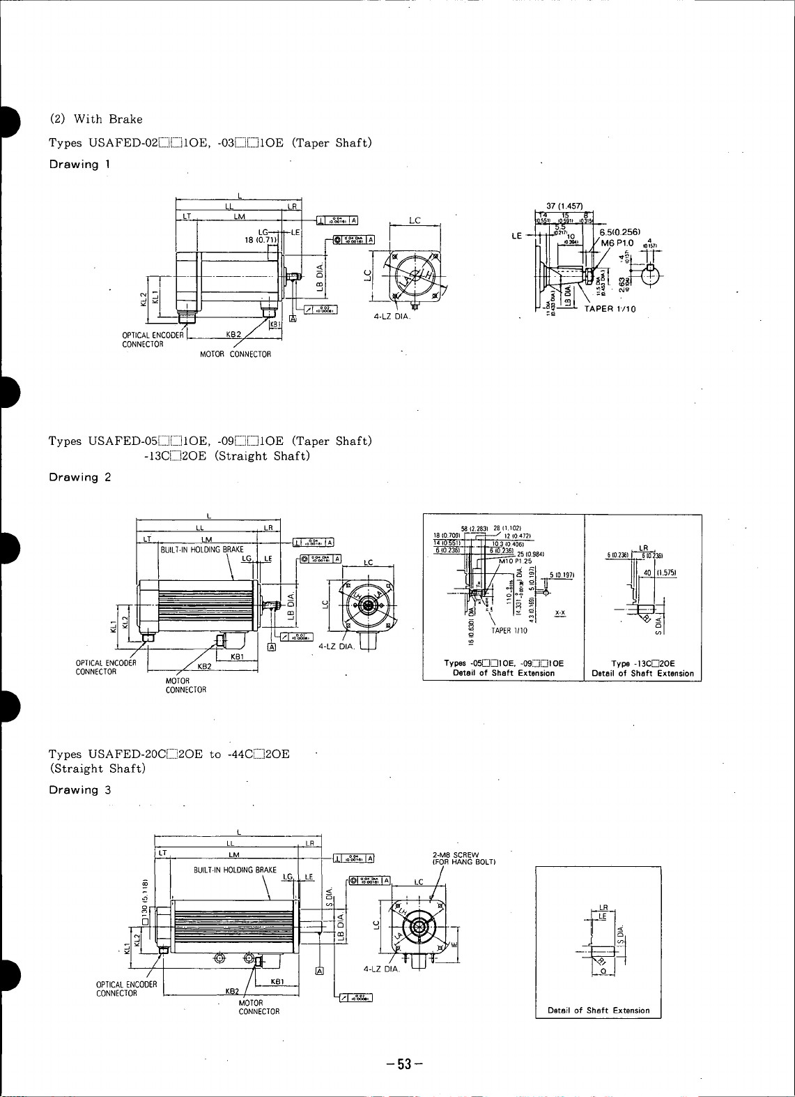
D
(2) With Brake
Types USAFED-02ilIII]EIIilOE, -03[IIII]E]IOE (Taper Shaft)
Drawing 1
L
, ,,,o,,,
I _ Y M6 e]_u ,o,s,,
-- _l " - m
LT LM L_ °"_45.5_°_9",0_,5
OPTICAL ENCOOEBL KS2
CONNECTOR
MOTORCONNECTOR "-
Types USAFED-05[:::I][::::]IOE, -09E:::][::::]IOE (Taper Shaft)
-13CE]2OE (Straight Shaft)
Drawing 2
L
LL LR 58(2.283128(1.102)
HOLDINGBRAKE LR
-- MIO P125i
t _ _ o
4-LZ DIA.
14IO551) 103 IO406)
6 40236) '6 (0236] 25(09841
_ 5 (01971
, ,0236, 6102361
D LT BUILT-IN LM _ _ LE -_ LC 18(0.7091_i 12(0472)_i _ __
_]_ , , _ TAPER1110
OPIICAL ENCODER Types -05.[__L_lDE. -09L_D1 DE Type -13CFq2OE
CONNECTOR Detail of Shaft Extension Detail of Shaft Extension
D CONNECTOR
Types USAFED-20CQ2OE to ;_
MOTOR
-44C_.....,2OE
(Straight Shaft)
Drawing 3
L
LT LM _ 2-MBSCREW
LL LR
(FOR HANG BOLT)
BUILT-INHOLDINGBRAKE LE _C/
5 _
OPnCA[ENCOOER
CONNECTOR _
MOTOR
CONNECTOR Detail of Shaft Extension
-53-
Page 55

I
ACTypeSERVOMOTORusAFED.DWgNo.L LL LM LR LT KB1 KB2 IE KL] KL2 LA LB LC LE LG LH LZ S I Q
O_r"Tr'], 0 E 236 199 159 178
LL..__L__ 1 80 -o%_
03_]L]10E 1 m.290) (9.8o5)(8.228) (s.9751
05l_i[-il OE * 2 320 262 207 128 234
"-- (12.598) (10.3151 (8.1501 (5.039) ! (9213)
09DDIOE* 2 (14.4091u2.,25) (9.9611(2.2_) m65) 118 !(1L0241 (4.445) (S.7O9) (4.331_o°00_) (9.n81 (0.236) (0A72) (6.496)(0.354)
13CD2OE * 2 436 378 323 (4.6461350 22__,,, 40
20C[_-,,'20E* 3 a6.6_41aa._) (u.3n) u24.2)
30C_2OE 3 486 407 353 79 54 164 379 143 200 114.3 -_ 180 3.2 18 230 13.5 35 +oo, 76
44CFq20 E 3 567 488 434 460 (4.8431
-- (Z9.322) (19213). (17.087) (18.110
AC SERVOMOTORDwg Approx Manetic Brake Connector Types for Motor and Brake Optical Encoder Connector Types
TypeUSAMED- No. k,q (Ib) W k9 • m' (Ib.in.s') N.m (Ib.in) Receptacle L-typePlug StraightPlug CableClampReceptacle L-type Plug Straight PlugCableClamp
02[_L-]IOE 1 5 8 0.O75Xl0-' (0.66x]0- 0.98 (8.67) MS 3102 MS 3108 MS 3106 MS 3057(ll.0)
03JIll]leE 1 7 12 0.1]3Xl0-' (l.O0Xl0- 1.96 (17.3) A14S-6P B14S-6S B14S-6S -6A
05r_]Dl O E" 2 11.5
09D_J] OE * 2 i5
13C[-]20E* 2 23 18 o.9xlo-' (7.97x10") 8.83 (78.1) A20-29P B20-29S B20-29S - 12A
20CQ2OE * 3 30
30CD2OE 3 (8L6137 31 625xl0" (55.3x10") 35.3(312.5) A24-10P B24-10S B24-10S - 16 A
44CD2OE 3 49
"Not provided with an eyebolt.
Notes:
1. [i] in type designation is determined by output pulses (P/R) of op- 2. Vibration: 15/zm or below.
tical encoder as follows: 3. Plug and clamp are not attached for receptacle connection.
Standard: A (6000 P/R) 4. Power supply for brake is 90 VDC.
Optional: B (5000 P/R), D (4000 P/R)
(9.291) (7.8_5) (5.290) 37 40 24 7.008) 76 87 100 90 4 7 120 6.6 See Drawing 1.
286 249 209 (L451) (1.575)(0.945);'28 (2.992) (3.4951(3.937) (3.150 -00.00,s) (_._3) (0.1571(0.2761(4.n4) (0.2501
366 308 253 58 55 280 -- 113 145 110-o°=5 130 6 12 165 9 See Drawing 2.
(17.165) (14.8821 (12.717) (13.780) 92 (0.866__,) (L575)
422 343 289 315 (3.5221
(m331 (16.024)(,9.898)(3.no) (z.,z61:(64971 (149ml 123 (3._3o) (7.874) ( 4.5-0o00g_) (7.087) (0.1261(0.709) (9055) (0.531) (1.378+00_) (9.999)
Mass Wattage inertia sat_Fr_0,"_0rqL_
(254) 18 0.85×10-' (7.52x10-') 5.88 (52.1) MS 3102 MS 3108 MS 3106 MS 3057
(15.41 I
(33._) A20-15P B20-15S B20-15S -12A MS 3102 MS 3108 MS 3106 MS 3057
(50.7)
{66.11
(108)
I I Flange Surface Shaft Extension
MS 3102 MS 3108 MS 3106 MS 3057
(3) Shaft Extension of Straight Shaft
I WithoutBrake With Brake S Q OK T U W
with Keyway AC SERVOMOTORType USAFED- Shaft Extension
Both SERVOMOTORS with brake and
without brake have the same dimensions 02DD2K 02DD2KE 37 4 14-o°o,, 25 15
except for shaft extension. 03DWi2K 03DF__2KE (L49n m5n (0.551-g_) (o9_) (o99_) 5 3 5
Shaft extensions are shown below: 057_iD2K 05D[]2KE 19 -oo,3° {o.lm (o.m) (o.1_7)
LR -. 09___D2K 09D[]2KE 58 6 (0.748 -o_,) 40 25
LE 13CD2K I3C_2KE (0.866 _o°_,) {0.2361 {0.138) (0236)
* Q 6 3.5 6
30CD2K 30C.I)2K E 79 3.2 35 +o°°' 76 60 8 5 10
44CD2K 44C.:£)2KE
20C[:[]2K 20C[]2KE
"4 mm (0.157in.) for USAFED-O2[-jF-_]2 end 03_)2
6mm (0.236in.) for USAFED-OSr_-)D2 tO 13C[_-i2
LR LE
o
(9,283} (0.?.36) 22 _o°o_a {1.575) (0.984)
{)'110){OmI2_)(1.378 +)m_ ) (Z'_]Z){Z.362}(0.31S}{0,[97}(Om394)
- 54 -
Page 56
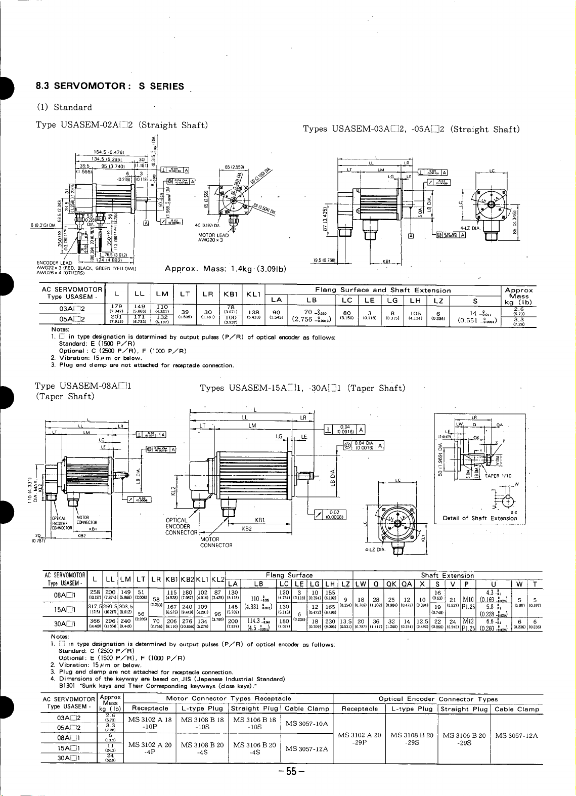
D 8.3 SERVOMOTOR: S SERIES
(1) Standard
Type USASEM-02A[]]2 (Straight Shaft) Types USASEM-03A[]]2, -05A[]]2 (Straight Shaft)
1645 (64761
39.5 95(37401 ' 3 6512.559) _._ -
8103151DIA 4-510
MOTOR LEAD
AWG20 × 3
ENCODERLEAD 195 KB1 .
AWG22x3 {RED,BLACK.GREEN(YELLOW)] Approx. Mass: 1.4kg. 13.091 b)
AWG26 x 4 IOTHERS)
D AC SERVOMOTOR Flang Surface and Shaft Extension Approx
Type USASEM- L LL LM LT LR KB] KL1 LA LB LC LE LG LH LZ S kg (Ib)
03A[]]2 179 149 13.0 78 2.6
05A[[]2 201 171 132 11535) U.lSt) 1OO (s.433) (3.s,3) (2.756 --Oo01z) (3'150) 10"118) 10315) (4"134) (0'236) 10.551 _O0OOO4) 3.3
Notes:
1. []] in type designation is determined by output pulses (P/R) of optical encader as follows:
Standard: E (]500 P/R)
Optional: C (2500 P/R), F (1000 P/R)
2. Vibration: ]5/zm or below.
3. Plug and clamp are not attached for r_eptacle connection.
(7047) (5866) 14.331) 39 30 13.071) 138 90 70 --0030 80 3 8 lOS 6 14 -°el I (5.73)
(7913) (6.732) (5,197) (3.937) (7.28)
L
Type USASEM-08A[]]I Types USASEM-15A[[]I, -30A[]]l (Taper Shaft)
D (Taper Shaft)
I. L
. LL i _ LR _ Le
LT _i _ LM I -L 004 A ,c _ '°A'°A
0006 L_.J_L__L j , "
004 DIA
Mass
!
" I
OPTICAL/ KB1 _ Detail of Shaft Extension
ENCODER KB2-
CONNECTOR
, -
ACTypeSERVOMOTORusASEM_L LL LM LT LR KBI KB2KL] KL2 LA LB LC LEILG LH LZ LW Q QK QA X S V P U W T
08AD1 258 200 149 51 115 180 102 87 ]30 t20 3 i,o1166 16 4.3 _,
15A[]]l
30AL_.Jl
Notes:
l. []] in type designation is determined by output pulses (P/R) of optical encader as follows:
2. Vibration: 15/zm or below.
3. Plug and clamp are not attached for r_eptacle connection.
4. Dimensions of the keyway are based on. JIS (Japanese Industrial Standard)
D AC SERVOMOTOR Approx Motor Connector Types Receptacle Optical Encoder Connector Types
Type USASEM- kg (Ib) Receptacle L-type Plug Straight Plug Cable Clamp Receptacle L-type Plug Straight Plug Cable Clamp
03A [i]] 2 2.6
05A[[]2 (7.28)
08A[[]l a MS 3102A 20 MS 3108 B 20 MS 3106 B 20 MS 3057-12A
I5A[]]I ] ] MS 3102 A 20 MS 3108 B 20 MS 3106 B 20 MS 305%12A -29P -29S -29S
30A[:[:,I _4
11&157}(7.874)(5866)(2008) 58 (4.52_)(7.087)(4.m6) (3.4ZS)(S.tm) II0-_ (4.7Z4)(O.nS)(0.394)(6.fez) 9 18 28 25 12 10 (063) 21 MI0 (0.169-_) 5 5
}17.fi259.5203.5 (2883) 167 240 109 145 (4.3314®,3) 130 12 I 165 (o354)(o7o9) (l.loz) (09_) (o472) (03_) 19 (08z7) PI.2[ 5.84, la,_) (o.L97)
(12.5)((&217)(&012) 56 (6575)(9449)(4891) 96 (S.709) (SAt8) 6 (0.478),!(&496) (0748) (0.228-_0_)
366 296 240 (z.2o5) 70 206 276 134 (3780) 200 114 3-_._ 180 (o.236) 18 1230 13.5 20 36 32 14 12.5 22 24 M12 6.6-_ 6 6
34_) (n_) 19._8 (8.;s_re.no)ao._o)(sz7e 17._) (4.5-_,f_l_(7.087) 1o.7o9)1(9.oos)1o.531)(o787}o.417)1126o)(o350(0492)(0866)(o.945)P1.25 (0.260-_) 102_) (0.8_0
Standard: C (2500 P/R)
Optional: E 11500 P/R). F (1000 P/R)
B1301 "Sunk keys and Their Corresponding keyweys (close keys)."
Mass
(s.7_) MS 3102 A 18 MS 3108 B 18 MS 3106 B 18
3.3 -10P -10S -10S MS 3057-10A
(13.2)
(_.3) -4P -4S -4S
152.9)
MOTOR
CONNECTOR 4-LZ
Flang Surface Shaft Extension
-55-
Page 57
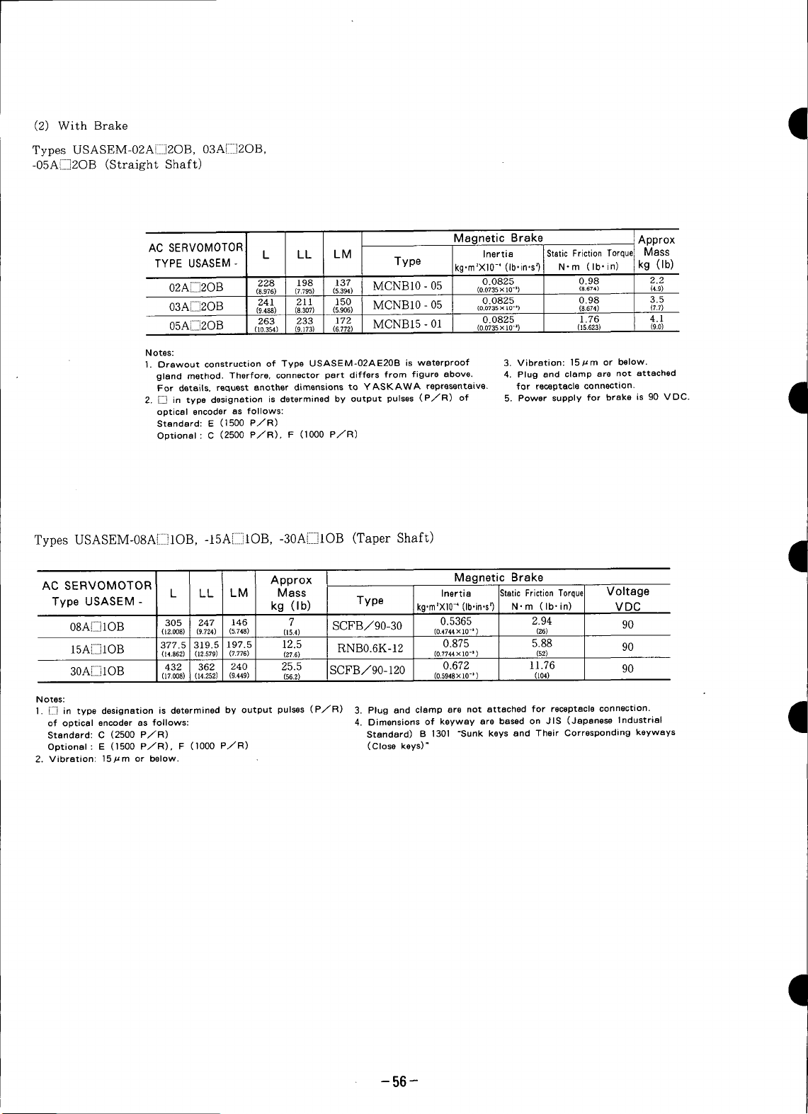
(2) WithBrake •
Types USASEM-02AEIII]2OB, 03A[IIII]2OB,
-05A[IIIIi2OB (Straight Shaft)
AC SERVOMOTOR Magnetic Brake :Approx
TYPE USASEM- L LL LM Type kgorn'X]0 -' (Iboin,s_ N-m (Iboin) I kg (Ib)
02AEIIi2OB 228 198 137 MCNB10 - 05 0.0825 0.98 2.2
• (8.976) (7.795) (5,394) (0.0735 x I0-*) (8.674) (4.9)
03A[III]2OB 241 211 150 MCNBI0 - 05 0.0825 0.98 3.5
- (9.488) (8.307) (5.906) (0.0735x 10-)) (8,674) (7.7)
05A[IIIi2OB 263 233 172 MCNB15 - 0l 0.0825 1.76 4.1
. (lO,354) (9.173) (6.772) (o.o735 x 1o-_) (15,623) (9.0)
Notes:
1. Orawout construction of Type USASEM-02AE20B is waterproof 3. Vibration: 15]zm or below.
gland method. Therfore, connector part differs from figure above. 4. Plug and clamp are not attached
For details, request another dimensions to YASKAWA representaive, for receptacle connection.
2. D in type designation is determined by output pulses (PTR) of 5. Power supply for brake is 90 VDC.
optical encoder as follows:
Standard: E (1500 P JR)
Optional: C (2500 P JR), F (1000 PTR)
Inertia Static Friction T0rquc MaSS
Types USASEM-08A[IIIIilOB, -15AEIII]IOB, -30A[IIII]IOB (Taper Shaft) 9
AC SERVOMOTOR Approx Magnetic Brake
L LL LM Mass Inertia StaticFrictionTorque Voltage
Type USASEM- kg (Ib) Type kg.m'X10_(Ib.in,s_ N.m (Ib-in) VDC
08A[iiiiilOB 305 247 146 7 SCFB/90-30 0.5365 2.94 90
15A[IIIIilOB 377.5 319.5 197.5 12.5 RNB0.6K-12 0.875 5.88 90
30A[IIII]lOB 432 362 24o 25.5 SCFB/90-120 0.672 11.76 90
Notes:
1. [..ii] in type designation is determined by output pulses (P/R) 3. Plug and clamp are not attached for receptacle connection.
of optical encoder as follows: 4. Dimensions of keyway are based on JIS (Japanese Industrial
Standard: C (2500 PJR) Standard) B 1301 "Sunk keys and Their Corresponding keyways
Optional: E (1500 PTR), F (lOO0 PTR) (Close keys)"
2. Vibration: 15/zm or below.
(12.008) (9,724) (5.748) (15.4) (0.4744X 10-_) (86)
(14.862) (12.579) (7.776) (87.6) (0.7744X 10-=) (52)
(17.008) (14.252) (9.449) (562) (0.5948x 1O-_) (104)
I
-56-
Page 58

D (3) Shaft Extension of Straight Shaft
SERVOMOTOR proper is the same dimensions as standard SERVOMOTOR in S series except for dimension L.
See Par. 8.3 (i). Details of shaft extension are shown below:
• With brake • With brake • With brake
Type USASEM-O8Ar_-]2OB Type USASEM-15Ar--]2OB Type USASEM-30Ar_-]2OB
(L)287 _" (14.390). (L)418
3(0.i_ o_ 8(0"24)-_A-_l 6(0.24)_
(4) Shaft Extension of Straight Shaft with Keyway
SERVOMOTOR proper is the same dimensions as standard SWEVOMOTOR in S series but dimensions L of type
USASEM-08 A[II]2K[II] or higher is the different dimensions. See Par. 8.3 (1). Details of shaft extension are shown
below.
• Without brake • Without brake • Without brake • With brake
Types USASEM-O3A[-]2K, Types USASEM-O3Ar_-]2KB, Type USASEM-08A[_]2K Type USASEM-O8Ar_-]2KB
-OSA[-_2K -OSA_-]2KB
D .
o2 o_ (L)239(9.409}1 (L)287(11.299)--_
(L)365.5
12 NON-ROTATION
_o_
3(0.118: 3(0.1l$ _ _" _ _ _
• Type USASEM-15A[-]2K (Without brake) • Type USASEM-30A[-i2K (Without brake)
Type USASEM-15A[_-]2KB (With brake) Type USASEM-30A[-]2KB (With brake)
(L)365.5(14.390)t (L)418(16.457)t_
(L)305.5, (L)352*
(12.028) (13.858)
--*7¢_ g
113_1
6j0.236)
°°' °
0.197) _, (0197)
-57 -
Page 59

(5) Shaft Extension of Straight Shaft with Shaft Seal (6) Shaft Extension of Straight Shaft •
SERVOMOTOR proper is the same dimensions as stan-
dard SERVOMOTOR in S series. See Par. 8.3 (1). SERVOMOTOR proper is the same dimensions as stan-
Details of shaft extension are shown below: dard SERVOMOTOR in S series. See Par. 8.3 (1).
• Without brake • With brake • Without Brake • With brake
Types USASEM-03A r--]2s, Types USASEM-03A 2SB, Types USASEM-03Ar--]2T, Types USASEM-03A[_-]2TB,
(7) Shaft Extension of Taper Shaft with Shaft Sea]
SERVOMOTOR proper is the same dimensions as stan-
dard SERVOMOTOR in S series. See Par. 8.3 (1).
Details of shaft extension are shown below.
-05A[_]2S .05Ar-]2SB -05A':-]2T -05A[_]2TB
OILSEAL --_°_ _ OIL SEAL
4o!
"_" 310118)
with Keyway and Shaft Seal
Details of shaft extension are shown below:
'1
I
• Without brake • Without brake • Without brake
Type USASEM-08A[-]IS Type USASEM-15A[_-]1S Type USASEM-30Ar-]IS
28
18(0.71)I 28 ( .1)11_2(0.47) 6(0.236_'- o.'_ (0.394)
3(0.118_ 10.3(0.41) _ _2.5
11(0.43_ -- 12(°47): H/NON-ROTA_.ION 6(0.23_ _ (0.49) 9
SB16307(NON') _ t _ _ I \ : _: SB22388 _ _ --
5(0.197)_ r --5(0.197) 5(0.197)':_/_ - 6(0.236)__-''_: 6 0236)
4.3(0.1691_ ' ) 58(0228_"r 6 6(0260:_-
:j< =: _ $ 5
_TAPER1/10 :_m i ( _' _ I
18(0.71)_(0.47) 36
,_ \TAPERI"_0 . c_l TAPER1/10
_ 15 0.197)
20 (0.79) _4 (0.55)
OILSEAL I \ i_,) _ _:
;02
-58-
Page 60

8.4 SERVOMOTOR: D SERIES
D (i)Standard
MOTOR SIDE _ (O.OO16) _ L05E'IOE J
(BUILT-INHOLDING BRAKE) . 0.06 I^i('USADED- "_
LT LM I
ENCODERSIDE KB__I
_ _-T-,_ -_ L: flQI °°4 DIA"[____(0.0016)
KB2
j_ 0.04 ^1 ('USADED-_
['L [(O'OO24)1_IL15E, 22E, 37EJ
LR_ _ ,C
I
ACSERVOMOTOR Flange Surface and Shaft Extension Approx
TypeUSADEO- LA LA1 LB LC LE LG LH LZ LZl S Q kg (Ib)
05EF-i2OE* (9.33) (7.17) (5.39) (2.17)(1.77) (3.23)(6.22) (0.63)(3.62) (6.46) (5.12) (7.87) (4,5-_.0_95) (7.09)(0.13) (0.47) (9.06)(0.53) (0.8661-_._[) (1.97) (37.5)
10E[-]2OE* 257 202 157 55 45 82 178 _ 143 92 164 130 200 _ 1r4.3-_.o_ 180 3.2 12 230 13.5 _ 22-_.m 50 14
- (1o.1) (7.95) (6.18) (2.17) (1.77) (3.23) (7.Ol) (5.63) (3.62) (6.46) (5.12) (7.87) (4.5-o°ooo98) (7.o9) (oJ3) (0.47) (9.06) (o.53) (0.8661-_o_,) (1.97) (41.9)
]5EC-2OE* 272 217 170 55 47 100 1931142 162 92 164 130 235 250 200__°_ 220 4 16 270 13.5 MS 8-_.oJ_ 50 30
D 22E[]20E" 287 .232 185 55 47 1001208 142 162 92 164:130 235 250 200_°_ 220 4 16 270 13.5 M8 28-! .... 50 32
D _C SERVOMOTOF Connector Types for Motor and Brake Optical Encoder Connector Types
E_.._ , 282 235 65 47 100 258 142 162 92 164 130 235 250 200-_ 220 4 16 270 13.5 M8
37 L..j2OE (13.66(11.1) (9.25) (2.56) (1.85)"(3.94)',10.1e(5.59) (6.38)(3.62) (6.46) (5.12) (9.25) (9.84)(7,874_0°_]) (8.66) (0.16) (0.63)(10.6) (0.53) (1.2598-_) (a.3a) ma.0)
*Not provided with an eyeball.
Notes 2. Plug and clamp are not attached for receptacle connection.
I. [[] in type designation is determined by output pulses (P_R) 3. Dimensions avove are applied for servomotor with incremental
"of optical encoder as follows: encoder, with absolute encoder or W/we holding brake as well,
Standard: 3 (2048 PTR)
Optional: 2 (8192 P/R)
Receptacle Specifications
TypeUSAMED- Receptacle L-typePlug StraightPlug CableClamp Receptacle L-type Plug StraightPlug CableClamp
05E[]2[]i] MS 3102 MS 3108 MS 3106 MS 3057
}0E[]2[][- A20 - 15P B20 - 15P B20 - 15S - 12A
15E[]2[][]] " MS3102 MS 3108 MS 3106 MS 3057
22ED2[] ]]
37E[__2[:]i_
L LL LM LR LT KB1KB2 IE KL1 KL2 KL3 D Mass
237 182 137 55 45 82 158 _ 143 92 164 130 200 _ 114.3-o.o25° 180 3.2 12 230 13.5 _ 22-_o_3 50 17
2 o
(lO.71'.(8.54) (a.a9) (2.17) (1.8s) (3.94)(7.60) (5.59) (6.38) (3.62) (6.46):(5.12) (9.25) (9.84) (7 874-o°.oo_)(8.66) (o.16) (o.a3) (lO.a) (0.53) 1.1024-_¢_,) (1.97) (56.1)
(11.30:(9.13) (7.28) (2.17)(1.85) (3.94) (8.19)(539) (6.38)(3.62) (6.46)(5.12)(9.25) (9.84)(7 874-0°mm_)(8.66) (0.IS) (0.53) (10.6) (0.53) (1,102°4-0_) (1.97) (70.5)
347 [ 32 _.o_6 60 39
MS 3102 MS 3108 MS 3106 MS 3057 A20 - 29P B20 - 29S B20 - 29S - 12A
A24- 10P B24 - 10S B24 - 10S - 16A
(2) Shaft Extention of Straight with Keyway
_ w
D i5E[]2KD 28_o,, 50 45 7 4 " 8
Note: Dimensions of the shaft extension key and keyway are based on 37ED2K[] (1.2598_o_) (z.00) (L0_) (03]) (0.Z0) (030)
JIS (Japanese Industrial Standard)" B 1301 "Sunk keys and Their
Corresponding Keyways (Normal keys)" Shaft extension key is fur-
nished.
_ _ TypeUSAMED- S DIA O QK .T U W
-59-
ACSERVOMOTOR Shaft Extension
05E[_]2K'_] (0.8661_(_) (L97)a.n) (o34>(o.14)(o14>
10E[]2KQ (0.861_-5,) (L.97)(1.77)(ou) (0J4)(o.23o>
22E[]2K[] (1.1024_o_,) ([._)([._7)(o00)(o._6)(00])
22 °o,3 50 45 6 3.5 3.5
22-_o,_50 45 6 3.5 6
(1.1024 _° o_,) (1.97) 0.77) (o.28) (o.[6) (o31)
28_°o,_ 50 45 7 4 8
32 _o,_ 60 50 8 5 1.0
Page 61

8.
5 SERVOPACK I
(i) Types CACR-SR03BB to-SRI5BB 3) Type CACR-SR44BB
2-7 (0.28) DIA
WAN WIND
100,. T .O ESO, CT.O.
i
&-e_ :D
_o =°
2CN 1CN _ _ _"
I 2CN,CN
_-, 't LJ i
:_'___1-_ _I_ ,_ .
e_ 150(5.91) '(0mr RST r tY3Y4UVW I_ -- .
160 MAX 180 MAX" I ®®®®®eee
(6.3) (7.09) 25 100(3._25[__Te'_ _ _ i _ 9
APPROX MASS: 5.5 kg (13 Ib) ,09_' 150 (5.91_ '©99)11-- 20 4.73)
(6.3) (10.24)
4 :260 MAX
dl
APPROX MASS: 11 kg (25 Ib) I
(2) Types CACR-SR20BB and -SR30BB (4) Type CACR-SR60BB
__-7(0.28)DIA
2-7 (0.28) DIA VlTG HOLES
, 100 (3.94) , ITG HOLES _.. WIND [o125(4.921)_I / WIND
= _ _ P_ DIRECTION e__ 1 I// _ _ DIRECTION
I[ ' _- I TYPENPI { [ I ' f( I_ ' "-
,
' I _°8J i
=: _ " i
o ,, _ _ ',
¢q _ i
', _ " _o EXTERNAL _ i
= ' [I 2CN BLOCK(6P)I _ .....
2CN lCN @ _ _. ! . ,,,',,,'i,
i _ • 27.5 %o ,
25 o ° (1.08i 180(7.09) 209(8.228)
oss_' / 120 (4.73)
150(5.91) _,99_[ 190MAX (7.48) 285MAX(11.22) J
160MAX 4 _ 1_
(6.3) (7.09)
o _ ' _ 1CN _ ,' -_
_1I_ _ L _"""
;,I I =, I ,,® _® ®® ®Y3Y4_ 'e
_q _ '_ BLOCK (9P)- _1_ .
O_1 I /I I , EXTERNAL m_l_r-_ ,1_ t
___L_ ___-LI I ___--_ TERMINAL
APPROX MASS: 9.5 kg (21 Ib) APPROX MASS: 13 kg (28.7 Ib) I
_ _ TERMINAL ;_
II !®®®®®®®®®"
, N
_'R T UVW®®®,,
i
I
41
- 60 -
Page 62

D 8.6 PERIPHERAL EQUIPMENT Max. ambient temperature: 60°C
(1) Variable Resistor for Speed Setting Lead length: 500ram (19.69 in) each
Type25HP-10B Leadcolor
TYPE25HP__L5_11°_*-°°4_ 100V 200V Side
PANEL Drilling Plan AC InputSide Brake
_" _ :) lI _ 7 5(0 30)
o _ . _ 2.5(0.10) OIA hOLE Blue Yellow Red
DIAHOLE_. x'_ White White Black
_,__I,2,3,Ii_- --4--- ,o4oi
m 37.5+_,_))-2_;.'IMULTI-DIALTYPEMD •For i00 VAC
( 1.48 _+0.04 ) 4.5 (0.95 t 0.04)
(O18) DIODE ] .
BLUE , TSUBGE /2k.. _ RED.
BRIDGE
(2) Registor Unit Type JUSP-RA03 SOFF.ESSO.
Aos,o2'
10 200(7.874) 10 i i BLACK
D _ 220(8.661)I {_ 0"1309 37(y.457) i
D _l _,oE , OCS,DE
(o_-9_ 4)_ __
PROTECTIVE
,
' _
.... I.,IN,,.
a
co _ YELLOW , RED
,E | (BRAKE SIDE)
WHITE _ -- ":'- ....... i
• For 200 VAC
AC SIDE I SUPPRESSOR
I_L_-- --__1_-- -- -_ /' "F--_ WHITE __ BLACK
D Note: The brake power Circuitcan be turned ONand OFF on either
(3) Power Supply for Brake the ACorDCside. Normally,switchingontheACsideissafer.
" /T) I
/ _ CEMENT RESISTOR
EXTERNAL _ PP0W x 3Q'TY (259)
TERMINAL(6P) ¥7(0,28)DIA
WITH ACRYLIC MTG HOLES
COVER
(a) Standard Type coil. Toavoidthis, placeasurge suppressornear the brakecoil.
• Input 100 VAC, 90 VDC, Max. 1.0 ADC
(Type B9400876-2) Type: LPDE-1H01
• Input 200 VAC, 90 VDC, Max. 1.0 ADC
(Type B9400876-1) Type: LPSE-2H01.
50(19_9)
30(1.181)
2"55(0217PDIAFACING
410I571DEEP
Ifswitchedon the DCside, surgevoltagemaydamage the brake
LEAD
-61 -
Page 63

(b) ConventionalType •
• Input 100 VAC, output 90 VDC, Max. 1.0 ADC
(Type OPR109F)
• Input 200 VAC, output 90 VDC, Max. 1.0 ADC
(Type OPR109A)
7412.91 3)
,rim
_ ---
Type OPR109F Circuit Diagram Type OPR109A Circuit Diagram
SWITCH
4011.5751
10.787)
SWITCH 9
lOOV,,_ p;?ov . B.,,KE
'""°U11Y"'c""""l\ °"'"
PROTECTIVE ELEMENT
ELEMENT
Notes:
1. Donot short-circuitbetween output terminal Nos. 3 and 4. •
2. The open/close value of the contact used for Nos. 5 and 6 is 5 to
10 times the rated current of the brake used.
Direct current open/close contacts must be used.
3. Insert a fuse in the input side to protect the power unit.
11
Fuse Type: MF60 NR2
(Made by TOYO FUSE CO., LTD.)
Circuit Diagram
iNPUT _BRAKE
-62-
I
Page 64

D 9. TEST RUN •When a ServoON signalisinput(contactisON)I
Before test run, check the following. Correct any the motor is ready to run.
deficiency.
9. 1 CHECK ITEMS BEFORE TEST RUN The operation is possible only while Servo ON sig'nal is
9.1.1 SERVOMOTOR ON'.
Before test run, check the following. If the test ru.n is • Increase the speed reference voltage gradually from
performed after long storage, see Par. 11, 0V, then the motor will rotate at a speed propor-
" INSPECTION AND MAINTENANCE." tional to the reference voltage.
• Connection to machines or devices, wiring, fuse. • When the reference voltage is positive, the motor ro-
connection and grounding are correct. " tates forward (counterclockwise when viewed from
• Bolts and nuts are not loose, the drive end-output shaft) (Fig. 9.1)
• For motors with shaft seals, the seals are not
damaged and oil is properly lubricated.
the power circuit in the SERVOPACK operates and
9.2.2 Operation
D 9.1.2 SERVOPACK
D (If a voltage line other than 200V is used, the 386-5
D driven machine connected to the motor, confirm that
• Setting switches are correctly set to satisfy the
specifications for the applicable SERVOMOTOR and
optical encoder.
• Connection and wiring leads are firml'y connected to
terminals or inserted into the connectors.
• The power supply is turned OFF if servo alarm
Occurs.
• Voltage supplied to SERVOPACK is 200 to 230V_%° %
voltage should be dropped to 200V through a power
transformer.) Fig. 9.1 Motor Forward Running
• The speed reference should be 0V ....
9.2 TEST RUN PROCEDURES 9.2.3 Inspection during Test Run
9.2.1 Preparation of Operation The following items should be checked during the test
During test run, loads should not be applied to the run.
SERVOMOTOR. If it is necessary-to start with the- -Unusual vibration
the driven system has been ready for emergency stop at • Abnormal noise
any time. • Excessivetemperature rise
(1) Power ON If any abnormality is found, take corrective ac-
tions according to Par. 12. At a test operation, the
• After checking items in Par. 9.1, turn ON the power load and machine: may not fit well at first and result
supply. When the power on sequence is correct ac-
cording to Par. 6.1, the power is turned ON by press-
ing the POWER pushbutton for approximately 1
second.
in overload.
• When the power is correctly supplied, the .following
green _ s light: [_ and _ .
-63-
Page 65

10. ADJUSTMENT dl
10. 1 SETTINGS AT THE TIME OF DELIVERY
The SERVOPACK has been factory-adjusted as
follows :
(1) M series Table 10.1 Standard Adjustment and Setting Specifications
I
SERVOPACK
Type CACR- Type pulses/rev Current* A Setting Setting* A Dividing Ratio
SRO3BBIAM USAMED-O3[:]A1 6000
SRO3BB1 BM USAMED-O3r-] B1 5000 3.0 7.3
SRO3BB 1 DM USAM ED-03 [-] D1 4000
SRO7BBIAM USAMED-O6r-]A 1 6000
SRO7BB 1BM USAM ED-06 [-] B 1 5000 5.8 13.9
SRO7BBIDM USAMED-O6r-Q D1 4000
SRIOBBIAM USAMED-O9BA2 6000
SR10BB1BM USAMED-09BB2 5000 7.6 16.6
SRIOBBIDM USAMED-O9BD2 4000
SR15BBIAM USAMED-12BA2 6000 m
SR15BB1BM USAMED-12BB2 5000 11.7 1000 r/rain 28.0
SR15BB1DM USAMED-12BD2 4000 at rated
SR2OBB1 AM USAMED-2OBA2 6000 speed
SR2OBB 1 BM USAMED-2OBB2 5000 18.8 reference 42.0
SR2OBBIDM USAMED-2OBD2 4000
SR3OBB 1 AM USAM ED-3OBA2 6000
SR3OBB1 BM USAMED-3OBB2 5000 26.0 56.5
SR3OBBIDM USAMED-3OBD2 4000
SR448B1 AM USAMED-44BA2 6000
SR44BB1 BM USAMED-44BB2 5000 33.0 70.0
SR44BBIDM USAMED-448D2 4000
SR6OBBIAM USAMED-6OBA2 6000
SR6OBBIBM USAMED-60BB2 5000 45.0 80.6 m
SR6OBBIDM USAMED-6OBD2 4000
Effective value
SERVOPACK Type CACR- Motor Type, Pulse Resolution Speed Loop Motor Characteristics,
SR03BB1AM 6000 ×1
Standard to 1 2345678 1 23456781" 1 2345678 1 2345678
SR60BBIAM °o°ee_.o.e _'._." "°o°e°°ooeoeo oo .eoO..oooOo.O.
SR03BB1 BM 5000
to 1 2345678
Optional
1" Spare short-circuit pin
sR6oB81BM I:oo•°oo°o"1
SR03BB1 DM 4000
to 1 2345678
SR60BBIDM • o o • • o o •
Applicable SERVOMOTOR SERVOPACK Adjustment
Optical Encoder Rated Speed Starting Current PG Frequency
xl
Table 10.2 Field-setting Switch Position
SWl SW2 SW3 SW4
PG Pulse Setting Setting Condition Setting SERV0PACK Function Setting
I: "°1 I: :1 I I I: I 9
O000QO00
Table 10.3 Potentiometer Field-set Positions
,rib
I
SERVOPACK Setting Fine Setting Setting Setting Setting
Type CACR- VR1 IT_ va4 vaaIZEROt VR5ICURI VR6ILOOPI
SR03BB1 [-]M
SR07BB1 [._]M
SR10BBI"_]M
SR15BBI[_]M
SR20BBI[-]M 10V at rated speed 5/10 4/10 to 6/10 10/10 5/10
SR30BBIE_]M the user.) the user.)
SR44BB1 [*.]M
SR60BB1 [ _j M
Notes: 2. The potentiorneters other than listed in the Table above are provided
1. In the Table above, r_:]/[r] shows approximate scale of potentiometer for the SERVOPACK. Do not tamper with these potentiometers except
° (For setting by (For setting by
For example, _ indicates 7/10 scale. -- 64-
Auxiliary Input Auxiliary Input Zero Drift Max Current Loop Gain
for a special case as they have been preset at the factory.
v-_
IB
Page 66

(2) F series
Table 10.4 Standard Adjustment and Setting Specifications
SERVOPACK Applicable SERVOMOTOR SERVOPACK Adjustment
Type CACR- Type Optical Encoder Rated Speed Starting Current PG Frequency
SR03BB1AF 02[_-]A1
SRO3BB1BF 02[]81
SRO3BB1DF 02r:]D1
SR078B1AF 05E]A1 6000 '
SRO7BB1BF 05[_]B1 5000 3.8 11.0
SR07BB1DF 05[_']D1 4000
SRIOBB 1AF 09[_]A1 6000
SRIOBB1BF 09[_761 5000 6.2 1500 r/rain 1 7.0
SR10BB1DF 09[_]D1 4000. at rated
SR15BB1AF 13CA2 6000 speed x 1
SR15BB 1BF 13C82 5000 9.7 reference 2 7.6 .
SR158B1DF 13CD2 4000
SR20BB 1AF 20CA2 6000
SR2OBB1BF 20C82 5000 15.0 42.0
SR20BB1 DF 20CD2 4000
SR30BB1AF 30CA2 6000
SR308B 1BF 30CB2 5000 20.O- 5 6.5
SR308B1DF 30CD2 4000 "
SR44BB1AF 44CA2 6000
SR446B1BF 44CB2 5000 30.0 77.0
SR44BB1DF 44CD2 4000
=_ Effective value
USAFED- pulses/rev Current* A Setting Setting* A Dividing Ratio
03[_-]81 6000
03_:381 5000 3.0 8.5
03r]D1 4000
Table 10.5 Field-setting Switch Position
SWl SW2 SW3 SW4
SERVOPACK Type CACR- Motor Type, Pulse Resolution • . Speed Loop Motor characteristic
SR03BB1AF 6000 x 1
Standard to . 1 2345678 1 23456781 1 2345678 12345678
Optional
t Spare sh0rt-circuit pin
SERVOPACK Setting Fine Setting Setting Setting Setting
Type CACR-
SR03BB1 _:] F
SR05BB1 [.!F
SR10BB1 [_! F 10V at rated speed 10/1 0 " "
SR15BB1 [_-!F (For setting by 5/10 4/10 to 6/10 (For setting by 5/-10
• SR20BB1 _.]F the, user.) . _ the user.)
SR30BB1[_-_F " •
SR44BB1 [-! F
Notes: 2. The potentiometers other than listed in the Table above are provided
1. In the Table above, [:]/E] shows approximate scale of potentiometer for the SERVOPACK. Do not tamper with these potentiometers except
For example, indicates 7/10 scale.
SR44BBIAF o °°ooo °o oooo °oo oo
SR03BB1 BF 5000
to 1 2345678.
SR44BB1BF o °o o _ °o o o •
SR03BB1 DF 4000
" to " 1 234-5678
SR44BB1DF o° o° o° ==o° o° o°
Auxiliary Input Auxiliary Input Zero Drift Max Current Loop Gain
VR1 _-_ VR4 VR3 _ VR5 _ VR6
PG Pulse Setting Setting Condition Setting SERVOPACK Function Setting
oo.o..o1 I::: :::1 I:o°o° °1 I: o° :1
ooo
Table 10.6 Potentiometer Field-set Positions
@O O000 gO0 O0
for a special case as they have been preset at the factory.
65
Page 67

(3)Sseries I
Table 10.7 Standard Adjustment and Setting Specifications
Applicabre SERVOMOTOR SERVOPACK Adjustment
SERVOPACK Type Optical Encoder Rated Speed Starting Current PG Frequency
Type CACR-
SR03BB1CS--Y41 02AC2 2500
SR03BB1ES--Y41 02AE2 1500 2.1 6.0
SR03BB1 FS--Y41 02AF2 1000
SR03BB1CS 03AC2 2500
SR03BB1 ES 03AE2 1500 3.0 8.5
SR03BB1FS 03AF2 1000
SR05BB1CS 05AC2 2500
SRO5BB1ES 05AE2 1500 4.2 3000 r/min at 11.0
SR05BB1FS 05AF2 1000
SR10BB1CS 08AC1 2500
SR10BB1ES 08AE1 1500 5.3 15.6
SR10BB1FS 08AF1 10O0
SR15BB1CS 15AC1 2500
SR15BB1ES 15AE1 1500 10.4 28.0
SR15BB1FS 15AF1 1000
SR30BB1CS 30AC1 2500
SR30BB1 ES 30AE1 1500 19.9 56.5
SR30BB1FS 30AF1 1000
Effective value
USASEM-- pulses/rev Current* A Setting Setting* A Dividing Ratio
ratedspeed x 1
reference
Table 10.8 Field-setting Switch Position
SWl SW2 SW3 SW4
SERVOPACK Type CACR- Motor Type, Pulse Resolution Speed Loop MotorCharacteristics,
PG Pulse Setting Setting Condition Setting SERVOPACKFunctionSetting •
SR10BB1CS 2500 xl • SR101BB,SR15BB
to 1 2345678 1 23456781" 1 2345678 - 1 2345678
Standard
SR30BB1CS _ _•• •••••• •o o• •• ooo
I: o° •,o:1 I: :1 I° o° o°o°1 I: o° :1
SR03BB1ES 1500
to 12345678
00000• 00 O• 00 000
• SR03BB, SR05BB
SR05BBIES I_ _ o° _ •• o o•ool SR30BB
SR03BB1FS 1000 1 23 4 5 6 7 8
Optional to 1 2 3 4 5 6 7 8 o • o • o o o o
Io•o,ooooi
I
f Spare short-qircuit pin
sR30BB_FS .."•o::'":I I
Table 10.9 Potentiometer Field-set Positions
Auxiliary Input Auxiliary Input Zero Drift Max Current Loop Gain
SERVOPACK Setting Fine Setting Setting Setting Setting
TypeCACR- VR1 _ VR4 VR3 _ VR5 _ VR6
SR03BB[_S
SR05BB[_S 10V at rated speed
SR10BB[_S (For setting by 5/t0 4/10 to 6/10 10/10 5/10
SR15BB[_S the user.)
SR30BB[-_S
Notes: 2. The potentiometers other than listed in the Table above are provided
1. In the Table above, E3/;_;;shows approximate scale of potentiometer for the SERVOPACK. Do not tamper with these potentiometers except
For example, _ indicates 7/10 scale.
for a special case as they have been preset at the factory.
-66-
I
Page 68
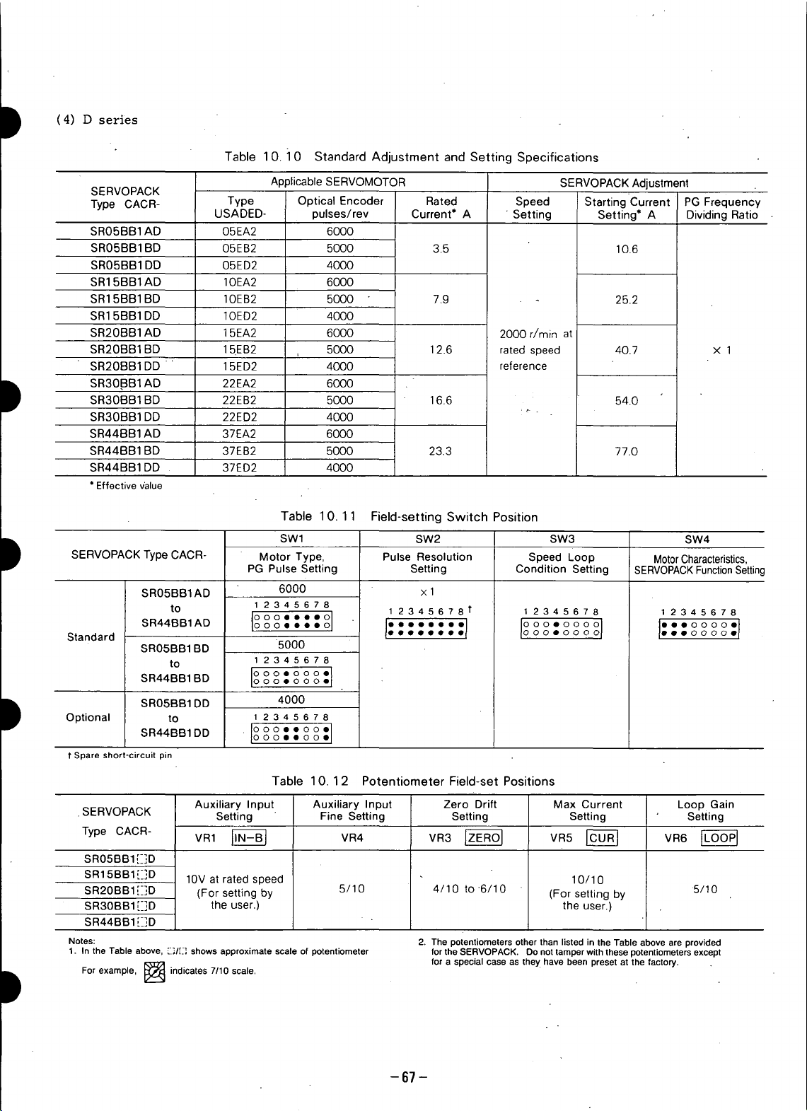
(4) D series
Table 10.10 Standard Adjustment and Setting Specifications
SERVOPACK
Applicable SERVOMOTOR SERVOPACK Adjustment
Type CACR- Type Optical Encoder Rated Speed Starting Current PG Frequency
USADED- pulses/rev Current* A " Setting Setting* A Dividing Ratio
SR05BB1AD 05EA2 6000
SR05BB1BD 05EB2 5000 3.5 10.6
SR05BB1DD 05ED2 4000
SR15BB1AD IOEA2 6000
SR15BB1BD lOEB2 5000 7.9 25.2
SR15BB1DD IOED2 4000
SR20BB1AD 15EA2 6000 2000 r/rain at
SR20BB1BD 15EB2 5000 12.6 ratedspeed 40.7 x 1
SR20BB1DD 15ED2 4000 reference
+ ,
SR30.BB1AD 22EA2 6000
SR30BB1BD 22EB2 5000 16.6 54.0
SR30BB1DD 22ED2 4000
SR44BB1AD 37EA2 6000
SR44BB1BD 37EB2 5000 23.3 77.0
SR44BB1DD 37ED2 4000
* Effective v'alue
Table 10.11 Field-setting Switch Position
SWl SW2 SW3 SW4
SERVOPACKType CACR- Motor Type, Pulse Resolution Speed Loop MotorCharacteristics,
PG Pulse Setting Setting Condition Setting SERVOPACK FunctionSettinc
SR05BB1AD 6000 x 1
to 1 2345678 1 2345678 t I 2345678 1 2345678
Standard . • • • • • oo• oo •• oo
SR44BB1AD ooeooo coo oo ooo oo eo oo
ooo....o J" " :1 io o o1 I" o° °'1
SR05BB1BD 5000
to 12345678
SR44BBIBD I°o°o°•ooe°°°:j
SROSBB1DD 4000
Optional to 1 2 3 4 5 6 7 8
SR44BBIDD oo°o•°°.•o ooo
1"Spare short-circuit pin
Table 10.12 Potentiometer Field-set Positions
Auxiliary Input Auxiliary Input Zero Drift Max Current Loop Gain
.SERVOPACK Setting Fine Setting Setting Setting Setting
Type CACR- VR1 _ VR4 VR3 _ VR5 _ VR6
SR05BB1E]D
SR15BB1[_]D 10V at rated speed 10/10
SR20BB1 [_]D (For setting by 5/10 4/10 to 6/10 (For setting by 5/10
SR3OBB1[_]D the user.) the user.)
SR44BB1 [_]D
Notes: 2. The potentiometers other than listed in the Table above are provided
1. In the Table above, [.I_/E] shows approximate scale of potentiometer for the SERVOPACK. Do not tamper with these potentiometers except
For example, I[:_a'._l indicates 7/10 scale.
for a special case as they have been preset at the factory.
-67 -
Page 69
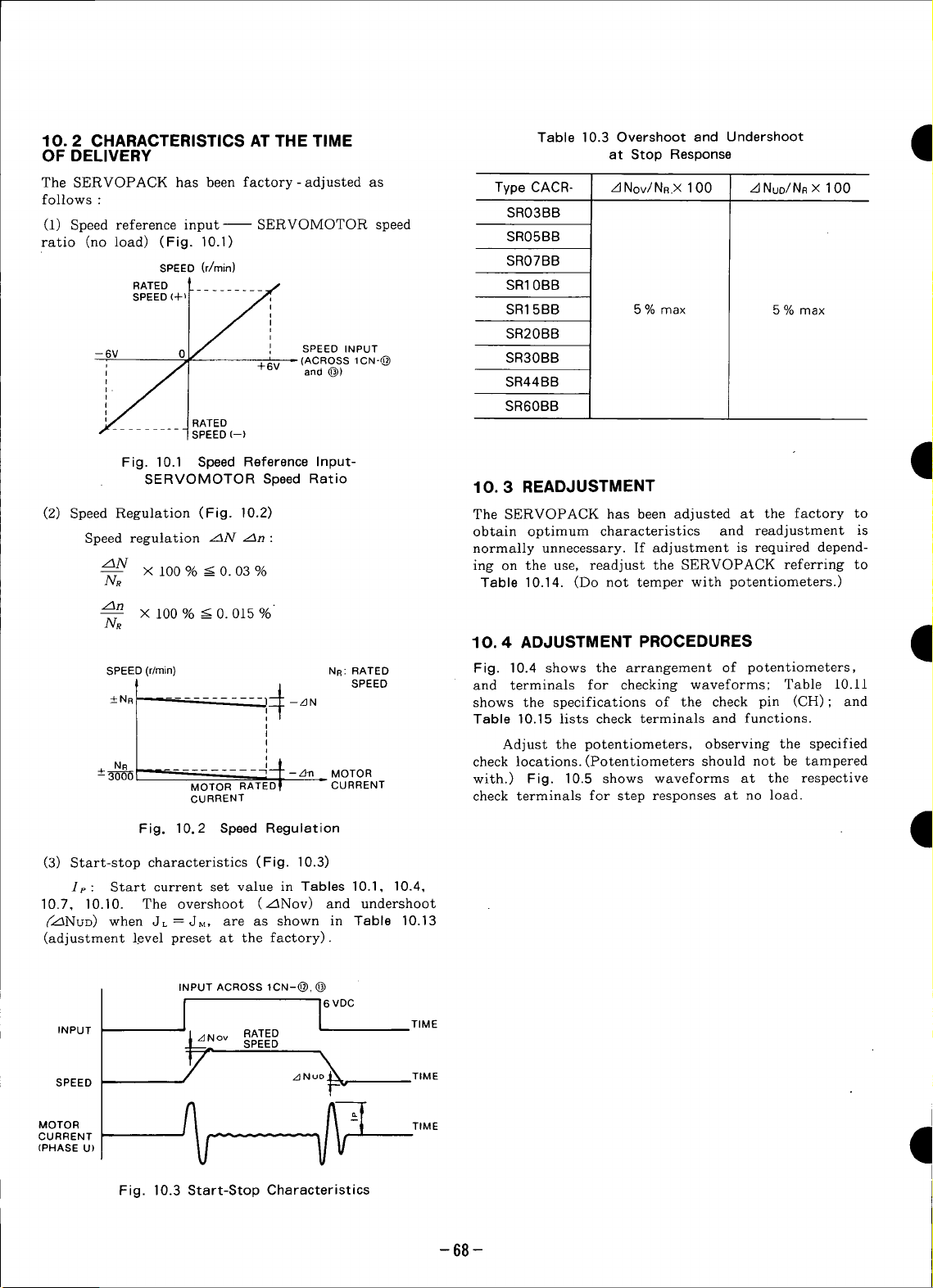
10.2 CHARACTERISTICS AT THE TIME Table 10.3 Overshoot and Undershoot
OF DELIVERY at Stop Response
The SERVOPACK has been factory-adjusted as Type CACR- zJNov/NR.X 100 z_Nuo/NRX 100
follows :
(1) Speed reference input SERVOMOTOR speed
ratio (no load) (Fig. 10.1) SR05BB
SPEED (r/min) SR07BB
RATED __......... _ SR10BB
s_o+p
--6V 0j_ , SPEED INPUT
; /I +6V and@)
r r SPEED (--)
(2) Speed Regulation (Fig. 10.2) The SERVOPACK has been adjusted at the factory to
Speed regulation zlN z3n: obtain optimum characteristics and readjustment is
z3N x 100 % < 0.03 % ing on the use, readjust the SERVOPACK referring to
NR Table 10.14. (Do not temper with potentiometers.)
zfln
NR
SPEED(r/rain) NR:RATED Fig. 10.4 shows the arrangement of potentiometers,
___ RATED
Fig. 10.1 Speed Reference Input- I
SERVOMOTOR Speed Ratio 10.3 READJUSTMENT
X 100%___0.015%
- (ACROSS1ca-@ SR30BB
SR03BB
SR15BB 5 % max 5% max
SR20BB
SR44BB
SR60BB
normally unnecessary. If adjustment is required depend-
10.4 ADJUSTMENT PROCEDURES I
Am
1
.all
"ql
,din
R N shows the specifications of the check pin (CH); and
__'-_- i SPEED and terminals for checking waveforms; Table 10.11
--+3_1 ,[--_. MOTOR with.) Fig. 10.5 shows waveforms at the respective
Fig.
(3) Start-stop characteristics (Fig. 10.3)
Ip: Start current set value in Tables 10.1, 10.4,
10.7, 10.10. The overshoot (z_Nov) and undershoot
(_z_NuD) when JL=JM, are as shown in Table 10.13
(adjustment level preset at the factory).
INPUT ov RATED
SPEED z_Nu_ TIME
CURRENT --_- -- -
(PHASE U)
MOTOR %_ _j,,_ __]'_'-_ TIME I
MOTOR RATED f CURRENT
CURRENT check terminals for step responses at no load.
10.2 SpeedRegulation I
INPUT ACROSS 1CN-@, @
TIME
SPEED
_/_ 6 VDC
Table 10.15 lists check terminals and functions.
Adjust the potentiometers, observing the specified
check locations. (Potentiometers should not be tampered
Fig. 10.3 Start-Stop Characteristics
-68-
Page 70

' il
D i_ v_o,8
Ff_q
RESET PUSHBUTTON
(7-SEGMENT)
_ TROUBLE LED INDICATION
VR2"t$
val0,'l$ O
VR12\I_"
1 VR13k_] _" '
VRT/,$
VR8
VR4_/--F--]
D 2CN ICN SERVOPACKType CACR-SRCA[-_REV.A
_ _l_ _ _ (a) PrintedOircuitBoardfor
D .I '
i_ E_] RESET PUSHBUTTON
VR9 O
VR10 _
VR.\ []
MR12 _
VR_3_(_)
(7-SEGMENT)
[_ TROUBLE LED INDICATION
D 8 TO117__
VR_ ] _
VR4
I I SERVOPACK Type CACR-SRCAr_-_REV.B
_1 2ON J_" '_1 1CN
Fig. 10.4 Arrangement of Potentiometers (VR),
Check Terminals and Switches (SW) -69-
VRe (b) Printed Circuit Board for
Page 71
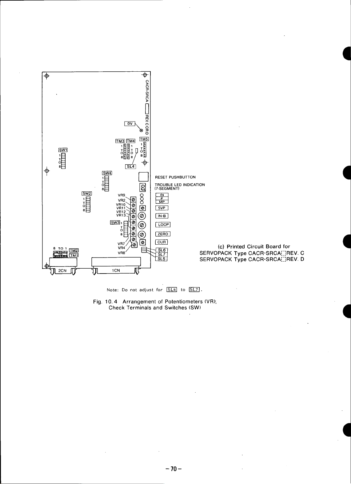
, _ °_ o_
il_ _ RESET PUSHBUTTON
VR9 O
vinoS. _ 0
i_ VR2"' O
VR,,\-- []
VR12"]
(7-SEGMENT)
-_ TROUBLE LED INDICATION
_ Vc-_N
8 To , I L_ (C) Printed Circuit Board for
I ] SERVOPACK Type CACR-SRCA[-_]REV. D
_ SERVOPACK Type CACR-SRCAE]REV. C
20.J_r _)_ ,ON _--
Note: Do not adjust for [_C4] to I_.
Fig. 10.4 Arrangement of Potentiometers (VR),
CheckTerminalsandSwitches(SW) _1
I
-70-
Page 72

Table 10.14 Potentiometer Adjustment
Potentiometer VR1-I,N-B I VR4 VR3 F_-ES] VR5 [-CO&]
Functions Auxiliary input adjustment Auxiliary input fine
To be adjusted only when To fine adjust the To adjust so that the Turning VR5 CCW de-
the rated reference voltage adjusted value of VR1. motor does not turn at creases the starting current.
How to than _-+6V. Turn VR1 only voltage 0 V. Turning full scale CCW at the
Adjust to get the rated speed and VR3 CW allows the motor factory.
(4-2 to +10V) is other the speed reference This has been adjusted to
do not operate other VRs. to be finely adjusted in
MOTORSPEED Adjustable in units of ,_ MOTORSPEED ROTATION)
+RATING
adjustment
Zero drift adjustment Starting current adjustment
forward rotation, and CCW
in reverse rotation.
(FORWARD
Characteristics
Adjustment O O O O
Potentiometer VR6 _ VR2 VR9" VR10
Functions adjustment f/V gain adjustment f/V zero adjustment f/V balance adjustment
How to To increase gain, turn Turning CW increases f/V circu{t offset _/V circuit +output
Adjust VR6 CW. feedback voltage, adjustment, voltage balance
Characteristics _ not run at the samespeed
Adjustment O x x x
Potentiometer VR7 VR8 -- --
Functions Torque reference Max current adjustment
How to Adjust at 3V. on types and motor output. -- _
Characteristics -- max current. -- _
--6V _ ]INPUT /P'/ js (+)
j_/a0 6V
.... CLOCKWISE _CW)
_--_ COUNTERCLOCKWISE .... CW
Speed loop gain
Turn VR6 CCW to Turning CW decreases If f/V balance adjustment
prevent hunting, motor speed, is not correct, motor does
adjustment -- --
Adjust to rated current Set max current depending
-- RATING p'#t/j/" ' INPUT --
(CCW) _-_ CCW
o,wlsetto L"12
(--) /;/ / REFERENCE
-/
(Turn VR5 CW to full scale.)
Turning CW increases
(REVERSE
ROTATION)
adjustment
in both directions under
the same absolute
reference voltage.
Adjustment x x -- --
Potentiometer VR11 VR12 VR13 VR21
Function Phase U current offset Phase V current offset Phase W current offset PG 5V voltage adjustment
How to Adjust phase U current amplifier phase V current amplifier phase W current amplifier It is set to 5.35V at the
Characteristics Incorrect adjustment increases torque ripple. Turning CW increases voltage.
Adjustmet x x x ._,
Adjustment Directions Mark A : Potentiometer shouid not be adjusted except in special cases.
Mark O : Potentiometer should be adjusted in accordance with specifi- Mark x : Do not adjust. •
adjustment, adjustment adjustment
With only control power With only control power With only control power PG power voltage
turned on, adjust until turned on, adjust until turned on, adjust until adjustment.
output voltage becomes output voltage becomes output voltage becomes factory.
minimum, minimum, minimum.
cations and application.
If wiring to PG is long. causing
voltage drop, increase voltage.
-71 -
Page 73
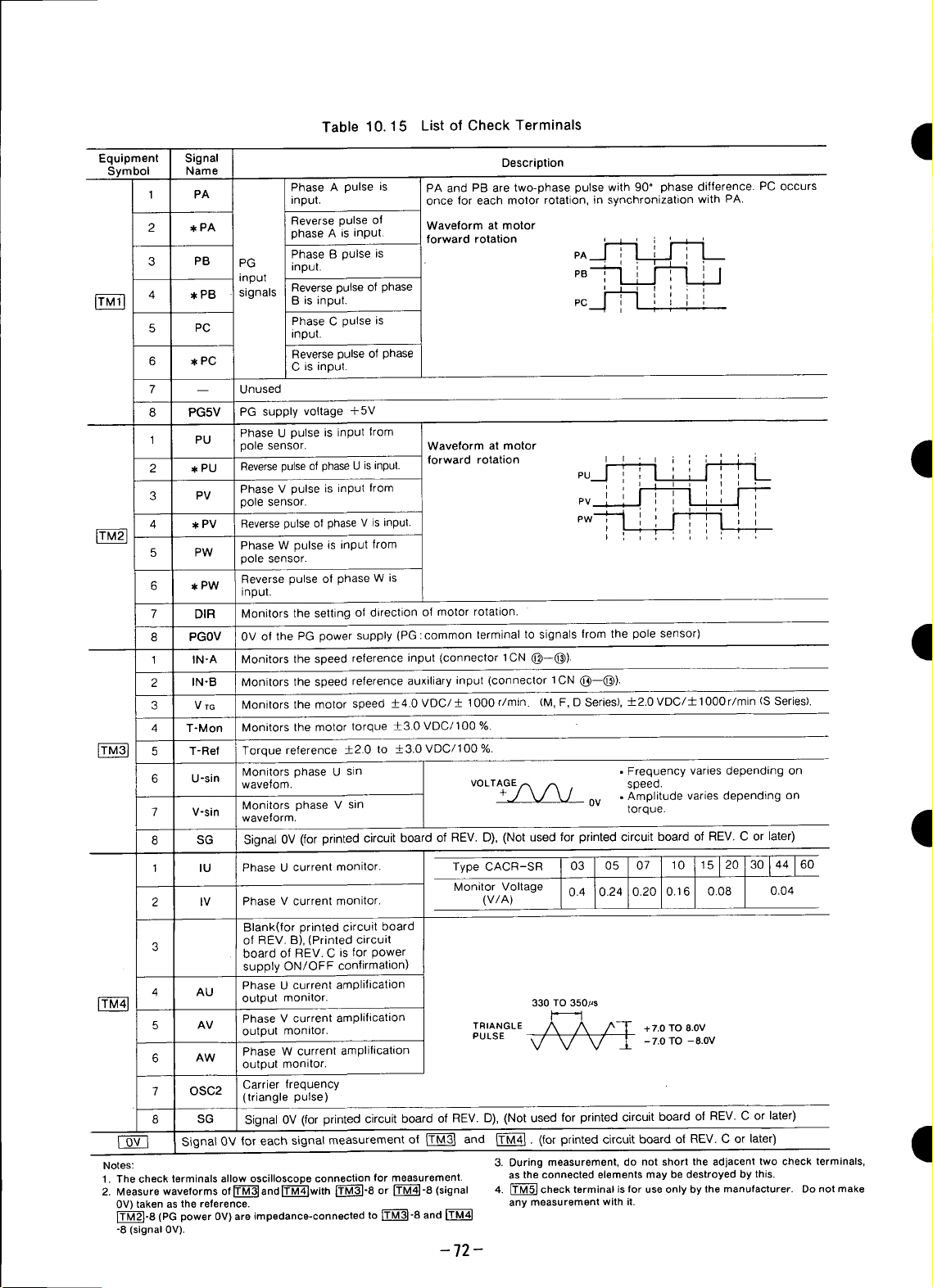
Table 10.15 List of Check Terminals
Equipment Signal Description
Symbol Name
1 PA input, once for each motor rotation, in synchronization with PA.
2 ,I,PA phase A is input, forward rotation
3 PB PG input. ' ' ' '
4 *PB signals Reversepulse of phase , , r ; ,
5 PC input.
6 W,PC C isinput.
7 -- Unused
8 PG5V PG supply voltage +5V
1 PU polesensor. Waveformatmotor
2 w,PU Reversepulseof phaseU isinput, forward rotation I m , _ , ,
3
4 w=PV Reversepulseof phase V is input. I I ! ! I
5 PW
6 w,PW
7 DIR Monitors the setting of direction of motor rotation.
input PB ,, ,
Phase U pulse is input from
PV Phase V pulse is input from , , _ , _ ,
Phase A pulse is PA and PB are two-phase pulse with 90" phase difference. PC occurs
Reverse pulse of Waveform at motor
Phase B pulse is pA__.] I [____'_
Bisinput. PC i _, '
Phase C pulse is
Reverse pulse of phase
_olesensor. PV I '* ' _ ' I ',
Phase W pulse is input from
3ole sensor.
Reverse pulse of phase W is
input.
' LLr--1 I
_ ' ,
PU i I 1 Ii .I--,
, _ i i i ,
i
i
,,
PW
,,
I ' i
' , ; , , ,, ,
,,
I
',
8 PGOV 0V of the PG power supply (PG :common terminal to signals from the pole sensor)
1 IN-A Monitors the speed reference input (connector 1CN (_)--(_).
2 IN-B Monitors the speed reference auxiliary input (connector 1CN (_)--(_)).
3 V TG Monitors the motor speed _+4.0 VDC/_+ 1000 r/rain. (M, F, D Series),-+-2.0VDC/± 1000 r/min (S Series).
4 T-Mon Monitors the motor torque _+3.0VDC/100 %.
r_ 5 T-Ref Torque reference +__2.0to _+3.0VDC/100 %.
6 U-sin wavefom. VOLTAGErx _ , speed.
7 V-sin waveform. •
8 SG Signal 0V (for printed circuit board of REV. D), (Not used for printed circuit board of REV. C or later)
1
2 IV Phase V current monitor. (V/A)
3 board of REV. C is for power
4 AU
5 AM output monitor. TRIANGLE VV -L' /A_ /Av/_7- +7.OTO8.0V
6 AW Phase W current amplification
7 OSC2 Carrier frequency
8 SG Signal 0V (for printed circuit board of REV. D), (Not used for printed circuit board of REV. C or later)
I OV I Signal 0V for each signal measurement of ITM31 and ITM41. (for printed circuit board of REV. C or later) i
Notes: 3. During measurement, do not short the adjacent two check terminals,
1. Thecheck terminals allow oscilloscope connection for measurement, as theconnected elementsmay be destroyed by this.
2. Measurewaveforms ofr=_--_andr_'M"_with[_]-8 or _-8 (signal 4. _ check terminal isfor useonly by themanufacturer. Donot make
0V)taken asthe reference, any measurementwith it.
rT--_]-8(PG power 0V)are impedance-connectedto rt--M-_-8and
-8 (signal 0V).
Monitors phase U sin • Frequency varies depending on
Monitorsphase V sin 0v torque.
PhaseUcurrent
IU
Blank(for printed circuit board
of REV. B), (Printed circuit
supply ON/OFF confirmation)
Phase U current amplification
output monitor. 330TO350,us
Phase V current amplification I_ LI
output monitor.
(triangle pulse)
monitor. Type CACR-SR 03 05 07 10 15 120 30 144 160
Monitor Voltage 0.4 0.24 0.20 0.16 0.08 0.04
PULSE -7.0TO -8.0V
• Amplitude varies depending on
-72-
,q
1
1
Page 74
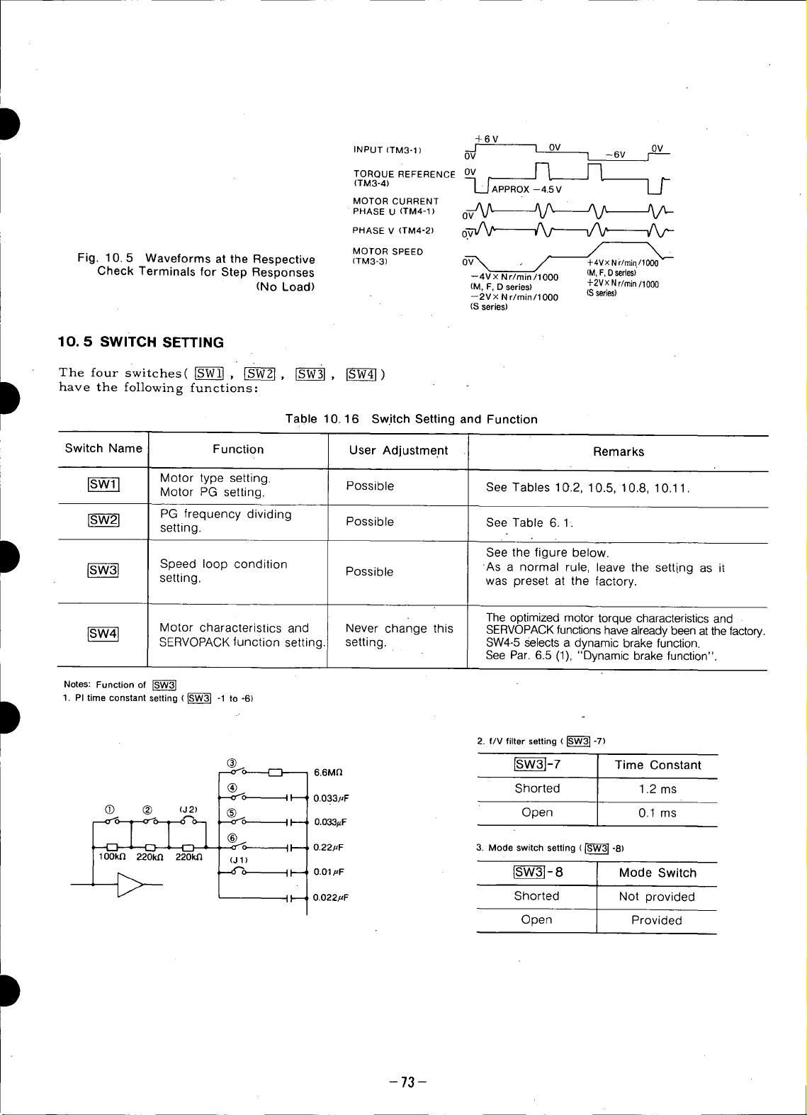
I +6V
INPUT(TM3-t) ---J I OV 0V
TORQUEREFERENCE0v _ _--
(TM3-4) U APPROX --4.5 V L.J
MOTOR CURRENT
OV 1 -6V ]
O"ASEV,TM'-2)0V--'/V Jr-
Fig. 10.5 Waveforms at the Respective (TM3-3) _ / +4VxNr/rnin./lO00
Check Terminals for Step Responses --4VxNr/min/lO00 (M,F.Dseries)
(No Load) (M, F, D series) +2VXNr/rnin/1000
10.5 SWITCH SETTING
The four switches( [SW-_ , [-_-W--_, [-S--_,
have the following functions:
Table 10.16 Switch Setting and Function
Switch Name Function User Adjustme.nt Remarks
Motor type setting.
Motor PG setting. Possible See Tables 10.2, 10.5, 10.8, 10.1 1.
PG frequency dividing
setting. Possible SeeTable 6.1.
MOTORSPEEO /
-- 2V x Nr/min /1000 (Sseries)
(S series)
.
t Seethefigurebelow.
S__ setting.Speedloop condition Possible ASwasapresetnOrmalatrUle,thefactory.leavethe setting as it
Notes: Function of
1. PI time constant setting ( _ -1 to -6)
(_) (_) (J2) _-_
_k _[ %c,- _1--.- 0.22,uF 3. Mode switch setting (_]-8)
The optimized motor torque characteristics and
Motor characteristics and Never change this SERVOPACK functions have already been at the factory.
SERVQPACK function setting, setting. SW4-5 Selects a dynamic brake function.
See Par. 6.5 (1), "Dynamic brake function".
2. f/V filter setting ( _ -7)
_-_o-----[_ 6.6M_ _SW-3_- 7 Time Constant
Shorted 1.2 ms
Open 0.1 ms
/_ (J1)
It--- 0.033,uF
I I'-----
O.O_#F
II-- 0.01_,F _S--W-_-8 Mode Switch
II-- 0.022,uF Shorted Not provided
Open Provided
-73--
Page 75

11. INSPECTIONANDMAINTENANCE
11.1 AC SERVOMOTOR
The AC SERVOMOTOR has no wearimg parts (e. g. Do not disassemble the motor, if disassembly is
brushes), so simple daily inspection is sufficient. Table necessary, contact your YASKAWA representative.
11.1 shows the inspection schedule for the motor.
Table 11.1 Inspection Schedule for Motors
Inspection Item Frequency Inspection Operation
Vibration Feel manually. If abnormal vibration or noise is found, con-
Noise Aurally tact your YASKAWA representative.
Exterior and Cleaning As required Clean with dry cloth or compressed air.
Insulation Make sure that it is more than 10MQ by measuring with a 500V
Resistance Annually megger after disconnecting the motor from the controller:
Shaft Seal Every 5,000 hours If grease is used for lubrication, replace every 3000 hours. I
Overhaul from the driven machine.
• Parts Replacement Schedule
Daily
Every 20, 000 hours
or 5 years Contact your YASKAWA representative.
If worn or damaged, replace after disconnecting the motor
m
dl
The following parts should be replaced periodically
since they may become worn mechanically or deterio-
ratedwith age.
Table 11.2 Parts Replacement Schedule
Part Name Interval Remarks
Every Disassemble the motor to replace "
Bearing 20,000 hours with new one.
Shaft Seal Every Replace with new one.
5,000hours _nl
.din
1
I
- 74-
Page 76

D 11.2 SERVOPACK
SERVOPACK does not require any daily maintenance.
However, it is advisable to perform the following
maintenance at least once a year.
Table 11.3 Inspection Schedule for SERVOPACK
Inspection Item Frequency Operation Corrective Action
Cleaning of Visually check for dust or oil on parts. Clean with dry cloth or compressed air.
SERVOPACK and board
Check for loose screws of teminals and
Loose screws connectors of 1 CN and 2CN of Retighten.
Every SERVOPACK.
Deterioration of 1 year Visually check for discoloration,
SERVOPACK and/or breakage or disconnection resulting
parts on board from heat, bumping, etc. Contact your YASKAWA representative
D Cooling fan Check if the fan rotates normally.
• Parts Replacement Schedule
The following parts should be replaced periodically
since they may become worn mechanically or
deteriorared with age.
Table 11.4 Parts Replacement Schedule
Cooling fan 2 to 3 years Replace with new one.
Smoothing capacitor 7 to 8 years Replace with new one. (Decided after inspection)
PartName Interval Remarks
Circuit protector or relays -- Upon inspection, decided whether they should be replaced.
Fuse 10years Replacewith new one.
Aluminum electrolytic capacitor on PC board 5 years Replace with new board. Decided after inspection)
Note: Optimum operating environment is as follows:
Ambient temperature : 30 °C on average
Load factor : 80 _ or less
Operating rate : 20 hours or less per day
-75-
Page 77

12. TROUBLESHOOTING GUIDE
12.1 AC SERVOMOTOR
Remedies in _ should be practiced
after turning OFF the power.
Table 12.1 Troubleshooting Guide for AC SERVOMOTOR
Trouble Cause Whattodo
WARNING
Voltage below rated
Loose connection Tighten connection.
Motor does not
start.
Unstable operation _ Wrong wiring V, and W, and PG. _.... _ _ _ _
Motor overheats. Motor surface is dirty Clean motor surface.
Wrong wiring Correct wiring.
Overload load or use a larger motor.
Motor defective
Excessive ambient Reduce ambient temperature below 40°C.
temperature.
Overload Reduce load or use a larger motor.
Motor loosely mounted Tighten foundation bolts.
Motor misaligned Realign.
Measure voltage across motor terminals U, V, and W
with a tester and correct to rated value.
Measure voltage across motor terminals U, V, and W
with a tester. When correct, replace motor.
Inspect and correct wprung across motor terminals U, _]
Unusual noise Coupling out of balance Balance coupling.
Noisy bearing
Vibration of driven machine Contact the machine manufacturer.
Check alignment, noise of bearing, lubrication and contact
your YASKAWA representative.
-76-
Page 78

D 12.2 SERVOPACK
12.2.1 LED Indication (7-segment) for Troubleshooting
LED Detection Lighting Condition Probable Cause Corrective Action
[_] Over- Goes ON when power is supplied to the • Defective motor grounding • Replace the motor.
-_ Goes ON when power is supplied to the * Defective main circuit thyristor- • Replace the SERVOPACK.
Table 12.2 LED Indication for Troubleshooting
Goes ON when power issupplied to the • Defective control circuit board • Replace the SERVOPACK.
control circuit. (1 PWB).
Goes ON when power issupplied to the •° Defective current feedback circuit. • Replace the SERVOPACK.
main circuit and servo power is turned • Defective main circuit transistor • Correct grounding.
ON. module.
• MCCB does not trip. • Motor grounding
current main circuit and servo power is turned • Defective main circuit transistor • Replace the SERVOPACK.
Circuit
protector
tripped • MCCBtrips. '.
ON. module.
• MCCB does not trip.
Goes ON when power is supplied to the • Defective main circuit transistor • Replace the SERVOPACK.
main circuit, module.
Goes ON when the motor accelerates ,'Incomplete (1 PWB) VR8 • Replace the SERVOPACK.
or decelerates. - adjustment.
Goes ON when power is supplied to the • Defective control circuit board • Replace the SERVOPACK.
control circuit. (1 PWB).
main circuit, diode module.
Goes ON during operation. (Do not turn ON again.)
• Defective main circuit of SERVOPACK
D . .. Goes ON when power is supplied to the • Defective control circuit board. • Replace the SERVOPACK.
D "
I _] and [] goes ON again. • Temperature around the • Decrease the temperature below
D " overheat The motor rotates, but the torque is un- • Motor circuit error connection, • Correct the connection.
Regener- control circuit. (1 PWB).
_] ative Goes ON approximate 0.5 to 1 second • Defective regenerative transistor. • Replace the SERVOPACK.
trouble circuit. • Regenerative resistor disconnection. • Check and replace the regenerative
Over- or decelerates, with the value converted to the
r__ motorShaft.
voltage
Over- runs fast and [] goes ON. . Optical encoder connectior_ error. • Check pulses in phases A, B, C, U,
-_ VandWon2CN,andcorrectwiring.
speed
[_ Voltage Goes ON when power is supplied to the • Defective main circuit thyristor- • Replace the SERVOPACK.
drop main circuit. " diode module.
Overload • When power to the control circuit is more of the rated load. (may be overload).
Heat When reset later, the operation SERVOPACK exceeds 551C. 55°C (The heat sink may be
[_] sink
after power is supplied to the main
• No regenerative resistor resistor. (Replace the SERVOPACK.
connection (SR60BB) -
Goes ON when the motor accelerates • Load inertia JL (GD 2) is too large. • Check the inertia of the machine
• Defective regenerative circuit. • Replace the SERVOPACK.
When the reference is input, the motor • Motor connection error. ° Correct the motor connection.
• The reference input voltage is too • Decrease the reference input
large, voltage.
Goes ON when power is supplied to the • Defective control circuit board • Replace the SERVOPACK.
control circuit. (1 PWB).
Goes ON during operation. • Operation with 105% to 130% or • Check and correct the load
turned OFF and then ON again, the
operation starts.
Goes ON during operation. • Fan has stopped. • Check the fan.
• When power to the control circuit is (SR20, 30, 44, 60)
turned OFF and then ON again,
starts, overheated.)
available. When power to the control such as U--*V, V_W, W-.U or
circuit is turned OFF and then ON again, single-phase connection.
the operation starts, but the torque is still
unavailable. .
-77-
Page 79

12.2.1 LED Indication (7-segment) for Troubleshooting (Cont'd)
Table "_2.2 LED Indication for Troubleshooting (Cont'd)
LED Detection Lighting Condition Probable Cause Corrective Action
A/D error Goes ON when power is supplied to the • Defective control circuit board • Replace the SERVOPACK.
_1 CPU error Goes ON during operation. • Faulty internal elements. • Resume after reset operation.
Open control circuit. (1 PWB).
phase Goes ON when power is supplied to the • Poor connection to 3-phase • Check and correct the
-_ Overrun The motor starts momentarily, then • Motor connection error. • Correct the motor connection. ,all
prevention [] goes ON. • Optical encoder connection • Check and correct pulses in
12.2.2 Examples of Troubleshooting for Defective Wiring or Parts
MCCB trips immediately after Power • Main circuit wiring (such as the ground • Correct the wiring.
ON and Servo ON. of motor)
The reference is input, but the motor • Voltage across ®, ®, and O. • Check the AC power supply circuit.
does not run. • LED [] and _ ON
control circuit. (1PWB).
• Defective internal elements. • Replace the SERVOPACK.
Goes ON when power is supplied to the • Defective control circuit board • Replace the SERVOPACK.
main circuit, power supply, connection.
Goes ON when power is supplied to the • Defective control circuit board • Replace the SERVOPACK.
control circuit. (1 PWB).
error, phases A, B, C, U, V and W
Table 12.3 Example of Troubleshooting for Defective Wiring or Parts
Trouble CheckItems Whatto do
• Trouble LED OFF o If LEDs are ON, check the cause.
• Speed reference voltage • Adjust the speed setting
• LED _ ON potentiometer (supplied by
• P-CON, N-OT, P-OT, S-ON signal
with 2CN.
the user).
I
12.2.3 Examples of Troubleshooting for Incomplete Adjustment
Table 12.4 Examples of Troubleshooting for Incomplete Adjustment
Trouble Cause Whattodo
Motor rotates even if the speed refer- Incomplete ZERO potentiometer adjust- Adjust VR3 _ correctly.
ence voltage is 0 V. ment.
Motor vibrates or vibration frequency is Speed loop gain is too high Turn VR6 _ CCW to decrease the
too high, approx 200 to 300 Hz. • Excessively long lead of SERVOPACK speed loop gain.
(When vibration frequency equals input circuit. * Decrease length of lead.
commercial frequency.) • Noise interference due to bundling of • Separate input circuit line from power
signal line and power line. line or connect input circuit to low
Motor speed overshoot is too large at • Speed loop gain is too high • Turn _ CCW to decrease the
starting or stopping, speed loop gain.
impedance less than several 100 ohms.
-78-
Page 80
{ NOTES1
-79-
Page 81

AC SERVO DRIVE MoFoS-D SERIES
BULLETIN
TOKYO OFFICE New Pier Takesiba Soulh Tower, 1-16-1, Kaigan, Minatoku, Tokyo 105 Japan
Phone 81-3-5402-4511 Fax 81-3-5402-4580
YASKAWA ELECTRIC AMERICA, INC.
Chicago-Corporate Headquarters 2942 MacArthur Blvd. Northbrook, IL 60062-2028, U.SA.
Phone 1-847-291-2340 Fax 1-847-498-2430
Chicago-Technical Center 3160 MacArthur Blvd. Northbrook, IL 60062 1917, U.S.A
Phone 1-847-291-0411 Fax 1-847-291-1018
MOTOMAN INC.
805 Liberty Lane West Carrollton, OH 45449, U.S.A.
Phone 1-513-847-6200 Fax 1-513-847-6277
YASKAWA EL_:TRICO DO BRASlL COMI_RClO LTDA.
Avenida Brigadeiro Faria Lima 1664-5"CJ 504/511, S&o Paulo, Brazil
Phone 55-11-815-77.23 Fax 55-11-870-3849
YASKAWA ELECTRIC EUROPE GmbH
Am Kronberger Hang 2, 65824 Schwalbach, Germany
Phone 49-6196-569-300 Fax 49-6196-888-301
Motoman Robotics AB
Box 504 $38525 Tots&s, Sweden
Phone 46-486-10575 Fax 46-486-41410
Motoman Robotec GmbH
Kammerfeldstra,Ge l, 85391 Allershausen, Germany
Phone 49-8166-900 Fax 49-8166-903_)
YASKAWA ELECTRIC UK LTD.
3 Drum Mains Park Orchardton Woods Cumbernauld, Scotland, G68 9LD U.K.
Phone 44 1236-735000 Fax 44-1236-458182
YASKAWA ELECTRIC KOREA CORPORATION
Paik Nam Bldg. 901 188-3, 1-Ga Euljiro, Joong-Gu Seoul, Korea
Phone 82-2-776-7844 Fax 82-2-753-2639
YASKAWA ELECTRIC (SINGAPORE) PTE. LTD.
151Loron 9 Chuan, #04-01, New Tech Park Singapore 556741, Singapore
Phone 65-282-3003 Fax 65-289-3003
YATEC ENGINEERING CORPORATION
Shen Hsiang Tang Sung Chiang Building 10F 146 Sung Chiang Road, Taipei, Taiwan
Phone 886 2-563-0010 Fax 886-2-567-4677
BEIJING OFFICE Room No. 301 Office Building of Beijing International Club, 21 Jianguomenwai Avenue, Beijing 100020, China
Phone 86-10-532-1850 Fax 86-10-532-1851
SHANGHAI OFFICE Room No. 8B Wan Zhong Building 1303 Yan An Road (West), Shanghai 200050, China
Phone 86 21-6212-1015 Fax 86-21-6212-1326
YASKAWA JASON (HK) COMPANY LIMITED
Rm.2916, Hong Kong Plaza, 186-191Connaught Road West, Hong Kong
Phone 852-2858-3220 Fax 852-2547-5773
TAIPEI OFFICE Shen Hsiang Tang Sung Chiang Building 10F 146 Sung Chiang Road, Taipei, Taiwan
Phone 886 2-563-0010 Fax 886-2-567-4677
YASKAWA ELECTRIC CORPORATION
YASKAWA
TSE-S800-2.1J
Duetoongo#_gproductmodification/improvement,datasubjectto changewithoutnotice. 586-23,386-3
© Printed in Japan June 1996 85-1 2WA <_
 Loading...