

Page 1
Step
1
Option Card Information
Receiving
Please perform the following tasks upon receipt of the
option:
· Inspect the option for damage. Contact the shipper
immediately if the option appears damaged upon
receipt.
· Verify receipt of the correct model by checking the
model number printed on the name plate of the
option package.
· Contact your supplier if you have received the
wrong model or the option does not function
properly.
Tools required for installation
· A Phillips screwdriver (M3 metric/#1, #2 U.S. standard
size) is required to install the option and remove drive
front covers. Screw sizes vary by drive capacity.
Select a screwdriver appropriate for the drive
capacity.
· Diagonal cutting pliers. (required for some drive
models)
· A small file or medium grit sandpaper. (required for
some drive models)
· A straight-edge screwdriver (blade depth: 0.4 mm,
width: 2.5 mm) is required to wire the option terminal
block.
Applicable Models
The option can be used with the following drive models:
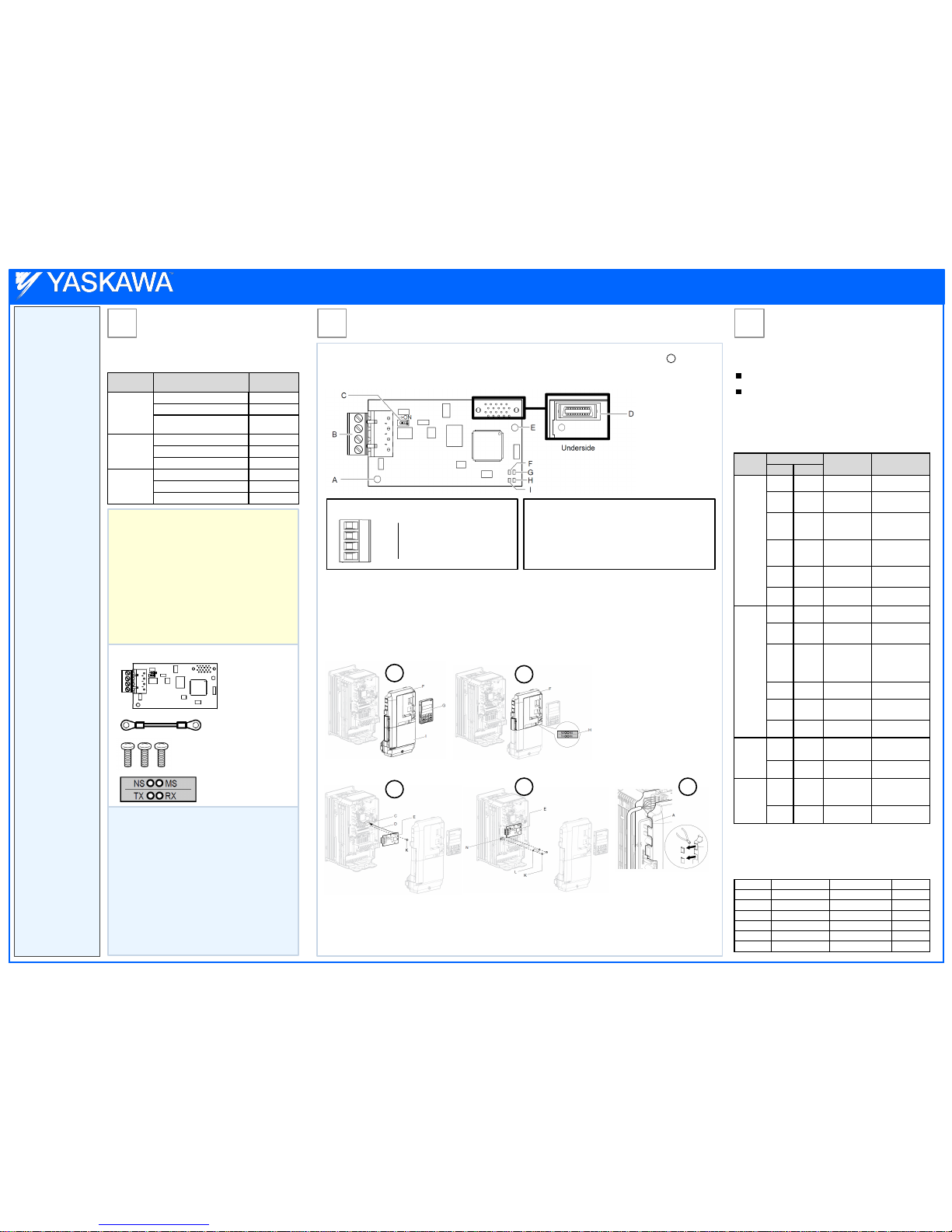
Option Package Contents
Option PCB – 1x
PN: UTC00043o
Ground Wire – 1x
Screws (M3) – 3x
LED Label – 1x
Option LED Display and
Power-Up Diagnostics
Step3Step
2
Installing the SI-B3 Option Card
The following
procedure is a
supplement to
other
documentation
supplied with the
SI-B3 option card.
This document
will cover option
card information,
installation,
diagnostics,
addressing,
related drive
parameters,
accessing drive
parameters and
error codes.
Drives can be
monitored and
controlled by a
controller on a
Building
Automation and
Control network
(BACnet) using RS485 technology
and MS/TP
(Master-Slave/
Token-Passing)
protocol. The
drives conform to
the BACnet
application
specific controller
(B-ASC) device
profile. Up to 127
drives can
communicate on a
single BACnet MS/
TP network.
Please read this
cheat sheet and
other
documentation
provided with
the SI-B3 option
card thoroughly
before
attempting any
installation.
Page 1 of 2
In this step the SI-B3 option card is installed. WITH POWER OFF install the SI-B3 card as shown below. Make sure to follow good
wiring practices and all applicable codes. Ensure that the option card is grounded properly as shown in item below.
This option card can be inserted into the CN5-A connector located on the drive’s control board.
Option Card Installation
- Ground terminal and installation hole <1>
- Terminal block TB1
- Terminating resistor switch S1
- Connector (CN5)
- Installation hole
- LED (NS)<2>
- LED (MS)<2>
- LED (RX)<2>
- LED (TX)<2>
A
B
C
D
E
F
G
H
I
SI-B3 Option Card
<1> Connect the ground wire provided in the
option shipping package during installation.
<2> Refer to Option LED section Step 3 for
details on the LEDs.
1
2
3
4
IG5
+
SHLD
Terminal Block TB1
Remove the Front Covers and Digital Operator Apply the LED Label
Insert the Option
Connect the Ground Wire
A
B
C
D
E
F
G
H
I
J
K
L
M
N
Connector CN5-C
Connector CN5-B
Connector CN5-A
Insertion point for CN5 Connector
SI-B3 option
Drive front cover
Digital operator
LED label
Drive terminal cover
Removable tabs for wire routing
Included screws
Ground wire
Terminal block TB1
Drive grounding terminal (FE)
Prior to installing the option, wire the drive, make necessary connections to the drive terminals, and verify that the drive functions normally without the option
installed. Refer to the Quick Start Guide packaged with the drive for information on wiring and connecting the drive. Shut off power to the drive, wait the
appropriate amount of time for voltage to dissipate, then remove the digital operator (G) and front covers (F, I). Front cover removal varies by model.
DANGER! Electrical Shock Hazard. Do not connect or disconnect wiring while the power is on. Failure to comply will result in death or serious injury. Before
installing the option, disconnect all power to the drive. The internal capacitor remains charged even after the power supply is turned off. The charge indicator
LED will extinguish when the DC bus voltage is below 50 Vdc. To prevent electric shock, wait at least five minutes after all indicators are off and measure the
DC bus voltage level to confirm safe level.
NOTICE: Damage to Equipment. Observe proper electrostatic discharge procedures (ESD) when handling the option, drive, and circuit boards. Failure to
comply may result in ESD damage to circuitry.
Wire routing
1
2
3
4 5
Depending on the drive model, some drives may require routing the wiring through the side of the front cover to the outside to provide adequate space for the
wiring. In these cases, using diagonal cutting pliers, cut out the perforated openings on the left side of the drive front cover. Sharp edges along the cut out
should be smoothed down with a file or sand paper to prevent any damage to the wires. Route the communication wiring inside the enclosure for drives that do
not require routing through the front cover.
Wiring the Option
Isolated supply ground reference
RX/TX (+) signal
RX/TX (-) signal
Shield Ground
4
Note: ‘A’ indicates wire routing.
SI-B3 BACnet Option Cheat Sheet
Drive Series Drive Model
Software
Version
A1000
CIMR-A*2A**** 1017 or later
CIMR-A*4A0002* to 4A0675* 1017 or later
CIMR-A*5A****
1017 or later
5045 or later
CIMR-P*2A**** 8500 or later
P1000 CIMR-P*4A0002* to 4A0675* 8500 or later
CIMR-P*5A**** 8500 or later
iQpump1000
CIMR-PW2A**** 8550 or later
CIMR-PW4A0002* to 4A0675* 8550 or later
CIMR-PW5A*** 8550 or later
Option LED Display
The BACnet option has four LEDs.
Two bi-color Status LEDs:
Module status (MS) and Network status (NS) (red/green)
Two BACnet LEDs:
Transmit (TX) and Receive (RX) (green)
The operational states of the option LEDs after completion of
the BACnet power-up diagnostic LED sequence are
described in the table below. Wait at least 2 seconds for the
power-up diagnostic process to complete before verifying
LED states.
An LED test is performed each time the drive is powered
up. The initial boot sequence may take several seconds.
After the LEDs have completed the diagnostic LED
sequence, the option is successfully initialized. The LEDs
then assume operational conditions as shown in the table
below.
Power-Up Diagnostics
Name
Display
Operating
Status
Remarks
Color Status
MS
– OFF
Power supply
OFF
Power is not being supplied to the drive.
Green ON Normal operation
The option is operating
normally and initialization is complete.
Green Flashing
Standby/
Initializing
The option is in process
of configuring or waiting
for configuration information.
Red Flashing
Minor fault
The option has detected
a recoverable minor
fault such as incomplete
configuration.
Red ON Major fault
The option has detected
an unrecoverable major
fault.
Green/
Red
Flashing Option self-test
The option is in self-test
mode.
– OFF
Power supply
OFF
–
NS
Green ON Connected
The device is currently
communicating on the
network.
Green Flashing
Not connected
The device currently is
not communicating, but
is correctly configured.
The state is “waiting” for
communication to resume.
Red Flashing Minor fault
A minor recoverable
fault has occurred.
Red ON Major fault
A non-recoverable major network fault has
occurred.
Green/
Red
Flashing
Network test
Power-up sequence and
testing.
TX
– OFF
No data being
sent to the network
This node is not sending
any data.
Green Flashing
Data being sent
to the network
This node is sending
network data.
RX
– OFF
No data seen on
the network
The option is not physically connected to the
network or there is no
network activity.
Green Flashing
Data is seen on
the network
The option is connected
to a network.
Sequence Module Status (MS) Network Status (NS) Time (ms)
1 Green OFF 250
2 Red OFF 250
3 Green OFF –
4 Green Green 250
5 Green Red 250
6 Green OFF –
Yaskawa America, Inc., 2121 Norman Drive South, Waukegan, IL 60085, (800) YASKAWA (927-5292) Fax (847) 887-7310, [email protected], www.yaskawa.com, Document Number: TM.BACnet.01 11/28/2012 © Yaskawa America,
Page 2
Page 2 of 2
SI-B3 BACnet Option Cheat
BACnet Objects and Accessing Drive Parameters
Step
5
BACnet Node Addressing and
Related Drive Parameters
Step
4
BACnet Node Addressing
The BACnet node address is configurable by parameter F645 in the drive. This defines the physical address of the drive
on the MS/TP network. In addition, both the Device Object
Instance Identifier (parameters F6-48 and F6-49) and the
Device Object Name are configurable. These allow the drive
to have a virtual address and simplify the controller
configuration.
After setting the addressing, a controller can initiate
communication to the drive. The drive will perform the
specified function and then send a response back to the
controller. The drive will usually respond immediately, but
may delay its response until it gets the token for commands
that may take extra local processing time.
Related Drive Parameters
The following parameters are used to set up the drive for
operation with the option. Parameter setting instructions can
be found in the drive Quick Start Guide or Technical Manual.
Confirm proper setting of the all parameters in the table
below, before starting network communications. After
changing parameter settings, cycle power to the drive for the
new settings to take effect.
<1> To start and stop the drive with the option master device using
serial communications, set b1-02 to 3. To control the drive frequency
reference via the master device, set b1-01 to 3.
<2> These parameters set the Instance Identifier of the BACnet
Device Object, where the F6-48 value is the least significant word
and the F6-49 value is the most significant word.
Example 1: Set the Device Object Instance Identifier of "1234". 1234
decimal is equal to 4D2H (hexadecimal). Set F6-48 to 4D2H and
F6-49 to 0.
Example 2: Set Device Object Instance Identifier to "1234567".
1234567 decimal is equal to 12D687H. Set
F6-48 to D687H and set F6-49 to 12H.
No. Name Description Values
b1-01
<1>
Frequency
Reference
Selection
0: Operator
1: Terminals - A1 or A2
2: MEMOBUS/Modbus
3: Option PCB
4: Pulse Input
Default: 1
Range: 0 to 4
(Set to 3 for BACnet)
b1-02
Run
Command
Selection
0: Digital Operator
1: Digital input terminals
2: MEMOBUS/Modbus
3: Option PCB
Default: 1
Range: 0 to 3
(Set to 3 for BACnet)
F6-45
Drive Node
Address
Sets the BACnet MS/TP
MAC address
(physical node address).
Default: 1
Range: 0 to 127
F6-46
Comm.
Speed
Selection
Sets the comm. speed.
0: 1200 bps
1: 2400 bps
2: 4800 bps
3: 9600 bps
4: 19200 bps
5: 38400 bps
6: 57600 bps
7: 76800 bps
8: 115200 bps
Default: 3
Range: 0 to 8
F6-47
Drive
Transmit
Wait
Time
Sets the time the drive
waits after receiving data
from a master before
transmitting response
data.
Default: 5 ms
Range: 5 to 65
F6-48
<2>
BACnet
Device
Object
Identifier 0
Set the Instance Identifier
of the BACnet Device
Object, where the F6-48
value is the least significant word.
Default: 1
Range: 0 to FFFFH
F6-49
<2>
BACnet
Device
Object
Identifier 1
Set the Instance Identifier
of the BACnet Device
Object, where the F6-49
value is the most significant word.
Default: 0
Range: 0 to 3FH
`
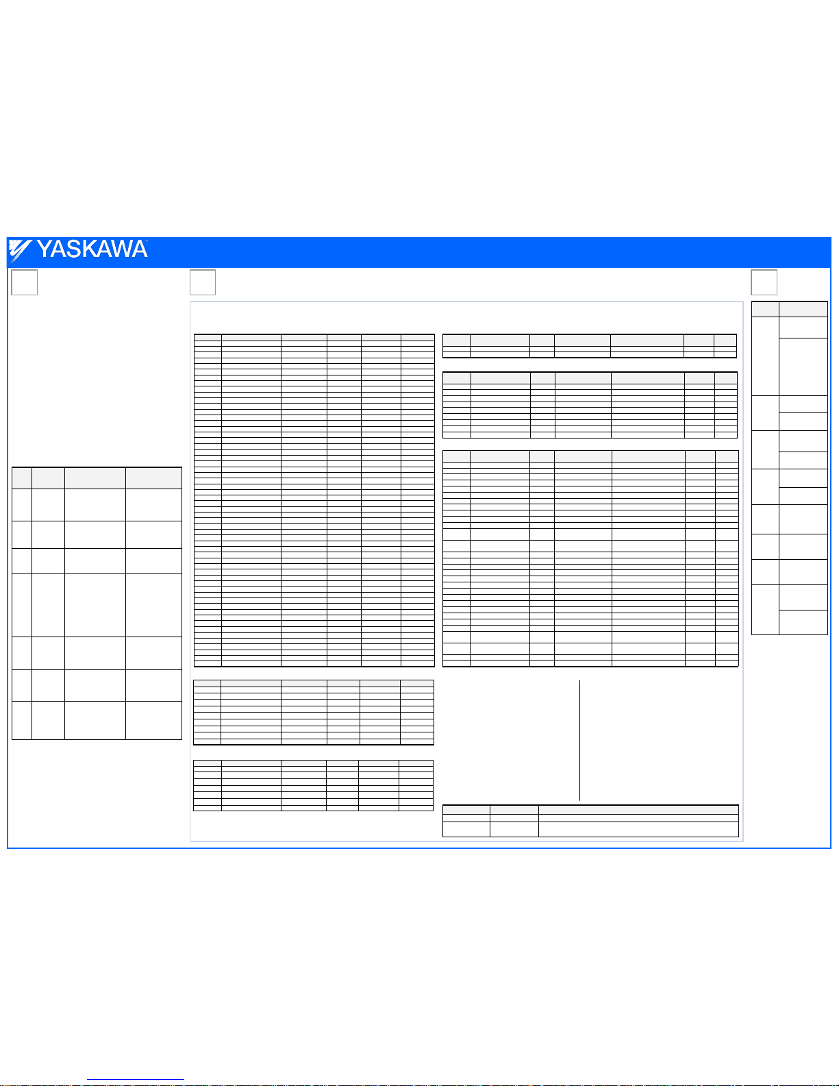
Present Value Access
The Present Value (PV) of BACnet objects can be read. In addition, some PVs can be written or commanded. A commandable PV is similar to writing the value, but the value is actually written into a priority array. The value occupying the highest priority in
the array will be used by the drive. The convention for showing how the PV is accessed is C = Commandable, Value written to a priority array. R = Readable, Value is read-only, W = Writable, Value written to the drive.
Binary Value Objects Analog Outputs Objects
Binary Input Objects
Binary Output Objects
Analog Inputs Objects
Analog Value Objects
Reading Drive Parameters
Reading drive parameters not listed in the analog or digital objects is
accomplished using
AV29 and AV30 as shown below:
1. In decimal, write the desired Modbus register to AV29.
2. In decimal, read the value at the given register from AV30.
For example, to read the Frequency Reference Upper Limit, read
from parameter d2-01. Parameter d2-01 is located at Modbus register
0289H, which is decimal 649.
Set AV29 to “649”
Read AV30 to get the value.
Enter Command
Enter Commands are only required when using AV29 and AV30 to
write drive parameters. An Enter command is not required when
reading or writing to the other BACnet objects.
When writing parameters to the drive from a controller using BACnet
communications, an Enter command must be issued to enable these
parameters. This section describes the types and functions of the
Enter commands.
Accessing Drive Parameters
Writing Drive Parameters
Writing drive parameters not listed in the analog or digital objects is
accomplished using
AV29, AV30, and BV55 or BV56 as shown below:
1. In decimal, write the desired Modbus register to AV29.
2. In decimal, write the value to be written into AV30.
3. At this point the value is pending. One of two actions must be taken to
complete the writing process:
Set BV55 to “ON” to move data to active memory.
Set BV56 to “ON” to move data into active memory and save to non-volatile memory.
For example, to reset the KWH Monitor, write a value of “1” to parameter o1-12.
Parameter o1-12 is located at Modbus register 0512H, which is decimal 1298.
Set AV29 to “1298”
Set AV30 to “1”
Set BV55 to “ON”.
Enter Command Types
The drive supports two types of Enter commands as shown in the table below.
Object ID Object Name
Modbus
Adress
Precision Range Units
PV
Access
AI1 Analog Input 1 Level 004EH XXXX.X – % R
AI2 Analog Input 2 Level 004FH XXXX.X – % R
AI3 Not Used AI3 – – – – –
AI4 Not Used AI4 – – – – –
AI5 Not Used AI5 – – – – –
AI6 Display Format o1-03 0502H XXXXX – – R
AI7 Scale Format b5-20 01E2H XXXXX – – R
AI8 Inverter Model o2-04 0508F XXXXX – – R
AI9 Rated Current n9-01 05D0H XXXX.X – Amps R
Object ID Object Name
Modbus
Adress
Precision Range Units
PV
Acess
AO1 Analog Output 1 Level 0007H XXXX.X 0 to 100.0 % C
AO2 Analog Output 2 Level 0008H XXXX.X 0 to 100.0 % C
Object ID Object Name
Modbus
Adress
Precision Range Units
PV
Access
AV1 Operati on Cmd 0001H XXXXX 0 to 65535 – C
AV2 Frequenc y Cmd 0002H XXX.XX Dep. on o1-03 0.00 to 600.00 Hz (o1-03) C
AV3 PI Setp oint Cmd 0006H XXX.XX 0.00 to 100.00 % C
AV4 MF Outp ut 1 Cmd 0009H XXXXX 0 to 65535 – C
AV5 Ref erence Select Cmd 000FH XXXXX – – C
AV6 Drive St atus 0020H XXXXX – – R
AV7 Fault Deta ils 0021H XXXXX – – R
AV8 Data Link Status 0022H XXXXX – – R
AV9 Frequenc y Reference 0040H XXX.XX Dep. on o1 -03 – Hz (o1-03) R
AV10 Output Frequency 0041H XXX.XX Dep. on o1-03 – Hz (o1-03) R
AV11 Output Voltage 0045H XXXX.X – Volts R
AV12 Output Current 0042H
XXXX.X (>11 kVA)
XXX.XX (<=11 kVA)
– Amps R
AV13 Output Power 0047H
XXXX.X (>11 kVA)
XXX.XX (<=11 kVA)
– Watts R
AV14 Torque Reference 0048H XXXX.X – % R
AV15 MF Input Status 002BH XXXXX – – R
AV16 Drive Status 2 002CH XXXXX – – R
AV17 MF Output Status 002DH XXXXX – – R
AV18 DC Bus Voltage 0031H XXXX.X – Volts R
AV19 PI Feedback Level 0038H XXXX.X – % R
AV20 PI Input Level 0039H XXXX.X – % R
AV21 PI Output Level 003AH XXXX.X – % R
AV22 CPU Software 005BH XXXXX – – R
AV23 Flash Number 004DH XXXXX – – R
AV24 Comm Error Detail 003DH XXXXX – – R
AV25 kVA Setting 0508H XXXXX – – R
AV26 Control Method 0102H XXXXX – – R
AV27 Accel Time 0200H
XXXX.X (C1-10 = 1)
XXX.XX (C1-10 = 0)
0.0 to 6000.0 (C1-10=1)
0.00 to 600.00 (C1-10 = 0)
Sec W
AV28 Decel Time 0201H
XXXX.X (C1-10 = 1)
XXX.XX (C1-10 = 0)
0.0 to 6000.0 (C1-10=1)
0.00 to 600.00 (C1-10 = 0)
Sec W
AV29 Parameter Number – XXXXX 0 to FFFF H – W
AV30 Parameter Data – XXXXX 0 to FFFFH – W
Object ID Object Name Modbus Address Active Text Inactive Text PV Access
BI1 Input Terminal 1 002BH:bit 0 ON OFF R
BI2 Input Terminal 2 002BH:bit 1 ON OFF R
BI3 Input Terminal 3 002BH:bit 2 ON OFF R
BI4 Input Terminal 4 002BH:bit 3 ON OFF R
BI5 Input Terminal 5 002BH:bit 4 ON OFF R
BI6 Input Terminal 6 002BH:bit 5 ON OFF R
BI7 Input Terminal 7 002BH:bit 6 ON OFF R
BI8 Multi-Function Out 1 0020H:bit 5 ON OFF R
BI9 Multi-Function Out 2 0020H:bit 6 ON OFF R
Object ID Object Name Modbus Address Active Text Inactive T ext PV Access
BO1 MF Output M1 -M2 0009H:bit 0 ON OFF C
BO2 MF Output M3 -M4 0009H:bit 1 ON OFF C
BO3 MF Output M5 -M6 0009H:bit 2 ON OFF C
BO4 Ref Sel:PI Setpoint 000FH:bit 1 ON OFF C
BO5 Ref Sel:Term S5 IN 0001H:bit 8 ON OFF C
BO6 Ref Sel:Term S6 IN 0001H:bit 9 ON OFF C
BO7 Refl Sel:Term S7 IN 0001H:bit 10 ON OFF C
Object ID Object Name Modbus Address Active Text Inactive Text PV Access
BV1 Run FW D Cmd 0001H:bit 0 RUN OFF C
BV2 Run REV Cm d 0001H:bit 1 REV OFF C
BV3 Ext Fault Cm d 0001H:bit 2 FAULT OFF C
BV4 Fault Reset Cm d 0001H:bit 3 RESET OFF C
BV5 Com Net Cmd 0001H:bit 4 COM LOCAL C
BV6 Com Cntrl Cmd 0001H:bit 5 COM LOCAL C
BV7 MF Input 3 Cm d 0001H:bit 6 ON OFF C
BV8 MF Input 4 Cm d 0001H:bit 7 ON OFF C
BV9 MF Input 5 Cm d 0001H:bit 8 ON OFF C
BV10 MF Input 6 Cmd 0001H:bit 9 ON OFF C
BV11 MF Input 7 Cmd 0001H:bit 10 ON OFF C
BV12 Set Fault Contact Cmd 0009H:bit 6 ENABLE OFF C
BV13 RUN-STOP 0020H:bit 0 RUN OFF R
BV14 REV-FWD 0020H:bit 1 REV FWD R
BV15 READY 0020H:bit 2 READY OFF R
BV16 FAULT 0020 H:bit 3 FAULTED OFF R
BV17 Data Set Error 0020H:bit 4 ERROR OFF R
BV18 Overcurrent – Gnd Fault 0021H:bit 0 OC-GF OFF R
BV19 Main Ckt Overvoltage 0021H:bit 1 OV OFF R
BV20 Drive Overload 0021H:bit 2 OL2 OFF R
BV21 Drive Overheat 0021H:bit 3 OH1- OH2 OFF R
BV22 Fuse Blown 0021H:bit 5 PUF OFF R
BV23 PI Feedback Loss 0021H:bit 6 FBL OFF R
BV24 External Fault 0021H:bit 7 EF0-EF OFF R
BV25 Hardware Error 0021H:bit 8 CPF OFF R
BV26 Mtr Ovrld-OvrTorque 0021H:bit 9 OL1 -OL3 OFF R
BV27 Overspeed 0021H:bit 10 OS-DEV OF F R
BV28 Main Ckt Undervoltage 0021H:bit 11 UV OFF R
BV29 MCU, Cntl Pwr Sy Err 0021H:bit 12 UV1-2-3 OFF R
BV30 Output Phase Loss 0021H:bit 13 LF OFF R
BV31 Communication Error 0021H:bit 14 CE OFF R
BV32 Operator Disconnect 0021H:bit 15 OPR OFF R
BV33 Operating 002CH:bit 0 OPERATING OFF R
BV34 Zero Speed 002CH:bit 1 ON OFF R
BV35 Frequency Agree 002CH:bit 2 ON OFF R
BV36 Desired Freq Agree 002CH:bit 3 ON OFF R
BV37 Frequency Detect 1 002CH:bit 4 ON O FF R
BV38 Frequency Detect 2 002CH:bit 5 ON O FF R
BV39 Drv Startup Complete 002CH:bit 6 ON OFF R
BV40 Low Voltage Detect 002CH:bit 7 ON OFF R
BV41 Base Block 002CH:bit 8 ON OFF R
BV42 Frequency Ref Mode 002CH:bit 9 COM LOCAL R
BV43 Run Command Mode 002CH:bit 10 COM LOCAL R
BV44 Overtorque Detect 002CH:bit 11 ON OFF R
BV45 Frequency Refer Lost 002CH:bit 12 ON OFF R
BV46 Retry Error 002CH:bit 13 ON OFF R
BV47 Modbus Comms Error 002CH:bi t 14 ON OFF R
BV48 Modbus Timeout Error 002CH:bit 15 ON OFF R
BV49 CRC Error 003DH:bit 0 ON O FF R
BV50 Invalid Data Length 003DH:bit 1 ON OFF R
BV51 Parity Error 003DH:bit 3 ON OFF R
BV52 Overrun Error 003DH:bit 4 ON OFF R
BV53 Framing Error 003DH:bit 5 ON OFF R
BV54 Timeout Error 003DH:bit 6 ON OFF R
BV55 Parameter Accept 0910H:bit 0 ON OFF W
BV56 Param eter Enter 0900H:bit 0 ON OFF W
BV57 Drive Comms Error - ON OFF R
BACnet Object Modbus Address Descript ion
BV55 (Write “ON”) 0910H (bit 0) Writes data in the active RAM onl y. Parameter changes are lost when the drive is shut off.
BV56 (Write “ON”) 0900H (bit 0)
Simultaneously writes data into the EEPROM (non-volatile memory) of the drive and enables the data in active RAM. Parameter changes remain after cycling power.
Error
Codes
Step
6
Display Description
bUS
Option
Communication
Error.
The connection
was lost after establishing initial
communication.
Only detected when
the run command
frequency
reference is
assigned to an
option card.
EFO
Option Card
External Fault.
An external fault
condition is
present.
oFA00
Option Card Connection Error at
Option Port CN5-A.
Option compatibility
error.
oFA01
Option Card Fault
at Option Port
CN5-A.
Option not properly
connected.
oFA03 to
oFA06,
oFA10,
oFA11
Option Card Error
Occurred at Option
Port CN5-A.
oFA12 to
oFA17
Option Card Connection Error
(CN5-A).
oFA30 to
oFA43
Communication
Option Card Connection Error
(CN5-A).
CALL
Serial
Communication
Transmission Error.
Communication has
not yet been
established.
Yaskawa America, Inc., 2121 Norman Drive South, Waukegan, IL 60085, (800) YASKAWA (927-5292) Fax (847) 887-7310, [email protected], www.yaskawa.com, Document Number: TM.BACnet.01 11/28/2012 © Yaskawa America,
 Loading...