

SGMCS
Features Application Examples
1Directly coupled to a load without a mechanical
1Semiconductor equipment
transmission such as a gear.
1LCD manufacturing equipment
1Powerful and smooth operation throughout the speed
range from low to high.
(Instantaneous peak torque: 6 to 600 N·m
maximum speed: 250 to 500 min
-1
)
1High-resolution, 20-bit encoder for highly precise
indexing.
1Units for inspection and testing
1Electronic parts assembling
machines
1IC handlers
1Inspection units for integrated
1Easy wiring and piping with the hollow structure.
circuits
1Automated machines
1Robots
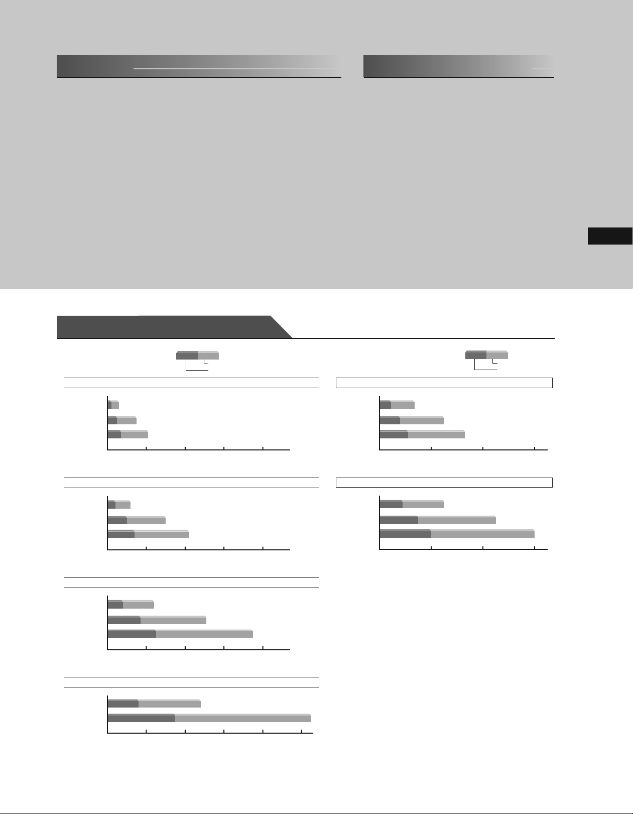
Rated Torque / Peak Torque
1Small-capacity 1Medium-capacity
Outer Diameter
135
mm, Inner Diameter 20 mm
Inst. Peak Torque
Rated Torque
Outer Diameter
280
mm, Inner Diameter 75 mm
Inst. Peak Torque
Rated Torque
Direct Drive Servomotors
SGMCS-02B
05
B
SGMCS-
07
B
SGMCS-
Outer Diameter
SGMCS-04C
10
SGMCS-
C
14
SGMCS-
C
Outer Diameter
SGMCS-08D
17
D
SGMCS-
25
D
SGMCS-
Outer Diameter
(
Rated Torque 2.0 / Inst. Peak Torque 6.0 N・m
)
(
5.0/15.0
)
(
7.0/21.0
20 40 60 80
175
mm, Inner Diameter 35 mm
(
)
4.0/12.0
)
(
10.0/30.0
(
14.0/42.0
20 40 60 80
230
mm, Inner Diameter 60 mm
(
)
8.0/24.0
(
20 40 60 80
290
mm, Inner Diameter 75 mm
)
17.0/51.0
)
SGMCS-45M
80
SGMCS-
1
AM
SGMCS-
M
N・m
Outer Diameter
SGMCS-80N
1
SGMCS-
EN
2
SGMCS-
ZN
N・m
)
(
)
25.0/75.0
(
Rated Torque
45
/ Inst. Peak Torque
(
)
80/240
(
110/330
200 400 600
360
mm, Inner Diameter
(
)
80/240
200 400 600
)
118
135
mm
(
150/450
N・m
(
200/600
)
N・m
)
)
N・m
N・m
SGMCS-16E
35
SGMCS-
(
)
16.0/48.0
E
20 40 60 80 100
(
35.0/105.0
)
N・m
102
103
Ratings and Specifications
1Small-capacity Series
Time Rating: Continuous
Vibration Class: V15
Insulation Resistance: 500 VDC, 10 M
Ω min.
Ambient Temperature: 0 to 40˚C
Excitation: Permanent magnet
Mounting: Flange method
Thermal Class: A
Voltage 200 V VV
Servomotor Model SGMCS-¡¡¡¡¡
Rated Output
Rated Torque
*1
*1, *2
W 42 105 147 84 209 293 168 356 393 335 550
N·m 2.0 5.0 7.0 4.0 10.0 14.0 8.0 17.0 25.0 16.0 35.0
02B¡C 05B¡C 07B¡C 04C¡C 10C¡C 14C¡C 08D¡C 17D¡C 25D¡C 16E¡B 35E¡B
Instantaneous Peak Torque*1N·m 6.0 15.0 21.0 12.0 30.0 42.0 24.0 51.0 75.0 48.0 105
Stall Torque
Rated Current
Instantaneous Max. Current*1A
Rated Speed
Max. Speed
Torque Constant N·m/A
Rotor Moment of Inertia
*1
*1
*1
*1
N·m 2.05 5.15 7.32 4.09 10.1 14.2 8.23 17.4 25.4 16.5 35.6
A
rms
rms
-1
min
-1
min
rms
×10-4 kg·m
1.8 1.7 1.4 2.2 2.2 2.8 1.9 2.5 2.6 3.3 3.5
5.4 5.1 4.1 7.0 7.0 8.3 5.6 7.5 8.0 9.4 10.0
200 200 200 150 200 150
500 500 400 300 500 350 250 500 250
1.18 3.17 5.44 2.04 5.05 5.39 5.1 7.8 10.8 5.58 11.1
2
28 51 77 77 140 220 285 510 750 930 1430
Rated Power Rate*1kW/s 1.4 4.9 6.4 2.1 7.1 8.9 2.2 5.7 8.3 2.75 8.57
Rated Angular Acceleration*1rad/s
Absolute Accuracy second
Repeatability second
Applicable SERVOPACK
*1: These items and torque-motor speed characteristics quoted in combination with an SGDV SERVOPACK are at an armature winding temperature of 100˚C. Other values
quoted at 20˚C.
*2: Rated torques are continuous allowable torque values at 40˚C with a steel heat sink attached.
Heat sink: SGMCS-¡¡B : 350 mm
SGMCS-¡¡D : 550 mm
Notes: 1 SGMCS servomotor with holding brake is not available.
2 For the bearings used in SGMCS servomotors, loss varies according to the bearing temperature. At low temperatures, the amount of heat loss will be large.
1
Small-capacity Series: Torque-Motor Speed Characteristics
SGMCS-02B
)
500
-1
min
400
(
300
200
A
100
Motor Speed
0
1
0
.53.04.56.07.
Torque (N・m
SGMCS-
)
500
-1
400
min
(
300
200
A
100
Motor Speed
0
0
612182430
Torque (N・m
SGMCS-
)
500
-1
400
min
(
300
200
A
100
Motor Speed
0
15 30 45 60 75
0
Torque (N・m
Notes: 1 The solid, dotted lines of the intermittent duty zone indicate the characteristics when a servomotor runs with the following combinations:
· The solid line: With a three-phase 200 V SERVOPACK
· The dotted line: With a single-phase 100 V SERVOPACK
2 When the effective torque during intermittent duty is within the rated torque, the servomotor can be used within the intermittent duty zone.
3 When the main circuit cable length exceeds 20 m, note that the intermittent duty zone of the Torque-Motor Speed Characteristics will shrink as the line-to-line voltage drops.
2
710 980 910 520 710 640 280 330 330 170 240
±15 ±15 ±15 ±15
±1.3 ±1.3 ±1.3 ±1.3
SGDV-¡¡¡¡
2R8A 2R8A 2R8A 5R5A
× 350 mm × 12 mm SGMCS-¡¡C : 450 mm × 450 mm × 12 mm
× 550 mm × 12 mm SGMCS-¡¡E : 650 mm × 650 mm × 12 mm
)
-1
min
(
B
5
)
10
C SGMCS-14C SGMCS-08D SGMCS-17D
B
)
25
D SGMCS-16E SGMCS-35E
B
)
Motor Speed
)
-1
min
(
Motor Speed
)
-1
min
(
Motor Speed
SGMCS-
500
400
300
200
A
100
0
0
3691215
500
400
300
200
A
100
0
0
10 20 30 40 50
500
400
300
200
A
100
0
0
918273645
Torque (N・m
B
Torque (N・m
Torque (N・m
Withstand Voltage: 1500 VAC for one minute
Enclosure: Totally enclosed, self-cooled, IP42 (except for gaps on the rotating
section of the shaft)
Ambient Humidity: 20% to 80% (no condensation)
Drive Method: Direct drive
Rotation Direction: Counterclockwise (CCW) with forward run reference when
viewed from the load side
A
: Continuous Duty Zone B: Intermittent Duty Zone
05
B
B
)
)
B
)
)
500
-1
400
min
(
300
200
A
100
Motor Speed
0
0
)
500
-1
400
min
(
300
200
A
100
Motor Speed
0
0
)
500
-1
400
min
(
300
200
A
100
Motor Speed
0020 40 60 80 100
07
SGMCS-
510152025
612182430
B
Torque (N・m
B
Torque (N・m
B
Torque (N・m
B
)
)
)
)
500
-1
400
min
(
300
200
100
Motor Speed
0
)
500
-1
400
min
(
300
200
100
Motor Speed
(Note2)
04
SGMCS-
A
3691215
0
Torque (N・m
A
0012 24 36 48 60
C
B
B
Torque (N・m
)
)

Direct Drive Servomotors
SGMCS
Ratings and Specifications
1Medium-capacity Series
Time Rating: Continuous
Vibration Class: V15
Insulation Resistance: 500 VDC, 10 M
Ω min.
Ambient Temperature: 0 to 40˚C
Excitation: Permanent magnet
Mounting: Flange method
Thermal Class: F
Voltage 200 V
Servomotor Model SGMCS-¡¡¡¡¡
Rated Output
Rated Torque
*1
*1, *2
W 707 1260 1730 1260 2360 3140
N·m 45 80 110 80 150 200
45M¡ 80M¡ 1AM¡ 80N¡ 1EN¡ 2ZN¡
Instantaneous Peak Torque*1N·m 135 240 330 240 450 600
Stall Torque
Rated Current
Instantaneous Max. Current*1A
Rated Speed
Max. Speed
Torque Constant N·m/A
Rotor Moment of Inertia
*1
*1
*1
*1
N·m 45 80 110 80 150 200
A
rms
rms
-1
min
-1
min
×
10-4 kg·m
rms
5.80 9.74 13.4 9.35 17.4 18.9
17 28 42 28 56 56
8.39 8.91 8.45 9.08 9.05 11.5
2
388 627 865 1360 2470 3060
Rated Power Rate*1kW/s 52.2 102 140 47.1 91.1 131
Rated Angular Acceleration*1rad/s
Applicable SERVOPACK
*1: These items and torque-motor speed characteristics quoted in combination with an SGDV SERVOPACK are at an armature winding temperature of 20˚C.
*2: Rated torques are continuous allowable torque values at 40˚C with a steel heat sink attached.
Heat sink: 750 mm
Notes: 1 SGMCS servomotor with holding brake is not available.
2 For the bearings used in SGMCS servomotors, loss varies according to the bearing temperature. At low temperatures, the amount of heat loss will be large.
2
SGDV-¡¡¡¡
× 750 mm × 45 mm
1160 1280 1270 588 607 654
7R6A 120A 180A 120A 200A 200A
Withstand Voltage: 1500 VAC for one minute
Enclosure: Totally enclosed, self-cooled, IP44
(except for shaft opening)
Ambient Humidity: 20% to 80% (no condensation)
Drive Method: Direct drive
Rotation Direction: Counterclockwise (CCW) with forward run reference when
viewed from the load side
150
300 250
Rotary Motors
Direct Drive Servomotors
1
Medium-capacity Series: Torque-Motor Speed Characteristics
SGMCS-45M SGMCS-80M
300
)
-1
min
(
200
100
A
Motor Speed
0
0 50 100 150
Torque (N・m
SGMCS-1EN SGMCS-2ZN
300
)
-1
min
200
(
100
A
0
Motor Speed
0 100 200 300 400 500
Notes: 1 When the effective torque during intermittent duty is within the rated torque, the servomotor can be used within the intermittent duty zone.
2 When the main circuit cable length exceeds 20 m, note that the intermittent duty zone of the Torque-Motor Speed Characteristics will shrink as the line-to-line voltage drops.
Torque (N・m
B
)
B
)
300
)
-1
min
(
200
100
A
Motor Speed
0
0 100 200 300
Torque (N・m
300
)
-1
min
200
(
100
A
0
Motor Speed
0 200 400 600 800
Torque (N・m
A
: Continuous Duty Zone B: Intermittent Duty Zone
SGMCS-1AM SGMCS-80N
300
)
-1
min
200
(
B
)
B
)
100
A
0
Motor Speed
0 100 200 300 400
Torque (N・m
B
)
(Note1)
300
)
-1
min
200
(
100
A
0
Motor Speed
0 100 200 300
Torque (N・m
B
)
104

Ratings and Specifications
1Allowable Load Moment of Inertia at the Motor Shaft
Allowable Load Moment of Inertia
(Rotor Moment of Inertia Ratio)
SGMCS-
Servomotor Model
02B¡C, 05B¡C, 07B¡C, 04C¡C 2.0, 5.0, 7.0, 4.0 10 times
10C¡C 10.0 5 times
14C¡C, 08D¡C, 17D¡C, 25D¡C, 16E¡B, 35E¡B 14.0, 8.0, 17.0, 25.0, 16.0, 35.0 3 times
45M¡A, 80M¡A, 1AM¡A, 80N¡A, 1EN¡A, 2ZN¡A 45, 80, 110, 150, 200 3 times
Rated Torque
N·m
1Load Moment of Inertia
The larger the load moment of inertia, the worse the movement response.
The allowable load moment of inertia (
moment of inertia of each servomotor (
on servomotor drive conditions.
Use the AC servo drive capacity selection program SigmaJunmaSize+ to check the operation conditions. The program
can be downloaded for free from our web site (http://www.e-mechatronics.com/).
An overvoltage alarm (A.400) is likely to occur during deceleration if the load moment of inertia exceeds the allowable load
moment of inertia. SERVOPACKs with a built-in regenerative resistor may generate a regenerative overload alarm
(A.320). Take one of the following steps if this occurs.
· Reduce the torque limit.
· Reduce the deceleration rate.
· Reduce the maximum speed.
· Install an external regenerative resistor if the alarm cannot be cleared using the steps above. Refer to Regenerative
Resistors on page 293.
JL) depends on motor capacity and is limited to within 5 to 30 times the rotor
JM). This value is provided strictly as a guideline and results may vary depending
105

Direct Drive Servomotors
k
SGMCS
Mechanical Specifications
1Allowable Loads
The loads applied while a servomotor is running are roughly classified in the following patterns. Design the machine so that the
thrust load and moment load will not exceed the values in the table.
F
Where F is external force,
Thrust load: Fa
Moment load: M
Servomotor Model
SGMCS-
Dimension A mm 0 0 0 0 33 37.5
Allowable Thrust Load (Fa)
Allowable Moment Load (M)
Note: SGMCS-02B to -35E servomotors, set dimensions A to 0 (zero).
=F+
Load mass
=
0
¡
02B 05B 07B 04C 10C 14C 08D 17D 25D 16E 35E 45M 80M
N 1500 3300 4000 11000 9000 16000
N·m 40 50 64 70 75 90 93 103 135 250 320 180 350
L
F
Where F is external force,
Thrust load: Fa
Moment load: M
=F+
Load mass
=F×
L
F
Where F is external force,
Thrust load: Fa
Moment load: M
=
Load mass
(
=F×
L
L
(
See the table below
A
for the dimension A of
each servomotor model.
)
+
A
1AM
80N 1EN 2ZN
Rotary Motors
)
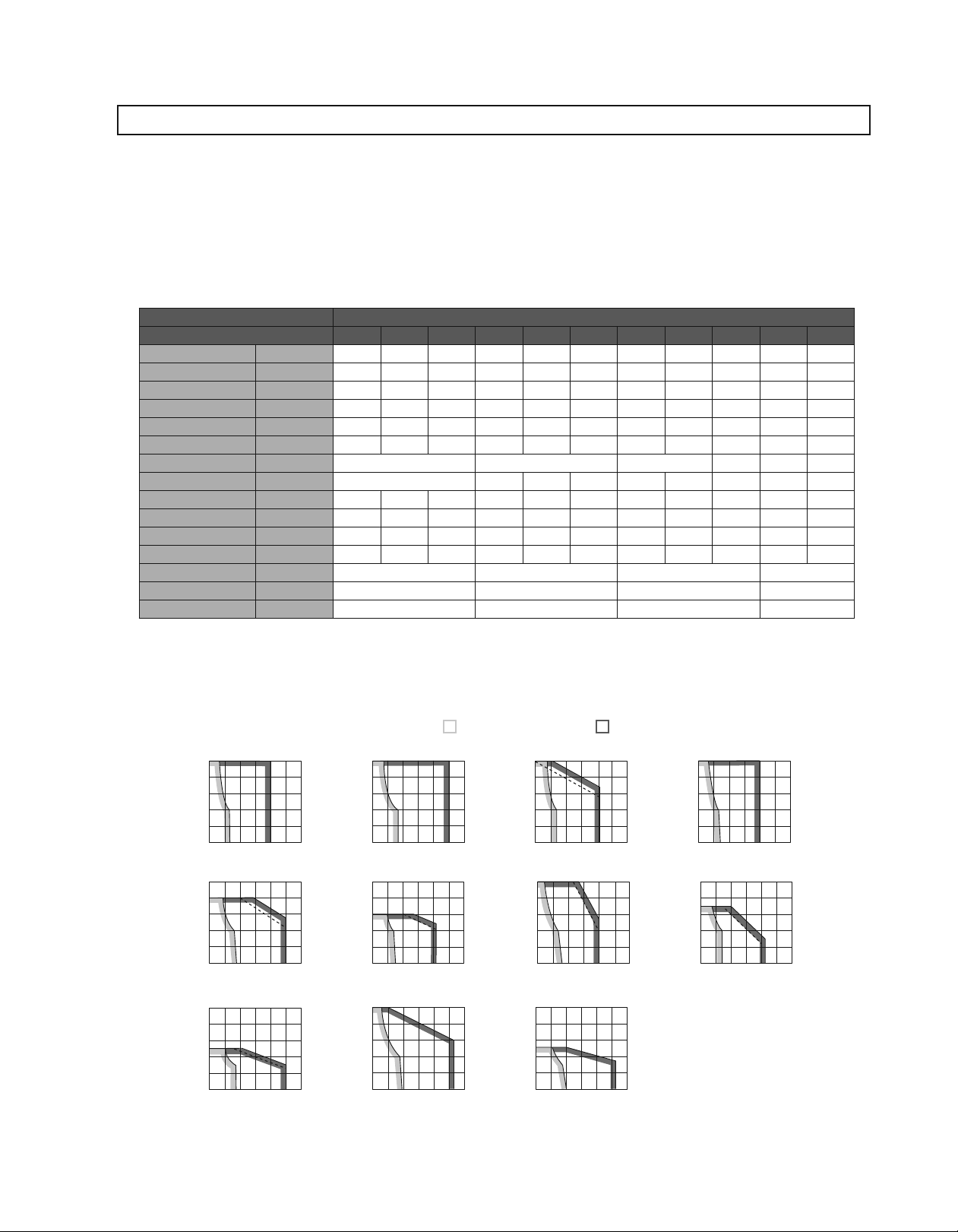
1Mechanical Tolerance
The following table shows tolerances for the servomotor’s output shaft and installation area.
See the dimensional drawing of the individual servomotor for more details on tolerances.
(1) Small-capacity Series
Dia.
¡
Dia.
¡
Drive End
Opposite
Drive End
④
Dia.
A
②
A
(2) Medium-capacity Series
¡
④
Dia.
Drive End
Opposite
Drive End
A
B
A
②
¡
¡
Dia.
Dia.
Dia.
②
B
1Direction of Rotation
Positive rotation of the servomotor
is counterclockwise when viewed
from the load.
①
B
Run-out of the Surface of the Shaft
Run
Perpendicularity between the Flange Face and Output Shaft
③
B
Coaxiality of Output Axis and Mounting Socket Joint
①
Run
Run
B
A
⑤
Perpendicularity between the Flange Face and Output Shaft
Coaxiality of Output Axis and Mounting Socket Joint 0.08 0.08
Right angle between Flange Face and Output Shaft 0.08 0.08
Tolerance T.I.R.
(Total Indicator Reading) Units: mm
-
out at the End of the Shaft 0.04 0.04 0.04 0.04
Tolerance T.I.R.
(Total Indicator Reading) Units: mm
-
out of the Surface of the Shaft 0.02 0.02
-
out at the End of the Shaft 0.04 0.04
02B 05B 07B 04C 10C 14C 08D 17D 25D 16E 35E
0.02 0.02 0.02 0.02
0.07 0.07 0.08 0.08
0.07 0.07 0.08 0.08
1Impact Resistance
Mount the servomotor with the axis
horizontal. The servomotor will withstand the following vertical impacts:
· Impact Acceleration: 490 m/s
· Number of Impacts: 2
Servomotor Model SGMCS-
Servomotor Model SGMCS-
45M 80M 1AM 80N 1EN 2ZN
−−
2
Impact applied
to the servomotor
Direct Drive Servomotors
Vertical
1Vibration Resistance
Mount the servomotor with the axis horizontal. The servomotor will withstand the following vibration acceleration in three directions: Vertical, side to side, and front to
back.
Front to bac
Servomotor Type
Small-capacity Series
Medium-capacity Series
Vibration Acceleration at
Flange
49 m/s
24.5 m/s
2
2
Vertical
Side to Side
Vibration applied to
the servomotor
1Vibration Class
The vibration class at rated motor speed is V15. (A vibration
class of V15 indicates a total vibration amplitude of 15
maximum on the servomotor during rated rotation.)
1Enclosure
Servomotor Type Enclosure
Small-capacity Series
Medium-capacity Series
IP42 (except for gaps on the rotating section of the shaft)
IP44
μ
m
106
 Loading...