

Yaskawa SGMAH Selection Guide
LEGEND System Components
Selecting Your SGMAH LEGEND System
Servomotors
servomotor sizing software, available at no charge. (Request SigmaSize software via e-mail, at:
SGMAH
literature@yaskawa.com).
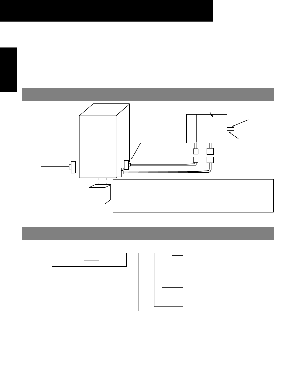
Use the diagram below to locate and identify the components of your system. Each item is
letter-coded and cross-referenced in the option tables on the following pages.
System Configuration
Optional Holding Brake
Shaft Keyway
SGMAH
Servomotor
First, select the AC servomotor suited for your application using SigmaSize: the Yaskawa
(A)
Shaft Seal
Motor si de
Co nn ector (D)
1CN
I/O Signal
Connector
(D)
Regenerative Unit (E)
SGDG Digital
Tor q u e
Amplifie r
(B)
Amplifier
(B)
Co nn ector
Encoder (D )
Encoder side
Co nn ector (D)
2CN
Encoder Cable (C)
Motor Cable (C)
Specify a technical manual, if it is needed, on your
servo system purchase order:
LE GEND Di gital Torque Amplifier User’s Manual: YEA-SIA-LGD-1.2
(Manual is provided at no charge with a purchase order,
but it m ust be re qu ested).
Model Number Designation
SGMAH - 01 A A F 4 1
LEGEND AC Servomotor Type
Rated Output
A3: 30W (0.04hp)
A5: 50W (0.07hp)
01: 100W (0.13hp)
02: 200W (0.25hp)
04: 400W (0.5hp)
08: 750W (1hp)
Power Supply
A: 200V
B: 100V
Accessories
1: Standard
C: Standard with 24V
S: Standard with Shaft Seal *
E: Standard with Brake & Shaft Seal *
Shaft Specifications
4: Straight Shaft with Keyway
2: Straight Shaft without Keyway
Revision Level
F: Standard
N: NEMA Flange ( for 200W, 400W, and
800W without brake only)
Encoder Specifications
A: 13-bit (2048 x 4) Incremental Encoder
*
Keyw ay s, Sh aft S ea ls and H o lding Brakes are not
ava i lable on motors with NEMA flanges.
DC
Brake
1

LEGEND System Components
Servomotor & Amplifier Selection
Use the table below to select the recommended SGMAH LEGEND AC servomotor and amplifier.
Motors Used with 13-bit Increment al Encoders (5000rpm* Maximum) Amplifier
Description
System Voltage
Construction
200V
Straight Shaft with-
out Keyway
200V
Straight Shaft with
Keyway
200V
Straight Shaft
without Keyway
NEMA Flange
100V
Straight Shaft
without Keyway
100V
Straight Shaft
with Keyway
100V
Straight Shaft
without Keyway
NEMA Flange
Peak
Tor que*
(oz • in)
40.5 13.5
67.7 22.6
135 45.1
270 90.1
542 181
1010 338
135 45.1
270 90.1 1.50
542 181 2.45
1010* 338* 9.52
40.5 13.5
67.7 22.6
135 45.1
270 90.1
135 45.1
270 90.1 1.50 SGMAH-02BAAN21***
Rated
Torque *
(oz • in)
Motor Inertia
(oz • in • s
0.235
0.355
0.312
0.432
0.515
0.635
0.515
0.635
1.50
2.321
2.45
3.271
9.52
11.5
0.515
0.635
0.235
0.355
0.312
0.432
0.515
0.635
0.515
0.635
1.50
2.321
0.515
0.635
2
×10-3)
Mot or
M ODEL NUMB ER (A)
SGMAH-A3AAF21
SGMAH-A3AAF2C
SGMAH-A5AAF21
SGMAH-A5AAF2C
SGMAH-01AAF21
SGMAH-01AAF2C
SGMAH-01AAF41
SGMAH-01AAF4C
SGMAH-02AAF41
SGMAH-02AAF4C
SGMAH-04AAF41
SGMAH-04AAF4C
SGMAH-08AAF41
SGMAH-08AAF4C
SGMAH-01AAF21**
SGMAH-01AAF2C**
SGMAH-02AAN21***
SGMAH-04AAN21***
SGMAH-08AAN21**** 10GT*
SGMAH-A3BAF21
SGMAH-A3BAF2C
SGMAH-A5BAF21
SGMAH-A5BAF2C
SGMAH-01BAF21
SGMAH-01BAF2C
SGMAH-01BAF41
SGMAH-01BAF4C
SGMAH-02BAF41
SGMAH-02BAF4C
SGMAH-01BAF21**
SGMAH-01BAF2C**
Notes: 24VDC brakes for SGMAH AC servomotors are standard. Contact a local source for 24VDC power supplies.
Motor power and encoder cables are factory pre-wired with approximately 13” lead length with amplifier mating connectors.
Use the tables on the following pages to specify mating connectors or pre-wired cables available in various lengths.
For technica l inf ormat ion, r eq ue st Yaska wa User’s Manual number Y EA-SIA -LGD-1.2.
* Reference the previously listed sp eed/torque (force) curves for performance with the applied syst em voltage and
phase(s).
** Use NEMA 23 adapter flange (see periphial device selection)
*** NEMA 23 flange and pilot (see SGMAH Dime nsion)
**** NEMA 34 flange and pilot (see SGMAH Dimension)
Ampli fier MODEL NUMBER
(B )*
Singl e-Phase
SGDG
01GT
04GT
10GT
01GT —
04GT
01GT
04GT
3-Phase
SGDG-
—
—
—
—
—
10GT
—
10GT
—
—
—
—
—
—
Motor &
Amplifier
Item Class
Stock
Stock
Stock
Stock
Stock
SGMAH
Servomotors
2
 Loading...