

100/200V Single-phase Sigma II Servo Systems
Selecting Your SGMAH Sigma II Servo System
First, select the Sigma II servomotor suited for your application using SigmaSize: the Yaskawa
servomotor sizing software, available at no charge. (Request SigmaSize software via e-mail, at:
literature@yaskawa.com).
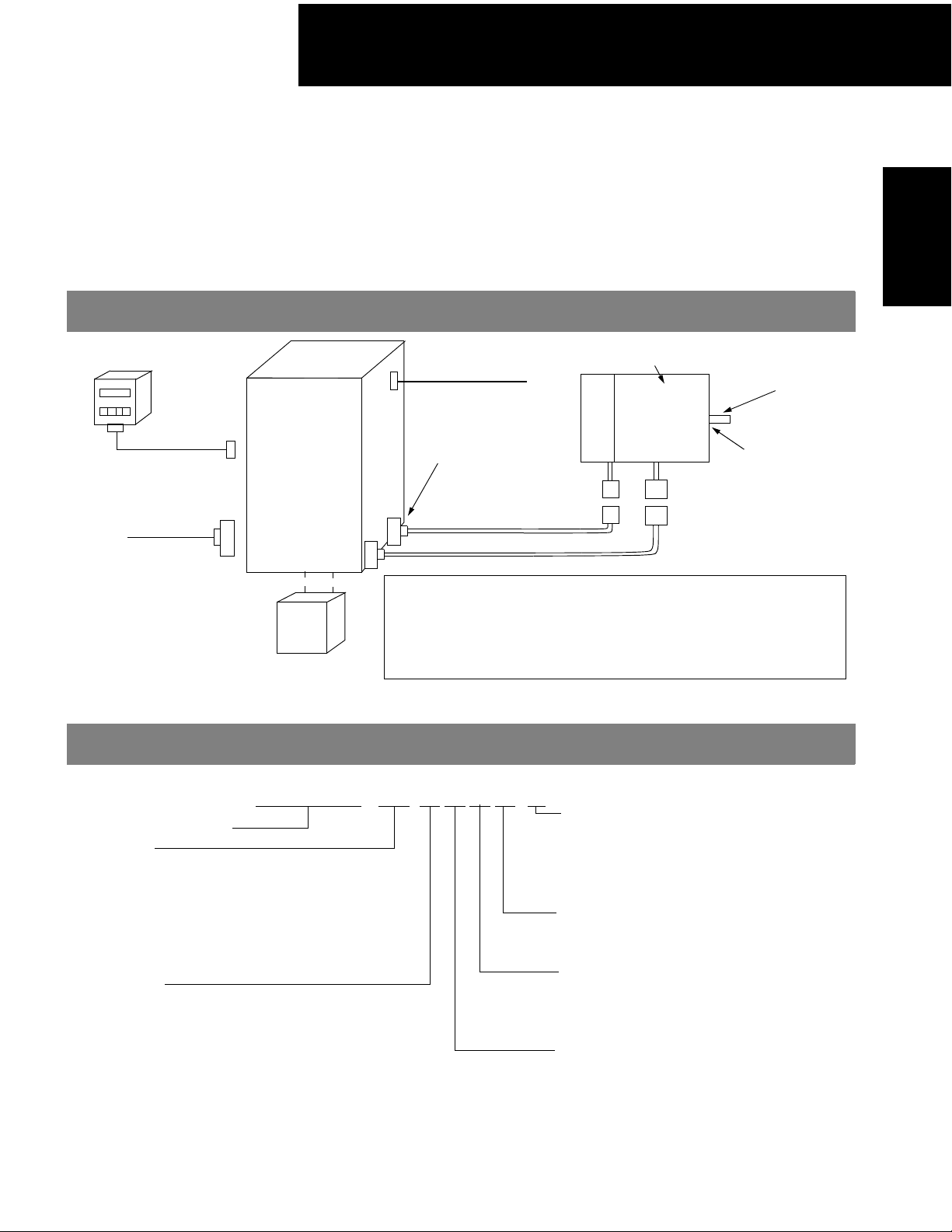
Use the diagram below to locate and identify the components of your system. Each item is lettercoded and cross-referenced in the option tables on the following pages.
System Configuration
SGMAH
Servomotors
Digital Operator (E)
3CN
Peripheral
Signal
Cable (E)
1CN
I/O Signal
Connector
(D)
Regenerative Unit (E)
SGDH Servo
Amplifier
(B)
Model Number Designation
SGMAH - 01 A A F 4 1
Sigma II Servomotor Type
Rated Output
A3: 30W (0.04hp)
A5: 50W (0.07hp)
01: 100W (0.13hp)
02: 200W (0.25hp)
04: 400W (0.5hp)
08: 750W (1hp)
Power Supply
A: 200V
B: 100V
5CN
For Monitor (D)
Connector
Encoder (D)
Encoder side
Connector (D)
2CN
Encoder Cable (C)
Motor Cable (C)
Optional Holding Brake
Shaft Keyway
SGMAH
Servomotor
(A)
Shaft Seal
Motor side
Connector (D)
Specify a technical manual, if it is needed, on your
servo system purchase order:
Sigma II Series Servo System User’s Manual: YEA-SIA-S800-32.2
(Manual is provided at no charge with a purchase order,
but it must be requested).
Accessories
1: Standard
C: Standard with 24V
S: Standard with Shaft Seal*
E: Standard with Brake & Shaft Seal*
Shaft Specifications
4: Straight Shaft with Keyway*
2: Straight Shaft without Keyway
Revision Level
F: Standard
N: NEMA flange (200W, 400W & 800W
only without holding brake)
Encoder Specifications
A: 13-bit (2048 x 4) Incremental Encoder
1: 16-bit (16384 x 4) Absolute Encoder
Brake*
DC
* Keyways, shaft seals, and holding brakes not available on motors with NEMA flanges (revision level = N).
21
 Loading...