

Page 1
External Dimensions Units: mm
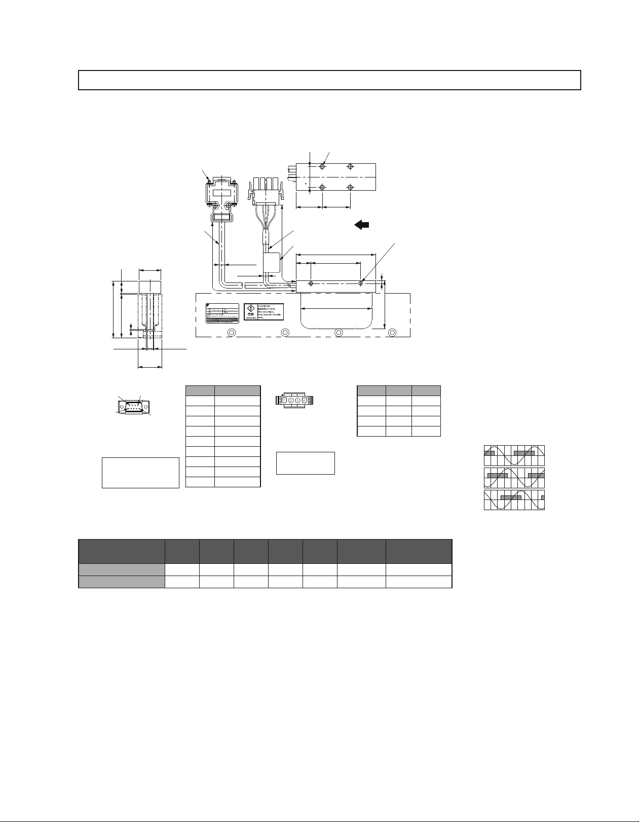
(1) SGLGW-30SGLGW-30
3Moving Coil: SGLGW-30A¡¡¡C¡ (With a connector by Tyco Electronics AMP K.K.)
22
12
1
)
44
57
(
)
1
(
)
G (Gap
G (Gap
24
Hall Sensor
Connector Specifications
Pin Connector:
17
JE-
by DDK Ltd.
The Mating Connector
Socket Connector
:
Stud :
9
5
23090-02
17
17L-002
17L-002C1
JE-
6
1
(D8C
13090-02
C or
)
(D8C
2
-Screws
4-40
UNC
#
Cable
20276
,
UL
26
AWG
)
Pin No. Signal
1
2 Phase U
3 Phase V
4 Phase W
5
6 Not used
7 Not used
)
8 Not used
9 Not used
50
±
(
500
5.3
Dia.
(
5
+
5V (Power supply)
0V (Power supply)
Dia.
50
±
Cable
500
2517
UL
Nameplate
)
15
)
Linear Servomotor
Connector Specifications
Plug : 350779-1
Pin : 350924-1 or
770672-1
by Tyco Electronics AMP K.K.
The Mating Connector
350780-1
Cap :
350925-1
Socket :
770673-1
4-M4
Mounting Screws, Depth
5
17
5
L
4
L
The moving coil moves in the direction indicated by the arrow
, AWG
25
when current flows in the order of phase U, V, and W.
2×2-M4
1
L
3
L
Mounting Screws, Depth 5 on Both Sides
3
5
2
L
.
48
Hall Sensor Output Signals
Pin No. Signal
1
2
3
4 FG Green
or
Phase U
Phase V
Phase W
Wire Color
Red
White
Blue
When the moving coil moves in the
direction indicated by the arrow in
the figure, the relationship between
the hall sensor output signals Su,
Sv, Sw and the inverse power of
each motor phase Vu, Vv, Vw
becomes as shown in the figure
below.
Vu
Su
Inverse
Vv
Power
(V)
Sv
Vw
0 180 360 540
Sw
Electrical Angle ( ˚
)
125
Moving Coil Model
SGLGW-
30A050C¡ 50 48 30 20
L1 L2 L3 L4 L5 G (Gap)
20 0.85 0.14
30A080C¡ 80 72 50 30 25 0.95 0.19
*: The values indicate the mass of moving coil with a hall sensor unit.
Approx. Mass*
kg
Page 2
External Dimensions Units: mm
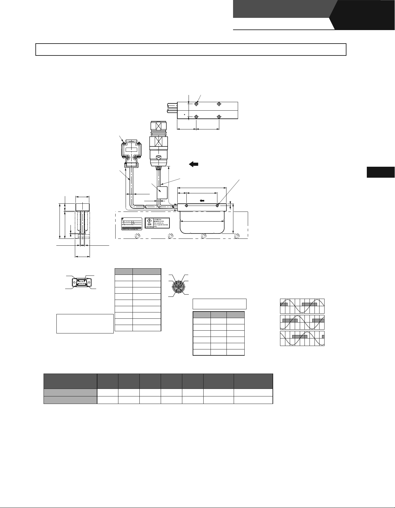
3Moving Coil: SGLGW-30A¡¡¡C¡D (With a connector by Interconnectron GmbH)
M
4
4
-
Mounting Screws, Depth
17
5
50
±
500
Cable
UL
15
L
2517
2
-Screws
4-40
#
UNC
Cable
UL
20276
, AWG
26
Name
plate
50
±
(
)
5.3
22
12
500
Dia
(
5
Dia
)
1
)
44
57
)
(
1
(
4
L
The moving coil moves in the direction
indicated by the arrow when current flows
in the order of phase U, V, and W.
25
,AWG
1
L
3
L
3
5
2
L
.
48
Linear Servomotors
SGLGW
5
×
2-M4
2
Mounting Screws, Depth 5 on Both Sides
(Coreless Type)
Linear
Linear Servomotors
G (Gap
)
G (Gap
)
24
Hall Sensor
Connector Specifications
9
5
Pin Connector :
17
23090-02
JE-
by DDK Ltd.
The Mating Connector
Socket Connector :
17
JE-
Stud :
13090-02
17L-002
C or
17L-002C1
(D8C
Moving Coil Model
SGLGW-
30A050C¡D
)
)
Pin No. Signal
+
1
5V (Power supply)
2 Phase U
3 Phase V
4 Phase W
0V (Power supply)
5
6 Not used
7 Not used
8 Not used
9 Not used
6
1
(D8C
L1 L2 L3 L4 L5
50 48 30
Linear Servomotor
Connector Specifications
2
1
6
Extension: SROC06JMSCN
3
Pin :
021.423.1020
by Interconnectron GmbH
4
5
The Mating Connector
: SPUC06KFSDN
Plug
020.030.1020
Socket:
Pin No. Signal
1
Phase U
Phase V
2
Phase W
3
Not used
4
Not used
5
6 FG Green
G
(Gap)
20 20 0.85 0.14
30A080C¡D 80 72 50 30 25 0.95 0.19
*: The values indicate the mass of moving coil with a hall sensor unit.
236
Wire Color
Red
White
Blue
–
–
Approx. Mass*
169
Hall Sensor Output Signals
When the moving coil moves in the direction indicated by the arrow in the figure, the
relationship between the hall sensor output
signals Su, Sv, Sw and the inverse power of
each motor phase Vu, Vv, Vw becomes as
shown in the figure below.
Vu
Su
Inverse
Power
(V)
Vv
Sv
Vw
0 180 360 540
Electrical Angle
kg
Sw
(
)
°
126
Page 3
External Dimensions Units: mm
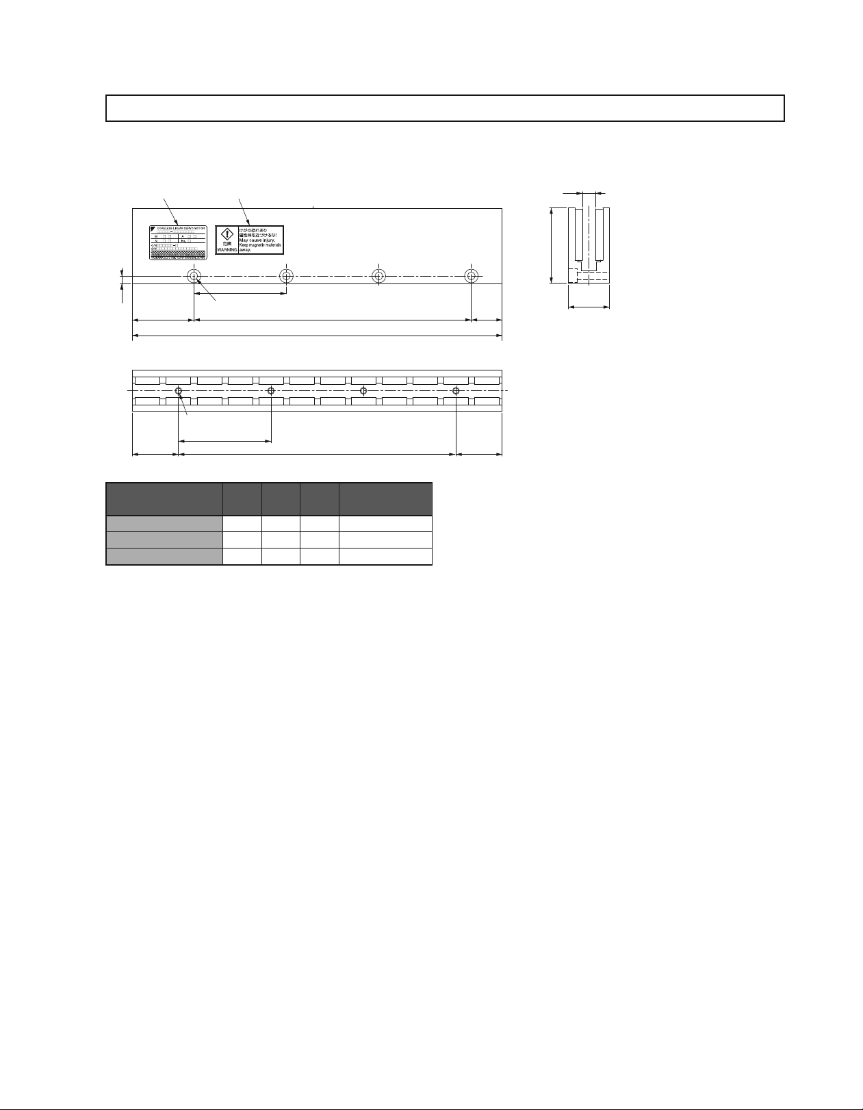
3Magnetic Way: SGLGM-30: SGLGM-30 SGLGM-30SGLGM-30¡¡¡A
5
.
4
Nameplate
36
Warning Label
45
Pitch
N-4.5 Dia. Mounting Holes (Per unit
8
Dia. Counter Boring, Depth 5 on Both Sides.
L1 (Unit
7.6
44
)
(18)
2
1
-0.
)
3
-0.
L
24
N-M4 Mounting Screws, Depth
Pitch
27
Magnetic Way Model
SGLGM-
6
54
L1 L2 N
2
L
(27)
Approx. Mass
kg
30108A 108 54 2 0.6
30216A
30432A 432
Note: If you have a pacemaker or any other electronic medical device, do not go near the magnetic way of the linear servomotor.
216 162 4 1.1
378 8 2.3
127
Page 4
Linear Servomotors
SGLGW
External Dimensions Units: mm
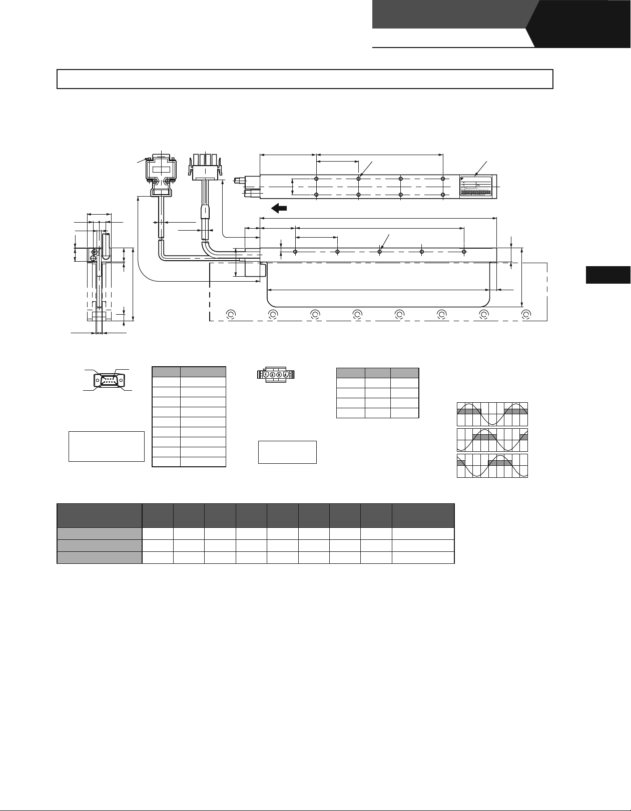
(2) SGLGW-402) SGLGW-40) SGLGW-40SGLGW-40
3Moving Coil: SGLGW-40A¡¡¡C¡ (With a connector by Tyco Electronics AMP K.K.)
6
2
-Screws
#4-40 UNC
5
L
45
L
Mounting Holes
N2-M4 Tapped Holes, Depth
(Coreless Type)
Linear
Nameplate
6
25.4
7
2
5
6
.
4
8
.
5
.
0
14
.
15
1
7
8
Gap 0.
8
Gap 0.
Hall Sensor
Connector Specifications
9
5
Pin Connector :
17
23090-02
JE-
by DDK Ltd.
The Mating Connector
Socket Connector :
17
JE-
17L-002
Stud :
17L-002C1
(D8C
13090-02
C or
6
1
)
(D8C
50
±
500
78
)
(
)
5.3
Dia.
(
)
7
Dia.
Pin No. Signal
+
1
5V (Power supply)
2 Phase U
3 Phase V
4 Phase W
0V (Power supply)
5
6 Not used
7 Not used
8 Not used
9 Not used
50
±
500
16
4
L
4
30
Linear Servomotor
Connector Specifications
Plug : 350779-1
Pin : 350561-3 or
350690-3 (No.1 to 3)
350654-1
350669-1 (No.4)
by Tyco Electronics AMP K.K.
The Mating Connector
Cap :
Socket :
17
The moving coil moves in the direction indicated by the arrow when current flows in the order of phase U, V, and W.
45
Pin No. Signal
350780-1
350570-3
or
350689-3
1
L
3
L
Mounting Holes on Both Sides
1-M4
N
2
L
Wire Color
1
Phase U
Red
Phase V
Phase W
White
Blue
2
3
4 FG Green
Tapped Holes, Depth
Inverse
Power
(V)
6
Hall Sensor Output Signals
When the moving coil moves in the direction indicated by the arrow in the figure, the
relationship between the hall sensor output
signals Su, Sv, Sw and the inverse power of
each motor phase Vu, Vv, Vw becomes as
shown in the figure below.
Vu
Su
Vv
Vw
0 180 360 540
15
(
)
7.5
Sv
Sw
Electrical Angle
63
(
°
Linear Servomotors
)
Moving Coil Model
SGLGW-
40A140C¡ 140 125 90 30
L1 L2 L3 L4 L5 L6 N1 N2
52.5 45 3 4 0.40
40A253C¡ 252.5 237.5 180 37.5 60 135 5 8 0.66
40A365C¡ 365 350 315 30 52.5 270 8 14 0.93
*: The values indicate the mass of moving coil with a hall sensor unit.
Approx. Mass*
kg
128
Page 5

External Dimensions Units: mm
3Moving Coil: SGLGW-40A¡¡¡C¡D (With a connector by Interconnectron GmbH)
2
-Screws
#4-40 UNC
5
L
45
L
Mounting Screws,
N
6
2-M4
Tapped Holes, Depth
Name plate
6
25.4
5
6
.
8
4
.
5
.
0
7
14
Gap 0.
8
Gap 0.
Hall Sensor
Connector Specifications
9
5
Pin Connector :
17
23090-02
JE-
by DDK Ltd.
The Mating Connector
Socket Connector :
17
13090-02
JE-
17L-002
Stud :
17L-002C1
50
±
50
±
2
.
500
(
5.3
Dia.
(
7
Dia.
500
)
)
16
17
The moving coil moves in the direction indicated by the arrow when current flows in the order of phase U, V, and W.
4
L
4
45
1
L
3
L
Mounting Holes on Both Sides
1-M4
Tapped Holes, Depth
N
6
15
15
1
78
30
2
L
(
7.5
63
)
7
8
Hall Sensor Output Signals
When the moving coil moves in the direction indicated by the arrow in the figure, the
relationship between the hall sensor output
signals Su, Sv, Sw and the inverse power of
each motor phase Vu, Vv, Vw becomes as
shown in the figure below.
Vu
Su
Vv
Inverse
Power
(V)
Vw
Sv
Sw
0 180 360 540
(
Electrical Angle
°
)
(D8C
(D8C
C or
Linear Servomotor
Connector Specifications
2
1
6
Extension: SROC06JMSCN
3
Pin :
by Interconnectron GmbH
4
5
The Mating Connector
: SPUC06KFSDN
Plug
Socket:
Pin No. Signal
1
2
3
4
5
6 FG Green
021.423.1020
020.030.1020
Wire Color
Phase U
Phase V
White
Phase W
Not used
Not used
169
236
Red
Blue
–
–
)
)
Pin No. Signal
+
1
5V (Power supply)
2 Phase U
3 Phase V
4 Phase W
0V (Power supply)
5
6 Not used
7 Not used
8 Not used
9 Not used
6
1
129
Moving Coil Model
SGLGW-
40A140C¡D
L1 L2 L3 L4 L5 L6 N1 N2
140 125 90
30 52.5 45 3 4 0.40
40A253C¡D 252.5 237.5 180 37.5 60 135 5 8 0.66
40A365C¡D 365 350 315 30 52.5 270 8 14 0.93
*: The values indicate the mass of moving coil with a hall sensor unit.
Approx. Mass*
kg
Page 6

External Dimensions Units: mm
3Magnetic Way : SGLGM-40¡¡¡C (Without mounting holes on the bottom)(Without mounting holes on the bottom)
SGLGM-40¡¡¡CT (With mounting holes on the bottom)(With mounting holes on the bottom)
1
-0.
(
)
1
Unit
1
L
3
-0.
Linear Servomotors
SGLGW
25.4
±
0.2
7.4
4-C1
(Coreless Type)
±
0.2
9
7.4
4
Linear
25.4
±
0.2
±
0.2
1
-C
9
Nameplate
Warning Label
X
7
X
22.5
22.5
X
X
Type
Standard
Force
45
Pitch
N-5.5 Dia. Mounting Holes (Per unit
45
Pitch
N-M5 Mounting Screws, Depth 13 (Per unit
(
Only for SGLGM- CT
2
L
)
2
L
)
Standard-force Magnetic Way
Model SGLGM-
40090C or 40090CT
40225C or 40225CT 225
40360C or 40360CT 360 315 8 3.1
40405C or 40405CT 405 360 9 3.5
(
)
22.5
(
)
22.5
)
L1 L2 N Approx. Mass kg
90 45 2 0.8
180 5 2.0
5.4
SGLGM-
¡¡¡
40
40450C or 40450CT 450 405 10 3.9
3High-force Magnetic Way : SGLGM-40 : SGLGM-40: SGLGM-40¡¡¡C-M (Without mounting holes on the bottom)(Without mounting holes on the bottom)
SGLGM-40¡¡¡CT-M (With mounting holes on the bottom)(With mounting holes on the bottom)
1(1
L
1
-0.
)
Unit
3
-0.
±
0.2
4-C1
31.8
62
12.7
Dia.
5
.
5
Dia.
10
)
13
(
5.4
SGLGM-
40
31.8
X-X
¡¡¡
12.2
CT
±
0.2
X-X
C
Note: If you have a pacemaker or any other
electronic medical device, do not go
near the magnetic way of the linear
servomotor.
12.27.4
±
0.2
7.4
4-C1
±
0.2
62
Dia.
5
.
5
Dia.
10
Linear Servomotors
7
22
Type
High
Force
Nameplate
X
Pitch
X
N-5.5 Dia. Mounting Holes (Per unit
5
.
X
45
Pitch
N-M5 Mounting Screws, Depth 13 (Per unit
Warning Label
45
High-force Magnetic Way
Model SGLGM-
40090C-M or 40090CT
40225C-M or 40225CT-M 225 180 5 2.6
40360C-M or 40360CT-M 360 315 8 4.1
40405C-M or 40405CT-M 405 360 9 4.6
40450C-M or 40450CT-M 450 405 10 5.1
222.5
L
)
2
L
)
L1 L2 N Approx. Mass kg
-M 90 45
(
)
22.5
(
)
22.5
2 1.0
5.4
X-X
SGLGM-
¡¡¡
40
62
15.9
Dia.
Dia.
5
.
10
5
)
5.4
13
(
X-X
SGLGM-
¡¡¡
C-M
40
CT-M
Note: If you have a pacemaker or any other
electronic medical device, do not go
near the magnetic way of the linear
servomotor.
62
Dia.
5
.
5
Dia.
10
130
Page 7

External Dimensions Units: mm
(3) SGLGW-603) SGLGW-60) SGLGW-60SGLGW-60
3Moving Coil: SGLGW-60A¡¡¡C¡ (With a connector by Tyco Electronics AMP K.K.)
5
6.5
4.8
5
.
0
14
Gap 0.
8
25.4
2
-Screws
#
4-40
7.2
Gap 0.
UNC
15
1
7
8
L
45
17
50
50
±
500
(
5.3
Dia.
(
7
Dia.
±
500
)
)
16
The moving coil moves in the direction indicated by the arrow when current flows in the order of phase U, V, and W.
4
L
4
45
30
98
L
Mounting Holes
N2-M4 Tapped Holes, Depth
L
L
L
6
6
1
3
Mounting Holes on Both Sides
1-M4
Tapped Holes, Depth
N
2
6
Nameplate
15
(
)
7.5
83
Hall Sensor
Connector Specifications
9
5
Pin Connector :
17
23090-02
JE-
by DDK Ltd.
The Mating Connector
Socket Connector :
17
JE-
17L-002
Stud :
17L-002C1
Moving Coil Model
SGLGW-
(D8C
13090-02
C or
6
)
(D8C
1
)
Pin No. Signal
+
1
5V (Power supply)
2 Phase U
3 Phase V
4 Phase W
0V (Power supply)
5
6 Not used
7 Not used
8 Not used
9 Not used
L1 L2 L3 L4 L5 L6 N1 N2
60A140C¡ 140 125 90 30
Linear Servomotor
Connector Specifications
Plug : 350779-1
Pin : 350561-3 or
350690-3 (No.1 to 3)
350654-1
350669-1 (No.4)
by Tyco Electronics AMP K.K.
The Mating Connector
350780-1
Cap :
350570-3
Socket :
350689-3
or
Hall Sensor Output Signals
Pin No. Signal
1
Phase U
Phase V
2
Phase W
3
4 FG Green
Wire Color
Red
White
Blue
When the moving coil moves in the
direction indicated by the arrow in the
figure, the relationship between the hall
sensor output signals Su, Sv, Sw and the
inverse power of each motor phase Vu, Vv,
Vw becomes as shown in the figure below.
Vu
Inverse
Vv
Power
(V)
Vw
0 180 360 540
52.5 45 3 4 0.48
60A253C¡ 252.5 237.5 180 37.5 60 135 5 8 0.82
60A365C¡ 365 350 315 30 52.5 270 8 14 1.16
*: The values indicate the mass of moving coil with a hall sensor unit.
Su
Sv
Sw
Electrical Angle(°
Approx. Mass
)
*
kg
131
Page 8

External Dimensions Units: mm
3Moving Coil: SGLGW-60A¡¡¡C¡D (With a connector by Interconnectron GmbH)
5
6
4.8
5
.
0
14
2
-Screws
#
4-40
UNC
L
45
17
50
25.4
5
.
7.2
(
5.3
50
±
Dia.
(
7
Dia.
500
±
500
)
)
16
The moving coil moves in the direction indicated by the arrow when current flows in the order of phase U, V, and W.
4
L
4
45
15
1
30
98
L
Mounting Screws, Depth
2-M4
N
L
L
L
Linear Servomotors
SGLGW
6
Tapped Holes, Depth
1
3
Mounting Holes on Both Sides
1-M4
Tapped Holes, Depth
N
2
(Coreless Type)
6
6
Name plate
(
7.5
)
Linear
15
83
7
8
Gap 0.
8
Gap 0.
Hall Sensor
Connector Specifications
9
5
Pin Connector :
17
23090-02
JE-
by DDK Ltd.
The Mating Connector
Socket Connector :
17
13090-02
JE-
17L-002
Stud :
17L-002C1
(D8C
(D8C
C or
6
1
Moving Coil Model
SGLGW-
60A140C¡D
Pin No. Signal
+
1
5V (Power supply)
2 Phase U
3 Phase V
)
)
4 Phase W
0V (Power supply)
5
6 Not used
7 Not used
8 Not used
9 Not used
L1 L2 L3 L4 L5 L6 N1 N2
140 125 90
60A253C¡D 252.5 237.5 180 37.5 60 135 5 8 0.82
60A365C¡D 365 350 315 30 52.5 270 8 14 1.16
*: The values indicate the mass of moving coil with a hall sensor unit.
Linear Servomotor
Connector Specifications
2
1
6
5
Extension: SROC06JMSCN
3
Pin :
by Interconnectron GmbH
4
The Mating Connector
: SPUC06KFSDN
Plug
Socket:
Pin No. Signal
1
Phase U
Phase V
2
Phase W
3
Not used
4
Not used
5
6 FG Green
30 52.5 45 3 4 0.48
021.423.1020
020.030.1020
Wire Color
Red
White
Blue
–
–
236
169
Hall Sensor Output Signals
When the moving coil moves in the direction indicated by the arrow in the figure, the
relationship between the hall sensor output
signals Su, Sv, Sw and the inverse power of
each motor phase Vu, Vv, Vw becomes as
shown in the figure below.
Vu
Su
Inverse
Vv
Power
(V)
Vw
Sv
0 180 360 540
Electrical Angle
Sw
(
)
°
Approx. Mass*
kg
Linear Servomotors
132
Page 9

External Dimensions Units: mm
3Magnetic Way : SGLGM-60¡¡¡C (Without mounting holes on the bottom)(Without mounting holes on the bottom)
SGLGM-60¡¡¡CT (With mounting holes on the bottom)(With mounting holes on the bottom)
1
-0.
(
)
1
Unit
1
L
3
-0.
7.4
4-C1
25.4
±
0.2
±
0.2
9
7.4
4-C1
25.4
±
0.2
±
0.2
9
Nameplate
X
Warning Label
82
7
22.5
22.5
X
5.5
Dia. Mounting Holes (Per unit
N-
45
Pitch
X
2
L
)
2
L
(
(
22.5
22.5
)
)
Dia.
5
.
5
45
Pitch
5.4
X-X
SGLGM-
¡¡¡
60
C
Type
Standard
Force
N-M5 Mounting Screws, Depth 13 (Per unit
X
(
Only for SGLGM- CT
Standard-force Magnetic Way
Model SGLGM-
60090C or 60090CT
60225C or 60225CT 225
60360C or 60360CT 360 315 8 4.1
60405C or 60405CT 405 360 9 4.6
)
)
L1 L2 N Approx. Mass kg
90 45 2 1.1
180 5 2.6
60450C or 60450CT 450 405 10 5.1
3High-force Magnetic Way : SGLGM-60 : SGLGM-60: SGLGM-60¡¡¡C-M (Without mounting holes on the bottom)(Without mounting holes on the bottom)
SGLGM-60¡¡¡CT-M (With mounting holes on the bottom)(With mounting holes on the bottom)
1(1
L
1
-0.
)
Unit
3
-0.
±
0.2
4-C1
31.8
82
12.7
Dia.
5
.
5
Dia.
10
Dia.
10
)
13
(
5.4
X-X
SGLGM-
¡¡¡
60
CT
Note: If you have a pacemaker or any other
electronic medical device, do not go
near the magnetic way of the linear
servomotor.
31.8
±
12.27.4
0.2
7.4
±
0.2
4-C1
12.2
±
0.2
133
7
Type
High
Force
22.5
Nameplate
X
Pitch
X
N-5.5 Dia. Mounting Holes (Per unit
Pitch
X
N-M5 Mounting Screws, Depth 13 (Per unit
X
(
Only for SGLGM- CT-M
Warning Label
45
45
High-force Magnetic Way
Model SGLGM-
60090C-M or 60090CT
60225C-M or 60225CT-M 225 180 5 3.3
60360C-M or 60360CT-M 360 315 8 5.2
60405C-M or 60405CT-M 405 360 9 5.9
60450C-M or 60450CT-M 450 405 10 6.6
222.5
L
)
2
L
)
)
L1 L2 N Approx. Mass kg
-M 90 45
(
)
22.5
)
(
22.5
2 1.3
5.4
X-X
SGLGM-
¡¡¡
60
82
82
15.9
Dia.
Dia.
5
.
5
10
)
13
(
SGLGM-
¡¡¡
C-M
Note: If you have a pacemaker or any other
60
electronic medical device, do not go
near the magnetic way of the linear
servomotor.
5.4
X-X
CT-M
Dia.
5
.
5
Dia.
10
Page 10

Linear Servomotors
SGLGW
External Dimensions Units: mm
(4) SGLGW-90
3Moving Coil: SGLGW-90A¡¡¡C¡ (With a connector by Tyco Electronics AMP K.K.)(With a connector by Tyco Electronics AMP K.K.)
(Coreless Type)
Linear
49
26
110
1
Gap
11
Gap
.
8
50.8
Hall Sensor
Connector Specifications
9
5
Pin Connector :
17
23090-02
JE-
by DDK Ltd.
The Mating Connector
Socket Connector :
17
JE-
Stud :
13090-02
17L-002
C or
17L-002C1
(D8C
(D8C
2
-Screws
4-40
#
Cable
20276
UL
2
1
6
1
138
)
UNC
26
,AWG
(
Pin No. Signal
1
2 Phase U
3 Phase V
4 Phase W
5
6 Not used
7 Not used
)
8 Not used
9 Not used
)
5.3
Cable
+
5V (Power supply)
0V (Power supply)
UL
50
±
500
2517
50
Nameplate
±
500
15
,AWG
Linear Servomotor
Connector Specifications
Plug
Pin :
by Tyco Electronics AMP K.K.
The Mating Connector
Cap
Socket :
)
5
.
10
(
:
350779-1
350218-3
350547-3
350654-1
350669-1
:
350780-1
350536-3
350550-3
L
5
L
4
or
(No.1 or
(No.
)
4
or
95
65
Pin No. Signal
1
2
3
)
3
4 FG Green
6
L
N2-M6Mounting Screws, Depth
9
32
×
2
N1-M6
1
L
3
L
The moving coil moves in the direction indicated by the arrow
when current flows in the order of phase U, V, and W.
(
Mounting Screws, Depth
on Both Sides
)
9
8
121
2
L
Hall Sensor Output Signals
When the moving coil moves in the direction indicated by the arrow in the figure, the
Wire Color
relationship between the hall sensor output
Phase U
Phase V
Phase W
signals Su, Sv, Sw and the inverse power of
Red
each motor phase Vu, Vv, Vw becomes as
White
shown in the figure below.
Blue
Vu
Su
Inverse
Power
(V)
Vv
Vw
Sv
0 180 360 540
Electrical Angle
Sw
(
)
°
Linear Servomotors
Moving Coil Model
SGLGW-
90A200C¡ 199
L1 L2 L3 L4 L5 L6 N1 N2
189 130 40
60 95 3 4 2.2
90A370C¡ 367 357 260 40 55 285 5 8 3.65
90A535C¡ 535 525 455 40 60 380 8 10 4.95
*: The values indicate the mass of moving coil with a hall sensor unit.
Approx. Mass*
kg
134
Page 11

External Dimensions Units: mm
3Magnetic Way: SGLGM-90¡¡¡A
Warning Label
63
N-Mounting Holes (Per unit
5
.
8
19
Neameplate
X
X
Pitch
31.5
63
Pitch
N-M6 Mounting Screws, Depth 14.
1
-0.
(
)
1
Unit
1
L
3
-0.
(
)
2
L
31.5
13.8
5
.
95
110
18
5
.
50.8
)
2
L
(44)
Dia.
12
Dia.
6
.
6
6.5
X-X
5
Magnetic Way
SGLGM-
90252A 252 189 4 7.3
90504A
Note: If you have a pacemaker or any other electronic medical device, do not go near the magnetic way of the linear servomotor.
L1 L2 N
504 441 8 14.7
Approx. Mass
kg
135
 Loading...