

External Dimensions Units: mm
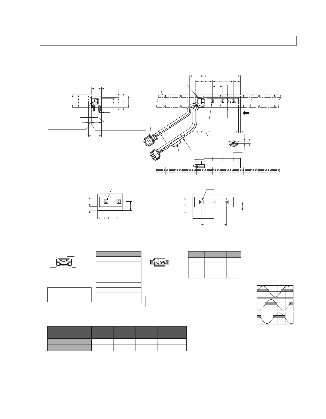
(1) SGLFW-20
Moving Coil: SGLFW-20A
3
(
:
10.2
With Magnet Cover
(
:
10
Without Magnet Cover
)
)
22
)(
44
(
22
(
(6)
)
)
45±0.1
¡¡¡A¡
(32)
2
)
(
0.5
(
:
4.2
34
With Magnet Cover
(
4
: Without Magnet Cover
(
0.8
Gap
(
1
Gap
5
.
5
20
22
5
.
12
:
With Magnet Cover
:
Without Magnet Cover
(With a connector by Tyco Electronics AMP K.K.)
50
Min.
(
4
.
2
Dia.
Hall Sensor
±
500
500
)
50
50
±
(
6
.
1
Nameplate
Dia.
30
)
See the figures
and 2 below.
Min.
12
5
.
17
Magnetic Way
40
5
.
22
)
2
-Screws
)
4-40
#
)
UNC
)
36
)
(
)
10
(
1
L
23030
L
)
12
(
)
(
3
L
(25)
5
.
7
20
AA
5
.
12
1
A−A
The moving coil moves in the direction
indicated by the arrow when current flows
in the order of phase U, V, and W.
7
5
.
8
2
5
.
5
①
SGLFW-20A
20
5
.
12
Hall Sensor
Connector Specifications
9
5
Pin Connector :
17JE-13090-02 (D8C)
by DDK Ltd.
The Mating Connector
Socket Connector:
17JE-13090-02 (D8C)
Stud: 17L-002C or
17L-002C1
6
1
Moving Coil Model
SGLFW-
20A090A¡ 91
20A120A¡ 127 72
¡
090
A
2-M4
Tapped Holes, Depth 5.
5
.
22
30 36
Pin No. Signal
1
+5V (Power supply)
2 Phase U
3 Phase V
4 Phase W
0V (Power supply)
5
6 Not used
7 Not used
8 Not used
9 Not used
L1 L2 L3
36 72 0.7
108 0.9
②
SGLFW-20A
5
20
5
.
30
12
Linear Servomotor
Connector Specifications
Plug:350779-1
Pin :350218-3 or
350547-3(No.1 to 3)
350654-1
350669-1(No.4)
by Tyco Electronics AMP K.K.
The Mating Connector
Cap : 350780-1
Socket: 350536-3 or
350550-3
Note: Models compatible with connectors by
Interconnectron GmbH are also available.
Pin No. Signal
1 Phase U Red
2 Phase V White
3 Phase W Black
4 FG Green
Approx. Mass
kg
¡
120
A
3-M4
Tapped Holes, Depth 5.
5
.
22
5
36
72
Hall Sensor Output Signals
Wire
Color
When the moving coil moves in the
direction indicated by the arrow in the
figure, the relationship between the hall
sensor output signals Su, Sv, Sw and the
inverse power of each motor phase Vu,
Vv, Vw becomes as shown in the figure
below.
Vu
Su
Inverse
Power
Vv
(V)
Vw
Sv
Sw
0 180 360 540
Electrical Angle
)
(
°
143
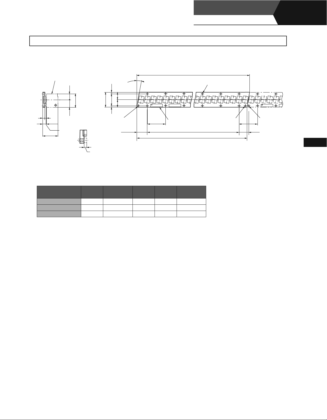
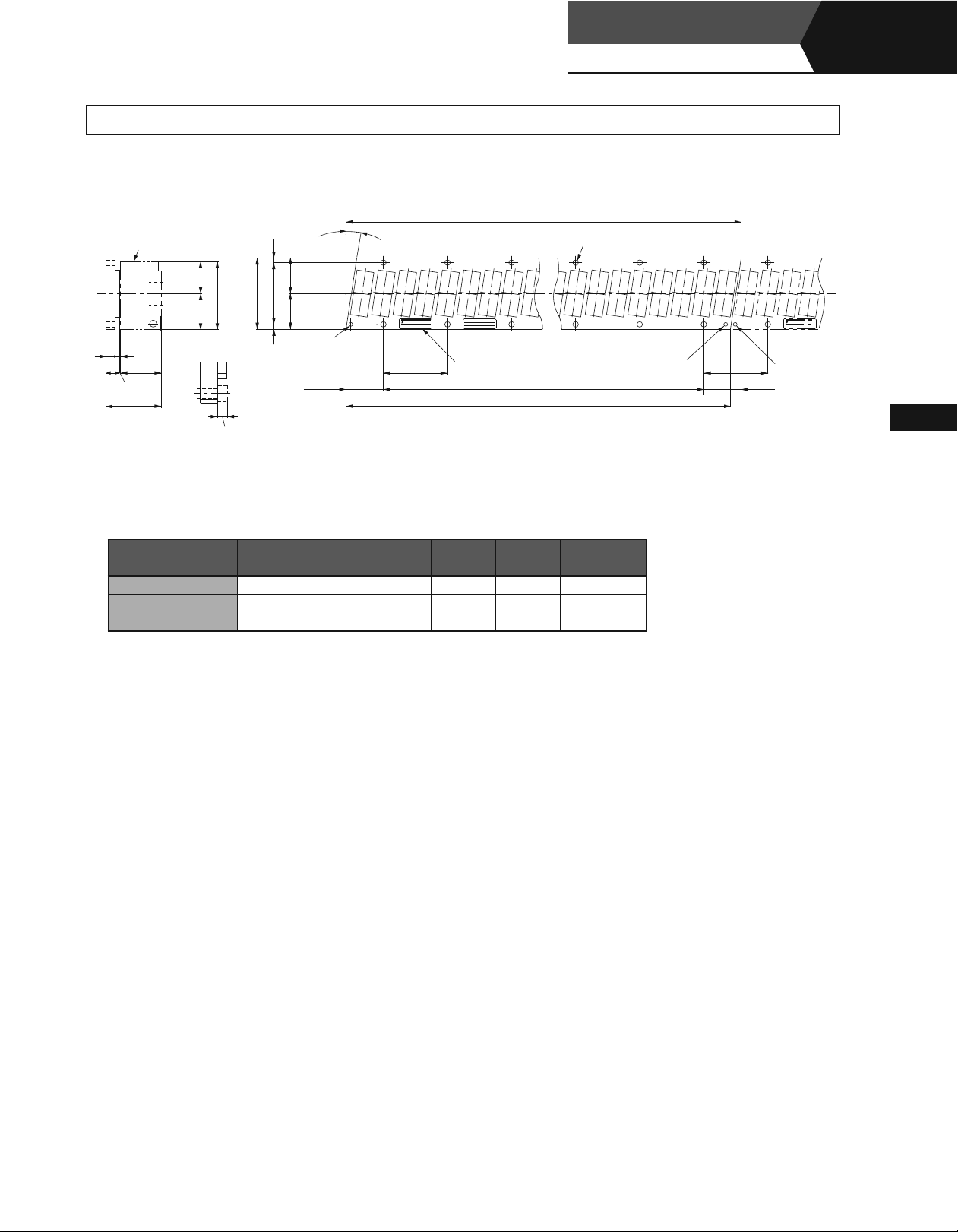
External Dimensions Units: mm
Linear Servomotors
SGLFW
(With F-type iron core)
Linear
Magnetic Way: SGLFM-20
3
Moving Coil
)
5
.
17
)
40
(
)(
5
.
22
(
Gap
(
)
1
6
4
(34)
10
45±0.1
(
Two
A
¡¡¡
)
5
.
4
(
)
22
(
44
22
535
.
4
4
dia. marks are engraved.
Reference Mark
8
30
.
The Height of Screw Head:
(
)
3
L
°
9
9
.
SNSN
YASKAWA
TYPE:
)
0
2
-0.
4.2
Max.
O/N
S/N
MADE IN JAPAN
Nameplate
54
L
1
L
2
1
-0.
3
-0.
2
× N-4.8 Dia.
Mounting Holes
Reference Mark
(
54
(
30.8
SNSN
)
YASKAWA
YASKAWA
TYPE:
(
Reference Mark
)
Assembly Dimensions
Notes: 1 Multiple SGLFM-20¡¡¡A magnetic ways can be connected. Connect magnetic ways so that the reference marks match one on the other in the same direction as shown
in the figure.
2 If you have a pacemaker or any other electronic medical device, do not go near the magnetic way of the linear servomotor.
Magnetic Way Model
SGLFM-
20324A 324
20540A 540
20756A 756
-0.1
L1
-0.3
L2 (L3) N
270 (54
486 (54
702 (54
×
×
×
(331.6) 6 0.9
5)
(547.6) 10 1.4
9)
(763.6) 14 2
13)
Approx. Mass
kg
O/N
S/N
MADE
)
Linear Servomotors
144
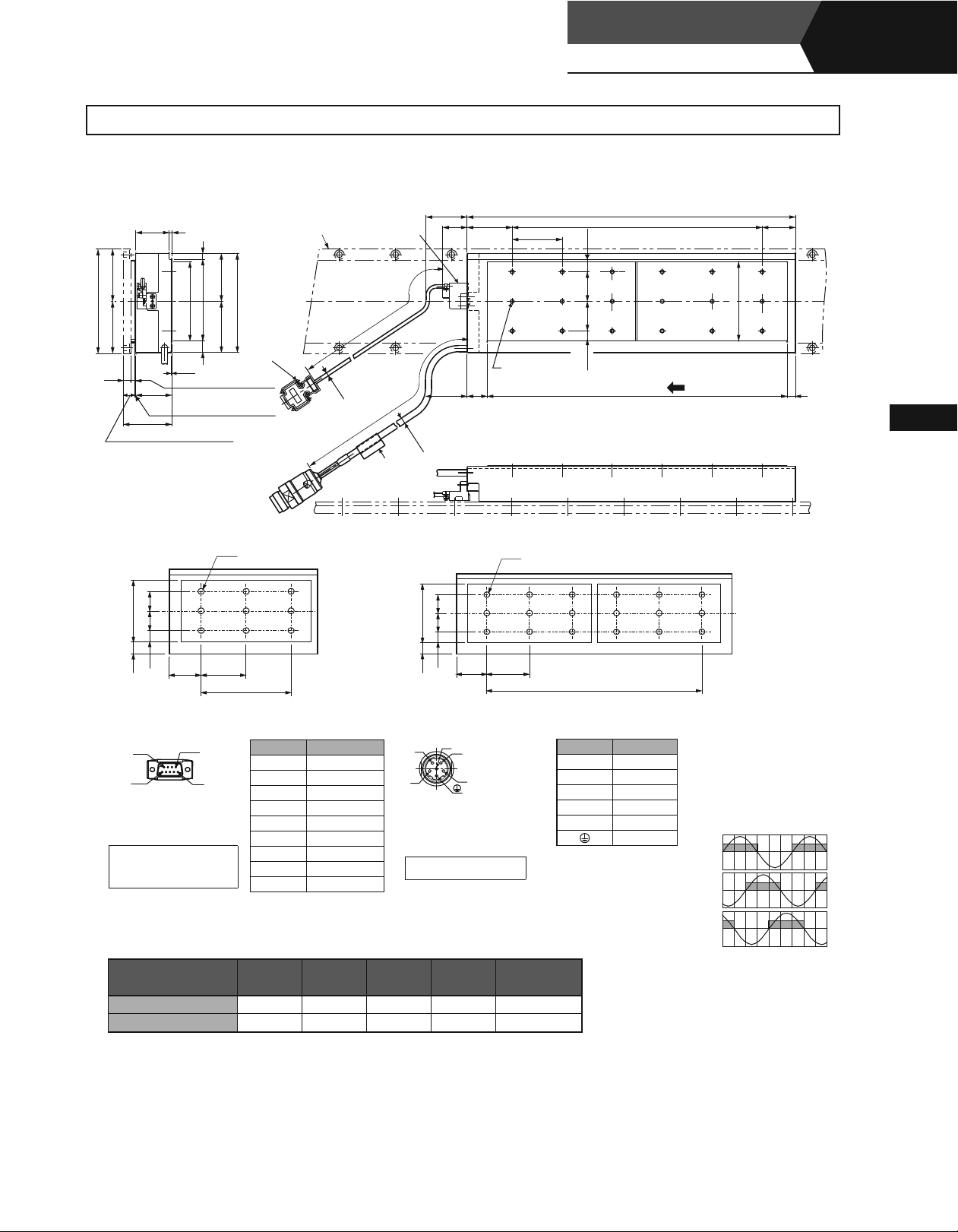
External Dimensions Units: mm
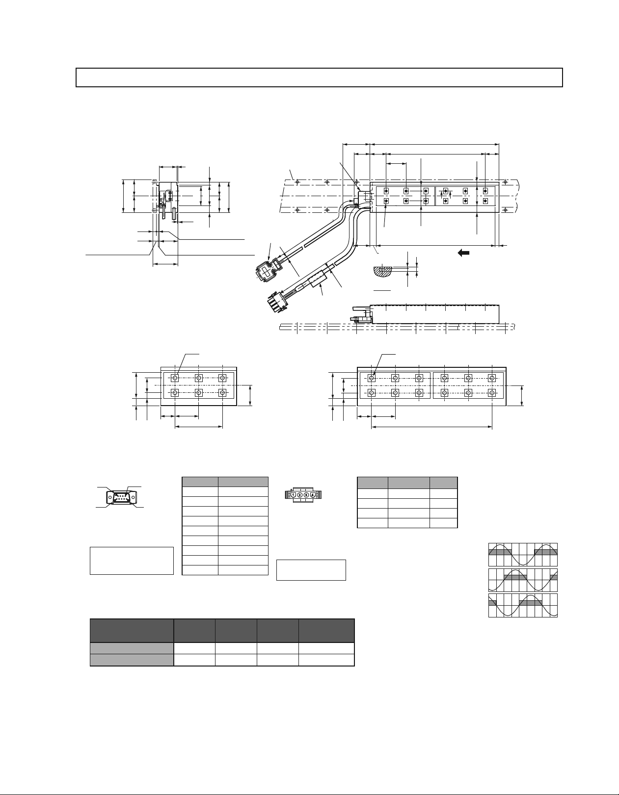
(2) SGLFW-35
Moving Coil: SGLFW-35
3
)
60
(
(
10.2
: With Magnet Cover
(
10
: Without Magnet Cover
)
30
(
)
30
(
(6)
)
)
(32)
34
±
0.1
45
¡¡¡¡A¡
2
5
.
5
25
)
37
35
(
30
5
.
0.5
12
(
4.2
: With Magnet Cover
(
4
: Without Magnet Cover
(
0.8
Gap
: With Magnet Cover
(
:
1
Without Magnet Cover
Gap
(With a connector by Tyco Electronics AMP K.K.)
50
Min.
30
30
Hall Sensor
Magnetic Way
55
2
-Screws
)
4-40
UNC
#
)
)
)
50
±
500
30
(
4
.
2
Dia.
50
±
500
)
Min.
(
6
.
1
Dia.
)
Nameplate
36
See the figures① and ② below.
12
A−A
1
L
2
L
)
5
.
10
(
A
18
)
5
.
8
(
5
.
8
2
A
3
L
The moving coil moves in the direction
(25)
)
5
.
7
(
35
)
5
.
12
(
indicated by the arrow when current flows
in the order of phase U, V, and W.
5
.
5
7
①
SGLFW-
35
35¡120
18
¡
A
6-M4
Tapped Holes, Depth 5.
30
5
5
.
.
30 36
8
12
Hall Sensor
Connector Specifications
9
5
Pin Connector
17JE-23090-02 (D8C)
by DDK Ltd.
The Mating Connector
Socket Connector:
17JE-13090-02(D8C)
Stud:17L-002C or
17L-002C1
6
1
Moving Coil Model
SGLFW-
72
Pin No. Signal
1
+5V (Power supply)
2 Phase U
3 Phase V
4 Phase W
0V (Power supply)
5
6 Not used
7 Not used
8 Not used
9 Not used
L1 L2 L3
Linear Servomotor
Connector Specifications
Plug: 350779-1
Pin : 350218-3 or
350547-3 (No.1 to 3)
350654-1
350669-1 (No.4)
by Tyco Electronics AMP K.K.
The Mating Connector
35¡120A¡ 127 72 108 1.3
230A¡ 235 180 216 2.3
35¡
5
Cap : 350780-1
Socket: 350536-3 or
350550-3
Approx. Mass
②
kg
SGLFW-
35
188
5
5
.
.
12
35¡230
30
Pin No. Signal
¡
A
12-M4
Tapped Holes, Depth 5.
36
1 Phase U Red
2 Phase V White
3 Phase W Black
4 FG Green
180
(
36
Wire
Color
5
)
5
×
Hall Sensor Output Signals
When the moving coil moves in the
direction indicated by the arrow in the
figure, the relationship between the hall
sensor output signals Su, Sv, Sw and the
inverse power of each motor phase Vu,
Vv, Vw becomes as shown in the figure
below.
Vu
Su
Inverse
Power
Vv
(V)
Vw
0 180 360 540
30
Sv
Sw
Electrical Angle
)
(
°
145
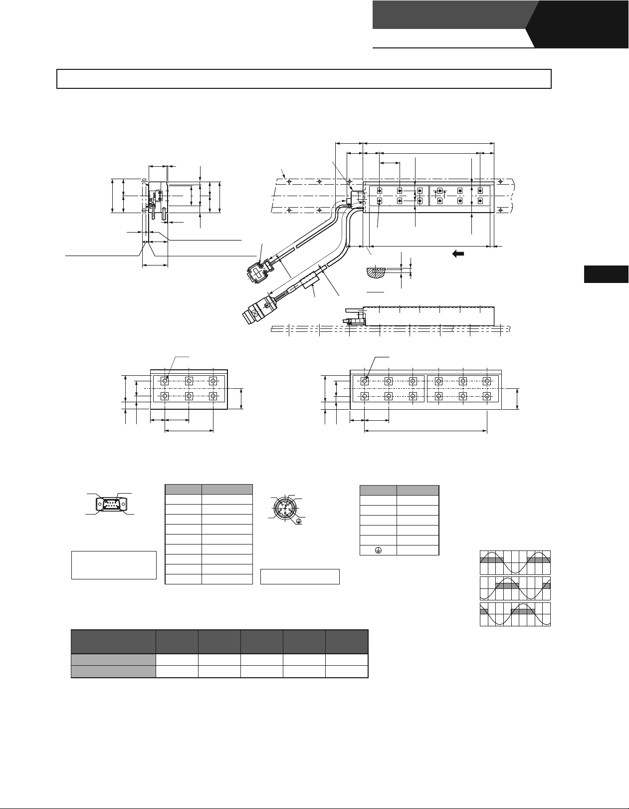
External Dimensions Units: mm
Linear Servomotors
SGLFW
(With F-type iron core)
Linear
Moving Coil: SGLFW-35
3
)
30
)
(
60
)
(
30
(
(6)
(
:
10.2
With Magnet Cover
(
:
10
Without Magnet Cover
①
SGLFW-
35
5
.
12
)
18
5
.
8
)
45
(32)
±
35¡120
¡¡¡¡A¡
2
)
35
(
0.5
(
:
4.2
With Magnet Cover
34
(
:
4
Without Magnet Cover
(
0.8
Gap
0.1
(
:
1
Gap
A¡D
30 36
72
D (With a connector by Interconnectron GmbH)
(
4
5
.
2
Dia.
500
Hall Sensor
50
±
500
)
50
±
(
6
.
1
Dia.
Nameplate
②
SGLFW-
35
5
.
12
188
5
.
5
.
5
25
37
55
30
5
.
12
:
With Magnet Cover
)
)
Without Magnet Cover
6-M4
Tapped Holes, Depth 5.
30
2
-Screws
4-40
#
)
)
Magnetic Way
UNC
50
)
Min.
30
30
Min.
35¡230
30 36
30
36
See the figures
and ② below.
12
A−A
A¡D
12-M4
1
L
2
L
)
5
.
10
(
AA
18
)
5
.
8
(
①
3
L
5
.
8
2
The moving coil moves in the direction
25
)
5
.
7
(
35
)
5
.
12
(
7
indicated by the arrow when current flows
in the order of phase U, V, and W.
5
.
5
Tapped Holes, Depth 5.
(
)
36
5
180
×
5
Linear Servomotors
30
Hall Sensor
Connector Specifications
9
6
5
Pin Connector :
17JE-23090-02 (D8C)
by DDK Ltd.
The Mating Connector
Socket Connector:
17JE-13090-02 (D8C)
Stud: 17L-002C or
17L-002C1
Moving Coil Model
SGLFW-
Pin No. Signal
1
+5V (Power supply)
1
2 Phase U
3 Phase V
4 Phase W
0V (Power supply)
5
6 Not used
7 Not used
8 Not used
9 Not used
L1 L2 L3 N
Linear Servomotor
Connector Specifications
6
5
1
4
Extension: ARRA06AMRPN182
Pin : 021.279.1020
by Interconnectron GmbH
The Mating Connector
Plug : APRA06BFRDN170
Socket: 020.105.1020
2
35¡120A¡D 127 72 108 6 1.3
35¡230A¡D 235 180 216 12 2.3
Approx. Mass
kg
Pin No. Name
1 Phase U
2 Phase V
4 Phase W
5 Not used
6 Not used
Ground
Hall Sensor Output Signals
When the moving coil moves in the
direction indicated by the arrow in the
figure, the relationship between the hall
sensor output signals Su, Sv, Sw and the
inverse power of each motor phase Vu,
Vv, Vw becomes as shown in the figure
below.
Vu
Su
Inverse
Vv
Power
(V)
Vw
Sv
Sw
0 180 360 540
Electrical Angle
)
(
°
146

External Dimensions Units: mm
Magnetic Way: SGLFM-35
3
Moving Coil
)
25
(
)
55
)
(
30
(
6104
)
(
34
±
0.1
45
(
Gap
(
Two
)
1
The Height of Screw Head:
60
4
dia. marks are engraved.
A
¡¡¡
)
5
.
4
(
)
30
(
51
30
5
.
4
Reference Mark
32.2
4.2
9
9
.
0
-0.
Max.
)
(
3
L
°
2
× N-4.8 Dia. Mounting Holes
SSNSSNNN
YASKAW A
TYPE:
)
2
54
O/N
S/N
DATE
MADE IN JAPAN
Nameplate
Reference Mark
2
L
1
-0.
1
L
3
-0.
(
Reference Mark
(54)
)
(
32.2
TYPE:
YASKAWA
Assembly Dimensions
Notes: 1 Multiple SGLFM-35¡¡¡A magnetic ways can be connected. Connect magnetic ways so that the reference marks match one on the other in the same direction as shown
in the figure.
2 If you have a pacemaker or any other electronic medical device, do not go near the magnetic way of the linear servomotor.
Magnetic Way Model
SGLFM-
35324A 324
35540A 540
35756A 756
-0.1
L1
-0.3
L2 (L3) N
270 (54
486 (54
702 (54
×
×
×
(334.4) 6 1.2
5)
(550.4) 10 2
9)
(766.4) 14 2.9
13)
Approx. Mass
kg
O/N
S/N
MADE
)
147

External Dimensions Units: mm
(3) SGLFW-50
Moving Coil: SGLFW-50
3
(40)
)
5
.
)
37
(
)
75
(
5
.
37
(
(9)
(
)
5.2
43±0.05
58±0.1
(
14.2
: With Magnet Cover
(
14
: Without Magnet Cover
3
)
)
48
(
(
0.5
(
:
With Magnet Cover
5.2
(
:
Without Magnet Cover
5
(
:
0.8
Gap
(
:
Without Magnet Cover
1
Gap
)
¡¡¡¡B¡
7
75
.
5
.
33
71
5
.
75
.
64
37
2
#4-40UNC
)
)
With Magnet Cover
)
)
Screws
-
)
Magnetic Way
Linear Servomotors
SGLFW
(With a connector by Tyco Electronics AMP K.K.)
Min.
50
55
(
4
.
2
Dia.
500
)
500
50
±
50
±
Hall Sensor
Nameplate
30
Min.
25
50
(
7
.
4
Dia.
)
60
)
15
(
5
.
23
)
12
(
See the figures
and ② below.
①
(With F-type iron core)
1
L
2
L
The moving coil moves in the direction
indicated by the arrow when current flows
in the order of phase U, V, and W.
3
L
(40)
Linear
10
①
SGLFW-
5
.
48
23
12
14
Hall Sensor
Connector Specifications
9
5
Pin Connector :
17JE-23090-02 (D8C)
by DDK Ltd.
The Mating Connector
Socket Connector:
17JE-13090-02 (D8C)
Stud: 17L-002C or
17L-002C1
6
1
Moving Coil Model
SGLFW-
50¡200B¡ 215
50¡
380B¡ 395 300 360 6.9
50□200
55 60
□
B
6-M5
Tapped Holes, Depth 9.
120
Pin No. Signal
1
+5V (Power supply)
2 Phase U
3 Phase V
4 Phase W
0V (Power supply)
5
6 Not used
7 Not used
8 Not used
9 Not used
L1 L2 L3
120 180 3.5
②
SGLFW-
5
5
.
48
23
12
14
Linear Servomotor
Connector Specifications
Plug:350779-1
Pin :350218-3 or
350547-3(No.1 to 3)
350654-1
350669-1(No.4)
by Tyco Electronics AMP K.K.
The Mating Connector
Cap : 350780-1
Socket: 350536-3 or
350550-3
Approx. Mass
kg
50□380
55 60
□
B
12-M5
Tapped Holes, Depth 9.
(
60
300
Pin No. Signal
1 Phase U Red
2 Phase V White
3 Phase W Black
4 FG Green
×
Color
Wire
5
)
5
Hall Sensor Output Signals
When the moving coil moves in the
direction indicated by the arrow in the
figure, the relationship between the hall
sensor output signals Su, Sv, Sw and the
inverse power of each motor phase Vu,
Vv, Vw becomes as shown in the figure
below.
Vu
Su
Inverse
Power
Vv
(V)
Vw
0 180 360 540
Electrical Angle
Linear Servomotors
Sv
Sw
)
(
°
148

External Dimensions Units: mm
Moving Coil: SGLFW-50
3
(40)
3
)
5
.
)
37
(
)
75
(
5
.
37
(
(9)
58
(
:
14.2
With Magnet Cover
(
:
14
Without Magnet Cover
)
48
(
5
0
.
(
:
5.2
43
(
:
5
Without Magnet Cover
±
0.1
(
:
0.8
Gap
(
:
1
Gap
Without Magnet Cover
①
SGLFW-
5
.
48
23
5
.
50
With Magnet Cover
With Magnet Cover
)
)
7
14
7537
.
5
.
33
71
75
.
50¡200
¡¡¡¡B¡
Magnetic Way
2
-Screws
4-40
UNC
#
)
)
)
)
B¡D
6-M5
Tapped Holes, Depth 9.
D (With a connector by Interconnectron GmbH)
50
Min.
55
Dia.
30
60
See the figures
50
Min.
and ② below.
25
①
)
②
SGLFW-
50¡380
B¡D
5
5
.
48
23
(
4
.
500
2
Dia.
Hall Sensor
50
±
±
500
)
Nameplate
50
(
7
.
4
1
L
2
L
)
15
(
5
.
23
)
12
(
3
L
12-M5
Tapped Holes, Depth 9.
40
48
The moving coil moves in the direction
indicated by the arrow when current flows
in the order of phase U, V, and W.
10
5
12
14
55
60
120
Hall Sensor
Connector Specifications
9
5
Pin Connector :
17JE-23090-02 (D8C)
by DDK Ltd.
The Mating Connector
Socket Connector:
17JE-13090-02 (D8C)
Stud: 17L-002C or
17L-002C1
6
1
Moving Coil Model
SGLFW-
50¡200B¡D
Pin No. Signal
1
+5V (Power supply)
2 Phase U
3 Phase V
4 Phase W
0V (Power supply)
5
6 Not used
7 Not used
8 Not used
9 Not used
L1 L2 L3 N
215 120 180
Linear Servomotor
Connector Specifications
Extension: ARRA06AMRPN182
Pin : 021.279.1020
by Interconnectron GmbH
The Mating Connector
Plug : APRA06BFRDN170
Socket: 020.105.1020
6
5
1
4
2
6 3.5
50¡380B¡D 395 300 360 12 6.9
12
14
55 60
Approx. Mass
kg
300
Pin No. Name
1 Phase U
2 Phase V
4 Phase W
5 Not used
6 Not used
Ground
(
)
60
5
×
Hall Sensor Output Signals
When the moving coil moves in the
direction indicated by the arrow in the
figure, the relationship between the hall
sensor output signals Su, Sv, Sw and the
inverse power of each motor phase Vu,
Vv, Vw becomes as shown in the figure
below.
Vu
Su
Inverse
Power
Vv
(V)
Vw
Sv
Sw
0 180 360 540
Electrical Angle
)
(
°
149
External Dimensions Units: mm
Linear Servomotors
SGLFW
(With F-type iron core)
Linear
Magnetic Way: SGLFM-50
3
Moving Coil
)
75
.
)
33
5
(
.
)
71
(
75
.
37
(
95
(43)
14
(
Gap
±
0.1
58
(
4
Two
)
1
75
dia. marks are engraved.
The Height of Screw Head:
A
¡¡¡
)
5
(
)
5
.
37
(
65
5
.
37
5
Reference Mark
39.4
8.6
(
)
3
L
˚
2
× N-5.8 Dia. Mounting Holes
SSSNSNNN
YASKAWA
TYPE:
)
0
2
-0.
5.2
67.5
Max.
O/N
S/N
MADE IN JAPAN
DATE
Nameplate
Reference Mark
2
L
1
-0.
1
L
3
-0.
(
67.5
)
(
Reference Mark
(
)
39.4
YASKAWA
TYPE:
Assembly Dimensions
Notes: 1 Multiple SGLFM-50¡¡¡A magnetic ways can be connected. Connect magnetic ways so that the reference marks match one on the other in the same direction as shown
in the figure.
2 If you have a pacemaker or any other electronic medical device, do not go near the magnetic way of the linear servomotor.
Magnetic Way Model
SGLFM-
50405A 405
50675A 675
50945A 945
-0.1
L1
-0.3
L2 (L3) N
337.5 (67.5
607.5 (67.5
877.5 (67.5
×
5)
×
9)
×
13)
(416.3) 6 2.8
(686.3) 10 4.6
(956.3) 14 6.5
Approx. Mass
kg
)
Linear Servomotors
150

External Dimensions Units: mm
(4) SGLFW-1Z
Moving Coil: SGLFW-1Z
3
(40)
)
5
.
62
)
125
(
) (
5
.
62
(
(9)
43
±
0.158
(
:
14.2
With Magnet Cover
(
:
14
Without Magnet Cover
3
7
96
98
14
0.5
(
:
5.2
With Magnet Cover
(
:
5
Without Magnet Cover
(
:
0.8
Gap
With Magnet Cover
(
:
1
Gap
Without Magnet Cover
561
.
57
5
.
)
)
¡¡¡¡B¡
119
2
-Screws
4-40
#
UNC
)
)
)
Magnetic Way
)
(With a connector by Tyco Electronics AMP K.K.)
50
Min.
(
4
.
2
Dia.
Hall Sensor
50
±
500
)
50500
±
Nameplate
(
8
.
4
Dia.
5530
25
50
Min.
60
See the figures
and ② below.
)
)
15
(
535
.
35
5
.
)
12
(
①
1
L
2
L
40
96
The moving coil moves in the direction
indicated by the arrow when current flows
in the order of phase U, V, and W.
3
L
10
①
SGLFW-1Z
5
.
35
96
5
.
35
12
14
Hall Sensor
Connector Specifications
9
5
Pin Connector :
17JE-23090-02 (D8C)
by DDK Ltd.
The Mating Connector
Socket Connector:
17JE-13090-02 (D8C)
Stud: 17L-002C or
17L-002C1
□
55
6
1
Moving Coil Model
SGLFW-
1Z¡200B¡ 215
1Z
¡380B¡ 395 300 360 18 11.5
200
□
B
9-M5
Tapped Holes, Depth 9.
60
120
Pin No. Signal
L1 L2 L3 N
1
+5V (Power supply)
2 Phase U
3 Phase V
4 Phase W
0V (Power supply)
5
6 Not used
7 Not used
8 Not used
9 Not used
120 180 9 6.4
②
SGLFW-1Z
5
535
.
35
96
5
.
12
14
Linear Servomotor
Connector Specifications
Plug:350779-1
Pin :350218-3 or
350547-3(No.1 to 3)
350654-1
350669-1(No.4)
by Tyco Electronics AMP K.K.
The Mating Connector
Cap : 350780-1
Socket: 350536-3 or
350550-3
55
□
380
B
60
Approx. Mass
□
18-M5
Tapped Holes, Depth 9.
(
300
60×5
Pin No. Signal
1 Phase U Red
2 Phase V White
3 Phase W Black
4 FG Green
kg
5
)
Hall Sensor Output Signals
Wire
Color
When the moving coil moves in the
direction indicated by the arrow in the
figure, the relationship between the hall
sensor output signals Su, Sv, Sw and the
inverse power of each motor phase Vu,
Vv, Vw becomes as shown in the figure
below.
Vu
Su
Inverse
Power
Vv
(V)
Vw
Sv
Sw
0 180 360 540
Electrical Angle
)
(
°
151
External Dimensions Units: mm
Linear Servomotors
SGLFW
(With F-type iron core)
Linear
Moving Coil: SGLFW-1Z
3
(40)
3
7
)
5
.
62
)
125
(
) (
5
.
62
(
(9)
58
(
:
14.2
With Magnet Cover
(
:
14
Without Magnet Cover
①
SGLFW-1Z
96
96
0.5
(
:
5.2
With Magnet Cover
43
(
:
5
Without Magnet Cover
(
Gap
±
0.1
(
Gap
□
535
.
35
5
.
98
14
0.8
:
1
Without Magnet Cover
200
¡¡¡¡B¡
561
.
57
119
5
.
2
#
:
With Magnet Cover
)
)
B□D
9-M5
D (With a connector by Interconnectron GmbH)
Magnetic Way
-Screws
4-40
UNC
)
)
)
)
Tapped Holes, Depth 9.
500
(
4
.
2
Dia.
)
Hall Sensor
50
±
50
±
500
Nameplate
5
50
50
(
8
.
4
Dia.
)
②
SGLFW-1ZD
535
.
35
96
5
.
Min.
30
Min.
55
25
380
60
See the figures
and ② below.
B□D
18-M5
Tapped Holes, Depth 9.
1
L
2
)
15
(
535
.
35
5
.
)
12
(
①
L
The moving coil moves in the direction
indicated by the arrow when current flows
in the order of phase U, V, and W.
3
L
5
40
96
10
Linear Servomotors
12
14
60
55
12
14
55
120
Hall Sensor
Connector Specifications
9
5
Pin Connector :
17JE-23090-02 (D8C)
by DDK Ltd.
The Mating Connector
Socket Connector:
17JE-13090-02 (D8C)
Stud: 17L-002C or
17L-002C1
6
1
Moving Coil Model
SGLFW-
1Z¡200B¡D
Pin No. Signal
1
+5V (Power supply)
2 Phase U
3 Phase V
4 Phase W
0V (Power supply)
5
6 Not used
7 Not used
8 Not used
9 Not used
L1 L2 L3 N
215 120 180
Linear Servomotor
Connector Specifications
6
5
1
4
Extension: ARRA06AMRPN182
Pin : 021.279.1020
by Interconnectron GmbH
The Mating Connector
Plug : APRA06BFRDN170
Socket: 020.105.1020
2
9 6.4
1ZD380B¡D 395 300 360 18 11.5
60
Approx. Mass
kg
(
)
300
60×5
Pin No. Name
1 Phase U
2 Phase V
4 Phase W
5 Not used
6 Not used
Ground
Hall Sensor Output Signals
When the moving coil moves in the
direction indicated by the arrow in the
figure, the relationship between the hall
sensor output signals Su, Sv, Sw and the
inverse power of each motor phase Vu,
Vv, Vw becomes as shown in the figure
below.
Vu
Su
Inverse
Power
Vv
(V)
Vw
Sv
Sw
0 180 360 540
Electrical Angle
)
(
°
152

External Dimensions Units: mm
Magnetic Way: SGLFM-1Z
3
Moving Coil
)
5
.
57
)(
5
.
61
(
9
5
(43)
14
(
)
1
Gap
±
58
0.1
1.5
The Height of Screw Head:
)
119
(
Reference Mark
(
4
Two
5
.
11
A
¡¡¡
°
6
.
8
)
5
.
62
(
5
.
62
0
43.2
2
-0.
125
)
5
.
6
(
112
5
.
6
dia. marks are engraved.
6.7
Max.
(
)
3
L
×
2
N-7 Dia.Mounting Holes
11.5
Dia. counter boring, Depth 1.
5
SSSSNNNN
YASKAWA
TYPE:
67.5
O/N
S/N
MADE IN JAPAN
DATE
Nameplate
Reference Mark
2
L
1
-0.
1
L
3
-0.
(
67.5
)
YASKAWA
TYPE:
(
Reference Mark
)
(
)
43.2
Assembly Dimensions
Notes: 1 Multiple SGLFM-1Z¡¡¡A magnetic ways can be connected. Connect magnetic ways so that the reference marks match one on the other in the same direction as
shown in the figure.
2 If you have a pacemaker or any other electronic medical device, do not go near the magnetic way of the linear servomotor.
)
Magnetic Way Model
SGLFM-
-0.1
L1
-0.3
L2 L3 N
1Z405A 405 337.5 (67.5 × 5) (423.9) 6 5
1Z675A
675 607.5 (67.5 × 9) (693.9)
10 8.3
1Z945A 945 877.5 (67.5 × 13) (963.9) 14 12
Approx. Mass
kg
153
 Loading...