

Page 1
AC Servo Drives
Σ-V Series
/
Σ-V Series for
Large-Capacity Models
USER'S MANUAL
Safety Module
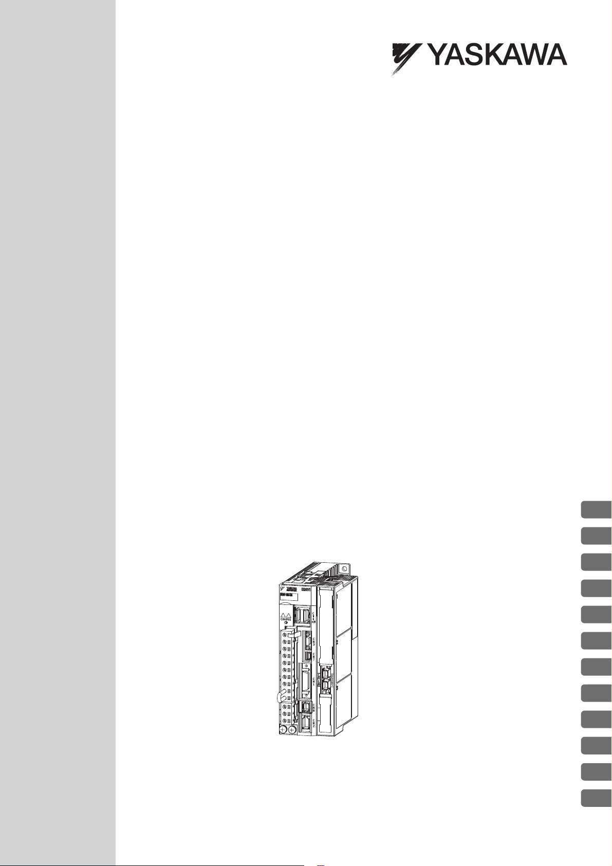
Model: SGDV-OSA01A
Checking Products
Specifications
SERVOPACK Installation
Wiring and Connection
Precautions and Basic Settings
Required before Starting Operation
Safety Functions
Setting Parameters
Utility Functions
Monitor Mode
Active Mode Function
Troubleshooting
Appendix
1
2
3
4
5
6
7
8
9
10
11
12
MANUAL NO. SIEP C720829 06C
Page 2

Copyright © 2010 YASKAWA ELECTRIC CORPORATION
All rights reserved. No part of this publication may be reproduced, stored in a retrieval system,
or transmitted, in any form, or by any means, mechanical, electronic, photocopying, recording,
or otherwise, without the prior written permission of Yaskawa. No patent liability is assumed
with respect to the use of the information contained herein. Moreover, because Yaskawa is constantly striving to improve its high-quality products, the information contained in this manual is
subject to change without notice. Every precaution has been taken in the preparation of this
manual. Nevertheless, Yaskawa assumes no responsibility for errors or omissions. Neither is
any liability assumed for damages resulting from the use of the information contained in this
publication.
Page 3
About this Manual
This manual describes informations required for designing, and maintaining the Safety Module for Σ-V series
and Large-Capacity Σ-V Series SERVOPACKs.
Be sure to refer to this manual and perform design and maintenance to select devices correctly.
Keep this manual in a location where it can be accessed for reference whenever required.
IMPORTANT Explanations
The following icon is displayed for explanations requiring special attention.
Notation Used in this Manual
• Reverse Symbol Notation
In this manual, the names of reverse signals (ones that are valid when low) are written with a forward slash (/)
before the signal name, as shown in the following example:
• Indicates important information that should be memorized, as well as precautions, such as
alarm displays, that do not involve potential damage to equipment.
Example
The notation for
• Parameter Notation
The following two types of notations are used for parameter digit places and settings.
Example
Pn000㧩㨚㧜㧜㧜㧜
BK is /BK.
Notation Example for Pn000
Notation Method
Digit 1
Digit 2
Digit 3
Digit 4
Pn000.0
Pn000.1
Pn000.2
Pn000.3
Digit Notation
Meaning
Indicates digit 1
of the parameter (Pn000).
Indicates digit 2
of the parameter (Pn000).
Indicates digit 3
of the parameter (Pn000).
Indicates digit 4
of the parameter (Pn000).
Set Value Notation
Notation Method Meaning
Pn000.0 = x
or n.x
Pn000.1 = x
or n.x
Pn000.2 = x
or n.x
Pn000.3 = x
or n.x
Indicates that digit 1 of the
parameter (Pn000) is x.
Indicates that digit 2 of the
parameter (Pn000) is x.
Indicates that digit 3 of the
parameter (Pn000) is x.
Indicates that digit 4 of the
parameter (Pn000) is x.
iii
Page 4

Manuals Related to the Σ-V Series and Large-Capacity Σ-V Series
Refer to the following manuals as required.
Name
Σ-V Series Product
Catalog
(KAEP S800000 42)
Large-Capacity Σ-V
Series
(KAEPS 800000 86)
Σ-V Series/Σ-V Series for
Large-Capacity Models
Installation Guide
Safety Option Module
(TOBP C720829 06)
Σ-V Series User's Manual
Setup Rotational Motor
(SIEP S800000 43)
Σ-V Series User's Manual
Setup Linear Motor
(SIEP S800000 44)
Σ-V Series User’s Manual
Design and Maintenance
Rotational Motor
Analog Voltage and Pulse
Train Reference
(SIEP S800000 45)
Σ-V Series User’s Manual
Design and Maintenance
Linear Motor
Analog Voltage and
Pulse Train Reference
(SIEP S800000 47)
Σ-V Series User’s Manual
Design and Maintenance
Rotational Motor
MECHATROLINK-II
Communications
Reference
(SIEP S800000 46)
Σ-V Series User’s Manual
Design and Maintenance
Linear Motor
MECHATROLINK-II
Communications
Reference
(SIEP S800000 48)
Σ-V Series/DC Power
Input Σ-V Series/Σ-V
Series for Large-Capacity
Models User’s Manual
MECHATROLINK-II
Command
(SIEP S800000 54)
Σ-V Series User’s Manual
Design and Maintenance
Rotational Motor
MECHATROLINK-III
Communications
Reference
(SIEP S800000 64)
Selecting
Models and
Peripheral
Devices
999
Ratings and
Specifications
System
Design
999
99 999
99 999
99 999
99 999
999
99 999
Panels and
Wiring
Trial
Operation
9
99
99
Trial
Operation
and Servo
Adjustment
Maintenance and
Inspection
iv
Page 5

(cont’d)
Name
Σ-V Series User’s Manual
Design and Maintenance
Linear Motor
MECHATROLINK-III
Communications
Reference
(SIEP S800000 65)
Σ-V Series/DC Power
Input Σ-V Series/Σ-V
Series for Large-Capacity
Models User’s Manual
MECHATROLINK-III
Standard Servo Profile
Commands
(SIEP S800000 63)
Σ-V Series User’s Manual
Design and Maintenance
Rotational Motor
Command Option
Attachable Type
(SIEP S800000 60)
Σ-V Series User’s Manual
Design and Maintenance
Linear Motor
Command Option
Attachable Type
(SIEP S800000 66)
Σ-V Series User's Manual
For Use with LargeCapacity Models
Setup Rotational Motor
(SIEP S800000 89)
Σ-V Series User’s Manual
For Use with LargeCapacity Models
Design and Maintenance
Rotational Motor
Analog Voltage and
Pulse Train Reference
(SIEP S800000 88)
Σ-V Series User’s Manual
For Use with LargeCapacity Models
Design and Maintenance
Rotational Motor
MECHATROLINK-II
Communications
Reference
(SIEP S800000 90)
Σ-V Series User’s Manual
For Use with LargeCapacity Models
Design and Maintenance
Rotational Motor
MECHATROLINK-III
Communications
Reference
(SIEP S800000 93)
Selecting
Models and
Peripheral
Devices
Ratings and
Specifications
99 999
99 999
99 999
System
Design
999
Panels and
Wiring
Trial
Operation
Trial
Operation
and Servo
Adjustment
Maintenance and
Inspection
99
99 999
99 999
99 999
v
Page 6
WARNING
CAUTION
PROHIBITED
MANDATORY
(cont’d)
Name
Σ-V Series User's Manual
For Use with LargeCapacity Models
Design and Maintenance
Rotational Motor
Command Option
Attachable Type
(SIEP S800000 98)
Σ-V Series User’s Manual
Operation of Digital
Operator
(SIEP S800000 55)
SigmaWin+ Online
Manual Σ-V Component
(SIEP S800000 73)
AC Servomotor
Safety Precautions
(TOBP C230200 00)
Σ-V Series
AC SERVOPACK SGDV
Safety Precautions
(TOBP C710800 10)
Σ-V Series
Safety Precautions
For Use with LargeCapacity Models
(TOBP C710829 07)
Selecting
Models and
Peripheral
Devices
999
999
Ratings and
Specifications
9999
System
Design
Panels and
Wiring
99
Trial
Operation
99
999
Trial
Operation
and Servo
Adjustment
Maintenance and
Inspection
Safety Information
The following conventions are used to indicate precautions in this manual. Failure to heed precautions provided in this manual can result in serious or possibly even fatal injury or damage to the products or to related
equipment and systems.
Indicates precautions that, if not heeded, could possibly result in loss of
life or serious injury.
Indicates precautions that, if not heeded, could result in relatively serious
or minor injury, damage to the product, or faulty operation.
In some situations, the precautions indicated could have serious
consequences if not heeded.
Indicates prohibited actions that must not be performed. For example,
this symbol would be used to indicate that fire is prohibited as follows:
Indicates compulsory actions that must be performed. For example, this
symbol would be used as follows to indicate that grounding is
compulsory:
vi
Page 7
Safety Precautions
These safety precautions are very important. Read them before performing any procedures such as checking
products on delivery, storage and transportation, installation, wiring, operation and inspection, or disposal. Be
sure to always observe these precautions thoroughly.
• Never touch any rotating motor parts while the motor is running.
Failure to observe this warning may result in injury.
• Before starting operation with a machine connected, make sure that an emergency stop can be
applied at any time.
Failure to observe this warning may result in injury or damage to the product.
• Never touch the inside of the SERVOPACKs.
Failure to observe this warning may result in electric shock.
• Do not remove the cover of the power supply terminal block while the power is ON.
Failure to observe this warning may result in electric shock.
• After the power is turned OFF or after a voltage resistance test, do not touch terminals while the
CHARGE lamp is ON.
Residual voltage may cause electric shock.
• Follow the procedures and instructions provided in this manual for trial operation.
Failure to do so may result not only in faulty operation and damage to equipment, but also in personal injury.
• The multi-turn serial data output range for the Σ-V Series and Large-Capacity Σ-V Series absolute
position detecting system is different from that of earlier systems with 15-bit and 12-bit encoders. In
particular, change the system to configure the Σ Series infinite-length positioning system with the Σ-
V Series or Large-Capacity Σ-V Series.
• The multi-turn limit value need not be changed except for special applications.
Changing it inappropriately or unintentionally can be dangerous.
• If the Multi-turn Limit Disagreement alarm occurs, check the setting of parameter Pn205 in the SERVOPACK to be sure that it is correct.
If Fn013 is executed when an incorrect parameter value is set, an incorrect value will be set in the encoder.
The alarm will disappear even if an incorrect value is set, but incorrect positions will be detected, resulting in
a dangerous situation where the machine will move to unexpected positions.
• Do not remove the front cover, cables, connectors, or optional items from the upper front of the
SERVOPACK while the power is ON.
Failure to observe this warning may result in electric shock.
• Do not damage, press, exert excessive force on, or place heavy objects on the cables.
Failure to observe this warning may result in electric shock, stopping operation of the product, or fire.
• Provide an appropriate stopping device on the machine side to ensure safety.
The holding brake on a servomotor with a brake is not a braking device for ensuring safety.
Failure to observe this warning may result in injury.
• Connect the ground terminal according to local electrical codes (100 Ω or less for a SERVOPACK
with a 100 V, 200 V power supply, 10 Ω or less for a SERVOPACK with a 400 V power supply).
Improper grounding may result in electric shock or fire.
WARNING
vii
Page 8

WARNING
• Installation, disassembly, or repair must be performed only by authorized personnel.
Failure to observe this warning may result in electric shock or injury.
• Engineers designing a mechanical system using the safety functions of the Safety Module must
have complete knowledge of the relative safety standards and a full understanding of the safety
functions of the Safety Module.
Improper use may result in injury or damage to the product.
• When creating a safety design for a mechanical system using the safety functions of the Safety
Module, always perform risk assessment of the system to identify residual risks.
Improper use may result in injury or damage to the product.
• The dynamic brake is not a safety-related part of a control system. Create the safety design of the
mechanical system in such a way that any trouble in the dynamic brake function does not create a
hazard when the safety functions of the Safety Module operate.
Improper use may result in injury or damage to the product.
• Connect device conforming to the relative safety standards to the connector for Safety Request
Input Signals.
Improper use may result in injury or damage to the product.
• The safety functions of the Safety Module are not for emergency stopping. To use the safety functions for emergency stopping, separately shut OFF the power supply from the electromechanical
section to the motor.
Improper use may result in injury or damage to the product.
• The safety functions of the Safety Module are not for shutting OFF the power supply to the SERVOPACK and do not provide electrical isolation. Be sure to separately shut OFF the power supply to
the SERVOPACK when performing maintenance or inspection of the SERVOPACK.
Failure to observe this warning may result in electric shock.
• Be sure to check the safety-related parameters before using the safety functions of the Safety Module.
Improper use may result in injury or damage to the product.
• If the Safety Module or SERVOPACK is changed when starting the servo system or during maintenance or inspection, be sure to check the operation of the safety functions in the actual application
after performing wiring.
Improper use may result in injury or damage to the product.
• Make sure that the safety function jumper connector is not connected to the connector (CN8) of the
SERVOPACK.
If the safety jumper connector is connected, the safety functions may not operate properly, which may result
in injury or damage to the product.
viii
Page 9
Storage and Transportation
• Do not store or install the product in the following locations.
Failure to observe this caution may result in fire, electric shock, or damage to the product.
• Locations subject to direct sunlight
• Locations subject to ambient operating temperatures outside the range specified in the storage/installation
temperature conditions
• Locations subject to humidity outside the range specified in the storage/installation humidity conditions
• Locations subject to condensation as the result of extreme changes in temperature
• Locations subject to corrosive or flammable gases
• Locations subject to dust, salts, or iron dust
• Locations subject to exposure to water, oil, or chemicals
• Locations subject to shock or vibration
• Do not hold the product by the cables, motor shaft or detector while transporting it.
Failure to observe this caution may result in injury or malfunction.
• Do not place any load exceeding the limit specified on the packing box.
Failure to observe this caution may result in injury or malfunction.
• If disinfectants or insecticides must be used to treat packing materials such as wooden frames, pallets, or plywood, the packing materials must be treated before the product is packaged, and methods other than fumigation must be used.
Example: Heat treatment, where materials are kiln-dried to a core temperature of 56
minutes or more.
If the electronic products, which include stand-alone products and products installed in machines, are packed
with fumigated wooden materials, the electrical components may be greatly damaged by the gases or fumes
resulting from the fumigation process. In particular, disinfectants containing halogen, which includes chlorine, fluorine, bromine, or iodine can contribute to the erosion of the capacitors.
CAUTION
°C for 30
Installation
• Never use the product in an environment subject to water, corrosive gases, inflammable gases, or
combustibles.
Failure to observe this caution may result in electric shock or fire.
• Do not step on or place a heavy object on the product.
Failure to observe this caution may result in injury.
• Do not cover the inlet or outlet ports and prevent any foreign objects from entering the product.
Failure to observe this caution may cause internal elements to deteriorate resulting in malfunction or fire.
• Be sure to install the product in the correct direction.
Failure to observe this caution may result in malfunction.
• Provide the specified clearances between the SERVOPACK and the control panel or with other
devices.
Failure to observe this caution may result in fire or malfunction.
• Do not apply any strong impact.
Failure to observe this caution may result in malfunction.
CAUTION
ix
Page 10

Wiring
CAUTION
• Be sure to wire correctly and securely.
Failure to observe this caution may result in motor overrun, injury, or malfunction.
• Do not connect a commercial power supply to the U, V, or W terminals for the servomotor connection.
Failure to observe this caution may result in injury or fire.
• Securely connect the main circuit power supply terminal screws, control power supply terminal
screws, and servomotor connection terminal screws.
Failure to observe this caution may result in fire.
• Do not bundle or run the main circuit cables together with the input/output signal cables or the
encoder cables in the same duct. Keep them separated by at least 30 cm.
Failure to observe this caution may result in malfunction.
• Use shielded twisted-pair wires or multi-core shielded twisted-pair wires for input/output signal
cables and the encoder cables.
• I/O signal cables must be no longer than 3 m, encoder cables must be no longer than 50 m, and
control power supply cables for the SERVOPACK with a 400 V power supply (+24 V, 0 V) must be
no longer than 10 m.
• Do not touch the power terminals while the CHARGE lamp is ON after turning power OFF because
high voltage may still remain in the SERVOPACK.
Make sure the CHARGE lamp is OFF first before starting an inspection.
• Observe the following precautions when wiring main circuit terminal blocks of the SERVOPACK.
• Remove the detachable main circuit terminal blocks from the SERVOPACK prior to wiring.
• Insert only one main power line per opening in the main circuit terminals.
• Make sure that no part of the core wire comes into contact with (i.e., short-circuit) adjacent wires.
• Install a battery at either the host controller or the SERVOPACK, but not both.
It is dangerous to install batteries at both ends simultaneously, because that sets up a loop circuit between the
batteries.
• Always use the specified power supply voltage.
An incorrect voltage may result in fire or malfunction.
• Take appropriate measures to ensure that the input power supply is supplied within the specified
voltage fluctuation range. Be particularly careful in places where the power supply is unstable.
An incorrect power supply may result in damage to the product.
• Install external breakers or other safety devices against short-circuiting in external wiring.
Failure to observe this caution may result in fire.
• Take appropriate and sufficient countermeasures for each form of potential interference when
installing systems in the following locations.
• Locations subject to static electricity or other forms of noise
• Locations subject to strong electromagnetic fields and magnetic fields
• Locations subject to possible exposure to radioactivity
• Locations close to power supplies
Failure to observe this caution may result in damage to the product.
• Do not reverse the polarity of the battery when connecting it.
Failure to observe this caution may damage the battery, the SERVOPACK, the servomotor, or cause an explosion.
Wiring or inspection must be performed by a technical expert.
• Use a 24-VDC power supply with double insulation or reinforced insulation.
x
Page 11

Operation
• Always use the servomotor and SERVOPACK in one of the specified combinations.
Failure to observe this caution so may result in fire or malfunction.
• Conduct trial operation on the servomotor alone with the motor shaft disconnected from the
machine to avoid accidents.
Failure to observe this caution may result in injury.
• During trial operation, confirm that the holding brake works correctly. Furthermore, secure system
safety against problems such as signal line disconnection.
• Before starting operation with a machine connected, change the settings to match the parameters
of the machine.
Starting operation without matching the proper settings may cause the machine to run out of control or malfunction.
• Do not frequently turn power ON and OFF.
Since the SERVOPACK has a capacitor in the power supply, a high charging current flows when power is
turned ON. Frequently turning power ON and OFF causes main power devices like capacitors and fuses to
deteriorate, resulting in unexpected problems.
• When using JOG operations (Fn002), search operations (Fn003), or EasyFFT operations (Fn206),
the dynamic brake function does not work for reverse overtravel or forward overtravel. Take necessary precautions.
• When using the servomotor for a vertical axis, install safety devices to prevent workpieces from falling due to alarms or overtravels. Set the servomotor so that it will stop in the zero clamp state when
overtravel occurs.
Failure to observe this caution may cause workpieces to fall due to overtravel.
• When not using turning-less function, set to the correct moment of inertia ratio (Pn103).
Setting to an incorrect moment of inertia ratio may cause machine vibration.
• Do not touch the SERVOPACK heatsinks, regenerative resistor, or servomotor while power is ON or
soon after the power is turned OFF.
Failure to observe this caution may result in burns due to high temperatures.
• Do not make any extreme adjustments or setting changes of parameters.
Failure to observe this caution may result in injury or damage to the product due to unstable operation.
• When an alarm occurs, remove the cause, reset the alarm after confirming safety, and then resume
operation.
Failure to observe this caution may result in damage to the product, fire, or injury.
• Do not use the brake of the servomotor for braking.
Failure to observe this caution may result in malfunction.
• An alarm or warning may be generated if communications are executed with the host controller during operation using the digital operator.
If an alarm or warning is generated, the process currently being executed may be aborted and the system may
stop.
CAUTION
Maintenance and Inspection
• Do not disassemble the SERVOPACK.
Failure to observe this caution may result in electric shock or injury.
• Do not change wiring while the power is ON.
Failure to observe this caution may result in electric shock or injury.
• When replacing the SERVOPACK, resume operation only after copying the previous SERVOPACK
parameters to the new SERVOPACK.
Failure to observe this caution may result in damage to the product.
CAUTION
xi
Page 12
Disposal
CAUTION
• When disposing of the products, treat them as ordinary industrial waste.
General Precautions
Observe the following general precautions
to ensure safe application.
• The products shown in illustrations in this manual are sometimes shown without covers or protective guards.
Always replace the cover or protective guard as specified first, and then operate the products in accordance with
the manual.
• The drawings presented in this manual are typical examples and may not match the product you received.
• If the manual must be ordered due to loss or damage, inform your nearest Yaskawa representative or one of the
offices listed on the back of this manual.
xii
Page 13

Warranty
(1) Details of Warranty
Warranty Period
Warranty Scope
(2) Limitations of Liability
The warranty period for a product that was purchased (hereinafter called “delivered product”) is one year from
the time of delivery to the location specified by the customer or 18 months from the time of shipment from the
Yaskawa factory, whichever is sooner.
Yaskawa shall replace or repair a defective product free of charge if a defect attributable to Yaskawa occurs
during the warranty period above. This warranty does not cover defects caused by the delivered product reaching the end of its service life and replacement of parts that require replacement or that have a limited service
life.
This warranty does not cover failures that result from any of the following causes.
1. Improper handling, abuse, or use in unsuitable conditions or in environments not described in product catalogs or manuals, or in any separately agreed-upon specifications
2. Causes not attributable to the delivered product itself
3. Modifications or repairs not performed by Yaskawa
4. Abuse of the delivered product in a manner in which it was not originally intended
5. Causes that were not foreseeable with the scientific and technological understanding at the time of shipment from Yaskawa
6. Events for which Yaskawa is not responsible, such as natural or human-made disasters
1. Yaskawa shall in no event be responsible for any damage or loss of opportunity to the customer that arises
due to failure of the delivered product.
2. Yaskawa shall not be responsible for any programs (including parameter settings) or the results of program
execution of the programs provided by the user or by a third party for use with programmable Yaskawa
products.
3. The information described in product catalogs or manuals is provided for the purpose of the customer purchasing the appropriate product for the intended application. The use thereof does not guarantee that there
are no infringements of intellectual property rights or other proprietary rights of Yaskawa or third parties,
nor does it construe a license.
4. Yaskawa shall not be responsible for any damage arising from infringements of intellectual property rights
or other proprietary rights of third parties as a result of using the information described in catalogs or manuals.
xiii
Page 14

(3) Suitability for Use
1. It is the customer’s responsibility to confirm conformity with any standards, codes, or regulations that
apply if the Yaskawa product is used in combination with any other products.
2. The customer must confirm that the Yaskawa product is suitable for the systems, machines, and equipment
used by the customer.
3. Consult with Yaskawa to determine whether use in the following applications is acceptable. If use in the
application is acceptable, use the product with extra allowance in ratings and specifications, and provide
safety measures to minimize hazards in the event of failure.
• Outdoor use, use involving potential chemical contamination or electrical interference, or use in conditions or environments not described in product catalogs or manuals
• Nuclear energy control systems, combustion systems, railroad systems, aviation systems, vehicle systems, medical equipment, amusement machines, and installations subject to separate industry or government regulations
• Systems, machines, and equipment that may present a risk to life or property
• Systems that require a high degree of reliability, such as systems that supply gas, water, or electricity, or
systems that operate continuously 24 hours a day
• Other systems that require a similar high degree of safety
4. Never use the product for an application involving serious risk to life or property without first ensuring that
the system is designed to secure the required level of safety with risk warnings and redundancy, and that the
Yaskawa product is properly rated and installed.
5. The circuit examples and other application examples described in product catalogs and manuals are for reference. Check the functionality and safety of the actual devices and equipment to be used before using the
product.
6. Read and understand all use prohibitions and precautions, and operate the Yaskawa product correctly to
prevent accidental harm to third parties.
(4) Specifications Change
The names, specifications, appearance, and accessories of products in product catalogs and manuals may be
changed at any time based on improvements and other reasons. The next editions of the revised catalogs or
manuals will be published with updated code numbers. Consult with your Yaskawa representative to confirm
the actual specifications before purchasing a product.
xiv
Page 15
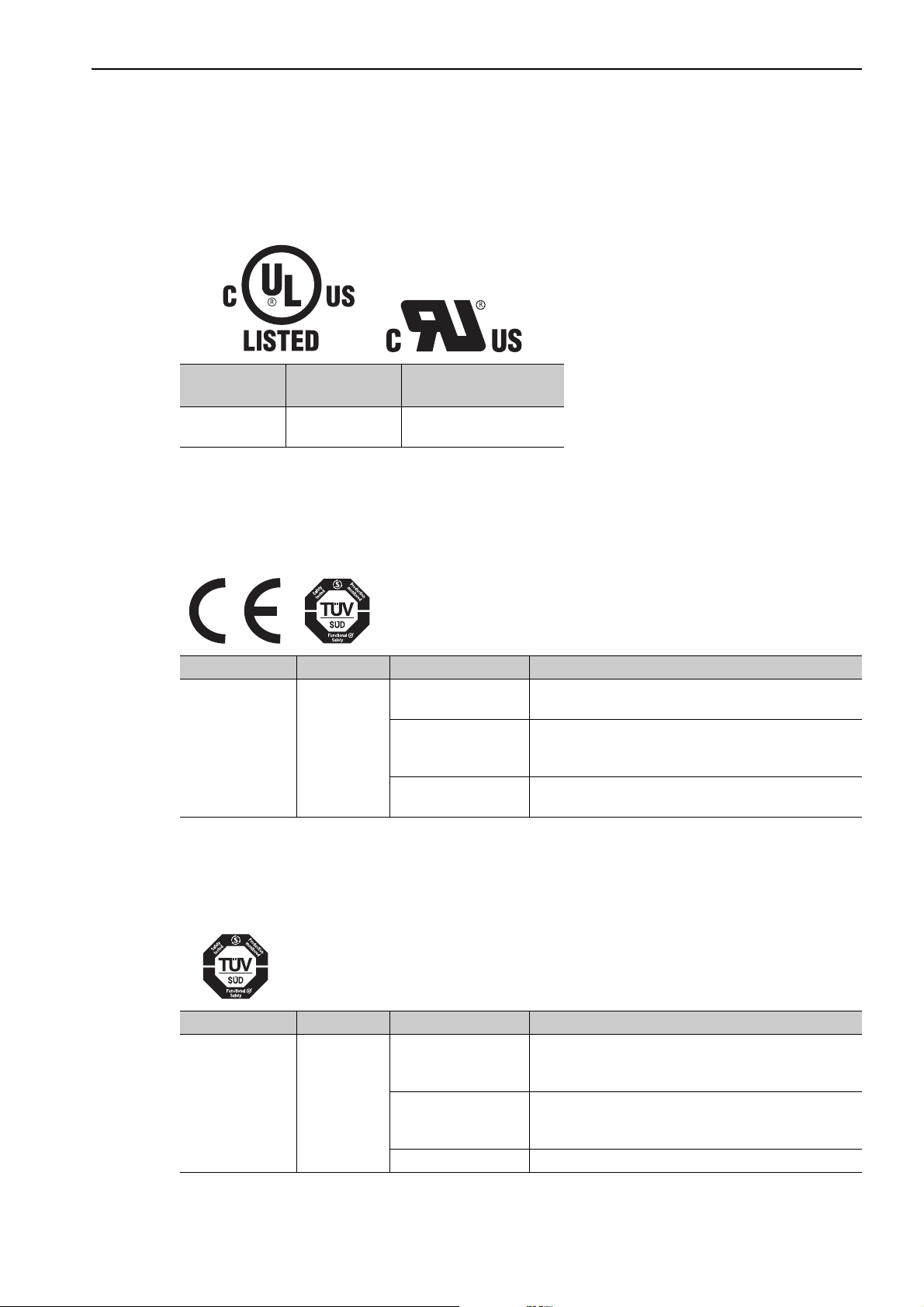
Harmonized Standards
North American Safety Standards (UL)
Model
SERVOPACK
Converter
∗ Underwriters Laboratories Inc.
Note: Applicable when the Safety Module is attached to the SERVOPACKs for use with the analog voltage and pulse train
reference, with the MECHATROLINK-II communications reference, with the MECHATROLINK-III communications reference, and with the command option attachable type.
SGDV
SGDV-COA
UL∗ Standards
(UL File No.)
UL508C (E147823)
European Directives
Model European Directives Harmonized Standards
SERVOPACK
Converter
SGDV
SGDV-COA
Machinery Directive
2006/42/EC
EMC Directive
2004/108/EC
Low Voltage Directive
2006/95/EC
EN ISO13849-1: 2008
EN 954-1
EN 55011 group 1, class A
EN61000-6-2
EN 61800-3
EN 50178
EN 61800-5-1
Note: Applicable when the Safety Module is attached to the SERVOPACKs for use with the analog voltage and pulse train
reference, with the MECHATROLINK-II communications reference, with the MECHATROLINK-III communications reference, and with the command option attachable type.
Safety Standards
Model Safety Standards Standards
EN ISO13849-1: 2008
Safety of Machinery
SERVOPACK SGDV
Functional Safety
EMC IEC 61326-3-1
Note: Applicable when the Safety Module is attached to the SERVOPACKs for use with the analog voltage and pulse train
reference, with the MECHATROLINK-II communications reference, with the MECHATROLINK-III communications reference, and with the command option attachable type.
EN 954-1
IEC 60204-1
IEC 61508 series
IEC 62061
IEC 61800-5-2
xv
Page 16
Safe Performance
Items Standards Performance Level
Safety Integrity Level
Probability of Dangerous Failure per Hour
Category EN 954-1 Category 3
Performance Level EN ISO 13849-1 PL d (Category 2)
Mean Time to Dangerous Failure of Each
Channel
Average Diagnostic Coverage EN ISO 13849-1 DCave: Medium
Stop Category IEC 60204-1 Stop category 0/1/2
Safety Function IEC 61800-5-2 STO/SS1/SS2/SLS
Description of Technical Terms
IEC 61508 SIL2
IEC 62061 SILCL2
IEC 61508
IEC 62061
EN ISO 13849-1 MTTFd: High
PFH ≤ 3.3 ×
(3.3% of SIL2)
10
-7
[1/h]
The following table shows the meanings of terms used in this manual.
Te rm Meaning
Σ-V Series: SGMJV, SGMAV, SGMVV, SGMPS, SGMGV, SGMSV, and SGMCS
Servomotor
SERVOPACK Σ-V Series and Large-Capacity Σ-V Series SGDV SERVOPACKs
Servo Drive A set including a servomotor and SERVOPACK (i.e., a servo amplifier)
Servo System
Analog voltage and pulse train
reference model
M-II communications
reference model
M-III communications
reference model
Command option attachable
type
Safety Option Module
Safety Module The option module that provides safety functions specified in this manual.
Panel Operator
Digital Operator Handy type operator connected to SERVOPACKs
Servo ON Power to motor ON
Servo OFF Power to motor OFF
BaseBlock (BB)
Hardwire BaseBlock Function (HWBB)
Safe Torque Off (STO)
(Direct Drive) servomotor
Linear Σ Series: SGLGW, SGLFW, SGLTW, and SGLC servomotors
A servo control system that includes the combination of a servo drive with a host controller and peripheral devices
Analog voltage and pulse train used for SGDV SERVOPACK interface
MECHATROLINK-II communications reference used for SGDV SERVOPACK interface
MECHATROLINK-III communications reference used for SGDV SERVOPACK interface
SERVOPACK on which a Command Option Module can be installed
General term of option modules that provide safety functions and are mounted on
SGDV SERVOPACKs.
The operator with a panel display that is mounted on analog voltage and pulse-train reference SERVOPACKs.
Power supply to motor is turned OFF by shutting OFF the base current to the power
transistor that supplies power to the motor.
Safety function in the SERVOPACK
This is the safety function that is equivalent to the Safe Torque Off function defined in
IEC 61800-5-2.
This is one of safety functions defined in IEC 61800-5-2.
This is the safety function that shuts OFF power supply to the motor.
xvi
Page 17
Te rm Meaning
This is one of safety functions defined in IEC 61800-5-2.
Safe Stop 1 (SS1)
Safe Stop 2 (SS2)
Safely-Limited Speed (SLS)
Safe BaseBlock Function
(SBB function)
Safe BaseBlock with Delay
Function (SBB-D function)
Safe Position Monitor with
Delay Function
(SPM-D function)
Safely Limited Speed with
Delay Function
(SLS-D function)
Safe (HWBB) state
Safe State
Deceleration Monitoring The Safety Module is monitoring deceleration operation of the motor.
Position Monitoring The Safety Module is monitoring distance that the motor moved.
Constant-speed Monitoring The Safety Module is monitoring constant-speed operation of the motor.
Safety-related Module
Parameter
Safety-related Servo
Parameter
This is the safety function that starts deceleration of the motor and executes the STO
function after a specified time has passed.
This is one of safety functions defined in IEC 61800-5-2.
This is the safety function that starts deceleration of the motor and prevents the motor
from stopping at a distance greater than the allowable deviation from the specified position after a specified time has passed.
This is one of safety functions defined in IEC 61800-5-2.
This is the safety function that prevents the motor speed from exceeding the specified
speed.
This is one of safety functions in the Safety Module.
This is the safety function that is equivalent to the Safe Torque Off function defined in
IEC 61800-5-2.
This is one of safety functions in the Safety Module.
This is the safety function that is equivalent to the Safe Stop 1 function defined in IEC
61800-5-2.
This is one of safety functions in the Safety Module.
This is the safety function that is equivalent to the Safe Stop 2 function defined in IEC
61800-5-2.
Stopping function in the Safety Module.
This is the safety function that is equivalent to the Safely-Limited Speed function
defined in IEC 61800-5-2.
The Safety Module is shutting OFF power supply to the motor by executing the HWBB
function of SGDV SERVOPACK.
Safe state depends on safety functions used.
SBB function
SBB-D function
SPM-D function
SLS-D function
Parameter related to the safety functions of the Safety Module.
These parameters contain the information related to the safety functions of SERVOPACKs and servomotors, and are managed by the Safety Module.
Safe (HWBB) state
Safe (HWBB) state
When monitoring positions or in a safe (HWBB) state
When monitoring constant-speed operation or in a safe (HWBB)
state
(cont’d)
System Reset Reset the servo system by shutting OFF the power or executing software reset (Fn030).
Parameter Recalculation
Proof Test
Recalculation of parameter by CONFIG command via MECHATROLINK-II or by the
request from the Command Option Module.
Scheduled tests defined in IEC 61508-4.
This is the test that is used to detect the failure of the safety-related system.
xvii
Page 18

CONTENTS
About this Manual . . . . . . . . . . . . . . . . . . . . . . . . . . . . . . . . . . . . . . . . . . . . . . . . . . . . . . . . iii
Safety Precautions. . . . . . . . . . . . . . . . . . . . . . . . . . . . . . . . . . . . . . . . . . . . . . . . . . . . . . . vii
Warranty. . . . . . . . . . . . . . . . . . . . . . . . . . . . . . . . . . . . . . . . . . . . . . . . . . . . . . . . . . . . . . . xiii
Harmonized Standards . . . . . . . . . . . . . . . . . . . . . . . . . . . . . . . . . . . . . . . . . . . . . . . . . . . xv
Description of Technical Terms . . . . . . . . . . . . . . . . . . . . . . . . . . . . . . . . . . . . . . . . . . . . . xvi
Chapter 1 Checking Products . . . . . . . . . . . . . . . . . . . . . . . . . . . . . . . . . . .1-1
1.1 Checking Products on Delivery . . . . . . . . . . . . . . . . . . . . . . . . . . . . . . . . . . . 1-2
1.2 Nameplate (Ratings) and Model Designation. . . . . . . . . . . . . . . . . . . . . . . . . 1-3
1.3 Nameplate Location . . . . . . . . . . . . . . . . . . . . . . . . . . . . . . . . . . . . . . . . . . . . 1-3
Chapter 2 Specifications . . . . . . . . . . . . . . . . . . . . . . . . . . . . . . . . . . . . . . .2-1
2.1 Overview . . . . . . . . . . . . . . . . . . . . . . . . . . . . . . . . . . . . . . . . . . . . . . . . . . . . 2-2
2.2 Specifications . . . . . . . . . . . . . . . . . . . . . . . . . . . . . . . . . . . . . . . . . . . . . . . . .2-3
2.3 Part Names . . . . . . . . . . . . . . . . . . . . . . . . . . . . . . . . . . . . . . . . . . . . . . . . . . 2-4
2.4 Internal Block Diagram . . . . . . . . . . . . . . . . . . . . . . . . . . . . . . . . . . . . . . . . . . 2-5
Chapter 3 SERVOPACK Installation . . . . . . . . . . . . . . . . . . . . . . . . . . . . . .3-1
3.1 SERVOPACK Installation Environment and Harmonized Standards . . . . . . . 3-2
3.1.1 Installation Environment. . . . . . . . . . . . . . . . . . . . . . . . . . . . . . . . . . . . . . . . . . . . . . . . . . .3-2
3.1.2 Installation Conditions for Harmonized Standards . . . . . . . . . . . . . . . . . . . . . . . . . . . . . . .3-2
3.2 SERVOPACK Installation . . . . . . . . . . . . . . . . . . . . . . . . . . . . . . . . . . . . . . . . 3-3
3.2.1 Orientation . . . . . . . . . . . . . . . . . . . . . . . . . . . . . . . . . . . . . . . . . . . . . . . . . . . . . . . . . . . . . 3-3
3.2.2 Installation Standards. . . . . . . . . . . . . . . . . . . . . . . . . . . . . . . . . . . . . . . . . . . . . . . . . . . . . 3-4
3.3 EMC Installation Conditions . . . . . . . . . . . . . . . . . . . . . . . . . . . . . . . . . . . . . . 3-6
3.3.1 SGDV-0 (Analog Voltage and Pulse Train Reference Model). . . . . . . . . . . . . 3-6
3.3.2 SGDV-1 (M-II Communications Reference Model). . . . . . . . . . . . . . . . . . . . 3-16
3.3.3 SGDV-2 (M-III Communications Reference Model) . . . . . . . . . . . . . . . . . . . 3-26
3.3.4 SGDV-EA (Command Option Attachable Type). . . . . . . . . . . . . . . . . . . . . . . . 3-36
Chapter 4 Wiring and Connection . . . . . . . . . . . . . . . . . . . . . . . . . . . . . . . . 4-1
4.1 System Configuration Diagram . . . . . . . . . . . . . . . . . . . . . . . . . . . . . . . . . . . 4-2
4.2 I/O Signal Connections. . . . . . . . . . . . . . . . . . . . . . . . . . . . . . . . . . . . . . . . . . 4-3
4.2.1 Terminal Layout . . . . . . . . . . . . . . . . . . . . . . . . . . . . . . . . . . . . . . . . . . . . . . . . . . . . . . . . . 4-3
4.2.2 Electrical Specifications and Connections of Input Circuit . . . . . . . . . . . . . . . . . . . . . . . . . 4-4
4.2.3 Electrical Specifications and Connections of Output Circuit. . . . . . . . . . . . . . . . . . . . . . . .4-5
xviii
Page 19

Chapter 5 Precautions and Basic Settings Required
before Starting Operation . . . . . . . . . . . . . . . . . . . . . . . . . . . . . .5-1
5.1 Safety Precautions for Using the Safety Module . . . . . . . . . . . . . . . . . . . . . . 5-2
5.2 Risk Assessment . . . . . . . . . . . . . . . . . . . . . . . . . . . . . . . . . . . . . . . . . . . . . . 5-3
5.3 Limitations . . . . . . . . . . . . . . . . . . . . . . . . . . . . . . . . . . . . . . . . . . . . . . . . . . . 5-4
5.3.1 Limitations on Lower Limit of Encoder Output Pulses . . . . . . . . . . . . . . . . . . . . . . . . . . . . 5-4
5.3.2 Limitations on the Use of the Test without Motor Function. . . . . . . . . . . . . . . . . . . . . . . . .5-6
5.3.3 Limitations on the Use of an External Encoder . . . . . . . . . . . . . . . . . . . . . . . . . . . . . . . . . 5-6
5.3.4 Device Combination . . . . . . . . . . . . . . . . . . . . . . . . . . . . . . . . . . . . . . . . . . . . . . . . . . . . . .5-6
5.4 Basic Settings Required before Starting Operation . . . . . . . . . . . . . . . . . . . . 5-7
5.5 Checking the Operation . . . . . . . . . . . . . . . . . . . . . . . . . . . . . . . . . . . . . . . . . 5-8
Chapter 6 Safety Functions. . . . . . . . . . . . . . . . . . . . . . . . . . . . . . . . . . . . .6-1
6.1 Overview . . . . . . . . . . . . . . . . . . . . . . . . . . . . . . . . . . . . . . . . . . . . . . . . . . . . 6-2
6.2 Common Items. . . . . . . . . . . . . . . . . . . . . . . . . . . . . . . . . . . . . . . . . . . . . . . . 6-3
6.2.1 Selecting a Safety Function . . . . . . . . . . . . . . . . . . . . . . . . . . . . . . . . . . . . . . . . . . . . . . . .6-3
6.2.2 Safety Request Input Signals. . . . . . . . . . . . . . . . . . . . . . . . . . . . . . . . . . . . . . . . . . . . . . .6-4
6.2.3 External Device Monitor Output Signals . . . . . . . . . . . . . . . . . . . . . . . . . . . . . . . . . . . . . . 6-7
6.2.4 Operations After Alarms and Resetting Systems, and While Recalculating Parameters. 6-10
6.3 Safe BaseBlock Function (SBB Function) . . . . . . . . . . . . . . . . . . . . . . . . . . 6-11
6.3.1 Basic Operation . . . . . . . . . . . . . . . . . . . . . . . . . . . . . . . . . . . . . . . . . . . . . . . . . . . . . . . . 6-11
6.3.2 Settings . . . . . . . . . . . . . . . . . . . . . . . . . . . . . . . . . . . . . . . . . . . . . . . . . . . . . . . . . . . . . . 6-11
6.3.3 Returning Method. . . . . . . . . . . . . . . . . . . . . . . . . . . . . . . . . . . . . . . . . . . . . . . . . . . . . . . 6-11
6.3.4 Exceptional Operation . . . . . . . . . . . . . . . . . . . . . . . . . . . . . . . . . . . . . . . . . . . . . . . . . . .6-12
6.3.5 Related SERVOPACK Functions . . . . . . . . . . . . . . . . . . . . . . . . . . . . . . . . . . . . . . . . . . . 6-13
6.4 Safe BaseBlock with Delay Function (SBB-D Function) . . . . . . . . . . . . . . . 6-17
6.4.1 Basic Operation . . . . . . . . . . . . . . . . . . . . . . . . . . . . . . . . . . . . . . . . . . . . . . . . . . . . . . . . 6-17
6.4.2 Settings . . . . . . . . . . . . . . . . . . . . . . . . . . . . . . . . . . . . . . . . . . . . . . . . . . . . . . . . . . . . . . 6-19
6.4.3 Returning Method. . . . . . . . . . . . . . . . . . . . . . . . . . . . . . . . . . . . . . . . . . . . . . . . . . . . . . . 6-19
6.4.4 Exceptional Operation . . . . . . . . . . . . . . . . . . . . . . . . . . . . . . . . . . . . . . . . . . . . . . . . . . .6-19
6.4.5 Related SERVOPACK Functions . . . . . . . . . . . . . . . . . . . . . . . . . . . . . . . . . . . . . . . . . . . 6-20
6.5 Safe Position Monitor with Delay Function (SPM-D Function). . . . . . . . . . . 6-21
6.5.1 Basic Operation . . . . . . . . . . . . . . . . . . . . . . . . . . . . . . . . . . . . . . . . . . . . . . . . . . . . . . . . 6-21
6.5.2 Settings . . . . . . . . . . . . . . . . . . . . . . . . . . . . . . . . . . . . . . . . . . . . . . . . . . . . . . . . . . . . . . 6-23
6.5.3 Returning Method. . . . . . . . . . . . . . . . . . . . . . . . . . . . . . . . . . . . . . . . . . . . . . . . . . . . . . . 6-23
6.5.4 Exceptional Operation . . . . . . . . . . . . . . . . . . . . . . . . . . . . . . . . . . . . . . . . . . . . . . . . . . .6-23
6.5.5 Related SERVOPACK Functions . . . . . . . . . . . . . . . . . . . . . . . . . . . . . . . . . . . . . . . . . . . 6-24
6.6 Safely Limited Speed with Delay Function (SLS-D Function) . . . . . . . . . . . 6-25
6.6.1 Basic Operation . . . . . . . . . . . . . . . . . . . . . . . . . . . . . . . . . . . . . . . . . . . . . . . . . . . . . . . . 6-25
6.6.2 Settings . . . . . . . . . . . . . . . . . . . . . . . . . . . . . . . . . . . . . . . . . . . . . . . . . . . . . . . . . . . . . . 6-27
6.6.3 Returning Method. . . . . . . . . . . . . . . . . . . . . . . . . . . . . . . . . . . . . . . . . . . . . . . . . . . . . . . 6-27
6.6.4 Exceptional Operation . . . . . . . . . . . . . . . . . . . . . . . . . . . . . . . . . . . . . . . . . . . . . . . . . . .6-27
6.6.5 Related SERVOPACK Functions . . . . . . . . . . . . . . . . . . . . . . . . . . . . . . . . . . . . . . . . . . . 6-28
6.7 Order of Priority of Safety Functions . . . . . . . . . . . . . . . . . . . . . . . . . . . . . . 6-29
6.8 Application Example of Safety Functions. . . . . . . . . . . . . . . . . . . . . . . . . . . 6-31
xix
Page 20

Chapter 7 Setting Parameters. . . . . . . . . . . . . . . . . . . . . . . . . . . . . . . . . . .7-1
7.1 Types of Parameters . . . . . . . . . . . . . . . . . . . . . . . . . . . . . . . . . . . . . . . . . . . 7-2
7.2 Safety-related Module Parameters. . . . . . . . . . . . . . . . . . . . . . . . . . . . . . . . . 7-3
7.2.1 Overview . . . . . . . . . . . . . . . . . . . . . . . . . . . . . . . . . . . . . . . . . . . . . . . . . . . . . . . . . . . . . . 7-3
7.2.2 Operation Procedures . . . . . . . . . . . . . . . . . . . . . . . . . . . . . . . . . . . . . . . . . . . . . . . . . . . .7-4
7.3 Safety-related Servo Parameters . . . . . . . . . . . . . . . . . . . . . . . . . . . . . . . . . . 7-7
7.3.1 Overview . . . . . . . . . . . . . . . . . . . . . . . . . . . . . . . . . . . . . . . . . . . . . . . . . . . . . . . . . . . . . . 7-7
7.3.2 Operation Procedures . . . . . . . . . . . . . . . . . . . . . . . . . . . . . . . . . . . . . . . . . . . . . . . . . . . .7-8
Chapter 8 Utility Functions . . . . . . . . . . . . . . . . . . . . . . . . . . . . . . . . . . . . .8-1
8.1 List of Utility Functions . . . . . . . . . . . . . . . . . . . . . . . . . . . . . . . . . . . . . . . . . . 8-2
8.2 Safety Option Module Access Mode Setting (Fn040) . . . . . . . . . . . . . . . . . .8-3
8.2.1 Overview . . . . . . . . . . . . . . . . . . . . . . . . . . . . . . . . . . . . . . . . . . . . . . . . . . . . . . . . . . . . . . 8-3
8.2.2 Operation Procedures . . . . . . . . . . . . . . . . . . . . . . . . . . . . . . . . . . . . . . . . . . . . . . . . . . . .8-3
8.3 Safety-related Module Parameter Setting (Fn041). . . . . . . . . . . . . . . . . . . . . 8-5
8.3.1 Overview . . . . . . . . . . . . . . . . . . . . . . . . . . . . . . . . . . . . . . . . . . . . . . . . . . . . . . . . . . . . . . 8-5
8.3.2 Operation Procedures . . . . . . . . . . . . . . . . . . . . . . . . . . . . . . . . . . . . . . . . . . . . . . . . . . . .8-6
8.4 Safety-related Servo Parameter Updating (Fn042) . . . . . . . . . . . . . . . . . . . . 8-8
8.4.1 Overview . . . . . . . . . . . . . . . . . . . . . . . . . . . . . . . . . . . . . . . . . . . . . . . . . . . . . . . . . . . . . . 8-8
8.4.2 Operation Procedures . . . . . . . . . . . . . . . . . . . . . . . . . . . . . . . . . . . . . . . . . . . . . . . . . . . .8-8
8.5 Safety Option Module Initializing Parameter Setting (Fn043) . . . . . . . . . . .8-12
8.5.1 Overview . . . . . . . . . . . . . . . . . . . . . . . . . . . . . . . . . . . . . . . . . . . . . . . . . . . . . . . . . . . . . 8-12
8.5.2 Operation Procedures . . . . . . . . . . . . . . . . . . . . . . . . . . . . . . . . . . . . . . . . . . . . . . . . . . .8-12
8.6 Safety Option Module Setup Alarm Clear (Fn044). . . . . . . . . . . . . . . . . . . . 8-14
8.6.1 Overview . . . . . . . . . . . . . . . . . . . . . . . . . . . . . . . . . . . . . . . . . . . . . . . . . . . . . . . . . . . . . 8-14
8.6.2 Operation Procedures . . . . . . . . . . . . . . . . . . . . . . . . . . . . . . . . . . . . . . . . . . . . . . . . . . .8-15
8.7 Related Utility Functions. . . . . . . . . . . . . . . . . . . . . . . . . . . . . . . . . . . . . . . . 8-17
8.7.1 Software Version Display (Fn012) . . . . . . . . . . . . . . . . . . . . . . . . . . . . . . . . . . . . . . . . . . 8-17
8.7.2 Resetting Configuration Error in Option Modules (Fn014) . . . . . . . . . . . . . . . . . . . . . . . . 8-17
8.7.3 Display of SERVOPACK and Servomotor ID (Fn01E) . . . . . . . . . . . . . . . . . . . . . . . . . . . 8-17
Chapter 9 Monitor Mode . . . . . . . . . . . . . . . . . . . . . . . . . . . . . . . . . . . . . . .9-1
9.1 Overview . . . . . . . . . . . . . . . . . . . . . . . . . . . . . . . . . . . . . . . . . . . . . . . . . . . . 9-2
9.1.1 List of Monitor Modes. . . . . . . . . . . . . . . . . . . . . . . . . . . . . . . . . . . . . . . . . . . . . . . . . . . . . 9-2
9.1.2 Status Display . . . . . . . . . . . . . . . . . . . . . . . . . . . . . . . . . . . . . . . . . . . . . . . . . . . . . . . . . . 9-3
9.2 Monitoring from the Panel Operator and Digital Operator . . . . . . . . . . . . . . . 9-5
9.2.1 Safety Module I/O Signal Monitor (Un016) . . . . . . . . . . . . . . . . . . . . . . . . . . . . . . . . . . . . 9-5
9.2.2 Safety Module Safety Function Status (Un017) . . . . . . . . . . . . . . . . . . . . . . . . . . . . . . . . .9-5
9.2.3 Safety Module System Status (Un018) . . . . . . . . . . . . . . . . . . . . . . . . . . . . . . . . . . . . . . . 9-6
9.2.4 Time until Arrival at Safety Speed (Un019 and Un01A) . . . . . . . . . . . . . . . . . . . . . . . . . . . 9-7
9.2.5 Active Mode Reference Speed (Un01B) . . . . . . . . . . . . . . . . . . . . . . . . . . . . . . . . . . . . . . 9-8
9.2.6 Safety Module Motor Speed (Un01C) . . . . . . . . . . . . . . . . . . . . . . . . . . . . . . . . . . . . . . . . 9-8
9.2.7 Safety Module Motor Position (Un01D) . . . . . . . . . . . . . . . . . . . . . . . . . . . . . . . . . . . . . . . 9-8
9.2.8 Safety Module Monitoring Speed (Un01E, Un01F) . . . . . . . . . . . . . . . . . . . . . . . . . . . . . .9-8
9.3 Monitoring Over the Network . . . . . . . . . . . . . . . . . . . . . . . . . . . . . . . . . . . . . 9-9
9.3.1 SERVOPACK for Use with MECHATROLINK-II Communications Reference. . . . . . . . . . 9-9
9.3.2 SERVOPACK for Use with MECHATROLINK-III Communications Reference . . . . . . . . 9-10
9.3.3 SERVOPACK for Use with Command Option Module . . . . . . . . . . . . . . . . . . . . . . . . . . . 9-10
xx
Page 21

Chapter 10 Active Mode Function . . . . . . . . . . . . . . . . . . . . . . . . . . . . . . .10-1
10.1 Overview . . . . . . . . . . . . . . . . . . . . . . . . . . . . . . . . . . . . . . . . . . . . . . . . . . 10-2
10.2 Basic Functions . . . . . . . . . . . . . . . . . . . . . . . . . . . . . . . . . . . . . . . . . . . . . 10-2
10.2.1 Internal Deceleration References. . . . . . . . . . . . . . . . . . . . . . . . . . . . . . . . . . . . . . . . . .10-3
10.2.2 Active Mode Hold Time . . . . . . . . . . . . . . . . . . . . . . . . . . . . . . . . . . . . . . . . . . . . . . . . . 10-3
10.2.3 Position Error Level for Releasing Active Mode. . . . . . . . . . . . . . . . . . . . . . . . . . . . . . . 10-4
10.2.4 Speed Reference Level for Releasing Active Mode. . . . . . . . . . . . . . . . . . . . . . . . . . . .10-5
10.2.5 Monitoring Active Mode Function. . . . . . . . . . . . . . . . . . . . . . . . . . . . . . . . . . . . . . . . . . 10-6
10.3 Settings . . . . . . . . . . . . . . . . . . . . . . . . . . . . . . . . . . . . . . . . . . . . . . . . . . 10-10
10.4 Returning Method . . . . . . . . . . . . . . . . . . . . . . . . . . . . . . . . . . . . . . . . . . 10-11
10.4.1 Returning Conditions . . . . . . . . . . . . . . . . . . . . . . . . . . . . . . . . . . . . . . . . . . . . . . . . . . 10-11
10.4.2 SERVOPACK for Use with Analog Voltage and Pulse Train Reference . . . . . . . . . . . 10-11
10.4.3 SERVOPACK for Use with MECHATROLINK-II Communications Reference. . . . . . . 10-13
10.4.4 SERVOPACK for Use with MECHATROLINK-III Communications Reference . . . . . . 10-15
10.4.5 SERVOPACK for Use with Command Option Module . . . . . . . . . . . . . . . . . . . . . . . . . 10-16
10.5 Exceptional Operation . . . . . . . . . . . . . . . . . . . . . . . . . . . . . . . . . . . . . . . 10-17
10.6 Related SERVOPACK Functions . . . . . . . . . . . . . . . . . . . . . . . . . . . . . . . 10-18
10.6.1 Utility Functions . . . . . . . . . . . . . . . . . . . . . . . . . . . . . . . . . . . . . . . . . . . . . . . . . . . . . . 10-18
10.6.2 Overtravel. . . . . . . . . . . . . . . . . . . . . . . . . . . . . . . . . . . . . . . . . . . . . . . . . . . . . . . . . . . 10-19
10.6.3 Servo ON Command . . . . . . . . . . . . . . . . . . . . . . . . . . . . . . . . . . . . . . . . . . . . . . . . . . 10-19
10.6.4 Zero-clamp Function . . . . . . . . . . . . . . . . . . . . . . . . . . . . . . . . . . . . . . . . . . . . . . . . . . 10-19
10.6.5 Speed Feedforward Function . . . . . . . . . . . . . . . . . . . . . . . . . . . . . . . . . . . . . . . . . . . . 10-19
10.6.6 Torque Feedforward Function . . . . . . . . . . . . . . . . . . . . . . . . . . . . . . . . . . . . . . . . . . . 10-19
Chapter 11 Troubleshooting . . . . . . . . . . . . . . . . . . . . . . . . . . . . . . . . . . . 11-1
11.1 List of Alarms . . . . . . . . . . . . . . . . . . . . . . . . . . . . . . . . . . . . . . . . . . . . . . . 11-2
11.2 Troubleshooting of Alarms . . . . . . . . . . . . . . . . . . . . . . . . . . . . . . . . . . . . . 11-3
Chapter 12 Appendix. . . . . . . . . . . . . . . . . . . . . . . . . . . . . . . . . . . . . . . . .12-1
12.1 Safety-related Module Parameters . . . . . . . . . . . . . . . . . . . . . . . . . . . . . . 12-2
12.2 Safety-related Servo Parameters. . . . . . . . . . . . . . . . . . . . . . . . . . . . . . . . 12-4
12.3 Parameters Related Active Mode Function . . . . . . . . . . . . . . . . . . . . . . . . 12-6
12.4 Device Combinations . . . . . . . . . . . . . . . . . . . . . . . . . . . . . . . . . . . . . . . . . 12-8
12.4.1 SERVOPACKs . . . . . . . . . . . . . . . . . . . . . . . . . . . . . . . . . . . . . . . . . . . . . . . . . . . . . . . .12-8
12.4.2 Servomotors. . . . . . . . . . . . . . . . . . . . . . . . . . . . . . . . . . . . . . . . . . . . . . . . . . . . . . . . . . 12-8
12.4.3 Serial Converter Units . . . . . . . . . . . . . . . . . . . . . . . . . . . . . . . . . . . . . . . . . . . . . . . . .12-10
Index. . . . . . . . . . . . . . . . . . . . . . . . . . . . . . . . . . . . . . . . . . . . . . . . . . . Index-1
Revision History
xxi
Page 22

Checking Products
1
Checking Products
This chapter describes how to check products upon delivery.
1.1 Checking Products on Delivery . . . . . . . . . . . . . . . . . . . . . . . . . . . . . . . . .1-2
1.2 Nameplate (Ratings) and Model Designation . . . . . . . . . . . . . . . . . . . . . .1-3
1.3 Nameplate Location . . . . . . . . . . . . . . . . . . . . . . . . . . . . . . . . . . . . . . . . . 1-3
1-1
Page 23
1 Checking Products
1.1 Checking Products on Delivery
When the Safety Module is Not Connected to the SERVOPACK
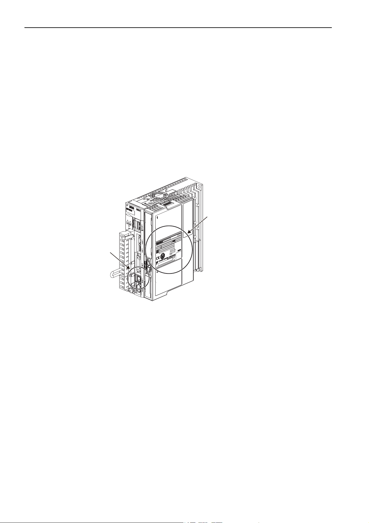
1. Check the nameplate (ratings) to confirm that the product is the one that was ordered.
For the nameplate (ratings), refer to 1.2 Nameplate (Ratings) and Model Designation.
2. Mount the Safety Module to the SERVOPACK as described in the enclosed
Series for Large-Capacity Models Safety Option Module Installation Guide.
For the location of the nameplate, refer to 1.3 Nameplate Location.
3. Remove the safety function jumper connector from the connector (CN8) of the SERVOPACK.
When the Safety Module is Connected to the SERVOPACK
1. Check the nameplate (ratings) to confirm that the Module that is mounted is the Safety Module.
2. Check that the safety function jumper connector is not connected to the connector (CN8) of the
SERVOPACK.
Σ
-V Series/Σ-V
CN8
Nameplate (Ratings)
1-2
Page 24
1.2 Nameplate (Ratings) and Model Designation
Checking Products
Application Module model number
Name
Manufacturing number
Nameplate
(Ratings)
Nameplate
(Model no.)
Nameplate
(Component code)
1.2 Nameplate (Ratings) and Model Designation
Nameplate (Ratings) Example
Model Designation
SGDV – OS A01 A
Series
SGDV
Σ-V Series
1st + 2nd digits: Module Type
Code
OS
Safety option module
Module
1.3 Nameplate Location
6th digit: Design Revision Order
3rd + 4th + 5th digits: Interface Specifications
Code
A01
Interface
Safety module
1-3
Page 25

Specifications
2
Specifications
This chapter gives an overview and describes the specifications of the Safety Module.
2.1 Overview . . . . . . . . . . . . . . . . . . . . . . . . . . . . . . . . . . . . . . . . . . . . . . . . . . 2-2
2.2 Specifications . . . . . . . . . . . . . . . . . . . . . . . . . . . . . . . . . . . . . . . . . . . . . . . 2-3
2.3 Part Names . . . . . . . . . . . . . . . . . . . . . . . . . . . . . . . . . . . . . . . . . . . . . . . . 2-4
2.4 Internal Block Diagram . . . . . . . . . . . . . . . . . . . . . . . . . . . . . . . . . . . . . . . .2-5
2-1
Page 26
2 Specifications
2.1 Overview
The Safety Module is an Option Module that is connected to a Σ-V-series or Large-Capacity Σ-V Series SERVOPACK. By using the Hard Wire BaseBlock function of the SERVOPACK, the following four safety func-
tions, which are defined in functional safety standards, can be achieved.
Safe BaseBlock Function
(SBB function)
Safe BaseBlock with Delay Function
(SBB-D function)
Safe Position Monitor with Delay Function
(SPM-D function)
Safely Limited Speed with Delay Function
(SLS-D function)
Function Remarks
This is a safety function that is equivalent to the Safe Torque Off
function defined in IEC 61800-5-2.
This is a safety function that is equivalent to the Safe Stop 1 function defined in IEC 61800-5-2.
This is a safety function that is equivalent to the Safe Stop 2 function defined in IEC 61800-5-2.
This is a safety function that is equivalent to the Safely-Limited
Speed function defined in IEC 61800-5-2.
2-2
Page 27
Specifications
2.2 Specifications
This table lists the general specifications of the Safety Module.
Rotational
motor
Σ-V Series
Applicable SERVOPACK
Placement Attached to the SERVOPACK
Power
Specification
Operating
Conditions
Safety
Functions
Stopping Methods
Others Active Mode Function
Response Time Max. 200 ms
Proof Test Interval 10 years
Power Supply Method Supplied from the control power supply of the SGDV SERVOPACK.
Surrounding Air/Storage
Temperature
Ambient/Storage
Humidity
Vibration/Shock
Resistance
Protection Class/
Pollution Degree
Altitude 1000 m or less
Others
Number of Functions: 2
Inputs
Safety
Function A
Output
Inputs
Safety
Function B
Output
/Σ-V Series for
Large-Capacity
Models
Linear
motor
0°C to +55°C/ -20°C to +85°C
90% RH or less (with no condensation)
2
4.9 m/s
Protection class: IP10, Pollution degree: 2
An environment that satisfies the following conditions.
• Free of corrosive or explosive gases
• Free of exposure to water, oil or chemicals
• Free of dust, salts or iron dust
Free of static electricity, strong electromagnetic fields, magnetic fields or exposure to
radioactivity
Number of Channels 2
Function Safety Request Input Signal (SRI-A1, SRI-A2)
Number of Channels 1
Function External Device Monitor Output Signal (EDM-A)
Number of Channels 2
Function Safety Request Input Signal (SRI-B1, SRI-B2)
Number of Channels 1
Function External Device Monitor Output Signal (EDM-B)
Safe Torque Off (STO) Safe BaseBlock Function (SBB function)
Safe Stop 1 (SS1)
Safe Stop 2 (SS2)
Safety-Limited Speed (SLS)
/ 19.6 m/s
Safety Functions
(IEC61800-5-2)
2
2.2 Specifications
SGDV-01
(analog voltage and pulse train reference model)
SGDV-11
(M-II communications reference model)
SGDV-E1
(command option attachable type)
SGDV-21
(M-III communications reference model)
SGDV-05
(analog voltage and pulse train reference model)
SGDV-15
(M-II communications reference model)
SGDV-E5
(command option attachable type)
SGDV-25
(M-III communications reference model)
Function names of Safety Module
Safe BaseBlock with Delay Function
(SBB-D function)
Safe Position Monitor with Delay Function
(SPM-D function)
Safely Limited Speed with Delay Function
(SLS-D function)
2-3
Page 28
2 Specifications
I/O connector for the Safety Function A (CN21)
I/O connector for the Safety Function B (CN22)
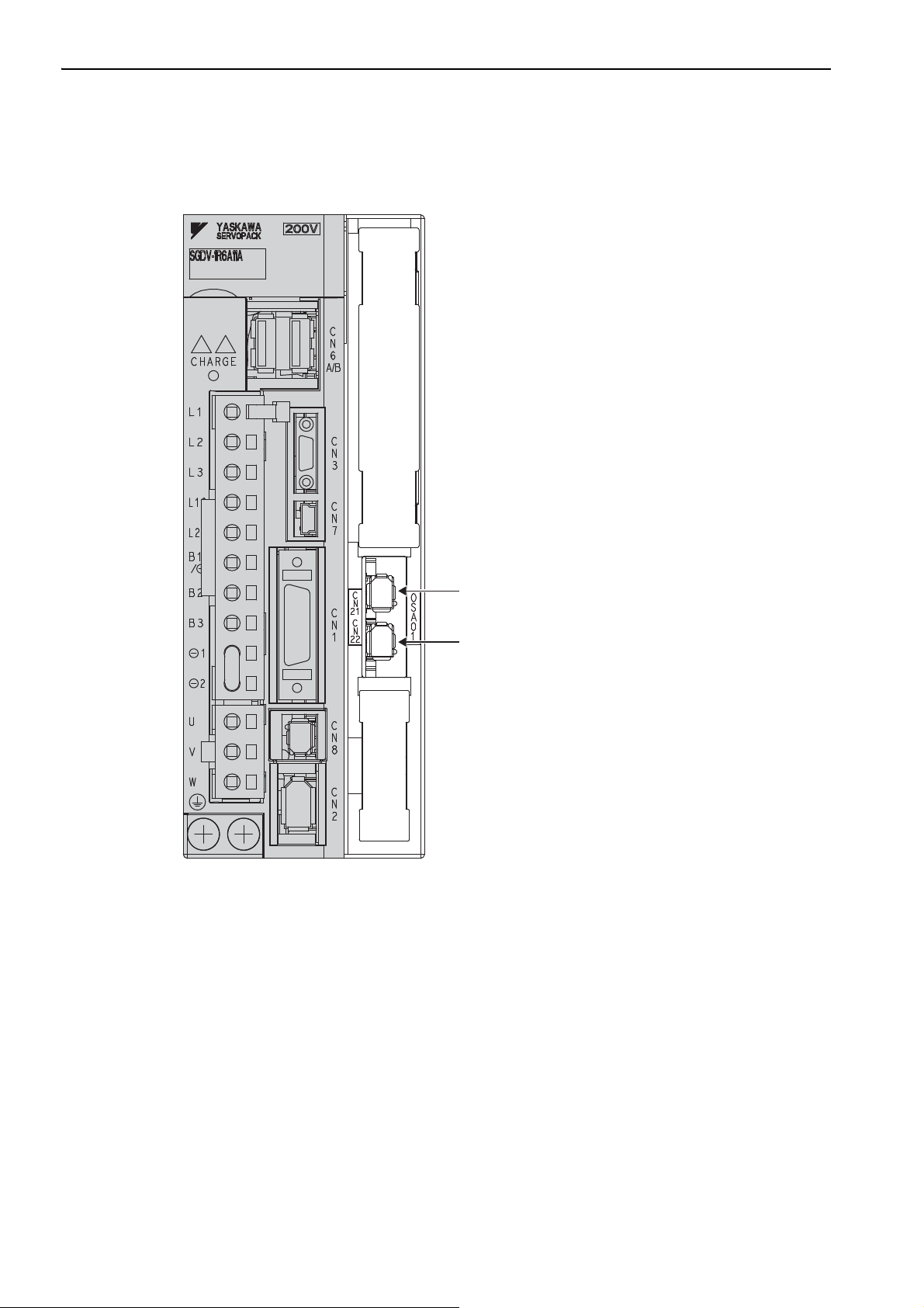
2.3 Part Names
The following figure shows the part names of the Safety Module.
2-4
Note: For the names of the SERVOPACK parts, refer to the user’s manual for the SERVOPACK being used.
Page 29
Specifications
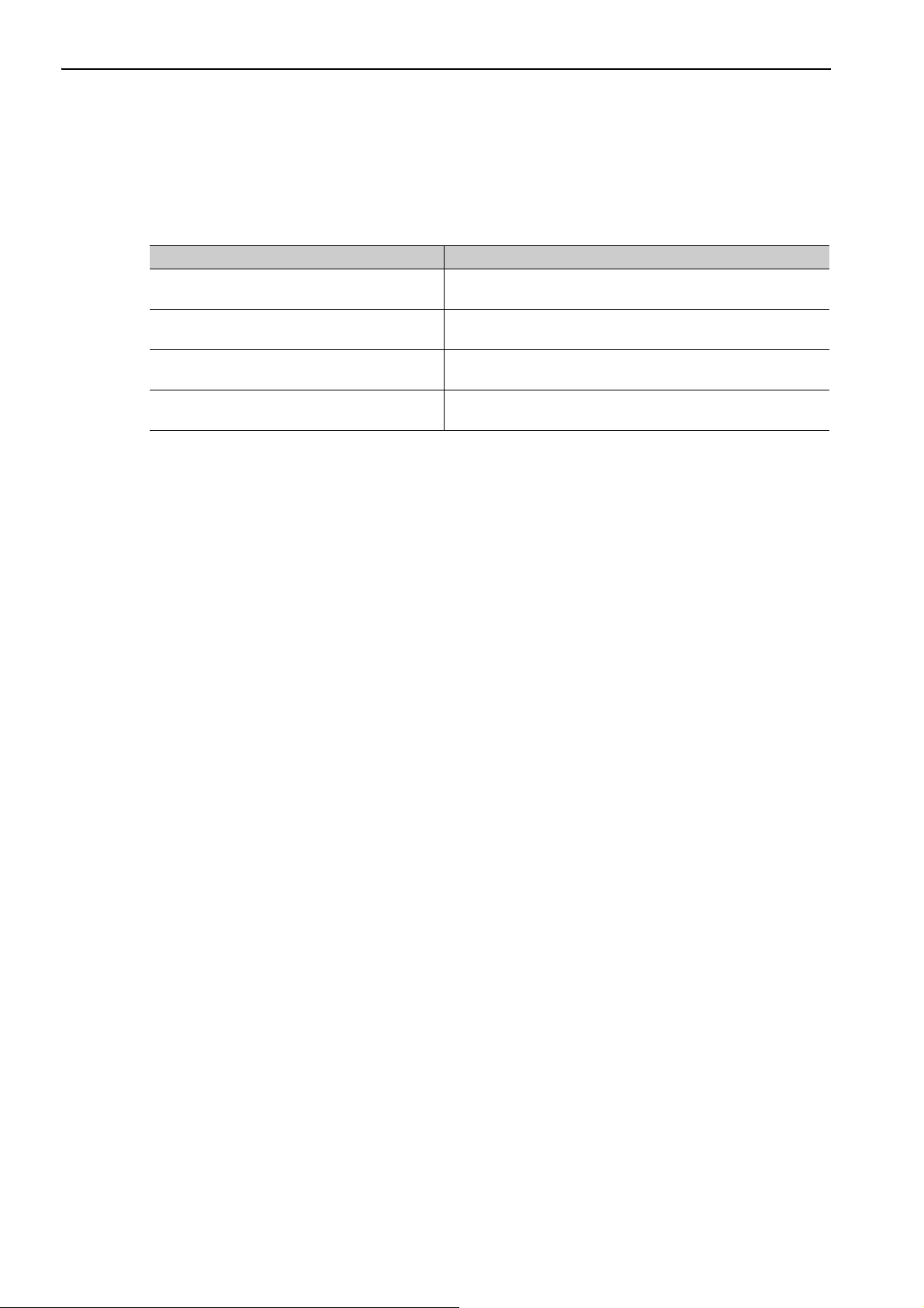
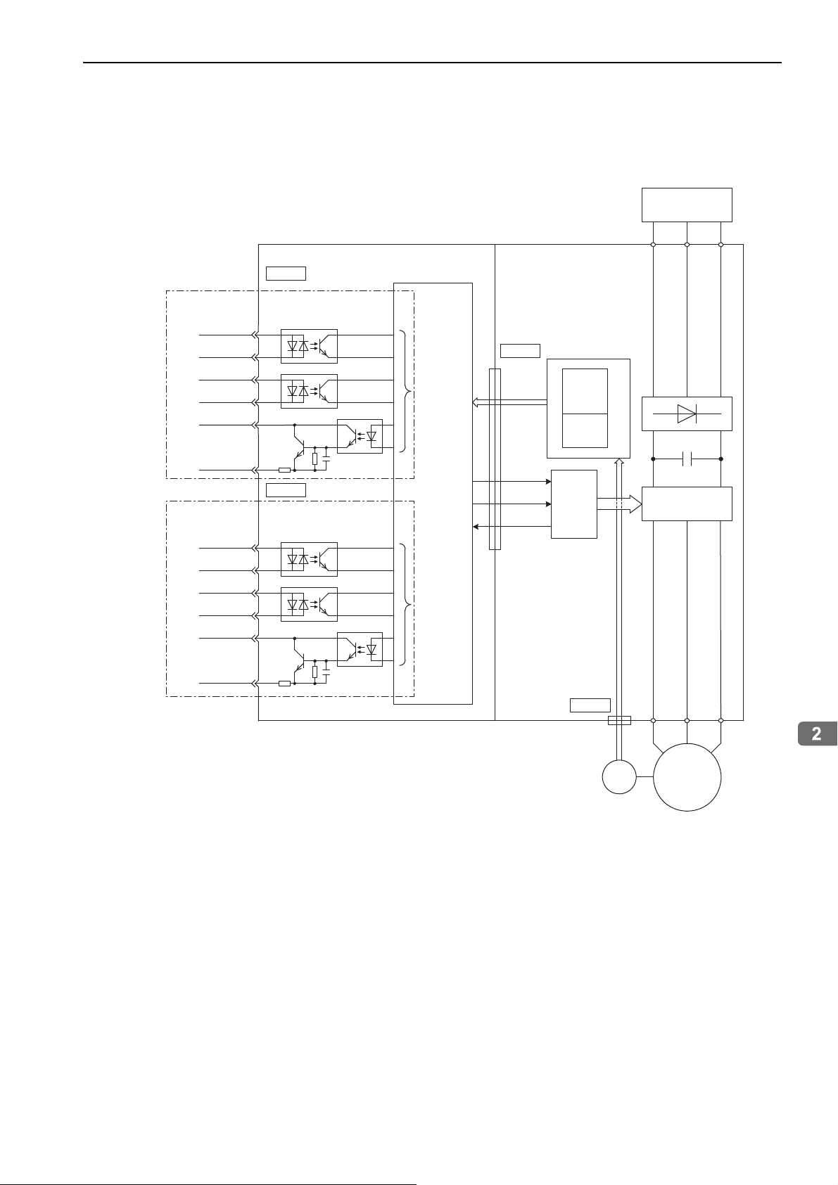
2.4 Internal Block Diagram
This figure shows a typical internal block diagram.
2.4 Internal Block Diagram
Power supply
Safety Function A
/SRI-A1+
/SRI-A1–
/SRI-A2+
/SRI-A2–
/EDM-A+
/EDM-A–
Safety Function B
/SRI-B1+
/SRI-B1–
/SRI-B2+
/SRI-B2–
/EDM-B+
Safety Module
CN21
4
3
6
5
8
7
CN22
4
3
6
5
8
Block A
Safety
function
Block B
SERVOPACK
CN11
HWBB1
HWBB2
EDM1
HWBB
CPU
SERVOޓ
ASIC
Power module
/EDM-B–
7
CN2
ENC
M
2-5
Page 30

SERVOPACK Installation
3
SERVOPACK Installation
This chapter describes how to install the SERVOPACK.
3.1 SERVOPACK Installation Environment and Harmonized Standards . . . . 3-2
3.1.1 Installation Environment . . . . . . . . . . . . . . . . . . . . . . . . . . . . . . . . . . . . . . . . . . . . . . . 3-2
3.1.2 Installation Conditions for Harmonized Standards . . . . . . . . . . . . . . . . . . . . . . . . . . . 3-2
3.2 SERVOPACK Installation . . . . . . . . . . . . . . . . . . . . . . . . . . . . . . . . . . . . .3-3
3.2.1 Orientation . . . . . . . . . . . . . . . . . . . . . . . . . . . . . . . . . . . . . . . . . . . . . . . . . . . . . . . . . . 3-3
3.2.2 Installation Standards . . . . . . . . . . . . . . . . . . . . . . . . . . . . . . . . . . . . . . . . . . . . . . . . .3-4
3.3 EMC Installation Conditions . . . . . . . . . . . . . . . . . . . . . . . . . . . . . . . . . . . 3-6
3.3.1 SGDV-0 (Analog Voltage and Pulse Train Reference Model) . . . . . . . . . 3-6
3.3.2 SGDV-1 (M-II Communications Reference Model) . . . . . . . . . . . . . . . . 3-16
3.3.3 SGDV-2 (M-III Communications Reference Model) . . . . . . . . . . . . . . . 3-26
3.3.4 SGDV-EA (Command Option Attachable Type) . . . . . . . . . . . . . . . . . . . . 3-36
3-1
Page 31

3 SERVOPACK Installation
3.1.1 Installation Environment
3.1 SERVOPACK Installation Environment and Harmonized Standards
SERVOPACK installation environment and harmonized standards are as follows.
3.1.1 Installation Environment
Surrounding air temperature: 0 to 55°C
Ambient humidity: 90% RH or less (with no condensation)
Altitude: 1,000 m or less
Vibration resistance: 4.9 m/s
Shock resistance: 19.6 m/s
Installation Precautions
• Mounting in a Control Panel
To prevent the temperature around the SERVOPACK from exceeding 55°C, take into account the size of the
control panel, the layout of the SERVOPACK, and the cooling method. For details, refer to 3.2 SERVOPACK
Installation.
2
2
• Mounting Near a Heating Unit
To prevent the temperature around the SERVOPACK from exceeding 55°C, suppress radiant heat from the
heating unit and temperature rise due to convection.
• Mounting Near a Vibration Source
To prevent vibration from being transmitted to the SERVOPACK, install a vibration isolator underneath the
SERVOPACK.
• Mounting to a Location Exposed to Corrosive Gas
Take measures to prevent exposure to corrosive gas. Corrosive gases will not immediately affect the SERVOPACK, but will eventually cause electronic components and contactor-related devices to malfunction.
• Other Locations
Do not mount the SERVOPACK in locations subject to high temperatures, high humidity, dripping water, cutting oil, dust, iron filings, or radiation.
<Note>
When storing the SERVOPACK with the power OFF, store it in an environment with the following temperature and humidity:
•-20 to +85°C, 90% RH or less (with no condensation)
3.1.2 Installation Conditions for Harmonized Standards
UL508C
Harmonized
Standards
Operating
Conditions
Installation
Conditions
EN50178, EN55011 group1 classA, EN61000-6-2, EN61800-3, EN61800-5-1, EN954-1
EN ISO13849-1, IEC 60204-1, IEC61326-3-1, IEC 61508 series,
IEC61800-5-2, IEC62061
Overvoltage category: III
Pollution degree: 2
Protection class: IP10
UL Standard and Low Voltage Directive:
Satisfy the conditions outlined in
SGDV Safety Precautions.
EMC Directive:
Certification is required after installation in the user’s machine under the conditions outlined in
3.3 EMC Installation Conditions.
Σ
-V Series or Large-Capacity Σ-V Series AC SERVOPACK
3-2
Page 32

SERVOPACK Installation
3.2 SERVOPACK Installation
Rack
Air flow
3.2.1 Orientation
The SERVOPACK is available in models that are base-mounted, models that are rack-mounted, and models
that are duct-ventilated. In any case, mount the SERVOPACK with a vertical orientation.
Firmly secure the SERVOPACK to the mounting surface, using either two or four mounting holes depending
on the SERVOPACK capacity.
• Base-mounted
3.2 SERVOPACK Installation
Base
• Rack-mounted
• Duct-ventilated
Air flow
Duct
Air flow
3-3
Page 33

3 SERVOPACK Installation
50 mm or more 5 mm
100 mm or more
120 mm or more
120 mm or more
5 mm
Fan
Fan
3.2.2 Installation Standards
3.2.2 Installation Standards
Observe the standards for mounting SERVOPACKs in control panels, including those for the mounting SERVOPACKs side by side in one control panel as shown in the following illustration.
• SERVOPACK Mounting Orientation
Mount the SERVOPACK vertically to the wall, with the front panel (the side with the panel operator display)
facing out.
• Cooling
Refer to the following diagram and leave sufficient space for cooling by fans and natural convection.
• Mounting SERVOPACKs Side by Side in a Control Panel
30 mm or more
Fan Fan
Width varies with
SERVOPACK model.
40 mm or more
40 mm or more
Leave sufficient space on each side and at the top and the bottom of each SERVOPACK. The width on each
side varies in accordance with the models of the SERVOPACKs used.
SERVOPACK Model SGDV-
R70F, R90F, 2R1F, R70A, R90A, 1R6A, 2R8A 1 mm or more
2R8F, 3R8A, 5R5A, 7R6A 1 mm or more 10 mm or more
120A, 180A, 200A, 330A, 470A, 550A, 590A, 780A,
1R9D, 3R5D, 5R4D, 8R4D, 120D, 170D, 210D, 260D,
280D, 370D
Left Right
Side
10 mm or more
Top and bottom
40 mm or more
3-4
Also install cooling fans above the SERVOPACKs to disperse local pockets of warmer air around the SERVOPA CK s.
• Large-Capacity Σ-V Series
Also install cooling fans above the SERVOPACKs and converters to disperse local pockets of warmer air
around them.
Page 34

3.2 SERVOPACK Installation
SERVOPACK Installation
• Inside the Control Panel
The conditions inside the control panel should be the same as the environmental conditions of the SERVOPAC K . Re f er t o 3.1.1 Installation Environment.
3-5
Page 35

3 SERVOPACK Installation
U, V, W
L1, L2
L1C, L2C
CN2
CN1
PE
PE
1
3
4
5
CN8
Safety
controller
2
CN21, CN22
Safety Module
Power supply:
Single-phase 100 VAC
Encoder
Servomotor
Brake
Noise
filter
Brake power
supply
Surge
absorber
Two turn
Two turn
Core Core
Core
Core
Core
Host
controller
Clamp
ClampClamp
Clamp
Shield box
One turn
One turn
SERVOPACK
3.3.1 SGDV-0 (Analog Voltage and Pulse Train Reference Model)
3.3 EMC Installation Conditions
This section describes the recommended installation conditions that satisfy EMC guidelines for each model of
the SGDV SERVOPACK. The conditions required for the standard type (base-mounted) of the SERVOPACK
are described. Refer to this section for other SERVOPACK models such as the rack-mounted types as well.
This section describes the EMC installation conditions satisfied in test conditions prepared by Yaskawa.
The actual EMC level may differ depending on the actual system’s configuration, wiring, and other conditions. However, because this product is built-in, check that the following conditions are still met after being
installed in the user’s product.
The harmonized standards are EN55011 group 1 class A and EN61800-3.
3.3.1 SGDV-0 (Analog Voltage and Pulse Train Reference Model)
Single-phase 100 V
•SGDV-F0A ( = R70, R90, 2R1, 2R8) + SGDV-OSA01A
3-6
Symbol Cable Name Specification
c I/O signal cable Shield cable
d Safety signal cable Shield cable
e Motor main circuit cable Shield cable
f Encoder cable Shield cable
g Main circuit cable Shield cable
Page 36

SERVOPACK Installation
Three-phase 200 V
Power supply:
Three-phase
200 VAC
U, V, W
L1, L2, L3
L1C, L2C
CN2
CN1
Shield box
SERVOPACK
PE
PE
Encoder
Servomotor
Brake
1
3
4
5
2
Clamp
Noise
filter
Brake Power
Supply
Clamp Clamp
CN8
Surge
absorber
Host
controller
Safety
controller
CN21, CN22
Safety
Module
•SGDV-A0B ( = R70, R90, 1R6, 2R8) + SGDV-OSA01A
3.3 EMC Installation Conditions
Symbol Cable Name Specification
c I/O signal cable Shield cable
d Safety signal cable Shield cable
e Motor main circuit cable Shield cable
f Encoder cable Shield cable
g Main circuit cable Shield cable
3-7
Page 37

3 SERVOPACK Installation
Safety
controller
U, V, W
L1, L2, L3
L1C, L2C
CN2
CN1
PE
PE
1
3
4
5
2
CN8
Power supply:
Three-phase 200 VAC
Shield box
SERVOPACK
Encoder
Servomotor
Brake
Clamp
ClampClamp
Clamp
Noise
filter
Brake power
supply
Surge
absorber
Two turn
Core
CoreCore
Core
Core
Host
controller
One turn
One turn
CN21, CN22
Safety Module
3.3.1 SGDV-0 (Analog Voltage and Pulse Train Reference Model)
Three-phase 200 V
•SGDV-A0A ( = R70, R90, 1R6, 2R8, 3R8, 5R5, 7R6) + SGDV-OSA01A
Symbol Cable Name Specification
c I/O signal cable Shield cable
d Safety signal cable Shield cable
e Motor main circuit cable Shield cable
f Encoder cable Shield cable
g Main circuit cable Shield cable
3-8
Page 38

SERVOPACK Installation
Three-phase 200 V
U, V, W
L1, L2, L3
L1C, L2C
CN2
CN1
PE
PE
1
3
4
5
2
CN8
Power supply:
Three-phase 200 VAC
Clamp
Noise
filter
Surge
absorber
Safety
controller
Brake power
supply
SERVOPACK
Shield box
One turn
Two turn
CoreCore
Clamp
Clamp
Clamp
Host
controller
Core
Encoder
Servomotor
Brake
CN21, CN22
Safety Module
•SGDV-A0A ( = 120) + SGDV-OSA01A
3.3 EMC Installation Conditions
Symbol Cable Name Specification
c I/O signal cable Shield cable
d Safety signal cable Shield cable
e Motor main circuit cable Shield cable
f Encoder cable Shield cable
g Main circuit cable Shield cable
3-9
Page 39

3 SERVOPACK Installation
U, V, W
L1, L2, L3
L1C, L2C
CN2
CN1
PE
PE
1
3
4
5
CN8
One turn
2
Power supply:
Three-phase 200 VAC
Clamp
Noise
filter
Surge
absorber
Safety
controller
Brake power
supply
SERVOPACK
Shield box
Two turn
Core
Clamp
Clamp
Clamp
Host
controller
Core
Encoder
Servomotor
Brake
CN21, CN22
Safety Module
3.3.1 SGDV-0 (Analog Voltage and Pulse Train Reference Model)
Three-phase 200 V
•SGDV-A0A ( = 180, 200, 330) + SGDV-OSA01A
Symbol Cable Name Specification
c I/O signal cable Shield cable
d Safety signal cable Shield cable
e Motor main circuit cable Shield cable
f Encoder cable Shield cable
g Main circuit cable Shield cable
3-10
Page 40

SERVOPACK Installation
Three-phase 200 V
U, V, W
L1, L2, L3
L1C, L2C
B1, B2
CN2
CN1
PE
PE
1
3
4
5
CN8
2
6
7
Safety
controller
Power supply:
Three-phase 200 VAC
Shield box
SERVOPACK
Noise
filter
Brake power
supply
Surge
absorber
Host
controller
Encoder
Servomotor
Brake
Cooling fan
Clamp
Clamp Clamp
Clamp
Clamp
Clamp
Regenerative
resistor unit
CN21, CN22
Safety Module
•SGDV-A0A ( = 470, 550, 590, 780) + SGDV-OSA01A
3.3 EMC Installation Conditions
Symbol Cable Name Specification
c I/O signal cable Shield cable
d Safety signal cable Shield cable
e Motor main circuit cable Shield cable
f Encoder cable Shield cable
g Main circuit cable Shield cable
h Regenerative resistor unit cable Non-shield cable
i Cooling fan cable Shield cable
3-11
Page 41

3 SERVOPACK Installation
Power supply:
Three-phase 200 VAC
Regenerative
resistor unit
Clamp
Shield box
1
4
6
7
8
9
10
11
Surge
absorber
*2
DB unit
ClampClamp Clamp
Servomotor
Encoder
Fan
Converter
L1,L2,L3
B1,B2
CN101
CN103,104
200 VAC
CN901
Core
Core
Core
Core
Core
Core
Core
SERVOPACK
U,V,W
CN2
P N
P N
CN901
CN103,104
DU,DV,DW
CN115
CN8
Clamp
Core
3
Host
controller
Clamp
CN1
Noise
filter
*3
Noise
filter
*1
Surge
absorber
2
5
Safety controller
CN21 CN22
Safety
Module
Core
One turn
Two turn
One turn
One turn
One turn
Two turn
11
3.3.1 SGDV-0 (Analog Voltage and Pulse Train Reference Model)
Three-phase 200 V
• SERVOPACK: SGDV-H0A ( = 121, 161, 201) + SGDV-OSA01A
• Converter: SGDV-COAAA ( = 2B, 3G)
3-12
Symbol Cable Name Specification
c Main circuit cable Shield cable
d I/O signal cable Shield cable
e DB unit signal cable Non-shield cable
f DB unit power cable Non-shield cable
g Safety signal cable Shield cable
h Motor cooling fan cable Shield cable
i Regenerative resistor unit cable Non-shield cable
j I/O signal connection cable Shield cable
k 24-VDC control power cable Non-shield cable
l Motor main circuit cable Shield cable
∗1. Surge absorber: LT-C32G801WS (manufactured by Soshin Electric Co., Ltd.)
∗2. Surge absorber: LT-C12G801WS (manufactured by Soshin Electric Co., Ltd.)
∗3. Noise filter: HF2005A-UP (manufactured by Soshin Electric Co., Ltd.)
Encoder cable Shield cable
Page 42

3.3 EMC Installation Conditions
SERVOPACK Installation
U, V, W
L1, L2, L3
24 V, 0 V
CN2
CN1
PE
PE
1
3
6
5
CN8
4
2
Safety
controller
SERVOPACK
Brake power
supply
Host controller
Encoder
Servomotor
Brake
Shield box
Clamp
Clamp
Core
Core
Clamp
Core
Core
Clamp
Noise
filter
Core
Surge
absorber
Surge
absorber
Core
Noise
filter*
2
Control
power
supply
24 VDC*
1
Clamp
Clamp
One turn
One turn
Two turn
One turn
Power supply:
Single-phase
200 VAC
Power supply:
Three-phase
400 VAC
CN21, CN22
Safety Module
Three-phase 400 V
•SGDV-D0A ( = 1R9, 3R5, 5R4, 8R4, 120, 170) + SGDV-OSA01A
Symbol Cable Name Specification
c I/O signal cable Shield cable
d Safety signal cable Shield cable
e Motor main circuit cable Shield cable
f Encoder cable Shield cable
g Control power cable Shield cable
h Main circuit cable Shield cable
∗1. Products that have received CE marking are recommended for the 24 VDC power supply.
∗2. Install the following noise filter on the power line between the single-phase 200 V power supply and the 24 VDC
power supply.
Model number: FN2070-6/07 (SCHAFFNER)
3-13
Page 43

3 SERVOPACK Installation
3.3.1 SGDV-0 (Analog Voltage and Pulse Train Reference Model)
Three-phase 400 V
•SGDV-D0A ( = 210, 260, 280, 370) + SGDV-OSA01A
Shield box
Power supply:
Single-phase
200 VAC
Power supply:
Three-phase
400 VAC
PE
Safety
controller
5
Clamp
absorber
6
Clamp
Surge
absorber
2
Surge
Noise
2
filter*
24 VDC*
Noise
filter
Regenerative
resistor unit
Control
power
supply
1
7
Brake power
supply
SERVOPACK
24 V, 0 V
L1, L2, L3
B1, B2
CN21, CN22
Safety Module
CN1
Clamp
1
Host controller
U, V, W
CN2
CN8
Clamp
Clamp
Brake
Clamp
3
4
Servomotor
Encoder
PE
Symbol Cable Name Specification
c I/O signal cable Shield cable
d Safety signal cable Shield cable
e Motor main circuit cable Shield cable
f Encoder cable Shield cable
g Control power cable Shield cable
h Main circuit cable Shield cable
i Regenerative resistor unit cable Non-shield cable
∗1. Products that have received CE marking are recommended for the 24 VDC power supply.
∗2. Install the following noise filter on the power line between the single-phase 200 V power supply and the 24 VDC
power supply.
Model number: FN2070-6/07 (SCHAFFNER)
3-14
Page 44

SERVOPACK Installation
Three-phase 400 V
11
12
• SERVOPACK: SGDV-J0A ( = 750, 101, 131) + SGDV-OSA01A
• Converter: SGDV-COADA ( = 3Z, 5E)
Shield box
One turn
3.3 EMC Installation Conditions
7
Power supply:
Three-phase 400 VAC
Power supply:
Single-phase 200 VAC
Safety contoller
1
2
Clamp
Clamp
Surge
absorber
Host
controller
DB unit
Surge
absorber
*2
Core
Noise
filter
3
4
5
6
One turn
Noise
filter
Core
*1
*3 *4
Clamp
Two turn
Control power
supply 24 VDC
Core
Core
Safety
Module
CN21 CN22
L1,L2,L3
Converter
CN101
24V,0V
CN103,104
PN
PN
CN103,104
CN6A,CN6B
SERVOPACK
CN1
CN8
CN115
DU,DV,DW
B1,B2
CN901
CN901
U,V,W
CN2
8
9
Core
Regenerative
resistor unit
10
One turn
Core
ClampClamp Clamp
One turn
One turn
11
12
Core
Core
Servomotor
Encoder
Core
Core
Core
Core
Core
Fan
Symbol Cable Name Specification
c Main circuit cable Shield cable
d Control power cable Shield cable
e I/O signal cable Shield cable
f DB unit signal cable Non-shield cable
g DB unit power cable Non-shield cable
h Safety signal cable Shield cable
i Motor cooling fan cable Shield cable
j Regenerative resistor unit cable Non-shield cable
k I/O signal connection cable Shield cable
l 24-VDC control power cable Non-shield cable
Motor main circuit cable Shield cable
Encoder cable Shield cable
∗1. Surge absorber: LT-C35G102WS (manufactured by Soshin Electric Co., Ltd.)
∗2. Surge absorber: LT-C12G801WS (manufactured by Soshin Electric Co., Ltd.)
∗3. Noise filter: HF2005A-UP (manufactured by Soshin Electric Co., Ltd.)
∗4. 24 VDC power supply: Power supply with double or reinforced insulation that has received CE marking.
3-15
Page 45

3 SERVOPACK Installation
U, V, W
L1, L2
L1C, L2C
CN2
CN1
PE
PE
1
3
4
5
CN8
Safety
controller
2
CN21, CN22
Safety Module
Power supply:
Single-phase 100 VAC
Encoder
Servomotor
Brake
Noise
filter
Brake power
supply
Surge
absorber
Two turn
Two turn
Core Core
Core
Core
Core
Host
controller
Clamp
ClampClamp
Clamp
Shield box
One turn
One turn
SERVOPACK
3.3.2 SGDV-1 (M-II Communications Reference Model)
3.3.2 SGDV-1 (M-II Communications Reference Model)
Single-phase 100 V
•SGDV-F1A ( = R70, R90, 2R1, 2R8) + SGDV-OSA01A
Symbol Cable Name Specification
c I/O signal cable Shield cable
d Safety signal cable Shield cable
e Motor main circuit cable Shield cable
f Encoder cable Shield cable
g Main circuit cable Shield cable
3-16
Page 46

SERVOPACK Installation
Three-phase 200 V
Power supply:
Three-phase
200 VAC
MECHATROLINK-II
controller
U, V, W
L1, L2, L3
L1C, L2C
CN2
CN1
CN6A, CN6B
Shield box
SERVOPACK
PE
PE
Encoder
Servomotor
Brake
1
3
4
5
6
Clamp
Noise
filter
Brake Power
Supply
Clamp Clamp
CN8
Surge
absorber
Host
controller
Clamp
2
Safety
cotroller
CN21, CN22
Safety
Module
•SGDV-A1B ( = R70, R90, 1R6, 2R8) + SGDV-OSA01A
3.3 EMC Installation Conditions
Symbol Cable Name Specification
c I/O signal cable Shield cable
d Safety signal cable Shield cable
e Motor main circuit cable Shield cable
f Encoder cable Shield cable
g Main circuit cable Shield cable
h MECHATROLINK-II communication cable Shield cable
3-17
Page 47

3 SERVOPACK Installation
Safety
controller
U, V, W
L1, L2, L3
L1C, L2C
CN2
CN1
PE
PE
1
3
4
5
2
CN8
Power supply:
Three-phase 200 VAC
Shield box
SERVOPACK
Encoder
Servomotor
Brake
Clamp
ClampClamp
Clamp
Noise
filter
Brake power
supply
Surge
absorber
Two turn
Core
CoreCore
Core
Core
Host
controller
One turn
One turn
CN21, CN22
Safety Module
3.3.2 SGDV-1 (M-II Communications Reference Model)
Three-phase 200 V
•SGDV-A1A ( = R70, R90, 1R6, 2R8, 3R8, 5R5, 7R6) + SGDV-OSA01A
Symbol Cable Name Specification
c I/O signal cable Shield cable
d Safety signal cable Shield cable
e Motor main circuit cable Shield cable
f Encoder cable Shield cable
g Main circuit cable Shield cable
3-18
Page 48

SERVOPACK Installation
Three-phase 200 V
U, V, W
L1, L2, L3
L1C, L2C
CN2
CN1
PE
PE
1
3
4
5
2
CN8
Power supply:
Three-phase 200 VAC
Clamp
Noise
filter
Surge
absorber
Safety
controller
Brake power
supply
SERVOPACK
Shield box
One turn
Two turn
CoreCore
Clamp
Clamp
Clamp
Host
controller
Core
Encoder
Servomotor
Brake
CN21, CN22
Safety Module
•SGDV-A1A ( = 120) + SGDV-OSA01A
3.3 EMC Installation Conditions
Symbol Cable Name Specification
c I/O signal cable Shield cable
d Safety signal cable Shield cable
e Motor main circuit cable Shield cable
f Encoder cable Shield cable
g Main circuit cable Shield cable
3-19
Page 49

3 SERVOPACK Installation
U, V, W
L1, L2, L3
L1C, L2C
CN2
CN1
PE
PE
1
3
4
5
CN8
One turn
2
Power supply:
Three-phase 200 VAC
Clamp
Noise
filter
Surge
absorber
Safety
controller
Brake power
supply
SERVOPACK
Shield box
Two turn
Core
Clamp
Clamp
Clamp
Host
controller
Core
Encoder
Servomotor
Brake
CN21, CN22
Safety Module
3.3.2 SGDV-1 (M-II Communications Reference Model)
Three-phase 200 V
•SGDV-A1A ( = 180, 200, 330) + SGDV-OSA01A
Symbol Cable Name Specification
c I/O signal cable Shield cable
d Safety signal cable Shield cable
e Motor main circuit cable Shield cable
f Encoder cable Shield cable
g Main circuit cable Shield cable
3-20
Page 50

SERVOPACK Installation
Three-phase 200 V
U, V, W
L1, L2, L3
L1C, L2C
B1, B2
CN2
CN1
PE
PE
1
3
4
5
CN8
2
6
7
Safety
controller
Power supply:
Three-phase 200 VAC
Shield box
SERVOPACK
Noise
filter
Brake power
supply
Surge
absorber
Host
controller
Encoder
Servomotor
Brake
Cooling fan
Clamp
Clamp Clamp
Clamp
Clamp
Clamp
Regenerative
resistor unit
CN21, CN22
Safety Module
•SGDV-A1A ( = 470, 550, 590, 780) + SGDV-OSA01A
3.3 EMC Installation Conditions
Symbol Cable Name Specification
c I/O signal cable Shield cable
d Safety signal cable Shield cable
e Motor main circuit cable Shield cable
f Encoder cable Shield cable
g Main circuit cable Shield cable
h Regenerative resistor unit cable Non-shield cable
i Cooling fan cable Shield cable
3-21
Page 51

3 SERVOPACK Installation
Power supply:
Three-phase 200 VAC
Regenerative
resistor unit
Clamp
Shield box
1
3
4
5
7
8
9
10
11
Surge
absorber
*2
DB unit
ClampClamp Clamp
Servomotor
Encoder
Fan
Converter
L1,L2,L3
B1,B2
CN101
CN103,104
200 VAC
CN901
P
Core
Core
Core
Core
Core
Core
Core
SERVOPACK
U,V,W
CN2
N
P
N
CN901
CN103,104
DU,DV,DW
CN115
CN8
CN6A,CN6B
12
Clamp
Core
I/O control
unit
Clamp
CN1
Noise
filter
*3
Noise
filter
*1
Surge
absorber
2
MECHATROLINK-II
controller
Clamp
6
Safety controller
CN21 CN22
Safety
Module
Core
One turn
Two turn
One turn
Two turn
One turn
One turn
One turn
11
12
3.3.2 SGDV-1 (M-II Communications Reference Model)
Three-phase 200 V
• SERVOPACK: SGDV-H1A ( = 121, 161, 201) + SGDV-OSA01A
• Converter: SGDV-COAAA ( = 2B, 3G)
3-22
Symbol Cable Name Specification
c Main circuit cable Shield cable
d MECHATROLINK-II communication cable Shield cable
e I/O signal cable Shield cable
f DB unit signal cable Non-shield cable
g DB unit power cable Non-shield cable
h Safety signal cable Shield cable
i Motor cooling fan cable Shield cable
j Regenerative resistor unit cable Non-shield cable
k I/O signal connection cable Shield cable
l 24-VDC control power cable Non-shield cable
∗1. Surge absorber: LT-C32G801WS (manufactured by Soshin Electric Co., Ltd.)
∗2. Surge absorber: LT-C12G801WS (manufactured by Soshin Electric Co., Ltd.)
∗3. Noise filter: HF2005A-UP (manufactured by Soshin Electric Co., Ltd.)
Motor main circuit cable Shield cable
Encoder cable Shield cable
Page 52

3.3 EMC Installation Conditions
SERVOPACK Installation
U, V, W
L1, L2, L3
24 V, 0 V
CN2
CN1
PE
PE
1
3
6
5
CN8
4
2
Safety
controller
SERVOPACK
Brake power
supply
Host controller
Encoder
Servomotor
Brake
Shield box
Clamp
Clamp
Core
Core
Clamp
Core
Core
Clamp
Noise
filter
Core
Surge
absorber
Surge
absorber
Core
Noise
filter*
2
Control
power
supply
24 VDC*
1
Clamp
Clamp
One turn
One turn
Two turn
One turn
Power supply:
Single-phase
200 VAC
Power supply:
Three-phase
400 VAC
CN21, CN22
Safety Module
Three-phase 400 V
•SGDV-D1A ( = 1R9, 3R5, 5R4, 8R4, 120, 170) + SGDV-OSA01A
Symbol Cable Name Specification
c I/O signal cable Shield cable
d Safety signal cable Shield cable
e Motor main circuit cable Shield cable
f Encoder cable Shield cable
g Control power cable Shield cable
h Main circuit cable Shield cable
∗1. Products that have received CE marking are recommended for the 24 VDC power supply.
∗2. Install the following noise filter on the power line between the single-phase 200 V power supply and the 24 VDC
power supply.
Model number: FN2070-6/07 (SCHAFFNER)
3-23
Page 53

3 SERVOPACK Installation
3.3.2 SGDV-1 (M-II Communications Reference Model)
Three-phase 400 V
•SGDV-D1A ( = 210, 260, 280, 370) + SGDV-OSA01A
Shield box
Power supply:
Single-phase
200 VAC
Power supply:
Three-phase
400 VAC
PE
Safety
controller
5
Clamp
absorber
6
Clamp
Surge
absorber
2
Surge
Noise
2
filter*
24 VDC*
Noise
filter
Regenerative
resistor unit
Control
power
supply
1
7
Brake power
supply
SERVOPACK
24 V, 0 V
L1, L2, L3
B1, B2
CN21, CN22
Safety Module
CN1
Clamp
1
Host controller
U, V, W
CN2
CN8
Clamp
Clamp
Brake
Clamp
3
4
Servomotor
Encoder
PE
Symbol Cable Name Specification
c I/O signal cable Shield cable
d Safety signal cable Shield cable
e Motor main circuit cable Shield cable
f Encoder cable Shield cable
g Control power cable Shield cable
h Main circuit cable Shield cable
i Regenerative resistor unit cable Non-shield cable
∗1. Products that have received CE marking are recommended for the 24 VDC power supply.
∗2. Install the following noise filter on the power line between the single-phase 200 V power supply and the 24 VDC
power supply.
Model number: FN2070-6/07 (SCHAFFNER)
3-24
Page 54

SERVOPACK Installation
Three-phase 400 V
Power supply:
Three-phase 400 VAC
Regenerative
resistor unit
Clamp
Power supply:
Single-phase 200 VAC
Shield box
1
4
5
6
8
2
9
10
11
13
Clamp
Surge
absorber
*1
*2
*3 *4
Surge
absorber
Noise
filter
Noise
filter
I/O
control unit
DB unit
ClampClamp Clamp
Servomotor
Encoder
Fan
Converter
L1,L2,L3
B1,B2
CN101
CN103,104
24 V,0 V
CN901
P
N
Core
Core
Core
Core
Core
Core
1T
Core
1T
Core
Core
Core
Core
Core
Clamp
12
SERVOPACK
U,V,W
CN2
CN1
CN901
CN103,104
DU,DV,DW
CN115
CN8
CN6A,CN6B
7
Safety controller
CN21 CN22
Safety
Module
Core
3
MECHATROLINK-II
controller
Clamp
Core
One turn
One turn
Two turn
One turn
One turn
One turn
P
N
Control power
supply 24 VDC
11
12
13
• SERVOPACK: SGDV-J1A ( = 750, 101, 131) + SGDV-OSA01A
• Converter: SGDV-COADA ( = 3Z, 5E)
3.3 EMC Installation Conditions
Symbol Cable Name Specification
c Main circuit cable Shield cable
d Control power cable Shield cable
e MECHATROLINK-II communication cable Shield cable
f I/O signal cable Shield cable
g DB unit signal cable Non-shield cable
h DB unit power cable Non-shield cable
i Safety signal cable Shield cable
j Motor cooling fan cable Shield cable
k Regenerative resistor unit cable Non-shield cable
l I/O signal connection cable Shield cable
∗1. Surge absorber: LT-C35G102WS (manufactured by Soshin Electric Co., Ltd.)
∗2. Surge absorber: LT-C12G801WS (manufactured by Soshin Electric Co., Ltd.)
∗3. Noise filter: HF2005A-UP (manufactured by Soshin Electric Co., Ltd.)
∗4. 24 VDC power supply: Power supply with double or reinforced insulation that has received CE marking.
24-VDC control power cable Non-shield cable
Motor main circuit cable Shield cable
Encoder cable Shield cable
3-25
Page 55

3 SERVOPACK Installation
3.3.3 SGDV-2 (M-III Communications Reference Model)
3.3.3 SGDV-2 (M-III Communications Reference Model)
Single-phase 100 V
•SGDV-F2A ( = R70, R90, 2R1, 2R8) + SGDV-OSA01A
Shield box
Brake Power
Supply
Power supply:
Single-phase 100 VAC
PE
MECHATROLINK-III
controller
Safety
coroller
One turn
Noise
5
Clamp
Surge
absorber
Clamp
6
2
filter
Two turn
CN21, CN22
Two turn
L1, L2
Core
L1C, L2C
Core
CN6A, CN6B
Safety
Module
CN1
Core
Host
controller
SERVOPACK
U, V, W
CN2
CN8
1
CoreCore
One turn
Clamp
3
Clamp
Brake
Clamp
Servomotor
Encoder
4
PE
Symbol Cable Name Specification
c I/O signal cable Shield cable
d Safety signal cable Shield cable
e Motor main circuit cable Shield cable
f Encoder cable Shield cable
g Main circuit cable Shield cable
h MECHATROLINK-III communication cable Shield cable
3-26
Page 56

SERVOPACK Installation
Three-phase 200 V
Power supply:
Three-phase
200 VAC
MECHATROLINK-III
controller
U, V, W
L1, L2, L3
L1C, L2C
CN2
CN1
CN6A, CN6B
Shield box
SERVOPACK
PE
PE
Encoder
Servomotor
Brake
1
3
4
5
6
Clamp
Noise
filter
Brake Power
Supply
Clamp Clamp
CN8
Surge
absorber
Host
controller
Clamp
2
Safety
coroller
CN21, CN22
Safety
Module
SGDV-A2B ( = R70, R90, 2R6, 2R8) + SGDV-OSA01A
•
3.3 EMC Installation Conditions
Symbol Cable Name Specification
c I/O signal cable Shield cable
d Safety signal cable Shield cable
e Motor main circuit cable Shield cable
f Encoder cable Shield cable
g Main circuit cable Shield cable
h MECHATROLINK-III communication cable Shield cable
3-27
Page 57

3 SERVOPACK Installation
3.3.3 SGDV-2 (M-III Communications Reference Model)
Three-phase 200 V
•SGDV-A2A ( =R70, R90, 1R6, 2R8, 3R8, 5R5, 7R6) + SGDV-OSA01A
Brake Power
Supply
Shield box
Power supply:
Three-phase 200 VAC
PE
MECHATROLINK-III
controller
Safety
controller
SERVOPACK
1
U, V, W
CN2
CN8
CoreCore
One turn
Clamp
3
Clamp
4
Noise
5
Clamp
Surge
absorber
Clamp
6
2
filter
One turn
Two turn
L1, L2, L3
Core
L1C, L2C
Core
CN6A, CN6B
Safety
Module
CN21, CN22
CN1
Core
Host
controller
Brake
Clamp
Servomotor
Encoder
PE
Symbol Cable Name Specification
c I/O signal cable Shield cable
d Safety signal cable Shield cable
e Motor main circuit cable Shield cable
f Encoder cable Shield cable
g Main circuit cable Shield cable
h MECHATROLINK-III communication cable Shield cable
3-28
Page 58

SERVOPACK Installation
Three-phase 200 V
•SGDV-A2A ( = 120) + SGDV-OSA01A
3.3 EMC Installation Conditions
Shield box
Brake Power
Supply
Power supply:
Three-phase 200 VAC
PE
MECHATROLINK-III
controller
Safety
controller
SERVOPACK
1
U, V, W
CN2
CN8
CoreCore
One turn
Clamp
3
Clamp
4
Noise
5
Clamp
Surge
absorber
Clamp
6
2
filter
Two turn
L1, L2, L3
L1C, L2C
CN6A, CN6B
Safety
Module
CN21, CN22
CN1
Core
Host
controller
Brake
Clamp
Servomotor
Encoder
PE
Symbol Cable Name Specification
c I/O signal cable Shield cable
d Safety signal cable Shield cable
e Motor main circuit cable Shield cable
f Encoder cable Shield cable
g Main circuit cable Shield cable
h MECHATROLINK-III communication cable Shield cable
3-29
Page 59

3 SERVOPACK Installation
Power supply:
Three-phase 200 VAC
U, V, W
L1, L2, L3
L1C, L2C
CN2
CN1
Shield box
SERVOPACK
PE
PE
Encoder
Servomotor
Brake
1
3
4
5
Clamp
Noise
filter
Brake Power
Supply
Clamp
Clamp
Clamp
CN8
Surge
absorber
One turn
Core
Core
Two turn
Host
controller
MECHATROLINK-III
controller
CN6A, CN6B
6
Clamp
2
Safety
controller
CN21, CN22
Safety
Module
3.3.3 SGDV-2 (M-III Communications Reference Model)
Three-phase 200 V
•SGDV-A2A ( = 180, 200, 330) + SGDV-OSA01A
Symbol Cable Name Specification
c I/O signal cable Shield cable
d Safety signal cable Shield cable
e Motor main circuit cable Shield cable
f Encoder cable Shield cable
g Main circuit cable Shield cable
h MECHATROLINK-III communication cable Shield cable
3-30
Page 60

SERVOPACK Installation
Three-phase 200 V
Power supply:
Three-phase 200 VAC
U, V, W
L1, L2, L3
L1C, L2C
B1, B2
CN2
CN1
Shield box
SERVOPACK
PE
PE
Encoder
Servomotor
Brake
Cooling fan
1
3
4
5
Clamp
Noise
filter
Brake Power
Supply
Clamp
Clamp
Clamp
CN8
Surge
absorber
Clamp
Host
controller
MECHATROLINK-III
controller
CN6A, CN6B
8
Regenerative
resistor unit
Clamp
Clamp
6
7
2
Safety
controller
CN21, CN22
Safety
Module
•SGDV-A2A ( = 470, 550, 590, 780) + SGDV-OSA01A
3.3 EMC Installation Conditions
Symbol Cable Name Specification
c I/O signal cable Shield cable
d Safety signal cable Shield cable
e Motor main circuit cable Shield cable
f Encoder cable Shield cable
g Main circuit cable Shield cable
h Regenerative resistor unit cable Non-shield cable
i Cooling fan cable Shield cable
j MECHATROLINK-III communication cable Shield cable
3-31
Page 61

3 SERVOPACK Installation
Power supply:
Three-phase 200 VAC
Regenerative
resistor unit
Clamp
Shield box
1
3
4
5
7
8
9
10
11
Surge
absorber
*2
DB unit
ClampClamp Clamp
Servomotor
Encoder
Fan
Converter
L1,L2,L3
B1,B2
CN101
CN103,104
200 VAC
CN901
P
Core
Core
Core
Core
Core
Core
Core
SERVOPACK
U,V,W
CN2
N
CN901
P
N
CN103,104
DU,DV,DW
CN115
CN8
CN6A,CN6B
12
Clamp
Core
I/O
control unit
Clamp
CN1
Noise
filter
*3
Noise
filter
*1
Surge
absorber
2
MECHATROLINK-III
controller
Clamp
6
Safety controller
CN21 CN22
Safety
Module
Core
One turn
Two turn
One turn
Two turn
One turn
One turn
One turn
11
12
3.3.3 SGDV-2 (M-III Communications Reference Model)
Three-phase 200 V
• SERVOPACK: SGDV-H2A ( = 121, 161, 201) + SGDV-OSA01A
• Converter: SGDV-COAAA ( = 2B, 3G)
3-32
Symbol Cable Name Specification
c Main circuit cable Shield cable
d MECHATROLINK-III communication cable Shield cable
e I/O signal cable Shield cable
f DB unit signal cable Non-shield cable
g DB unit power cable Non-shield cable
h Safety signal cable Shield cable
i Motor cooling fan cable Shield cable
j Regenerative resistor unit cable Non-shield cable
k I/O signal connection cable Shield cable
l 24-VDC control power cable Non-shield cable
Motor main circuit cable Shield cable
Encoder cable Shield cable
∗1. Surge absorber: LT-C32G801WS (manufactured by Soshin Electric Co., Ltd.)
∗2. Surge absorber: LT-C12G801WS (manufactured by Soshin Electric Co., Ltd.)
∗3. Noise filter: HF2005A-UP (manufactured by Soshin Electric Co., Ltd.)
Page 62

3.3 EMC Installation Conditions
SERVOPACK Installation
Three-phase 400 V
•SGDV-D2A ( = 1R9, 3R5, 5R4, 8R4, 120, 170) + SGDV-OSA01A
Shield box
Power supply:
Single-phase
200 VAC
Power supply:
Three-phase
400 VAC
PE
MECHATROLINK-III
controller
5
6
7
Clamp
Surge
absorber
Clamp
Noise
filter*
Control
power
2
24 VDC*
Surge
absorber
supply
1
Noise
filter
Core
Core
One turn
Brake Power
Supply
SERVOPACK
U, V, W
24 V, 0 V
L1, L2, L3
CN2
CN6A, CN6B
Core
One turn
Core
3
Clamp
Clamp
Brake
Clamp
4
Servo-
motor
Encoder
Core
One turn
PE
Safety
controller
2
Two turn
Safety
Module
CN21, CN22
CN1
Core
Clamp
Host controller
CN8
1
Symbol Cable Name Specification
c I/O signal cable Shield cable
d Safety signal cable Shield cable
e Motor main circuit cable Shield cable
f Encoder cable Shield cable
g Control power cable Shield cable
h Main circuit cable Shield cable
i MECHATROLINK-III communication cable Shield cable
∗1. Products that have received CE marking are recommended for the 24 VDC power supply.
∗2. Install the following noise filter on the power line between the single-phase 200 V power supply and the 24 VDC
power supply.
Model number: FN2070-6/07 (SCHAFFNER)
3-33
Page 63

3 SERVOPACK Installation
3.3.3 SGDV-2 (M-III Communications Reference Model)
Three-phase 400 V
•SGDV-D2A ( = 210, 260, 280, 370) + SGDV-OSA01A
Shield box
Power supply:
Single-phase
200 VAC
Power supply:
Three-phase
400 VAC
PE
MECHATROLINK-III
controller
Safety
controller
5
Clamp
Surge
absorber
6
Clamp
Surge
absorber
8
Clamp
2
Noise
filter*
Control
power
2
supply
24 VDC*
Surge
absorber
Regenerative
resistor unit
1
Noise
filter
7
CN21, CN22
Safety
Module
Brake Power
Supply
SERVOPACK
24 V, 0 V
L1, L2, L3
B1, B2
CN6A, CN6B
CN1
U, V, W
CN2
CN8
Clamp
Clamp
Brake
Clamp
3
4
Servomotor
Encoder
PE
Clamp
1
Host controller
Symbol Cable Name Specification
c I/O signal cable Shield cable
d Safety signal cable Shield cable
e Motor main circuit cable Shield cable
f Encoder cable Shield cable
g Control power cable Shield cable
h Main circuit cable Shield cable
i Regenerative resistor unit cable Non-shield cable
j MECHATROLINK-III communication cable Shield cable
∗1. Products that have received CE marking are recommended for the 24 VDC power supply.
∗2. Install the following noise filter on the power line between the single-phase 200 V power supply and the 24 VDC
power supply.
Model number: FN2070-6/07 (SCHAFFNER)
3-34
Page 64

SERVOPACK Installation
Three-phase 400 V
Power supply:
Three-phase 400 VAC
Regenerative
resistor unit
Clamp
Power supply:
Single-phase 200 VAC
Shield box
1
4
5
6
8
2
9
10
11
13
Clamp
Surge
absorber
*1
*2
*3 *4
Surge
absorber
Noise
filter
Noise
filter
I/O
control unit
DB unit
ClampClamp Clamp
Servomotor
Encoder
Fan
Converter
L1,L2,L3
B1,B2
CN101
CN103,104
24 V,0 V
CN901
P
N
Core
Core
Core
Core
CoreCore
Core
Core
Core
Core
Core
Core
Clamp
12
SERVOPACK
U,V,W
CN2
CN1
CN901
CN103,104
DU,DV,DW
CN115
CN8
CN6A,CN6B
7
Safety controller
CN21 CN22
Safety
Module
Core
3
MECHATROLINK-III
controller
Clamp
Core
One turn
One turn
Two turn
One turn
One turn
One turn
P
N
Control power
supply 24 VDC
11
12
13
• SERVOPACK: SGDV-J2A ( = 750, 101, 131) + SGDV-OSA01A
• Converter: SGDV-COADA ( = 3Z, 5E)
3.3 EMC Installation Conditions
c Main circuit cable Shield cable
d Control power cable Shield cable
e MECHATROLINK-III communication cable Shield cable
Symbol Cable Name Specification
f I/O signal cable Shield cable
g DB unit signal cable Non-shield cable
h DB unit power cable Non-shield cable
i Safety signal cable Shield cable
j Motor cooling fan cable Shield cable
k Regenerative resistor unit cable Non-shield cable
l I/O signal connection cable Shield cable
∗1. Surge absorber: LT-C35G102WS (manufactured by Soshin Electric Co., Ltd.)
∗2. Surge absorber: LT-C12G801WS (manufactured by Soshin Electric Co., Ltd.)
∗3. Noise filter: HF2005A-UP (manufactured by Soshin Electric Co., Ltd.)
∗4. 24 VDC power supply: Power supply with double or reinforced insulation that has received CE marking.
24-VDC control power cable Non-shield cable
Motor main circuit cable Shield cable
Encoder cable Shield cable
3-35
Page 65

3 SERVOPACK Installation
U, V, W
L1, L2
L1C, L2C
CN2
CN1
PE
PE
1
3
4
5
CN8
Safety
controller
2
CN21, CN22
Safety Module
Power supply:
Single-phase 100 VAC
Encoder
Servomotor
Brake
Noise
filter
Brake power
supply
Surge
absorber
Two turn
Two turn
Core Core
Core
Core
Core
Host
controller
Clamp
ClampClamp
Clamp
Shield box
One turn
One turn
SERVOPACK
3.3.4 SGDV-EA (Command Option Attachable Type)
3.3.4 SGDV-EA (Command Option Attachable Type)
Single-phase 100 V
•SGDV-FEA ( = R70, R90, 2R1, 2R8) + SGDV-OSA01A
Symbol Cable Name Specification
c I/O signal cable Shield cable
d Safety signal cable Shield cable
e Motor main circuit cable Shield cable
f Encoder cable Shield cable
g Main circuit cable Shield cable
3-36
Page 66

3.3 EMC Installation Conditions
SERVOPACK Installation
Safety
controller
U, V, W
L1, L2, L3
L1C, L2C
CN2
CN1
PE
PE
1
3
4
5
2
CN8
Power supply:
Three-phase 200 VAC
Shield box
SERVOPACK
Encoder
Servomotor
Brake
Clamp
ClampClamp
Clamp
Noise
filter
Brake power
supply
Surge
absorber
Two turn
Core
CoreCore
Core
Core
Host
controller
One turn
One turn
CN21, CN22
Safety Module
Three-phase 200 V
•SGDV-AEA ( = R70, R90, 1R6, 2R8, 3R8, 5R5, 7R6) + SGDV-OSA01A
Symbol Cable Name Specification
c I/O signal cable Shield cable
d Safety signal cable Shield cable
e Motor main circuit cable Shield cable
f Encoder cable Shield cable
g Main circuit cable Shield cable
3-37
Page 67

3 SERVOPACK Installation
U, V, W
L1, L2, L3
L1C, L2C
CN2
CN1
PE
PE
1
3
4
5
2
CN8
Power supply:
Three-phase 200 VAC
Clamp
Noise
filter
Surge
absorber
Safety
controller
Brake power
supply
SERVOPACK
Shield box
One turn
Two turn
CoreCore
Clamp
Clamp
Clamp
Host
controller
Core
Encoder
Servomotor
Brake
CN21, CN22
Safety Module
3.3.4 SGDV-EA (Command Option Attachable Type)
Three-phase 200 V
•SGDV-AEA ( = 120) + SGDV-OSA01A
Symbol Cable Name Specification
c I/O signal cable Shield cable
d Safety signal cable Shield cable
e Motor main circuit cable Shield cable
f Encoder cable Shield cable
g Main circuit cable Shield cable
3-38
Page 68

SERVOPACK Installation
Three-phase 200 V
U, V, W
L1, L2, L3
L1C, L2C
CN2
CN1
PE
PE
1
3
4
5
CN8
One turn
2
Power supply:
Three-phase 200 VAC
Clamp
Noise
filter
Surge
absorber
Safety
controller
Brake power
supply
SERVOPACK
Shield box
Two turn
Core
Clamp
Clamp
Clamp
Host
controller
Core
Encoder
Servomotor
Brake
CN21, CN22
Safety Module
•SGDV-AEA ( = 180, 200, 330) + SGDV-OSA01A
3.3 EMC Installation Conditions
Symbol Cable Name Specification
c I/O signal cable Shield cable
d Safety signal cable Shield cable
e Motor main circuit cable Shield cable
f Encoder cable Shield cable
g Main circuit cable Shield cable
3-39
Page 69

3 SERVOPACK Installation
3.3.4 SGDV-EA (Command Option Attachable Type)
Three-phase 200 V
•SGDV-AEA ( = 470, 550, 590, 780) + SGDV-OSA01A
Shield box
7
Brake power
supply
SERVOPACK
1
U, V, W
CN2
CN8
Clamp Clamp
3
4
Clamp
Clamp
Power supply:
Three-phase 200 VAC
PE
Safety
controller
Noise
5
Clamp
Surge
absorber
2
filter
Regenerative
resistor unit
L1, L2, L3
L1C, L2C
6
B1, B2
CN21, CN22
Safety Module
CN1
Clamp
Host
controller
Symbol Cable Name Specification
c I/O signal cable Shield cable
d Safety signal cable Shield cable
e Motor main circuit cable Shield cable
f Encoder cable Shield cable
g Main circuit cable Shield cable
h Regenerative resistor unit cable Non-shield cable
i Cooling fan cable Shield cable
Cooling fan
Brake
Servomotor
Encoder
PE
3-40
Page 70

SERVOPACK Installation
Three-phase 200 V
Power supply:
Three-phase 200 VAC
Regenerative
resistor unit
Clamp
Shield box
1
4
6
7
8
9
10
11
Surge
absorber
*2
DB unit
ClampClamp Clamp
Servomotor
Encoder
Fan
Converter
L1,L2,L3
B1,B2
CN101
CN103,104
200 VAC
CN901
Core
Core
Core
Core
Core
Core
Core
SERVOPACK
U,V,W
CN2
CN901
CN103,104
DU,DV,DW
CN115
CN8
Clamp
Core
3
I/O
control unit
Clamp
CN1
Noise
filter
*3
Noise
filter
*1
Surge
absorber
2
5
Safety controller
CN21 CN22
Safety
Module
Core
One turn
Two turn
Two turn
One turn
One turn
One turn
One turn
P
N
P
N
11
• SERVOPACK: SGDV-HEA (=121, 161, 201) + SGDV-OSA01A
• Converter: SGDV-COAAA (=2B, 3G)
3.3 EMC Installation Conditions
Symbol Cable Name Specification
c Main circuit cable Shield cable
d I/O signal cable Shield cable
e DB unit signal cable Non-shield cable
f DB unit power cable Non-shield cable
g Safety signal cable Shield cable
h Motor cooling fan cable Shield cable
i Regenerative resistor unit cable Non-shield cable
j I/O signal connection cable Shield cable
k 24-VDC control power cable Non-shield cable
l Motor main circuit cable Shield cable
∗1. Surge absorber: LT-C32G801WS (manufactured by Soshin Electric Co., Ltd.)
∗2. Surge absorber: LT-C12G801WS (manufactured by Soshin Electric Co., Ltd.)
∗3. Noise filter: HF2005A-UP (manufactured by Soshin Electric Co., Ltd.)
Encoder cable Shield cable
3-41
Page 71

3 SERVOPACK Installation
3.3.4 SGDV-EA (Command Option Attachable Type)
Three-phase 400 V
•SGDV-DEA ( = 1R9, 3R5, 5R4, 8R4, 120, 170) + SGDV-OSA01A
Shield box
Power supply:
Single-phase
200 VAC
Power supply:
Three-phase
400 VAC
PE
Safety
controller
5
Clamp
absorber
6
Clamp
Surge
absorber
2
Surge
Noise
filter*
2
Noise
filter
Control
power
supply
24 VDC*
1
One turn
Two turn
Brake power
SERVOPACK
24 V, 0 V
Core
L1, L2, L3
Core
CN21, CN22
Safety Module
CN1
Core
Clamp
1
Host controller
supply
U, V, W
CN2
CN8
Core
One turn
Core
Clamp
Clamp
3
Clamp
4
One turn
Brake
Servomotor
Encoder
Core
PE
Symbol Cable Name Specification
c I/O signal cable Shield cable
d Safety signal cable Shield cable
e Motor main circuit cable Shield cable
f Encoder cable Shield cable
g Control power cable Shield cable
h Main circuit cable Shield cable
∗1. Products that have received CE marking are recommended for the 24 VDC power supply.
∗2. Install the following noise filter on the power line between the single-phase 200 V power supply and the 24 VDC
power supply.
Model number: FN2070-6/07 (SCHAFFNER)
3-42
Page 72

SERVOPACK Installation
Three-phase 400 V
U, V, W
L1, L2, L3
24 V, 0 V
CN2
CN1
PE
PE
1
3
6
5
CN8
2
B1, B2
7
4
Safety
controller
Power supply:
Single-phase
200 VAC
Power supply:
Three-phase
400 VAC
Clamp
Surge
absorber
Surge
absorber
Clamp
Noise
filter*
2
Noise
filter
Brake power
supply
Shield box
Control
power
supply
24 VDC*
1
SERVOPACK
Encoder
Servomotor
Brake
Clamp
Clamp
Clamp
Host controller
Clamp
Regenerative
resistor unit
CN21, CN22
Safety Module
•SGDV-DEA ( = 210, 260, 280, 370) + SGDV-OSA01A
3.3 EMC Installation Conditions
Symbol Cable Name Specification
c I/O signal cable Shield cable
d Safety signal cable Shield cable
e Motor main circuit cable Shield cable
f Encoder cable Shield cable
g Control power cable Shield cable
h Main circuit cable Shield cable
i Regenerative resistor unit cable Non-shield cable
∗1. Products that have received CE marking are recommended for the 24 VDC power supply.
∗2. Install the following noise filter on the power line between the single-phase 200 V power supply and the 24 VDC
power supply.
Model number: FN2070-6/07 (SCHAFFNER)
3-43
Page 73

3 SERVOPACK Installation
Shield box
Power supply:
Three-phase 400 VAC
Regenerative
resistor unit
Clamp
Power supply:
Single-phase 200 VAC
1
3
4
5
7
2
9
10
11
Clamp
Surge
absorber
*1
*2
*3 *4
Surge
absorber
Noise
filter
Noise
filter
I/O
control unit
DB unit
ClampClamp Clamp
Servomotor
Encoder
Fan
Converter
L1,L2,L3
B1,B2
CN101
CN103,104
24 V,0 V
CN901
PNPN
Core
Core
Core
Core
CoreCore
Core
Core
Core
Core
Core
Core
Clamp
12
SERVOPACK
U,V,W
CN2
CN1
CN103,104
DU,DV,DW
CN115
CN8
6
Safety controller
CN21 CN22
Safety
Module
Core
1T
8
One turn
Two turn
One turn
One turn
One turn
One turn
PN
CN901
Control power
supply 24 VDC
11
12
3.3.4 SGDV-EA (Command Option Attachable Type)
Three-phase 400 V
• SERVOPACK: SGDV-JEA ( = 750, 101, 131) + SGDV-OSA01A
• Converter: SGDV-COADA ( = 3Z, 5E)
3-44
Symbol Cable Name Specification
c Main circuit cable Shield cable
d Control power cable Shield cable
e I/O signal cable Shield cable
f DB unit signal cable Non-shield cable
g DB unit power cable Non-shield cable
h Safety signal cable Shield cable
i Motor cooling fan cable Shield cable
j Regenerative resistor unit cable Non-shield cable
k I/O signal connection cable Shield cable
l 24-VDC control power cable Non-shield cable
Motor main circuit cable Shield cable
Encoder cable Shield cable
∗1. Surge absorber: LT-C35G102WS (manufactured by Soshin Electric Co., Ltd.)
∗2. Surge absorber: LT-C12G801WS (manufactured by Soshin Electric Co., Ltd.)
∗3. Noise filter: HF2005A-UP (manufactured by Soshin Electric Co., Ltd.)
∗4. 24 VDC power supply: Power supply with double or reinforced insulation that has received CE marking.
Page 74

SERVOPACK Installation
Attachment Methods of Ferrite Cores
Cable
Ferrite core
Cable
Ferrite core
One turn Two tu rn
Recommended Ferrite Core
• Σ-V Series
Cable Name Ferrite Core Model Manufacturer
Motor main circuit cable ESD-SR-250 NEC TOKIN Corp.
• Large-Capacity Σ-V Series
• Three-phase 200 V
Cable Name Ferrite Core Model Manufacturer
Main circuit power supply
cable
Motor main circuit cable
Control power cable
I/O signal connection cable
Encoder cable
DB unit signal cable
Motor cooling fan cable
Safety signal cable
F11080GB Hitachi Metals, Ltd.
ESD-SR-250 NEC TOKIN Corp.
3.3 EMC Installation Conditions
• Three-phase 400 V
Cable Name Ferrite Core Model Manufacturer
Main circuit power supply
cable
Motor main circuit cable
RC5128ZZ
Soshin Electric Co.,
Ltd.
(motor end)
Motor main circuit cable
(SERVOPACK end)
F11080GB Hitachi Metals, Ltd.
Encoder cable
DB unit signal cable
Motor cooling fan cable
ESD-SR-250 NEC TOKIN Corp.
MECHATROLINK-II
communication cable
Safety signal cable
Recommended Noise Filter and Surge Absorber
For more information on recommended noise filters and surge absorbers, refer to Σ-V Series or Large-Capac-
ity
Σ
-V Series Product Catalog.
Fixing the Cable
Fix and ground the cable shield using a piece of conductive metal.
• Example of Cable Clamp
Host controller side
Ground plate
Cable
Cable
clamp
Shield (cable sheath stripped)
Fix and ground the cable shield
using a piece of conductive metal.
Remove paint on mounting surface.
3-45
Page 75

3 SERVOPACK Installation
3.3.4 SGDV-EA (Command Option Attachable Type)
Shield Box
A shield box, which is a closed metallic enclosure, is effective as reinforced shielding against electromagnetic
interference (EMI) from SERVOPACKs. The structure of the box should allow the main body, door, and cooling unit to be attached to the ground. The box opening should be as small as possible.
<Note>
Do not connect the digital operator and the analog monitor cable to the SERVOPACK during operations.
Connect them only when the machinery is stopped during maintenance.
3-46
Page 76

Wiring and Connection
4
Wiring and Connection
This chapter describes an example of how a system is configured using the Safety Module
and how the I/O signals are connected.
For details on the main circuit, encoders, and regenerative resistors, refer to the manual for
SERVOPACK being used.
For more information on safe and stable usage of the servo system, be sure to read the
precautions in the sections labelled, “ IMPORTANT,” in the manuals.
4.1 System Configuration Diagram . . . . . . . . . . . . . . . . . . . . . . . . . . . . . . . . . 4-2
4.2 I/O Signal Connections . . . . . . . . . . . . . . . . . . . . . . . . . . . . . . . . . . . . . . .4-3
4.2.1 Terminal Layout . . . . . . . . . . . . . . . . . . . . . . . . . . . . . . . . . . . . . . . . . . . . . . . . . . . . . . 4-3
4.2.2 Electrical Specifications and Connections of Input Circuit . . . . . . . . . . . . . . . . . . . . . 4-4
4.2.3 Electrical Specifications and Connections of Output Circuit . . . . . . . . . . . . . . . . . . . . 4-5
4-1
Page 77

4 Wiring and Connection
Power supply
Three-phase 200 VAC
Noise filter
Molded-case
circuit breaker
(MCCB)
Protects the power supply
line by shutting the
circuit OFF when
overcurrent is
detected.
Used to eliminate
external noise from
the power line.
Magnetic
contactor
Turns the servo
ON and OFF.
Install a surge
absorber.
Connect to safety-related devices.
SGDV-11A
SERVOPACK
R S T
MECHATROLINK-II.
200 VAC
Brake power supply*
1
Magnetic contactor
Regenerative
resistor*
2
Used for a servomotor
with a brake.
Turns the brake power supply
ON and OFF.
Install a surge absorber.
Motor main
circuit cable
Servomotor
Encoder cable
Battery case
(when an absolute
encoder is used.)
I/O signal cable
External LED indicator, external
device, etc.
Connection cable
for digital operator
Connection cable
for personal computer
Digital
operator
Personal
computer
Connect to the
4.1 System Configuration Diagram
An example of system configuration using SERVOPACK for MECHATROLINK-II communications reference is shown below.
4-2
∗1. Use a 24-VDC power supply. (not included.)
∗2. Before connecting an external regenerative resistor to the SERVOPACK, refer to the user’s manual for appropriate
SERVOPACK.
Note: The connections and wiring of the power supply of the main circuit and that of the controls differ in accordance with
the SERVOPACK to be used. For details, refer to the user’s manual for the SERVOPACK being used.
Page 78

Wiring and Connection
4.2 I/O Signal Connections
This section describes the names and functions of I/O connectors (CN21 and CN22) for the Safety Functions
A and B.
4.2.1 Terminal Layout
(1) I/O Connector for Safety Function A (CN21)
4.2 I/O Signal Connections
Signal Pin No. Name Function
– 1–––
– 2–––
/SRI-A1- 3
/SRI-A1+ 4
/SRI-A2- 5
/SRI-A2+ 6
EDM-A- 7
EDM-A+ 8
Safety Request Input Signal A1
Safety Request Input Signal A2
External Device Monitor Output
Signal A
(2) I/O Connector for Safety Function B (CN22)
Signal Pin No. Name Function
– 1–––
– 2–––
/SRI-B1- 3
/SRI-B1+ 4
/SRI-B2- 5
/SRI-B2+ 6
EDM-B- 7
EDM-B+ 8
Safety Request Input Signal B1
Safety Request Input Signal B2
External Device Monitor Output
Signal B
Input signal
for Safety Function A
Output signal indicates that
Safety Function A activates without failure.
Input signal
for Safety Function B
Output signal indicates that
Safety Function B activates without failure.
Reference
Section
6.2.2
6.2.3
Reference
Section
6.2.2
6.2.3
4-3
Page 79

4 Wiring and Connection
4.2.2 Electrical Specifications and Connections of Input Circuit
4.2.2 Electrical Specifications and Connections of Input Circuit
This section describes the characteristics of the input signals assigned to the CN21 and CN22 connectors on
the Safety Module.
(1) Specifications
Name Signal Pin No. Input Status Meaning
ON
OFF Safety Function A activates.
ON
OFF Safety Function A activates.
ON
OFF Safety Function B activates.
ON
OFF Safety Function B activates.
Safety Request Input
Signal A
Safety Request Input
Signal B
SRI-A1
SRI-A2
SRI-B1
SRI-B2
CN21-4
CN21-3
CN21-6
CN21-5
CN22-4
CN22-3
CN22-6
CN22-5
The SERVOPACK is operating normally.
The SERVOPACK is operating normally.
The SERVOPACK is operating normally.
The SERVOPACK is operating normally.
Electrical characteristics of Safety Request Input Signal are as follows.
Items Characteristics Remarks
Input Current 5 mA (Typ.) This is the value per channel.
ON Input Voltage Range +20 V to +26 V –
OFF Input Voltage Range 0 V to +2 V –
Maximum Pulse Width 20 ms
The Safety Request Input Signal will not detect
pulses with pulse widths of 0.5 ms or shorter.
(2) Connection Example
Safety Module
24 V Power supply
Switch
Fuse
Use contacts
for a minute current.
0 V
Note: This is the same for Safety Request Input Signal B.
SRI-A1+
SRI-A1−
SRI-A2+
SRI-A2−
CN21
4
3
6
5
4-4
Page 80

Wiring and Connection
4.2.3 Electrical Specifications and Connections of Output Circuit
This section describes the characteristics of the output signals assigned to the CN21 and CN22 connectors on
the Safety Module.
(1) Specifications
Name Signal Pin No. Input Status Meaning
External Device
Monitor Output
Signal A
External Device
Monitor Output
Signal B
EDM-A
EDM-B
CN21-8
CN21-7
CN22-8
CN22-7
Electrical characteristics of External Device Monitor Output Signal are as follows.
Items Characteristics Remarks
Maximum Allowable
Voltage
Maximum Current 50 mADC –
Maximum Voltage Drop at
ON
Operating Current at ON 5 mA to 50 mA –
30 VDC –
1.5 V
ON Safety Function A activates without fault.
OFF
ON Safety Function B activates without fault.
OFF
• Voltage between EDM-A+ to EDM-A– at current 50 mA.
• Voltage between EDM-B+ to EDM-B– at current 50 mA.
The SERVOPACK is operating normally, or
Safety Function A is fault.
The SERVOPACK is operating normally, or
Safety Function B is fault.
4.2 I/O Signal Connections
(2) Connection Example
Safety Module
CN21
EDM-A+
8
7
EDM-A−
Note: This is the same for External Device Monitor Output Signal B.
Host controller
24 V Power supply
0 V
4-5
Page 81

Precautions and Basic Settings Required before Starting Operation
5
Precautions and Basic Settings Required
before Starting Operation
This chapter describes information that is required before starting operation. Be sure to read
the following safety precautions, risk assessment information, limitations, and basic settings
before starting operation, and use the Safety Module after properly understanding all of this
information.
5.1 Safety Precautions for Using the Safety Module . . . . . . . . . . . . . . . . . . .5-2
5.2 Risk Assessment . . . . . . . . . . . . . . . . . . . . . . . . . . . . . . . . . . . . . . . . . . . 5-3
5.3 Limitations . . . . . . . . . . . . . . . . . . . . . . . . . . . . . . . . . . . . . . . . . . . . . . . . .5-4
5.3.1 Limitations on Lower Limit of Encoder Output Pulses . . . . . . . . . . . . . . . . . . . . . . . . . 5-4
5.3.2 Limitations on the Use of the Test without Motor Function . . . . . . . . . . . . . . . . . . . . . 5-6
5.3.3 Limitations on the Use of an External Encoder . . . . . . . . . . . . . . . . . . . . . . . . . . . . . . 5-6
5.3.4 Device Combination . . . . . . . . . . . . . . . . . . . . . . . . . . . . . . . . . . . . . . . . . . . . . . . . . . 5-6
5.4 Basic Settings Required before Starting Operation . . . . . . . . . . . . . . . . .5-7
5.5 Checking the Operation . . . . . . . . . . . . . . . . . . . . . . . . . . . . . . . . . . . . . .5-8
5-1
Page 82

5 Precautions and Basic Settings Required before Starting Operation
5.1 Safety Precautions for Using the Safety Module
Carefully read the following important precautions and observe them when using the Safety Module.
WARNING
• Installation, disassembly, or repair must be performed only by authorized personnel.
Failure to observe this precaution may result in electric shock or injury.
• Engineers designing a mechanical system using the safety functions of the Safety Module must
have complete knowledge of the relative safety standards and a full understanding of the safety
functions of the Safety Module.
Improper use may result in injury or damage to the product.
• When creating a safety design for a mechanical system using the safety functions of the Safety
Module, always perform risk assessment of the system to identify residual risks.
Improper use may result in injury or damage to the product.
• The dynamic brake is not a safety-related part of a control system. Create the safety design of the
mechanical system in such a way that any trouble in the dynamic brake function does not create a
hazard when the safety functions of the Safety Module operate.
Improper use may result in injury or damage to the product.
• Connect device conforming to the relative safety standards to the connector for Safety Request
Input Signals.
Improper use may result in injury or damage to the product.
• The safety functions of the Safety Module are not for emergency stopping. To use the safety functions for emergency stopping, separately shut OFF the power supply from the electromechanical
section to the motor.
Improper use may result in injury or damage to the product.
• The safety functions of the Safety Module are not for shutting OFF the power supply to the SERVOPACK and do not provide electrical isolation. Be sure to separately shut OFF the power supply to
the SERVOPACK when performing maintenance or inspection of the SERVOPACK.
Failure to observe this warning may result in electric shock.
• Be sure to check the safety-related parameters before using the safety functions of the Safety Module.
Improper use may result in injury or damage to the product.
• If the Safety Module or SERVOPACK is changed when starting the servo system or during maintenance or inspection, be sure to check the operation of the safety functions in the actual application
after performing wiring.
Improper use may result in injury or damage to the product.
• Make sure that the safety function jumper connector is not connected to the connector (CN8) of the
SERVOPACK.
If the safety jumper connector is connected, the safety functions may not operate properly, which may result
in injury or damage to the product.
5-2
Page 83

Precautions and Basic Settings Required before Starting Operation
5.2 Risk Assessment
When using the Safety Module, be sure to perform risk assessment of the servo system in advance. Make sure
that the safety level of the standards is met. For details about the standards, refer to Harmonized Standards at
the front of this manual.
The following residual risks can be present even when the safety functions operate. Therefore, safety must
always be given consideration during risk assessment.
• If external forces (such as gravitational force with a vertical axis) are applied when the safety functions of
the Safety Module are operating, the motor will rotate due to the action of these external forces. Provide a
separate mechanical brake to secure the motor.
• If the SERVOPACK fails, the motor may operate within a range of 180 electrical degrees. Make sure that
safety is ensured even in hazardous situations.
The number of rotations and movement distance for each type of motor are listed below.
Rotational Servomotor: 1/6 rotation max. (rotation angle at motor shaft conversion)
Direct Drive Motor: 1/20 rotation max. (rotation angle at motor shaft conversion)
Linear Servomotor: 30 mm max.
5.2 Risk Assessment
5-3
Page 84

5 Precautions and Basic Settings Required before Starting Operation
0.0%
1.0%
2.0%
3.0%
4.0%
5.0%
6.0%
7.0%
8.0%
9.0%
10.0%
11.0%
10 100 1000 10000
Encoder Output Pulses (Pn212)
Speed accuracy
6000
5000
3000
1500
750
375
Motor Max. Speed [min
−1
]
5.3.1 Limitations on Lower Limit of Encoder Output Pulses
5.3 Limitations
When the Safety Module is used, use of Pn212 or Pn281 to control the encoder’s output pulses, test without
the motor function, and the external encoder of the SERVOPACK will be restricted.
5.3.1 Limitations on Lower Limit of Encoder Output Pulses
When the Safety Module is used, the lower limit for the encoder’s output pulses is restricted. Set the encoder’s
output pulses to a value that is higher than the lower limit. If the pulses number is lower than the lower limit,
the following alarm will occur.
Alarm
Number
A.EB2
Name Meaning Alarm Reset Stopping Method
Safety Module:
Parameter Setting
Error
The settings of safety-related module parameters or safety-related servo parameter.
Not possible
According to the setting of Pn001.0
The following section shows the method used to calculate the lower limit for the encoder’s output pulses.
Rotational Servomotors
Pn212: Encoder Output Pulses [pulses/rev]
Lower limit of Pn212 [pulses/rev] = 75000/Motor Max. Speed [min
Lower Limit of Encoder Output Pulse
Motor Max. Speed [min−1]
6000 16
5000 16
3000 25
1500 50
750 100
375 200
Lower Limit [pulses/rev] of Encoder Output Pulses (Pn212)
−1
]
Example of Detection Accuracy at Different Motor Speeds
5-4
Note: The Motor Max. Speed (Pc62) of the Safety-related Servo Parameter depends on the connected rotational servomo-
tor.
Page 85

Precautions and Basic Settings Required before Starting Operation
Linear Servomotors
5 × Pn282 (Linear Scale Pitch) [μm/pitch]
Pn385 (Motor Max. Speed) [mm/s]
Lower limit of Pn281 [edge/pitch] ≥
Encoder Output Resolution (Pn281)
Speed accuracy
400 or 2000
25600
Linear Scale Pitch
[0.01 μm]
0.0%
1.0%
2.0%
3.0%
111000
Pn281: Encoder Output Resolution [edge/pitch]
Lower Limit of Encoder Output Resolution
5.3 Limitations
Motor Max. Speed
[mm/s]
5000
4000
3000
1500
1000
100
Example of Detection Accuracy at Different Motor Speeds
Linear Scale Pitch
[μm/pitch]
4
256
4
256
20
256
20
256
20 1
256 2
0.4
20
256 13
Lower Limit of Encoder
Output Resolution (Pn281)
[edge/pitch]
120
120
1
1
14
Note: The Motor Max. Speed (Pc62) of the Safety-related servo parameter is 5000 mm/s in this example.
5-5
Page 86

5 Precautions and Basic Settings Required before Starting Operation
5.3.2 Limitations on the Use of the Test without Motor Function
5.3.2 Limitations on the Use of the Test without Motor Function
The test without motor function of the SERVOPACK cannot be used together with the safety functions of the
Safety Module. When using the safety functions, disable the test without motor function of the SERVOPACK
being used. When using the test without motor function, set parameter Pc00 (Safety Function Selection
Switch) of the Safety Module to “0000” (No safety functions). For details, refer to Chapter 12 Appendix.
5.3.3 Limitations on the Use of an External Encoder
An external encoder cannot be used together with the Safety Module, even if the external encoder is compatible with the Σ-V Series or Large-Capacity Σ-V Series servo drives. Disable the use of an external encoder for
the SERVOPACK being used.
5.3.4 Device Combination
Due to the safety functions, the Safety Module can be used with limited models of SERVOPACKs, servomotors, and serial converters. For details, refer to 12.4 Device Combinations.
5-6
Page 87

5.4 Basic Settings Required before Starting Operation
Precautions and Basic Settings Required before Starting Operation
5.4 Basic Settings Required before Starting Operation
The basic functions that must be set before starting operation are given below.
Step Item Reference
1 Disabling the external encoder
2 Disabling the test without motor function
Rotational
servomotor
Setting motor
3
information
Linear
servomotor
Rotational
servomotor
Setting encoder
4
information
Linear
servomotor
5 Safety-related Module Parameter Setting
6 Safety-related Servo Parameter Updating
7 Safety Option Module Setup Alarm Clear
Motor rotation direction
• Motor movement direction
• Scale pitch
• Motor Max. Speed
Encoder output pulses
Encoder output resolution
For details, refer to the user's manual of
the SERVOPACK being used.
8.3 Safety-related Module Parameter
Setting (Fn041)
8.4 Safety-related Servo Parameter
Updating (Fn042)
8.6 Safety Option Module Setup Alarm
Clear (Fn044)
Note: Perform Steps 5 to 7 with the actual motor connected.
5-7
Page 88

5 Precautions and Basic Settings Required before Starting Operation
5.5 Checking the Operation
When starting the system or replacing a SERVOPACK for maintenance or inspection purposes, make sure that
the relevant External Device Monitor Output Signal turns ON when the redundant Safety Request Input Signals turn OFF.
Failure of the safety functions can be detected by monitoring the Safety Request Input Signals and the External Device Monitor Output Signals.
The following table shows the logic for the Safety Request Input Signals and the External Device Monitor
Output Signals.
Signal Name Code Logic
Safety Request Input Signal A1 SRI-A1 ON ON OFF OFF
Safety Request Input Signal A2 SRI-A2 ON OFF ON OFF
External Device Monitor Output Signal A EDM-A OFF OFF OFF ON
Note 1. For details on the Safety Request Input Signals, refer to 6.2.2 Safety Request Input Signals.
2. For details on the External Device Monitor Output Signals, refer to 6.2.3 External Device Monitor Output Sig-
nals.
3. This logic is the same for the Safety Request Input Signal B.
5-8
Page 89

Safety Functions
6
Safety Functions
This chapter describes the Safety Functions of the Safety Module.
6.1 Overview . . . . . . . . . . . . . . . . . . . . . . . . . . . . . . . . . . . . . . . . . . . . . . . . . . 6-2
6.2 Common Items . . . . . . . . . . . . . . . . . . . . . . . . . . . . . . . . . . . . . . . . . . . . .6-3
6.2.1 Selecting a Safety Function . . . . . . . . . . . . . . . . . . . . . . . . . . . . . . . . . . . . . . . . . . . . 6-3
6.2.2 Safety Request Input Signals . . . . . . . . . . . . . . . . . . . . . . . . . . . . . . . . . . . . . . . . . . . 6-4
6.2.3 External Device Monitor Output Signals . . . . . . . . . . . . . . . . . . . . . . . . . . . . . . . . . . . 6-7
6.2.4 Operations After Alarms and Resetting Systems, and While Recalculating
Parameters . . . . . . . . . . . . . . . . . . . . . . . . . . . . . . . . . . . . . . . . . . . . . . . . . . . . . . . . 6-10
6.3 Safe BaseBlock Function (SBB Function) . . . . . . . . . . . . . . . . . . . . . . . 6-11
6.3.1 Basic Operation . . . . . . . . . . . . . . . . . . . . . . . . . . . . . . . . . . . . . . . . . . . . . . . . . . . . . 6-11
6.3.2 Settings . . . . . . . . . . . . . . . . . . . . . . . . . . . . . . . . . . . . . . . . . . . . . . . . . . . . . . . . . . . 6-11
6.3.3 Returning Method . . . . . . . . . . . . . . . . . . . . . . . . . . . . . . . . . . . . . . . . . . . . . . . . . . . 6-11
6.3.4 Exceptional Operation . . . . . . . . . . . . . . . . . . . . . . . . . . . . . . . . . . . . . . . . . . . . . . . . 6-12
6.3.5 Related SERVOPACK Functions . . . . . . . . . . . . . . . . . . . . . . . . . . . . . . . . . . . . . . . 6-13
6.4 Safe BaseBlock with Delay Function (SBB-D Function) . . . . . . . . . . . . .6-17
6.4.1 Basic Operation . . . . . . . . . . . . . . . . . . . . . . . . . . . . . . . . . . . . . . . . . . . . . . . . . . . . .6-17
6.4.2 Settings . . . . . . . . . . . . . . . . . . . . . . . . . . . . . . . . . . . . . . . . . . . . . . . . . . . . . . . . . . . 6-19
6.4.3 Returning Method . . . . . . . . . . . . . . . . . . . . . . . . . . . . . . . . . . . . . . . . . . . . . . . . . . . 6-19
6.4.4 Exceptional Operation . . . . . . . . . . . . . . . . . . . . . . . . . . . . . . . . . . . . . . . . . . . . . . . . 6-19
6.4.5 Related SERVOPACK Functions . . . . . . . . . . . . . . . . . . . . . . . . . . . . . . . . . . . . . . . 6-20
6.5 Safe Position Monitor with Delay Function (SPM-D Function) . . . . . . . .6-21
6.5.1 Basic Operation . . . . . . . . . . . . . . . . . . . . . . . . . . . . . . . . . . . . . . . . . . . . . . . . . . . . .6-21
6.5.2 Settings . . . . . . . . . . . . . . . . . . . . . . . . . . . . . . . . . . . . . . . . . . . . . . . . . . . . . . . . . . . 6-23
6.5.3 Returning Method . . . . . . . . . . . . . . . . . . . . . . . . . . . . . . . . . . . . . . . . . . . . . . . . . . . 6-23
6.5.4 Exceptional Operation . . . . . . . . . . . . . . . . . . . . . . . . . . . . . . . . . . . . . . . . . . . . . . . . 6-23
6.5.5 Related SERVOPACK Functions . . . . . . . . . . . . . . . . . . . . . . . . . . . . . . . . . . . . . . . 6-24
6.6 Safely Limited Speed with Delay Function (SLS-D Function) . . . . . . . . . 6-25
6.6.1 Basic Operation . . . . . . . . . . . . . . . . . . . . . . . . . . . . . . . . . . . . . . . . . . . . . . . . . . . . .6-25
6.6.2 Settings . . . . . . . . . . . . . . . . . . . . . . . . . . . . . . . . . . . . . . . . . . . . . . . . . . . . . . . . . . . 6-27
6.6.3 Returning Method . . . . . . . . . . . . . . . . . . . . . . . . . . . . . . . . . . . . . . . . . . . . . . . . . . . 6-27
6.6.4 Exceptional Operation . . . . . . . . . . . . . . . . . . . . . . . . . . . . . . . . . . . . . . . . . . . . . . . . 6-27
6.6.5 Related SERVOPACK Functions . . . . . . . . . . . . . . . . . . . . . . . . . . . . . . . . . . . . . . . 6-28
6.7 Order of Priority of Safety Functions . . . . . . . . . . . . . . . . . . . . . . . . . . . . 6-29
6.8 Application Example of Safety Functions . . . . . . . . . . . . . . . . . . . . . . . .6-31
6-1
Page 90

6 Safety Functions
6.1 Overview
The Safety Module is equipped with four functions to provide machine safety. These functions reduce risks
during usage of the machine by protecting people from hazardous operations of movable machine parts. The
stopping function that is defined in functional safety standards can be achieved with these four functions.
The Safety Module provides the following four safety functions.
Function Description Remarks Reference
Safe BaseBlock
Function
(SBB function)
Safe BaseBlock
with Delay
Function
(SBB-D function)
Safe Position
Monitor with Delay
Function
(SPM-D function)
Safely Limit Speed
with Delay
Function
(SLS-D function)
This function shuts OFF the power supply to the motor
by executing the HWBB function of the SERVOPACK
according to the state of the input signals.
1. This function monitors the deceleration of the motor
until the specified time according to the state of the
input signal.
2. It shuts OFF the power supply to the motor by executing the HWBB function of the SERVOPACK.
1. This function monitors the deceleration of the motor
until the specified time according to the state of the
input signal.
2. It monitors the position after the motor has stopped.
1. This function monitors the deceleration of the motor
until the specified time according to the state of the
input signal.
2. It monitors the motor speed to make sure that it is
within the allowable range.
This safety function is
equivalent to the Safe
Torque Off function that is
defined in IEC 61800-5-2.
This safety function is
equivalent to the Safe Stop
1 function that is defined
in IEC 61800-5-2.
This safety function is
equivalent to the Safe Stop
2 function that is defined
in IEC 61800-5-2.
This safety function is
equivalent to the SafelyLimited Speed function
that is defined in IEC
61800-5-2.
6.3
6.4
6.5
6.6
The Safety Module has two Safety Functions with the same features and these functions can be allocated separately. Each of these functions has a two input channels and one output channel. The safety function that is
specified beforehand is executed according to the state of the input signal.
A schematic diagram of the functions is shown below.
Safety Module
Safety Function A
Safety Request
Input Signal A
SRI-A1 signal
SRI-A2 signal
EDM-A signal
Safety Function B
Safety Request
Input Signal B
SRI-B1 signal
SRI-B2 signal
Photocoupler
Photocoupler
Photocoupler
Photocoupler
Photocoupler
Safety
request
input
detection
Safety
request
input
detection
Safety
request
input
status A
Safety
Function A
Safety
request
input
status B
Safety
Function B
6-2
EDM-B signal
Photocoupler
Page 91

Safety Functions
6.2 Common Items
6.2.1 Selecting a Safety Function
The Safety Module has two safety functions with the same features and these functions can be allocated separately. Either or both of these safety functions can be used.
The setup parameters of safety functions are as follows:
6.2 Common Items
Parameter
No.
Pc00 Safety Function Selection Switch – – 0002
Details Safety Function Selection Basic Switch
Safety Function A Selection
0 No safety function.
Pc00.0
Pc00.1
Pc00.2 0 Reserved (Do not change.)
Pc00.3 0 Reserved (Do not change.)
Note 1. For details on safety functions, refer to 6.3 Safe BaseBlock Function (SBB Function) through 6.6 Safely Limited
Speed with Delay Function (SLS-D Function).
2. The SERVOPACK functions will be limited when safety functions are used. For details, refer to 5.3 Limitations.
1 Safe BaseBlock Function (SBB function)
2 Safe BaseBlock with Delay Function (SBB-D function) [factory setting]
3 Safe Position Monitor with Delay Function (SPM-D function)
4 Safely Limited Speed with Delay Function (SLS-D function)
Safety Function B Selection
0 No safety function [factory setting].
1 Safe BaseBlock Function (SBB function)
2 Safe BaseBlock with Delay Function (SBB-D function)
3 Safe Position Monitor with Delay Function (SPM-D function)
4 Safely Limited Speed with Delay Function (SLS-D function)
Name
Setting
Range
Units
Factory
Setting
When Enabled
After resetting the
system
6-3
Page 92

6 Safety Functions
SRI-A2 signal
Safety Function A
td td
OFF (Safety Function
Operation Request)
SRI-A1 signal
ON
ON
ON
ON
OFF (Safety Function
Operation Request)
Operating
6.2.2 Safety Request Input Signals
6.2.2 Safety Request Input Signals
(1) Safety Request Input Signals
Safety Request Input Signals initiate the execution of the safety functions. Safety functions are executed when
a Safety Request Input Signal is input.
To improve safety, two Safety Request Input Signal channels are allocated to each safety function.
Safety Request Input Signal A
Signal Name Signal State Meaning
SRI-A1
SRI-A2
Note: This is the same for Safety Request Input Signal B.
(2) Safety Request Input State
The state when the Safety Module recognizes a request for operation of a safety function based on the state of
the redundant Safety Request Input Signals is called the safety request input status.
ON Cancels the safety function operation request.
OFF Requests operation of the safety function.
ON Cancels the safety function operation request.
OFF Requests operation of the safety function.
Cancels the safety function execution request.
Requests execution of the safety
function.
Safety Request Input
State
ON
OFF
Relationship between Safety Request Input Signal and Safety Request Input Status
Operation Timing
OFF (Safety Function
SRI-A1 signal
SRI-A2 signal
Safety request
input status A
ON ON
ON
ON
Operation Request)
OFF (Safety Function
Operation Request)
OFF (Safety Function
Execution Request)
ON
ON
(3) Relationship between the Safety Request Input Signal and Safety Function
Relationship between the Safety Request Input Signal and Safety Function
Operation Timing
6-4
td: Operation delay time = 200 ms max.
Note 1. Make sure that the Safety Request Input Signal has a pulse width that is 200 ms or longer.
2. Safety Request Input Signal with a pulse width that is 0.5 ms or shorter cannot be detected.
Page 93

6.2 Common Items
Safety Functions
ON ON
ON OFF
OFF
SRI-A1 signal
SRI-A2 signal
tm
Time measurement is not stopped here.
OFF
ON ON
ON
SRI-A1 signal
SRI-A2 signal
tm
Time measurement is not stopped here.
OFF
OFF OFF
(4) Error Detection for Safety Request Input Signals
The Safety Module monitors the state of redundant Safety Request Input Signals allocated to each safety function to detect errors.
The process of error detection is as follows:
1. The time period until the ON/OFF state of the redundant Safety Request Input Signals matches is measured.
2. If the measured time period exceeds the specified time period, an error is detected in the Safety Request
Input Signal.
3. The power supply to the motor is shut OFF by executing the HWBB function of the SERVOPACK.
Time Measurement Timing
The timing of measuring the time period until the ON/OFF state of the redundant Safety Request Input Signals
match is described below.
• Measurement starts when the edge of either the SRI-A1 signal or SRI-A2 signal is detected.
• The condition for ending measurement depends on the condition when measurement was started.
The conditions for starting and ending the measurement of time period are as follows:
Condition for
Starting Measurement
When either the SRI-A1 signal
or SRI-A2 signal changes from
ON to OFF
When either the SRI-A1 signal
or SRI-A2 signal changes from
OFF to ON
Condition for Ending Measurement
Measurement ends when both the Safety Request Input Signals turn OFF.
Measurement ends when both the Safety Request Input Signals turn ON.
Operation Timing
tm: Measured time
6-5
Page 94

6 Safety Functions
SRI-A1 signal
Safety Function A
ON
td
SRI-A2 signal
ON
OFF (Safety Function
Operation Request)
t_alm ≤ tm
ALM signal
*
Operating
OFF ON
tm
Safe (HWBB) state
OFF (Safety Function Operation Request)
6.2.2 Safety Request Input Signals
Alarms
The following alarms occur if an error is detected in the Safety Request Input Signals.
To cancel an alarm, remove the cause of the alarm, and then reset the system.
Alarm No. Name Description
The ON/OFF state of the Safety
Request Input Signals A1 and A2
did not match within the specified
time period.
The ON/OFF state of the Safety
Request Input Signals B1 and B2
did not match within the specified
time period.
A.EB5
A.EB6
Safety Module: Timing
Error of Safety
Request Input Signal A
Safety Module: Timing
Error of Safety
Request Input Signal B
Alarm
Reset
Not
possible
Not
possible
Stopping Method
According to the setting of
*
Pn001.0
According to the setting of
*
Pn001.0
∗ For details on how to stop the motor, refer to the user's manual of the SERVOPACK being used.
The timing of the occurrence of an alarm when an error is detected in the Safety Request Input Signals is
shown below.
Operation Timing
6-6
∗ For details on alarm signals, refer to the user's manual of the SERVOPACK being used.
tm: Time period during which time measurement is performed: Measurement is performed
until an alarm occurs.
t_alm: Specified value (average 10 s)
td: Alarm output delay time (40 ms max.)
Page 95

Safety Functions
6.2.3 External Device Monitor Output Signals
Safety Module
Safety
Function A
Photocoupler
Photocoupler
Safety
Function B
External Device
Monitor Signal A
External Device
Monitor Signal B
These signals are output when the following two conditions are met:
• The safety function is operating normally.
• No malfunction occurs in the safety function.
If a malfunction occurs in the safety function when the safety function is operating, this signal will not be output.
By monitoring this signal from an external device, a sequence can be designed for returning to normal operations from the safety function operation state.
The following figure shows the relationship between the External Device Monitor Signal and safety function.
6.2 Common Items
The specifications of the External Device Monitor Output Signal are as follows:
Signal Name Output State Meaning
External Device
Monitor Output
Signal A
External Device
Monitor Output
Signal B
ON
OFF –
ON
OFF –
Safety Function A is operating normally and no malfunction occurs in
the safety function.
Safety Function B is operating normally and no malfunction occurs in
the safety function.
(1) Output Conditions
The output signal turns ON when all of the following conditions are met:
• Application Safety Request Input Signals are OFF (Safety Function Operation Request).
• The safety function is either operating, or is in the safe state.
• Output of the External Device Monitor Signal is set by using parameters. For details, refer to (2) Selecting
Output Conditions.
• No malfunction is being detected in the Safety Module.
• There is no malfunction in the safety-related parts of the SERVOPACK.
• A system reset or recalculation of parameters is not in progress.
6-7
Page 96

6 Safety Functions
6.2.3 External Device Monitor Output Signals
(2) Selecting Output Conditions
The output conditions of the External Device Monitor Output Signals can be selected by using the parameters.
Parameter
No.
Pc01
Name
EDM Signal Output Selection
Switch
Setting
Range
Units
– – 0011
Factory
Setting
When Enabled
After resetting the
system
Details EDM Signal Output Setting
EDM Signal A Output Setting
Pc01.0
0 The EDM-A signal turns ON while the safety function of safety function A is operating.
1 The EDM-A signal turns ON while safety function A is in the safe state.* [default setting]
EDM Signal B Output Setting
Pc01.1
0 The EDM-B signal turns ON while the safety function of safety function B is operating.
1 The EDM-B signal turns ON while safety function B is in the safe state.* [default setting]
Pc01.2 Reserved (Do not change.)
Pc01.3 Reserved (Do not change.)
∗ The kind of the safe state depends on the type of the Safety Function used. For details, refer to Description of Techni-
cal Terms at the front of this manual.
An example of the output timing of External Device Monitor Output Signal is shown below.
When Pc01.0 = 0 (Output Condition = Safety Function Operation)
Operation Timing
Safety request input state A
ON
OFF (Safety Function
Execution Request)
State of Safety Function A
Monitoring speed
External Device
Monitor Output Signal A
0
OFF
ON
When Pc01.0 = 1 (Output Condition = Safe State)
Operation Timing
Safety request input state A
Status of Safety Function A
Monitoring speed
External Device
Monitor Output Signal A
ON
0
OFF ON
Safety function is operating.
Safe state
OFF (Safety Function
Execution Request)
Safety function is operating.
Safe state
6-8
Page 97

Safety Functions
(3) Output Delay Time
O
External Device
Monitor Signal A
OFF
Safety Function A
Safety request
input signal A
Malfunction
Operating
A malfunction occurs
OFF
ON
OFF (Safety Function
Execution Request)
ON
The output delay time of the External Device Monitor Output Signals is shown below.
Operation Timing
6.2 Common Items
Output Conditions
External Device
Monitor Output Signals
Met Not met
td td
td: Output delay time of the External Device Monitor Output Signal (40 ms max.)
Timing Charts
The timing chart for each output condition is shown below.
Note: All other output conditions are met, and the output delay time is applicable.
a) When the Safety Request Input Signals A1 and A2 are OFF
Operation Timing
Safety Request
Input Signal A1
Safety Request
Input Signal A2
ON
ON
FF (Safety Function
Operation Request)
OFF (Safety Function
Operation Request)
Not met
OFF ON OFF
ON
External Device
Monitor Signal A
ON OFF
OFF
b) When a Malfunction Occurs in Safety Function A
Operation Timing
Note: Safety Function Operation is set as the output condition in this example. Regardless of the state of the Safety
Request Input Signals, if a malfunction is detected in the safety function, the External Device Monitor Signal will
turn OFF.
6-9
Page 98

6 Safety Functions
Operating
tc
OFF
ON
ALM signal
System reset
HWBB state
Initialization
Safety Module state
SERVOPACK state
Initialization
Motor power state
Operating
OFF
ON
S-RDY signal
System preparations
The HWBB function operates during this time interval
according to the Safety Request Input Signals.
Motor speed
SERVOPACK state
Alarm occurs
HWBB state
Servo ON command
Alarm cleared
ALM signal
OFF
ON
OFF
OFF
ON
OperatingOperating
6.2.4 Operations After Alarms and Resetting Systems, and While Recalculating Parameters
6.2.4 Operations After Alarms and Resetting Systems, and While Recalculating
Parameters
The Safety Module operates in a different manner after the system is reset, an alarm occurs, or while parameters are recalculated.
(1) After Resetting the System
After the system is reset, the Safety Module forcibly shuts OFF the power supply to the motor by executing
the HWBB function of the SERVOPACK. After the startup processes of the Safety Module and the SERVOPACK have been completed, the ALM signal of the SERVOPACK turns OFF and normal operation starts.
The timing of system startup of Safety Module is shown below.
Operation Timing
tc: Time period until the Safety Module is started (10 s max.)
(2) While Recalculating Parameters
When parameters are being recalculated, the Safety Module shuts OFF the power supply to the motor by executing the HWBB function of SERVOPACK according to the safety request input state.
(3) After an Alarm Occurs
After an alarm occurs, the Safety Module shuts OFF the power supply to the motor by executing the HWBB
function of the SERVOPACK regardless of the input state of the Safety Request Input Signals.
The timing of the execution of the HWBB function of the SERVOPACK during an alarm is shown below.
Operation Timing
6-10
For details on alarms that are detected in the Safety Module, refer to Chapter 11 Troubleshooting.
To cancel the HWBB state after an alarm has occurred, perform the following:
• Remove the cause of the alarm.
• Set the safety request input state to ON.
• Set the servo ON command to OFF.
Page 99

6.3 Safe BaseBlock Function (SBB Function)
Safety Functions
6.3 Safe BaseBlock Function (SBB Function)
6.3.1 Basic Operation
The Safe BaseBlock Function (hereafter called the SBB function) operates based on Safe Torque Off (STO)
function that is defined in IEC 61800-5-2. This function shuts OFF the power supply to the motor by executing the HWBB function of the SERVOPACK according to the safety request input state.
The safe state in the SBB function indicates the safe (HWBB) state in which the power supply to the motor has
been shut OFF.
Operation Timing
6.3.2 Settings
To use the SBB function, make the settings for using the SBB function of either Safety Function A or Safety
Function B in the parameters. For details on the settings of the safety functions, refer to 6.2.1 Selecting a
Safety Function.
6.3.3 Returning Method
(1) Returning Conditions
When the SERVOPACK state changes to the safe (HWBB) state by the SBB function, the safe (HWBB) state
can be cleared to return to normal operation when all of the following conditions are met.
• The input states of all safety request must be ON.
• The servo ON command must be OFF.
• The polarity detection request must not be input to the SERVOPACK.
• The following utility functions for turning ON the servo must not be executed.
Safety request
input state A
SBB function
operation state
Power supply to motor
SERVOPACK state HWBB stateOperating
ON
Standby
OFF (Safety Function
Execution Request)
Safe (HWBB) state
Shut OFFSupplied
The utility functions for turning ON the servo are as follows:
Utility Function No. Function Name
Fn002 Jog Operation
Fn003 Origin Search
Fn004 Program Jog Operation
Fn00E Automatic Offset-signal Adjustment of the Motor Current Detection Signal
Fn080 Polarity Detection
Fn201 Advanced Autotuning
Fn206 EasyFFT
Note: If any of these utility functions are being executed, the utility function must be terminated first. Return to either the
main menu of utility function mode with a digital operator or the utility function selection screen with a panel operator to terminate it. Refer to
SERVOPACK being used for more details.
Σ
-V Series User’s Manual Operation of Digital Operator or the user’s manual of the
6-11
Page 100

6 Safety Functions
Safety request
input state A
SERVOPACK state
HWBB state BB state
Operating
Safety function A
operation state
(SBB function)
ON OFF
Servo ON command
Not met Met
Returning conditions
ON
OFF (Safety
Function
Execution
Request)
tc
ONOFF
S-RDY signal
System reset
HWBB state
SERVOPACK state
Initialization
Motor power state
UndefinedON
Safety Request
Input Signals
SBB function executed
OFF (Safety Function
Operation Request)
6.3.4 Exceptional Operation
(2) Returning Timing
When the Servo ON Command Is Not Input
Operation Timing
Returning conditions
Servo ON command
SERVOPACK state
Not met
ON OFF
HWBB state BB state
Met
td
td: Delay time (40 ms max.)
When the Servo ON Command Is Input
When the safety request input status is ON, the SBB function stops operating. However, if the servo ON command is input at that point, the SERVOPACK continues in the HWBB state. To return to normal operation, the
servo must be turned OFF to change the SERVOPACK to the BB status. For details on returning to the operation of the SERVOPACK, refer to the user's manual of the SERVOPACK being used.
Operation Timing
6.3.4 Exceptional Operation
6-12
(1) After Resetting the System
After the system is reset, the SBB function is executed according to the Safety Request Input Signals during
completion of the initialization processing.
For details on how to return to normal operation from the HWBB state, refer to 6.3.3 Returning Method.
Operation Timing
 Loading...