

259
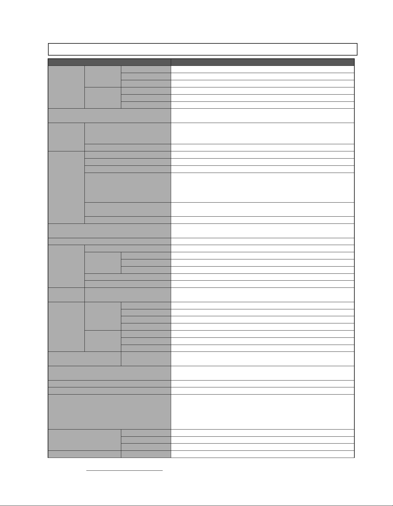
Specifications
Items Specifications
100 V
Main Circuit
Input Power
Supply
Control Circuit
Control Method
Feedback
Operating
Conditions
Compliant Standards
Configuration
Performance
I/O Signals Encoder Output Pulses
Communications
Display Power Charge
Analog Monitor
Protective Functions Overcurrent, Overvoltage, low voltage, overload, regeneration error
Utility Functions Alarm history, JOG operation, origin search, etc.
Regenerative Processing
Safety Functions
Option Card Function Feedback Serial encoder communications input for fully-closed loop control
*: Speed regulation is defined as follows:
Speed regulation =
The motor speed may change due to voltage variations or temperature variation. The ratio of speed changes to the rated speed represent speed regulation due to voltage and
temperature variations.
Rotary Servomotors
Linear Servomotors Serial converter or serial data
Surrounding/Storage Temperature
Ambient/Storage Humidity 90%RH or less (no condensation)
Vibration/Shock Resistance Vibration resistance: 4.9 m/s
Protection class/Pollution degree
Others
Elevation 1000 m or less
Speed Control Range
Speed
Regulation*
Torque Control Tolerance (Repeatability)
Soft Start Time Setting 0 to 10 s (can be set individually for acceleration and deceleration.)
RS-422A
Communications
USB
Communications
No-load motor speed − Total load motor speed
200 V
400 V
100 V
200 V
400 V
Load Regulation
Voltage Regulation
Temperature Regulation
Interface Digital operator, RS-422A port of personal computers etc.
1:N communications
Axis address setting Set by parameters
Function
Interface
1:N communications Compliant with USB1.1 standard
Function
Input /HWBB1, /HWBB2: Hard wire base block signal
Output EDM1: Status monitor (fixed output) of built-in safety circuit
Compliant Standards EN954 category 3 Stop category 0, IEC61508 SIL 2
Rated motor speed
Single-phase 100 to 1
Three-phase 200 to 230 VAC
Three-phase 380 to 480 VAC
Single-phase 100 to 115 VAC
Single-phase 200 to 230 VAC
±
24 VDC
For 100 V, for 200 V, for 400 V, single-phase or three-phase full-wave rectification
IGBT PWM control, sine-wave driven
Serial encoder: 13-bit (incremental encoder)
: 17-bit (incremental/absolute encoder)
: 20-bit (incremental/absolute encoder)
Surrounding temperature: 0 to
Protection class: IP 1X, pollution degree: 2
Do not use SERVOPACKs in the following locations:
·Locations subject to corrosive or flammable gasses
·Locations subject to exposure to water, oil, or chemicals
·Locations subject to dust, including iron dust, and salts
Do not use SERVOPACKs in the following locations:
·Locations subject to static electricity noise, strong electromagnetic/magnetic fields, radioactivity
UL 508C
EN50178, EN55011 class A group 1, EN61800-3, EN61800-5-1
Base-mounted (Rack-mounting available as an option for some models. 6 kW or more models are duct-ventilated.)
1:5000 (The lowest speed of the speed control range is the speed at which the servomotor will not stop with a rated torque load.)
0% to 100% load:
Rated voltage:
25
±
Phase A, phase B, phase C: line driver output
The number of dividing pulse: Any setting ratio is available.
RS-422A port: N
Status display, parameter settings, adjustment functions, utility functions
Personal computers (application: engineering tool SigmaWin
Status display, parameter settings, adjustment functions, utility functions
CHARGE for main circuit power supply input confirmation
One LED (orange)
Analog monitor connector built in for monitoring speed, torque and other reference signals.
Number of points: 2
100 VAC model: External regenerative resistor (optional)
200 VAC SGDV-R70A, -R90A, -1R6A, -2R8A: External regenerative resistor (optional)
200 VAC SGDV-470A, -550A, -590A, -780A: External regenerative resistor unit (optional)
200 VAC models other than shown above: Built-in regenerative resistor
400 VAC SGDV-210D, -260D, -280D, -370D: External regenerative resistor unit (optional)
400 VAC models other than shown above: Built-in regenerative resistor
15%
±
±
10% : 0% (at rated speed)
±
25˚C : ±0.1% max. (at rated speed)
1%
=
15 max. available
× 100%
+
15 VAC
10% to −15% 50/60 Hz
+
10% to −15% 50/60 Hz
+
10% to −15% 50/60 Hz
+
10% to −15% 50/60 Hz
+
10% to −15% 50/60 Hz
+
55˚C, storage temperature: −20 to +85˚C
2
, Shock resistance: 19.8 m/s
0.01% max. (at rated speed)
2
+
)
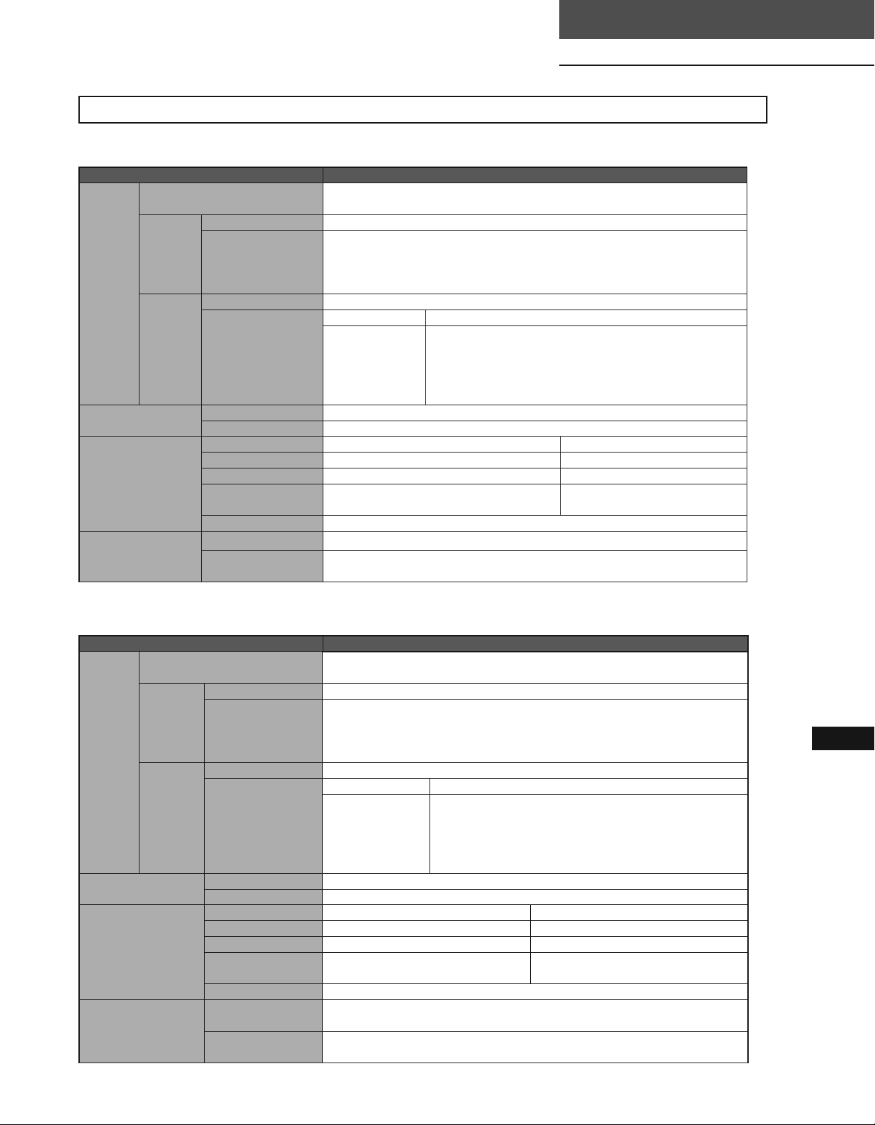
Specifications
Specifications
1Rotary Servomotors
Items Specifications
Encoder Output Pulses
Sequence
Input
I/O Signal
Sequence
Output
Panel Operator
MECHATROLINK
Communications
Command Method
Number of Channels
Function
Fixed Output Servo alarm (ALM)
Output Signals which can
be allocated
Display 7-segment 1-digit LED (red)
Switch Rotary switch: 16 positions, DIP switch: 4 poles
Communications Protocol MECHATROLINK-II MECHATROLINK-I
Transmission Speed 10 Mbps 4 Mbps
Transmission Cycle
Number of Words for
Link Transmission
Station Address 41H to 5FH (max. number of slaves: 30)
Performance Position control, speed control, and torque control through MECHATROLINK communications
Command Input
Phase A, phase B, phase C: line driver output
The number of dividing pulse: Any setting ratio is available.
7 channels
Signal allocations and positive/negative logics can be modified.
Homing deceleration switch signal (/DEC), external latch signal (/EXT1 to 3), forward run prohibited
(P-OT), reverse run prohibited (N-OT),
forward current limit (/P-CL), reverse current limit (/N-CL)
Number of Channels
Function
250
μ
s, 0.5 to 4.0 ms (multiple of 0.5 ms)
Can be switched between
17-bytes /station and 32-bytes / station.
MECHATROLINK commands (for sequence, motion, data setting/reference, monitor, adjustment, and
other commands.)
MECHATROLINK-II Type SERVOPACKs
SGDV-¡¡¡¡11/15
3 channels
Signal allocations and positive/negative logics can be modified.
Positioning completion (/COIN), speed coincidence detection
(/V-CMP), servomotor rotation detection (/TGON), servo ready (/S-RDY), torque limit
detection (/CLT), speed limit detection
(/VLT), brake interlock (/BK), warning (/WARN), NEAR (/NEAR)
2 ms
17-bytes /station
1Linear Servomotors
Items Specifications
Encoder Output Pulses
Sequence
Input
I/O Signal
Sequence
Output
Panel Operator
MECHATROLINK
Communications
Command Method
Number of Channels
Function
Fixed Output Servo alarm (ALM)
Output Signals which can
be allocated
Display 7-segment 1-digit LED (red)
Switch Rotary switch: 16 positions, piano switch: 4 poles
Communications Protocol MECHATROLINK-II MECHATROLINK-I
Transmission Speed 10 Mbps 4 Mbps
Transmission Cycle
Number of Words for
Link Transmission
Station Address 41H to 5FH (max. number of slaves: 30)
Performance
Command Input
Phase A, phase B, phase C: line driver output
The number of dividing pulse: Any setting ratio is available.
7 channels
Signal allocations and positive/negative logics can be modified.
Homing deceleration switch signal (/DEC), external latch signal (/EXT1 to 3), forward run prohibited
(P-OT), reverse run prohibited (N-OT),
forward current limit (/P-CL), reverse current limit (/N-CL)
Number of Channels 3 channels
Function
μ
s, 0.5 to 4.0 ms (multiple of 0.5 ms)
250
Can be switched between
17-bytes /station and 32-bytes / station.
Position control, speed control, and force control through
MECHATROLINK-II communications
MECHATROLINK commands and MECHATROLINK-II commands
(for sequence, motion, data setting/reference, monitor, adjustment, and other commands.)
Signal allocations and positive/negative logics can be modified. Positioning
completion (/COIN), speed coincidence detection
(/V-CMP), servomotor movement detection (/TGON),
servo ready (/S-RDY), force limit detection (/CLT),
speed limit detection (/VLT), brake interlock (/BK),
warning (/WARN), NEAR (/NEAR)
2 ms
17-bytes /station
MECHATROLINK-II Type SERVOPACKs
260

Power Supply Capacities and Power Losses
The following table shows SERVOPACK's power supply capacities and power losses at the rated output.
The following table shows SERVOPACK's power supply capacities and power losses at the rated output.
Regenerative
Power Loss
Main Circuit
Power
Supply
Signal-phase
100 V
Applicable
Servomotor
Max.
Capacity
kW
0.05 R70F
SERVOPACK
Model
SGDV-
Power Supply
Capacity
kVA
Output Current
A
0.2 0.66 5.4
Main Circuit
Power Loss
W
0.1 R90F 0.3 0.91 7.8 24.8
0.2 2R1F 0.7 2.1 14.4 31.4
0.4 2R8F 1.4 2.8 25.6 42.6
0.05 R70A 0.2 0.66 5.2
0.1 R90A 0.3 0.91 7.4 24.4
Single-phase
200 V
0.2 1R6A 0.7 1.6 13.7 30.7
0.4 2R8A 1.2 2.8 24.9 41.9
0.75 5R5A 1.9 5.5 52.7 8 77.7
1.5 120A 4 11.6 68.2 10 22 100.2
0.05 R70A 0.2 0.66 5.1
0.1 R90A 0.3 0.91 7.3 24.3
0.2 1R6A 0.6 1.6 13.5 30.5
0.4 2R8A 1 2.8 24.0 41.0
0.5 3R8A 1.4 3.8 20.1
0.75 5R5A 1.6 5.5 43.8 68.8
Three-phase
200 V
1.0 7R6A 2.3 7.6 53.6 78.6
1.5 120A 3.2 11.6 65.8
2.0 180A 4 18.5 111.9
3.0 200A 5.9 19.6 113.8 161.4
5.0 330A 7.5 32.9 263.7 36 27 326.7
6.0 470A 10.7 46.9 279.4 (180)
7.5 550A 14.6 54.7 357.8
11 590A 21.7 58.6 431.7
15 780A 29.6 78 599.0 647.0
0.5 1R9D 1.1 1.9 24.6
1.0 3R5D 2.3 3.5 46.1 81.1
1.5 5R4D 3.5 5.4 71.3 106.3
2.0 8R4D 4.5 8.4 77.9
Three-phase
400 V
3.0 120D 7.1 11.9 108.7 161.7
5.0 170D 11.7 16.5 161.1 36 24 221.1
6.0 210D 12.4 20.8 172.7
7.5 260D 14.4 25.7 218.6 245.6
11 280D 21.9 28.1 294.6
15 370D 30.6 37.2 403.8 433.8
*1: For the optional JUSP-RA04-E regenerative resistor unit.
*2: For the optional JUSP-RA05-E regenerative resistor unit.
*3: For the optional JUSP-RA18-E regenerative resistor unit.
*4: For the optional JUSP-RA19-E regenerative resistor unit.
Notes:
1 SGDV-R70F, -R90F, -2R1F, -2R8F, -R70A, -R90A, -1R6A, and -2R8A SERVOPACKs do not have built-in regenerative resistors.
If the regenerative energy exceeds the specified value, connect an external regenerative resistor (optional).
2 SGDV-470A, -550A, -590A, -780A, -210D, -260D, -280D, -370D SERVOPACKs do not have built-in regenerative resistors.
Be sure to connect a regenerative resistor unit (optional) or an external regenerative resistor (optional). For selection details, refer to page 293.
3 Regenerative resistor power losses are allowable losses. Take the following action if this value is exceeded.
· Remove the lead or short bar that is short-circuiting the SERVOPACK main circuit terminal B2 and B3.
(SGDV-3R8A, -5R5A, -7R6A, -120A, -180A, -200A, -330A, or 400-V class SERVOPACKs.)
· Install an external regenerative resistor (optional). For selection details, refer to page 293.
Resistor
Control Circuit
Power Loss
W
W
—17
—
17
—
17
8
10
16
*1
22
33
*2
(350)
48
14 21
28 25
*3
(180)
(350)
*4
27
30
Total Power
Loss
W
22.4
22.2
22.1
45.1
97.8
149.9
312.4
390.8
479.7
59.6
130.9
199.7
324.6
261
 Loading...