

Page 1

Linear Series SGL□□/SGDH
USER'S MANUAL
SGLGW/SGLFW/SGLTW Linear Servomotors
SGDH SERVOPACK
YASKAWA
YASKAWA
YA S K A WA
MANUAL NO. YEA-SIA-S800-39.21
Page 2

Copyright © 2004 YASKAWA ELECTRIC AMERICA
All rights reserved. No part of this publication may be reproduced, stored in a retrieval system,
or transmitted, in any form, or by any means, mechanical, electronic, photocopying, recording,
or otherwise, without the prior written permission of Yaskawa. No patent liability is assumed
with respect to the use of the information contained herein. Moreover, because Yaskawa is constantly striving to improve its high-quality products, the information contained in this manual is
subject to change without notice. Every precaution has been taken in the preparation of this
manual. Nevertheless, Yaskawa assumes no responsibility for errors or omissions. Neither is
any liability assumed for damages resulting from the use of the information contained in this
publication.
Page 3

About this Manual
Intended Audience
This manual is intended for the following users.
•
Those selecting Σ-II Series servodrives or peripheral devices for Σ-II Series servodrives.
•
Those wanting to know about the ratings and characteristics of Σ-II Series servodrives.
•
•
•
•
Description of Technical Terms
The terms in this manual are defined as follows:
• Servomotor or motor =
• SERVOPACK = Σ-II Series SGDH amplifier.
• Servodrive = A set including a servomotor and servo amplifier.
• Servo System = A servo control system that includes the combination of a servodrive with a host
• Parameter number = Numbers that the user inputs toward the SERVOPACK.
Indication of Reverse Signals
In this manual, the names of reverse signals (ones that are valid when low) are written with a forward slash (/)
before the signal name, as shown in the following example:
• S-ON
• P-CON
designing Σ-II Series servodrive systems.
Those
Those installing or wiring Σ-II Series servodrives.
Those performing trial operation or adjustments of Σ-II Series servodrives.
Those maintaining or inspecting Σ-II Series servodrives.
Linear Σ Series SGLGW, SGLFW and SGLTW linear servomotor
computer and peripheral devices.
/S-ON
=
/P-CON
=
iii
Page 4

Safety Information
The following conventions are used to indicate precautions in this manual. Failure to heed precautions provided
in this manual can result in serious or possibly even fatal injury or damage to the products or to related equipment
and systems.
WARNING
CAUTION
PROHIBITED
MANDATORY
Indicates precautions that, if not heeded, could possibly result in loss of life or serious
injury.
Indicates precautions that, if not heeded, could result in relatively serious or minor
injury, damage to the product, or faulty operation.
In some situations, the precautions indicated could have serious consequences if not heeded.
Indicates prohibited actions that must not be performed. For example, this symbol
would be used as follows to indicate that fire is prohibited: .
Indicates compulsory actions that must be performed. For example, this symbol would
be used as follows to indicate that grounding is compulsory: .
The warning symbols for ISO and JIS standards are different, as shown below.
ISO JIS
The ISO symbol is used in this manual.
Both of these symbols appear on warning labels on Yaskawa products. Please abide by these warning labels
regardless of which symbol is used.
iii
Page 5

Notes for Safe Operation
Read this manual thoroughly before checking products on delivery, storage and transportation, installation,
wiring, operation and inspection, and disposal of the AC servodrive.
WARNING
• If you have a pacemaker or any other electronic medical device, do not go near the magnetic
way of the linear servomotor.
Failure to observe this warning may result in the malfunction of the medical device.
• Be sure to use nonmagnetic tools when installing or working close to the linear servomotor.
(Example: a beryllium-copper alloy hexagonal wrench set, made by NGK Insulators, Ltd.)
• If starting an operation with the linear servomotor in a machine, set the linear servomotor to
always allow emergency stops.
Failure to observe this warning may result in injury.
• Never touch the linear servomotor or machinery during operation.
Failure to observe this warning may result in injury.
• Before wiring, install the SERVOPACK and the linear servomotor.
Failure to observe this warning may result in electric shock.
• Do not operate switches with wet hands.
Failure to observe this warning may result in electric shock.
• Never touch the inside of the SERVOPACKs.
Failure to observe this warning may result in electric shock.
• Do not touch terminals for five minutes after the power is turned OFF.
Residual voltage may cause electric shock.
• Do not touch terminals for five minutes after voltage resistance test.
Residual voltage may cause electric shock.
• Make sure that the main circuit power cable, the control power cable, and the linear
servomotor main circuit cable are wired correctly.
Failure to observe this warning may result in damage to the SERVOPACK.
• Follow the procedures and instructions for trial operation precisely as described in this manual.
Malfunctions that occur after the servomotor is connected to the equipment not only damage the
equipment, but may also cause an accident resulting in death or injury.
• The SGDH SERVOPACK supports both AC and DC power. If DC power is supplied to the
SERVOPACK without setting Pn001=n1 (DC power input), the internal components of
the SERVOPACK will burn and may result in fire or serious damage.
Before using a DC power supply, be sure to check the parameter Pn001 setting.
• Do not remove the front cover, cables, connectors, or optional items while the power is ON.
Failure to observe this warning may result in electric shock.
• Do not damage, press, exert excessive force or place heavy objects on the cables.
Failure to observe this warning may result in electric shock, stopping operation of the product, or
burning.
iv
Page 6
WARNING
• Provide an appropriate stopping device on the machine side to ensure safety. A holding brake for a
servomotor with brake is not a stopping device for ensuring safety.
Failure to observe this warning may result in injury.
• Do not come close to the machine immediately after resetting momentary power loss to avoid an
unexpected restart. Take appropriate measures to ensure safety against an unexpected restart.
Failure to observe this warning may result in injury.
• Connect the ground terminal to electrical codes (ground resistance: 100 Ω or less).
Improper grounding may result in electric shock or fire.
• Installation, disassembly, or repair must be performed only by authorized personnel.
Failure to observe this warning may result in electric shock or injury.
• Do not modify the product.
Failure to observe this warning may result in injury or damage to the product.
Checking on Delivery
CAUTION
• Always use the linear servomotor and SERVOPACK in one of the specified combinations.
Failure to observe this caution may result in fire or malfunction.
Storage and Transportation
CAUTION
• Do not store or install the product in the following places.
• Locations subject to direct sunlight.
• Locations subject to temperatures outside the range specified in the storage or installation temperature conditions.
• Locations subject to humidity outside the range specified in the storage or installation humidity conditions.
• Locations subject to condensation as the result of extreme changes in temperature.
• Locations subject to corrosive or flammable gases.
• Locations subject to dust, salts, or iron dust.
• Locations subject to exposure to water, oil, or chemicals.
• Locations subject to shock or vibration.
Failure to observe this caution may result in fire, electric shock, or damage to the product.
• Do not carry the linear servomotor by its cables.
Failure to observe this caution may result in injury or malfunction.
• Do not place any load exceeding the limit specified on the packing box.
Failure to observe this caution may result in injury or malfunction.
v
Page 7

Installation
CAUTION
• When unpacking and installing magnetic way, check that no metal fragments or magnetized objects near
the stator because they may be affected by the magnetic attraction of the magnetic way.
Failure to observe this caution may result in injury or damage to the magnetic way's magnets.
• Do not use the magnetic way near metal or other magnetized objects.
Failure to observe this caution may result in injury.
• Do not place clocks, magnetic cards, floppy disks, or measuring instruments close to the magnetic way.
Failure to observe this caution may result in malfunction or damage to these items by the magnetic force.
• Securely mount the linear servomotor on to the machine.
If the linear servomotor is not mounted securely, it may loosen during operation.
• Do not carry the magnetic way by its antimagnetic cover.
Failure to observe this caution may result in injury by the cover’s edge or the shape of the cover may become distorted.
Cover
Magnetic way
• Install SERVOPACKs, linear servomotors, and regenerative resistors on nonflammable objects.
Mounting directly onto or near flammable objects may result in fire.
• Never use the products in an environment subject to water, corrosive gases, inflammable gases, or
combustibles.
Failure to observe this caution may result in electric shock or fire.
• Do not step on or place a heavy object on the product.
Failure to observe this caution may result in injury.
• Do not cover the inlet or outlet parts and prevent any foreign objects from entering the product.
Failure to observe this caution may cause internal elements to deteriorate resulting in malfunction or fire.
• Be sure to install the product in the correct direction.
Failure to observe this caution may result in malfunction.
• Provide the specified clearances between the SERVOPACK and the control panel or with other devices.
Failure to observe this caution may result in fire or malfunction.
• Do not apply any strong impact.
Failure to observe this caution may result in malfunction.
vi
Page 8

Wiring
CAUTION
• Securely tighten the cable connector screws and securing mechanism.
If the connector screws and securing mechanism are not secure, they may loosen during operation.
• Use power lines and cables with a radius, heat resistance, and flexibility suitable for the system.
• If the SERVOPACK malfunctions, turn OFF the main circuit’s power supply of the SERVOPACK.
The continuous flow of a large current may cause fire.
• Use a noise filter to minimize the effects of electromagnetic damage.
Failure to observe this caution may result in electromagnetic damage to electronic devices used near the
SERVOPACK.
• Do not connect a three-phase power supply to the U, V, or W output terminals.
Failure to observe this caution may result in injury or fire.
• Securely connect the power supply terminals and motor output terminals.
Failure to observe this caution may result in fire.
• Do not bundle or run power and signal lines together in the same duct. Keep power and signal lines
separated by at least 30 cm (11.81 in).
Failure to observe this caution may result in malfunction.
• Use shielded twisted-pair wire or shielded multi-core twisted-pair wire for the signal lines and feedback lines
of the serial converter unit (SC).
The maximum wiring length is 3 m for the reference input line and 20 m for the SC feedback line.
• Do not touch the power terminals for five minutes after turning power OFF because high voltage may still
remain in the SERVOPACK.
Make sure the charge indicator is turned OFF first before starting an inspection.
• Avoid frequently turning power ON and OFF. Do not turn power ON or OFF more than once per minute.
Since the SERVOPACK has a capacitor in the power supply, a high charging current flows for 0.2 seconds when
power is turned ON. Frequently turning power ON and OFF causes main power devices such as capacitors and fuses
to deteriorate, resulting in unexpected problems.
• Observe the following precautions when wiring main circuit terminal blocks.
• Remove the terminal block from the SERVOPACK prior to wiring.
• Insert only one wire per terminal on the terminal block.
• Make sure that the core wire is not electrically shorted to adjacent core wires.
• Do not connect the SERVOPACK for 100 V and 200 V directly to a voltage of 400 V.
The SERVOPACK will be destroyed.
• Be sure to wire correctly and securely.
Failure to observe this caution may result in motor overrun, injury, or malfunction.
• Always use the specified power supply voltage.
An incorrect voltage may result in burning.
• Make sure that the polarity is correct.
Incorrect polarity may cause ruptures or damage.
• Take appropriate measures to ensure that the input power supply is supplied within the specified voltage
fluctuation range. Be particularly careful in places where the power supply is unstable.
An incorrect power supply may result in damage to the product.
vii
Page 9

CAUTION
• Install external breakers or other safety devices against short-circuiting in external wiring.
Failure to observe this caution may result in fire.
• Take appropriate and sufficient countermeasures for each when installing systems in the following
locations.
• Locations subject to static electricity or other forms of noise.
• Locations subject to strong electromagnetic fields and magnetic fields.
• Locations subject to possible exposure to radioactivity.
• Locations close to power supplies including power supply lines.
Failure to observe this caution may result in damage to the product.
Operation
CAUTION
• Do not stand within the machine's range of motion during operation.
Failure to observe this caution may result in injury.
• Before operation, install a limit switch or stopper on the end of the slider to prevent unexpected movement.
Failure to observe this caution may result in injury.
• Before starting operation with a machine connected, change the settings to match the parameters of the
machine.
Starting operation without matching the proper settings may cause the machine to run out of control or malfunction.
• Forward run prohibited (P-OT) and reverse run prohibited (N-OT) signals are not effective during zero point
search mode using parameter Fn003.
• If using the linear servomotor on a vertical axis, install a safety device such as a counterbalance so that the
workpiece does not fall if an alarm or overtravel occurs.
The workpiece may fall during overtraveling.
• When not using the normal autotuning, set to the correct mass ratio.
Setting to an incorrect moment of inertia ratio may cause vibration.
• Do not touch the SERVOPACK heatsinks, regenerative resistor, or servomotor while power is ON or soon
after the power is turned OFF.
Failure to observe this caution may result in burns due to high temperatures.
• Do not make any extreme adjustments or setting changes of parameters.
Failure to observe this caution may result in injury due to unstable operation.
• When an alarm occurs, remove the cause, reset the alarm after confirming safety, and then resume
operation.
Failure to observe this caution may result in injury.
viii
Page 10

Maintenance and Inspection
CAUTION
• When replacing the SERVOPACK, transfer the previous SERVOPACK parameters to the new
SERVOPACK before resuming operation.
Failure to observe this caution may result in damage to the product.
• Do not attempt to change wiring while the power is ON.
Failure to observe this caution may result in electric shock or injury.
• Do not disassemble the linear servomotor.
Failure to observe this caution may result in electric shock or injury.
Disposal
CAUTION
• When disposing of the products, treat them as ordinary industrial waste.
General Precautions
Note the following to ensure safe application.
• The drawings presented in this manual are sometimes shown without covers or protective guards. Always replace
the cover or protective guard as specified first, and then operate the products in accordance with the manual.
• The drawings presented in this manual are typical examples and may not match the product you received.
• This manual is subject to change due to product improvement, specification modification, and manual
improvement. When this manual is revised, the manual code is updated and the new manual is published as a next
edition.
• If the manual must be ordered due to loss or damage, inform your nearest Yaskawa representative or one of the
offices listed on the back of this manual.
• Yaskawa will not take responsibility for the results of unauthorized modifications of this product. Yaskawa shall
not be liable for any damages or troubles resulting from unauthorized modification.
ix
Page 11

CONTENTS
About this Manual- - - - - - - - - - - - - - - - - - - - - - - - - - - - - - - - - - - - - - - iii
Related Manuals - - - - - - - - - - - - - - - - - - - - - - - - - - - - - - - - - - - - - - - v
Safety Information - - - - - - - - - - - - - - - - - - - - - - - - - - - - - - - - - - - - - -vi
Notes for Safe Operation- - - - - - - - - - - - - - - - - - - - - - - - - - - - - - - - - vii
1 Outline
1.1 Checking Products - - - - - - - - - - - - - - - - - - - - - - - - - - - - - - 1-2
1.1.1 Check Items- - - - - - - - - - - - - - - - - - - - - - - - - - - - - - - - - - - - - - - - - -1-2
1.1.2 Linear Servomotors - - - - - - - - - - - - - - - - - - - - - - - - - - - - - - - - - - - -1-2
1.1.3 SERVOPACKs - - - - - - - - - - - - - - - - - - - - - - - - - - - - - - - - - - - - - - - -1-3
1.1.4 Serial Converter Units - - - - - - - - - - - - - - - - - - - - - - - - - - - - - - - - - -1-4
1.2 Product Part Names - - - - - - - - - - - - - - - - - - - - - - - - - - - - - 1-5
1.2.1 Linear Servomotors - - - - - - - - - - - - - - - - - - - - - - - - - - - - - - - - - - - -1-5
1.2.2 SERVOPACKs - - - - - - - - - - - - - - - - - - - - - - - - - - - - - - - - - - - - - - - -1-6
1.3 Examples of Servo System Configurations - - - - - - - - - - - - - 1-8
1.3.1 Single-phase, 200 V Main Circuit - - - - - - - - - - - - - - - - - - - - - - - - - - -1-8
1.3.2 Three-phase, 200 V Main Circuit - - - - - - - - - - - - - - - - - - - - - - - - - - -1-9
1.3.3 Three-phase, 400 V Main Circuit - - - - - - - - - - - - - - - - - - - - - - - - - -1-10
1.4 Applicable Standards - - - - - - - - - - - - - - - - - - - - - - - - - - - 1-11
1.4.1 North American Safety Standards (UL, CSA)- - - - - - - - - - - - - - - - - - 1-11
1.4.2 CE Marking - - - - - - - - - - - - - - - - - - - - - - - - - - - - - - - - - - - - - - - - - 1-11
2 Selections
2.1 Linear Servomotor Model Designation - - - - - - - - - - - - - - - - 2-2
2.1.1 Coil Assembly - - - - - - - - - - - - - - - - - - - - - - - - - - - - - - - - - - - - - - -2-2
2.1.2 Magnetic Way - - - - - - - - - - - - - - - - - - - - - - - - - - - - - - - - - - - - - - - -2-2
2.2 SERVOPACK Model Designation- - - - - - - - - - - - - - - - - - - - 2-3
2.3 Σ-II Series SERVOPACKs and Applicable Linear
Servomotors
2.4 Serial Converter Units Models - - - - - - - - - - - - - - - - - - - - - 2-6
2.5 Selecting Cables - - - - - - - - - - - - - - - - - - - - - - - - - - - - - - - 2-7
2.6 Selecting Peripheral Devices- - - - - - - - - - - - - - - - - - - - - - - 2-9
2.6.1 Special Options - - - - - - - - - - - - - - - - - - - - - - - - - - - - - - - - - - - - - - -2-9
2.6.2 Molded-case Circuit Breaker and Fuse Capacity - - - - - - - - - - - - - - - 2-11
2.6.3 Noise Filters, Magnetic Contactors, Surge Suppressors
and DC Reactors - - - - - - - - - - - - - - - - - - - - - - - - - - - - - - - - - - - - -2-12
2.6.4 Regenerative Resistors - - - - - - - - - - - - - - - - - - - - - - - - - - - - - - - - - 2-13
2.6.5 Linear Scales - - - - - - - - - - - - - - - - - - - - - - - - - - - - - - - - - - - - - - -2-14
- - - - - - - - - - - - - - - - - - - - - - - - - - - - - - - - - 2-4
x
Page 12

3 Digital Operator/Panel Operator
3.1 Functions on Digital Operator/Panel Operator - - - - - - - - - - - 3-2
3.1.1 Connecting the Digital Operator - - - - - - - - - - - - - - - - - - - - - - - - - - -3-2
3.1.2 Key Names and Functions - - - - - - - - - - - - - - - - - - - - - - - - - - - - - - -3-3
3.1.3 Basic Mode Selection and Operation - - - - - - - - - - - - - - - - - - - - - - - -3-4
3.1.4 Status Display - - - - - - - - - - - - - - - - - - - - - - - - - - - - - - - - - - - - - - - -3-6
3.2 Operation in Utility Function Mode (Fn) - - - - - - - - - - - 3-8
3.2.1 List of Utility Function Modes - - - - - - - - - - - - - - - - - - - - - - - - - - - - - -3-8
3.2.2 Alarm Traceback Data Display (Fn000)- - - - - - - - - - - - - - - - - - - - - - -3-9
3.2.3 JOG Mode Operation (Fn002) - - - - - - - - - - - - - - - - - - - - - - - - - - - -3-10
3.2.4 Zero-point Search Mode (Fn003) - - - - - - - - - - - - - - - - - - - - - - - - - - 3-11
3
.2.5 Parameter Settings Initialization (Fn005)- - - - - - - - - - - - - - - - - - - - -3-12
3.2.6 Alarm Traceback Data Clear (Fn006) - - - - - - - - - - - - - - - - - - - - - - -3-13
3.2.7 Automatic Offset-adjustment of Motor Current Detection Signal
(Fn00E)- - - - - - - - - - - - - - - - - - - - - - - - - - - - - - - - - - - - - - - - - - - -3-14
3.2.8 Manual Offset-adjustment of Motor Current Detection Signal
(Fn00F) - - - - - - - - - - - - - - - - - - - - - - - - - - - - - - - - - - - - - - - - - - - -3-15
3.2.9 Password Setting (Protects Parameters from Being Changed)
(Fn010) - - - - - - - - - - - - - - - - - - - - - - - - - - - - - - - - - - - - - - - - - - - -3-16
3.2.10 Motor Models Display (Fn011) - - - - - - - - - - - - - - - - - - - - - - - - - - -3-17
3.2.11 Software Version Display (Fn012)- - - - - - - - - - - - - - - - - - - - - - - - -3-18
3.2.12 Application Module Detection Results Clear (Fn014) - - - - - - - - - - -3-19
3.3 Operation in Parameter Setting Mode (Pn)- - - - - - - - 3-20
3.3.1 Setting Parameters- - - - - - - - - - - - - - - - - - - - - - - - - - - - - - - - - - - -3-20
3.3.2 Input Circuit Signal Allocation - - - - - - - - - - - - - - - - - - - - - - - - - - - -3-24
3.3.3 Output Circuit Signal Allocation - - - - - - - - - - - - - - - - - - - - - - - - - - - 3-28
3.4 Operation in Monitor Mode (Un) - - - - - - - - - - - - - - - 3-30
3.4.1 List of Monitor Modes- - - - - - - - - - - - - - - - - - - - - - - - - - - - - - - - - - 3-30
3.4.2 Sequence I/O Signal Monitor Display- - - - - - - - - - - - - - - - - - - - - - - 3-31
3.4.3 Operation in Monitor Mode - - - - - - - - - - - - - - - - - - - - - - - - - - - - - - 3-32
3.4.4 Monitor Display of Reference Pulse Counter
and Feedback Pulse Counter - - - - - - - - - - - - - - - - - - - - - - - - - - - - 3-33
3.4.5 Allowable Maximum Motor Speed for Dividing Ratio Monitor
(For the software version 32 or later) - - - - - - - - - - - - - - - - - - - - - - - 3-34
3.4.6 Hall Sensor Signal Monitor
(For the software version 32 or later) - - - - - - - - - - - - - - - - - - - - - - - 3-34
4 Operation
4.1 Trial Operation - - - - - - - - - - - - - - - - - - - - - - - - - - - - - - - - - 4-4
4.2 Trial Operation Using SERVOPACK Internal References - - - 4-6
4.2.1 SERVOPACK Setup Procedure- - - - - - - - - - - - - - - - - - - - - - - - - - - - 4-6
4.2.2 Setup Procedure Using Linear Servomotors with Hall Sensors- - - - - - 4-6
4.2.3 Setup Procedure Using Linear Servomotors without Hall Sensors - - 4-12
xi
xvi
Page 13

4.3 Trial Operation for Linear Servomotor without Load
from Host Reference - - - - - - - -
4.3.1 Servo ON Command from the Host - - - - - - - - - - - - - - - - - - - - - - - - 4-22
4.3.2 Operating Procedure in Speed Control Mode (Pn000 = n.0) - - 4-24
4.3.3 Operating Procedure in Position Control Mode (Pn000 = n.1) - 4-26
- - - - - - - - - - - - - - - - - - - 4-22
Trial O
4.4
to
.5 Control Mode Selection- - - - - - - - - - - - - - - - - - - - - - - - - - 4-29
4
.6 Setting Common Basic Functions - - - - - - - - - - - - - - - - - - 4-30
4
4.6.1 Setting the Servo ON Signal - - - - - - - - - - - - - - - - - - - - - - - - - - - - - 4-30
4.6.2 Switching the Linear Servomotor Movement Direction- - - - - - - - - - - 4-31
4.6.3 Setting the Overtravel Limit Function - - - - - - - - - - - - - - - - - - - - - - - 4-32
4.6.4 Selecting the Stop
4.6.5 Instantaneous Power Loss Settings- - - - - - - - - - - - - - - - - - - - - - - - 4-35
4.6.6 Motor Maximum Speed (For the software version 32 or later)- - - - - - 4-35
peration with the Linear Servomotor Connected
the Machine
- - - - -
- - - - - - - - - - - - - - - - - - - - - - - - - - - 4-28
ping Method After Servo OFF - - - - - - - - - - - - - - - 4-34
4.7 Operating Using Speed Control with Analog Reference - - - 4-36
4.7.1 Setting Parameters - - - - - - - - - - - - - - - - - - - - - - - - - - - - - - - - - - - 4-36
4.7.2 Setting Input Signals - - - - - - - - - - - - - - - - - - - - - - - - - - - - - - - - - - 4-37
4.7.3 Adjusting Offset - - - - - - - - - - - - - - - - - - - - - - - - - - - - - - - - - - - - - - 4-38
4
.7.4 Soft Start- - - - - - - - - - - - - - - - - - - - - - - - - - - - - - - - - - - - - - - - - - - 4-41
4.7.5 Speed Reference Filter- - - - - - - - - - - - - - - - - - - - - - - - - - - - - - - - - 4-41
4.7.6 Using the Zero Clamp Function- - - - - - - - - - - - - - - - - - - - - - - - - - - 4-41
4.7.7 Encoder Signal Output - - - - - - - - - - - - - - - - - - - - - - - - - - - - - - - - - 4-43
4.7.8 Speed Coincidence Output - - - - - - - - - - - - - - - - - - - - - - - - - - - - - - 4-45
4.8 Operating Using Position Control- - - - - - - - - - - - - - - - - - - 4-46
4.8.1 Setting Parameters - - - - - - - - - - - - - - - - - - - - - - - - - - - - - - - - - - - 4-46
4.8.2 Setting the Electronic Gear - - - - - - - - - - - - - - - - - - - - - - - - - - - - - - 4-48
4.8.3 Position Reference - - - - - - - - - - - - - - - - - - - - - - - - - - - - - - - - - - - -4-51
4.8.4 Smoothing - - - - - - - - - - - - - - - - - - - - - - - - - - - - - - - - - - - - - - - - - -4-55
4.8.5 Positioning Completed Output Signal - - - - - - - - - - - - - - - - - - - - - - -4-56
4.8.6 Positioning Near Signal- - - - - - - - - - - - - - - - - - - - - - - - - - - - - - - - -4-57
4.8.7 Reference Pulse Inhibit Function (INHIBIT)- - - - - - - - - - - - - - - - - - -4-58
4.9 Operating Using Force Control - - - - - - - - - - - - - - - - - - - - 4-59
4.9.1 Setting Parameters- - - - - - - - - - - - - - - - - - - - - - - - - - - - - - - - - - - -4-59
4.9.2 Force Reference Input - - - - - - - - - - - - - - - - - - - - - - - - - - - - - - - - -4-59
4.9.3 Adjusting the Force Reference Offset - - - - - - - - - - - - - - - - - - - - - - -4-60
4.9.4 Limiting Linear Servomotor Speed during Force Control- - - - - - - - - -4-62
4.10 Operating Using Speed Control
with
an Internally Set Speed - - - - - - - - - - - - - - - - - - - - - 4-64
4.10.1 Setting Parameters - - - - - - - - - - - - - - - - - - - - - - - - - - - - - - - - - - -4-64
4.10.2 Input Signal Settings - - - - - - - - - - - - - - - - - - - - - - - - - - - - - - - - - -4-65
4.10.3 Operating Using an Internally Set Speed- - - - - - - - - - - - - - - - - - - -4-65
xv
xii
Page 14

4.11 Limiting Force- - - - - - - - - - - - - - - - - - - - - - - - - - - - - - - - 4-67
4.11.1 Internal Force Limit (Limiting Maximum Output Force) - - - - - - - - - -4-67
4.11.2 External Force Limit (Output Force Limiting by Input Signals) - - - - -4-68
4.11.3 Force Limiting Using an Analog Voltage Reference - - - - - - - - - - - -4-70
4.11.4 Force Limiting Using an External Force Limit
and Analog Voltage Reference - - - - - - - - - - - - - - - - - - - - - - - - - - -4-71
4.11.5 Checking Output Force Limiting during Operation - - - - - - - - - - - - -4-72
4.12 Control Mode Selection- - - - - - - - - - - - - - - - - - - - - - - - - 4-73
4.12.1 Setting Parameters - - - - - - - - - - - - - - - - - - - - - - - - - - - - - - - - - - -4-73
4.12.2 Switching the Control Mode - - - - - - - - - - - - - - - - - - - - - - - - - - - - -4-73
4.13 Other Output Signals - - - - - - - - - - - - - - - - - - - - - - - - - - 4-75
4.13.1 Servo Alarm Output (ALM) and Alarm Code Output
(ALO1, ALO2, ALO3) - - - - - - - - - - - - - - - - - - - - - - - - - - - - - - - - -4-75
4.13.2 Warning Output (/WARN)- - - - - - - - - - - - - - - - - - - - - - - - - - - - - - -4-76
4.13.3 Running Output Signal (/TGON)- - - - - - - - - - - - - - - - - - - - - - - - - -4-76
4.13.4 Servo Ready (/S-RDY) Output - - - - - - - - - - - - - - - - - - - - - - - - - - -4-77
5 Adjustments
5.1 Autotuning - - - - - - - - - - - - - - - - - - - - - - - - - - - - - - - - - - 5-2
5.1.1 Servo Gain Adjustment Methods - - - - - - - - - - - - - - - - - - - - - - - - -5-2
5.1.2 List of Servo Adjustment Functions- - - - - - - - - - - - - - - - - - - - - - - -5-3
5.2 Online Autotuning- - - - - - - - - - - - - - - - - - - - - - - - - - - - - 5-5
5.2.1 Online Autotuning - - - - - - - - - - - - - - - - - - - - - - - - - - - - - - - - - - - -5-5
5.2.2 Online Autotuning Procedure - - - - - - - - - - - - - - - - - - - - - - - - - - - -5-6
5.2.3 Selecting the Online Autotuning Execution Method - - - - - - - - - - - -5-7
5.2.4 Machine Rigidity Setting for Online Autotuning - - - - - - - - - - - - - - -5-8
5.2.5 Method for Changing the Machine Rigidity Setting - - - - - - - - - - - - -5-9
5.2.6 Saving the Results of Online Autotuning - - - - - - - - - - - - - - - - - - - 5-10
5.2.7 Procedure for Saving the Results of Online Autotuning- - - - - - - - - 5-11
5.3 Manual Tuning - - - - - - - - - - - - - - - - - - - - - - - - - - - - - - 5-12
5.3.1 Explanation of Servo Gain - - - - - - - - - - - - - - - - - - - - - - - - - - - - - 5-12
5.3.2 Servo Gain Manual Tuning - - - - - - - - - - - - - - - - - - - - - - - - - - - - 5-13
5.3.3 Position Loop Gain- - - - - - - - - - - - - - - - - - - - - - - - - - - - - - - - - - 5-13
5.3.4 Speed Loop Gain - - - - - - - - - - - - - - - - - - - - - - - - - - - - - - - - - - - 5-14
5.3.5 Speed Loop Integral Time Constant - - - - - - - - - - - - - - - - - - - - - - 5-14
5.4 Servo Gain Adjustment Functions - - - - - - - - - - - - - - - - 5-15
5.4.1 Feed-forward Reference- - - - - - - - - - - - - - - - - - - - - - - - - - - - - - 5-15
5.4.2 Force Feed-forward - - - - - - - - - - - - - - - - - - - - - - - - - - - - - - - - - 5-16
5.4.3 Speed Feed-forward- - - - - - - - - - - - - - - - - - - - - - - - - - - - - - - - - 5-17
5.4.4 Proportional Control Operation
(Proportional Operation Reference) - - - - - - - - - - - - - - - - - - - - - - 5-18
5.4.5 Using the Mode Switch (P/PI Switching)- - - - - - - - - - - - - - - - - - - 5-19
5.4.6 Setting the Speed Bias - - - - - - - - - - - - - - - - - - - - - - - - - - - - - - - 5-22
5.4.7 Speed Feedback Filter - - - - - - - - - - - - - - - - - - - - - - - - - - - - - - - 5-22
5.4.8 Speed Feedback Compensation - - - - - - - - - - - - - - - - - - - - - - - - 5-23
5.4.9 Switching Gain Settings - - - - - - - - - - - - - - - - - - - - - - - - - - - - - - 5-25
5.4.10 Force Reference Filter - - - - - - - - - - - - - - - - - - - - - - - - - - - - - - 5-26
5.5 Analog Monitor- - - - - - - - - - - - - - - - - - - - - - - - - - - - - - 5-29
xvixiii
Page 15

6 Inspection, Maintenance, and Troubleshooting
6.1 Troubleshooting - - - - - - - - - - - - - - - - - - - - - - - - - - - - - - 6-2
6.1.1 Alarm Display Table - - - - - - - - - - - - - - - - - - - - - - - - - - - - - - - - - - 6-2
6.1.2 Warning Display- - - - - - - - - - - - - - - - - - - - - - - - - - - - - - - - - - - - - 6-4
6.1.3 Alarm Display Table when the Application Module is Used - - - - - - - 6-5
6.1.4 Warning Display Table when the Application Module is Used - - - - - 6-6
6.1.5 Troubleshooting of Alarm and Warning- - - - - - - - - - - - - - - - - - - - - 6-7
6.1.6 Troubleshooting for Malfunction without Alarm Display- - - - - - - - - 6-17
6.2 Inspection and Maintenance - - - - - - - - - - - - - - - - - - - - 6-22
6.2.1 Linear Servomotor Inspection
6.2.2 SERVOPACK Inspection- - - - - - - - - - - - - - - - - - - - - - - - - - - - - - 6-22
6.2.3 SERVOPACK’s Parts Replacement Schedule- - - - - - - - - - - - - - - 6-23
- - - - - - - - - - - - - - - - - - - - - - - - - - 6-22
7 Appendix
7.1 Linear Servomotor Capacity Selection Examples- - - - - - - 7-2
7.2 Calculating the Required Capacity
of Regenerative Resistor
7.2.1 Simple Calculation - - - - - - - - - - - - - - - - - - - - - - - - - - - - - - - - - - - 7-4
7.2.2 Calculating the Regenerative Energy - - - - - - - - - - - - - - - - - - - - - - 7-6
s- - - - - - - - - - - - - - - - - - - - - - - 7-4
7.3 Connection to Host Controller - - - - - - - - - - - - - - - - - - - 7-13
73.1 Example of Connection to MP920 4-axes Analog Module
SVA-01 - - - - - - - - - - - - - - - - - - - - - - - - - - - - - - - - - - - - - - - - - - 7-13
7.3.2 Example of Connection to CP-9200SH Servo Controller Module
SVA (SERVOPACK in Speed Control Mode)- - - - - - - - - - - - - - - - 7-14
7.3.3 Example of Connection to MEMOCON GL120/130 Series
Motion Module MC20 - - - - - - - - - - - - - - - - - - - - - - - - - - - - - - - - 7-15
7.3.4 Example of Connection to MEMOCON GL60/70 Series
Positioning Module B2813 (SERVOPACK in Position Control Mode) 7-16
7.3.5 Example of Connection to OMRON’s Motion Control Unit- - - - - - - 7-17
7.3.6 Example of Connection to OMRON’s Position Control Unit - - - - - - 7-18
7.3.7 Example of Connection to OMRON’s Position Control Unit
00-NC221 (SERVOPACK in Speed Control Mode)- - - - - - - - - -7-19
C5
7.3.8 Example of Connection to OMRON’s Position Control Unit
C500-NC112 (SERVOPACK in Position Control Mode)- - - - - - - - -7-20
7.3.9 Example of Connection to Mitsubishi’s AD72 Positioning Unit
(SERVOPACK in Speed Control Mode)- - - - - - - - - - - - - - - - - - - -7-21
7.3.10 Example of Connection to Mitsubishi’s AD75 Positioning Unit
(SERVOPACK in Position Control Mode)- - - - - - - - - - - - - - - - - -7-22
7.4 List of Parameters - - - - - - - - - - - - - - - - - - - - - - - - - - - 7-23
7.4.1 Utility Functions List - - - - - - - - - - - - - - - - - - - - - - - - - - - - - - - - - 7-23
7.4.2 List of Parameters- - - - - - - - - - - - - - - - - - - - - - - - - - - - - - - - - - - 7-24
7.4.3 Monitor Modes - - - - - - - - - - - - - - - - - - - - - - - - - - - - - - - - - - - - - 7-40
7.5 Parameter Recording Table- - - - - - - - - - - - - - - - - - - - - 7-41
xiv
xvii
Page 16

1
Outline
1.1 Checking Products - - - - - - - - - - - - - - - - - - - - - - - - - - - - - - - - - - - - - - - - 1-2
1.1.1 Check Items - - - - - - - - - - - - - - - - - - - - - - - - - - - - - - - - - - - - - - - - - - - - - - - - - - - - - 1-2
1.1.2 Linear Servomotors - - - - - - - - - - - - - - - - - - - - - - - - - - - - - - - - - - - - - - - - - - - - - - - - 1-2
1.1.3 SERVOPACKs - - - - - - - - - - - - - - - - - - - - - - - - - - - - - - - - - - - - - - - - - - - - - - - - - - - 1-3
1.1.4 Serial Converter Units - - - - - - - - - - - - - - - - - - - - - - - - - - - - - - - - - - - - - - - - - - - - - - 1-4
1.2 Product Part Names - - - - - - - - - - - - - - - - - - - - - - - - - - - - - - - - - - - - - - - 1-5
1.2.1 Linear Servomotors - - - - - - - - - - - - - - - - - - - - - - - - - - - - - - - - - - - - - - - - - - - - - - - - 1-5
1.2.2 SERVOPACKs - - - - - - - - - - - - - - - - - - - - - - - - - - - - - - - - - - - - - - - - - - - - - - - - - - - 1-6
1.3 Examples of Servo System Configurations - - - - - - - - - - - - - - - - - - - - - - - 1-8
1.3.1 Single-phase, 200 V Main Circuit - - - - - - - - - - - - - - - - - - - - - - - - - - - - - - - - - - - - - - 1-8
1.3.2 Three-phase, 200 V Main Circuit - - - - - - - - - - - - - - - - - - - - - - - - - - - - - - - - - - - - - - - 1-9
1.3.3 Three-phase, 400 V Main Circuit - - - - - - - - - - - - - - - - - - - - - - - - - - - - - - - - - - - - - - 1-10
1
1.4 Applicable Standards - - - - - - - - - - - - - - - - - - - - - - - - - - - - - - - - - - - - - 1-11
1.4.1 North American Safety Standards (UL, CSA) - - - - - - - - - - - - - - - - - - - - - - - - - - - - - 1-11
1.4.2 CE Marking - - - - - - - - - - - - - - - - - - - - - - - - - - - - - - - - - - - - - - - - - - - - - - - - - - - - - 1-11
1-1
Page 17

1 Outline
1.1.1 Check Items
1.1 Checking Products
1.1.1 Check Items
Check the following items when the products are delivered.
Check Items Comments
Are the delivered products the ones
that were ordered?
Is there any damage? Check the overall appearance, and check for damage or scratches that
If any of the above items are faulty or incorrect, contact your Yaskawa representative or the dealer from whom
you purchased the products.
1.1.2 Linear Servomotors
The location of the nameplate varies depending on the model of the linear servomotor. The nameplate is affixed
on both the coil assembly and the magnetic way.
(1) Coreless SGLGW and SGLGM Linear Servomotors
Check the model numbers marked on the nameplates on the linear
servomotor and SERVOPACK. (Refer to the descriptions of model
numbers in the following section.)
may have occurred during shipping.
CoilassemblyandMagneticway
Nameplate
Servomotor
model
Ratings
OrderNo.
SerialNo.
CORELESSLINEARSERVOMOTOR
SGLGW-40A140B
WA
94 0.8
N
47
O/N
S/N
YASKAWAELECTRICCORPORATIONJAPAN
Ins.
B
1-2
Page 18

(2) SGLFW and SGLFM Linear Servomotors with F-type Iron Core and
SGLTW and SGLTM Linear Servomotors with T-type Iron Core
1.1 Checking Products
SGLFWandSGLFM
SGLTWandSGLTM
Note: The location of the nameplate varies depending on the model and capacity of the linear servomotor.
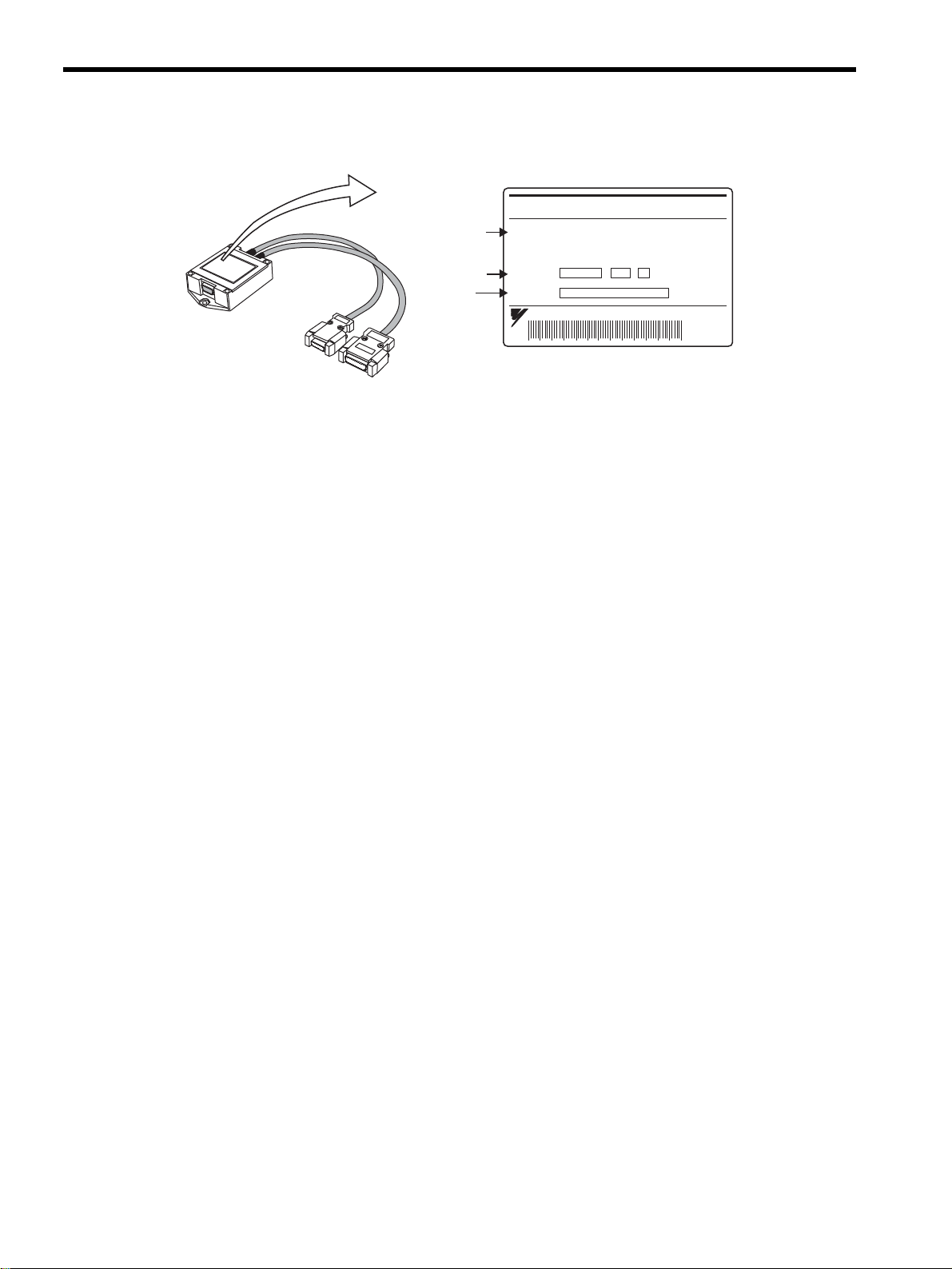
1.1.3 SERVOPACKs
Coilassembly
Servomotor
model
Ratings
OrderNo.
SerialNo.
Magneticway
Servomotor
model
OrderNo.
SerialNo.
Nameplate
LinearSERVOMOTOR
TYPE
SGLFW-35A120A
200 W
1.3 A
80 N
200 V
2.5 m/s
O/N
S/N
YASKAWAELECTRICMADEINJAPAN
DATE
Nameplate
YASKAWA
TYPE:
SGLFM-20756A
O/N
S/N
MADEINJAPAN DATE
ins.B
1
SGDHfor30Wto5.0kW SGDHfor7.5kW
SERVOPACK
SERVOPACK
model
Applicable
powersupply
Serial
number
MODEL
AC-INPUT AC-OUTPUT
VOLTS
Hz
PHASE
AMPS
S/N
YASKAWAELECTRIC
SGDH-30AE
200-230
60/60
3
18.6
VOLTS
PHASE
AMPS
KU(MP)
412808-15-1
MADEINJAPAN
0-230
3
24.8
3.0(4.0)
Applicable
motor
capacity
1-3
Page 19
1 Outline
1.1.4 Serial Converter Units
1.1.4 Serial Converter Units
Nameplate
Serial
converter
model
OrderNo.
SerialNo.
SERIALCONVERTER
MODELJZDP-A006-156
For:-
O/N
S/N
YASKAWAELECTRICCORPORATION
--
JAPAN
1-4
Page 20

1.2 Product Part Names
1.2.1 Linear Servomotors
Coreless SGLGW and SGLGM
(1)
Magneticway
Hallsensorcable
Maincircuitcableforlinearservomotor
1.2 Product Part Names
1
Coilassembly
Hallsensorunit
(2) SGLFW and SGLFM With F-type Iron Core
Coilassembly
Hallsensorcable
Hallsensor
unit
Maincircuitcablefor
linearservomotor
SGLTW and SGLTM With T-type Iron Core
(3)
Coilassembly
Hallsensorcable
Magneticway
Spacerfor
installation
Hallsensorunit
Maincircuitcablefor
linearservomotor
Magneticway
1-5
Page 21
1 Outline
1.2.2 SERVOPACKs
1.2.2 SERVOPACKs
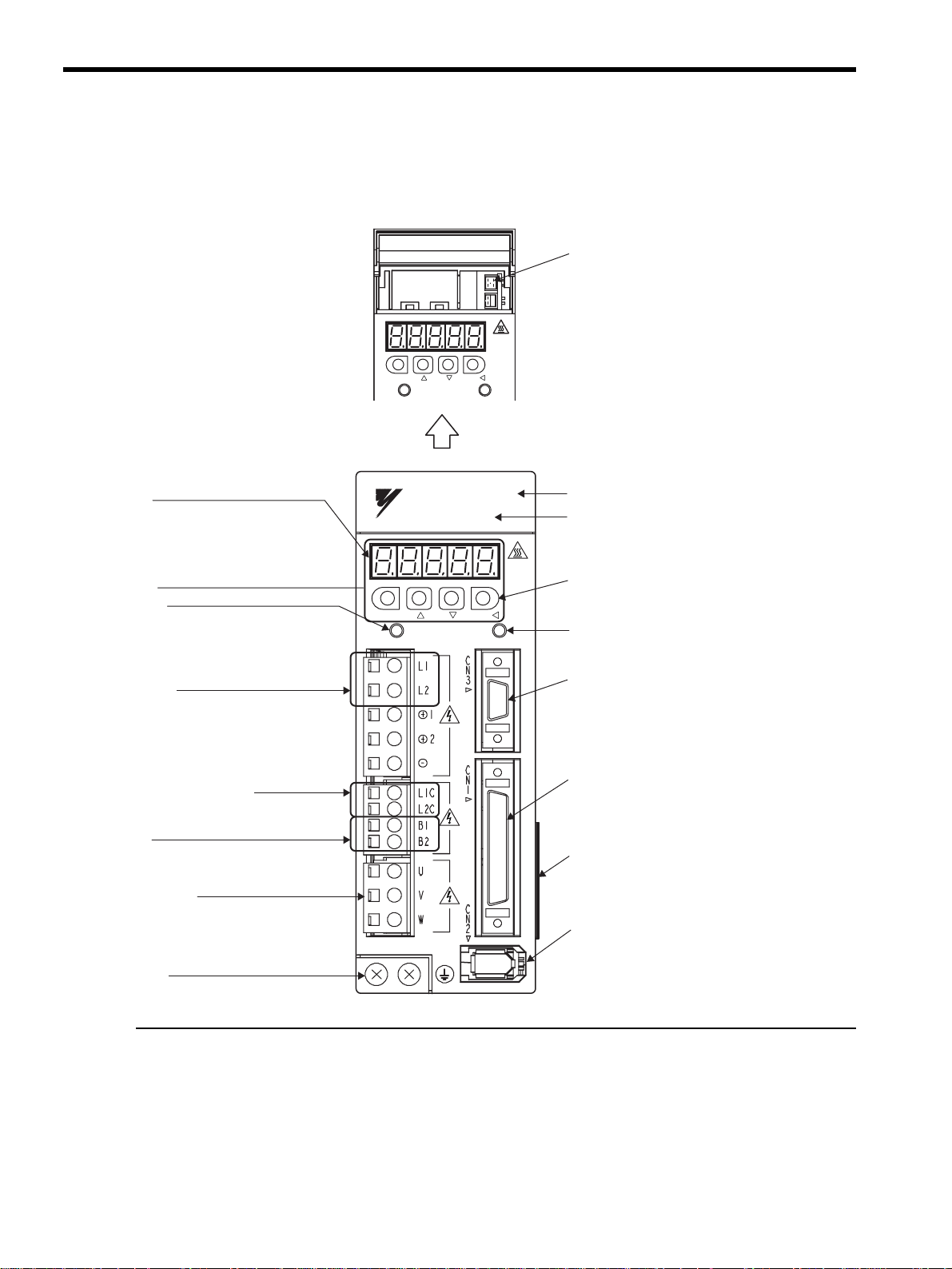
(1) SGDH for 50 W to 5.0 kW
Withthefrontcoveropen
MODE/SET DATA/
CHARGE POWER
CN5Analogmonitorconnector
Usedtomonitormotorspeed,force
reference,andothervaluesthrough
aspecialcable.
Referto5.5 Analog Monitor
Paneldisplay
5-digit,7-segmentLEDusedtodisplay
SERVOPACKstatus,alarmstatus,andother
valueswhenparametersareinput.
Referto3.1.2KeyNamesandFunctions.
Paneloperator
Chargeindicator
Lightswhenthemaincircuitpowersupplyis
ONandstayslitaslongasthemaincircuitpower
supplycapacitorremainscharged.Therefore,
donottouchtheSERVOPACKevenafterthepower
supplyisturnedOFFiftheindicatorislit.
Maincircuitpower
supplyterminals
Usedformaincircuitpowersupplyinput.
Controlpowersupplyterminals
Usedforcontrolpowersupplyinput.
Regenerative
resistorconnectingterminals
Usedtoconnectexternalregenerativeresistors.
Servomotorterminals
Connectstotheservomotorpowerline.
YASKAWA
MODE/SET
YASKAWA
SERVOPACK
SGDH-
CHARGE POWER
DATA/
Frontcover
SERVOPACKmodel
Referto2.3SERVOPACKModel
Designations.
Panelkeys
Usedtosetparameters.
PowerONindicator
LightswhenthecontrolpowersupplyisON.
CN3Connectorforpersonalcomputermonitoring
anddigitaloperator
Usedtocommunicatewithapersonalcomputer
ortoconnectadigitaloperator.
CN1I/Osignalconnector
Usedforreferenceinputsignalsand
sequenceI/Osignals.
Nameplate(sideview)
IndicatestheSERVOPACKmodelandratings.
Referto1.1.3SERVOPACKs.
CN2Encoderconnector
Connectstotheencoderintheservomotor.
Groundterminal
Besuretoconnecttoprotectagainstelectricalshock.
1-6
Page 22
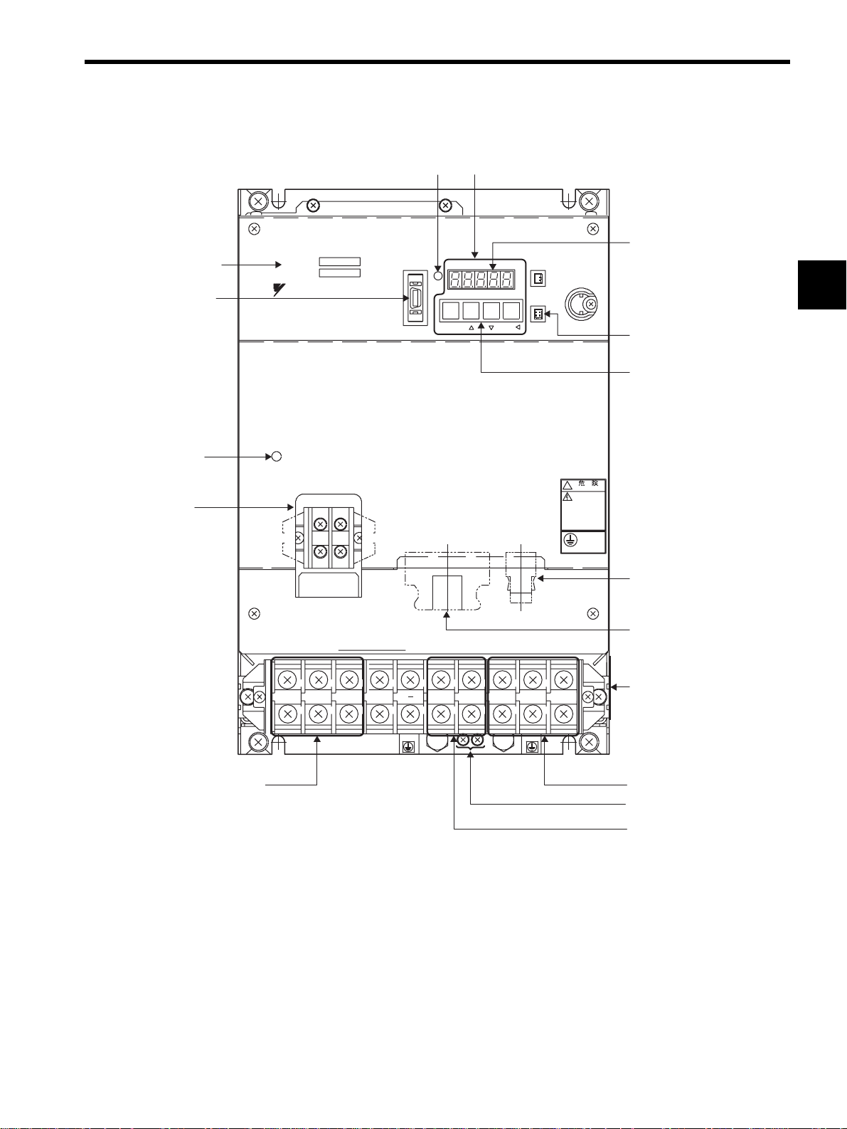
(2) SGDH for 7.5 kW
1.2 Product Part Names
SERVOPACKmodel
CN3Connectorfor
personalcomputer
monitoringand
digitaloperator
Chargeindicator
Controlcircuit
∗
terminal
SERVOPACK 200V
SGDH-
Ve r.
YASKAWA
CHARGE
L1C
L2C
Powerindicator
POWER
MODE/SET
CN3
CN1 CN2
Paneloperator
DATA/
CN8
CN5
BATTERY
!
WARNING
Paneldisplay
1
CN5Analog
monitorconnector
Panelswitch
CN2Encoderconnector
CN1I/Osignalconnector
Nameplate(sideview)
Servomotorterminals:U,V,W
Groundterminal
Maincircuitpowersupply
terminals:L1,L2,L3
L1 L2 L3
+
B2B1
U
VW
Regenerativeresistor
connectingterminals:B1,B2
* Control circuit terminal and regenerative resistor connecting terminals differ the position of the termi-
nal block by the SERVOPACK model.
∗
1-7
Page 23

1 Outline
1.3.1 Single-phase, 200 V Main Circuit
1.3 Examples of Servo System Configurations
This section describes examples of basic servo system configuration.
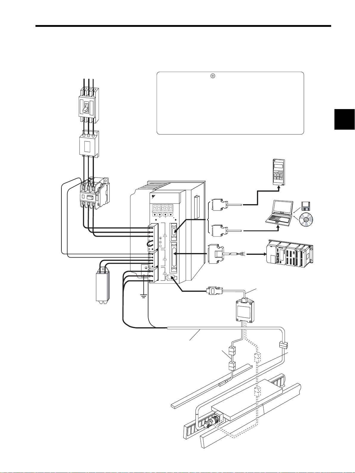
1.3.1 Single-phase, 200 V Main Circuit
Powersupply
Single-phase200VAC
Molded-case
circuitbreaker
(MCCB)
Protectsthepowersupply
linebyshuttingthecircuit
OFFwhenanovercurrent
isdetected.
(Referto2.7.2)
Noisefilter
Eliminatesexternal
noisefromthepower
line.
(Referto2.7.3)
RT
Magnetic
contactor
TurnstheservoON
andOFF.
Installasurge
suppressor.
Referto
2.7.3)
SGDH-AE
SERVOPACK
YASKAWA
SERVOPACK
SGDH-
200V
Digital
operator
(Referto2.7.)
Regenerative
resistor
Connectanexternal
regenerativeresistor
toterminalsB1andB2
iftheregenerative
capacityisinsufficient.
(Referto2.7.4.)
MODE/SET
CHARGE POWER
L1
L2
+1
+2
-
L1C
L2C
B1
B2
U
V
W
Maincircuitcablefor
linearservomotor
(Referto2.6.)
DATA/
C
N
3
C
N
1
C
N
Encoder
cable
(Referto2.6.)
Connectioncable
fordigitaloperator
Connectioncable
forpersonalcomputer
I/Osignalcable
(Referto2.7.1.)
(Referto2.7.1.)
Connectioncable
forserialconverterunit
(Referto2.6.)
Serialconverterunit
(Referto2.5.)
Personalcomputer
Hostcontroller
Connectioncable
forhallsensor
(Referto2.6.)
1-8
Linearscale
(Tobeprovidedby
users.)
(Referto2.7.5.)
Hallsensorunit
CorelessLinearServomotor
Page 24
1.3.2 Three-phase, 200 V Main Circuit
Power supply
Three-phase 200 VAC
Molded-case
circuit breaker
(MCCB)
Protects the power
supply line by shutting
the circuit OFF when
an overcurrent is
detected.
(Refer to 2.7.2.)
Noise filter
Eliminates external noise
from the power line.
(Refer to 2.7.3.)
R S T
*1: The positive terminal for the main circuit is only available for use
in the three-phase (200 VAC, 7.5 kW or more) SERVOPACKs.
Do not use the positive terminals 1 or 2.
*2: Before connecting an external regenerative resistor to
the SERVOPACK, be sure to disconnect the lead between terminals
B2 and B3.
1.3 Examples of Servo System Configurations
1
Regenerative
resistor
Connect an external
regenerative resistor
to terminals B1 and B2
if the regenerative
capacity is insufficient.
(Refer to 2.7.4.)
Magnetic
contactor
Turns the servo
ON and OFF.
Install a surge
suppressor.
(Refer to
2.7.3.)
*2
*1
SGDH-AE
SERVOPACK
YASKAWA
200V
SERVOPACK
SGD
H-
MODE/SET
DATA/
CHARGE POWER
L1
C
N
L2
3
L3
1
2
C
N
1
L1C
L2C
B1
B2
B3
C
U
N
2
V
W
Connection cable for
digital operator
Connection cable for
personal computer
(Refer to 2.7.1.)
I/O signal cable
(Refer to 2.7.1.)
Digital
operator
(Refer to 2.7.1.)
Personal computer
Host controller
Connection cable for
serial converter unit
(Refer to 2.6.)
Serial converter unit
(Refer to 2.5.)
Main circuit cable for
linear servomotor
(Refer to 2.6.)
Linear scale
(To be provided by
users)
(Refer to 2.7.5.)
Encoder
cable
(Refer to 2.6.)
Connection cable
for hall sensor
(Refer to 2.6.)
Linear servomotor with core
1-9
Page 25

1 Outline
1.3.3 Three-phase, 400 V Main Circuit
1.3.3 Three-phase, 400 V Main Circuit
Power supply
Three-phase 400 VAC
R S T
Molded-case
circuit breaker
(MCCB)
Protects the power
supply line by shutting
the circuit OFF when
an overcurrent is
detected.
(Refer to 2.7.2.)
Noise filter
Eliminates external
noise from the power
line.
(Refer to2.7.3.)
Magnetic
contactor
Turns the servo
ON and OFF.
Install a surge
suppressor.
Refer to
2.7.3.)
*1: Use a 24 VDC power supply (To be provided by users).
*2: Before connecting an external regenerative resistor to
the SERVOPACK, be sure to disconnect the lead between terminals
B2 and B3.
Digital
SGDH-DE
operator
(Refer to 2.7.1.)
SERVOPACK
Connection cable
YASKAWA
SERVOPACK
SGD
H-
200V
for digital operator
Personal computer
*1
+
DC power
supply
(24 VDC)
−
Regenerative
resistor
Connect an external
regenerative resistor
to terminals B1 and B2
if the rgenerative capacity
is insufficient.
(Refer to 2.7.4.)
*2
MODE/SET
DATA/
CHARGE POWER
L1
C
N
L2
3
L3
1
2
C
N
1
24V
0V
B1
B2
B3
C
U
N
2
V
W
Connection cable
for personal computer
(Refer to 2.7.1.)
I/O signal cable
(Refer to 2.7.1.)
Host controller
Connection cable for
serial convertr unit
(Refer to 2.6.)
Serial convertr unit
(Refer to 2.5.)
Main circuit cable for
linear servomotor
(Refer to 2.6.)
Encoder
cable
(Refer to 2.6.)
Connection cable
for hall sensor
(Refer to 2.6.)
Linear scale
(To be provided by
users.)
(Refer to 2.7.5.)
1-10
Linear servomotor
wirh core
Page 26

1.4 Applicable Standards
Σ-II Series servodrives conform to the following overseas standards.
1.4.1 North American Safety Standards (UL, CSA)
1.4 Applicable Standards
1.4.2
Model
SERVOPACK • SGDH
* 1. Underwriters Laboratories Inc.
* 2. Canadian Standards Association.
CE Marking
Model
SERVOPACK • SGDH
* TÜV Product Services GmbH
U
R
C
L
US
C
LISTED
∗1
UL
Standards (UL File No.) CSA∗2 Standards
UL508C(E147823)
Low Voltage
Directive
EN50178
EMI EMS
EN55011
class A group 1
CSA C22.2
No.14
EMC Directive
R
US
EN50082-2
or
EN61000-6-2
Certifications
UL
Certifications
TÜV PS
∗
1
Because SERVOPACKs and linear servomotors are built-in type, reconfirmation is
required after being installed in the final product.
1-11
Page 27

2
Selections
2.1 Linear Servomotor Model Designation - - - - - - - - - - - - - - - - - - - - - - - - - - 2-2
2.1.1 Coil Assembly - - - - - - - - - - - - - - - - - - - - - - - - - - - - - - - - - - - - - - - - - - - - - - - - - - - - 2-2
2.1.2 Magnetic Way - - - - - - - - - - - - - - - - - - - - - - - - - - - - - - - - - - - - - - - - - - - - - - - - - - - - 2-2
2.2 SERVOPACK Model Designation - - - - - - - - - - - - - - - - - - - - - - - - - - - - - - 2-3
2.3 Σ-II Series SERVOPACKs and Applicable Linear Servomotors - - - - - - - - - 2-4
2.4 Serial Converter Units Models - - - - - - - - - - - - - - - - - - - - - - - - - - - - - - - - 2-6
2.5 Selecting Cables - - - - - - - - - - - - - - - - - - - - - - - - - - - - - - - - - - - - - - - - - 2-7
2.6 Selecting Peripheral Devices - - - - - - - - - - - - - - - - - - - - - - - - - - - - - - - - - 2-9
2.6.1 Special Options - - - - - - - - - - - - - - - - - - - - - - - - - - - - - - - - - - - - - - - - - - - - - - - - - - - 2-9
2.6.2 Molded-case Circuit Breaker and Fuse Capacity - - - - - - - - - - - - - - - - - - - - - - - - - - 2-11
2.6.3 Noise Filters, Magnetic Contactors, Surge Suppressors and DC Reactors - - - - - - - - 2-12
2.6.4 Regenerative Resistors - - - - - - - - - - - - - - - - - - - - - - - - - - - - - - - - - - - - - - - - - - - - 2-13
2.6.5 Linear Scales - - - - - - - - - - - - - - - - - - - - - - - - - - - - - - - - - - - - - - - - - - - - - - - - - - - 2-14
2
2-1
Page 28
2 Selections
2.1.1 Coil Assembly
2.1 Linear Servomotor Model Designation
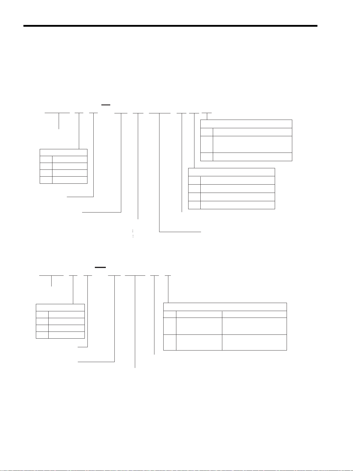
This section describes how to check the model and ratings of the linear servomotor. The alphanumeric codes
after SGL- indicate the specifications.
2.1.1 Coil Assembly
40 A 140 A P
Voltage
200VAC
A
400VAC
D
LinearΣSeries
Linearservomotor
ServomotorModel
Code
Specifications
G
Coreless
F-typeironcore
F
T-typeironcore
T
W:Coilassembly
Magnetheight
WGSGL
2.1.2 Magnetic Way
SGL 40 225 A C
GM
D
CableConnectorforMainCircuitCable
Code
MSconnectororconnectormade
−
byTycoElectronicsAMPK.K.
ConnectormadebyInterconnectron
D
Code
P
C
Withhallsensorandforcedcooling
H
Designrevisionorder
A,B,C
Lengthofcoilassembly
Specifications
Options
Specifications
Withhallsensor
Forcedcooling
LinearΣSeries
Linearservomotor
Model
Code
Specifications
G
Coreless
F
F-typeironcore
T
T-typeironcore
M:Magneticway
Magnetwidth
2-2
Designrevisionorder
A,B,C
Lengthofmagneticway
Code
C
Withmagnetcover
-M
Highthrustforce
Options
Specifications Remarks
Onlyforlinearservomotors
withanironcore
Onlyforcorelesstypes
Page 29
2.2 SERVOPACK Model Designation
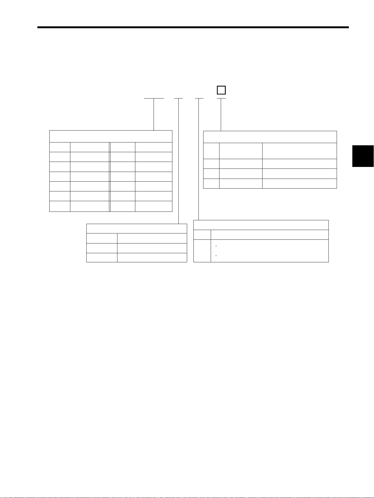
Select the SERVOPACK according to the applied linear servomotor.
10SGDH-AE
2.2 SERVOPACK Model Designation
RatedOutputofApplicableServomotor(kW)
Code
A5
01
02
04
05
08
RatedOutput
0.05
0.10
0.20
0.40
0.45
0.75
Code
Code
10
15
20
30
50
75
PowerSupplyVoltage
A
D
Single/Three-phase,200V
RatedOutput
Voltage
Three-phase,400V
1.0
1.5
2.0
3.0
5.0
7.5
Code Specifications
-
Base-mounted
-P
Duct-ventilated
-R
Rack-mounted
Code
Forforce,speed,andpositioncontrol
E
Applicableforvariousapplicationmodules
MountingMethod
RatedOutputof
ApplicableServomotor(kW)
0.05to7.5
7.5
0.05to5.0
Model(Fixed)
Remarks
2
2-3
Page 30
2 Selections
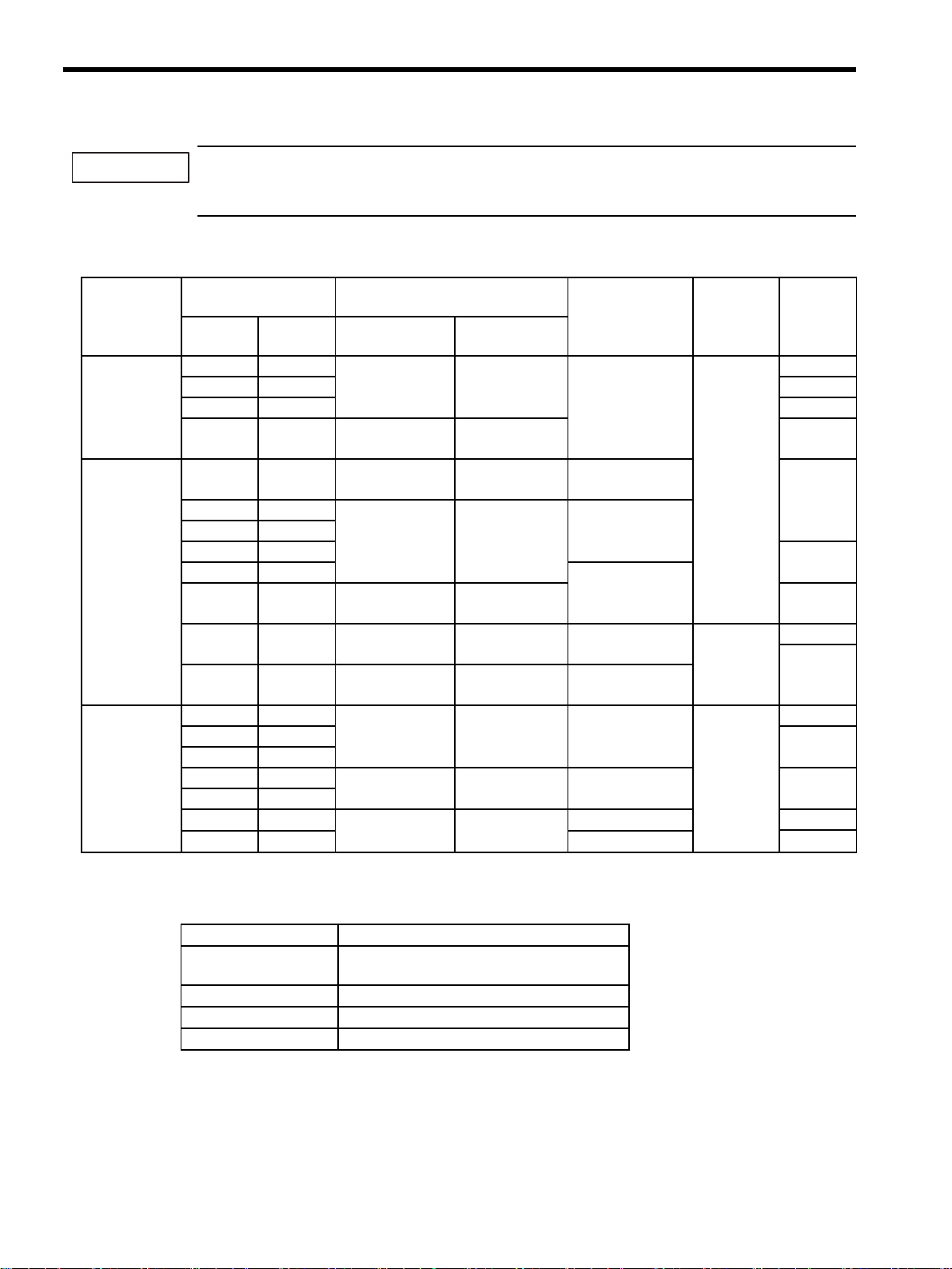
2.3
Σ-II Series SERVOPACKs and Applicable Linear Servomotors
Linear Σ Series Linear Servomotor
SGLGW
(Coreless)
17 models
SGLFW
(With F-type iron core)
12 models
When a
Standardforce
Magnetic
Way is used.
When a
High-force
Magnetic
Way is used.
30A050B
30A080B
40A140B
40A253B
40A365B
60A140B
60A253B
60A365B
90A200A
90A370A
90A535A
40A140B
40A253B
40A365B
60A140B
60A253B
60A365B
20A090A
20A120A
35A120A
35A230A
50A200B
50A380B
1ZA200B
1ZA380B
35D120A
35D230A
50D200B
50D380B
1ZD200B
1ZD380B
Σ-II Series SGDH SERVOPACK
Single-phase
200 VAC
A5AE −−
01AE −−
01AE −−
02AE −−
04AE −−
02AE −−
04AE −−
− 08AE −
− 15AE −
− 20AE −
− 30AE −
02AE −−
04AE −−
− 05AE −
02AE −−
− 05AE −
− 10AE −
02AE −−
02AE −−
02AE −−
− 05AE −
− 08AE −
− 15AE −
− 15AE −
− 20AE −
−−05DE
−−05DE
−−10DE
−−15DE
−−15DE
−−20DE
Three-phase
200 VAC
Three-phase
400 VAC
2-4
Page 31

Linear Σ Series Linear Servomotor
SGLTW
(With T-type iron core)
22 models
Note: The model combinations shown in this table are used when the maximum rated force of the appli-
cable linear servomoter is required. To suppress rises in temperature, larger linear servomotors are
used in some cases. If so, the SERVOPACK capacity can be lowered if using a motor at a lower
force than the rated force. Calculate the required current and select a model with a margin of
approximately 20%. An allowance can be made for up to 1/3 of the combined capacity of the linear
servomotor and SERVOPACK in the table.
20A170A
20A320A
20A460A
35A170A
35A320A
35A460A
35A170H
35A320H
50A170H
50A320H
40A400B
40A600B
80A400B
80A600B
35D170H
35D320H
50D170H
50D320H
40D400B
40D600B
80D400B
80D600B
2.3 Σ-II Series SERVOPACKs and Applicable Linear Servomotors
Σ-II Series SGDH SERVOPACK
Single-phase
200 VAC
− 05AE −
− 10AE −
− 15AE −
− 08AE −
− 15AE −
− 20AE −
− 08AE −
− 15AE −
− 08AE −
− 15AE −
− 20AE −
− 30AE −
− 50AE −
− 75AE −
−−15DE
−−30DE
−−15DE
−−20DE
−−30DE
−−50DE
−−75DE
−−75DE
Three-phase
200 VAC
Three-phase
400 VAC
2
2-5
Page 32

2 Selections
2.4 Serial Converter Units Models
A003JZDP 001
Symbol
A003
A005
A006
A008
SerialConverterUnitModel
Appearance
Applicable
LinearScale
Madeby
Heidenhain
Madeby
Renishaw
Madeby
Heidenhain
Madeby
Renishaw
HallSensor
None
None
Yes
Yes
ServomotorModel
SGLGW-
(Coreless)
Whena
standardforce
magnetic
wayisused.
SGLGW+
SGLGM-M
(Coreless)
Whena
high-force
magnetic
wayisused.
SGLFW-
(Ironcore,
F-type)
ApplicableLinearServomotor
Symbol
30A050B
30A080B
40A140B
40A253B
40A365B
60A140B
60A253B
60A365B
90A200A
90A370A
90A535A
40A140B
40A253B
40A365B
60A140B
60A253B
60A365B
20A090A
20A120A
35A120A
35A230A
50A200B
50A380B
1ZA200B
1ZA380B
50D200B
50D380B
1ZD200B
1ZD380B
158
156
001
002
003
004
005
006
101
102
103
063
059
060
061
062
047
017
018
019
020
181
182
183
184
189
190
191
192
ServomotorModel
SGLTW-
(Ironcore,
T-type)
20A170A
20A320A
20A460A
35A170A
35A320A
35A460A
35A170H
35A320H
50A170H
50A320H
40A400B
40A600B
80A400B
80A600B
35D170H
35D320H
50D170H
50D320H
40D400B
40D600B
80D400B
80D600B
Symbol
011
012
013
014
015
016
105
106
108
109
185
186
187
188
193
194
195
196
197
198
199
200
2-6
Note: When using a 400-V winding linear servomotor with a 200-V SERVOPACK, the parameters in the
serial converter should be changed. Contact your Yaskawa representatives.
Page 33

2.5 Selecting Cables
L1
L2
L3
U
V
W
L1C
L2
B1
B2
B3
1
2
C
N
3
C
N
1
C
N
2
r
YASKAWA
200V
SERVOPACK
SGDH-
MODE/SET DATA/
POWER
CHARGE
CN2
Serialconverter
unit
SERVOPACK
Note:Thefollowingtwomaincircuitcables
areavailableforthelinearservomotor.
MSconnectororconnectormadeby
TycoElectronicsAMPK.K.
ConnectormadebyInterconnectron
2.5 Selecting Cables
2
Linearscale
(Tobeprovided
byusers.)
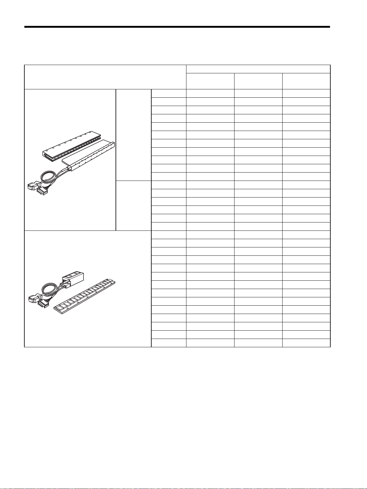
Name Connection
c
Linear Servomotor Main
Circuit Cables
Between SERVOPACK
and linear
servomotor
Linearservomotor
Applicable
Linear Servo-
motor Model
SGLGW-30,-40
and -60
SGLFW-20
SGLFW-35
SGLGW-90
SGLFW-50,-1Z
SGLTW-20,-35
SGLTW-40,-80
Hallsensor
unit
Cable
Length
1 m
3 m
5 m
10 m
15 m
20 m
1 m
3 m
5 m
10 m
15 m
20 m
1 m
3 m
5 m
10 m
15 m
20 m
Cable Type Specifications
JZSP-CLN11-01
JZSP-CLN11-03
JZSP-CLN11-05
JZSP-CLN11-10
JZSP-CLN11-15
JZSP-CLN11-20
JZSP-CLN21-01
JZSP-CLN21-03
JZSP-CLN21-05
JZSP-CLN21-10
JZSP-CLN21-15
JZSP-CLN21-20
JZSP-CLN39-01
JZSP-CLN39-03
JZSP-CLN39-05
JZSP-CLN39-10
JZSP-CLN39-15
JZSP-CLN39-20
SERVOPACK
end
SERVOPACK
end
SERVOPACK
end
Linearservomotor
end
Linearservomoto
end
Linearservomotor
end
2-7
Page 34

2 Selections
Name Connection
c
Linear Servomotor Main
Circuit Cables
d
Encoder
Cables
Between SERVOPACK
and linear
servomotor
Between serial converter unit and linear scale
e
Connection
cables for serial converter
unit
f
Connection
cables for hall
sensor
Between SERVOPACK
connector CN2 and
serial converter unit
Between serial converter unit and hall sensor
unit
* The main circuit’s cable connector is made by Interconnectron.
A connector is not provided on the linear servomotor end of the main circuit cable, type JZSP-
Note:
CLN39-. The user must provide the connector on the linear servomotor end.
Applicable
Linear Servo-
motor Model
SGLW-
D
For 200 VAC *
SGLW-
D
For 400 VAC *
All models
All models
All models
Cable
Length
1 m
3 m
5 m
10 m
15 m
20 m
1 m
3 m
5 m
10 m
15 m
20 m
1 m
3 m
5 m
10 m
15 m
1 m
3 m
5 m
10 m
15 m
20 m
1 m
3 m
5 m
10 m
15 m
Cable Type Specifications
JZSP-CLN14-01
JZSP-CLN14-03
JZSP-CLN14-05
JZSP-CLN14-10
JZSP-CLN14-15
JZSP-CLN14-20
JZSP-CLN15-01
JZSP-CLN15-03
JZSP-CLN15-05
JZSP-CLN15-10
JZSP-CLN15-15
JZSP-CLN15-20
JZSP-CLL00-01
JZSP-CLL00-03
JZSP-CLL00-05
JZSP-CLL00-10
JZSP-CLL00-15
JZSP-CLP70-01
JZSP-CLP70-03
JZSP-CLP70-05
JZSP-CLP70-10
JZSP-CLP70-15
JZSP-CLP70-20
JZSP-CLL10-01
JZSP-CLL10-03
JZSP-CLL10-05
JZSP-CLL10-10
JZSP-CLL10-15
SERVOPACK
end
SERVOPACK
end
Serialconverterunit
end
SERVOPACK
end
Serialconverterunit
end
Linearservomotor
end
Linearservomotor
end
Linearscale
end
Serialconverterunit
end
Hallsensorunit
end
2-8
Page 35

2.6 Selecting Peripheral Devices
L1
L2
L3
U
V
W
L1C
L2
B1
B2
B3
1
2
C
N
3
C
N
1
C
N
2
L1
L2
L3
U
V
W
L1C
L2
B1
B2
B3
1
2
C
N
3
C
N
1
C
N
2
2.6.1 Special Options
Connectioncable
fordigitaloperator
YASKAWA
200V
SERVOPACK
SGDH-
MODE/SET DATA/
CHARGE
POWER
CN3
Connectioncable
forpersonalcomputer
Digitaloperator
2.6 Selecting Peripheral Devices
Personal
computer
2
YASKAWA
SERVOPACK
SGDH-
MODE/SET DATA/
CHARGE
I/Osignalcable
Hostcontroller
CN1
Analogmonitorcable
CN5
CN8
NS300
CN11
CN6
CN4
NS600
CN7
CN4
CN6
7
8
6
9
0
X
5
4
10
1
3
2
7
8
6
9
X
0
5
4
1
1
3
2
CN11
7
8
6
9
D
0
5
R
4
1
3
2
C
N
11
M
S
N
S
CN6
NS500
6
CN4
CN10
NS100
S
W
200V
Connector
POWER
1
A
R
S
W
2
C
N
6
A
C
N
6
B
C
N
4
CN6A
CN6B
CN4
MECHATROLINK-I
I/FUnit
(NS100)
DeviceNet
I/FUnit
(NS300)
PROFIBUS-DP
I/FUnit
(NS500)
INDEXER
Module
(NS600)
2-9
Page 36

2 Selections
2.6.1 Special Options
c
CN1
I/O Signal
Cables
Name Length Type Specifications
Terminal block and 0.5 m connection
Connector terminal block
converter unit
Cable with
loose wires at
one end
1 m JZSP-CKI01-1 Loose wires at host controller end
2 m JZSP-CKI01-2
3 m JZSP-CKI01-3
JUSP-TA50P
cable
With connection cable (1 m)
d Digital Operator
JUSP-OP02A-2
1 m JZSP-CMS00-1
CN3
e
Connection Cable
1.5 m JZSP-CMS00-2
for Digital Operator
2 m JZSP-CMS00-3
CN3
f
Connection Cable for Personal
2 m JZSP-CMS02
Computer
CN5
g
Analog Monitor Cable
1 m
JZSP-CA01 or
DE9404559
Name Type
MECHATROLINK-I I/F Unit (NS100) JUSP-NS100
Application Module
h
∗
DeviceNet I/F Unit (NS300) JUSP-NS300
PROFIBUS-DP I/F Unit (NS500) JUSP-NS500
INDEXER Module (NS600) JUSP-NS600
* For details, refer to the manuals of each application module.
Only required when using Σ series
Digital Operator JUSP-OP02A-1.
SERVOPACK
end
Operator
end
D-Sub 9-pin (For DOS/V)
SERVOPACK
end
SERVOPACKend
Personal
computerend
Monitorend
2-10
Page 37

2.6.2 Molded-case Circuit Breaker and Fuse Capacity
Current Capacity of the
Main
Circuit
Power
Supply
Singlephase
200 V
Threephase
200 V
Threephase
400 V
SERVOPACK
Model
Power Supply
Capacity per
SERVOPACK
Capacity
(kW)
SGDH-
(kVA)
0.05 A5AE 0.25
0.10 01AE 0.40
0.20 02AE 0.75
0.40 04AE 1.2 8
0.45 05AE 1.4 4
0.75 08AE 1.9
1.0 10AE 2.3
1.5 15AE 3.2 10
2.0 20AE 4.3 13
3.0 30AE 5.9 17
5.0 50AE 7.5 28 67A
7.5 75AE 15.5 41
0.45 05DE 1.1 1.6
1.0 10DE 2.3 3.4
1.5 15DE 3.2 4.6
2.0 20DE 4.9 7.1
3.0 30DE 6.7 9.7
5.0 50DE 10.3 14.9 78A
7.5 75DE 15.4 22.3
* 1. Nominal value at the rated load. The specified derating is required to select an appropriate
fuse capacity.
* 2. Cutoff characteristics (25
°C): 300% five seconds min. and inrush current of 20ms.
* 3. A preventive circuit for inrush current is not built in the 24 VDC control power supply. The
protective circuit must be designed by the customer.
* 4. Make sure the current capacity is accurate. For the SERVOPACK with the cooling fan built-
in, an inrush current flows; 200 % of the current capacity in the table above for two seconds,
when turning ON the control circuit power supply to start the fan working.
Note: Do not use a fast-acting fuse. Because the SERVOPACK’s power supply is a capacitor
input type, a fast-acting fuse may blow when the power is turned ON.
Molded-case Circuit Breaker
and the Fuse (A
Main Circuit
Power Supply
4
7
2.6 Selecting Peripheral Devices
∗1,∗2
)
rms
Control Cir-
cuit Power
Supply
Power Supply
Inrush Current
Main Circuit
0.13 63A 60A
118A
4
∗
0.15
63A
4
0.27
∗
40A
10A
4
∗
0.7
20A
4
1.2
∗
20A
Control Cir-
cuit Power
Supply
60A
24 VDC
(
)
2
3
∗
2-11
Page 38
2 Selections
2.6.3 Noise Filters, Magnetic Contactors, Surge Suppressors and DC Reactors
IMPORTANT
The SGDH SERVOPACK does not include a protective grounding circuit. Install a ground-fault protector
to protect the system against overload and short-circuit or protective grounding combined with the moldedcase circuit breaker.
2.6.3 Noise Filters, Magnetic Contactors, Surge Suppressors and DC Reactors
Main Circuit
Power
Supply
Single-phase
200 V
Three-phase
200 V
Three-phase
400 V
Note: 1. If some SERVOPACKs are wired at the same time, select the proper magnetic contactors accord-
SERVOPACK Model
Capacity
(kW)
0.05 A5AE
0.10 01AE X5071
0.20 02AE X5070
0.40 04AE FN2070-10/07
0.45 05AE FN258L-7/07
0.75 08AE
1.0 10AE
1.5 15AE
2.0 20AE
3.0 30AE FN258L-30/07
5.0 50AE FMAC-0934-5010
7.5 75AE FMAC-0953-6410
0.45 05DE
1.0 10DE
1.5 15DE
2.0 20DE
3.0 30DE
5.0 50DE
7.5 75DE
ing to the total capacity.
2. The following table shows the manufacturers of each device.
SGDH
Recommended Noise Filter
-
Type Specifications
FN2070-6/07
FN258L-16/07
FN258L-7/07
FN258L-16/07
FS5559-35-33
Single-phase
250 VAC, 6 A
Single-phase
250 VAC, 10 A
Three-phase
480 VAC, 7 A
Three-phase
480 VAC, 16 A
Three-phase
480 VAC, 30 A
Three-phase
440 VAC, 50 A
Three-phase
440 VAC, 64 A
Three-phase
480 VAC, 7 A
Three-phase
480 VAC, 16 A
Three-phase
480 VAC, 35 A
Magnetic
Contactor
HI-11J (20 A)
HI-11J (20 A)
HI-15J (35 A)
HI-20J (35 A)
HI-25J (50 A)
HI-35J (65 A)
HI-15JCU (35 A)
HI-20JCU (35 A)
HI-25JCU (50 A)
HI-35JCU (65 A)
Surge
Suppressor
TU-25C240
TU-65C240
Built-in
DC
Reactor
−
X5069
X5061
X5060
X5059
X5068
−
X5074
X5075
X5076
X5077
−
2-12
Peripheral Device Manufacturer
Noise Filter
Magnetic Contactor Yaskawa Controls Co., Ltd.
Surge Suppressor Yaskawa Controls Co., Ltd.
DC Reactor Yaskawa Controls Co., Ltd.
FN, FS type: Schaffner Electronic
FMAC type: Timonta AG
Page 39

2.6.4 Regenerative Resistors
2.6 Selecting Peripheral Devices
SERVOPACK Model
Main Circuit
Power Supply
Single-phase
200 V
Three-phase
200 V
Three-phase
400 V
* 1. For the optional JUSP-RA05 Regenerative Resistor Unit.
* 2. For the optional JUSP-RA18 Regenerative Resistor Unit.
Capacity
(kW)
0.05 A5AE
0.10 01AE
0.20 02AE
0.40 04AE
0.45 05AE
0.75 08AE
1.0 10AE
1.5 15AE 30 70
2.0 20AE 25 140
3.0 30AE 12.5 140
5.0 50AE 8 280
7.5 75AE
0.45 05DE
1.0 10DE
1.5 15DE
2.0 20DE
3.0 30DE
5.0 50DE 32 180
SGDH-
Resistance
Regenerative Resistor
Built-in
(Ω)
−−−
50 60
1
∗
(3.13)
108 70
45 140
2
∗
(18)
Capacity
(W)
1
∗
(1760)
2
∗
(880)
Externally
connected
2
−
JUSP-RA05
−
JUSP-RA187.5 75DE
Note: 1. If the SERVOPACK cannot process the regenerative power, an external regenerative resistor is
required.
2. The following table shows the manufacturers of each device.
Peripheral Device Manufacturer
External Regenerative Resistor Iwaki Wireless Research Institute
External Regenerative Unit Yaskawa Electric Corporation
2-13
Page 40

2 Selections
2.6.5 Linear Scales
2.6.5 Linear Scales
Encoder
Manufacturer Type Output Signal
Resolution
m/pulse
(µ
)
Scale Pitch
(µm)
Output
Resolution
Pn281
(
)
1 to 31 5
Renishaw Inc. RGH22B
0.078 20
32 to 63 4
64 to 127 2
128 to 255 1
1 to 63 5
LIDA187
0.156 40
64 to 127 4
128 to 255 2
Heidenhain
Corp.
LIDA487
LIDA489
1Vpp
Analog voltage
0.078 20
1 to 31 5
32 to 63 4
64 to 127 2
128 to 255 1
1 to 31 1.0
LIF181
0.016 4
32 to 63 0.8
64 to 127 0.4
128 to 255 0.2
Note: 1. The linear scale signal is multiplied by eight bits (256 segmentation) inside the serial converter
unit.
2. Using the zero-point signal with a linear scale made by Renishaw Inc. may cause a deviation in
the home position. If so, adjust the setting so that the zero-point is output only in one direction
by using BID/DIR signal.
3. This list does not cover all the applicable types of linear scales. And, the linear scales listed in
the table may not be applicable or available if their specifications have been modified or their
production has been stopped.
Check the most recent catalog of the linear scale manufacturer to select a linear scale that meets
the specifications.
4. Select a linear scale so that the total current consumption of the linear scale, serial converter unit,
and hall sensor is 190 mA max.
5. At parameter (Pn280), set the scale pitch of the linear scale so that it satisfies the following condition. Otherwise, satisfactory control cannot be obtained.
Max. Speed of
Applicable Linear
Servomotor
m/s
(
)
2-14
64000
Pn280(Scale pitch (µm))
Examples
Correct: 1,2,4,8,10,16,20,40
Incorrect: 3,5,12,18
must result in an integer number
Page 41

3
Digital Operator/Panel Operator
3.1 Functions on Digital Operator/Panel Operator - - - - - - - - - - -3-2
3.1.1 Connecting the Digital Operator - - - - - - - - - - - - - - - - - - - - - - - - - - - 3-2
3.1.2 Key Names and Functions - - - - - - - - - - - - - - - - - - - - - - - - - - - - - - - 3-3
3.1.3 Basic Mode Selection and Operation - - - - - - - - - - - - - - - - - - - - - - - - 3-4
3.1.4 Status Display - - - - - - - - - - - - - - - - - - - - - - - - - - - - - - - - - - - - - - - - 3-6
3.2 Operation in Utility Function Mode (Fn) - - - - - - - - - - - -3-8
3.2.1 List of Utility Function Modes - - - - - - - - - - - - - - - - - - - - - - - - - - - - - 3-8
3.2.2 Alarm Traceback Data Display (Fn000) - - - - - - - - - - - - - - - - - - - - - - 3-9
3.2.3 JOG Mode Operation (Fn002) - - - - - - - - - - - - - - - - - - - - - - - - - - - - 3-10
3.2.4 Zero-point Search Mode (Fn003) - - - - - - - - - - - - - - - - - - - - - - - - - 3-11
3.2.5 Parameter Settings Initialization (Fn005) - - - - - - - - - - - - - - - - - - - - 3-12
3.2.6 Alarm Traceback Data Clear (Fn006) - - - - - - - - - - - - - - - - - - - - - - - 3-13
3.2.7 Automatic Offset-adjustment of Motor Current Detection Signal
(Fn00E) - - - - - - - - - - - - - - - - - - - - - - - - - - - - - - - - - - - - - - - - - - - 3-14
3.2.8 Manual Offset-adjustment of Motor Current Detection Signal (Fn00F) 3-15
3.2.9 Password Setting (Protects Parameters from Being Changed)
(Fn010) - - - - - - - - - - - - - - - - - - - - - - - - - - - - - - - - - - - - - - - - - - - 3-16
3.2.10 Motor Models Display (Fn011) - - - - - - - - - - - - - - - - - - - - - - - - - - - 3-17
3.2.11 Software Version Display (Fn012) - - - - - - - - - - - - - - - - - - - - - - - - 3-18
3.2.12 Application Module Detection Results Clear (Fn014) - - - - - - - - - - - 3-19
3
3.3 Operation in Parameter Setting Mode (Pn) - - - - - - - - 3-20
3.3.1 Setting Parameters - - - - - - - - - - - - - - - - - - - - - - - - - - - - - - - - - - - 3-20
3.3.2 Input Circuit Signal Allocation - - - - - - - - - - - - - - - - - - - - - - - - - - - - 3-24
3.3.3 Output Circuit Signal Allocation - - - - - - - - - - - - - - - - - - - - - - - - - - - 3-28
3.4 Operation in Monitor Mode (Un) - - - - - - - - - - - - - - - - 3-30
3.4.1 List of Monitor Modes - - - - - - - - - - - - - - - - - - - - - - - - - - - - - - - - - - 3-30
3.4.2 Sequence I/O Signal Monitor Display - - - - - - - - - - - - - - - - - - - - - - - 3-31
3.4.3 Operation in Monitor Mode - - - - - - - - - - - - - - - - - - - - - - - - - - - - - - 3-32
3.4.4 Monitor Display of Reference Pulse Counter and
Feedback Pulse Counter - - - - - - - - - - - - - - - - - - - - - - - - - - - - - - - 3-33
3.4.5 Allowable Maximum Motor Speed for Dividing Ratio Monitor
(For the software version 32 or later) - - - - - - - - - - - - - - - - - - - - - - - 3-34
3.4.6 Hall Sensor Signal Monitor (For the software version 32 or later) - - - 3-34
8-1
Page 42

3 Digital Operator/Panel Operator
SGDH-
200V
3.1.1 Connecting the Digital Operator
3.1 Functions on Digital Operator/Panel Operator
This section describes the basic operations of the digital operator (hereinafter called the digital operator) and the
panel operator (hereinafter called the panel operator) for setting the operating conditions. Set parameters and
JOG operation, and display status using these operators. For the operation of the digital operator (Model: JUSPOP02A-2), refer to
3.1.1 Connecting the Digital Operator
Two types of digital operators are available. One is a built-in operator that has a panel indicator and switches
located on the front panel of the SERVOPACK. This type of digital operator is also called a panel operator. The
other one is a hand-held operator (JUSP-OP02A-2 digital operator), which can be connected to the SERVOPACK with connector CN3 of the SERVOPACK.
There is no need to turn OFF the SERVOPACK to connect this hand-held operator to the SERVOPACK. Refer to
the following illustrations to connect the digital operator to the SERVOPACK.
Σ
-II Series SGMH/SGDM Digital Operator Operation Manual (TOE-S800-34).
IMPORTANT
Digital Operator
JUSP-OP02A-2
.
.
..
DIGITAL
ALARM
RESET
JOG
SVON
OPERATOR
JUSP-OP02A
DSPL
SET
YASKAWA
SERVOPACK
DATA
ENTER
.
Panel Operator
YASKAWA
SERVOPACK
MODE/SET
DATA/
CN3
A dedicated cable is used to
connect the digital operator
SERVOPACK
to the SERVOPACK.
If the digital operator is connected to the SERVOPACK, the panel operator does not display anything.
3-2
Page 43

3.1.2 Key Names and Functions
Key names and functions for the digital operator and the panel operator are explained below.
Set parameters and JOG operation, and display status using the panel operator.
3.1 Functions on Digital Operator/Panel Operator
Digital Operator
DIGITAL
SERVOPACK
OPERATOR
JUSP-OP02A
ALARM
DSPL
SET
RESET
JOG
DATA
SVON
ENTER
YASKAWA
SERVOPACK
Panel Operator
Key
Digital Operator Panel Operator
ALARM
RESET
(RESET Key)
DSPL
SET
(DSPL/SET Key)
DATA
ENTER
(DATA/ENTER Key)
(UP Key)
(DOWN Key)
Press simultaneously
+
MODE/SET
(MODE/SET Key)
DATA /
(DATA/SHIFT Key)
(UP Key)
(DOWN Key)
−
(RIGHT Key)
(LEFT Key)
JOG
SVON
(SVON Key)
DATA /
(DATA/SHIFT Key)
MODE/SET
(MODE/SET Key)
Function
To reset the servo alarm.
Note 1. The servo alarm can be reset by /ALM-RST (CN1-44)
input signal.
2. The servo alarm need not be reset if the control power
supply is turned OFF.
To select a basic mode, such as the status display mode, utility
function mode, parameter setting mode, or monitor mode.
Can be also used to set the data.
To display parameter setting and set value.
Press the UP Key to increase the set value.
For JOG operation, this key is used as Forward Run Start Key.
Press the DOWN Key to decrease the set value.
For JOG operation, this key is used as Reserve Run Start Key.
Press the RIGHT Key to shift to the next digit on the right.
Press the LEFT or DATA/SHIFT Key to shift to the next digit on
the left.
Press the SVON or MODE/SET Key to perform servo ON/OFF
in the JOG operation with the operator.
IMPORTANT
When an alarm occurs, remove the cause, and then reset the alarm. Refer to 11.1 Troubleshooting.
3
3-3
Page 44

3 Digital Operator/Panel Operator
3.1.3 Basic Mode Selection and Operation
3.1.3 Basic Mode Selection and Operation
The basic modes include: Status display mode, Utility Function Mode, Parameter Setting Mode, and Monitor
Mode.
Select a basic mode to display the operation status, set parameters and operation references.
The basic mode is selected in the following order.
(1) Using the Digital Operator
Turn ON the power
Press DSPL/SET Key.
A basic mode is selected in the following order.
Status Display Mode (Refer to 8.1.4.)
Press .
DSPL
SET
DATA
Press .
ENTER
Fn: Utility Function Mode
(Refer to 8.2)
Repeat
Press .
DSPL
SET
DATA
Press .
ENTER
Pn: Parameter Setting Mode
(Refer to 8.3)
Press .
Press .
DSPL
SET
DSPL
SET
DATA
Press .
ENTER
Pn: Monitor Mode
(Refer to 8.4)
Press DSPL/SET Key and UP or DOWN Key to select the desired parameter number.
Then, press DATA/ENTER Key to display the contents of selected parameter number
in the selected mode. (Refer to each operation instruction described later.)
3-4
Page 45

(2) Using the Panel Operator
3.1 Functions on Digital Operator/Panel Operator
Turn ON the power
Repeat
Press MODE/SET Key and UP or DOWN Key to select the desired parameter number.
Then, press DATA/SHIFT Key for more than one second to display the contents of selected
parameter number in the selected mode. (Refer to each operation instruction described later.)
Press DSPL/SET Key.
A basic mode is selected in the following order.
Status Display Mode (Refer to 8.1.4)
Press .
MODE/SET
Press for more than one second.
DATA /
Press .
MODE/SET
Press .
MODE/SET
Press .
MODE/SET
(DATA/SHIFT)
Press for more than one second.
DATA /
(DATA/SHIFT Key)
Press for more than one second.
DATA /
(DATA/SHIFT Key)
Fn: Utility Function Mode (Refer to 8.2)
Pn: Parameter Setting Mode (Refer to 8.3)
Un: Monitor Mode (Refer to 8.4)
3-5
3
Page 46

3 Digital Operator/Panel Operator
3.1.4 Status Display
3.1.4 Status Display
Bit data
Code
(1) Bit Data and Meanings
Item
c
d
e
f
g
h
i
Bit Data Meaning Bit Data Meaning
Control
Power ON
Baseblock Lit for baseblock. Not lit when servo is ON. Baseblock Lit for baseblock. Not lit when servo is ON.
Speed
Coincidence
(/V-CMP)
Movement
Detection
(/TGON)
Speed
Reference
Input
Force
Reference
Input
Power Ready Lit when main circuit power supply is ON
Speed or Force Control Mode Position Control Mode
Lit when SERVOPACK control power is
ON.
Lit when the difference between the motor
speed and reference speed is the same as or
less than the value set in Pn582. (Factory
setting is 10 mm/s.)
∗ Always lit in force control mode.
Lit if motor speed exceeds preset value.
Not lit if motor speed is below preset value.
Preset value: Set in Pn581 (Factory setting
is 20 mm/s.)
Lit if input speed reference exceeds preset
value.
Not lit if input speed reference is below preset value.
Preset value: Set in Pn581 (Factory setting
is 20 mm/s.)
Lit if input force reference exceeds preset
value.
Not lit if input force reference is below preset value.
Preset value: 10% of rated force
and normal.
Not lit when main circuit power supply
power is OFF.
Control
Power ON
Positioning
Completion
(/COIN)
Movement
Detection
(/TGON)
Reference
Pulse Input
Error Counter
Clear Signal
Input
Power Ready Lit when main circuit power supply is ON
Lit when SERVOPACK control power supply is ON.
Lit if error between position reference and
actual motor position is below preset value.
Not lit if error between position reference
and actual motor position exceeds preset
value.
Preset value: Set in Pn500 (Factory setting
is 7 pulses.)
Lit if motor speed exceeds preset value.
Not lit if motor speed is below preset value.
Preset value: Set in Pn581 (Factory setting
is 20 mm/s.)
Lit if reference pulse is input.
Not lit if no reference pulse is input.
Lit when error counter clear signal is input.
Not lit when error counter clear signal is not
input.
and normal.
Not lit when main circuit power supply
power is OFF.
3-6
Page 47

(2) Codes and Meanings
Code Meaning
Baseblock
Servo OFF (motor power OFF)
Run
Servo ON (motor power ON)
Forward Run Prohibited
CN1-42 (P-OT) is OFF.
Reverse Run Prohibited
CN1-43 (N-OT) is OFF.
Alarm Status
Displays the alarm number.
3.1 Functions on Digital Operator/Panel Operator
3-7
3
Page 48

3 Digital Operator/Panel Operator
3.2.1 List of Utility Function Modes
3.2 Operation in Utility Function Mode (Fn)
3.2.1 List of Utility Function Modes
This section describes how to apply the basic operations using the panel operator to run and adjust the motor.
The following table shows the parameters in the utility function mode.
Parameter
No.
Fn000 Alarm traceback data display
Fn001 Rigidity setting during online autotuning
Fn002 JOG mode operation
Fn003 Zero-point search mode
Fn005 Parameter setting initialization
Fn006 Alarm traceback data clear
Fn007 Writing to EEPROM mass ratio data obtained from online autotuning
Fn008 Fixed parameter
Fn009 Automatic tuning of analog (speed, force) reference offset
Fn00A Manual adjustment of speed reference offset
Fn00B Manual adjustment of force reference offset
Fn00C Manual zero-adjustment of analog monitor output
Fn00D Manual gain-adjustment of analog monitor output
Fn00E Automatic offset-adjustment of motor current detection signal
Fn00F Manual offset-adjustment of motor current detection signal
Fn010 Password setting (protects parameters from being changed)
Fn011 Motor models display
Fn012 Software version display
Fn013 Fixed parameter
Fn014 Application module detection results clear
Function Remarks
Reference
Section
− 3.2.2
{
{
{
{
{
{
{
{
{
{
{
{
{
{
− 3.2.9
− 3.2.10
− 3.2.11
{
{
5.2.5
.2.3
3
.2.4
3
3.2.5
.2.6
3
5.2.7
−
.7.3
4
4.9.3
.7.3
4
.9.3
4
−
−
.2.7
3
.2.8
3
−
.2.12
3
3-8
Note: When the parameters marked with “{” in remarks column or in Pn are set for Password Set-
ting (Fn010), the indication shown below appears and such parameters cannot be changed.
Blinks for
one second
Page 49

3.2.2 Alarm Traceback Data Display (Fn000)
The alarm traceback display can display up to 10 previously occurred alarms. The alarm data is displayed on
Fn000, which is stocked in the alarm traceback data. The data can be cleared using an utility function mode
“Alarm Traceback Data Clear.” For details, refer to 3.2.6 Alarm Traceback Data Clear (Fn006).
The alarm traceback data is not cleared on alarm reset or when the SERVOPACK power is turned OFF. This does
not adversely affect operation.
3.2 Operation in Utility Function Mode (Fn)
Alarm Sequence Number
The higher the number,
the older the alarm data is.
Alarm Code
See the alarm
table.
The following alarm are operator-related alarms which are not recorded in the traceback data.
Display Description
Digital operator transmission error 1
Digital operator transmission error 2
Refer to 6.1 Troubleshooting for alarm number and contents.
INFO
1. Alarm traceback data will not be updated when the same alarm occurs repetitively.
2. The display “A.--” means no alarm occurs.
Follow the procedure below to confirm alarms which have been generated.
Step
1 Press the DSPL/SET or MODE/SET Key to select “Alarm
2 Press the DATA/ENTER Key once, or DATA/SHIFT Key
3 Press the UP Key to display the data for a previous alarm.
4 Press the UP Key to display value in order.
5 Press the DATA/ENTER Key once, or DATA/SHIFT Key
Display after
Operation
Digital Operator Panel Operator Description
DSPL
SET
(DSPL/SET Key)
MODE/SET
(MODE/SET Key)
Traceback Data Display (Fn000).” If a number other than
Fn000 is displayed, press UP Key or DOWN Key to set
Fn000.
Note: The enabled digit blinks.
DATA
ENTER
(DATA/ENTER Key)
(UP Key)
DATA
(DATA/SHIFT Key)
(Press at least 1 s.)
(UP Key)
for more than one second.
The latest alarm data is displayed.
(To display one newer alarm data, press DOWN Key.)
Note: The higher the digit on the far left, the older the
alarm data is.
(UP Key)
DATA
ENTER
(DATA/ENTER Key)
(UP Key)
DATA
(DATA/SHIFT Key)
(Press at least 1 s.)
Note: “A.--” means no alarm occurs.
for more than one second. The display will return to
Fn000.
3
3-9
Page 50

3 Digital Operator/Panel Operator
(
y)
(
y)
3.2.3 JOG Mode Operation (Fn002)
3.2.3 JOG Mode Operation (Fn002)
• Forward run prohibited (P-OT) and reverse run prohibited (N-OT) signals are disabled during JOG mode
operation.
The JOG mode operation is designed to move a linear servomotor without connecting to the host controller when
performing the trial operation. The JOG mode operation is used to confirm the movement direction and motor
speed setting.
(1) Precautions
Observe the following precautions when performing JOG mode operation.
• The SERVOPACK must be in servo ready state. The JOG mode operation cannot be performed while the
SERVOPACK is in servo ON state.
• The servo ON (/S-ON) input signal must be OFF.
• If the parameter Pn50A.1 (/S-ON Signal Mapping) is set to “7 (Sets signal ON),” change the setting to “8
(Sets signal OFF).”
CAUTION
(2) Related Parameter
Pn383
Sets the motor speed reference value of the utility function Fn002 “JOG Mode Operation.”
JOG Speed
Speed
Position
Setting Range Setting Unit Factory Setting Setting Validation
0 to 10000 mm/s 1 mm/s 50 mm/s Immediately
Force
(3) Operation Procedure
Use the following procedure to execute the JOG mode operation.
Step
1 Press the DSPL/SET or MODE/SET Key to select the util-
2 Press the UP or DOWN Key to select the Fn002.
3 Press the DATA/ENTER Key once, or DATA/SHIFT Key at
4 Press the DSPL/SET or MODE/SET Key. The servo turns
5 Press the UP Key for the forward direction or DOWN Key
6 Press the DSPL/SET or MODE/SET Key. The servo turns
7 Press the DATA/ENTER once or DATA/SHIFT Key at least
Display after
Operation
Forward direction
Reverse direction
Digital Operator Panel Operator Description
DSPL
SET
(DSPL/SET Key)
MODE/SET
MODE/SET Ke
ity function mode.
Note: The enabled digit binks.
DATA
ENTER
(DATA/ENTER Key)
DSPL
SET
(DSPL/SET Key)
DATA
(DATA/SHIFT Key)
(Press at least 1 s.)
MODE/SET
MODE/SET Ke
least one second, and the display will be as shown on the
left. The operator enters JOG operation mode.
ON.
for the reverse direction. The linear servomotor moves as
long as the key is pressed.
DSPL
SET
(DSPL/SET Key)
DATA
ENTER
(DATA/ENTER Key)
MODE/SET
(MODE/SET Key)
DATA
(DATA/SHIFT Key)
(Press at least 1 s.)
OFF. Or, press the DATA/SHIFT Key at least one second to
turn the servo OFF.
one second to return to the utility function mode display
Fn002.
3-10
Page 51

3.2 Operation in Utility Function Mode (Fn)
(
y)
INFO
The linear servomotor movement direction differs depending on the setting of parameter Pn000.0 “Direction
Selection.” The above example shows the case of factory setting.
3.2.4 Zero-point Search Mode (Fn003)
CAUTION
• Forward run prohibited (P-OT) and reverse run prohibited (N-OT) signals are disabled during zero-point
search mode operations using Fn003.
The zero-point search mode is designed to perform positioning to the zero-point pulse (phase-C) position of the
linear scale that outputs the zero-point signal and to clamp at the position.
This mode is used to confirm that the linear scale outputs the zero-point signal correctly.
When the maximum speed is set to 5 m/s, the movement speed for executing the zero-point search is 60 mm/s.
The following conditions must be met to perform the zero-point search operation.
• If the Servo-ON input signal (/S-ON) is ON, turn it OFF.
• Release the Servo-ON signal mask if the parameter Pn 50A.1 is set to 7, and the servo has been set to
always be ON.
Follow the procedure below to execute the zero-point search.
Step
1 Press the DSPL/SET or MODE/SET Key to select
2 Press the UP or DOWN Key to select the Fn003.
Display after
Operation
Digital Operator Panel Operator Description
DSPL
SET
(DSPL/SET Key)
MODE/SET
MODE/SET Ke
the utility function mode.
Note: The enabled digit blinks.
3 Press the DATA/ENTER Key once, or DATA/SHIFT
4 Press the SVON or MODE/SET Key.
DATA
ENTER
(DATA/ENTER Key)
JOG
SVON
(SVON Key)
DATA
(DATA/SHIFT Key)
(Press at least 1 s.)
MODE/SET
(MODE/SET Key)
Key for more than one second, and the display will
be as shown on the left.
The servo turns ON.
5 When the parameter is set to Pn000.0 = 0 (default),
pressing the UP Key will run the motor in the forward direction. Pressing the DOWN Key will run the
motor in the reverse direction. When the parameter
is set to Pn000.0 = 1, the movement direction of the
motor is reversed.
6
Display blinks.
When the motor zero-point search is completed, the
display blinks.
At this moment, the motor is servo-locked at the
zero-point pulse position.
7 Press the DATA/ENTER Key once, or DATA/SHIFT
DATA
ENTER
(DATA/ENTER Key)
DATA
(DATA/SHIFT Key)
(Press at least 1 s.)
Key for more than one second.
Fn003 display appears again.
The motor will be servo OFF status.
3-11
3
Page 52

3 Digital Operator/Panel Operator
3.2.5 Parameter Settings Initialization (Fn005)
3.2.5 Parameter Settings Initialization (Fn005)
This function is used when returning to the factory settings after changing parameter settings.
Pressing the DSPL/SET or MODE/SET Key during servo ON does not initialize the parameter settings.
After initialization, turn OFF the power supply and then turn ON again.
IMPORTANT
Step
1 Press the DSPL/SET or MODE/SET Key to select the
Initialize the parameter settings with the servo OFF.
Display after
Operation
Digital Operator Panel Operator Description
DSPL
SET
(DSPL/SET Key)
(MODE/SET Key)
MODE/SET
utility function mode.
2 Press the UP or DOWN Key to select Fn005.
Note: The enabled digit blinks.
3 Press the DATA/ENTER Key once, or DATA/SHIFT
4 Press the DSPL/SET or MODE/SET Key. Then, the
5
DATA
ENTER
(DATA/ENTER Key)
DSPL
SET
(DSPL/SET Key)
End of initialization
DATA
(DATA/SHIFT Key)
(Press at least 1 s.)
MODE/SET
(MODE/SET Key)
Key for more than one second, and the display will be
as shown on the left.
parameters will be initialized.
During initialization, the display shown on the left
blinks.
When the initialization of parameter setting com-
pletes, the display shown on the left blinks for about
one second.
6
After about one
second
The display changes from “donE” to the display
shown on the left.
7 Press the DATA/ENTER Key once, or DATA/SHIFT
DATA
ENTER
(DATA/ENTER Key)
DATA
(DATA/SHIFT Key)
(Press at least 1 s.)
Key for more than one second to return to the utility
function mode display Fn005.
3-12
Page 53

3.2.6 Alarm Traceback Data Clear (Fn006)
This function clears the alarm traceback data, which stores the alarms generated in the SERVOPACK.
After having cleared data, “A.--” (No alarm) is set to all the alarm traceback data.
3.2 Operation in Utility Function Mode (Fn)
Step
1 Press the DSPL/SET or MODE/SET Key to select the
Display after
Operation
Digital Operator Panel Operator Description
DSPL
SET
(DSPL/SET Key)
MODE/SET
(MODE/SET Key)
utility function mode.
2 Press the UP or DOWN Key to select Fn006.
Note: The enabled digit blinks.
3 Press the DATA/ENTER Key once, or DATA/SHIFT
4 Press the DSPL/SET or MODE/SET Key to clear the
5
DATA
ENTER
(DATA/ENTER Key)
DSPL
SET
(DSPL/SET Key)
After about one second
DATA
(DATA/SHIFT Key)
(Press at least 1 s.)
MODE/SET
(MODE/SET Key)
Key for more than one second, and the display will be
as shown on the left.
alarm traceback data.
The display shown on the left blinks for about one sec-
ond when the data is cleared.
The display changes from “donE” to the display
shown on the left.
6 Press the DATA/ENTER Key once, or DATA/SHIFT
DATA
ENTER
(DATA/ENTER Key)
DATA
(DATA/SHIFT Key)
(Press at least 1 s.)
Key for more than one second to return to the utility
function mode display Fn006.
3-13
3
Page 54

3 Digital Operator/Panel Operator
3.2.7 Automatic Offset-adjustment of Motor Current Detection Signal (Fn00E)
3.2.7 Automatic Offset-adjustment of Motor Current Detection Signal (Fn00E)
Automatic motor current detection offset adjustment has performed at Yaskawa before shipping. Basically, the
user need not perform this adjustment.
Perform this adjustment only if highly accurate adjustment is required for reducing force ripple caused by current
offset. Automatic adjustment is possible only with power supplied to the main circuit power supply and with the
servo OFF.
IMPORTANT
Step
1 Press the DSPL/SET or MODE/SET Key to select the
Execute the automatic offset adjustment if the force ripple is too big when compared with that of other SERVOPACKs.
Display after
Operation
Digital Operator Panel Operator Description
DSPL
SET
(DSPL/SET Key)
MODE/SET
(MODE/SET Key)
utility function mode.
2 Press the UP or DOWN Key to select Fn00E.
Note: The enabled digit blinks.
3 Press the DATA/ENTER Key once, or DATA/SHIFT
4 Press the DSPL/SET or MODE/SET Key.
DATA
ENTER
(DATA/ENTER Key)
DSPL
SET
(DSPL/SET Key)
DATA
(DATA/SHIFT Key)
(Press at least 1 s.)
MODE/SET
(MODE/SET Key)
Key for more than one second, and the display will be
as shown on the left.
The offset will be automatically adjusted.
When the adjustment completes, the display shown on
the left blinks for about one second.
5
After about one second
The display changes from “donE” to the display shown
on the left.
6 Press the DATA/ENTER Key once, or DATA/SHIFT
DATA
ENTER
(DATA/ENTER Key)
DATA
(DATA/SHIFT Key)
(Press at least 1 s.)
Key for more than one second to return to the utility
function mode display Fn00E.
3-14
Page 55

3.2 Operation in Utility Function Mode (Fn)
3.2.8 Manual Offset-adjustment of Motor Current Detection Signal (Fn00F)
The adjusting range of the motor current detection offset is -512 to +511.
To adjust the offset, perform the automatic adjustment (Fn00E) first.
And if the force ripple is still big after the automatic adjustment, perform the manual adjustment.
IMPORTANT
If this function, particularly manual adjustment, is executed carelessly, it may worsen the characteristics.
When performing manual adjustments, run the motor at a speed of approximately 100 mm/s, and adjust the
operator until the force monitor ripple is minimized. (Refer to 10.5 Analog Monitor.) Adjust the phase-U
and phase-V offsets alternately several times until these offsets are well balanced.
Step
1 Press the DSPL/SET or MODE/SET Key to select the
Display after
Operation
Digital Operator Panel Operator Description
DSPL
SET
(DSPL/SET Key)
MODE/SET
(MODE/SET Key)
utility function mode.
2 Press the UP or DOWN Key to select Fn00F.
Note: The enabled digit blinks.
3 Press the DATA/ENTER Key once, or DATA/SHIFT
DATA
ENTER
(DATA/ENTER Key)
DATA
(DATA/SHIFT Key)
(Press at least 1 s.)
Key for more than one second, and the display will be
as shown on the left (phase U).
4 Press the LEFT or RIGHT or DATA/SHIFT Key for
DATA
(DATA/SHIFT Key)
(Press at least 1 s.)
less than one second to display the phase-U offset
amount.
5 Press the UP or DOWN Key to adjust the offset. Care-
fully adjust the offset while monitoring the force reference monitor signal.
6 Press the LEFT or RIGHT or DATA/SHIFT Key for
DATA
(DATA/SHIFT Key)
(Press at least 1 s.)
7 Press the DSPL/SET or MODE/SET Key.
DSPL
SET
(DSPL/SET Key)
MODE/SET
(MODE/SET Key)
less than one second.
The display shown on the left appears.
The display shown on the left appears (phase V).
8 Press the LEFT or RIGHT or DATA/SHIFT Key for
DATA
(DATA/SHIFT Key)
(Press at least 1 s.)
less than one second to display the phase-V offset
amount.
9 Press the UP or DOWN Key to adjust the offset. Care-
fully adjust the offset while monitoring the force reference monitor signal.
10 Press the LEFT or RIGHT Key or DATA/SHIFT Key
DATA
(DATA/SHIFT Key)
(Press at least 1 s.)
11 When the offset adjustment completes, press the
DATA
ENTER
(DATA/ENTER Key)
DATA
(DATA/SHIFT Key)
(Press at least 1 s.)
for less than one second.
The display shown on the left appears.
DATA/ENTER Key once, or DATA/SHIFT Key for
more than one second.
The display returns to the utility function mode display Fn00F.
3
3-15
Page 56

3 Digital Operator/Panel Operator
3.2.9 Password Setting (Protects Parameters from Being Changed) (Fn010)
3.2.9 Password Setting (Protects Parameters from Being Changed) (Fn010)
The write prohibited setting is used for preventing accidental changes of the parameter. All the parameters
Pn
and some of Fn become write prohibited by setting values. Refer to 3.2.1 List of Utility Function
Modes for details.
Setting values are as follows:
• “0000”: Write permitted (Releases write prohibited mode.)
• “0001”: Write prohibited (Parameters become write prohibited from the next power ON.)
Step
1 Press the DSPL/SET or MODE/SET Key to select the
Display after
Operation
Digital Operator Panel Operator Description
DSPL
SET
(DSPL/SET Key)
MODE/SET
(MODE/SET Key)
utility function mode.
2 Press the UP or DOWN Key to select Fn010.
Note: The enabled digit blinks.
3 Press the DATA/ENTER Key once, or DATA/SHIFT
DATA
ENTER
(DATA/ENTER Key)
DATA
(DATA/SHIFT Key)
(Press at least 1 s.)
Key for more than one second, and the display will be
as shown on the left.
4 Press the UP or DOWN Key to set a value:
“0000”: Write permitted, “0001”: Write prohibited
5 Press the DSPL/SET or MODE/SET Key to register
DSPL
SET
(DSPL/SET Key)
MODE/SET
(MODE/SET Key)
the value.
When the value is registered, the display shown on the
left blinks for about one second.
Note: If a value other than “0000” and “0001” is
set, “Error” blinks for about one second,
and the previous setting is displayed.
6
After about one second
The display changes from “donE” to “P.000.”
7 Press the DATA/ENTER Key once, or DATA/SHIFT
DATA
ENTER
(DATA/ENTER Key)
DATA
(DATA/SHIFT Key)
(Press at least 1 s.)
Key for more than one second to return to the utility
function mode display Fn010.
3-16
Page 57

3.2.10 Motor Models Display (Fn011)
(
y)
This mode is used for motor maintenance, set the parameter Fn011 to select the motor model check mode. If the
SERVOPACK has been custom-made, you can also check the specification codes of SERVOPACKs.
3.2 Operation in Utility Function Mode (Fn)
Step
1 Press the DSPL/SET or MODE/SET Key to select the
Display after
Operation
Digital Operator Panel Operator Description
DSPL
SET
(DSPL/SET Key)
MODE/SET
MODE/SET Ke
utility function mode.
2 Press the UP or DOWN Key to select Fn011.
Note: The enabled digit blinks.
3 Press the DATA/ENTER Key once, or DATA/SHIFT
Key for more than one second to display the linear servomotor model and voltage code.
DATA
ENTER
(DATA/ENTER Key)
DATA
(DATA/SHIFT Key)
(Press at least 1 s.)
Linear Servomotor Voltage
Data
01
200 VAC or 280 VDC
400 VAC or 560 VDC
02
Model
Linear Servomotor Type
Data
Type
Linear servomotor
40
4 Press the DSPL/SET or MODE/SET Key to display the
servomotor capacity.
DSPL
SET
(DSPL/SET Key)
MODE/SET
(MODE/SET Key)
Motor capacity in units of 10 W
The above example indicates 100 W.
5 Press the DSPL/SET or MODE/SET Key, and the linear
scale type and resolution code will be displayed.
DSPL
SET
(DSPL/SET Key)
MODE/SET
(MODE/SET Key)
Linear Scale Type
Data
Type
Incremental00
Scale Pitch Multiplication
Data
Resolution
8-bit8
6 Press the DSPL/SET or MODE/SET Key to display the
SERVOPACK’s code for custom orders.
DSPL
SET
(DSPL/SET Key)
MODE/SET
(MODE/SET Key)
Note: The display “y.0000” means standard model.
Code for custom orders
7 Press the DATA/ENTER Key once, or DATA/SHIFT
DATA
ENTER
(DATA/ENTER Key)
DATA
(DATA/SHIFT Key)
(Press at least 1 s.)
Key for more than one second to return to the utility
function mode display Fn011.
3
3-17
Page 58

3 Digital Operator/Panel Operator
3.2.11 Software Version Display (Fn012)
3.2.11 Software Version Display (Fn012)
Set the Fn012 to select the software-version check mode to check the SERVOPACK and encoder software version numbers.
Step
1 Press the DSPL/SET or MODE/SET Key to select the
Display after
Operation
Digital Operator Panel Operator Description
DSPL
SET
(DSPL/SET Key)
MODE/SET
(MODE/SET Key)
utility function mode.
2 Press the UP or DOWN Key to select Fn012.
Note: The enabled digit blinks.
3 Press the DATA/ENTER Key once, or DATA/SHIFT
DATA
ENTER
(DATA/ENTER Key)
4 Press the DSPL/SET or MODE/SET Key to display the
DSPL
SET
(DSPL/SET Key)
DATA
(DATA/SHIFT Key)
(Press at least 1 s.)
MODE/SET
(MODE/SET Key)
Key for more than one second to display the
SERVOPACK software version number.
encoder software version number.
5 Press the DATA/ENTER Key once, or DATA/SHIFT
DATA
ENTER
(DATA/ENTER Key)
DATA
(DATA/SHIFT Key)
(Press at least 1 s.)
Key for more than one second to return to the utility
function mode Fn012.
3-18
Page 59

3.2 Operation in Utility Function Mode (Fn)
3.2.12 Application Module Detection Results Clear (Fn014)
The alarm A.E7 (application module detection error) occurs when turning ON the power for the first time when
the SERVOPACK is used without application module after the SERVOPACK has been used with application
module.
Clearing application module detection results is performed as using the SERVOPACK individually without
operating the application module detection.
Restarting again after performing the following operation will clear and reset the alarm A.E7. Then, the operation of SERVOPACK without application module is enabled.
IMPORTANT
Because the parameter is set for the SERVOPACK with an application module, change the setting or initialize the parameter value (Fn005 of utility function mode) as required.
Step
1 Press the DSPL/SET or MODE/SET Key to select
Display after
Operation
Digital Operator Panel Operator Description
DSPL
SET
(DSPL/SET Key)
MODE/SET
(MODE/SET Key)
the utility function mode.
2 Press the UP or DOWN Key to select the Fn014.
Note: The enabled digit blinks.
3 Press the DATA/ENTER Key once, or DATA/
DATA
ENTER
(DATA/ENTER Key)
DATA
(DATA/SHIFT Key)
(Press at least 1 s.)
SHIFT Key for more than one second, and the display will be as shown on the left.
4 Press the DSPL/SET or MODE/SET Key, and the
display will be as shown on the left to clear the
Blinks
DSPL
SET
(DSPL/SET Key)
MODE/SET
(MODE/SET Key)
5
After about one second
application module detection.
The display changes from “donE” to the display
shown on the left.
6 Press the DATA/ENTER Key once, or DATA/
DATA
ENTER
(DATA/ENTER Key)
DATA
(DATA/SHIFT Key)
(Press at least 1 s.)
SHIFT Key for more than one second to return to
the utility function mode.
3
3-19
Page 60

3 Digital Operator/Panel Operator
3.3.1 Setting Parameters
3.3 Operation in Parameter Setting Mode (Pn)
Functions can be selected or adjusted by setting parameters. There are two types of parameters. One type requires
value setting and the other requires function selection. These two types use different setting methods.
With value setting, a parameter is set to a value within the specified range of the parameter. With function selection, the functions allocated to each digit of the seven-segment LED panel indicator (five digits) can be selected.
3.3.1 Setting Parameters
(1) Value Setting Parameters
(a) Types of Value Setting Parameters
Refer to
7.4.2 List of Parameters
(b) Example of Changing Value Setting Parameter
The parameter settings can be used for changing parameter data. Before changing the data, check the permitted range of the parameter.
EXAMPLE
The example below shows how to change parameter Pn100 (speed loop gain) from “40” to “100.”
.
Step
1 Press the DSPL/SET or MODE/SET Key to select the
Display after
Operation
Digital Operator Panel Operator Description
DSPL
SET
(DSPL/SET Key)
MODE/SET
(MODE/SET Key)
parameter setting mode. If a parameter other than
Pn100 is displayed, press the UP or DOWN Key to
select Pn100.
Note: The enabled digit blinks.
2 Press the DATA/ENTER Key once, or DATA/SHIFT
DATA
ENTER
(DATA/ENTER Key)
DATA
(DATA/SHIFT Key)
(Press at least 1 s.)
Key for more than one second. The current data of
Pn100 is displayed.
3 Press the LEFT or RIGHT Key or DATA/SHIFT Key to
DATA /
(DATA/SHIFT Key)
select the digit to be set.
4 Press the UP or DOWN Key to change the data.
Keep pressing UP or DOWN Key until “00100” is displayed.
5 Press the DATA/ENTER Key once, or DATA/SHIFT
DATA
ENTER
(DATA/ENTER Key)
DATA
(DATA/SHIFT Key)
(Press at least 1 s.)
Key for more than one second. The value blinks and is
saved.
6 Press the DATA/ENTER Key once, or DATA/SHIFT
DATA
ENTER
(DATA/ENTER Key)
DATA
(DATA/SHIFT Key)
(Press at least 1 s.)
Key for more than one second to return to the display of
Pn100. The data for the speed loop gain (Pn100) is
changed from “40” to “100.”
3-20
Page 61

3.3 Operation in Parameter Setting Mode (Pn)
(c) Parameter Indications
In this manual, the parameter is explained with using the following format.
Applicable control mode for the parameter
Speed
Positoin
The number of the
parameter
The name of the
parameter
Force
: Speed control, internal set speed control
: Position control
: Force control
Pn406
This section shows the
range of the parameter
settings. The maximum
value can be set even if
the parameter is combined
with the other sepecified
motor.
Emergency Stop Force
Setting Range
0 to 800 1% 800 Immediately
This section shows the
minimum setting unit
(the setting value).
Setting Unit Factory Setting Setting Validation
This section shows the
SERVOPACK's parameter
with factory setting.
The following alarm shows the setting value of the parameter.
Decimal display in five digits
Speed
Position
Force
This section shows if
the setting is validated
"immediately" or "after
restart" when changing
the parameter.
3-21
3
Page 62

3 Digital Operator/Panel Operator
3.3.1 Setting Parameters
(2) Function Selection Parameters
(a) Types of Function Selection Parameters
Refer to 7.4.2 List of Parameters.
IMPORTANT
Function Selection
Parameter
Servo Gain Related
Parameter
Position Control Related
Parameter
Force Control Related Parameter
Sequence Related
Parameter
(Input Signal Selection)
Sequence Related
Parameter
(Output Signal Selection)
If the parameters with “After restart” in “Setting Validation” column in the table are changed, turn OFF the
main circuit and control power supply and ON again to validate new setting.
• Pn10B.1 and Pn110.0 require the power to be reset as mentioned above.
• Pn10B.0, Pn110.1, and Pn110.2 are enabled with the off-line, so the power does not have to be reset.
Category
Parameter
No.
Pn000 Function Selection Basic Switch
Pn001 Function Selection Application Switch 1
Pn002 Function Selection Application Switch 2
Pn003 Function Selection Application Switch 3
Pn080 Function Selection Application Switch 80
Pn10B Gain Application Switches
Pn110 Online Autotuning Switches
Pn200 Position Control References Selection Switches
Pn207 Position Control Function Switches
Pn218 Reference Pulse Multiplication Function
Selection
(For the software version 32 or later)
Pn408 Force Function Switches
Pn50A Input Signal Selection 1
Pn50B Input Signal Selection 2
Pn50C Input Signal Selection 3
Pn50D Input Signal Selection 4
Pn513 Input Signal Selection 5
(For the software version 32 or later)
Pn50E Output Signal Selection 1
Pn50F Output Signal Selection 2
Pn510 Output Signal Selection 3
Pn512 Output Signal Reversal Setting
Name
Factory
Setting
0000 After restart
0000 After restart
0000 After restart
0002 Immediately
0000 After restart
0000 After restart/
0010 After restart/
0000 After restart
0000 After restart
0000 After restart
0000 Immediately
2100 After restart
6543 After restart
8888 After restart
8888 After restart
0088 After restart
3211 After restart
0000 After restart
0000 After restart
0000 After restart
Setting
Validation
Immediately
Immediately
3-22
Page 63

3.3 Operation in Parameter Setting Mode (Pn)
)
(b) Example of Changing Function Selection
The procedure to change the setting of control method selection (Pn000.1) of the function selection basic
switches (Pn000) from speed control to position control is shown below.
Step
Display after
Operation
1 Press the DSPL/SET or MODE/SET Key to select the
Digital
Operator
DSPL
SET
(DSPL/SET Key)
Panel Operator Description
parameter setting mode. If a parameter other than Pn000
MODE/SET
(MODE/SET Key)
is displayed, press the UP or DOWN Key to select the
Pn100.
Note: The enable digit blinks.
2 Press the DATA/ENTER Key once, or DATA/SHIFT
DATA
ENTER
(DATA/ENTER Key
DATA
(DATA/SHIFT Key)
(Press at least 1 s.)
Key for more than one second. The current data of
Pn000 is displayed.
3 Press the LEFT or RIGHT or DATA/SHIFT Key to
DATA /
(DATA/SHIFT Key)
select the first digit of current data.
4 Press the UP Key once to change to “n.0010.”
(UP Key)
(Set the control method to position control.)
5 Press the DATA/ENTER Key once, or DATA/SHIFT
DATA
ENTER
(DATA/ENTER Key)
DATA
(DATA/SHIFT Key)
(Press at least 1 s.)
Key for more than one second. The value blinks and is
saved.
6 Press the DATA/ENTER Key once, or DATA/SHIFT
DATA
ENTER
(DATA/ENTER Key)
DATA
(DATA/SHIFT Key)
(Press at least 1 s.)
Key for more than one second to return to the display
Pn000. The control method is changed to position control.
7 To enable the change in the setting of function selection basic switches (Pn000), turn OFF the power and ON again.
(c) Parameter Indications
Each digit of the function selection parameters is defined as the hexadecimal display. The parameter display
example shows how parameters are displayed in digits for set values.
1st digit
2nd digit
3rd digit
4th digit
For the hexadecimal display only
• Pn000.0 or n.xxx: Indicates the value for the 1st digit of parameter Pn000.
• Pn000.1 or n.xxx: Indicates the value for the 2nd digit of parameter Pn000.
• Pn000.2 or n.xxx: Indicates the value for the 3rd digit of parameter Pn000.
• Pn000.3 or n.xxx: Indicates the value for the 4th digit of parameter Pn000.
3
3-23
Page 64

3 Digital Operator/Panel Operator
3.3.2 Input Circuit Signal Allocation
For details on each digit of the parameter, see 7.4.2 List of Parameters.
Parameter Meaning
Pn50A
n.2
n.8
Input the forward run prohibited signal (P-OT) from CN1-42 (Factory setting).
Forward run prohibited signal (P-OT) is disabled (Forward rotation allowed).
The number of the
parameter
This blank shows the setting
value of the function selection,
as well as the state condition
on the panel operator and the
digital operator (JUSP-OP02A-2).
3.3.2 Input Circuit Signal Allocation
Each input signal is allocated to a pin of the input connector CN1 by setting the parameter.
The following table shows detailed allocation.
(1) Factory Setting (Pn50A.0 = 0)
The factory setting for the input signal allocation is as follows.
means factory setting.
Pn50A:
Pn50B:
This section explains the
details of the function selection.
3-24
Page 65

3.3 Operation in Parameter Setting Mode (Pn)
(2) Changing the Allocation (Pn50A.0 = 1)
Set the parameter in accordance with the relation between the signal to be used and the input connector pin.
After having changed the parameter, turn OFF the power and ON again to enable the parameters.
means factory setting.
Connection Not
Signal Name
Parameter Setting
Allocation
Servo ON
Pn50A.1 = n.xxx
Proportional Operation
Reference
Pn50A.2 = n.xxx
Forward Run
Prohibited
Pn50A.3 = n.xxx
Reverse Run
Prohibited
Pn50B.0 = n.xxx
Alarm Reset
Pn50B.1 = n.xxx
Forward External
Force Limit
Pn50B.2 = n.xxx
Reserve External
Force Limit
Pn50B.3 = n.xxx
Internal Set Speed
Selection
Pn50C.0 = n.xxx
Internal Set Speed
Selection
Pn50C.1 = n.xxx
Internal Set Speed
Selection
Pn50C.2 = n.xxx
Control Method
Selection
Pn50C.3 = n.xxx
Zero Clamp
Pn50D.0 = n.xxx
Reference Pulse Inhibit
Pn50D.1 = n.xxx
Gain Changeover
Pn50D.2 = n.xxx
Polarity Detection
Pn50D.3 = n.xxx
Reference Pulse Input
Multiplication*
Pn513.0 = n.xxx
* This function is valid for the software version 32 or later.
Valid-
ity
Level
L /S-ON 0123456
HS-ON9ABCDEF
L/P-CON0123456
HP-CON9ABCDEF
H P-OT 0123456
L/P-OT9ABCDEF
H N-OT 0123456
L /N-OT 9 A B C D E F
L/ARM-RST0123456
HARM-RST9 A B C D E F
L /P-CL 0123456
HP-CL9ABCDEF
L /N-CL 0123456
HN-CL9ABCDEF
L /SPD-D0123456
H SPD-D 9 A B C D E F
L /SPD-A0123456
H SPD-A 9 A B C D E F
L /SPD-B0123456
H SPD-B 9 A B C D E F
L /C-SEL0123456
HC-SEL9ABCDEF
L/ZCLAMP0123456
HZCLAMP9 A BC D E F
L/INHIBIT0123456
H INHIBIT 9 A B C D E F
L /G-SEL0123456
HG-SEL9ABCDEF
L /P-DET0123456
HP-DET9ABCDEF
L /P-SEL0123456
HP-SEL9ABCDEF
Input
Signal
40 41 42 43 44 45 46
CN1 Input Pin Allocation
(SERVOPACK judges
the connection)
Always ONAlways
Required
OFF
78
78
78
78
− 8
78
78
78
78
78
3
78
78
78
78
78
78
8-25
Page 66

3 Digital Operator/Panel Operator
3.3.2 Input Circuit Signal Allocation
IMPORTANT
1. When using Servo ON, Forward Run Prohibited, and Reverse Run Prohibited signals with the setting
“Polarity Reversal,” the machine may not move to the specified safe direction at occurrence of failure
such as signal line disconnection. If such setting is absolutely necessary, confirm the operation and
observe safety precautions.
2. When two or more signals are allocated to the same input circuit, the input signal level will be applied to
all the allocated signal.
3-26
Page 67

(3) Allocating Input Signals
)
EXAMPLE
Pn50A:
Pn50B:
The procedure to replace Servo ON (/S-ON) signal allocated to CN1-40 and Forward External Force Limit
(/P-CL) allocated to CN1-45 is shown below.
Before After
3.3 Operation in Parameter Setting Mode (Pn)
Step
Display after
Operation
1 Press the DSPL/SET or MODE/SET Key to select the
Digital
Operator
DSPL
SET
(DSPL/SET Key)
Panel Operator Description
“value setting parameter” mode. If a parameter other
MODE/SET
(MODE/SET Key)
than Pn50A is displayed, press the UP or DOWN Key to
set Pn50A.
Note: The enabled digit blinks.
2 Press the DATA/ENTER Key once, or DATA/SHIFT
DATA
ENTER
(DATA/ENTER Key
DATA
(DATA/SHIFT Key)
(Press at least 1 s.)
Key for more than one second to display the current data
of Pn50A.
(/S-ON is allocated to CN1-40.)
3 Press the UP Key to set to “1.”
(UP Key)
DATA /
(DATA/SHIFT Key)
(Sequence input signals can be freely set.)
4 Press the LEFT or RIGHT Key or DATA/SHIFT Key to
DATA /
(DATA/SHIFT Key)
select the second digit from the right. Press the UP key
to set to “5.”
(Changes the allocation of /S-ON from CN1-40 to CN1-
45.)
5 Press the DATA/ENTER Key once, or DATA/SHIFT
DATA
ENTER
(DATA/ENTER Key)
DATA
(DATA/SHIFT Key)
(Press at least 1 s.)
Key for more than one second. The value blinks and is
saved.
At the moment, the CN1-45 operates with OR logic for
/S-ON and /P-CL.
6 Press the DATA/ENTER Key once, or DATA/SHIFT
DATA
ENTER
(DATA/ENTER Key)
DATA
(DATA/SHIFT Key)
(Press at least 1 s.)
Key for more than one second to return to the display
Pn50A.
7 Press the UP Key to set Pn50B.
(UP Key)
(UP Key)
Note: The enabled digit blinks.
8 Press the DATA/ENTER Key once, or DATA/SHIFT
DATA
ENTER
(DATA/ENTER Key)
DATA
(DATA/SHIFT Key)
(Press at least 1 s.)
Key for more than one second to display the current data
of Pn50B.
(/P-CL is allocated to CN1-45.)
9 Press the LEFT or RIGHT Key or DATA/SHIFT Key to
DATA /
(DATA/SHIFT Key)
select the third digit from the right. Press the DOWN
Key to set to “0.”
(Changes the allocation of /P-CL from CN1-45 to CN1-
40.)
10 Press the DATA/ENTER Key once, or DATA/SHIFT
DATA
ENTER
(DATA/ENTER Key)
DATA
(DATA/SHIFT Key)
(Press at least 1 s.)
Key for more than one second. The value blinks and is
saved.
11 Press the DATA/ENTER Key once, or DATA/SHIFT
DATA
ENTER
(DATA/ENTER Key)
DATA /
(DATA/SHIFT Key)
Key for more than one second to return to the display
Pn50B. /S-ON is allocation to CN1-45, and /P-CL is
allocated to CN1-40.
12 Turn the power OFF and ON again to enable the change of input signal selections (Pn50A and Pn50B).
8
3-27
Page 68

3 Digital Operator/Panel Operator
3.3.3 Output Circuit Signal Allocation
3.3.3 Output Circuit Signal Allocation
Functions can be allocated to the following sequence output signals. After having changed the parameter, turn
OFF the power and ON again to enable the parameters.
means factory setting.
CN1 Pin No. 25/(26) 27/(28) 29/(30)
Parameter Setting
Allocation
Positioning
Completion
(/
COIN)
Pn50E.0 = n.xxx
Speed Coincidence Detection
(/V-CMP)
Pn50E.1 = n.xxx
Movement Detection
(/TGON)
Pn50E.2 = n.xxx
Servo Ready
(/S-RDY)
Pn50E.3 = n.xxx
Force Limit
Detection
(/CLT)
Pn50F.0 = n.xxx
Speed Limit
Detection
(/VLT)
Pn50F.1 = n.xxx
Brake
(/BK)
Pn50F.2 = n.xxx
Warning
(/WARN)
Pn50F.3 = n.xxx
Near
(/NEAR)
Pn510.0 = n.xxx
Reference Pulse
Input Multiplication
(/PSELA)*
Pn510.2 = n.xxx
Pn512=n.xxx
010101
0 Invalid
1L H
2LH
3LH
0 Invalid
1L H
2LH
3LH
0 Invalid
1L H
2LH
3LH
0 Invalid
1L H
2LH
3LH
0 Invalid
1L H
2LH
3LH
0 Invalid
1L H
2LH
3LH
0 Invalid
1L H
2LH
3LH
0 Invalid
1L H
2LH
3LH
0 Invalid
1L H
2LH
3LH
0 Invalid
1L H
2LH
3LH
Pn512=n.xxx Pn512=n.xxx
Remark
L:
Valid output signal: Low level
H:
Valid output signal: High level
Invalid:
Do not use the output signal.
Factory Setting
Pn50E:
Pn50F:
Pn510:
Pn512:
Note:
The output signals for Positioning
Completion Signal and Speed Coincidence Detection Signal differ depending on the control method.
3-28
* This function is valid for the software version 32 or later.
Page 69

3.3 Operation in Parameter Setting Mode (Pn)
)
)
)
)
)
)
IMPORTANT
1. When two or more signals are allocated to the same output circuit, a signal is output with OR logic.
2. The signals not detected are considered as “Invalid.” For example, Positioning Completion (/COIN) Signal in speed control mode is “Invalid.”
• Allocating Output Signals
EXAMPLE
Step
1 Press the DSPL/SET or MODE/SET Key to select the
2 Press the DATA/ENTER Key once, or DATA/SHIFT Key
3 Press the LEFT Key or RIGHT or DATA/SHIFT Key to
4 Press the DATA/ENTER Key once, or DATA/SHIFT Key
5 Press the DATA/ENTER Key once, or DATA/SHIFT Key
6 Press the UP Key to set Pn50F.
7 Press the DATA/ENTER Key once, or DATA/SHIFT Key
8 Press the LEFT or RIHGT Key or DATA/SHIFT Key to
9 Press the DATA/ENTER Key once, or DATA/SHIFT Key
10 Press the DATA/ENTER Key once, or DATA/SHIFT Key
11 Turn OFF the power and ON again to enable the changes of output signal selection (Pn50E and Pn50F).
The procedure to replace Movement Detection (/TGON) signal allocated to CN1-27 (28) with factory setting to “Invalid” and allocate Brake Interlock (/BK) signal to CN1-27 (28) is shown below.
Before After
Pn50E:
Display after
Operation
Digital
Operator
DSPL
SET
(DSPL/SET Key)
Panel
Operator
MODE/SET
(MODE/SET Key)
Description
“value setting parameter” mode. If a parameter other than
Pn50E is displayed, press the UP or DOWN Key to select
Pn50E.
Note: The enabled digit blinks.
DATA
ENTER
(DATA/ENTER Key
DATA /
(DATA/SHIFT Key)
DATA /
(DATA/SHIFT Key)
for more than one second to display the current data of
Pn50E.
(/TGON is allocated to CN1-27 (28).)
select the third digit from the right. Press the DOWN Key
to set “0.”
(Sets /TGON “Invalid.”)
DATA
ENTER
(DATA/ENTER Key
DATA
ENTER
(DATA/ENTER Key
DATA
(DATA/SHIFT Key)
(Press at least 1 s.)
DATA
(DATA/SHIFT Key)
(Press at least 1 s.)
for more than one second.
The value blinks and is saved.
for more than one second to return to the display Pn50E.
Note: The enabled digit blinks.
(UP Key)
DATA
ENTER
(DATA/ENTER Key
(UP Key)
DATA
(DATA/SHIFT Key)
(Press at least 1 s.)
DATA /
(DATA/SHIFT Key)
for more than one second to display the current data of
Pn50F.
(/BK is set to “Invalid.”)
select the third digit from the right. Press the UP Key to set
“2.”
(Allocates /BK to CN1-27 (28).)
DATA
ENTER
(DATA/ENTER Key
DATA
ENTER
(DATA/ENTER Key
DATA
(DATA/SHIFT Key)
(Press at least 1 s.)
DATA
(DATA/SHIFT Key)
(Press at least 1 s.)
for more than one second. The value blinks and is saved.
for more than one second to return to the display Pn50F. /
TGON is set as “Invalid” and /BK is allocated to CN1-27
(28).
3
3-29
Page 70

3 Digital Operator/Panel Operator
3.4.1 List of Monitor Modes
3.4 Operation in Monitor Mode (Un)
The monitor mode can be used for monitoring the reference values, I/O signal status, and SERVOPACK internal
status.
The monitor mode can be selected during motor operation.
3.4.1 List of Monitor Modes
Parameter
No.
Un000 Actual motor speed
Un001 Input speed reference (Valid only in speed control mode)
Un002 Internal force reference ( in percentage to the rated force)
*1
Un003
Un004 Electrical angle 2 (Angle from 0 (zero) degree of phase-U))
Un005
Un006
Un007 Input reference pulse speed (valid only in position control mode)
Un008 Error counter value (amount of position error) (valid only in position control mode)
Un009 Accumulated load rate (value for the rated force as 100 %. Displays effective force in 10-s
Un00A Regenerative load rate (value for the processable regenerative power as 100 %. Displays regen-
Un00B Power consumed by DB resistance
Un00C
Un00D
Un010
Un011 Hall sensor signal monitor
Electrical angle 1 (32-bit decimal code)
*2
Input signal monitor
*2
Output signal monitor
cycle.)
erative power consumption in 10-s cycle.)
(Value for the processable power when dynamic brake is applied as 100 %. Displays power
consumed by DB resistance in 10-s cycle.)
*3
Input reference pulse counter (32-bit hexadecimal code)
(valid only in position control mode)
*3
Feedback pulse counter (32-bit hexadecimal code)
Allowable maximum motor speed and dividing ratio monitor
(For the software version 32 or later)
(For the software version 32 or later)
* 1. This parameter can not be used when the linear scale does not have zero point.
* 2. Refer to 3.4.2 Sequence I/O Signal Monitor Display.
* 3. Refer to 3.4.4 Monitor Display of Reference Pulse Counter and Feedback Pulse Counter.
Content of Display Unit
mm/s
mm/s
%
Number of pulses
from the phase-C
(zero-point)
deg
−
−
mm/s
reference unit
%
%
%
−
−
100 mm/s or pulse/
scale pitch (Pn280)
−
3-30
Page 71

3.4.2 Sequence I/O Signal Monitor Display
The following section describes the monitor display for sequence I/O signals.
(1) Input Signal Monitor Display
The status of input signal allocated to each input terminal is displayed:
When the input is in OFF (open) status, the top segment (LED) is lit.
when the input is in ON (short-circuited) status, the bottom segment (LED) is lit.
Top: OFF (H level)
Bottom: ON (L level)
8
7654321
Refer to 8.3.2 Input Circuit Signal Allocation for the relation between input terminals and signals.
Number
3.4 Operation in Monitor Mode (Un)
EXAMPLE
Display LED
Number
1
2
3
4
5
6
7
• When /S-ON signal is ON (Servo ON at L level)
7654321
8
• When /S-ON signal is OFF
76543218
• When P-OT signal operates (Operates at H level)
Input Terminal Name Factory Setting
CN1-40 /S-ON
CN1-41 /P-CON
CN1-42 P-OT
CN1-43 N-OT
CN1-44 /ALM-RST
CN1-45 /P-CL
CN1-46 /N-CL
The bottom segment
of number 1 is lit.
The top segment of
number 1 is lit.
The top segment of
number 3 is lit.
3
76543218
3-31
Page 72

3 Digital Operator/Panel Operator
)
)
3.4.3 Operation in Monitor Mode
(2) Output Signal Monitor Display
The status of output signal allocated to each output terminal is displayed:
When the output is in OFF (open) status, the top segment (LED) is lit.
When the output is in ON (short-circuited) status, the bottom segment is lit.
4321
765
Refer to 3.3.3 Output Circuit Signal Allocation for the relation between output terminals and signals.
Top: OFF (H level)
Bottom: ON (L level)
Number
Display LED
Number
1
2
3
4
5
6
7
Output Terminal
Name
CN1-31, -32
CN1-25, -26 /COIN or /V-CMP
CN1-27,
-28
CN1-29, -30 /S-RDY
CN1-37 AL01
CN1-38 AL02
CN1-39 AL03
Seven segments in the top and bottom rows of an LED turn ON and OFF in different combinations to indicate various output signals.
These segments ON for L level and OFF for H level.
EXAMPLE
• When ALM signal operates (alarm at H level.)
5
43
2
76
1
3.4.3 Operation in Monitor Mode
The example below shows how to display the contents of monitor number Un000 when the linear servomotor
runs at 1500 mm/s.
Factory Setting
ALM
/TGON
The top segment of
number 1 is lit.
Step
Display after
Operation
1 Press the DSPL/SET or MODE/SET Key to select the
Digital
Operator
DSPL
SET
(DSPL/SET Key)
Panel
Operator
MODE/SET
(MODE/SET Key)
Description
monitor mode.
2 Press the UP or DOWN Key to select the monitor num-
ber to be displayed. The display shows the example of
the data of Un000.
3 Press the DATA/ENTER Key once, or DATA/SHIFT
DATA
ENTER
(DATA/ENTER Key
DATA
(DATA/SHIFT Key)
(Press at least 1 s.)
Key for more than one second to display the data of
Un000.
4 Press the DATA/ENTER Key once, or DATA/SHIFT
DATA
ENTER
(DATA/ENTER Key
DATA
(DATA/SHIFT Key)
(Press at least 1 s.)
Key for more than one second to return to the display
of monitor number.
3-32
Page 73

3.4 Operation in Monitor Mode (Un)
)
)
3.4.4 Monitor Display of Reference Pulse Counter and Feedback Pulse Counter
The monitor display of reference pulse counter and feedback pulse counter is expressed in 32-bit hexadecimal.
Step
Display after
Operation
1 Press the DSPL/SET or MODE/SET Key to select
Digital
Operator
DSPL
SET
(DSPL/SET Key)
Panel
Operator
MODE/SET
(MODE/SET Key)
Description
the monitor mode.
2 Press the UP or DOWN Key to select “Un00C” or
“Un00D.”
3 Press the DATA/ENTER Key once, or DATA/
The upper 16-bit data
DATA
ENTER
(DATA/ENTER Key
DATA
(DATA/SHIFT Key)
(Press at least 1 s.)
SHIFT Key for more than one second to display the
data of the selected monitor number.
4 Press the UP or DOWN Key to display the lower
16-bit data.
The lower 16-bit data
5 Press both UP and DOWN Keys simultaneously
while the display on the left appears to clear the 32bit counter data.
(The display shown on the left is of the lower 16-bit
(Press simultaneouly)
+
Press simultaneously
data.)
6 Press the DATA/ENTER Key once, or DATA/
DATA
ENTER
(DATA/ENTER Key
DATA
(DATA/SHIFT Key)
(Press at least 1 s.)
SHIFT Key for more than one second to return to
the display of monitor number.
When the control power supply is turned ON, reference pulse and feedback pulse will be “0.” The counter
value increases by forward references, and decreases by reverse references.
Displays the pulse number from 0 to FFFFFFFF (4294967295) in sequence. If one pulse is decreased from
0, the digital operator and the panel operator display FFFFFFFF (4294967295) and then decrease from this
pulse number. Also, if one pulse in increased from FFFFFFFF (4294967295), the digital operator and the
panel operator display 0 and increase from this pulse number.
When using the 8-bit serial converter unit, the feedback pulse will be 256 pulses/scale pitch.
3
3-33
Page 74

3 Digital Operator/Panel Operator
)
)
)
)
3.4.5 Allowable Maximum Motor Speed for Dividing Ratio Monitor (For the software version 32 or later)
3.4.5 Allowable Maximum Motor Speed for Dividing Ratio Monitor (For the software
version 32 or later)
Encoder resolution defines another speed limit (input sinusoidal frequency).
Step
1 Press the DSPL/SET or MODE/SET Key to select the mon-
Display after
Operation
Digital Operator Panel Operator Description
DSPL
SET
(DSPL/SET Key)
MODE/SET
(MODE/SET Key)
itor mode.
2 Press the UP or DOWN Key to select “Un010.”
3 Press the DATA/ENTER Key once or DATA/SHIFT Key
DATA
ENTER
(DATA/ENTER Key
4 Press the DSPL/SET or MODE/SET Key to display the
5 Press the DATA/ENTER Key once or DATA/SHIFT Key
DSPL
SET
(DSPL/SET Key)
DATA
ENTER
(DATA/ENTER Key
DATA
(DATA/SHIFT Key)
(Press at least 1 s.)
MODE/SET
(MODE/SET Key)
DATA
(DATA/SHIFT Key)
(Press at least 1 s.)
for more than one second to display the motor maximum
speed that can be set.
maximum dividing ratio that can be set.
for more than one second to return to the display of monitor
number.
3.4.6 Hall Sensor Signal Monitor (For the software version 32 or later)
Step
1 Press the DSPL/SET or MODE/SET Key to select the mon-
2 Press the UP or DOWN Key to select “Un011.”
Display after
Operation
Digital Operator Panel Operator Description
DSPL
SET
(DSPL/SET Key)
MODE/SET
(MODE/SET Key)
itor mode.
3 Prss the DATA/ENTER Key once or DATA/SHIFT Key for
more than one second to display the hall sensor signal pattern.
Phase-W signal monitor
Phase-V signal monitor
DATA
ENTER
(DATA/ENTER Key
DATA
(DATA/SHIFT Key)
(Press at least 1 s.)
Hall Sensor
Signal Pattern
0
1
2
3
4
5
6
7
Phase-U signal monitor
Hall sensor signal pattern
Signal Monitor
Phase-U
Phase-V Phase-W
L
L
L
L
L
H
L
H
H
L
H
L
H
H
H
H
L
H
L
H
L
H
L
H
4 Press the DATA/ENTER Key once or DATA/SHIFT Key
DATA
ENTER
(DATA/ENTER Key
DATA
(DATA/SHIFT Key)
(Press at least 1 s.)
for more than one second to return to the display of monitor
number.
3-34
Page 75

4
Operation
4.1 Trial Operation - - - - - - - - - - - - - - - - - - - - - - - - - - - - - - - - -4-4
4.2 Trial Operation Using SERVOPACK Internal References - - -4-6
4.2.1 SERVOPACK Setup Procedure - - - - - - - - - - - - - - - - - - - - - - - - - - - 4-6
4.2.2 Setup Procedure Using Linear Servomotors with Hall Sensors - - - - - - 4-6
4.2.3 Setup Procedure Using Linear Servomotors without Hall Sensors - - 4-12
4.3 Trial Operation for Linear Servomotor without Load
from Host Reference - - - - - - - - - - - - - - - - - - - - - - - - - - - - 4-22
4.3.1 Servo ON Command from the Host - - - - - - - - - - - - - - - - - - - - - - - - 4-22
4.3.2 Operating Procedure in Speed Control Mode (Pn000 = n.0) - - 4-24
4.3.3 Operating Procedure in Position Control Mode (Pn000 = n.1) - 4-26
Trial Operation with the Linear Servomotor Connected to the
4.4
Machine
4.5 Control Mode Selection - - - - - - - - - - - - - - - - - - - - - - - - - - 4-29
4.6 Setting Common Basic Functions - - - - - - - - - - - - - - - - - - - 4-30
4.6.1 Setting the Servo ON Signal - - - - - - - - - - - - - - - - - - - - - - - - - - - - - 4-30
4.6.2 Switching the Linear Servomotor Movement Direction - - - - - - - - - - - 4-31
4.6.3 Setting the Overtravel Limit Function - - - - - - - - - - - - - - - - - - - - - - - 4-32
4.6.4 Selecting the Stopping Method After Servo OFF - - - - - - - - - - - - - - - 4-34
4.6.5 Instantaneous Power Loss Settings - - - - - - - - - - - - - - - - - - - - - - - - 4-35
4.6.6 Motor Maximum Speed (For the software version 32 or later) - - - - - - 4-35
4.7 Operating Using Speed Control with Analog Reference - - - 4-36
4.7.1 Setting Parameters - - - - - - - - - - - - - - - - - - - - - - - - - - - - - - - - - - - 4-36
4.7.2 Setting Input Signals - - - - - - - - - - - - - - - - - - - - - - - - - - - - - - - - - - 4-37
4.7.3 Adjusting Offset - - - - - - - - - - - - - - - - - - - - - - - - - - - - - - - - - - - - - - 4-38
4.7.4 Soft Start - - - - - - - - - - - - - - - - - - - - - - - - - - - - - - - - - - - - - - - - - - - 4-41
4.7.5 Speed Reference Filter - - - - - - - - - - - - - - - - - - - - - - - - - - - - - - - - - 4-41
4.7.6 Using the Zero Clamp Function - - - - - - - - - - - - - - - - - - - - - - - - - - - 4-41
4.7.7 Encoder Signal Output - - - - - - - - - - - - - - - - - - - - - - - - - - - - - - - - - 4-43
4.7.8 Speed Coincidence Output - - - - - - - - - - - - - - - - - - - - - - - - - - - - - - 4-45
- - - - - - - - - - - - - - - - - - - - - - - - - - - - - - - - - - - - - 4-28
4
4-1
Page 76

4 Operation
4.8 Operating Using Position Control - - - - - - - - - - - - - - - - - - - 4-46
4.8.1 Setting Parameters - - - - - - - - - - - - - - - - - - - - - - - - - - - - - - - - - - - -4-46
4.8.2 Setting the Electronic Gear - - - - - - - - - - - - - - - - - - - - - - - - - - - - - -4-48
4.8.3 Position Reference - - - - - - - - - - - - - - - - - - - - - - - - - - - - - - - - - - - -4-51
4.8.4 Smoothing - - - - - - - - - - - - - - - - - - - - - - - - - - - - - - - - - - - - - - - - - -4-55
4.8.5 Positioning Completed Output Signal - - - - - - - - - - - - - - - - - - - - - - -4-56
4.8.6 Positioning Near Signal - - - - - - - - - - - - - - - - - - - - - - - - - - - - - - - - -4-57
4.8.7 Reference Pulse Inhibit Function (INHIBIT) - - - - - - - - - - - - - - - - - - -4-58
4.9 Operating Using Force Control - - - - - - - - - - - - - - - - - - - - 4-59
4.9.1 Setting Parameters - - - - - - - - - - - - - - - - - - - - - - - - - - - - - - - - - - - -4-59
4.9.2 Force Reference Input - - - - - - - - - - - - - - - - - - - - - - - - - - - - - - - - -4-59
4.9.3 Adjusting the Force Reference Offset - - - - - - - - - - - - - - - - - - - - - - -4-60
4.9.4 Limiting Linear Servomotor Speed during Force Control - - - - - - - - - -4-62
4.10 Operating Using Speed Control
with an Internally Set Speed - - - - - - - - - - - - - - - - - - - - - 4-64
4.10.1 Setting Parameters - - - - - - - - - - - - - - - - - - - - - - - - - - - - - - - - - - -4-64
4.10.2 Input Signal Settings - - - - - - - - - - - - - - - - - - - - - - - - - - - - - - - - - -4-65
4.10.3 Operating Using an Internally Set Speed - - - - - - - - - - - - - - - - - - - -4-65
4.11 Limiting Force - - - - - - - - - - - - - - - - - - - - - - - - - - - - - - - - 4-67
4.11.1 Internal Force Limit (Limiting Maximum Output Force) - - - - - - - - - -4-67
4.11.2 External Force Limit (Output Force Limiting by Input Signals) - - - - -4-68
4.11.3 Force Limiting Using an Analog Voltage Reference - - - - - - - - - - - -4-70
4.11.4 Force Limiting Using an External Force Limit and
Analog Voltage Reference - - - - - - - - - - - - - - - - - - - - - - - - - - - - - -4-71
4.11.5 Checking Output Force Limiting during Operation - - - - - - - - - - - - -4-72
4.12 Control Mode Selection - - - - - - - - - - - - - - - - - - - - - - - - - 4-73
4.12.1 Setting Parameters - - - - - - - - - - - - - - - - - - - - - - - - - - - - - - - - - - -4-73
4.12.2 Switching the Control Mode - - - - - - - - - - - - - - - - - - - - - - - - - - - - -4-73
4.13 Other Output Signals - - - - - - - - - - - - - - - - - - - - - - - - - - 4-75
4.13.1 Servo Alarm Output (ALM) and Alarm Code Output
(ALO1, ALO2, ALO3) - - - - - - - - - - - - - - - - - - - - - - - - - - - - - - - - -4-75
4.13.2 Warning Output (/WARN) - - - - - - - - - - - - - - - - - - - - - - - - - - - - - - -4-76
4.13.3 Running Output Signal (/TGON) - - - - - - - - - - - - - - - - - - - - - - - - - -4-76
4.13.4 Servo Ready (/S-RDY) Output - - - - - - - - - - - - - - - - - - - - - - - - - - -4-77
4-2
Page 77

4-3
4
Page 78

4 Operation
r
4.1 Trial Operation
Perform a trial operation after wiring is completed.
Use the following procedure to perform a trial operation. The procedures for Speed Control Mode (standard set-
ting) and Position Control Mode are described in this chapter. When a specific explanation is not provided, use
the default parameters.
(1) Trial Operation Using SERVOPACK Internal References
(Refer to 4.2 Trial Operation Using SERVOPACK Internal References.)
To power supply
YASKAWA
200V
SERVOPACK
SGDH-
DATA/
MODE/SET
CHARGE POWER
L1
C
N
L2
3
+ 1
+ 2
-
C
N
L1C
1
L2C
B1
B2
U
V
C
W
N
2
Run the linear servomotor without host reference input.
Check that the following wiring and settings are correct.
• Power supply circuit wiring
• Linear servomotor wiring
• Serial converter unit wiring
• Linear scale wiring
• Hall sensor wiring
• Scale pitch setting
• Scale signal count direction and count quantity
• Motor movement direction and movement speed
• Force limit parameter setting
• Polarity detection operation (only if polarity detection is
used.)
Purpose
(2) Trial Operation Using Host References
(Refer to 4.3 Trial Operation for Linear Servomotor without Load from Host Reference.)
Purpose
Run the linear servomotor with host reference input.
Check that the following wiring and settings are correct.
• I/O signal wiring with the host controller
• Linear servomotor movement direction, movement speed,
and movement distance
• Operation of brake, overtravel, and other protective functions
• Required parameter settings
To power supply
YASKAWA
200V
SERVOPACK
SGDH-
DATA/
MODE/SET
CHARGE POWER
L1
C
N
L2
3
+ 1
+ 2
-
C
N
L1C
1
L2C
B1
B2
U
V
W
C
N
2
To host controlle
4-4
Page 79

4.1 Trial Operation
Step Item Description Reference
Installation and
1
mounting
Install the linear servomotor and SERVOPACK according to the installation conditions.
−
Wiring and
connections
2
Turn ON the
3
power.
Linear scale
4
check
Polarity
detection
5
operation check
(only for
detection)
6 Jog operation After setting the mass ratio (Pn103), perform jog operation.
Connect input
7
signals.
Wire and connect the power supply circuit (L1, L2, or L1, L2, L3), linear servomotor
(U, V, W), input signal (CN1), and serial converter unit (CN2). Disconnect the CN1
connector during trial operation using SERVOPACK internal references (Refer to 4.2
Trial Operation Using SERVOPACK Internal References).
Turn ON the power. Check the panel operator to make sure that the SERVOPACK is
running normally. The alarm A.08 does not indicate an error.
Set the linear scale pitch (Pn280). After setting validation, check the linear scale status using the panel operator.
Check whether the polarity is being correctly detected.
Connect I/O signals (CN1) necessary for the trial operation to the SERVOPACK.
−
−
−
−
Jog operation
−
Check input
8
signals.
Input servo ON
9
signal.
Input reference Input the reference for the control mode being used, and check that the linear servo-
10
Set necessary
11
parameters.
Operation The linear servomotor can now be run. Adjust the servo gain if necessary. Refer to
12
Check the input signals using the internal monitor function.
Turn ON the power, and check that the emergency stop, brake, overtravel, and other
protective functions are operating correctly.
Input the servo ON signal, and turn ON the linear servomotor.
motor is operating normally.
Run the linear servomotor from the host controller in the same way as in step 10, and
set the required parameters so that the machine movement direction, movement distance, and movement speed are the same as the references.
5.1 Autotuning. If an error occurs, refer to Section 6 Inspection, Maintenance, and
Troubleshooting.
−
Host
reference
Host
reference
Host
reference
Host
reference
4
4-5
Page 80

4 Operation
4.2.1 SERVOPACK Setup Procedure
4.2 Trial Operation Using SERVOPACK Internal References
4.2.1
SERVOPACK Setup Procedure
The setup procedures for combinations of a linear servomotor with hall sensor and those for combinations of a
linear servomotor without a hall sensor are different. Use the setup procedure appropriate for the system being
used.
Cate-
gory
Proce-
dure
Setup procedure for linear servomotors
with hall sensors
1. Install and wire the linear servomotor and linear
scale.
2. Adjust the linear scale.
3. Connect the cables.
4. Set the linear scale pitch.
5. Check the feedback signal.
6. Perform jog operation from the panel operator.
7. Set the force limit.
Setup procedure for linear servomotors
without hall sensors
1. Install and wire the linear servomotor and linear
scale.
2. Adjust the linear scale.
3. Connect the cables.
4. Set the linear scale pitch.
5. Select No Hall Sensor in the parameters.
6. Check the feedback signal.
7. Assign polarity detection start input (/P-DET).
8. Set the mass ratio.
9. Set the overtravel signal.
10. Set the force limit.
11. Check the polarity detection operation.
12. Adjust the polarity detection.
13. Perform a jog operation from the panel operator.
4.2.2 Setup Procedure Using Linear Servomotors with Hall Sensors
Perform the following steps 1 to 7 in order.
(1) Installation and Wiring of the Linear Servomotor and Linear Scale
Install the coil assembly and linear scale so that the motor forward direction and linear scale count up direction
are the same.
IMPORTANT
When using linear Σ-series servomotors, the motor forward direction (coil assembly’s movement direction when
current flows through phases U, V, and W, in that order) is toward the side from which the motor cable is
extended.
The analog 1-V p-p voltage input from the linear scale to the serial converter unit is counted during phase A (cos
signal) progression.
If the motor forward direction and linear scale count up direction do not match and the linear servomotor is
run in this state, the linear servomotor may not operate or overrun may occur.
Coil assembly cable
Motor forward direction (U to V to W)
+
−
Phase B progression
(pulse decrease)
Phase A progression
(pulse increase)
4-6
Page 81

4.2 Trial Operation Using SERVOPACK Internal References
INFO
Motor Forward Direction and Linear Scale Count Direction Do Not Match
If the motor forward direction and linear scale count direction are opposite due to wiring or other factors, set the parameter
Pn080.1=1 (B-phase progression, U, V, W-phase in order).
Linear Scale Count Direction
The Heidenhain or Renishaw linear scale counts pulses when the sensor head is operated to the side attached the signal
cable. However, the direction in which the signal cable is extended is different, so the count direction is different. (Viewed
from above).
• Heidenhain linear scale
Reverse direction
LIDA 48
Forward direction
HEIDENHAIN
Sensor head Signal cable
When installed as shown in the diagram on the left, operation is
performed in the forward direction when the sensor head is
moved to the right.
• Renishaw linear scale
Forward direction Reverse direction
RENISHAW
RGH22
Signal cable
Sensor head
When installed as shown in the diagram on the left, operation is
performed in the forward direction when the sensor head is
moved to the left.
(2) Adjusting the Linear Scale
When the linear scale is an open type, adjust the head installation. For details on the adjustment method, contact
the manufacturer of the scales.
When the linear scale is a sealed type, adjustment is not required. But the dimensional tolerances for installation
must be maintained.
(3) Connecting the Cables
Check the power supply circuit, linear servomotor and encoder wirings. Do not connect the I/O signal connector
(CN1).
For details on the linear servomotor’s main circuit cable and encoder cable, refer to 2.6 Selecting Peripheral
Devices.
YASKAWA
200V
SERVOPACK
SGDH-
DATA/
MODE/SET
CHARGE POWER
L1
C
N
L2
To power supply
3
+ 1
+ 2
-
C
N
L1C
1
L2C
B1
B2
U
V
C
W
N
2
Encoder cable
4
4-7
Page 82

4 Operation
4.2.2 Setup Procedure Using Linear Servomotors with Hall Sensors
(4) Setting the Linear Scale Pitch (Grating)
Turn ON the control power supply.
When the power is supplied normally, the panel operator on the front panel of the SERVOPACK will show the
following display. A linear scale pitch setting error (A.08) will be displayed, but does not indicate an error. Set
the scale pitch (Pn280) according to the scale being used. After setting validation of the control power, the A.08
alarm will be cleared, and the settings will be enabled.
Normal status
If an alarm other than A.08 is displayed, as shown in the following diagram, the power supply circuit, linear servomotor main circuit cable or encoder cable wiring is the probable cause. Shut down the power supply, specify
the location causing the alarm, and take corrective measures so that the display returns to the above normal status. For details on alarms, refer to 6.1 Troubleshooting.
Example of alarm display
Pn280 Linear Scale Pitch
Speed
Position
Force
Setting Range Setting Unit Factory Setting Setting Validation
0 to 65535 1 µm0 µm After restart
If the linear scale pitch (Pn280) is not set correctly, the linear servomotor cannot be controlled. Make sure that the correct
value is set before operating the linear servomotor.
When using a SERVOPACK right after factory shipment, the alarm A.08 (Linear Scale Pitch Setting Error) will be displayed but does not indicate an error. This alarm is generated to remind the user to set Pn280. After setting the correct value
and setting validation, the alarm A.08 is cleared.
Control is performed the SERVOPACK using 1/256 the distance of the scale pitch as a minimum feedback pulse. The count
is performed in the serial converter unit using 1/256 of the linear scale pitch.
Make sure that the scale pitch satisfies the following conditions.
Value of = Integer
Examples
Corrent: 1, 2, 4, 8, 10 ,16, 40
Incorrect: 3, 5, 12, 18
Linear scale pitch
64000
Scale pitch (µm)
Linear scale pitch (Pn280) =
Distance of one cycle of the analog voltage feedback signal.
4-8
Page 83

(5) Checking the Feedback Signal
Check the following feedback signals to the SERVOPACK.
• Check whether the signals from the linear scale are correctly received.
• Check whether the motor forward direction and linear scale count direction are the same.
4.2 Trial Operation Using SERVOPACK Internal References
IMPORTANT
(a) Checking the Signals from the Linear Scale
1. Turn ON the control power to the SERVOPACK and set to servo OFF status.
2. Displays the monitor mode parameter Un00D (Feedback Pulse Counter) on the panel operator or digital
3. Move the linear servomotor from end to end of the stroke by hand, and check whether the correct number
EXAMPLE
Using a linear scale with a scale pitch of 20 µm, if the linear servomotor is moved only 1 cm by hand in the
linear scale’s count direction, the number of feedback pulses will be as follows:
1 cm/ (20 µm/256) = 12,800 pulses
Note: The actual monitor display will deviate by the error in movement distance only, so a value that is
Be sure to check the feedback signals before operating the linear servomotor. If the linear servomotor is
operated without checking the feedback signals, the linear servomotor may not run, or overrun may occur.
operator.
of feedback pulses is returned.
Linear servomotor cable
attached to coil assembly
When the linear servomotor is moved by hand to the side with the cable and
the value of Un00D is 1F400 or FFFE0C00, confirmation is completed.
close to the above value is acceptable.
INFO
When the Value of the Un00D is incorrect
• If the Un00D value is not displayed correctly, the following conditions may be present. Check the conditions and take
appropriate countermeasures.
• The scale pitch of the linear scale does not match.
If the scale pitch set in Pn280 is different from the actual scale pitch, the assumed number of feedback pulses will not be
returned. Check the specifications of the linear scale.
• The linear scale has not been adjusted.
If the linear scale is not adjusted, the linear scale’s output signal level will drop and the count will not be correct. Check
that the linear scale is correctly adjusted. For details, contact the scale’s manufacturer.
• The wiring between the linear scale and serial converter unit is not correct.
If the wiring is not correct, a normal count will not be performed. Rewire the devices correctly.
4
4-9
Page 84

4 Operation
4.2.2 Setup Procedure Using Linear Servomotors with Hall Sensors
(b) Checking the Concurrence between the Linear Scale Count Direction and the Linear Ser-
vomotor Forward Direction
Next, move the coil assembly by hand in the direction of the side with the cable, and check that the Un00D
monitor is counting up.
When the linear servomotor is moved by hand to the side with the cable,
if the value of Un00D is a countup value, confirmation is completed.
Linear servomotor cable
attached to coil assembly
INFO
When the Value of the Un00D is counted down
When the value of the Un00D is a counted down, set the parameter Pn080.1 = 1 (B-phase progression, U, V, W-phase in
order). Enable the setting by setting validation.
With this setting, the SERVOPACK performs current control by treating the linear scale countup direction as the motor
forward direction.
(c) Related Parameters
Pn080.1 is available for software version 32 or later.
Parameter Description
Pn080 n.0
n.1
Phase-A progression, phase-U, V, W order (factory setting)
Phase-B progression, phase-U, V, W order
(6) Jog Operation from the Panel Operator
IMPORTANT
1. To perform a trial operation with a load attached, set mass ratio (Pn103) before running.
Pn103 Mass Ratio
Use the following formula to obtain the mass ratio.
When turning ON the servo for the first time after installation and wiring, stand away from the motor moving part as overrun may occur.
When the calculated mass ratio exceeds 20000%, set 20000 in the parameter and adjust loop gains.
Setting Range Setting Unit Factory Setting Setting Validation
0 to 20000 %
∗
Speed
1 % 0 % Immediately
Position
Force
INFO
4-10
Mass ratio (Pn103) =
* This setting range is applicable for software version 32 or later. The range for software earlier than ver-
sion 32 is 0% to 10,000%.
Perform trial operations without a load attached, where possible.
Load mass (including mass of coil assembly)
Coil assembly mass
−1 × 100 [%]
2. Turn ON the control power supply and main circuit power supply.
3. Operate the panel operator or digital operator and move the linear servomotor using jog operation. For
details on jog operation, refer to 3.2.3 JOG Mode Operation (Fn002).
4. Check that the linear servomotor moves normally from end to end of the stroke.
Page 85

4.2 Trial Operation Using SERVOPACK Internal References
INFO
Unsuccessful Trial Operations
An unsuccessful trial operation could be attributed to the following conditions. Check the conditions and take appropriate
measures.
• The load is too heavy, or the jog speed is too fast, resulting in force reference saturation.
Set the force limit referring to (7) Setting Force Limit. If the force reference remains saturated, lighten the load or lower
the jog speed.
• The linear servomotor is moving slightly and then stops.
The linear servomotor, hall sensor, and linear scale are out of alignment. Check the wiring, scale pitch setting, linear
scale count, and whether the motor forward direction matches the scale countup direction.
• The alarm A.C2 (phase error detection) occurs when the linear servomotor moves.
The count direction of the linear scale signal is not correct, or the count may not be normal. Perform (5) Checking the
Feedback Signal again.
• If the count is normal, the malfunction may be caused by noise. Check the wiring and ground conditions of the
SERVOPACK, serial converter unit, and linear servomotor.
(7) Setting Force Limit
To prevent danger during setup of the linear servomotor, the factory settings for the forward force limit
(Pn483) and reverse force limit (Pn484) parameters are set to small value (factory setting: 30%).
When the linear servomotor moves normally in jog operation mode, increase the value set for parameters
Pn483 and Pn484 to the force required. Set the value to the maximum value if no particular restricting conditions apply.
Pn483 Forward Force Limit
Pn484 Reverse Force Limit
Speed
Setting Range Setting Unit Factory Setting Setting Validation
0 to 800 % 1 % 30 % Immediately
Speed
Setting Range Setting Unit Factory Setting Setting Validation
0 to 800 % 1 % 30 % Immediately
Position
Position
Force
Force
4-11
4
Page 86

4 Operation
4.2.3 Setup Procedure Using Linear Servomotors without Hall Sensors
4.2.3 Setup Procedure Using Linear Servomotors without Hall Sensors
Perform the following steps 1 to 13.
(1) Checking Operating Conditions
Make sure that the following conditions are satisfied when performing polarity detection.
• No problems when linear servomotor is moved approximately 2 mm.
• Scale pitch must be within 100 µm (within 40 µm recommended).
• Minimum unequal external force on the linear servomotor (5% max. of rated force is recommended).
• Mass ratio less than 30 times.
• On a horizontal axis.
• Friction on the guide is a percentage of the rated force (air slide not used).
(2) Installation and Wiring the Linear Servomotor and Linear Scale
Install the coil assembly and linear scale so that the motor forward direction and linear scale count direction are
the same.
IMPORTANT
When using linear Σ-series servomotors, the motor forward direction (coil assembly’s direction of progression
when current flows in phase order U, V, and W) is toward the side from which the cable is extended. The analog
1-V p-p voltage input from the linear scale to the serial converter unit is counted up during phase A (cos signal)
progression.
Motor direction (U to V to W)
If the motor forward direction and linear scale count directions do not match and the linear servomotor is
run in this state, the linear servomotor may not operate or overrun may occur.
Coil assembly cable
+
−
Phase B progression
(pulse decrease)
Phase A progression
(pulse increase)
4-12
Page 87

4.2 Trial Operation Using SERVOPACK Internal References
INFO
When Motor Forward Direction and Linear Scale Count Direction Do Not Match
When the motor forward direction and linear scale count direction are reversed due to wiring or other factors, set so that
parameter Pn080.1 = 1 (B-phase progression, U, V, W-phase in order).
Linear Scale Count Direction
The Heidenhain or Renishaw linear scale counts pulses when the sensor head is operated to the side attached the signal
cable. However, the direction in which the signal cable is extended is different, so the count direction is different. (Viewed
from above).
• Heidenhain linear scale
Reverse direction
LIDA 48
Forward direction
HEIDENHAIN
Sensor head Signal cable
When installed as shown in the diagram on the left, operation is
performed in the forward direction when the sensor head is
moved to the right.
• Renishaw linear scale
Forward direction Reverse direction
RENISHAW
RGH22
Signal cable
Sensor head
When installed as shown in the diagram on the left, operation is
performed in the forward direction when the sensor head is
moved to the left.
(3) Adjusting the Linear Scale
When the linear scale is an open type, adjust the head installation. For details on the adjustment method, contact
the manufacturer of the scales.
When the linear scale is a sealed type, adjustment is not required. But the dimensional tolerances for installation
must be maintained.
(4) Connecting the Cables
Check the power supply circuit, linear servomotor and encoder wirings. Do not connect the I/O signal connector
(CN1).
For details on the linear servomotor’s main circuit cable and encoder cable, refer to 2.6 Selecting Peripheral
Devices.
YASKAWA
200V
SERVOPACK
SGDH-
DATA/
MODE/SET
CHARGE POWER
L1
C
N
L2
To power supply
3
+ 1
+ 2
-
C
N
L1C
1
L2C
B1
B2
U
V
C
W
N
2
Encoder cable
4
4-13
Page 88

4 Operation
4.2.3 Setup Procedure Using Linear Servomotors without Hall Sensors
(5) Setting the Linear Scale Pitch
Turn ON the control power supply.
When the power is supplied normally, the panel operator on the front panel of the SERVOPACK will show the
following display. A linear scale pitch setting error (A.08) will be displayed, but does not indicate an error. Set
the scale pitch (Pn280) according to the scale being used. After setting validation of the control power, the A.08
alarm will be cleared, and the settings will be enabled.
Normal status
If an alarm other than A.08 is displayed, as shown in the following diagram, the power supply circuit, linear servomotor main circuit cable or encoder cable wiring is the probable cause. Shut down the power supply, specify
the location causing the alarm, and take corrective measures so that the display returns to the above normal status. For details on alarms, refer to 6.1 Troubleshooting.
Example of alarm display
Pn280 Linear Scale Pitch
Setting Range Setting Unit Factory Setting Setting Validation
0 to 65535 1 µm0 µm After restart
If the linear scale pitch (Pn280) is not set correctly, the linear servomotor cannot be controlled. Make sure that the correct
value is set before operating the linear servomotor.
When using a SERVOPACK right after factory shipment, the alarm A.08 (Linear Scale Pitch Setting Error) will be displayed but does not indicate an error. This alarm is generated to remind the user to set Pn280. After setting the correct value
and setting validation, the alarm A.08 is cleared.
Control is performed the SERVOPACK using 1/256 the distance of the scale pitch as a minimum feedback pulse. The count
is performed in the serial converter unit using 1/256 of the linear scale pitch.
Make sure that the scale pitch satisfies the following conditions.
Value of = Integer
Examples
Corrent: 1, 2, 4, 8, 10 ,16, 40
Incorrect: 3, 5, 12, 18
Linear scale pitch
64000
Scale pitch (µm)
Linear scale pitch (Pn280) =
Distance of one cycle of the analog voltage feedback signal.
Speed
Position
Force
(6) Selecting No Hall Sensor
Select No Hall Sensor for the parameter Pn080.0. The factory setting is Pn080.0 = 0 (With hall sensor), so
the setting will change to Pn080.0 = 1 (No hall sensor). The setting validation is required to enable the set-
tings.
Parameter Description
Pn080 n.
When Pn080.0 = 0 is set without connecting a hall sensor, the alarm A.C2 (phase error detection) alarm will occur when the
power is turned ON.
n.
4-14
0 With hall sensor (factory setting)
1 No hall sensor
Page 89

(7) Checking the Feedback Signal
Check the following feedback signals to the SERVOPACK.
• Check whether the signals from the linear scale are correctly received.
• Check whether the motor forward direction and linear scale count direction are the same.
4.2 Trial Operation Using SERVOPACK Internal References
IMPORTANT
(a) Checking the Signals from the Linear Scale
1. Turn ON the control power to the SERVOPACK and set to servo OFF status.
2. Displays the monitor mode parameter Un00D (Feedback Pulse Counter) on the panel operator or digital
3. Move the linear servomotor from end to end of the stroke by hand, and check whether the correct number
EXAMPLE
Using a linear scale with a scale pitch of 20 µm, if the linear servomotor is moved only 1 cm by hand in the
linear scale’s count direction, the number of feedback pulses will be as follows:
1 cm/ (20 µm/256) = 12,800 pulses
Note: The actual monitor display will deviate by the error in movement distance only, so a value that is
Be sure to check the feedback signals before operating the linear servomotor. If the linear servomotor is
operated without checking the feedback signals, the linear servomotor may not run, or overrun may occur.
operator.
of feedback pulses is returned.
Linear servomotor cable
attached to coil assembly
When the linear servomotor is moved by hand to the side with the cable and
the value of Un00D is 1F400 or FFFE0C00, confirmation is completed.
close to the above value is acceptable.
INFO
When the Value of the Un00D is incorrect
• If the Un00D value is not displayed correctly, the following conditions may be present. Check the conditions and take
appropriate countermeasures.
• The scale pitch of the linear scale does not match.
If the scale pitch set in Pn280 is different from the actual scale pitch, the assumed number of feedback pulses will not be
returned. Check the specifications of the linear scale.
• The linear scale has not been adjusted.
If the linear scale is not adjusted, the linear scale’s output signal level will drop and the count will not be correct. Check
that the linear scale is correctly adjusted. For details, contact the scale’s manufacturer.
• The wiring between the linear scale and serial converter unit is not correct.
If the wiring is not correct, a normal count will not be performed. Rewire the devices correctly.
(b) Checking the Concurrence between the Linear Scale Count Direction and the Linear Ser-
vomotor Forward Direction
Next, move the coil assembly by hand in the direction of the side with the cable, and check that the Un00D
monitor is counting up.
Linear servomotor cable
attached to coil assembly
When the linear servomotor is moved by hand to the side with the cable,
if the value of Un00D is a countup value, confirmation is completed.
4
4-15
Page 90

4 Operation
4.2.3 Setup Procedure Using Linear Servomotors without Hall Sensors
INFO
When the Value of the Un00D is counted down
When the value of the Un00D is a counted down, set the parameter Pn080.1 = 1 (B-phase progression, U, V, W-phase in
order). Enable the setting by setting validation.
With this setting, the SERVOPACK performs current control by treating the linear scale countup direction as the motor
forward direction.
(c) Related Parameters
Parameter Description
Pn080 n.0
n.1
Phase-A progression, phase-U, V, W order (factory setting)
Phase-B progression, phase-U, V, W order
(8) Assigning Polarity Detection Start Input (/P-DET)
When using a linear servomotor without a hall sensor, polarity detection must be performed after turning ON the
power. When the input signal assignment mode is set to the factory setting (Pn50A.0=0), polarity detection starts
at the same time as the Servo ON (/S-ON) signal, and when the polarity detection is completed, the Servo Ready
(/S-RDY) signal turns ON.
To incorporate a sequence at the host controller that monitors the Servo Ready signal and outputs servo ON signals or to perform polarity detection using different timing from the servo ON signal, the polarity detection start
signal (/P-DET) must be assigned to a user-set input.
After setting the parameter Pn50A.0 to 1 (the input signal assignments can be changed for each signal), set
Pn50D.3 (/P-DET signal mapping) and assign the /P-DET signal to any input terminal. The setting validation is
required to enable the settings.
Type Name Connector Pin
Number
Input /S-ON CN1-40 ON (low level) Turning the servo ON and the polarity detection function
/P-DET Must be allocated ON (low level) Turning the polarity detection function ON (enabled).
This input signal is used to start polarity detection.
Either the /S-ON or /P-DET signal can be used to start polarity detection.
When the /P-DET signal is used, input signal must be allocated. For details on assignment methods, refer to 8.3.2 Input Cir-
cuit Signal Allocation.
Setting Meaning
ON (enabled).
OFF (high level) Turning the servo ON and the polarity detection function
OFF (disabled).
OFF (high level) Turning the polarity detection function OFF (disabled).
(9) Setting the mass ratio
Set the mass ratio (Pn103) before starting the polarity detection.
Pn103 Mass Ratio
Setting Range Setting Unit Factory Setting Setting Validation
0 to 20000 %
Use the following formula to obtain the mass ratio.
Mass ratio (Pn103) =
* This setting range is applicable for software version 32 or later. The range for software earlier than ver-
sion 32 is 0% to 10,000%.
Load mass (including mass of coil assembly)
∗
Coil assembly mass
1 % 0 % Immediately
−1 × 100 [%]
Speed
Position
Force
4-16
Page 91

4.2 Trial Operation Using SERVOPACK Internal References
(10) Setting the Overtravel Signal
Polarity detection cannot start in overtravel state.
When using the overtravel function, connect the signal wires and use in base block status.
When not using the overtravel function, set the parameters Pn50A.3 to 8 and Pn50B.0 to 8 (OT signal disabled).
The setting validation is required to enable the settings. For details, refer to 4.6.3 Setting the Overtravel Limit
Function.
(11) Setting Force Limit
To prevent danger during setup of the linear servomotor, the factory settings for the forward force limit (Pn483)
and reverse force limit (Pn484) parameters are set to small value (factory setting: 30%).
If the force limit is set after (5) Setting the Linear Scale Pitch and (7) Checking the Feedback Signal, overrun will
not occur. Increase the value in the parameters up to the required force. Set the value to the maximum value if no
particular restricting conditions apply.
Pn483 Forward Force Limit
Setting Range Setting Unit Factory Setting Setting Validation
0 to 800 % 1 % 30 % Immediately
Pn484 Reverse Force Limit
Setting Range Setting Unit Factory Setting Setting Validation
0 to 800 % 1 % 30 % Immediately
INFO
If the force limit is set too high, polarity detection may not operate normally.
(12) Checking or Adjusting Polarity Detection
Check whether the polarity detection is operating normally.
IMPORTANT
(a) Polarity Detection Completion Timing
Polarity detection is performed when the /S-ON signal (/P-DET signal for /P-DET signal assignment) is
input after turning ON the control power and main circuit power. During detection, the status display is P-dt,
and the /S-RDY signal turns ON when completed.
1. The linear servomotor is turned ON during polarity detection, so take measures to avoid electric shock.
The linear servomotor will make large movements during detection, so do not stand near the coil assembly.
2. Polarity detetion depends on many factors, such as mass ratio, friction, and cable tension. If any error
occurs because of one of these factors, the setting may be incorrect.
/S-ON input
(/P-DET)
Speed
Speed
Position
Position
Force
Force
4
/S-RDY output
Polarity detection
→Status display: P-dt
Polarity detection completed
→Normal operation possible
4-17
Page 92

4 Operation
4.2.3 Setup Procedure Using Linear Servomotors without Hall Sensors
(b) Checking whether Detection is Normal
• Simple Confirmation
After turning ON both the control power and main circuit power, input the /S-ON signal (Use /P-DET signal
when using the polarity detection start signal) and perform polarity detection. When the display on the panel
operator or digital operator is bb when the power is turned ON, the display will change to P-dt during polarity detection, and return to bb after completion.
After detection is completed, push the linear servomotor down on the stroke end and check the electrical
angle in monitor mode parameter Un004 (electrical angle 2: Phase U, angle from 0°). After confirmation,
remove the linear servomotor from the stroke end (10 mm min.) Then execute the setting validation, and
restart polarity detection. Repeat this procedure three times. If the deviation of the electrical angle is within
±10°, the polarity detection is normal. However, the polarity detection operation will change slightly depending on the detection location, perform the following detailed check at the end.
• Detailed Confirmation
Based on the user-set position, measure the electrical angles using monitor mode parameter Un004 (electrical
angle 2: Phase U, angle from 0) when polarity detection is performed at 30 points each 1.5 mm apart. If the
electrical angles are in the relationship 12° ±10, the measurement results indicate the normal polarity detection.
INFO
The following table shows the position intervals used to perform polarity detection when the following linear servomotor
models are used.
Linear Servomotor Model Positon Interval
SGLGW-30
SGLFW-20
SGLTW-20
SGLGW-90
1.2 mm
2.8 mm
4-18
Page 93

4.2 Trial Operation Using SERVOPACK Internal References
(c) Detection Waveforms
The Sigma Win+ trace function can be used to check whether detection is normal.
• Normal Detection
The detection result is normal if the speed feedback for the speed reference for the last detection waveform
(unspecified number of detections) is traced. The following criteria are used to determine whether a trace is
being performed.
• The feedback polarity is not inverse to the reference (speed is in same direction).
• The feedback speed range is 2 mm/s up to the maximum reference speed.
Speed reference
(mm/s)
Speed feedback
(mm/s)
Speed reference
(mm/s)
Speed
feedback (mm/s)
Speed reference
(mm/s)
Enlarged
Speed feedback
(mm/s)
Time ( ms)
Time ( ms)
• Detection Error
The detection result is an error if the speed feedback for speed reference for the last detection waveform
(unspecified number of detections) is not traced.
Speed reference
(mm/s)
Enlarged
Speed
feedback (mm/s)
INFO
Time ( ms)
Time (m s)
The detection waveform is not always the same, so the waveform may be different from those shown above even though
the detection has completed normally.
4-19
4
Page 94

4 Operation
4.2.3 Setup Procedure Using Linear Servomotors without Hall Sensors
(d) Troubleshooting for Polarity Detection Errors
Refer to the following table for troubleshooting if polarity detection is not completed normally.
No. Problem Cause Countermeasure
The linear
servomotor
does not move
during polarity
detection
(speed
feedback is 0).
1
Polarity
detection error
alarm (A.C5)
has occurred.
2
Polarity
detection is not
being
performed.
A force limit is
activated.
The mechanical
friction is large.
Overtravel
signal is
detected during
polarity
detection.
Parameter
settings are
incorrect.
Noise is present
in the scale
signal.
The coil
assembly is
being subjected
to an external
force.
The linear scale
precision is
rough.
Linear
servomotor
traceability for
the polarity
detection
reference is
poor.
The travel
distance during
polarity
detection has
exceeded 10
mm.
Check whether the status display is P-dt when the /S-ON (/P-DET) signal is input.
If P-dt is not displayed, check whether the parameters for input signal selection Pn50A
and Pn50D are set correctly, and check whether signal input is being performed correctly.
To prevent danger during setup, the SGDH SERVOPACK’s factory settings for the
force limit parameters are 30%.
Check the set values for Pn483 and Pn484, and change to a user-set value if the setting
is initial value. Increase the value to the maximum value if no particular restrictions are
required.
When the mechanical friction is relatively larger than the linear servomotor’s rated
force (10% or more), the linear servomotor may stop operating during polarity detection if factory settings are used.
First, check whether the mass ratio (Pn103) is set correctly.
If Pn103 is set correctly, increase the value set for polarity detection speed loop gain
(Pn481).
When the load is heavy, a large gain will cause an alarm. The gain cannot be increased
under this condition, so reduce the mechanical friction.
If the mechanical friction cannot be reduced without difficulty, consider using the hall
sensor for polarity detection.
If the OT signal is detected during polarity detection, polarity detection will be ended
and the status will be returned to previous status.
Before performing polarity detection, move the linear servomotor to a position where
the OT signal is not detected.
The settings for scale pitch (Pn282) and motor phase selection (Pn080.1) may not be
appropriate for the device. Check the linear scale specifications and feedback signal
conditions.
When the detection reference is repeatedly output several times in the same direction,
noise may occur in the scale signal, resulting in malfunction. Check that the FG of the
serial converter unit and linear servomotor is connected to FG of the SERVOPACK,
and that FG of the SERVOPACK is connected to the power supply FG.
Also check that the encoder cable is securely sealed.
If the coil assembly is subjected to an external force such as cable tension, and the
speed feedback is not 0 regardless of a 0 detection reference, polarity detection will be
poor. Reduce the external force and make the speed feedback 0.
When the linear scale pitch is 100 µm min, the SERVOPACK cannot detect correct
speed feedback.
Use a linear scale with good scale pitch precision (within 40 µm is recommended).
When the size of the speed feedback for the polarity detection reference is 2 mm/s max,
detection may be poor.
First, check that the mass ratio (Pn103) is set correctly.
If Pn103 is set correctly, increase the value of polarity detection speed loop gain
(Pn481).
When the load is heavy, a large gain will cause an alarm. The gain cannot be increased
under this condition, so reduce the mechanical friction.
If the mechanical friction cannot be reduced without difficulty, consider using the hall
sensor for polarity detection.
An alarm will occur if the linear servomotor movement distance exceeds 10 mm during
polarity detection. The linear servomotor may have moved during detection for some
reason, so check other causes and take appropriate countermeasures.
4-20
Page 95

(e) Related Parameters
Parameters Description
Pn481 Polarity Detection Speed Loop Gain
Setting Range Setting Unit Factory Setting Setting Validation
1 to 2000 1 Hz 40 Hz Immediately
Pn482 Polarity Detection Speed Loop Time Constant
Setting Range Setting Unit Factory Setting Setting Validation
0.15 to 512.00 ms 0.01 ms 30.00 ms Immediately
(13) Jog Operation from the Panel Operator
After checking steps (1) to (12), perform a trial operation as follows:
Note: Perform trial operations without a load attached, if possible.
1. Turn ON the control power and main circuit power.
2. Operate the panel operator or digital operator and move the linear servomotor using jog operation. For
details on jog operation, refer to 3.2.3 JOG Mode Operation (Fn002).
4.2 Trial Operation Using SERVOPACK Internal References
Speed
Speed
Position
Position
Force
Force
IMPORTANT
INFO
Unsuccessful Trial Operations
When turning ON the servo for the first time after installation and wiring, stand away from the linear servomotor as overrun may occur.
3. Check that the linear servomotor is moving normally from end to end of the stroke.
An unsuccessful trial operation could be attributed to the following conditions. Check the conditions and take appropriate
measures.
• The force reference is saturated because the load is too heavy, or the jog speed is too fast.
Lower the jog speed or lighten the load.
• The linear servomotor is moving slightly and then stops.
The linear servomotor and linear scale are out of alignment. Check the wiring, scale pitch setting, linear scale count,
and whether the motor forward direction matches the scale count direction.
• Polarity detection is not being performed normally.
Perform step (12) Checking or Adjusting Polarity Detection.
Setup is finished when all these checks have been completed.
4
4-21
Page 96

4 Operation
4.3.1 Servo ON Command from the Host
4.3 Trial Operation for Linear Servomotor without Load from Host
Reference
Check that the linear servomotor move reference or I/O signals are correctly set from the host controller to the
SERVOPACK. Also check that the wiring and polarity between the host controller and SERVOPACK, and the
SERVOPACK operation settings are correct. This is final check before connecting the linear servomotor to the
machine.
4.3.1 Servo ON Command from the Host
The following circuits are required: External input signal circuit or equivalent.
Speed Control
(Standard Setting)
[Pn000=n.0]
+24V
/S-ON
P-OT
N-OT
V-REF
0V
CN1
47
40
42
43
5
Position Control
[Pn000=n.1]
+24V
/S-ON
P-OT
N-OT
PULS
SIGN
0V
CN1
47
40
42
43
7
11
4-22
Page 97

4.3 Trial Operation for Linear Servomotor without Load from Host Reference
Step Description Check Method and Remarks
1 Configure an input signal circuit necessary for servo ON.
Connect the I/O signal connectors (CN1) in the circuit on
the previous page or equivalent to input the signal necessary for servo ON. Then turn OFF the power and connect
the CN1 to the SERVOPACK.
YASKAWA
200V
SERVOPACK
SGDH-
DATA/
MODE/SET
CHARGE POWER
L1
C
N
L2
3
+ 1
+ 2
-
C
N
L1C
1
L2C
B1
B2
CN1
U
V
C
W
N
2
Satisfy the following conditions:
1. Servo ON (/S-ON) input signal can be input.
2. Forward Run Prohibited (P-OT) and Reverse Run Prohibited
(N-OT) input signals are turned ON (L level). (Forward run
and reverse run are prohibited.)
3. Reference input (0V reference or 0 pulse) is not input.
To omit the external wiring, the input terminal function can be set
to “Always ON” or “Always OFF” using the input signal allocation
function of parameter. Refer to 8.3.2 Input Circuit Signal Alloca-
tion.
2 Turn ON the power and make sure that the panel operator
display is as shown below.
3 Input the /S-ON signal, then make sure that the display of
the panel operator is as shown below.
The input signal setting is not correct if the display is not the same
as on the left. Check the input signal using the Un005 (input signal
monitor) from the panel operator.
Check input signal wiring in monitor mode using the digital operator or panel operator. Refer to 8.4.1 List of Monitor Modes.
Turn ON and OFF each signal line to see if the LED monitor bit
display on the digital operator changes as shown below.
Input signal LED display
P-OT
N-OT
Un005 =
/ALM-RST
/P-CL
/N-CL
SEN
If an alarm display appears, correct it according to 11.1 Troubleshooting. If there is noise in the reference voltage during speed
control, the horizontal line (−) at the far left edge of the panel operator display may blink.
slowly. Refer to
Also the linear servomotor may run very
7.6 Connecting Regenerative Resistors
preventive measure.
/P-CON
/S-ON
Top lights when input
signal is OFF (high level).
Bottom lights when input
signal is ON (low level).
and take a
4
4-23
Page 98

4 Operation
4.3.2 Operating Procedure in Speed Control Mode (Pn000 = n.0)
4.3.2 Operating Procedure in Speed Control Mode (Pn000 = n.0)
The following circuit is required: External input signal circuit or equivalent.
SERVOPACK
CN1
+24V
/S-ON
47
40
P-OT
N-OT
+
VE
−
VE Max. voltage 12V
0V
V-REF
42
43
5
6
Step Description Check Method and Remarks
1 Check the power and input signal circuits again, and
Refer to the above figure for input signal circuit.
check that the speed reference input (voltage
between the V-REF and SG) is 0 V.
2 Turn ON the servo ON (/S-ON) input signal. If the linear servomotor moves with the speed refer-
ence input 0V, refer to 4.7.3 Adjusting Offset, and use
the reference voltage offset to keep the linear servomo-
tor from moving.
3 Generally increase the speed reference input voltage
The factory setting is 6 V/rated speed.
between V-REF and SG from 0 V.
4 Check the speed reference input to the
SERVOPACK (Un000 [mm/s]).
Refer to 3.1.3 Basic Mode Selection and Operation for
how it is displayed.
5 Check the Un000 (motor speed [mm/s]. Refer to 3.1.3 Basic Mode Selection and Operation for
how it is displayed.
6 Check that the Un001 and Un000 values in steps 4
and 5 are equal.
Change the speed reference input voltage and check
that Un001 and Un000 values are equal for multiple
speed references.
7 Check the speed reference input gain and motor
movement direction.
Refer to the following equation to change the Pn300
(speed reference input gain).
Un001=(voltage between V-REF) [V] × Pn300 [rated
speed/6V]
To change the motor movement direction without
changing polarity for speed reference input gain, refer
to 4.6.2 Switching the Linear Servomotor Movement
Direction.
Perform the operation from step 2 again after the
motor rotation direction is changed.
8 When the speed reference input is set to 0 V and
−
servo OFF status enters, the trial operation for servomotor without load is completed.
4-24
Page 99

4.3 Trial Operation for Linear Servomotor without Load from Host Reference
INFO
When Position Control is configured at the Host
Analog speed
reference
Host
Position control Speed control
When the SERVOPACK conducts speed control and position control is conducted at the host controller, perform the operations below, following the operations in 4.3.2 Operating Procedure in Speed Control Mode (Pn000 = n.0) on the
previous page.
Step Description Check Method and Remarks
9 Check the input signal circuit again, and check that
the speed reference input (voltage between the VREF and SG) is 0 V.
10 Turn ON the servo ON (/S-ON) input signal. If the linear servomotor moves at extremely slow
11 Send the command for the movement amount easy
to check (for example, 1 cm) from the host controller in advance, and check the sent movement
amount and actual movement distance by visual
inspection and the Un00D (feedback pulse
counter)[pulse].
12 If the sent movement amount and actual movement
distance in step 11 are not equal, correctly set the
Pn281 (PG divider) outputting the encoder pulse
from the SERVOPACK.
13 When the speed reference input is set to 0 V and
servo OFF status enters, the trial operation for position control with the host controller is completed.
SERVOPACK
M
Refer to the above figure for input signal circuit.
speed, refer to 4.7.3 Adjusting Offset, and use the reference voltage offset to keep the servomotor from
moving.
Refer to 3.1.3 Basic Mode Selection and Operation for
how it is displayed.
Un00D (feedback pulse counter) [pulse]
Refer to 4.7.7 Encoder Signal Output for how to set.
Encoder output resolution (Pn281 [P/Pn280]):
The number of encoder pulses per scale pitch
−
4-25
4
Page 100

4 Operation
4.3.3 Operating Procedure in Position Control Mode (Pn000 = n.1)
4.3.3 Operating Procedure in Position Control Mode (Pn000 = n.1)
The following circuit is required: External input signal circuit or equivalent.
SERVOPACK
CN1
P-OT
N-OT
CLR
SIGN
47
40
42
43
15
7
8
11
12
Set the reference pulse with Pn200=n.×. Refer
to 4.8.1 (2) Setting a Reference Pulse Form.
Set the electronic gear ratio with Pn202/Pn203. Refer
to 4.8.2 Setting the Electronic Gear.
−
Set the motor speed of several 10 mm/s for the refer-
ence pulse speed because such speed is safe.
Refer to 3.1.3 Basic Mode Selection and Operationer-
ation for how it is displayed.
Un00C (input reference pulse counter) [pulse]
Refer to 3.1.3 Basic Mode Selection and Operation for
how it is displayed.
Un00D (feedback pulse counter) [pulse]
−
Check the input pulse polarity and input reference
pulse form. Refer to 4.8.1 (2) Setting a Reference
Pulse Form.
Set the motor speed of several 10 mm/s for the refer-
ence pulse speed because such speed is safe.
Refer to 3.1.3 Basic Mode Selection and Operation for
how it is displayed.
Un007 (input reference pulse speed) [mm/s]
+24V
/S-ON
PULS
Reference pulse
according to
parameter
Pn200.0 setting
/PULS
/SIGN
Pulse reference
Step Description Check Method and Remarks
1 Match the reference pulse form with the pulse out-
put form from the host controller.
2 Set the reference unit and electronic gear ration so
that it coincides with the host controller setting.
3 Turn ON the power and the servo ON (/S-ON) input
signal.
4 Send the pulse reference for the motor movement
amount easy to check (for example, 1 cm) and with
slow speed from the host controller in advance.
5 Check the number of reference pulses input to the
SERVOPACK by the changed amount before and
after the Un00C (input reference pulse counter)
[pulse] was executed.
6 Check the actual motor movement amount [pulse]
by the change in Un00D (feedback pulse counter)
[pulse] before and after executing the sent pulse reference.
7 Check that steps 5 and 6 satisfy the following equa-
tion:
Un00D=Un00C × (Pn202/Pn203)
8 Check that the motor movement direction is the
same as the reference.
9 Input the pulse reference with the bigger motor
movement amount from the host controller to obtain
the constant speed.
10 Check the reference pulse speed input to the
SERVOPACK using the Un007 (input reference
pulse speed) [mm/s].
The number of input reference pulses (Un00C) can be obtained from the following equation.
4-26
Un007 (Input reference pulse) = Input reference pulse [pulse/s] ×
Reference input pps
Pn202
Pn203
Electronic
gear ratio
* The encoder pulse differs depending on the model of the servomotor used.
Pn280
××
6
10
(1000000)
8
2
1
(256)
Encoder pulse
 Loading...