

Page 1
Σ-II Series
SGDH User’s Manual Supplement for
Linear Sigma Series
Upon receipt of the product and prior to initial operation, read these instructions
thoroughly , and retain for future reference.
Page 2

Copyright © 2003 YASKAWA ELECTRIC CORPORATION
All rights reserved. No part of this publication may be reproduced, stored in a retrieval system,
or transmitted, in any form, or by any means, mechanical, electronic, photocopying, recording,
or otherwise, without the prior written permission of Yaskawa. No patent liability is assumed
with respect to the use of the information contained herein. Moreover, because Yaskawa is constantly striving to improve its high-quality products, the information contained in this manual is
subject to change without notice. Every precaution has been taken in the preparation of this
manual. Nevertheless, Yaskawa assumes no responsibility for errors or omissions. Neither is
any liability assumed for damages resulting from the use of the information contained in this
publication.
Page 3
About this Manual
Intended Audience
This manual is intended for the following users.
•
Those selecting Σ-II Series servodrives or peripheral devices for Σ-II Series servodrives.
•
Those wanting to know about the ratings and characteristics of Σ-II Series servodrives.
•
•
•
•
Description of Technical Terms
The terms in this manual are defined as follows:
• Servomotor or motor =
• SERVOPACK = Σ-II Series SGDH amplifier.
• Servodrive = A set including a servomotor and servo amplifier.
• Servo System = A servo control system that includes the combination of a servodrive with a host
• Parameter number = Numbers that the user inputs toward the SERVOPACK.
Indication of Reverse Signals
In this manual, the names of reverse signals (ones that are valid when low) are written with a forward slash (/)
before the signal name, as shown in the following example:
• S-ON
• P-CON
designing Σ-II Series servodrive systems.
Those
Those installing or wiring Σ-II Series servodrives.
Those performing trial operation or adjustments of Σ-II Series servodrives.
Those maintaining or inspecting Σ-II Series servodrives.
Linear Σ Series SGLGW, SGLFW and SGLTW linear servomotor
computer and peripheral devices.
/S-ON
=
/P-CON
=
iii
Page 4
IMPORTANT
INFO
EXAMPLE
TERMS
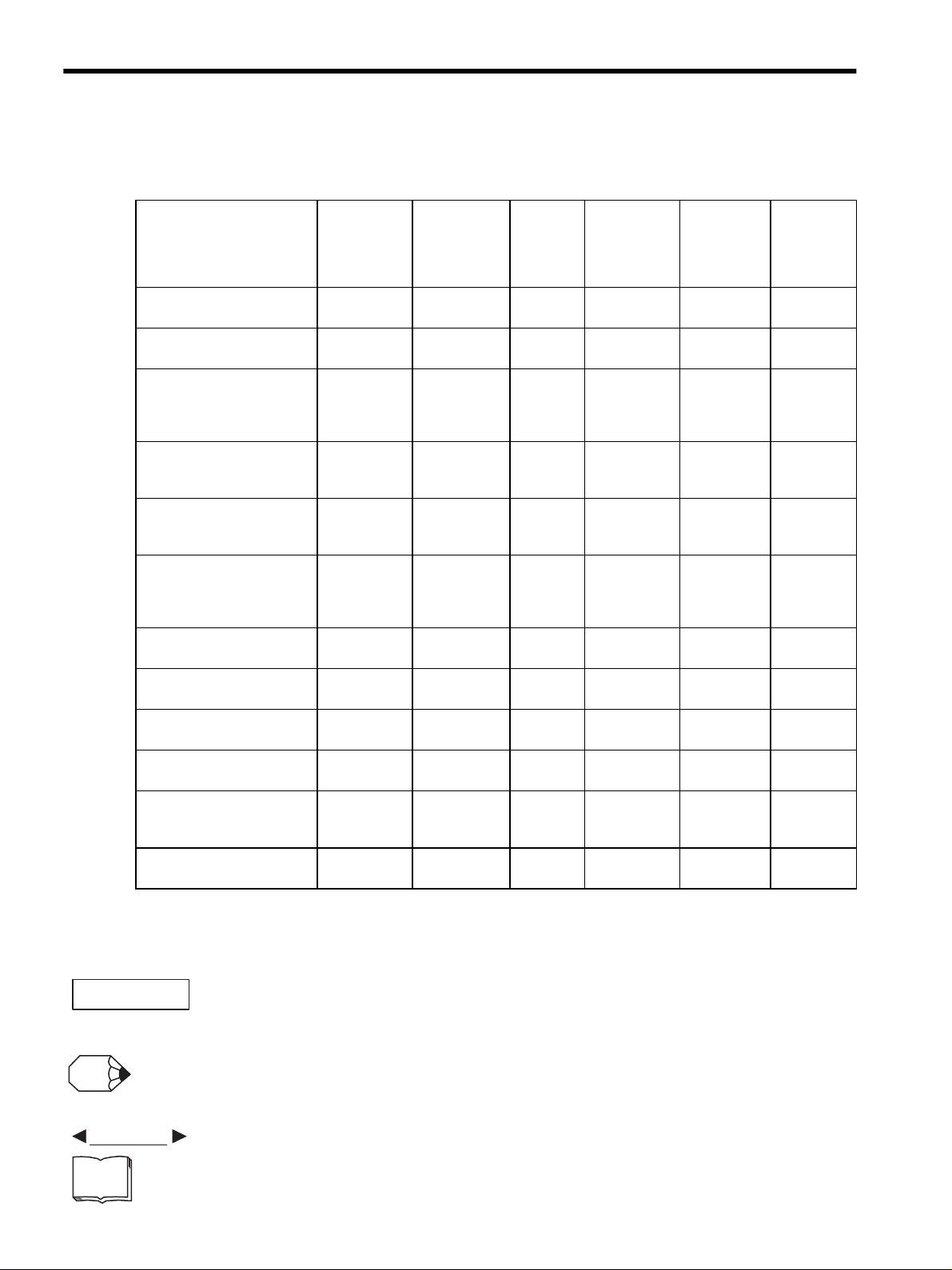
Quick access to your required information
Read the chapters marked with 9 to get the information required for your purpose.
Chapter
Chapter 1
Outline
Chapter 2
Selections
Chapter 3
Linear Servomotor
Specifications and
Dimensional Drawings
Chapter 4
SERVOPACK Specifications
and Dimensional Drawings
Chapter 5
Serial Converter Unit
Specifications and Drawings
Chapter 6
Specifications and Drawings
of Cables and Peripheral
Devices
Chapter 7
Installation and Wiring
Chapter 8
Panel Operator
Chapter 9
Operation
Chapter 10
Adjustment
Chapter 11
Inspection, Maintenance, and
Troubleshooting
Chapter 12
Appendix
SERVOPACK
s, Linear
Servomotors,
and Peripheral
Devices
Ratings and
Characteristics
System
Design
Panel
Configuration
and Wiring
Trial
Operation
and Servo
Adjustment
Inspection
and
Maintenance
9
9
9999
9999
9999
9999
99 9
99
9
9
9
9999
iv
Visual Aids
■
The following aids are used to indicate certain types of information for easier reference.
• Indicates important information that should be memorized, including precautions such as alarm displays to avoid damaging the devices.
• Indicates supplemental information.
• Indicates application examples.
• Indicates definitions of difficult terms or terms that have not been previously explained in this manual.
Page 5
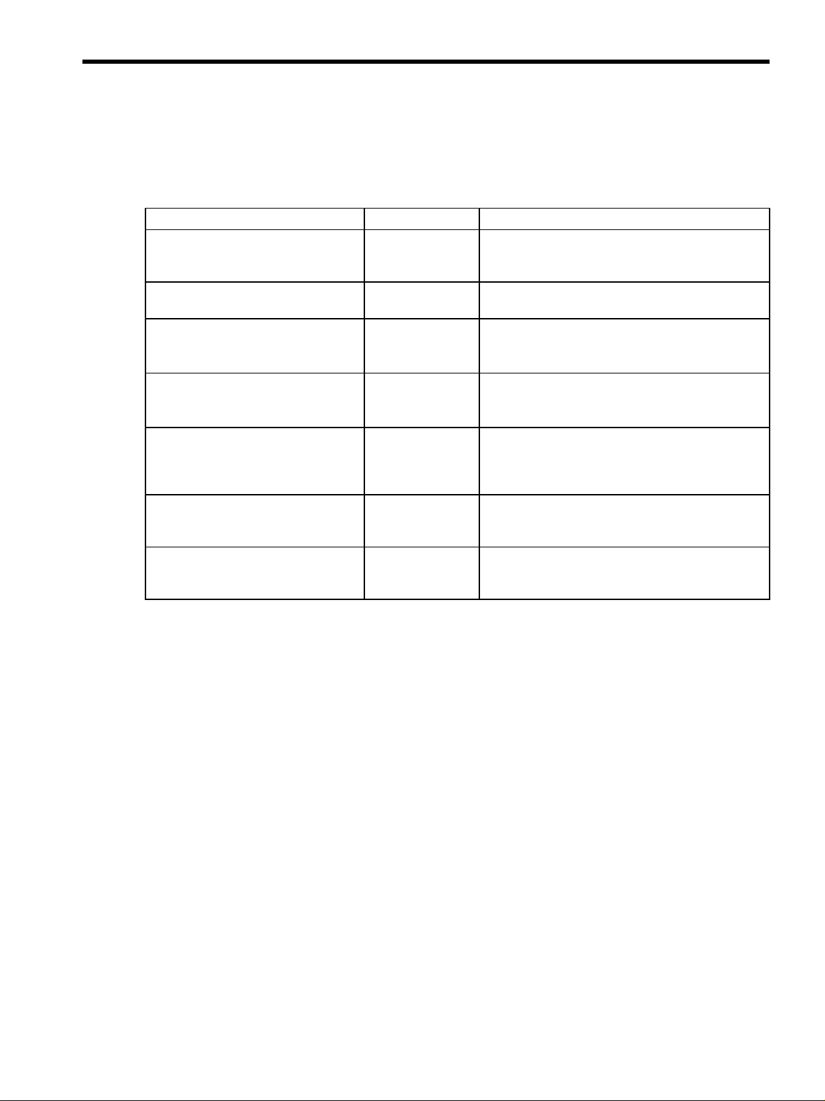
Related Manuals
Refer to the following manuals as required.
Manual Name Manual Number Contents
-II Series
Σ
AC SERVOPACK SGDH/SGDM
SAFETY PRECAUTIONS
-II Series SGMH/SGDM
Σ
Digital Operator Operation Manual
-II Series SGDH MECHATROLINK
Σ
Interface Unit User’s Manual
Model: JUSP-NS100
-II Series SGDH MECHATROLINK-II
Σ
Application Module User’s Manual
Model: JUSP-NS115
-II Series SGDH
Σ
DeviceNet Interface Unit
User’s Manual
Model: JUSP-NS300
-II Series SGDH PROFIBUS-DP
Σ
IF UNIT User’s Manual
Model: JUSP-NS500
-II Series Indexer Application Module
Σ
User’s Manual
Model: JUSP-NS600
TOBPS80000004 Describes the safety precautions on using a SERVO-
TOE-S800-34 Provides detailed information on the operating method
SIE-C718-4 Provides detailed information on MECHATROLINK
SIEPC71080001 Provides detailed information on MECHATROLINK-II
SIE-C718-6 Describes the DeviceNet communications.
SIE-C718-8 Describes the PROFIBUS-DP communications.
SIE-C718-9 Provides detailed information on positioning by com-
PACK in the Σ-
of the JUSP-OP02A-2 digital operator (option).
communications.
communications.
munications and the contact points.
II Series.
v
Page 6
WARNING
CAUTION
PROHIBITED
MANDATORY
Safety Information
The following conventions are used to indicate precautions in this manual. Failure to heed precautions provided
in this manual can result in serious or possibly even fatal injury or damage to the products or to related equipment
and systems.
Indicates precautions that, if not heeded, could possibly result in loss of life or serious
injury.
Indicates precautions that, if not heeded, could result in relatively serious or minor
injury, damage to the product, or faulty operation.
In some situations, the precautions indicated could have serious consequences if not heeded.
Indicates prohibited actions that must not be performed. For example, this symbol
would be used as follows to indicate that fire is prohibited: .
Indicates compulsory actions that must be performed. For example, this symbol would
be used as follows to indicate that grounding is compulsory: .
The warning symbols for ISO and JIS standards are different, as shown below.
ISO JIS
The ISO symbol is used in this manual.
Both of these symbols appear on warning labels on Yaskawa products. Please abide by these warning labels
regardless of which symbol is used.
vi
Page 7
Notes for Safe Operation
WARNING
Read this manual thoroughly before checking products on delivery, storage and transportation, installation,
wiring, operation and inspection, and disposal of the AC servodrive.
• If you have a pacemaker or any other electronic medical device, do not go near the magnetic
way of the linear servomotor.
Failure to observe this warning may result in the malfunction of the medical device.
• Be sure to use nonmagnetic tools when installing or working close to the linear servomotor.
(Example: a beryllium-copper alloy hexagonal wrench set, made by NGK Insulators, Ltd.)
• If starting an operation with the linear servomotor in a machine, set the linear servomotor to
always allow emergency stops.
Failure to observe this warning may result in injury.
• Never touch the linear servomotor or machinery during operation.
Failure to observe this warning may result in injury.
• Before wiring, install the SERVOPACK and the linear servomotor.
Failure to observe this warning may result in electric shock.
• Do not operate switches with wet hands.
Failure to observe this warning may result in electric shock.
• Never touch the inside of the SERVOPACKs.
Failure to observe this warning may result in electric shock.
• Do not touch terminals for five minutes after the power is turned OFF.
Residual voltage may cause electric shock.
• Do not touch terminals for five minutes after voltage resistance test.
Residual voltage may cause electric shock.
• Make sure that the main circuit power cable, the control power cable, and the linear
servomotor main circuit cable are wired correctly.
Failure to observe this warning may result in damage to the SERVOPACK.
• Follow the procedures and instructions for trial operation precisely as described in this manual.
Malfunctions that occur after the servomotor is connected to the equipment not only damage the
equipment, but may also cause an accident resulting in death or injury.
• The SGDH SERVOPACK supports both AC and DC power. If DC power is supplied to the
SERVOPACK without setting Pn001=n.1 (DC power input), the internal components
of the SERVOPACK will burn and may result in fire or serious damage.
Before using a DC power supply, be sure to check the parameter Pn001 setting.
• Do not remove the front cover, cables, connectors, or optional items while the power is ON.
Failure to observe this warning may result in electric shock.
• Do not damage, press, exert excessive force or place heavy objects on the cables.
Failure to observe this warning may result in electric shock, stopping operation of the product, or
burning.
vii
Page 8
WARNING
CAUTION
CAUTION
• Provide an appropriate stopping device on the machine side to ensure safety.
Failure to observe this warning may result in injury.
• Do not come close to the machine immediately after resetting momentary power loss to avoid an
unexpected restart. Take appropriate measures to ensure safety against an unexpected restart.
Failure to observe this warning may result in injury.
• Connect the ground terminal to electrical codes (ground resistance: 100 Ω or less).
Improper grounding may result in electric shock or fire.
• Installation, disassembly, or repair must be performed only by authorized personnel.
Failure to observe this warning may result in electric shock or injury.
• Do not modify the product.
Failure to observe this warning may result in injury or damage to the product.
Checking on Delivery
• Always use the linear servomotor and SERVOPACK in one of the specified combinations.
Failure to observe this caution may result in fire or malfunction.
Storage and Transportation
• Be sure to store the magnetic way of the linear servomotor in the same way as it was originally packaged.
• Do not store or install the product in the following places.
• Locations subject to direct sunlight.
• Locations subject to temperatures outside the range specified in the storage or installation temperature conditions.
• Locations subject to humidity outside the range specified in the storage or installation humidity conditions.
• Locations subject to condensation as the result of extreme changes in temperature.
• Locations subject to corrosive or flammable gases.
• Locations subject to dust, salts, or iron dust.
• Locations subject to exposure to water, oil, or chemicals.
• Locations subject to shock or vibration.
Failure to observe this caution may result in fire, electric shock, or damage to the product.
• Do not carry the linear servomotor by its cables.
Failure to observe this caution may result in injury or malfunction.
• Do not place any load exceeding the limit specified on the packing box.
Failure to observe this caution may result in injury or malfunction.
viii
Page 9
Installation
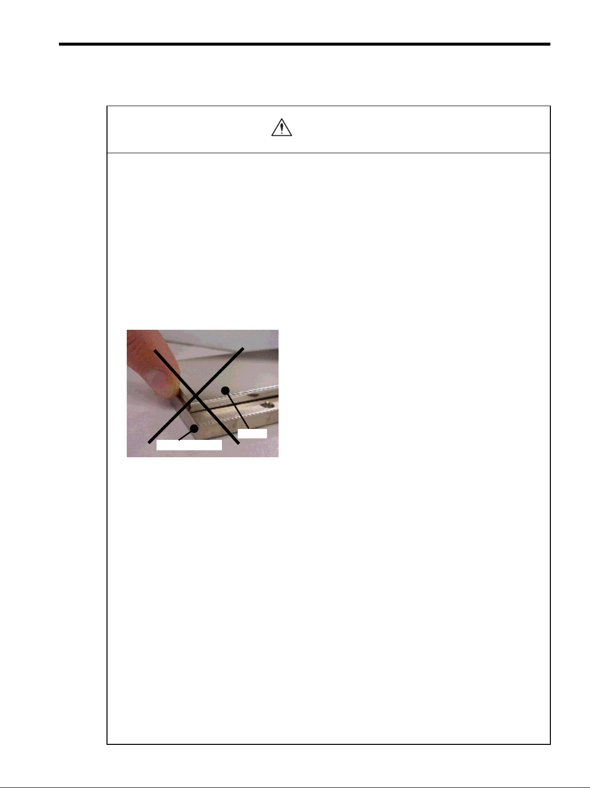
CAUTION
Cover
Magnetic way
• When unpacking and installing magnetic way, check that no metal fragments or magnetized objects near
the stator because they may be affected by the magnetic attraction of the magnetic way.
Failure to observe this caution may result in injury or damage to the magnetic way's magnets.
• Do not use the magnetic way near metal or other magnetized objects.
Failure to observe this caution may result in injury.
• Do not place clocks, magnetic cards, floppy disks, or measuring instruments close to the magnetic way.
Failure to observe this caution may result in malfunction or damage to these items by the magnetic force.
• Securely mount the linear servomotor on to the machine.
If the linear servomotor is not mounted securely, it may loosen during operation.
• Do not carry the magnetic way by its magnet protection cover.
Failure to observe this caution may result in injury by the cover’s edge or the shape of the cover may become distorted.
• When removing the dummy plate for reducing magnetic force used for the SGLFM magnetic way, pay
attention to the magnetic attraction of the magnetic way. Do not place the removed plate close to the
magnetic way.
Failure to observe this caution may result in injury or damage to the magnetic way’s magnets or the magnet protection
cover.
• Install SERVOPACKs, linear servomotors, and regenerative resistors on nonflammable objects.
Mounting directly onto or near flammable objects may result in fire.
• Never use the products in an environment subject to water, corrosive gases, inflammable gases, or
combustibles.
Failure to observe this caution may result in electric shock or fire.
• Do not step on or place a heavy object on the product.
Failure to observe this caution may result in injury.
• Do not cover the inlet or outlet parts and prevent any foreign objects from entering the product.
Failure to observe this caution may cause internal elements to deteriorate resulting in malfunction or fire.
• Be sure to install the product in the correct direction.
Failure to observe this caution may result in malfunction.
• Provide the specified clearances between the SERVOPACK and the control panel or with other devices.
Failure to observe this caution may result in fire or malfunction.
• Do not apply any strong impact.
Failure to observe this caution may result in malfunction.
ix
Page 10
CAUTION
Wiring
• Securely tighten the cable connector screws and securing mechanism.
If the connector screws and securing mechanism are not secure, they may loosen during operation.
• Use power lines and cables with a radius, heat resistance, and flexibility suitable for the system.
• If the SERVOPACK malfunctions, turn OFF the main circuit’s power supply of the SERVOPACK.
The continuous flow of a large current may cause fire.
• Use a noise filter to minimize the effects of electromagnetic damage.
Failure to observe this caution may result in electromagnetic damage to electronic devices used near the SERVOPA CK .
• Do not connect a three-phase power supply to the U, V, or W output terminals.
Failure to observe this caution may result in injury or fire.
• Securely connect the power supply terminals and motor output terminals.
Failure to observe this caution may result in fire.
• Do not bundle or run power and signal lines together in the same duct. Keep power and signal lines
separated by at least 30 cm (11.81 in).
Failure to observe this caution may result in malfunction.
• Use shielded twisted-pair wire or shielded multi-core twisted-pair wire for the signal lines and feedback lines
of the serial converter unit (SC).
The maximum wiring length is 3 m for the reference input line and 20 m for the SC feedback line.
• Do not touch the power terminals for five minutes after turning power OFF because high voltage may still
remain in the SERVOPACK.
Make sure the charge indicator is turned OFF first before starting an inspection.
• Avoid frequently turning power ON and OFF. Do not turn power ON or OFF more than once per minute.
Since the SERVOPACK has a capacitor in the power supply, a high charging current flows for 0.2 seconds when
power is turned ON. Frequently turning power ON and OFF causes main power devices such as capacitors and fuses
to deteriorate, resulting in unexpected problems.
• Observe the following precautions when wiring main circuit terminal blocks.
• Remove the terminal block from the SERVOPACK prior to wiring.
• Insert only one wire per terminal on the terminal block.
• Make sure that the core wire is not electrically shorted to adjacent core wires.
• Do not connect the SERVOPACK for 100 V and 200 V directly to a voltage of 400 V.
The SERVOPACK will be destroyed.
• Be sure to wire correctly and securely.
Failure to observe this caution may result in motor overrun, injury, or malfunction.
• Always use the specified power supply voltage.
An incorrect voltage may result in burning.
• Make sure that the polarity is correct.
Incorrect polarity may cause ruptures or damage.
• Take appropriate measures to ensure that the input power supply is supplied within the specified voltage
fluctuation range. Be particularly careful in places where the power supply is unstable.
An incorrect power supply may result in damage to the product.
x
Page 11
• Install external breakers or other safety devices against short-circuiting in external wiring.
CAUTION
CAUTION
Failure to observe this caution may result in fire.
• Take appropriate and sufficient countermeasures for each when installing systems in the following
locations.
• Locations subject to static electricity or other forms of noise.
• Locations subject to strong electromagnetic fields and magnetic fields.
• Locations subject to possible exposure to radioactivity.
• Locations close to power supplies including power supply lines.
Failure to observe this caution may result in damage to the product.
Operation
• Do not stand within the machine's range of motion during operation.
Failure to observe this caution may result in injury.
• Before operation, install a limit switch or stopper on the end of the slider to prevent unexpected movement.
Failure to observe this caution may result in injury.
• Before starting operation with a machine connected, change the settings to match the parameters of the
machine.
Starting operation without matching the proper settings may cause the machine to run out of control or malfunction.
• Forward run prohibited (P-OT) and reverse run prohibited (N-OT) signals are not effective during zero point
search mode using parameter Fn003.
• If using the linear servomotor on a vertical axis, install a safety device such as a counterbalance so that the
workpiece does not fall if an alarm or overtravel occurs. Set the linear servomotor so that it will stop in the
zero clamp state at occurrence of overtravel.
The workpiece may fall during overtraveling.
• When not using the online autotuning, set to the correct mass ratio.
Setting to an incorrect moment of inertia ratio may cause vibration.
• Do not touch the SERVOPACK heatsinks, regenerative resistor, or servomotor while power is ON or soon
after the power is turned OFF.
Failure to observe this caution may result in burns due to high temperatures.
• Do not make any extreme adjustments or setting changes of parameters.
Failure to observe this caution may result in injury due to unstable operation.
• When an alarm occurs, remove the cause, reset the alarm after confirming safety, and then resume
operation.
Failure to observe this caution may result in injury.
xi
Page 12
CAUTION
CAUTION
Maintenance and Inspection
• When replacing the SERVOPACK, transfer the previous SERVOPACK parameters to the new
SERVOPACK before resuming operation.
Failure to observe this caution may result in damage to the product.
• Do not attempt to change wiring while the power is ON.
Failure to observe this caution may result in electric shock or injury.
• Do not disassemble the linear servomotor.
Failure to observe this caution may result in electric shock or injury.
Disposal
• When disposing of the products, treat them as ordinary industrial waste.
General Precautions
Note the following to ensure safe application.
• The drawings presented in this manual are sometimes shown without covers or protective guards. Always replace
the cover or protective guard as specified first, and then operate the products in accordance with the manual.
• The drawings presented in this manual are typical examples and may not match the product you received.
• This manual is subject to change due to product improvement, specification modification, and manual
improvement. When this manual is revised, the manual code is updated and the new manual is published as a next
edition.
• If the manual must be ordered due to loss or damage, inform your nearest Yaskawa representative or one of the
offices listed on the back of this manual.
• Yaskawa will not take responsibility for the results of unauthorized modifications of this product. Yaskawa shall
not be liable for any damages or troubles resulting from unauthorized modification.
xii
Page 13

CONTENTS
About this Manual - - - - - - - - - - - - - - - - - - - - - - - - - - - - - - - - - - - - - - - - - - - - - - - - - - - - - - - iii
Related Manuals - - - - - - - - - - - - - - - - - - - - - - - - - - - - - - - - - - - - - - - - - - - - - - - - - - - - - - - - v
Safety Information - - - - - - - - - - - - - - - - - - - - - - - - - - - - - - - - - - - - - - - - - - - - - - - - - - - - - - - vi
Notes for Safe Operation - - - - - - - - - - - - - - - - - - - - - - - - - - - - - - - - - - - - - - - - - - - - - - - - - - vii
1
Outline
1.1 Checking Products - - - - - - - - - - - - - - - - - - - - - - - - - - - - - - - - - - - - - - - - - - - - 1-2
1.1.1 Check Items - - - - - - - - - - - - - - - - - - - - - - - - - - - - - - - - - - - - - - - - - - - - - - - - - - - - - - - - - - 1-2
1.1.2 Linear Servomotors - - - - - - - - - - - - - - - - - - - - - - - - - - - - - - - - - - - - - - - - - - - - - - - - - - - - - 1-2
1.1.3 SERVOPACKs - - - - - - - - - - - - - - - - - - - - - - - - - - - - - - - - - - - - - - - - - - - - - - - - - - - - - - - - 1-3
1.1.4 Serial Converter Units - - - - - - - - - - - - - - - - - - - - - - - - - - - - - - - - - - - - - - - - - - - - - - - - - - - 1-4
1.2 Product Part Names - - - - - - - - - - - - - - - - - - - - - - - - - - - - - - - - - - - - - - - - - - - 1-5
1.2.1 Linear Servomotors - - - - - - - - - - - - - - - - - - - - - - - - - - - - - - - - - - - - - - - - - - - - - - - - - - - - - 1-5
1.2.2 SERVOPACKs - - - - - - - - - - - - - - - - - - - - - - - - - - - - - - - - - - - - - - - - - - - - - - - - - - - - - - - - 1-6
1.3 Examples of Servo System Configurations - - - - - - - - - - - - - - - - - - - - - - - - - - - 1-8
1.3.1 Single-phase, 200 V Main Circuit - - - - - - - - - - - - - - - - - - - - - - - - - - - - - - - - - - - - - - - - - - - 1-8
1.3.2 Three-phase, 200 V Main Circuit- - - - - - - - - - - - - - - - - - - - - - - - - - - - - - - - - - - - - - - - - - - - 1-9
1.3.3 Three-phase, 400 V Main Circuit- - - - - - - - - - - - - - - - - - - - - - - - - - - - - - - - - - - - - - - - - - - 1-10
1.4 Applicable Standards - - - - - - - - - - - - - - - - - - - - - - - - - - - - - - - - - - - - - - - - - 1-11
1.4.1 North American Safety Standards (UL, CSA) - - - - - - - - - - - - - - - - - - - - - - - - - - - - - - - - - - 1-11
1.4.2 CE Marking- - - - - - - - - - - - - - - - - - - - - - - - - - - - - - - - - - - - - - - - - - - - - - - - - - - - - - - - - - 1-11
2
Selections
2.1 Linear Servomotor Model Designation - - - - - - - - - - - - - - - - - - - - - - - - - - - - - - 2-2
2.1.1 Coil Assembly - - - - - - - - - - - - - - - - - - - - - - - - - - - - - - - - - - - - - - - - - - - - - - - - - - - - - - - - 2-2
2.1.2 Magnetic Way - - - - - - - - - - - - - - - - - - - - - - - - - - - - - - - - - - - - - - - - - - - - - - - - - - - - - - - - 2-2
2.2 SERVOPACK Model Designation - - - - - - - - - - - - - - - - - - - - - - - - - - - - - - - - - - 2-3
2.3 Σ-II Series SERVOPACKs and Applicable Linear Servomotors
2.4 Serial Converter Units Models - - - - - - - - - - - - - - - - - - - - - - - - - - - - - - - - - - - - 2-6
2.5 Selecting Cables - - - - - - - - - - - - - - - - - - - - - - - - - - - - - - - - - - - - - - - - - - - - - 2-7
2.6 Selecting Peripheral Devices - - - - - - - - - - - - - - - - - - - - - - - - - - - - - - - - - - - - - 2-9
2.6.1 Special Options- - - - - - - - - - - - - - - - - - - - - - - - - - - - - - - - - - - - - - - - - - - - - - - - - - - - - - - - 2-9
2.6.2 Molded-case Circuit Breaker and Fuse Capacity - - - - - - - - - - - - - - - - - - - - - - - - - - - - - - - 2-11
2.6.3 Noise Filters and DC Reactors - - - - - - - - - - - - - - - - - - - - - - - - - - - - - - - - - - - - - - - - - - - - 2-12
- - - - - - - - - - - - 2-4
xiii
Page 14

2.6.4 Regenerative Resistors- - - - - - - - - - - - - - - - - - - - - - - - - - - - - - - - - - - - - - - - - - - - - - - - - -2-13
2.6.5 Linear Scales - - - - - - - - - - - - - - - - - - - - - - - - - - - - - - - - - - - - - - - - - - - - - - - - - - - - - - - - 2-14
3
Specifications and Dimensional Drawings
3.1 Ratings and Specifications of SGLGW/SGLGM- - - - - - - - - - - - - - - - - - - - - - - - 3-2
3.2 Ratings and Specifications of SGLFW/SGLFM - - - - - - - - - - - - - - - - - - - - - - - - 3-6
3.3 Ratings and Specifications of SGLTW/SGLTM- - - - - - - - - - - - - - - - - - - - - - - - - 3-9
3.4 Mechanical Specifications of Linear Servomotors - - - - - - - - - - - - - - - - - - - - - 3-15
3.5 Quick Guide to Linear Servomotor Dimensional Drawings - - - - - - - - - - - - - - - 3-16
3.6 Dimensional Drawings of SGLGW/SGLGM Linear Servomotors - - - - - - - - - - - 3-17
3.6.1 SGLG-30 Linear Servomotors- - - - - - - - - - - - - - - - - - - - - - - - - - - - - - - - - - - - - - - - - - - - 3-17
3.6.2 SGLG-40 Linear Servomotors- - - - - - - - - - - - - - - - - - - - - - - - - - - - - - - - - - - - - - - - - - - - 3-19
3.6.3 SGLG-60 Linear Servomotors- - - - - - - - - - - - - - - - - - - - - - - - - - - - - - - - - - - - - - - - - - - - 3-22
3.6.4 SGLG-90 Linear Servomotors- - - - - - - - - - - - - - - - - - - - - - - - - - - - - - - - - - - - - - - - - - - - 3-25
3.7 Dimensional Drawings of SGLFW/SGLFM Linear Servomotors - - - - - - - - - - - 3-27
3.7.1 SGLF-20 Linear Servomotors - - - - - - - - - - - - - - - - - - - - - - - - - - - - - - - - - - - - - - - - - - - - 3-27
3.7.2 SGLF-35 Linear Servomotors - - - - - - - - - - - - - - - - - - - - - - - - - - - - - - - - - - - - - - - - - - - - 3-29
3.7.3 SGLF-50 Linear Servomotors - - - - - - - - - - - - - - - - - - - - - - - - - - - - - - - - - - - - - - - - - - - - 3-31
3.7.4 SGLF-1Z Linear Servomotors - - - - - - - - - - - - - - - - - - - - - - - - - - - - - - - - - - - - - - - - - - - - 3-33
3.8 Dimensional Drawings of SGLTW / SGLTM Linear Servomotors - - - - - - - - - - - 3-35
3.8.1 SGLT-20 Linear Servomotors - - - - - - - - - - - - - - - - - - - - - - - - - - - - - - - - - - - - - - - - - - - - 3-35
3.8.2 SGLT-35A Linear Servomotors- - - - - - - - - - - - - - - - - - - - - - - - - - - - - - - - - - - - 3-38
3.8.3 SGLT-35H Linear Servomotors- - - - - - - - - - - - - - - - - - - - - - - - - - - - - - - - - - - -3-41
3.8.4 SGLT-40 Linear Servomotors - - - - - - - - - - - - - - - - - - - - - - - - - - - - - - - - - - - - - - - - - - - - 3-43
SGLT-50
3.8.5
3.8.6 SGLT-80 Linear Servomotors - - - - - - - - - - - - - - - - - - - - - - - - - - - - - - - - - - - - - - - - - - - - 3-48
Linear Servomotors - - - - - - - - - - - - - - - - - - - - - - - - - - - - - - - - - - - - - - - - - - - - 3-46
4
SERVOPACK Specifications and Dimensional Drawings
4.1 SERVOPACK Ratings and Specifications - - - - - - - - - - - - - - - - - - - - - - - - - - - - 4-2
4.1.1 Single-phase/Three-phase 200 V - - - - - - - - - - - - - - - - - - - - - - - - - - - - - - - - - - - - - - - - - - - -4-2
4.1.2 Three-phase 400 V - - - - - - - - - - - - - - - - - - - - - - - - - - - - - - - - - - - - - - - - - - - - - - - - - - - - - -4-2
4.1.3 SERVOPACK Ratings and Specifications - - - - - - - - - - - - - - - - - - - - - - - - - - - - - - - - - - - - - -4-3
xiv
4.2 SERVOPACK Installation - - - - - - - - - - - - - - - - - - - - - - - - - - - - - - - - - - - - - - - 4-5
4.3 SERVOPACK Internal Block Diagrams - - - - - - - - - - - - - - - - - - - - - - - - - - - - - - 4-7
4.3.1 Single-phase 200 V, 50 W to 400 W Models - - - - - - - - - - - - - - - - - - - - - - - - - - - - - - - - - - - -4-7
4.3.2 Three-phase 200 V, 500 W to 1.5 kW Models - - - - - - - - - - - - - - - - - - - - - - - - - - - - - - - - - - -4-8
4.3.3 Three-phase 200 V, 2.0 kW to 5.0 kW Models - - - - - - - - - - - - - - - - - - - - - - - - - - - - - - - - - - -4-8
Page 15

4.3.4 Three-phase 200 V, 7.5 kW Models- - - - - - - - - - - - - - - - - - - - - - - - - - - - - - - - - - - - - - - - - - 4-9
4.3.5 Three-phase 400 V, 500 W to 3.0 kW Models- - - - - - - - - - - - - - - - - - - - - - - - - - - - - - - - - - - 4-9
4.3.6 Three-phase 400 V, 5.0 kW Model - - - - - - - - - - - - - - - - - - - - - - - - - - - - - - - - - - - - - - - - - 4-10
4.3.7 Three-phase 400 V, 7.5 kW Models- - - - - - - - - - - - - - - - - - - - - - - - - - - - - - - - - - - - - - - - - 4-10
4.4 SERVOPACK’s Power Supply Capacities and Power Losses - - - - - - - - - - - - - 4-11
4.5 SERVOPACK Overload Characteristics and Allowable Load Mass - - - - - - - - - 4-12
4.5.1 Overload Characteristics - - - - - - - - - - - - - - - - - - - - - - - - - - - - - - - - - - - - - - - - - - - - - - - - 4-12
4.5.2 Starting Time and Stopping Time- - - - - - - - - - - - - - - - - - - - - - - - - - - - - - - - - - - - - - - - - - - 4-13
4.6 SERVOPACK Dimensional Drawings - - - - - - - - - - - - - - - - - - - - - - - - - - - - - - 4-14
4.7 Dimensional Drawings of Base-mounted SERVOPACK Model - - - - - - - - - - - - 4-15
4.7.1 Single-phase 200 V: 50 W/100 W/200 W (A5AE/01AE/02AE) - - - - - - - - - - - - - - - - - - - - - - 4-15
4.7.2 Single-phase 200 V: 400 W (04AE) - - - - - - - - - - - - - - - - - - - - - - - - - - - - - - - - - - - - - - - - - 4-16
4.7.3 Three-phase 200 V: 500 W/750 W/1.0 kW (05AE/08AE/10AE) - - - - - - - - - - - - - - - - - - - - - 4-17
4.7.4 Three-phase 200 V: 1.5 kW (15AE)
Three-phase 400 V: 500 W/750 W/1.0 kW/1.5 kW (05DE/08DE/10DE/15DE) - - - - - - - - - - - 4-18
4.7.5 Three-phase 200 V: 2.0 kW/3.0 kW (20AE/30AE)
Three-phase 400 V: 2.0 kW/3.0 kW (20DE/30DE) - - - - - - - - - - - - - - - - - - - - - - - - - - - - - - 4-19
4.7.6 Three-phase 200 V: 5.0 kW (50AE)
Three-phase 400 V: 5.0 kW (50DE) - - - - - - - - - - - - - - - - - - - - - - - - - - - - - - - - - - - - - - - - 4-20
4.7.7 Three-phase 200 V: 7.5 kW (75AE)- - - - - - - - - - - - - - - - - - - - - - - - - - - - - - - - - - - - - - - - - 4-21
4.7.8 Three-phase 400 V: 7.5 kW (75DE)- - - - - - - - - - - - - - - - - - - - - - - - - - - - - - - - - - - - - - - - - 4-22
5
Specifications and Dimensional
Drawings of Serial Converter Unit
5.1 Serial Converter Unit Specifications - - - - - - - - - - - - - - - - - - - - - - - - - - - - - - - - 5-2
5.2 Analog Signal Input Timing - - - - - - - - - - - - - - - - - - - - - - - - - - - - - - - - - - - - - - 5-3
5.3 Dimensional Drawings of Serial Converter Unit - - - - - - - - - - - - - - - - - - - - - - - - 5-4
5.3.1 Linear Scale with Cable for Hall Sensor by Heidenhain - - - - - - - - - - - - - - - - - - - - - - - - - - - - 5-4
5.3.2 Linear Scale with Cable for Hall Sensor by Renishaw - - - - - - - - - - - - - - - - - - - - - - - - - - - - - 5-6
6
Specifications and Dimensional
Drawings of Cables and
Peripheral Devices
6.1 Linear Servomotor Main Circuit Cables- - - - - - - - - - - - - - - - - - - - - - - - - - - - - - 6-2
6.2 Cables for Connecting Serial Converter Units - - - - - - - - - - - - - - - - - - - - - - - - - 6-7
6.3 Cables for Connecting Linear Scales - - - - - - - - - - - - - - - - - - - - - - - - - - - - - - - 6-8
6.4 Cables for Connecting Hall Sensors - - - - - - - - - - - - - - - - - - - - - - - - - - - - - - - - 6-9
xv
Page 16

6.5 Flexible Cables- - - - - - - - - - - - - - - - - - - - - - - - - - - - - - - - - - - - - - - - - - - - - - 6-10
6.6 SERVOPACK Main Circuit Wire Size - - - - - - - - - - - - - - - - - - - - - - - - - - - - - - 6-12
6.6.1 Cable Types- - - - - - - - - - - - - - - - - - - - - - - - - - - - - - - - - - - - - - - - - - - - - - - - - - - - - - - - - -6-12
6.6.2 Single-phase 200 V - - - - - - - - - - - - - - - - - - - - - - - - - - - - - - - - - - - - - - - - - - - - - - - - - - - -6-13
6.6.3 Three-phase 200 V - - - - - - - - - - - - - - - - - - - - - - - - - - - - - - - - - - - - - - - - - - - - - - - - - - - - -6-13
6.6.4 Three-phase 400 V - - - - - - - - - - - - - - - - - - - - - - - - - - - - - - - - - - - - - - - - - - - - - - - - - - - - -6-14
6.7 I/O Signal Cables for CN1 Connector - - - - - - - - - - - - - - - - - - - - - - - - - - - - - - 6-15
6.7.1 Standard Cables- - - - - - - - - - - - - - - - - - - - - - - - - - - - - - - - - - - - - - - - - - - - - - - - - - - - - - -6-15
6.7.2 Connector Type and Cable Size- - - - - - - - - - - - - - - - - - - - - - - - - - - - - - - - - - - - - - - - - - - - 6-15
6.7.3 Connection Diagram - - - - - - - - - - - - - - - - - - - - - - - - - - - - - - - - - - - - - - - - - - - - - - - - - - - -6-17
6.8 Peripheral Devices - - - - - - - - - - - - - - - - - - - - - - - - - - - - - - - - - - - - - - - - - - - 6-18
6.8.1 Cables for Connecting Personal Computers - - - - - - - - - - - - - - - - - - - - - - - - - - - - - - - - - - - 6-18
6.8.2 Digital Operator - - - - - - - - - - - - - - - - - - - - - - - - - - - - - - - - - - - - - - - - - - - - - - - - - - - - - - - 6-18
6.8.3 Cables for Analog Monitor - - - - - - - - - - - - - - - - - - - - - - - - - - - - - - - - - - - - - - - - - - - - - - - -6-19
6.8.4 Connector Terminal Block Converter Unit - - - - - - - - - - - - - - - - - - - - - - - - - - - - - - - - - - - - - 6-20
6.8.5 External Regenerative Resistor - - - - - - - - - - - - - - - - - - - - - - - - - - - - - - - - - - - - - - - - - - - - 6-21
6.8.6 Regenerative Resistor- - - - - - - - - - - - - - - - - - - - - - - - - - - - - - - - - - - - - - - - - - - - - - - - - - -6-22
6.8.7 Molded-case Circuit Breaker (MCCB) - - - - - - - - - - - - - - - - - - - - - - - - - - - - - - - - - - - - - - - -6-23
6.8.8 Noise Filter - - - - - - - - - - - - - - - - - - - - - - - - - - - - - - - - - - - - - - - - - - - - - - - - - - - - - - - - - -6-24
6.8.9 DC Reactor for Harmonic Suppression - - - - - - - - - - - - - - - - - - - - - - - - - - - - - - - - - - - - - - -6-28
6.8.10 MECHATROLINK application module - - - - - - - - - - - - - - - - - - - - - - - - - - - - - - - - - - - - - - -6-30
6.8.11 DeviceNet application module - - - - - - - - - - - - - - - - - - - - - - - - - - - - - - - - - - - - - - - - - - - -6-31
6.8.12 PROFIBUS-DP application module- - - - - - - - - - - - - - - - - - - - - - - - - - - - - - - - - - - - - - - - - 6-32
6.8.13 INDEXER application module - - - - - - - - - - - - - - - - - - - - - - - - - - - - - - - - - - - - - - - - - - - -6-34
xvi
7
Wiring
7.1 Linear Servomotor Installation - - - - - - - - - - - - - - - - - - - - - - - - - - - - - - - - - - - - 7-2
7.1.1 Introduction - - - - - - - - - - - - - - - - - - - - - - - - - - - - - - - - - - - - - - - - - - - - - - - - - - - - - - - - - - -7-2
7.1.2 SGLGW and SGLGM Linear Servomotors (Coreless Types)- - - - - - - - - - - - - - - - - - - - - - - - -7-4
7.1.3 SGLFW and SGLFM Linear Servomotor (F-shaped with Core) - - - - - - - - - - - - - - - - - - - - - - -7-7
7.1.4 SGLTW and SGLTM Linear Servomotor (T Type with Iron Core) - - - - - - - - - - - - - - - - - - - - - 7-11
7.2 Wiring Main Circuit - - - - - - - - - - - - - - - - - - - - - - - - - - - - - - - - - - - - - - - - - - - 7-16
7.2.1 Names and Functions of Main Circuit Terminals - - - - - - - - - - - - - - - - - - - - - - - - - - - - - - - -7-16
7.2.2 Wiring Main Circuit Power Supply Connector (Spring Type) - - - - - - - - - - - - - - - - - - - - - - - -7-18
7.2.3 Typical Main Circuit Wiring Examples - - - - - - - - - - - - - - - - - - - - - - - - - - - - - - - - - - - - - - - - 7-19
7.3 Wiring Encoders- - - - - - - - - - - - - - - - - - - - - - - - - - - - - - - - - - - - - - - - - - - - - 7-22
7.3.1 Connecting an Encoder (CN2) and Output Signals from the SERVOPACK- - - - - - - - - - - - - - 7-22
7.3.2 Encoder Connector (CN2) Terminal Layout - - - - - - - - - - - - - - - - - - - - - - - - - - - - - - - - - - - -7-22
7.4 Examples of I/O Signal Connections - - - - - - - - - - - - - - - - - - - - - - - - - - - - - - 7-23
7.4.1 Speed Control Mode - - - - - - - - - - - - - - - - - - - - - - - - - - - - - - - - - - - - - - - - - - - - - - - - - - - -7-23
Page 17

7.4.2 Position Control Mode - - - - - - - - - - - - - - - - - - - - - - - - - - - - - - - - - - - - - - - - - - - - - - - - - - 7-24
7.4.3 Force Control Mode- - - - - - - - - - - - - - - - - - - - - - - - - - - - - - - - - - - - - - - - - - - - - - - - - - - - 7-25
7.4.4 I/O Signal Connector (CN1) Terminal Layout - - - - - - - - - - - - - - - - - - - - - - - - - - - - - - - - - - 7-26
7.4.5 I/O Signal (CN1) Names and Functions - - - - - - - - - - - - - - - - - - - - - - - - - - - - - - - - - - - - - - 7-27
7.4.6 Interface Circuit- - - - - - - - - - - - - - - - - - - - - - - - - - - - - - - - - - - - - - - - - - - - - - - - - - - - - - - 7-29
7.5 Others - - - - - - - - - - - - - - - - - - - - - - - - - - - - - - - - - - - - - - - - - - - - - - - - - - - - 7-32
7.5.1 Wiring Precautions - - - - - - - - - - - - - - - - - - - - - - - - - - - - - - - - - - - - - - - - - - - - - - - - - - - - 7-32
7.5.2 Wiring for Noise Control - - - - - - - - - - - - - - - - - - - - - - - - - - - - - - - - - - - - - - - - - - - - - - - - - 7-33
7.5.3 Using More Than One SERVOPACK- - - - - - - - - - - - - - - - - - - - - - - - - - - - - - - - - - - - - - - - 7-36
7.5.4 Operating Conditions on 400-V Power Supply Voltage - - - - - - - - - - - - - - - - - - - - - - - - - - - 7-37
7.5.5 DC Reactor for Harmonic Suppression - - - - - - - - - - - - - - - - - - - - - - - - - - - - - - - - - - - - - - 7-38
7.6 Connecting Regenerative Resistors - - - - - - - - - - - - - - - - - - - - - - - - - - - - - - - 7-39
7.6.1 Regenerative Power and Regenerative Resistance - - - - - - - - - - - - - - - - - - - - - - - - - - - - - 7-39
7.6.2 Connecting External Regenerative Resistors - - - - - - - - - - - - - - - - - - - - - - - - - - - - - - - - - - 7-39
8
Digital Operator/Panel Operator
8.1 Functions on Digital Operator/Panel Operator - - - - - - - - - - - - - - - - - - - - - - - - - 8-2
8.1.1 Connecting the Digital Operator - - - - - - - - - - - - - - - - - - - - - - - - - - - - - - - - - - - - - - - - - - - 8-2
8.1.2 Key Names and Functions - - - - - - - - - - - - - - - - - - - - - - - - - - - - - - - - - - - - - - - - - - - - - - - 8-3
8.1.3 Basic Mode Selection and Operation- - - - - - - - - - - - - - - - - - - - - - - - - - - - - - - - - - - - - - - - - 8-4
8.1.4 Status Display - - - - - - - - - - - - - - - - - - - - - - - - - - - - - - - - - - - - - - - - - - - - - - - - - - - - - - - - 8-6
8.2 Operation in Utility Function Mode (Fn) - - - - - - - - - - - - - - - - - - - - - - - - - 8-8
8.2.1 List of Utility Function Modes - - - - - - - - - - - - - - - - - - - - - - - - - - - - - - - - - - - - - - - - - - - - - - 8-8
8.2.2 Alarm Traceback Data Display (Fn000) - - - - - - - - - - - - - - - - - - - - - - - - - - - - - - - - - - - - - - - 8-9
8.2.3 JOG Mode Operation (Fn002) - - - - - - - - - - - - - - - - - - - - - - - - - - - - - - - - - - - - - - - - - - - - 8-10
8.2.4 Zero-point Search Mode (Fn003) - - - - - - - - - - - - - - - - - - - - - - - - - - - - - - - - - - - - - - - - - - 8-11
8.2.5 Parameter Settings Initialization (Fn005) - - - - - - - - - - - - - - - - - - - - - - - - - - - - - - - - - - - - - 8-12
8.2.6 Alarm Traceback Data Clear (Fn006) - - - - - - - - - - - - - - - - - - - - - - - - - - - - - - - - - - - - - - - 8-13
8.2.7 Automatic Offset-adjustment of Motor Current Detection Signal (Fn00E) - - - - - - - - - - - - - - 8-14
8.2.8 Manual Offset-adjustment of Motor Current Detection Signal (Fn00F) - - - - - - - - - - - - - - - - 8-15
8.2.9 Password Setting (Protects Parameters from Being Changed) (Fn010) - - - - - - - - - - - - - - - 8-16
8.2.10 Motor Models Display (Fn011) - - - - - - - - - - - - - - - - - - - - - - - - - - - - - - - - - - - - - - - - - - - 8-17
8.2.11 Software Version Display (Fn012) - - - - - - - - - - - - - - - - - - - - - - - - - - - - - - - - - - - - - - - - - 8-18
8.2.12 Application Module Detection Results Clear (Fn014)- - - - - - - - - - - - - - - - - - - - - - - - - - - - 8-19
8.3 Operation in Parameter Setting Mode (Pn) - - - - - - - - - - - - - - - - - - - - - - 8-20
8.3.1 Setting Parameters - - - - - - - - - - - - - - - - - - - - - - - - - - - - - - - - - - - - - - - - - - - - - - - - - - - - 8-20
8.3.2 Input Circuit Signal Allocation - - - - - - - - - - - - - - - - - - - - - - - - - - - - - - - - - - - - - - - - - - - - - 8-24
8.3.3 Output Circuit Signal Allocation- - - - - - - - - - - - - - - - - - - - - - - - - - - - - - - - - - - - - - - - - - - - 8-28
8.4 Operation in Monitor Mode (Un) - - - - - - - - - - - - - - - - - - - - - - - - - - - - - 8-30
8.4.1 List of Monitor Modes - - - - - - - - - - - - - - - - - - - - - - - - - - - - - - - - - - - - - - - - - - - - - - - - - - 8-30
xvii
Page 18

8.4.2 Sequence I/O Signal Monitor Display - - - - - - - - - - - - - - - - - - - - - - - - - - - - - - - - - - - - - - - -8-31
8.4.3 Operation in Monitor Mode - - - - - - - - - - - - - - - - - - - - - - - - - - - - - - - - - - - - - - - - - - - - - - - 8-32
8.4.4 Monitor Display of Reference Pulse Counter and Feedback Pulse Counter - - - - - - - - - - - - -8-33
8.4.5 Allowable Maximum Motor Speed for Dividing Ratio Monitor (For the software version 32 or later)
8-34
8.4.6 Hall Sensor Signal Monitor (For the software version 32 or later) - - - - - - - - - - - - - - - - - - - - 8-35
9
Operation
9.1 Trial Operation - - - - - - - - - - - - - - - - - - - - - - - - - - - - - - - - - - - - - - - - - - - - - - - 9-4
9.2 Trial Operation Using SERVOPACK Internal References - - - - - - - - - - - - - - - - - 9-6
9.2.1 SERVOPACK Setup Procedure - - - - - - - - - - - - - - - - - - - - - - - - - - - - - - - - - - - - - - - - - - - - -9-6
9.2.2 Setup Procedure Using Linear Servomotors with Hall Sensors - - - - - - - - - - - - - - - - - - - - - - -9-6
9.2.3 Setup Procedure Using Linear Servomotors without Hall Sensors - - - - - - - - - - - - - - - - - - - - 9-12
9.3 Trial Operation for Linear Servomotor without Load from Host
Reference - - - - - - - - - - - - - - - - - - - - - - - - - - - - - - - - - - - - - - - - - - - - - - - - - 9-22
9.3.1 Servo ON Command from the Host - - - - - - - - - - - - - - - - - - - - - - - - - - - - - - - - - - - - - - - - - 9-22
9.3.2 Operating Procedure in Speed Control Mode (Pn000 = n.0)- - - - - - - - - - - - - - - - - - - -9-24
9.3.3 Operating Procedure in Position Control Mode (Pn000 = n.1) - - - - - - - - - - - - - - - - - -9-26
Trial Operation with the Linear Servomotor Connected to the Machine
9.4
- - - - - - 9-28
9.5 Control Mode Selection- - - - - - - - - - - - - - - - - - - - - - - - - - - - - - - - - - - - - - - - 9-29
9.6 Setting Common Basic Functions - - - - - - - - - - - - - - - - - - - - - - - - - - - - - - - - 9-30
9.6.1 Setting the Servo ON Signal - - - - - - - - - - - - - - - - - - - - - - - - - - - - - - - - - - - - - - - - - - - - - -9-30
9.6.2 Switching the Linear Servomotor Movement Direction - - - - - - - - - - - - - - - - - - - - - - - - - - - -9-31
9.6.3 Setting the Overtravel Limit Function - - - - - - - - - - - - - - - - - - - - - - - - - - - - - - - - - - - - - - - - 9-32
9.6.4 Selecting the Stopping Method After Servo OFF - - - - - - - - - - - - - - - - - - - - - - - - - - - - - - - - 9-34
9.6.5 Instantaneous Power Loss Settings - - - - - - - - - - - - - - - - - - - - - - - - - - - - - - - - - - - - - - - - - 9-35
9.6.6 Motor Maximum Speed (For the software version 32 or later) - - - - - - - - - - - - - - - - - - - - - - -9-35
9.7 Operating Using Speed Control with Analog Reference - - - - - - - - - - - - - - - - - 9-36
9.7.1 Setting Parameters - - - - - - - - - - - - - - - - - - - - - - - - - - - - - - - - - - - - - - - - - - - - - - - - - - - - - 9-36
9.7.2 Setting Input Signals - - - - - - - - - - - - - - - - - - - - - - - - - - - - - - - - - - - - - - - - - - - - - - - - - - - -9-37
9.7.3 Adjusting Offset - - - - - - - - - - - - - - - - - - - - - - - - - - - - - - - - - - - - - - - - - - - - - - - - - - - - - - - 9-38
9.7.4 Soft Start - - - - - - - - - - - - - - - - - - - - - - - - - - - - - - - - - - - - - - - - - - - - - - - - - - - - - - - - - - - - 9-41
9.7.5 Speed Reference Filter - - - - - - - - - - - - - - - - - - - - - - - - - - - - - - - - - - - - - - - - - - - - - - - - - -9-41
9.7.6 Using the Zero Clamp Function - - - - - - - - - - - - - - - - - - - - - - - - - - - - - - - - - - - - - - - - - - - -9-41
9.7.7 Encoder Signal Output - - - - - - - - - - - - - - - - - - - - - - - - - - - - - - - - - - - - - - - - - - - - - - - - - -9-43
9.7.8 Speed Coincidence Output - - - - - - - - - - - - - - - - - - - - - - - - - - - - - - - - - - - - - - - - - - - - - - - 9-46
xviii
9.8 Operating Using Position Control - - - - - - - - - - - - - - - - - - - - - - - - - - - - - - - - - 9-47
9.8.1 Setting Parameters - - - - - - - - - - - - - - - - - - - - - - - - - - - - - - - - - - - - - - - - - - - - - - - - - - - - - 9-47
9.8.2 Setting the Electronic Gear - - - - - - - - - - - - - - - - - - - - - - - - - - - - - - - - - - - - - - - - - - - - - - -9-49
9.8.3 Position Reference - - - - - - - - - - - - - - - - - - - - - - - - - - - - - - - - - - - - - - - - - - - - - - - - - - - - - 9-52
Page 19

9.8.4 Smoothing - - - - - - - - - - - - - - - - - - - - - - - - - - - - - - - - - - - - - - - - - - - - - - - - - - - - - - - - - - 9-55
9.8.5 Positioning Completed Output Signal - - - - - - - - - - - - - - - - - - - - - - - - - - - - - - - - - - - - - - - 9-57
9.8.6 Positioning Near Signal - - - - - - - - - - - - - - - - - - - - - - - - - - - - - - - - - - - - - - - - - - - - - - - - - 9-58
9.8.7 Reference Pulse Inhibit Function (INHIBIT) - - - - - - - - - - - - - - - - - - - - - - - - - - - - - - - - - - - 9-59
9.9 Operating Using Force Control- - - - - - - - - - - - - - - - - - - - - - - - - - - - - - - - - - - 9-60
9.9.1 Setting Parameters - - - - - - - - - - - - - - - - - - - - - - - - - - - - - - - - - - - - - - - - - - - - - - - - - - - - 9-60
9.9.2 Force Reference Input - - - - - - - - - - - - - - - - - - - - - - - - - - - - - - - - - - - - - - - - - - - - - - - - - - 9-60
9.9.3 Adjusting the Force Reference Offset - - - - - - - - - - - - - - - - - - - - - - - - - - - - - - - - - - - - - - - 9-61
9.9.4 Limiting Linear Servomotor Speed during Force Control - - - - - - - - - - - - - - - - - - - - - - - - - - 9-63
9.10 Operating Using Speed Control with an Internally Set Speed - - - - - - - - - - - - 9-65
9.10.1 Setting Parameters - - - - - - - - - - - - - - - - - - - - - - - - - - - - - - - - - - - - - - - - - - - - - - - - - - - 9-65
9.10.2 Input Signal Settings - - - - - - - - - - - - - - - - - - - - - - - - - - - - - - - - - - - - - - - - - - - - - - - - - - 9-66
9.10.3 Operating Using an Internally Set Speed - - - - - - - - - - - - - - - - - - - - - - - - - - - - - - - - - - - - 9-66
9.11 Limiting Force - - - - - - - - - - - - - - - - - - - - - - - - - - - - - - - - - - - - - - - - - - - - - - 9-68
9.11.1 Internal Force Limit (Limiting Maximum Output Force)- - - - - - - - - - - - - - - - - - - - - - - - - - - 9-68
9.11.2 External Force Limit (Output Force Limiting by Input Signals)- - - - - - - - - - - - - - - - - - - - - - 9-69
9.11.3 Force Limiting Using an Analog Voltage Reference- - - - - - - - - - - - - - - - - - - - - - - - - - - - - 9-71
9.11.4 Force Limiting Using an External Force Limit and Analog Voltage Reference- - - - - - - - - - - 9-72
9.11.5 Checking Output Force Limiting during Operation - - - - - - - - - - - - - - - - - - - - - - - - - - - - - - 9-73
9.12 Control Mode Selection - - - - - - - - - - - - - - - - - - - - - - - - - - - - - - - - - - - - - - - 9-74
9.12.1 Setting Parameters - - - - - - - - - - - - - - - - - - - - - - - - - - - - - - - - - - - - - - - - - - - - - - - - - - - 9-74
9.12.2 Switching the Control Mode - - - - - - - - - - - - - - - - - - - - - - - - - - - - - - - - - - - - - - - - - - - - - 9-74
9.13 Other Output Signals- - - - - - - - - - - - - - - - - - - - - - - - - - - - - - - - - - - - - - - - - 9-76
9.13.1 Servo Alarm Output (ALM) and Alarm Code Output (ALO1, ALO2, ALO3) - - - - - - - - - - - - 9-76
9.13.2 Warning Output (/WARN) - - - - - - - - - - - - - - - - - - - - - - - - - - - - - - - - - - - - - - - - - - - - - - - 9-77
9.13.3 Running Output Signal (/TGON) - - - - - - - - - - - - - - - - - - - - - - - - - - - - - - - - - - - - - - - - - - 9-77
9.13.4 Servo Ready (/S-RDY) Output - - - - - - - - - - - - - - - - - - - - - - - - - - - - - - - - - - - - - - - - - - - 9-78
10
Adjustments
10.1 Autotuning - - - - - - - - - - - - - - - - - - - - - - - - - - - - - - - - - - - - - - - - - - - - - - - - 10-2
10.1.1 Servo Gain Adjustment Methods - - - - - - - - - - - - - - - - - - - - - - - - - - - - - - - - - - - - - - - - - - 10-2
10.1.2 List of Servo Adjustment Functions - - - - - - - - - - - - - - - - - - - - - - - - - - - - - - - - - - - - - - - - 10-3
10.2 Online Autotuning - - - - - - - - - - - - - - - - - - - - - - - - - - - - - - - - - - - - - - - - - - - 10-5
10.2.1 Online Autotuning - - - - - - - - - - - - - - - - - - - - - - - - - - - - - - - - - - - - - - - - - - - - - - - - - - - - 10-5
10.2.2 Online Autotuning Procedure - - - - - - - - - - - - - - - - - - - - - - - - - - - - - - - - - - - - - - - - - - - - 10-6
10.2.3 Selecting the Online Autotuning Execution Method - - - - - - - - - - - - - - - - - - - - - - - - - - - - - 10-7
10.2.4 Machine Rigidity Setting for Online Autotuning - - - - - - - - - - - - - - - - - - - - - - - - - - - - - - - - 10-8
10.2.5 Method for Changing the Machine Rigidity Setting - - - - - - - - - - - - - - - - - - - - - - - - - - - - - 10-9
10.2.6 Saving the Results of Online Autotuning - - - - - - - - - - - - - - - - - - - - - - - - - - - - - - - - - - - 10-10
10.2.7 Procedure for Saving the Results of Online Autotuning - - - - - - - - - - - - - - - - - - - - - - - - - -10-11
xix
Page 20

10.3 Manual Tuning - - - - - - - - - - - - - - - - - - - - - - - - - - - - - - - - - - - - - - - - - - - - 10-12
10.3.1 Explanation of Servo Gain - - - - - - - - - - - - - - - - - - - - - - - - - - - - - - - - - - - - - - - - - - - - - - 10-12
10.3.2 Servo Gain Manual Tuning - - - - - - - - - - - - - - - - - - - - - - - - - - - - - - - - - - - - - - - - - - - - - 10-13
10.3.3 Position Loop Gain - - - - - - - - - - - - - - - - - - - - - - - - - - - - - - - - - - - - - - - - - - - - - - - - - - -10-13
10.3.4 Speed Loop Gain - - - - - - - - - - - - - - - - - - - - - - - - - - - - - - - - - - - - - - - - - - - - - - - - - - - - 10-14
10.3.5 Speed Loop Integral Time Constant - - - - - - - - - - - - - - - - - - - - - - - - - - - - - - - - - - - - - - - 10-14
10.4 Servo Gain Adjustment Functions - - - - - - - - - - - - - - - - - - - - - - - - - - - - - - 10-15
10.4.1 Feed-forward Reference - - - - - - - - - - - - - - - - - - - - - - - - - - - - - - - - - - - - - - - - - - - - - - - 10-15
10.4.2 Force Feed-forward - - - - - - - - - - - - - - - - - - - - - - - - - - - - - - - - - - - - - - - - - - - - - - - - - - 10-16
10.4.3 Speed Feed-forward - - - - - - - - - - - - - - - - - - - - - - - - - - - - - - - - - - - - - - - - - - - - - - - - - - 10-17
10.4.4 Proportional Control Operation (Proportional Operation Reference) - - - - - - - - - - - - - - - - - 10-18
10.4.5 Using the Mode Switch (P/PI Switching) - - - - - - - - - - - - - - - - - - - - - - - - - - - - - - - - - - - - 10-19
10.4.6 Setting the Speed Bias - - - - - - - - - - - - - - - - - - - - - - - - - - - - - - - - - - - - - - - - - - - - - - - - 10-22
10.4.7 Speed Feedback Filter - - - - - - - - - - - - - - - - - - - - - - - - - - - - - - - - - - - - - - - - - - - - - - - - 10-22
10.4.8 Speed Feedback Compensation- - - - - - - - - - - - - - - - - - - - - - - - - - - - - - - - - - - - - - - - - - 10-23
10.4.9 Switching Gain Settings- - - - - - - - - - - - - - - - - - - - - - - - - - - - - - - - - - - - - - - - - - - - - - - - 10-25
10.4.10 Force Reference Filter- - - - - - - - - - - - - - - - - - - - - - - - - - - - - - - - - - - - - - - - - - - - - - - - 10-26
10.5 Analog Monitor - - - - - - - - - - - - - - - - - - - - - - - - - - - - - - - - - - - - - - - - - - - - 10-29
11
Inspection, Maintenance, and
Troubleshooting
11.1 Troubleshooting - - - - - - - - - - - - - - - - - - - - - - - - - - - - - - - - - - - - - - - - - - - - 11-2
11.1.1 Alarm Display Table- - - - - - - - - - - - - - - - - - - - - - - - - - - - - - - - - - - - - - - - - - - - - - - - - - - - 11-2
11.1.2 Warning Display - - - - - - - - - - - - - - - - - - - - - - - - - - - - - - - - - - - - - - - - - - - - - - - - - - - - - - 11-4
11.1.3 Alarm Display Table when the Application Module is Used - - - - - - - - - - - - - - - - - - - - - - - - 11-5
11.1.4 Warning Display Table when the Application Module is Used - - - - - - - - - - - - - - - - - - - - - - 11-6
11.1.5 Troubleshooting of Alarm and Warning - - - - - - - - - - - - - - - - - - - - - - - - - - - - - - - - - - - - - - 11-7
11.1.6 Troubleshooting for Malfunction without Alarm Display - - - - - - - - - - - - - - - - - - - - - - - - - - 11-17
11.2 Inspection and Maintenance - - - - - - - - - - - - - - - - - - - - - - - - - - - - - - - - - - 11-22
11.2.1 Linear Servomotor Inspection
11.2.2 SERVOPACK Inspection - - - - - - - - - - - - - - - - - - - - - - - - - - - - - - - - - - - - - - - - - - - - - - - 11-22
11.2.3 Parts Replacement Schedule - - - - - - - - - - - - - - - - - - - - - - - - - - - - - - - - - - - - - - - - - - - - 11-23
- - - - - - - - - - - - - - - - - - - - - - - - - - - - - - - - - - - - - - - - - - - - 11-22
12
xx
Appendix
12.1 Linear Servomotor Capacity Selection Examples- - - - - - - - - - - - - - - - - - - - - 12-2
12.2 Calculating the Required Capacity of Regenerative Resistors - - - - - - - - - - - - 12-4
12.2.1 Simple Calculation - - - - - - - - - - - - - - - - - - - - - - - - - - - - - - - - - - - - - - - - - - - - - - - - - - - -12-4
12.2.2 Calculating the Regenerative Energy - - - - - - - - - - - - - - - - - - - - - - - - - - - - - - - - - - - - - - -12-7
Page 21

12.3 Connection to Host Controller - - - - - - - - - - - - - - - - - - - - - - - - - - - - - - - - - 12-16
12.3.1 Example of Connection to MP2200/MP2300 2-axes Motion Module SVA-01 - - - - - - - - - - 12-16
12.3.2 Example of Connection to OMRON’s Motion Control Unit - - - - - - - - - - - - - - - - - - - - - - - 12-17
12.3.3 Example of Connection to OMRON’s Position Control Unit - - - - - - - - - - - - - - - - - - - - - - 12-18
12.3.4 Example of Connection to OMRON’s Position Control Unit C500-NC221 (SERVOPACK in Speed
Control Mode)- - - - - - - - - - - - - - - - - - - - - - - - - - - - - - - - - - - - - - - - - - - - - - - - - - - - - - - 12-19
12.3.5 Example of Connection to OMRON’s Position Control Unit C500-NC112 (SERVOPACK in Position Control Mode)- - - - - - - - - - - - - - - - - - - - - - - - - - - - - - - - - - - - - - - - - - - - - - - - - - - - 12-20
12.3.6 Example of Connection to Mitsubishi’s AD72 Positioning Unit
(SERVOPACK in Speed Control Mode) - - - - - - - - - - - - - - - - - - - - - - - - - - - - - - - - - - - - - 12-21
12.3.7 Example of Connection to Mitsubishi’s AD75 Positioning Unit
(SERVOPACK in Position Control Mode)- - - - - - - - - - - - - - - - - - - - - - - - - - - - - - - - - - - - 12-22
12.4 List of Parameters- - - - - - - - - - - - - - - - - - - - - - - - - - - - - - - - - - - - - - - - - - 12-23
12.4.1 Utility Functions List - - - - - - - - - - - - - - - - - - - - - - - - - - - - - - - - - - - - - - - - - - - - - - - - - - 12-23
12.4.2 List of Parameters - - - - - - - - - - - - - - - - - - - - - - - - - - - - - - - - - - - - - - - - - - - - - - - - - - - 12-24
12.4.3 Monitor Modes - - - - - - - - - - - - - - - - - - - - - - - - - - - - - - - - - - - - - - - - - - - - - - - - - - - - - 12-40
12.5 Parameter Recording Table - - - - - - - - - - - - - - - - - - - - - - - - - - - - - - - - - - - 12-41
INDEX
Revision History
xxi
Page 22

xxii
Page 23
1
Outline
1.1 Checking Products - - - - - - - - - - - - - - - - - - - - - - - - - - - - - - - - - - - - - - - - 1-2
1.1.1 Check Items - - - - - - - - - - - - - - - - - - - - - - - - - - - - - - - - - - - - - - - - - - - - - - - - - - - - - 1-2
1.1.2 Linear Servomotors - - - - - - - - - - - - - - - - - - - - - - - - - - - - - - - - - - - - - - - - - - - - - - - - 1-2
1.1.3 SERVOPACKs - - - - - - - - - - - - - - - - - - - - - - - - - - - - - - - - - - - - - - - - - - - - - - - - - - - 1-3
1.1.4 Serial Converter Units - - - - - - - - - - - - - - - - - - - - - - - - - - - - - - - - - - - - - - - - - - - - - - 1-4
1.2 Product Part Names - - - - - - - - - - - - - - - - - - - - - - - - - - - - - - - - - - - - - - - 1-5
1.2.1 Linear Servomotors - - - - - - - - - - - - - - - - - - - - - - - - - - - - - - - - - - - - - - - - - - - - - - - - 1-5
1.2.2 SERVOPACKs - - - - - - - - - - - - - - - - - - - - - - - - - - - - - - - - - - - - - - - - - - - - - - - - - - - 1-6
1.3 Examples of Servo System Configurations - - - - - - - - - - - - - - - - - - - - - - - 1-8
1.3.1 Single-phase, 200 V Main Circuit - - - - - - - - - - - - - - - - - - - - - - - - - - - - - - - - - - - - - - 1-8
1.3.2 Three-phase, 200 V Main Circuit - - - - - - - - - - - - - - - - - - - - - - - - - - - - - - - - - - - - - - - 1-9
1.3.3 Three-phase, 400 V Main Circuit - - - - - - - - - - - - - - - - - - - - - - - - - - - - - - - - - - - - - - 1-10
1
1.4 Applicable Standards - - - - - - - - - - - - - - - - - - - - - - - - - - - - - - - - - - - - - 1-11
1.4.1 North American Safety Standards (UL, CSA) - - - - - - - - - - - - - - - - - - - - - - - - - - - - - 1-11
1.4.2 CE Marking - - - - - - - - - - - - - - - - - - - - - - - - - - - - - - - - - - - - - - - - - - - - - - - - - - - - - 1-11
1-1
Page 24
1 Outline
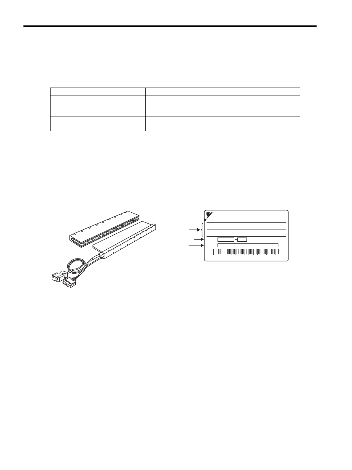
CORELESS LINEAR SERVO MOTOR
SGLGW-40A140B
94 0.8
47
WA
N
B
Ins.
O/N
S/N
YASKAWA ELECTRIC CORPORATION JAPAN
Servomotor
model
Ratings
Serial No.
Nameplate
Order No.
y Coil assembly and Magnetic way
1.1.1 Check Items
1.1 Checking Products
1.1.1 Check Items
Check the following items when the products are delivered.
Check Items Comments
Are the delivered products the ones
that were ordered?
Is there any damage? Check the overall appearance, and check for damage or scratches that
If any of the above items are faulty or incorrect, contact your Yaskawa representative or the dealer from whom
you purchased the products.
1.1.2 Linear Servomotors
The location of the nameplate varies depending on the model of the linear servomotor. The nameplate is affixed
on both the coil assembly and the magnetic way.
(1) Coreless SGLGW and SGLGM Linear Servomotors
Check the model numbers marked on the nameplates on the linear
servomotor and SERVOPACK. (Refer to the descriptions of model
numbers in the following section.)
may have occurred during shipping.
1-2
Page 25
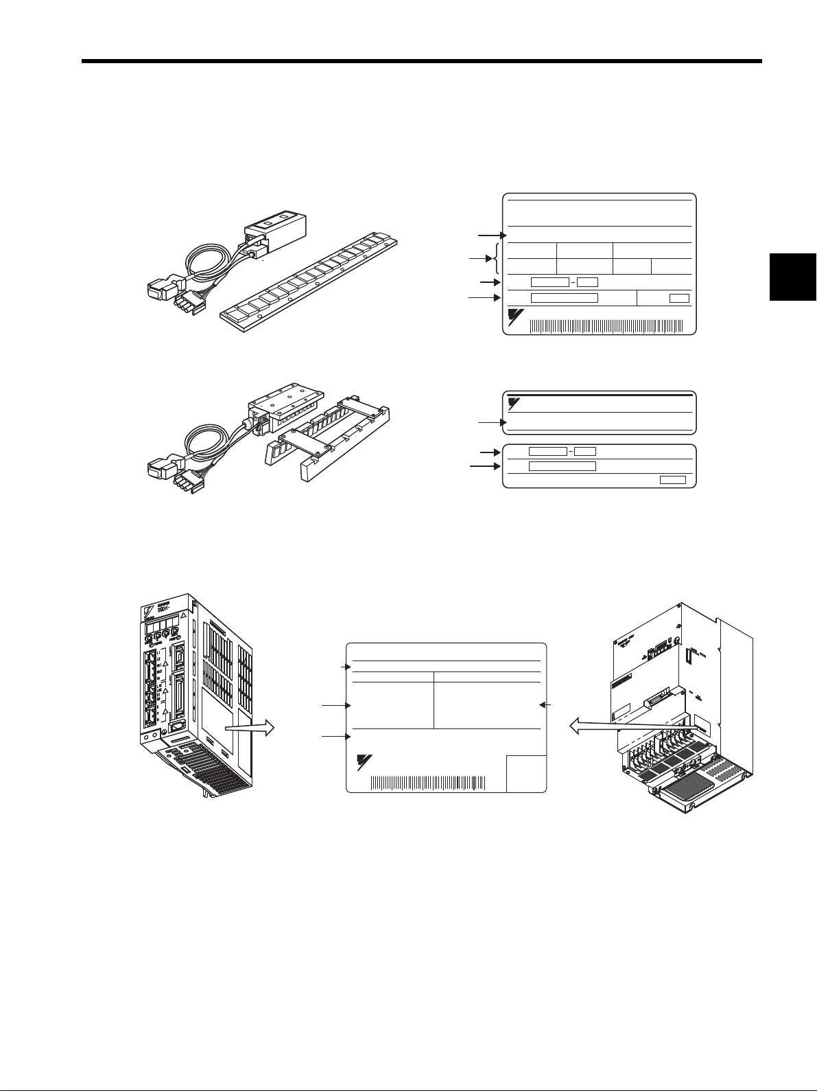
(2) SGLFW and SGLFM Linear Servomotors with F-type Iron Core and
Linear SERVO MOTOR
TYPE
200 W
1.3 A
80 N
200 V
2.5 m/s
ins.B
O/N
S/N
YASKAWA ELECTRIC MADE IN JAPAN
DATE
SGLFW-35A120A
Servomotor
model
Ratings
Serial No.
Nameplate
Nameplate
Order No.
Servomotor
model
Serial No.
Order No.
y Coil assembly
y Magnetic way
y SGLFW and SGLFM
y SGLTW and SGLTM
YASKAWA
TYPE:
O/N
S/N
MADE IN JAPAN DATE
SGLFM-20756A
Serial
number
S/N
YASKAWA ELECTRIC
MADE IN JAPAN
412808-15-1
SERVOPACK
MODEL
AC-INPUT AC-OUTPUT
VOLTS
Hz
PHASE
AMPS
200-230
50/60
3
18.6
VOLTS
PHASE
AMPS
KU (MP)
0-230
3
24.8
3.0 (4.0)
SGDH-30AE
y SGDH for 50 W to 5.0 kW y SGDH for 7.5 kW
SERVOPACK
model
Applicable
power supply
Applicable
motor
capacity
SGLTW and SGLTM Linear Servomotors with T-type Iron Core
1.1 Checking Products
1
Note: The location of the nameplate varies depending on the model and capacity of the linear servomotor.
1.1.3 SERVOPACKs
1-3
Page 26
1 Outline
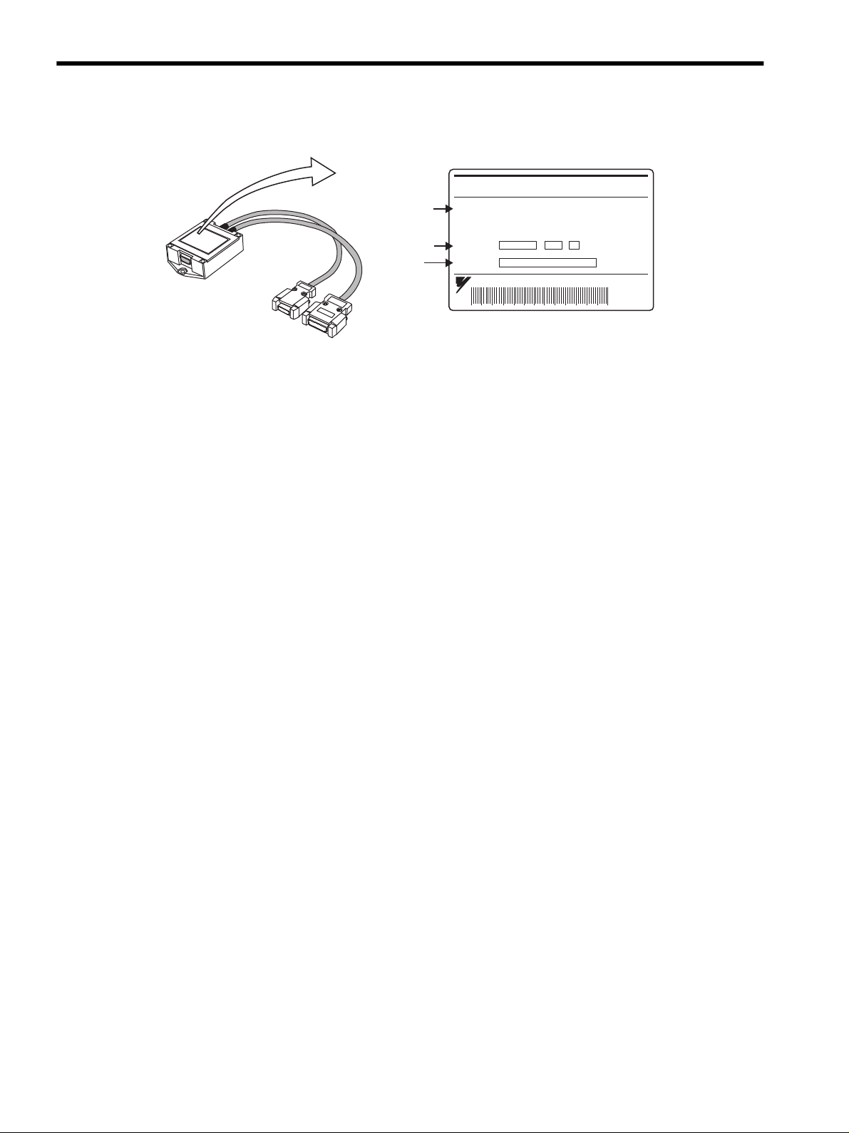
Nameplate
SERIAL CONVERTER
MODEL JZDP-D006-156
YASKAWA ELECTRIC CORPORATION
JAPAN
For : -
O/N
S/N
--
Serial No.
Order No.
Serial
converter
model
1.1.4 Serial Converter Units
1.1.4 Serial Converter Units
1-4
Page 27
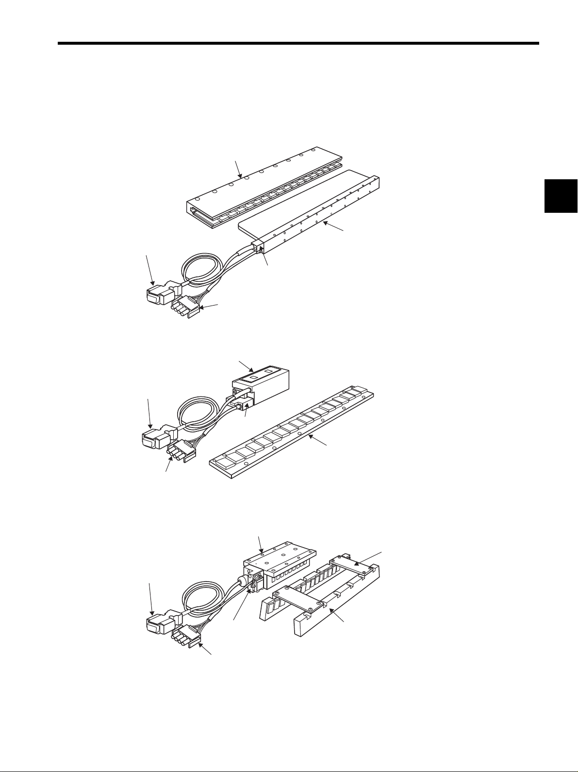
1.2 Product Part Names
Magnetic way
Coil assembly
Hall sensor unit
Main circuit cable for linear servomotor
Hall sensor cable
Magnetic way
Coil assembly
Hall sensor
unit
Main circuit cable for
linear servomotor
Hall sensor cable
Magnetic way
Coil assembly
Hall sensor unit
Main circuit cable for
linear servomotor
Spacer for
installation
Hall sensor cable
1.2.1 Linear Servomotors
Coreless SGLGW and SGLGM
(1)
1.2 Product Part Names
1
(2) SGLFW and SGLFM With F-type Iron Core
SGLTW and SGLTM With T-type Iron Core
(3)
1-5
Page 28
1 Outline
Refer to 2.3 SERVOPACK Model
Designations.
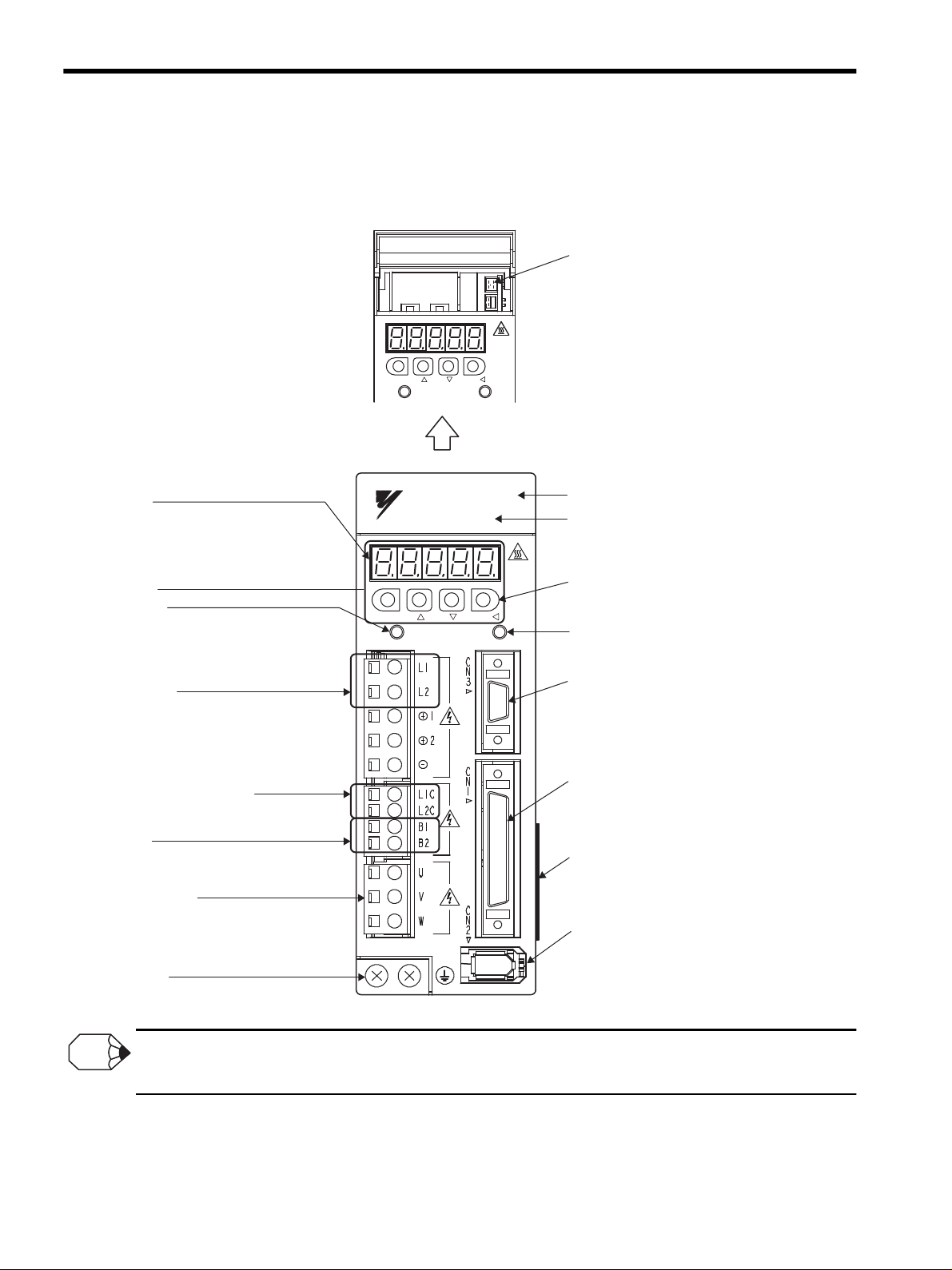
With the front cover open
SERVOPACK model
YASKAWA
YASKAWA
SERVOPACK
SGDH-
MODE/SET
CHARGE POWER
DATA/
MODE/SET DATA/
CHARGE POWER
Panel display
5-digit, 7-segment LED used to display
SERVOPACK status, alarm status, and other
values when parameters are input.
Refer to 8.1.2 Key Names and Functions.
Panel operator
Charge indicator
Lights when the main circuit power supply is
ON and stays lit as long as the main circuit power
supply capacitor remains charged. Therefore,
do not touch the SERVOPACK even after the power
supply is turned OFF if the indicator is lit.
Main circuit power
supply terminals
Used for main circuit power supply input.
Refer to 7.2 Wiring Main Circuit.
Used for control power supply input.
Refer to 7.2 Wiring Main Circuit.
Control power supply terminals
Used to connect external regenerative resistors.
Refer to 7.6 Connecting Regenerative Resistors.
Regenerative
resistor connecting terminals
Refer to 7.2 Wiring Main Circuit.
Ground terminal
Be sure to connect to protect against electrical shock.
Servomotor terminals
Connects to the servomotor power line.
Refer to 7.2 Wiring Main Circuit.
CN5 Analog monitor connector
Used to monitor motor speed, force
reference, and other values through
a special cable.
Refer to 6.8.3 Cables for Analog Monitor or
10.5 Analog Monitor.
Front cover
Power ON indicator
Lights when the control power supply is ON.
Panel keys
Used to set parameters.
Refer to 8.1.2 Key Names and Functions.
Refer to 6.8.1 Cables for Connecting Personal
Computer and 6.8.2 Digital Operator.
CN3 Connector for personal computer monitoring
and digital operator
Used to communicate with a personal computer
or to connect a digital operator.
CN1 I/O signal connector
Used for reference input signals and
sequence I/O signals.
Refer to 7.4 Examples of I/O Signal Connections.
Nameplate (side view)
Indicates the SERVOPACK model and ratings.
Refer to 1.1.3 SERVOPACKs.
CN2 Encoder connector
Connects to the serial converter unit.
Refer to 7.3 Wiring Encoders.
INFO
1.2.2 SERVOPACKs
1.2.2 SERVOPACKs
(1) SGDH for 50 W to 5.0 kW
Connecting terminal of DC Reactor
For connecting a reactor, refer to 7.5.5 DC Reactor for Harmonic Suppression.
1-6
Page 29
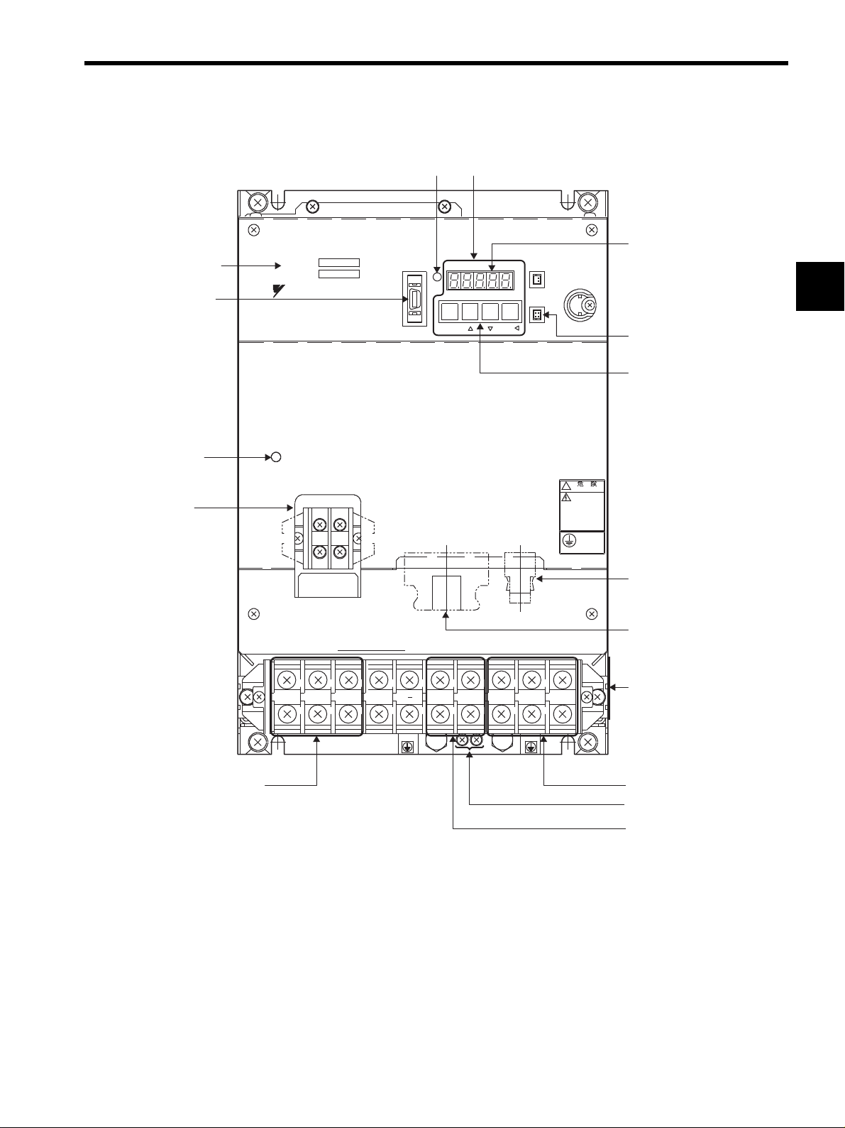
(2) SGDH for 7.5 kW
L1 L2 L3
U
B2B1
+
VW
!
WARNING
MODE/SET
Ve r.
POWER
CHARGE
SGDH-
SERVOPACK 200V
YASKAWA
Power indicator
Panel operator
Charge indicator
L1C
CN1 CN2
L2C
Main circuit power supply
terminals: L1, L2, L3
Servomotor terminals: U, V, W
Regenerative resistor
connecting terminals: B1, B2
CN3 Connector for
personal computer
monitoring and
digital operator
Nameplate (side view)
CN2 Encoder connector
CN1 I/O signal connector
Control circuit
terminal
SERVOPACK model
Ground terminal
DATA/
BATTERY
Panel display
CN5 Analog
monitor connector
Panel switch
CN8
CN5
CN3
∗
∗
1.2 Product Part Names
1
* Control circuit terminal and regenerative resistor connecting terminals differ the position of the termi-
nal block by the SERVOPACK model.
Refer to Chapter 4 SERVOPACK Specifications and Dimensional Drawings for details.
SERVOPACK model SGDH-75AE: Refer to 4.7.7 Three-phase 200 V: 7.5 kW (75AE).
SERVOPACK model SGDH-75DE: Refer to 4.7.8 Three-phase 400 V: 7.5 kW (75DE).
1-7
Page 30
1 Outline
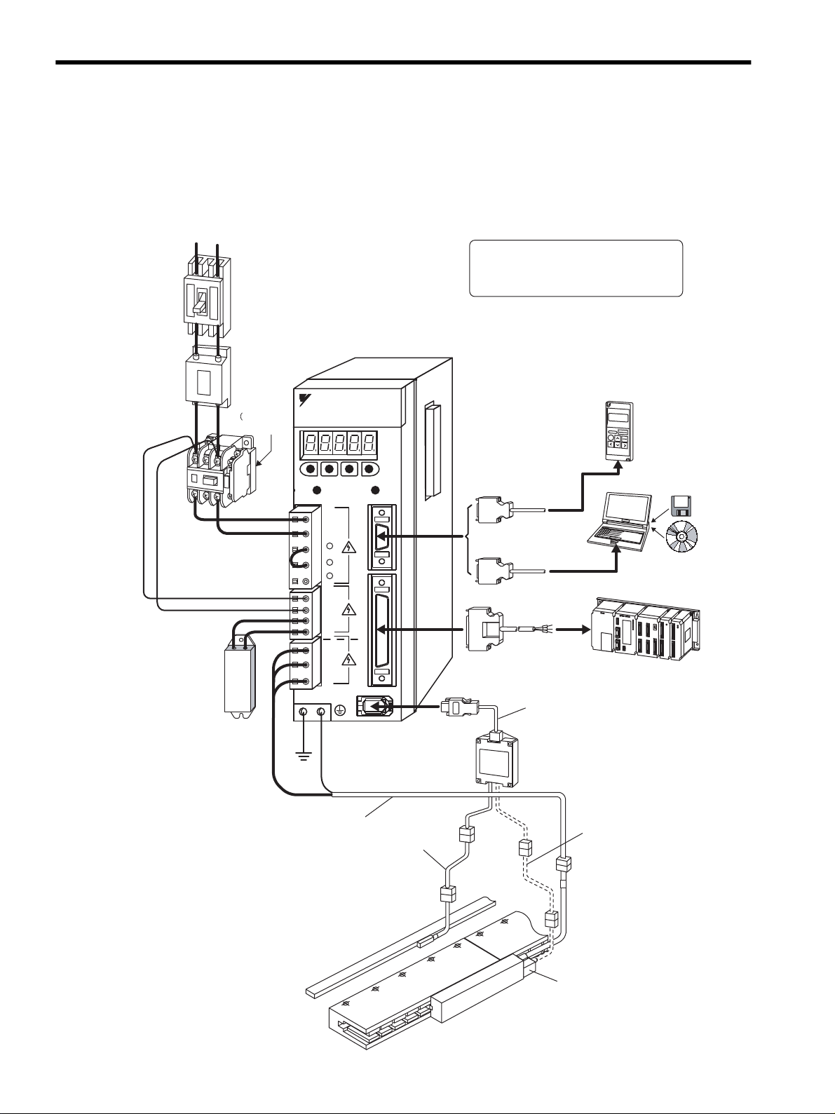
Regenerative
resistor
Noise filter
Molded-case
circuit breaker
(MCCB)
Magnetic
contactor
Digital
operator
Personal computer
Host controller
Connection cable
for digital operator
Connection cable
for personal computer
(Refer to 2.6.1.)
(Refer to 2.6.1.)
(Refer to 2.6.1.)
(Refer to 2.6.4.)
(Refer to 2.6.5.)
Refer to
2.6.3)
(Refer to 2.6.3)
(Refer to 2.6.2)
I/O signal cable
Note : To connect a DC reactor, refer to
7.5.5 DC Reactor for Harmonic
Suppression.
SGDH-AE
SERVOPACK
Power supply
Single-phase 200 VAC
Protects the power supply
line by shutting the circuit
OFF when an overcurrent
is detected.
Eliminates external
noise from the power
line.
Connect an external
regenerative resistor
to terminals B1 and B2
if the regenerative
capacity is insufficient.
Turns the servo ON
and OFF.
Install a surge
suppressor.
Linear scale
(To be provided by
users.)
Hall sensor unit
Connection cable
for hall sensor
Encoder
cable
Main circuit cable for
linear servomotor
Serial converter unit
Connection cable
for serial converter unit
(Refer to 2.5.)
(Refer to 2.5.)
(Refer to 2.5.)
(Refer to 2.5.)
(Refer to 2.4.)
R T
C
N
3
C
N
1
L1C
L2C
B1
B2
U
V
W
L1
L2
+ 1
MODE/SET
DATA/
CHARGE POWER
C
N
SGDH-
SERVOPACK
200V
YASKAWA
+ 2
-
Coreless Linear Servomotor
1.3.1 Single-phase, 200 V Main Circuit
1.3 Examples of Servo System Configurations
1.3.1 Single-phase, 200 V Main Circuit
This section describes examples of basic servo system configuration.
1-8
Page 31

Regenerative
resistor
Noise filter
Molded-case
circuit breaker
(MCCB)
Magnetic
contactor
I/O signal cable
Power supply
Three-phase 200 VAC
R S T
Protects the power
supply line by shutting
the circuit OFF when
an overcurrent is
detected.
Eliminates external noise
from the power line.
Connect an external
regenerative resistor
to terminals B1 and B2
if the regenerative
capacity is insufficient.
Turns the servo
ON and OFF.
Install a surge
suppressor.
(Refer to 2.6.1.)
(Refer to 2.6.4.)
(Refer to 2.6.5.)
(Refer to
2.6.3.)
(Refer to 2.6.3.)
(Refer to 2.6.2.)
Connection cable for
digital operator
Connection cable for
personal computer
(Refer to 2.6.1.)
Linear servomotor with core
Linear scale
(To be provided by
users)
Encoder
cable
Main circuit cable for
linear servomotor
Serial converter unit
Connection cable for
serial converter unit
(Refer to 2.5.)
(Refer to 2.5.)
(Refer to 2.5.)
(Refer to 2.5.)
(Refer to 2.4.)
Personal computer
Host controller
L1
L2
L3
U
V
W
L1C
L2C
B1
B2
B3
1
2
C
N
3
C
N
1
C
N
2
MODE/SET
DATA/
CHARGE POWER
YASKAWA
SERVOPACK
SGD
H-
200V
*1
*3
*2
*3: To connect a DC reactor, refer to 7.5.5 DC Reactor for Harmonic
Suppression.
*1: The positive terminal for the main circuit is only available for use
in the three-phase (200 VAC, 7.5 kW) SERVOPACKs.
Do not use the positive terminals 1 or 2.
*2: Before connecting an external regenerative resistor to
the SERVOPACK, be sure to disconnect the lead between terminals
B2 and B3.
Digital
operator
(Refer to 2.6.1.)
SGDH-AE
SERVOPACK
Connection cable
for hall sensor
1.3.2 Three-phase, 200 V Main Circuit
1.3 Examples of Servo System Configurations
1
1-9
Page 32

1 Outline
Digital
operator
Personal computer
(Refer to 2.6.1.)
Regenerative
resistor
Noise filter
Molded-case
circuit breaker
(MCCB)
Magnetic
contactor
Host controller
I/O signal cable
SGDH-DE
SERVOPACK
Power supply
Three-phase 400 VAC
R S T
Protects the power
supply line by shutting
the circuit OFF when
an overcurrent is
detected.
Eliminates external
noise from the power
line.
Connect an external
regenerative resistor
to terminals B1 and B2
if the rgenerative capacity
is insufficient.
Turns the servo
ON and OFF.
Install a surge
suppressor.
(Refer to 2.6.1.)
(Refer to 2.6.1.)
(Refer to 2.6.4.)
Refer to
2.6.3.)
(Refer to 2.6.3.)
(Refer to 2.6.2.)
Connection cable
for digital operator
Connection cable
for personal computer
L1
L2
L3
U
V
W
24V
0V
B1
B2
B3
1
2
C
N
3
C
N
1
C
N
2
MODE/SET
DATA/
CHARGE POWER
YASKAWA
SERVOPACK
SGD
H-
200V
+
−
DC power
supply
(24 VDC)
*1
*3
*2
(Refer to 2.6.5.)
Linear servomotor
wirh core
Linear scale
(To be provided by
users.)
Connection cable
for hall sensor
Encoder
cable
Main circuit cable for
linear servomotor
Serial convertr unit
Connection cable for
serial convertr unit
(Refer to 2.5.)
(Refer to 2.5.)
(Refer to 2.5.)
(Refer to 2.5.)
(Refer to 2.4.)
*3: To connect a DC reactor, refer to 7.5.5 DC Reactor for Harmonic
Suppression.
*1: Use a 24 VDC power supply (To be provided by users).
*2: Before connecting an external regenerative resistor to
the SERVOPACK, be sure to disconnect the lead between terminals
B2 and B3.
1.3.3 Three-phase, 400 V Main Circuit
1.3.3 Three-phase, 400 V Main Circuit
1-10
Page 33

1.4 Applicable Standards
U
L
C
R
US
LISTED
C
R
US
Σ-II Series servodrives conform to the following overseas standards.
1.4.1 North American Safety Standards (UL, CSA)
1.4 Applicable Standards
1
1.4.2
Model
SERVOPACK • SGDH
* 1. Underwriters Laboratories Inc.
* 2. Canadian Standards Association.
∗1
UL
Standards (UL File No.) CSA∗2 Standards
UL508C(E147823)
CE Marking
Model
SERVOPACK • SGDH
* TÜV Product Services GmbH
Note: For installation conditions, refer to 7.5.2 Wiring for Noise Control.
Because SERVOPACKs and linear servomotors are built-in type, reconfirmation is
required after being installed in the final product.
Low Voltage
Directive
EN50178
EMC Directive
EMI EMS
EN55011
class A group 1
CSA C22.2
No.14
EN50082-2
EN61000-6-2
or
Certifications
UL
Certifications
TÜV PS
∗
1-11
Page 34

1 Outline
1.4.2 CE Marking
1-12
Page 35

2
Selections
2.1 Linear Servomotor Model Designation - - - - - - - - - - - - - - - - - - - - - - - - - - 2-2
2.1.1 Coil Assembly - - - - - - - - - - - - - - - - - - - - - - - - - - - - - - - - - - - - - - - - - - - - - - - - - - - - 2-2
2.1.2 Magnetic Way - - - - - - - - - - - - - - - - - - - - - - - - - - - - - - - - - - - - - - - - - - - - - - - - - - - - 2-2
2.2 SERVOPACK Model Designation - - - - - - - - - - - - - - - - - - - - - - - - - - - - - - 2-3
2.3 S-II Series SERVOPACKs and Applicable Linear Servomotors - - - - - - - - - 2-4
2.4 Serial Converter Units Models - - - - - - - - - - - - - - - - - - - - - - - - - - - - - - - - 2-6
2.5 Selecting Cables - - - - - - - - - - - - - - - - - - - - - - - - - - - - - - - - - - - - - - - - - 2-7
2.6 Selecting Peripheral Devices - - - - - - - - - - - - - - - - - - - - - - - - - - - - - - - - - 2-9
2.6.1 Special Options - - - - - - - - - - - - - - - - - - - - - - - - - - - - - - - - - - - - - - - - - - - - - - - - - - - 2-9
2.6.2 Molded-case Circuit Breaker and Fuse Capacity - - - - - - - - - - - - - - - - - - - - - - - - - - 2-11
2.6.3 Noise Filters and DC Reactors - - - - - - - - - - - - - - - - - - - - - - - - - - - - - - - - - - - - - - - 2-12
2.6.4 Regenerative Resistors - - - - - - - - - - - - - - - - - - - - - - - - - - - - - - - - - - - - - - - - - - - - 2-13
2.6.5 Linear Scales - - - - - - - - - - - - - - - - - - - - - - - - - - - - - - - - - - - - - - - - - - - - - - - - - - - 2-14
2
2-1
Page 36

2 Selections
SGL 40 225 A C
Options
Code
Specifications
Applicable Model
With magnet
protection cover
Standard All motor models
Only for all Iron-core types
High thrust force
Only for the following coreless types
SGLGM-40, -60
Only for the T-type iron core types
SGLTM-20, -35, -40, -80
Note: The magnetic ways with base for
SGLTM-35H, -50H
are not available.
Linear Σ Series
Linear servomotor
Model
Code
G
F
T
Specifications
Coreless
F-type iron core
T-type iron core
M : Magnetic way
Magnet height
GM
Design revision order
A,B,C
Note: The coreless linear
servomotor has
revision CT.
Length of magnetic way
- M
With base and
magnetic cover
Y
−
C
2.1.1 Coil Assembly
2.1 Linear Servomotor Model Designation
This section describes how to check the model and ratings of the linear servomotor. The alphanumeric codes
after SGL- indicate the specifications.
2.1.1 Coil Assembly
SGL G W 㧙 40 A 140 A P
Linear Σ Series
Linear servomotor
Servomotor Model
Code
Specifications
G
Coreless
F-type iron core
F
T-type iron core
T
W : Coil assembly
Magnet height
Voltage
2.1.2 Magnetic Way
A㧦200 VAC
D㧦400 VAC
Code
Specifications
P
With hall sensor (standard)
C
Forced cooling
H
With hall sensor and forced cooling
−
Without hall sensor
Design revision order
A,B,C
Length of coil assembly
Hall Sensor/Cooling
Applicable models
All motor models
SGLGW-40A, -60A, -90A
All motor models
2-2
Page 37

2.2 SERVOPACK Model Designation
Select the SERVOPACK according to the applied linear servomotor.
10SGDH - A E
Σ-II Series SGDH
SERVOPACK
Rated Output of Applicable Servomotor (kW)
2.2 SERVOPACK Model Designation
Code
A5
01
02
04
05
08
Rated Output
0.05
0.10
0.20
0.40
0.45
0.75
Code
A
D
Code
Power Supply Voltage
Rated Output
10
15
20
30
50
75
Single/Three-phase, 200V
Three-phase, 400V
1.0
1.5
2.0
3.0
5.0
7.5
Voltage
Model (Fixed)
Code
For force, speed, and position control
E
Applicable for various application modules
Remarks
2
2-3
Page 38

2 Selections
2.3
Σ-II Series SERVOPACKs and Applicable Linear Servomotors
Linear Σ Series Linear Servomotor
SGLGW
(Coreless)
17 models
SGLFW
(With F-type iron core)
14 models
When a
Standardforce
Magnetic
Way is used.
When a
High-force
Magnetic
Way is used.
30A050C
30A080C
40A140C
40A253C
40A365C
60A140C
60A253C
60A365C
90A200C
90A370C
90A535C
40A140C
40A253C
40A365C
60A140C
60A253C
60A365C
20A090A
20A120A
35A120A
35A230A
50A200B
50A380B
1ZA200B
1ZA380B
35D120A
35D230A
50D200B
50D380B
1ZD200B
1ZD380B
Σ-II Series SGDH SERVOPACK
Single-phase
200 VAC
A5AE −−
01AE −−
01AE −−
02AE −−
04AE −−
02AE −−
04AE −−
− 08AE −
− 15AE −
− 20AE −
− 30AE −
02AE −−
04AE −−
− 05AE −
02AE −−
− 05AE −
− 10AE −
02AE −−
02AE −−
02AE −−
− 05AE −
− 08AE −
−
− 15AE −
− 30AE −
−−05DE
−−05DE
−−10DE
−−15DE
−−15DE
−−30DE
Three-phase
200 VAC
15AE −
Three-phase
400 VAC
2-4
Page 39

Linear Σ Series Linear Servomotor
SGLTW
(With T-type iron core)
22 models
Note: The model combinations shown in this table are used when the maximum rated force of the appli-
cable linear servomotor is required. To suppress rises in temperature, larger linear servomotors are
used in some cases. If so, the SERVOPACK capacity can be lowered if using a motor at a lower
force than the rated force. Calculate the required current and select a model with a margin of
approximately 20%. An allowance can be made for up to 1/3 of the combined capacity of the linear
servomotor and SERVOPACK in the table.
20A170A
20A320A
20A460A
35A170A
35A320A
35A460A
35A170H
35A320H
50A170H
50A320H
40A400B
40A600B
80A400B
80A600B
35D170H
35D320H
50D170H
50D320H
40D400B
40D600B
80D400B
80D600B
2.3 Σ-II Series SERVOPACKs and Applicable Linear Servomotors
Σ-II Series SGDH SERVOPACK
Single-phase
200 VAC
− 05AE −
− 10AE −
− 15AE −
− 08AE −
− 15AE −
− 20AE −
− 08AE −
− 15AE −
− 08AE −
− 15AE −
− 20AE −
− 50AE −
− 50AE −
− 75AE −
−−10DE
−−20DE
−−10DE
−−20DE
−−30DE
−−50DE
−−50DE
−−75DE
Three-phase
200 VAC
Three-phase
400 VAC
2
2-5
Page 40

2 Selections
2.4 Serial Converter Units Models
D008JZDP 001
Symbol
D006
D008
Serial Converter Unit Model
Appearance
Applicable
Linear Scale
Made by
Heidenhain
Made by
Renishaw
Hall Sensor
Yes
Yes
Servomotor Model
SGLGW-
(Coreless)
When a
standardforce
magnetic
way is used.
SGLGW +
SGLGM-
-M
(Coreless)
When a
high-force
magnetic
way is used.
SGLFW-
(Iron core,
F-type)
Applicable Linear Servomotor
Symbol
30A050C
30A080C
40A140C
40A253C
40A365C
60A140C
60A253C
60A365C
90A200C
90A370C
90A535C
40A140C
40A253C
40A365C
60A140C
60A253C
60A365C
20A090A
20A120A
35A120A
35A230A
50A200B
50A380B
1ZA200B
1ZA380B
35D120A
35D230A
50D200B
50D380B
1ZD200B
1ZD380B
250
251
252
253
254
258
259
260
264
265
266
255
256
257
261
262
263
017
018
019
020
181
182
183
184
211
212
189
190
191
192
Servomotor Model
SGLTW-
(Iron core,
T-type)
20A170A
20A320A
20A460A
35A170A
35A320A
35A460A
35A170H
35A320H
50A170H
50A320H
40A400B
40A600B
80A400B
80A600B
35D170H
35D320H
50D170H
50D320H
40D400B
40D600B
80D400B
80D600B
Symbol
011
012
013
014
015
016
105
106
108
109
185
186
187
188
193
194
195
196
197
198
199
200
2-6
Note: When using a 400-V winding linear servomotor with a 200-V SERVOPACK, the parameters in the
serial converter should be changed. Contact your Yaskawa representatives.
Page 41

2.5 Selecting Cables
SERVOPACK
Linear scale
(To be provided
by users.)
Linear servomotor
Hall sensor
unit
Serial converter
unit
YASKAWA
SERVOPACK
SGDH-
200V
L1
L2
L3
U
V
W
L1C
L2
B1
B2
B3
3
1
2
C
N
3
C
N
1
C
N
2
2
MODE/SET DATA/
CHARGE
POWER
CN2
SERVOPACK
end
Linear servomotor
end
SERVOPACK
end
Linear servomotor
end
SERVOPACK
end
Linear servomotor
end
Linear scale
end
Serial converter unit
end
2.5 Selecting Cables
2
Name Connection
c
Linear Servomotor Main
Circuit Cables
Between SERVOPACK and linear
servomotor
d
Encoder
Cables
Between serial converter unit and linear scale
Applicable
Linear Servo-
motor Model
SGLGW-30,-40
and -60
SGLFW-20
SGLFW-35
SGLGW-90
SGLFW-50 and
-1Z
SGLTW-20,-35
and -50
SGLTW-40 and
-80
All models
Cable
Length
1 m
3 m
5 m
10 m
15 m
20 m
1 m
3 m
5 m
10 m
15 m
20 m
1 m
3 m
5 m
10 m
15 m
20 m
1 m
3 m
5 m
10 m
15 m
Cable Type Specifications
JZSP-CLN11-01
JZSP-CLN11-03
JZSP-CLN11-05
JZSP-CLN11-10
JZSP-CLN11-15
JZSP-CLN11-20
JZSP-CLN21-01
JZSP-CLN21-03
JZSP-CLN21-05
JZSP-CLN21-10
JZSP-CLN21-15
JZSP-CLN21-20
JZSP-CLN39-01
JZSP-CLN39-03
JZSP-CLN39-05
JZSP-CLN39-10
JZSP-CLN39-15
JZSP-CLN39-20
JZSP-CLL00-01
JZSP-CLL00-03
JZSP-CLL00-05
JZSP-CLL00-10
JZSP-CLL00-15
Refer-
ence
6.1
6.3
2-7
Page 42

2 Selections
SERVOPACK
end
Serial converter unit
end
Serial converter unit
end
Hall sensor unit
end
Name Connection
e
Connection
cables for serial converter
unit
f
Connection
cables for hall
sensor
Between SERVOPACK connector CN2
and
serial converter unit
Between serial converter unit and hall sensor
unit
A connector is not provided on the linear servomotor end of the main circuit cable, type JZSP-
Note:
CLN39-. The user must provide the connector on the linear servomotor end. For details on the
required connector, refer to
Applicable
Linear Servo-
motor Model
All models
All models
Cable
Length
1 m
3 m
5 m
10 m
15 m
20 m
1 m
3 m
5 m
10 m
15 m
Cable Type Specifications
JZSP-CLP70-01
JZSP-CLP70-03
JZSP-CLP70-05
JZSP-CLP70-10
JZSP-CLP70-15
JZSP-CLP70-20
JZSP-CLL10-01
JZSP-CLL10-03
JZSP-CLL10-05
JZSP-CLL10-10
JZSP-CLL10-15
6.1 Linear Servomotor Main Circuit Cables
Refer-
ence
6.2
6.4
.
2-8
Page 43

2.6 Selecting Peripheral Devices
Personal
computer
d
Digital operator
Host controller
I/O signal cable
c
Connection cable
for digital operator
Connection cable
for personal computer
YASKAWA
SERVOPACK
SGDH-
200V
L1
L2
L3
U
V
W
L1C
L2
B1
B2
B3
1
2
C
N
3
C
N
1
C
N
2
MODE/SET DATA/
CHARGE
POWER
CN3
CN1
e
f
CN5
CN8
g
Analog monitor cable
YASKAWA
SERVOPACK
SGDH-
200V
L1
L2
L3
U
V
W
L1C
L2
B1
B2
B3
1
2
C
N
3
C
N
1
C
N
2
MODE/SET DATA/
CHARGE
POWER
NS100
S
W
1
S
W
2
A
R
C
N
6
A
C
N
6
B
C
N
4
5
4
0
9
6
1
2
7
8
3
3
5
4
0
9
6
1
2
7
8
NS300
5
4
0
9
6
1
2
7
8
3
X
10
X
1
D
R
C
N
11
M
S
N
S
MECHATROLINK-I
I/F Unit
(NS100)
DeviceNet
I/F Unit
(NS300)
NS600
INDEXER
Module
(NS600)
PROFIBUS-DP
I/F Unit
(NS500)
Connector
CN6A
CN11
CN7
CN4
CN6
CN6
CN4
CN11
CN6
CN4
CN6B
CN4
NS115
S
W
1
S
W
2
A
R
C
N
6
A
C
N
6
B
C
N
4
MECHATROLINK-II
I/F Unit
(NS115)
CN6A
CN6B
CN4
h
6
NS500
CN10
2.6.1 Special Options
2.6 Selecting Peripheral Devices
2
2-9
Page 44

2 Selections
CN1
CN3
Operator
end
SERVOPACK
end
CN3
Personal
computer end
SERVOPACK
end
CN5
SERVOPACK end
Monitor end
2.6.1 Special Options
Name Length Type Specifications
Connector terminal block
c
converter unit
I/O Signal
Cables
Cable with
loose wires at
one end
Cable with Female D-sub Output
Connector**
d Digital Operator
e
Connection Cable
for Digital Operator
Terminal block and 0.5 m connection
cable
JUSP-TA50P
1 m JZSP-CKI01-1 Loose wires at host controller end
2 m JZSP-CKI01-2
3 m JZSP-CKI01-3
0.5m JZSP–CKI0D–D50
Cable
1m JZSP–CKI0D–01
2m JZSP–CKI0D–02
3m JZSP–CKI0D–03
With connection cable (1 m)
JUSP-OP02A-2
Only required when using Σ series
Digital Operator JUSP-OP02A-1.
1 m JZSP-CMS00-1
Refer-
ence
6.8.4
6.7.1
–
6.8.2
f
D-Sub 9-pin (For DOS/V)
Connection Cable for Personal
Computer
g
Analog Monitor Cable
Application Module
h
* For details, refer to the manuals of each application module.
**The 50-pin female D-sub output connector mates to a customer-supplied 3rd party terminal block. (e.g.,
Wago #289-449, Weidmuller #919658, Phoenix #2283647, Amphenol/Sine #20-51039, and many others)
∗
2 m YS-12
1 m
JZSP-CA01
(or DE9404559)
Name Type
MECHATROLINK-I Application Module
(NS100)
MECHATROLINK-II Application Module
(NS115)
JUSP-NS100
JUSP-NS115
DeviceNet Application Module (NS300) JUSP-NS300
PROFIBUS-DP Application Module (NS500) JUSP-NS500
INDEXER Application Module (NS600) JUSP-NS600
6.8.1
6.8.3
Refer-
ence
6.8.10
6.8.10
6.8.11
6.8.12
6.8.13
2-10
Page 45

2.6.2 Molded-case Circuit Breaker and Fuse Capacity
IMPORTANT
Current Capacity of the
Main
Circuit
Power
Supply
Singlephase
200 V
Threephase
200 V
Threephase
400 V
SERVOPACK
Model
Power Supply
Capacity per
SERVOPACK
Capacity
(kW)
SGDH-
(kVA)
0.05 A5AE 0.25
0.10 01AE 0.40
0.20 02AE 0.75
0.40 04AE 1.2 8
0.45 05AE 1.4 4
0.75 08AE 1.9
1.0 10AE 2.3
1.5 15AE 3.2 10
2.0 20AE 4.3 13
3.0 30AE 5.9 17
5.0 50AE 7.5 28 67A
7.5 75AE 15.5 41
0.45 05DE 1.1 1.6
1.0 10DE 2.3 3.4
1.5 15DE 3.2 4.6
2.0 20DE 4.9 7.1
3.0 30DE 6.7 9.7
5.0 50DE 10.3 14.9 78A
7.5 75DE 15.4 22.3
* 1. Nominal value at the rated load. The specified derating is required to select an appropriate
fuse capacity.
* 2. Cutoff characteristics (25°C): 300% five seconds min. and inrush current of 20ms.
* 3. A preventive circuit for inrush current is not built in the 24 VDC control power supply. The
protective circuit must be designed by the customer.
* 4. Make sure the current capacity is accurate. For the SERVOPACK with the cooling fan built-
in, an inrush current flows; 200 % of the current capacity in the table above for two seconds,
when turning ON the control circuit power supply to start the fan working.
Note: Do not use a fast-acting fuse. Because the SERVOPACK’s power supply is a capacitor
input type, a fast-acting fuse may blow when the power is turned ON.
Molded-case Circuit Breaker
and the Fuse (A
(Refer to 6.8.7)
Main Circuit
Power Supply
4
7
2.6 Selecting Peripheral Devices
∗1,∗2
)
rms
Control Cir-
cuit Power
Supply
Power Supply
Inrush Current
Main Circuit
0.13 63A 60A
118A
4
∗
0.15
63A
4
0.27
∗
40A
10A
4
∗
0.7
20A
4
1.2
∗
20A
Control Cir-
cuit Power
Supply
60A
(24 VDC)
∗
2
3
The SGDH SERVOPACK does not include a protective grounding circuit. Install a ground-fault protector
to protect the system against overload and short-circuit or protective grounding combined with the moldedcase circuit breaker.
2-11
Page 46

2 Selections
2.6.3 Noise Filters and DC Reactors
2.6.3 Noise Filters and DC Reactors
Main Circuit
Power
Supply
Single-phase
200 V
Three-phase
200 V
Three-phase
400 V
Note: 1. If some SERVOPACKs are wired at the same time, select the proper magnetic contactors accord-
SERVOPACK Model
Capacity
(kW)
0.05 A5AE
0.10 01AE X5071
0.20 02AE X5070
0.40 04AE FN2070-10/07
0.45 05AE FN258L-7/07
0.75 08AE
1.0 10AE
1.5 15AE
2.0 20AE
3.0 30AE FN258L-30/07
5.0 50AE FMAC-0934-5010
7.5 75AE FMAC-0953-6410
0.45 05DE
1.0 10DE
1.5 15DE
2.0 20DE
3.0 30DE
5.0 50DE
7.5 75DE
ing to the total capacity.
2. The following table shows the manufacturers of each device.
SGDH
-
Recommended Noise Filter
(Refer to 6.8.8.)
Type Specifications
FN2070-6/07
FN258L-16/07
FN258L-7/07
FN258L-16/07
FS5559-35-33
Single-phase
250 VAC, 6 A
Single-phase
250 VAC, 10 A
Three-phase
480 VAC, 7 A
Three-phase
480 VAC, 16 A
Three-phase
480 VAC, 30 A
Three-phase
440 VAC, 50 A
Three-phase
440 VAC, 64 A
Three-phase
480 VAC, 7 A
Three-phase
480 VAC, 16 A
Three-phase
480 VAC, 35 A
(Refer to
DC
Reactor
6.8.9.)
−
X5069
X5061
X5060
X5059
X5068
−
X5074
X5075
X5076
X5077
−
2-12
Peripheral Device Manufacturer
Noise Filter
DC Reactor Yaskawa Controls Co., Ltd.
FN, FS type: Schaffner Electronic
FMAC type: SCHURTER (formely TIMONTA)
Page 47

2.6.4 Regenerative Resistors
2.6 Selecting Peripheral Devices
SERVOPACK Model
Main Circuit
Power Supply
Single-phase
200 V
Three-phase
200 V
Three-phase
400 V
* 1. For the optional JUSP-RA05 Regenerative Resistor Unit.
* 2. For the optional JUSP-RA18 Regenerative Resistor Unit.
Capacity
(kW)
0.05 A5AE
0.10 01AE
0.20 02AE
0.40 04AE
0.45 05AE
0.75 08AE
1.0 10AE
1.5 15AE 30 70
2.0 20AE 25 140
3.0 30AE 12.5 140
5.0 50AE 8 280
7.5 75AE
0.45 05DE
1.0 10DE
1.5 15DE
2.0 20DE
3.0 30DE
5.0 50DE 32 180
SGDH-
Resistance
Regenerative Resistor
(Refer to 6.8.5, 6.8.6, and 7.6.)
Built-in
(Ω)
−−−
50 60
1
∗
(3.13)
108 70
45 140
2
∗
(18)
Capacity
(W)
1
∗
(1760)
2
∗
(880)
Externally
connected
2
−
JUSP-RA05
−
JUSP-RA187.5 75DE
Note: 1. If the SERVOPACK cannot process the regenerative power, an external regenerative resistor is
required. Refer to 6.8.5 External Regenerative Resistor, 6.8.6 Regenerative Resistor, and 7.6
Connecting Regenerative Resistors.
2. The following table shows the manufacturers of each device.
Peripheral Device Manufacturer
External Regenerative Resistor Iwaki Wireless Research Institute
External Regenerative Unit Yaskawa Electric Corporation
2-13
Page 48

2 Selections
64000
must result in an integer number
Pn280(Scale pitch (μm))
Examples
Correct: 1,2,4,8,10,16,20,40
Incorrect: 3,12,18
2.6.5 Linear Scales
2.6.5 Linear Scales
Max. Value
of Encoder
Output
Resolution
Manufacturer Type Output Signal
Resolution
(μm/pulse)
Scale Pitch
(μm)
(Pn281)
31 5
Renishaw Inc. RGH22B
0.078 20
63 4
127 2
255 1
63 5
LIDA187
0.156 40
127 4
255 2
Heidenhain
Corp.
LIDA487
LIDA489
1Vpp
Analog voltage
0.078 20
31 5
63 4
127 2
255 1
31 1.0
LIF181
0.016 4
63 0.8
127 0.4
255 0.2
Note: 1. The linear scale signal is multiplied by eight bits (256 segmentation) inside the serial converter
unit.
2. Using the zero-point signal with a linear scale made by Renishaw Inc. may cause a deviation in
the home position. If so, adjust the setting so that the zero-point is output only in one direction
by using BID/DIR signal.
3. This list does not cover all the applicable types of linear scales. And, the linear scales listed in
the table may not be applicable or available if their specifications have been modified or their
production has been stopped.
Check the most recent catalog of the linear scale manufacturer to select a linear scale that meets
the specifications described in 5.1 Serial Converter Unit Specifications.
4. Select a linear scale so that the current consumption of the linear scale is 190 mA max.
5. At parameter (Pn280), set the scale pitch of the linear scale so that it satisfies the following condition. Otherwise, satisfactory control cannot be obtained.
Max. Speed of
Applicable Linear
Servomotor
(m/s)
2-14
Page 49

3
Specifications and Dimensional Drawings
3.1 Ratings and Specifications of SGLGW/SGLGM - - - - - - - - - - - - - - - - - - - - 3-2
3.2 Ratings and Specifications of SGLFW/SGLFM - - - - - - - - - - - - - - - - - - - -3-6
3.3 Ratings and Specifications of SGLTW/SGLTM - - - - - - - - - - - - - - - - - - - - - 3-9
3.4 Mechanical Specifications of Linear Servomotors - - - - - - - - - - - - - - - - - 3-15
3.5 Quick Guide to Linear Servomotor Dimensional Drawings - - - - - - - - - - - 3-16
3.6 Dimensional Drawings of SGLGW/SGLGM Linear Servomotors - - - - - - - 3-17
3.6.1 SGLG-30 Linear Servomotors - - - - - - - - - - - - - - - - - - - - - - - - - - - - - - - - - - - - - - 3-17
3.6.2 SGLG-40 Linear Servomotors - - - - - - - - - - - - - - - - - - - - - - - - - - - - - - - - - - - - - - 3-19
3.6.3 SGLG-60 Linear Servomotors - - - - - - - - - - - - - - - - - - - - - - - - - - - - - - - - - - - - - - 3-22
3.6.4 SGLG-90 Linear Servomotors - - - - - - - - - - - - - - - - - - - - - - - - - - - - - - - - - - - - - - 3-25
3
3.7 Dimensional Drawings of SGLFW/SGLFM Linear Servomotors - - - - - - - - 3-27
3.7.1 SGLF-20 Linear Servomotors - - - - - - - - - - - - - - - - - - - - - - - - - - - - - - - - - - - - - - 3-27
3.7.2 SGLF-35 Linear Servomotors - - - - - - - - - - - - - - - - - - - - - - - - - - - - - - - - - - - - - - 3-29
3.7.3 SGLF-50 Linear Servomotors - - - - - - - - - - - - - - - - - - - - - - - - - - - - - - - - - - - - - - 3-31
3.7.4 SGLF-1Z Linear Servomotors - - - - - - - - - - - - - - - - - - - - - - - - - - - - - - - - - - - - - - 3-33
3.8 Dimensional Drawings of SGLTW / SGLTM Linear Servomotors - - - - - - - 3-35
3.8.1 SGLT-20 Linear Servomotors - - - - - - - - - - - - - - - - - - - - - - - - - - - - - - - - - - - - - - 3-35
3.8.2 SGLT-35A Linear Servomotors - - - - - - - - - - - - - - - - - - - - - - - - - - - - - - 3-38
3.8.3 SGLT-35H Linear Servomotors - - - - - - - - - - - - - - - - - - - - - - - - - - - - - - 3-41
3.8.4 SGLT-40 Linear Servomotors - - - - - - - - - - - - - - - - - - - - - - - - - - - - - - - - - - - - - - 3-43
SGLT-50
3.8.5
3.8.6 SGLT-80 Linear Servomotors - - - - - - - - - - - - - - - - - - - - - - - - - - - - - - - - - - - - - - 3-48
Linear Servomotors - - - - - - - - - - - - - - - - - - - - - - - - - - - - - - - - - - - - - - 3-46
3-1
Page 50

3 Specifications and Dimensional Drawings
N /
w
3.1 Ratings and Specifications of SGLGW/SGLGM
(1) Ratings and Specifications
• Time Rating: Continuous
• Insulation Resistance: 500 VDC, 10 MΩ min.
• Ambient Temperature: 0 to 40 °C (32 to 104°F)
• Excitation: Permanent magnet
• Dielectric Strength: 1500 VAC for 1 minute
• Protection Methods: Self-cooled, air-cooling
• Ambient Humidity: 20 to 80 % (no condensation)
• Allowable Winding Temperature: 130 °C (266°F)
(Insulation class B)
(a) With Standard-force Magnetic Ways
The following table shows the ratings and specifications when the standard-force magnetic ways are used.
Linear Servomotor
Model SGLGW-
Rated Speed m / s
Peak Speed m / s
Rated Force
Rated Current
Instantaneous Peak
Force
Instantaneous Peak
Current
Coil Assembly Mass kg
Force Constant N / A
BEMF Constant V /(m / s)
Motor Constant
Electrical Time
Constant
Mechanical Time
Constant
Thermal Resistance
With Heat Sink
Thermal Resistance
Without Heat Sink
Magnetic Attraction N
Note: 1. The items marked with an * and “Force and Speed Characteristics” are the values at a motor winding tem-
∗
∗
∗
∗
perature of 100 °C (212°F) during operation in combination with a SERVOPACK. The others are at 20 °C
(68°F).
N
Arms
N
Arms
rms
ms
ms
K / W
K / W
30A 40A 60A 90A
050C 080C 140C 253C 365C 140C 253C 365C 200C 370C 535C
1.5 1.5 1.5 1.5 1.5 1.5 1.5 1.5 1.5 1.5 1.5
55555555555
12.5 25 47 93 140 70 140 210 325 550 750
0.51 0.79 0.8 1.6 2.4 1.2 2.2 3.3 4.4 7.5 10.2
40 80 140 280 420 220 440 660 1300 2200 3000
1.62 2.53 2.4 4.9 7.3 3.5 7.0 10.5 17.6 30.0 40.8
0.10 0.15 0.34 0.60 0.87 0.42 0.76 1.10 2.15 3.6 4.9
26.4 33.9 61.5 61.5 61.5 66.6 66.6 66.6 78 78 78
8.8 11.3 20.5 20.5 20.5 22.2 22.2 22.2 26.0 26.0 26.0
3.7 5.6 7.8 11.0 13.5 11.1 15.7 19.2 26.0 36.8 45.0
0.2 0.4 0.4 0.4 0.4 0.5 0.5 0.5 1.4 1.4 1.4
7.30 4.78 5.59 4.96 4.77 3.41 3.08 2.98 3.18 2.66 2.42
5.19 3.11 1.67 0.87 0.58 1.56 0.77 0.51 0.39 0.26 0.22
−−3.02 1.80 1.23 2.59 1.48 1.15 −−−
00000000000
3-2
Page 51

3.1 Ratings and Specifications of SGLGW/SGLGM
N /
w
2. The above specifications show the values under the cooling condition when a heat sink (aluminium board)
listed in the following table is mounted on the coil assembly.
Linear Servomotor
Model SGLGW-
30A050C
30A080C
40A140C
60A140C
40A253C
60A253C
40A365C
60A365C
90A200C
90A370C
90A535C
The values of peak speed in the table indicate the maximum speed that can be controlled from SERVOPACK. Refer to
Force and Speed Characteristics for the actual motor peak speed.
Heat Sink Size
in mm (in)
200 × 300 × 12
(7.87 × 11.81 × 0.47)
300 × 400 × 12
(11.81 × 15.75 × 0.47)
400 × 500 × 12
(15.75 × 19.69 × 0.47)
800 × 900 × 12
(31.50 × 35.43 × 0.47)
(b) With High-force Magnetic Ways
The following table shows the ratings and specifications when the high-force magnetic ways are used.
Linear Servomotor
Model SGLGM-C-M
+
SGLGW-
Rated Speed m / s
Peak Speed m / s
Rated Force
Rated Current
Instantaneous Peak
Force
Instantaneous Peak
Current
Coil Assembly Mass kg
Force Constant N / A
BEMF Constant V /(m / s)
Motor Constant
Electrical Time
Constant
Mechanical Time
Constant
Thermal Resistance
With Heat Sink
Thermal Resistance
Without Heat Sink
Magnetic Attraction N
∗
∗
∗
∗
N
Arms
N
Arms
rms
ms
ms
K / W
K / W
140C 253C 365C 140C 253C 365C
40A 60A
1.5 1.5 1.5 1.5 1.5 1.5
555555
57 114 171 85 170 255
0.8 1.6 2.4 1.2 2.2 3.3
230 460 690 360 720 1080
3.2 6.5 9.7 5.0 10.0 14.9
0.34 0.60 0.87 0.42 0.76 1.10
76.0 76.0 76.0 77.4 77.4 77.4
25.3 25.3 25.3 25.8 25.8 25.8
9.6 13.6 16.7 12.9 18.2 22.3
0.4 0.4 0.4 0.5 0.5 0.5
3.69 3.24 3.12 2.52 2.29 2.21
1.67 0.87 0.58 1.56 0.77 0.51
3.02 1.80 1.23 2.59 1.48 1.15
000000
3
3-3
Page 52

3 Specifications and Dimensional Drawings
SGLGW-30A050C
6.0
5.0
4.0
3.0
2.0
1.0
0
0 1020304050
Motor
speed
m/s
Force (N)
SGLGW-30A080C
6.0
5.0
4.0
3.0
2.0
1.0
0
0 20406080100
Motor
speed
m/s
Force (N)
A
B
A
B
SGLGW-40A140C
Motor
speed
m/s
Force (N)
SGLGW-40A253C
6.0
5.0
4.0
3.0
2.0
1.0
0
0 100 200 300 400
Motor
speed
m/s
Force (N)
A
B
SGLGW-40A365C
6.0
5.0
4.0
3.0
2.0
1.0
0
0 150 300 450 600
Motor
speed
m/s
Force (N)
A
B
SGLGW-60A140C
6.0
5.0
4.0
3.0
2.0
1.0
0
0 100 200 300
Motor
speed
m/s
Force (N)
A
B
SGLGW-60A253C
6.0
5.0
4.0
3.0
2.0
1.0
0
0 200 400 600
Motor
speed
m/s
Force (N)
A
B
A
B
SGLGW-60A365C
6.0
5.0
4.0
3.0
2.0
1.0
0
0 300 600 900
Motor
speed
m/s
Force (N)
SGLGW-90A200C
Motor
speed
m/s
Force (N)
SGLGW-90A370C
6.0
5.0
4.0
3.0
2.0
1.0
0
0 500 1000 1500 2000 2500
Motor
speed
m/s
Force (N)
A
B
A
B
SGLGW-90A535C
6.0
5.0
4.0
3.0
2.0
1.0
0
0 700 1400 2100 2800 3500
Motor
speed
m/s
Force (N)
A Continuous duty zone
B
Intermittent duty zone
6.0
5.0
4.0
3.0
2.0
1.0
0
0 30 60 90 120 150
A
B
6.0
5.0
4.0
3.0
2.0
1.0
0
0 300 600 900 1200 1500
A
B
(2) Force and Speed Characteristics
(a) With Standard-force Magnetic Ways
3-4
Page 53

(b) With High-force Magnetic Ways
SGLGW-40A140C
Motor
speed
m/s
Force N
SGLGW-40A253C
Motor
speed
m/s
Force N
SGLGW-40A365C
Motor
speed
m/s
Force N
SGLGW-60A140C
Motor
speed
m/s
Force (N)
SGLGW-60A253C
Motor
speed
m/s
Force (N)
SGLGW-60A365C
Motor
speed
m/s
Force (N)
A Continuous duty zone
B
Intermittent duty zone
5
4
3
2
1
0
0 50 150100 200 250
A
B
5
4
3
2
1
0
0 100 300200 400 500
A
B
5
4
3
2
1
0
0 150 450300 600 750
A
B
5
4
3
2
1
0
0 80 240160 320 400
A
B
5
4
3
2
1
0
0 160 480320 640 800
A
B
5
4
3
2
1
0
0 240 720480 960 1200
A
B
3.1 Ratings and Specifications of SGLGW/SGLGM
3
3-5
Page 54

3 Specifications and Dimensional Drawings
N /
w
3.2 Ratings and Specifications of SGLFW/SGLFM
(1) Ratings and Specifications
• Time Rating: Continuous
• Insulation Resistance: 500 VDC, 10 MΩ min.
• Ambient Temperature: 0 to 40 °C (32 to 104°F)
• Excitation: Permanent magnet
• Dielectric Strength: 1500 VAC for 1 minute
• Protection Methods: Self-cooled
• Ambient Humidity: 20 to 80 % (no condensation)
• Allowable Winding Temperature: 130 °C (266°F)
(Insulation class B)
Ratings and Specifications of SGLFW Linear Servomotors with F-type Iron Core
Voltage 200V 400V
Linear Servomotor
Model SGLFWRated Speed m / s
Peak Speed m / s
Rated Force
Rated Current
∗
∗
Instantaneous Peak
∗
Force
Instantaneous Peak
∗
Current
N
Arms
N
Arms
Coil Assembly Mass kg
Force Constant N / Arms
BEMF Constant V /(m / s)
Motor Constant
Electrical Time
Constant
Mechanical Time
Constant
Thermal Resistance
With Heat Sink
Thermal Resistance
Without Heat Sink
ms
ms
K / W
K / W
Magnetic Attraction N
20A 35A 50A 1ZA 35D 50D 1ZD
090A 120A 120A 230A 200B 380B 200B 380B 120A 230A 200B 380B 200B 380B
5 3.5 2.5 3 1.5 1.5 1.5 1.5 1.5 1.5 1.5 1.5 1.5 1.5
55555555555555
25 40 80 160 280 560 560 1120 80 160 280 560 560 1120
0.7 0.8 1.4 2.8 5.0 10.0 8.7 17.5 0.7 1.4 2.3 4.5 4.9 9.8
86 125 220 440 600 1200 1200 2400 220 440 600 1200 1200 2400
3.0 2.9 4.4 8.8 12.4 25.0 21.6 43.6 2.3 4.6 5.6 11.0 12.3 24.6
0.7 0.9 1.3 2.3 3.5 6.9 6.4 11.5 1.3 2.3 3.5 6.9 6.4 11.5
36.0 54.0 62.4 62.4 60.2 60.2 69.0 69.0 120.2 120.2 134.7 134.7 122.6 122.6
12.0 18.0 20.8 20.8 20.1 20.1 23.0 23.0 40.1 40.1 44.9 44.9 40.9 40.9
7.9 9.8 14.4 20.4 34.3 48.5 52.4 74.0 13.8 19.5 33.4 47.2 51.0 72.1
3.2 3.3 3.6 3.6 15.9 15.8 18.3 18.3 3.5 3.5 15.0 15.0 17.4 17.2
11.0 9.3 6.2 5.5 3.0 2.9 2.3 2.1 5.5 5.5 3.2 3.2 2.5 2.2
4.35 3.19 1.57 0.96 0.56 0.38 0.47 0.2 1.57 0.96 0.56 0.38 0.47 0.2
7.69 5.02 4.10 1.94 1.65 0.95 1.3 0.73 4.1 1.94 1.65 0.95 1.3 0.73
314 462 809 1586 1650 3260 3300 6520 810 1590 1650 3260 3300 6520
Note: 1. The items marked with an * and “Force and Speed Characteristics” are the values at a motor winding tem-
perature of 100 °C (212°F) during operation in combination with a SERVOPACK. The others are at 20 °C
(68°F).
2. The above specifications show the values under the cooling condition when a heat sink (aluminium board)
listed in the following table is mounted on the coil assembly.
Linear Servomotor
Model SGLFW-
20A090A
20A120A
35120A
35230A
50200B
50380B
1Z200B
1Z380B
Heat Sink Size
in mm (in)
125 × 125 × 13
(4.92 × 4.92 × 0.51)
254 × 254 × 25
(10.0 × 10.0 × 0.98)
400 × 500 × 40
(15.75 × 19.69 × 1.57)
609 × 762 × 50
(23.98 × 30.00 × 1.97)
3. The values of peak speed in the table indicate the maximum speed that can be controlled from
SERVOPACK. Refer to Force and Speed Characteristics for the actual motor peak speed.
3-6
Page 55

(2) Force and Speed Characteristics
6
5
4
3
2
1
0
0 20 40 60 80 100
Motor
speed
m/s
Force (N)
A
B
6
5
4
3
2
1
0
0 40 80 120 140
Motor
speed
m/s
Force (N)
A
B
SGLFW-20A090A SGLFW-20A120A
SGLFW-35A120A SGLFW-35A230A
6
5
4
3
2
1
0
0 50 100 150 200 250
Motor
speed
m/s
Force (N)
A
B
6
5
4
3
2
1
0
0 100 200 300 400 500
Motor
speed
m/s
Force (N)
A
B
A: Continuous duty zone
B: Intermittent duty zone
6
5
4
3
2
1
0
0 200 400 600 800
Motor
speed
m/s
Force (N)
A
B
6
5
4
3
2
1
0
0 500 1000 1500
Motor
speed
m/s
Force (N)
A
B
6
5
4
3
2
1
0
0 15001000500
Motor
speed
m/s
Force (N)
A
B
6
5
4
3
2
1
0
0 1000 2000 3000
Motor
speed
m/s
Force (N)
A
B
SGLFW-50A200B
SGLFW-50A380B
SGLFW-1ZA200B
SGLFW-1ZA380B
(a) 200-V Class
3.2 Ratings and Specifications of SGLFW/SGLFM
3
3-7
Page 56

3 Specifications and Dimensional Drawings
Motor
speed
m/s
Force (N)
Motor
speed
m/s
Force (N)
A: Continuous duty zone
B: Intermittent duty zone
SGLFW-35D120A
5
6
4
3
2
1
0
5
6
4
3
2
1
0
0 15050 100 200 250
BA
SGLFW-35D230A
0 100 200 300 400 500
BA
6
5
4
3
2
1
0
0 200 400 600 800
Motor
speed
m/s
Force (N)
A
B
6
5
4
3
2
1
0
0 500 1000 1500
Motor
speed
m/s
Force (N)
A
B
6
5
4
3
2
1
0
0 15001000500
Motor
speed
m/s
Force (N)
A
B
6
5
4
3
2
1
0
0 1000 2000 3000
Motor
speed
m/s
Force (N)
A
B
SGLFW-50D200B
SGLFW-50D380B
SGLFW-1ZD200B
SGLFW-1ZD380B
(b) 400-V Class
Note: The dotted line indicates characteristics when the linear servomotor for 400 VAC is used with an input power
supply for 200 VAC. In this case, the serial converter should be changed. Contact your Yaskawa representatives.
3-8
Page 57

3.3 Ratings and Specifications of SGLTW/SGLTM
N /
w
3.3 Ratings and Specifications of SGLTW/SGLTM
(1) Ratings and Specifications
• Time Rating: Continuous
• Insulation Resistance: 500 VDC, 10 MΩ min.
• Ambient Temperature: 0 to 40 °C (32 to 104°F)
• Excitation: Permanent magnet
Ratings and Specifications of SGLTW Linear Servomotors with T-type Iron Core
Voltage 200V
Linear Servomotor
Model SGLTW-
Rates Speed m / s
Peak Speed m / s
Rated Force
Rated Current
Instantaneous Peak
Force
Instantaneous Peak
Current
Coil Assembly Mass kg
Force Constant N / A
BEMF Constant V /(m / s)
Motor Constant
Electrical Time
Constant
Mechanical Time
Constant
Thermal Resistance
With Heat Sink
Thermal Resistance
Without Heat Sink
Magnetic
Attraction
Magnetic
Attraction
∗
∗
∗
∗
∗1
∗2
N
Arms
N
Arms
rms
ms
ms
K / W
K / W
N
N
170A 320A 460A 170A 320A 460A 400B 600B 400B 600B
61.0 61.0 61.0 67.5 67.5 67.5 99.1 99.1 126 126
20.3 20.3 20.3 22.5 22.5 22.5 33 33 42 42
18.7 26.5 32.3 26.7 37.5 46.4 61.4 75.2 94.7 116
1.01 0.49 0.38 0.76 0.44 0.32 0.24 0.2 0.22 0.18
1.82 1.11 0.74 1.26 0.95 0.61 0.57 0.4 0.47 0.33
20A 35A 40A 80A
3 3 3 2.5 2.5 2.5 1.5 1.5 1.5 1.5
5555555555
130 250 380 220 440 670 670 1000 1300 2000
2.3 4.4 6.7 3.5 7 10.7 7.3 10.9 11.1 17.1
380 760 1140 660 1320 2000 2600 4000 5000 7500
7.7 15.4 23.2 12.1 24.2 36.7 39.4 60.6 57.9 86.9
2.5 4.6 6.7 3.7 6.8 10.0 15 23 24 35
5.9 5.9 5.9 6.9 6.8 7.0 15.2 15.2 17 17
7.56.56.45.24.84.64433
0000000000
802 1591 2380 1403 2784 4165 3950 5890 7650 11400
• Dielectric Strength: 1500 VAC for 1 minute
• Protection Method: Self-cooled
• Ambient Humidity: 20 to 80% (no condensation)
• Allowable Winding Temperature: 130 °C (266°F)
(Insulation class B)
3
3-9
Page 58

3 Specifications and Dimensional Drawings
N /
w
Voltage 200V 400V
Linear Servomotor
Model SGLTW-
Rated Speed m / s
Peak Speed m / s
Rated Force
Rated Current
∗
∗
Instantaneous Peak
∗
Force
Instantaneous Peak
∗
Current
N
Arms
N
Arms
Coil Assembly Mass kg
Force Constant N / A
rms
BEMF Constant V /(m / s)
Motor Constant
Electrical Time
Constant
Mechanical Time
Constant
Thermal Resistance
With Heat Sink
Thermal Resistance
Without Heat Sink
Magnetic
Attraction
∗1
Magnetic
Attraction
∗2
ms
ms
K / W
K / W
N
N
35A 50A 35D 50D 40D 80D
170H 320H 170H 320H 170H 320H 170H 320H 400B 600B 400B 600B
1.5 1.5 1.5 1.5 1.5 1.5 1.5 1.5 1.5 1.5 1.5 1.5
555555555555
300 600 450 900 300 600 450 900 670 1000 1300 2000
5.1 10.1 4.9 9.8 3.2 6.5 3.2 6.3 3.7 5.5 7.2 11.1
600 1200 900 1800 600 1200 900 1800 2600 4000 5000 7500
11.9 23.9 11.5 22.9 7.5 15.1 7.3 14.6 20.7 30.6 37.6 56.4
4.9 8.8 6 11 4.7 8.8 6 11 15 23 25 36
64 64 98.5 98.5 99.6 99.6 153.3 153.3 196.1 196.1 194.4 194.4
21.3 21.3 32.8 32.8 33.2 33.2 51.1 51.1 65.4 65.4 64.8 64.8
37.4 52.9 50.3 71.1 36.3 51.4 48.9 69.1 59.6 73 85.9 105.2
15.1 15.1 16.5 16.5 14.3 14.3 15.6 15.6 14.4 14.4 15.4 15.4
3.3 3.3 2.8 2.8 3.5 3.5 2.5 2.5 4.2 4.2 3.2 3.2
0.76 0.4 0.61 0.3 0.76 0.4 0.61 0.3 0.24 0.2 0.22 0.18
1.26 0.83 0.97 0.8 1.26 0.83 0.97 0.8 0.57 0.4 0.47 0.33
000000000000
1400 2780 2000 3980 1400 2780 2000 3980 3950 5890 7650 11400
* 1. Magnetic attraction will occurr on the coil assembly if the magnetic gaps between the magnet and coil assembly
are unequal.
* 2. The value indicates the magnetic attraction generated on one side of the magnetic way.
3-10
Page 59

3.3 Ratings and Specifications of SGLTW/SGLTM
Note: 1. The items marked with an * and “Force and Speed Characteristics” are the values at a motor winding tem-
perature of 100 °C (212°F) during operation in combination with a SERVOPACK. The others are at 20 °C
(68°F).
2. The above specifications show the values under the cooling condition when a heat sink (aluminium board)
listed in the following table is mounted on the coil assembly.
Linear Servomotor
Model SGLTW-
20A170A
35A170A
20A320A
20A460A
35170H
35A320A
35320H
35A460A
50170H
40400B
40600B
50320H
80400B
80600B
3. The values of peak speed in the table indicate the maximum speed that can be controlled from
SERVOPACK. Refer to Force and Speed Characteristics for the actual motor peak speed.
Heat Sink Size
in mm (in)
254 × 254 × 25
(10.0 × 10.0 × 0.98)
400 × 500 × 40
(15.75 × 19.69 × 1.57)
609 × 762 × 50
(23.98 × 30.0 × 1.97)
3
3-11
Page 60

3 Specifications and Dimensional Drawings
SGLTW-20A170A SGLTW-20A320A
SGLTW-20A460A
6
5
4
3
2
1
0
0 100 200 300 400
Motor
speed
m/s
Motor
speed
m/s
Force (N)
A
B
6
5
4
3
2
1
0
0 200 400 600 800
Motor
speed
m/s
Motor
speed
m/s
Force (N)
A
B
6
5
4
3
2
1
0
0 200 600400 800 1000 1200
Motor
speed
m/s
Motor
speed
m/s
Force (N)
A
B
SGLTW-35A170A SGLTW-35A320A
SGLTW-35A460A
6
5
4
3
2
1
0
0 200 400 600 700
Force (N)
A
B
Force (N)
6
5
4
3
2
1
0
0 400 800 1200 1400
Force (N)
A
B
6
5
4
3
2
1
0
0 500 20001000 1500 2500
A
B
Motor
speed
m/s
Motor
speed
m/s
SGLTW-35A170H SGLTW-35A320H
Force (N) Force (N)
Motor
speed
m/s
Motor
speed
m/s
SGLTW-50A170H SGLTW-50A320H
Force (N) Force (N)
A: Continuous duty zone
B: Intermittent duty zone
5
4
3
2
1
0
0 400200 600
BA
4
5
6
3
2
1
0
0 800400 1200
BA
5
4
3
2
1
0
0 600300 900
BA
5
4
3
2
1
0
0 1200600 1800
BA
(2) Force and Speed Characteristics
(a) 200-V Class
3-12
Page 61

3.3 Ratings and Specifications of SGLTW/SGLTM
Motor
speed
m/s
Motor
speed
m/s
SGLTW-40A400B SGLTW-40A600B
Force (N) Force (N)
Motor
speed
m/s
Motor
speed
m/s
SGLTW-80A400B SGLTW-80A600B
Force (N) Force (N)
A: Continuous duty zone
B: Intermittent duty zone
2
4
3
1
0
0 20001000 3000
BA
2
4
3
1
0
0 40002000
BA
2
4
3
1
0
0 4000 60002000
BA
2
4
3
1
0
0 4000 6000 80002000
BA
3
3-13
Page 62

3 Specifications and Dimensional Drawings
SGLTW-35D170H SGLTW-35D320H
Motor
speed
m/s
Motor
speed
m/s
Force (N)
Motor
speed
m/s
Motor
speed
m/s
Force (N)
SGLTW-50D170H SGLTW-50D320H
Force (N) Force (N)
Motor
speed
m/s
Motor
speed
m/s
SGLTW-40D400B SGLTW-40D600B
Force (N) Force (N)
Motor
speed
m/s
Motor
speed
m/s
SGLTW-80D400B SGLTW-80D600B
Force (N) Force (N)
A: Continuous duty zone
B: Intermittent duty zone
5
4
3
2
1
0
0 400200 600
BA
4
5
6
3
2
1
0
0 800400 1200
BA
5
4
3
2
1
0
0 600300 900
BA
5
4
3
2
1
0
0 1200600 1800
BA
2
4
3
1
0
0 20001000 3000
B
A
2
4
3
1
0
0 40002000
B
A
2
4
3
1
0
0 4000 60002000
B
A
2
4
3
1
0
0 4000 6000 80002000
B
A
(b) 400-V Class
3-14
Note: The dotted line indicates characteristics when the linear servomotor for 400 VAC is used with an input power
supply for 200 VAC. In this case, the serial converter should be changed. Contact your Yaskawa representatives.
Page 63

3.4 Mechanical Specifications of Linear Servomotors
3.4 Mechanical Specifications of Linear Servomotors
(1) Impact Resistance
• Impact acceleration: 196 m/s
• Impact occurrences: twice
(2) Vibration Resistance
The linear servomotors will withstand the following vibration acceleration in three directions: Vertical, side to
side, and front to back
• Vibration acceleration: 49 m/s
2
2
3
3-15
Page 64

3 Specifications and Dimensional Drawings
3.5 Quick Guide to Linear Servomotor Dimensional Drawings
Linear Servomotor Model Reference
3.6.1
3.6.2
3.6.3
3.6.4
3.7.1
3.7.2
3.7.3
3.7.4
3.8.1
3.8.2, 3.8.3
3.8.4
3.8.5
3.8.6
SGLGW / SGLGM
(Coreless type)
SGLFW / SGLFM
(With F-type iron core)
SGLTW / SGLTM
(With T-type iron core)
SGLGW-30/SGLGM-30
SGLGW-40/SGLGM-40
SGLGW-60/SGLGM-60
SGLGW-90/SGLGM-90
SGLFW-20/SGLFM-20
SGLFW-35/SGLFM-35
SGLFW-50/SGLFM-50
SGLFW-1Z/SGLFM-1Z
SGLTW-20/SGLTM-20
SGLTW-35/SGLTM-35
SGLTW-40/SGLTM-40
SGLTW-50/SGLTM-50
SGLTW-80/SGLTM-80
3-16
Page 65

3.6 Dimensional Drawings of SGLGW/SGLGM Linear Servomotors
Hall Sensor
Connector Specifications
9
6
1
5
Pin connector type:
17JE-23090-02 (D8C)
made by DDK Ltd.
The mating connector
Socket connector type:
17JE-13090-02 (D8C)
Stud type:17L-002C or
17L-002C1
Pin No.
1
2
3
4
5
6
7
8
9
Name
5V (Power supply)
Phase U
Phase V
Phase W
0V (Power supply)
Not used
Not used
Not used
Not used
Linear Servomotor
Connector Specifications
Plug type: 350779-1
Pin type: 350924-1 or
770672-1
made by Tyco
Electronics AMP K.K.
The mating connector
Cap type: 350780-1
Socket type: 350925-1 or
770673-1
Hall Sensor Output Signals
Electrical angle (° )
Vu
Vv
Vw
Su
Sv
Sw
0 180 360 540
The coil assembly moves in the direction indicated by the arrow
when current flows in the order of phase U, V, and W.
AW
Ins.
L5
L4
away.
May cause injury.
Keep magnetic materials
YASKAWA ELECTRIC CORPORATION JAPAN
N
2×screw
#4-40 UNC
UL2517,AWG25
Cable
UL20276,AWG26
2×2-M4
Mounting screw depth: 5 (0.20) on both sides
500±50 (19.69±1.97)
500
±50
(19.69±1.97)
L1
L3
L2
G (Gap)
G (Gap)
Cable
Nameplate
When the coil assembly moves in the
direction indicated by the arrow in the
figure, the relationship between the hall
sensor output signals Su, Sv, Sw and
the inverse power of each motor phase
Vu, Vv, Vw becomes as shown in the
following figure.
Pin No.
1
2
3
4
Name
Phase U
Phase V
Phase W
FG
Red
White
Blue
Green
Inverse
power
(V)
Lead
Color
22 (0.87)
12 (0.47)
57 (2.24)*
44 (1.73)
1 (0.04)
24 (0.94)
φ5.3
(φ0.21)*
φ5 (0.20)*
48.5 (1.91)
3
(0.12)
* Reference length
Units: mm (in)
4×M4 mounting screw,
depth 5 (0.20)
17 (0.67)
15 (0.59)
3.6 Dimensional Drawings of SGLGW/SGLGM Linear Servomotors
3.6.1 SGLG-30 Linear Servomotors
(1) Coil Assembly: SGLGW-30AC
With a connector made by Tyco Electronics AMP K.K.
The following table and figures show the specifications when a main circuit’s cable connector made by Tyco
Electronics is used for the coil assembly.
3
72
(2.83)
30
(1.18)
50
(1.97)
(0.79)
(1.18)
20
30
20
(0.79)
25
(0.98)
Coil Assembly
Model SGLGW-
30A050C
30A080C
* The value indicates the mass of coil assembly with a hall sensor unit.
L1 L2 L3 L4 L5
50
(1.97)48(1.89)
80
(3.15)
Approx.
Mass
kg (lb)
0.14
(0.31)
0.19
(0.42)
G
(Gap)
0.85
(0.03)
0.95
(0.04)
∗
3-17
Page 66

3 Specifications and Dimensional Drawings
WARNING
away.
May cause injury.
Keep magnetic materials
Nameplate
Warning label
L1 1 unit)
0.1
0.3
L2
L2
4.5 (0.18)
36 (1.42)
Pitch 54 (2.13)
27 (1.06)
Pitch 54 (2.13)
N×M4 Mounting holes, depth 6 (0.24)
N×4.5 holes
8×counter boring 5 (0.20) L
18
(0.71)*
27 (1.06)*
7.6 (0.23)
24 (0.94)
44 (1.73)
* Reference length
Units: mm (in)
3.6.1 SGLG-30 Linear Servomotors
(2) Magnetic Way: SGLGM-30A
Magnetic Way
Model SGLGM-
30108A
30216A
30432A
L1
mmL2mm
N
108
(4.25)54(2.13)2(0.08)
216
(8.50)
432
(17.01)
162
(6.38)4 (0.16)
378
(14.88)8 (0.31)
Approx.
Mass
kg (lb)
0.6
(1.32)
1.1
(2.43)
2.3
(5.07)
3-18
Page 67

3.6.2 SGLG-40 Linear Servomotors
Plug type: 350779-1
Pin type: 350561-3 or
350690-3(No.1 to 3)
350654-1
350669-1(No.4)
The mating connector
Cap type: 350780-1
Socket type: 350570-3 or
350689-3
Mounting holes on both sides
N1×M4 tapped, depth 6 (0.24)
Nameplate
The coil assembly moves in the direction indicated by the arrow in the order of phase U, V, and W.
4
(0.16)
17
L5
L6
#4-40 UNC
2×screw
L1
L3
L4
N
Ins.
W
YASKAWA ELECTRIC CORPORATION JAPAN
Hall Sensor
Connector Specifications
Pin connector type:
17JE-23090-02
D8C
made by DDK Ltd.
The mating connector
Sockt connector type:
17JE-13090-02 D8C
Stud type: 17L-002C or
17L-002C1
Pin No.
1
2
3
4
5
6
7
8
9
Name
5V (Power supply)
Phase U
Phase V
Phase W
0V (Power supply)
Not used
Not used
Not used
Not used
Linear Servomotor
Connector Specifications
Hall Sensor Output Signals
Electrical angle
°
Vu
Vv
Vw
Su
Sv
Sw
0 180 360 540
When the coil assembly moves in the direction indicated by the arrow in the figure, the
relationship between the hall sensor output
signals Su, Sv, Sw and the inverse power of
each motor phase Vu, Vv, Vw becomes as
shown in the figure below.
Pin No.
1
2
3
4
Name
Phase U
Phase V
Phase W
FG
Red
White
Blue
Green
9
6
1
5
made by Tyco Electronics AMP K.K.
Inverse
power
(V)
Lead
Color
6.5 (0.26)
4.8 (0.19)
0.5
(0.02)
14
(0.55)
15
(0.79)
1 (0.04)
78 (3.07)
7 (0.28)
Gap 0.8 (0.03)Gap 0.8 (0.03)
φ5.3
(φ0.21)*
500±50
(19.69±1.97)
φ7 (φ0.28)*
500±50 (19.69±1.97)
16
(0.63)
30
(1.18)
45 (1.77)
45 (1.77)
Mounting holes
N2×M4 tapped, depth 6 (0.24)
15 (0.59)
63
(2.48)
7.5
(0.30)*
* Reference length
Units: mm (in)
25.4 (1.0)
7.2
(0.28)
(1) Coil Assembly: SGLGW-40AC
With a connector made by Tyco Electronics AMP K.K.
The following table and figures show the specifications when a main circuit’s cable connector made by Tyco
Electronics is used for the coil assembly.
3.6 Dimensional Drawings of SGLGW/SGLGM Linear Servomotors
3
L1 L2 L3 L4 L5 L6 N1 N2
140
(5.51)
252.5
(9.94)
365
(14.37)
Coil Assembly
Model SGLGW-
40A140C
40A253C
40A365C
* The value indicates the mass of coil assembly with a hall sensor unit.
125
(4.92)90(3.54)30(1.18)
237.5
(9.35)
350
(13.76)
180
(7.09)
315
(12.40)30(1.18)
52.5
(2.07)45(1.77)3(0.12)4(0.16)
37.5
(1.48)60(2.36)
52.5
(2.07)
135
(5.31)5(0.20)8(0.31)
270
(10.53)8(0.31)14(0.55)
Approx.
∗
Mass
kg (lb)
0.40
(0.88)
0.66
(1.46)
0.93
(2.05)
3-19
Page 68

3 Specifications and Dimensional Drawings
22.5
(0.89)*
* Reference length
Units: mm (in)
L2
L2
X
X
9
±0.2
(0.35
±0.01
)
7.4±0.2
(0.29±0.01)
X-X
4-C1
13 (0.51)*
4-C1
X-X
X
X
SGLGM40C
c
SGLGM40CT
d
7 (0.28)
Pitch 45 (1.77)
Nameplate
Warning label
22.5
(0.89)
N×φ5.5 (φ0.22) mounting hole (per unit)
22.5
(0.89)
Pitch 45 (1.77)
N×M5 mounting screws, depth 13 (0.51) (per unit)
(
dOnly for SGLGM- CT.)
-0.1
-0.3
L1
(1 unit)
22.5
(0.89)*
12.7
(0.50)
25.4
(1.0)
25.4
(1.0)
62 (2.44)
62 (2.44)
φ10 (φ0.39)
φ5.5 (φ0.22)
φ10 (φ0.39)
φ5.5 (φ0.22)
5.4
(0.21)
5.4
(0.21)
7.4±0.2
(0.29±0.01)
9
±0.2
(0.35
±0.01
)
3.6.2 SGLG-40 Linear Servomotors
(2) Standard-force Magnetic Way: SGLGM-40C / SGLGM-40CT
Standard-force Magnetic Way
Standard
Force
Model SGLGM-
40090C or 40090CT
40225C or 40225CT
40360C or 40360CT
40405C or 40405CT
40450C or 40450CT
L1 L2 N
90
(3.54)45(1.77)2(0.08)
225
(8.86)
360
(14.17)
405
(15.94)
450
(17.72)
180
(7.09)5(0.20)
315
(12.40)8(0.31)
360
(14.17)9(0.35)
405
(15.94)10(0.39)
Approx.
Mass
kg (lb)
0.8
(1.76)
2.0
(4.41)
3.1
(6.83)
3.5
(7.72)
3.9
(8.60)
3-20
Page 69

3.6 Dimensional Drawings of SGLGW/SGLGM Linear Servomotors
WARNING
away.
May cause injury.
Keep magnetic materials
YASKAWA ELECTRIC CORPORATION JAPAN
W
A
Ins.
CORELESS LINEAR SERVO MOTOR
N
-
O/N -
S/N
L2
L2
4-C1
15.9
(0.63)
4-C1
X
X
X
X
13 (0.51)*
X-X
X-X
22.5
(0.89)
22.5
(0.89)*
22.5
(0.89)*
22.5 (0.89)
Pitch 45
(1.77)
Pitch 45 (1.77)
N×φ5.5 (φ0.22) mounting holes (per unit)
7 (0.28)
N-M5 screws, depth 13 (0.51) (per unit)
(dOnly for SGLGM- CT-M.)
Nameplate
Warning label
L1 (1 unit)
-0.1
-0.3
31.8
(1.25)
31.8
(1.25)
62 (2.44)
62 (2.44)
* Reference length
Units: mm (in)
7.4±0.2
(0.29±0.01)
7.4
±0.2
(0.29±0.01)
φ10 (φ0.39)
φ10 (φ0.39)
φ5.5 (φ0.22)
φ5.5 (φ0.22)
5.4
(0.21)
5.4
(0.21)
12.2±0.2
(0.48±0.01)
12.2
±0.2
(0.48±0.01)
SGLGM40C-M
c
SGLGM40CT-M
d
(3) High-force Magnetic Way: SGLGM-40C-M / SGLGM-40CT-M
3
High Force
High-force Magnetic Way
Model SGLGM-
40090C-M or 40090CT-M
40225C-M or 40225CT-M
40360C-M or 40360CT-M
40405C-M or 40405CT-M
40450C-M or 40450CT-M
L1 L2 N
90
(3.54)45(1.77)2(0.08)
225
(8.86)
360
(14.17)
405
(15.94)
450
(17.72)
180
(7.09)5(0.20)
315
(12.40)8(0.31)
360
(14.17)9(0.35)
405
(15.94)10(0.39)
Approx.
Mass
kg (lb)
1.0
(2.20)
2.6
(5.73)
4.1
(9.04)
4.6
(10.14)
5.1
(11.24)
3-21
Page 70

3 Specifications and Dimensional Drawings
2×screw
4-40 UNC
7.2
(0.28)
L6
L5
L4
L1
L3
L2
N
Ins.
A
W
The coil assembly moves in the direction indicated by the arrow when current flows in the
order of phase U, V, and W.
Plug type: 350779-1
Pin type: 350561-3 or
350690-3(No.1 to 3)
350654-1
350669-1 (No.4)
The mating connector type
Cap type: 350780-1
Socket type: 350570-3 or
350689-3
Hall Sensor
Connector Specifications
Pin connector type:
17JE-23090-02
D8C
made by DDK Ltd.
The mating connector
Socket connector type:
17JE-13090-02 D8C
Stud type: 17L-002C or
17L-002C1
Pin No.
1
2
3
4
5
6
7
8
9
Name
+5V (Power supply)
Phase U
Phase V
Phase W
0V (Powr supply)
Not used
Not used
Not used
Not used
Linear Servomotor
Connector Specifications
Hall Sensor Output Signals
Electrical angle
°
Vu
Vv
Vw
Su
Sv
Sw
0 180 360 540
When the coil assembly moves in the direction indicated by the arrow in the figure, the relationship between the hall
sensor output signals Su, Sv, Sw and the
inverse power of each motor phase Vu,
Vv, Vw becomes as shown in the figure
below.
Pin No.
1
2
3
4
Name
Phase U
Phase V
Phase W
FG
Red
White
Blue
Green
Nameplate
9
6
1
5
made by Tyco Electronics AMP K.K.
Inverse
power
(V)
Lead
Color
25.4 (1.0)
6.5 (0.26)
4.8 (0.19)
0.5
(0.02)
14
(0.55)
1 (0.04)
98 (3.86)
7 (0.28)
Gap 0.8 (0.03)
Gap 0.8 (0.03)
500±50
(19.69±1.97)
φ5.3
(φ0.21)*
φ7 (φ0.28)*
500±50
(19.69±1.97)
30
(1.18)
16
(0.63)
4
(0.16)
45 (1.77)
45 (1.77)
15 (0.59)
7.5
(0.30)*
83
(3.27)
* Reference length
Units: mm (in)
15 (0.59)
17
(0.67)
Mounting holes on both sides
N1×M4 tapped, depth 6 (0.24)
Mounting holes
N2×M4 tapped, depth 6 (0.24)
3.6.3 SGLG-60 Linear Servomotors
3.6.3 SGLG-60 Linear Servomotors
(1) Coil Assembly: SGLGW-60AC
With a connector made by Tyco Electronics AMP K.K.
The following table and figures show the specifications when a main circuit’s cable connector made by Tyco
Electronics is used for the coil assembly.
3-22
Coil Assembly
Model SGLGW-
60A140C
60A253C
60A365C
L1 L2 L3 L4 L5 L6 N1 N2
140
(5.51)
252.5
* The value indicates the mass of coil assembly with a hall sensor unit.
(9.94)
(14.37)
365
125
(4.92)90(3.54)30(1.18)
237.5
(9.35)
350
(13.76)
180
(7.09)
315
(12.40)30(1.18)
(1.48)60(2.36)
37.5
52.5
(2.07)45(1.77)3(0.12)4(0.16)
135
(5.31)5(0.20)8(0.31)
52.5
(2.07)
270
(10.53)8(0.31)14(0.55)
Approx.
Mass
kg (lb)
0.48
(1.06)
0.82
(1.81)
1.16
(2.56)
∗
Page 71

3.6 Dimensional Drawings of SGLGW/SGLGM Linear Servomotors
25.4
(1.0)
25.4
(1.0)
* Reference length
Units: mm (in)
WARNING
away.
May cause injury.
Keep magnetic materials
L2
L2
X
X
X
X
X-X
4-C1
4-C1
X-X
SGLGM60C
c
SGLGM60CT
d
22.5 (0.89)
7 (0.28)
Pitch 45
(1.77)
Pitch 45 (1.77)
22.5
(0.89)
22.5
(0.89)*
22.5
(0.89)*
N×φ5.5 (φ0.22) mounting holes (per unit)
N×M5 mounting screws, depth 13 (0.51) (per unit)
(
dOnly for SGLGM- CT.)
Nameplate
Warning label
(1 unit)
L1
-0.1
-0.3
13 (0.51)*
7.4±0.2
(0.29±0.01)
7.4
±0.2
(0.29±0.01)
φ10 (φ0.39)
φ5.5 (φ0.22)
φ10 (φ0.39)
φ5.5 (φ0.22)
5.4
(0.21)
5.4
(0.21)
9
±0.2
(0.35
±0.01
)
9
±0.2
(0.35
±0.01
)
12.7
(0.50)
82 (3.23)
82 (3.23)
(2) Standard-force Magnetic Way: SGLGM-60C / SGLGM-60CT
3
Standard-force Magnetic Way
Standard
Force
Model SGLGM-
60090C or 60090CT
60225C or 60225CT
60360C or 60360CT
60405C or 60405CT
60450C or 60450CT
L1 L2 N
90
(3.54)45(1.77)2(0.08)
225
(8.86)
360
(14.17)
405
(15.94)
450
(17.72)
180
(7.09)5(0.20)
315
(12.40)8(0.31)
360
(14.17)9(0.35)
405
(15.94)10(0.39)
Approx.
(10.14)
(11.24)
Mass
kg (lb)
1.1
(2.43)
2.6
(5.73)
4.1
(9.04)
4.6
5.1
3-23
Page 72

3 Specifications and Dimensional Drawings
WARNING
away.
May cause injury.
Keep magnetic materials
YASKAWA ELECTRIC CORPORATION JAPAN
W
A
Ins.
CORELESS LINEAR SERVO MOTOR
N
-
O/N -
S/N
L2
L2
4-C1
15.9
(0.63)
4-C1
X
X
X
X
X-X
X-X
22.5
(0.89)
22.5
(0.89)*
22.5
(0.89)*
22.5 (0.89)
Pitch 45
(1.77)
Pitch 45 (1.77)
N×φ5.5 (φ0.22) mounting holes (per unit)
7 (0.28)
N×M5 mounting screws, depth 13 (0.51) (per unit)
(dOnly for SGLGM- CT-M.)
Nameplate
Warning label
L1 (1 unit)
-0.1
-0.3
31.8
(1.25)
31.8
(1.25)
82 (3.23)
82 (3.23)
* Reference length
Units: mm (in)
13 (0.51)*
7.4±0.2
(0.29±0.01)
7.4
±0.2
(0.29±0.01)
φ10 (φ0.39)
φ5.5 (φ0.22)
φ10 (φ0.39)
φ5.5 (φ0.22)
5.4
(0.21)
5.4
(0.21)
12.2±0.2
(0.48±0.01)
12.2
±0.2
(0.48±0.01)
SGLGM60C-M
c
SGLGM60CT-M
d
3.6.3 SGLG-60 Linear Servomotors
(3) High-force Magnetic Way: SGLGM-60C-M / SGLGM-60CT-M
High-force Magnetic Way
Model SGLGM-
High Force
60090C-M or 60090CT-M
60225C-M or 60225CT-M
60360C-M or 60360CT-M
60405C-M or 60405CT-M
60450C-M or 60450CT-M
L1 L2 N
90
(3.54)45(1.77)2(0.08)
225
(8.86)
360
(14.17)
405
(15.94)
450
(17.72)
180
(7.09)5(0.20)
315
(12.40)8(0.31)
360
(14.17)9(0.35)
405
(15.94)10(0.39)
Approx.
Mass
kg (lb)
1.3
(2.87)
3.3
(7.28)
5.2
(11.46)
5.9
(13.01)
6.6
(14.55)
3-24
Page 73

3.6.4 SGLG-90 Linear Servomotors
Gap1 (0.04)
L2
UL2517,AWG15
L3L4
L1
UL20276,AWG26
L6L5
2×screws
#4-40 UNC
Cable
Cable
(See note.)
Nameplate
Plug type: 350779-1
Pin type: 350218-3 or
350547-3 (No.1 to 3)
350654-1
350669-1 (No.4)
made by Tyco Electronics AMP K.K.
The mating connector
Cap type: 350780-1
Socket type: 350536-3 or
350550-3
Hall Sensor
Connector Specifications
9
6
1
5
Pin connector type:
17JE-23090-02
D8C
made by DDK Ltd.
The mating connector
Socket connector type:
17JE-13090-02 D8C
Stud type: 17L-002C or
17L-002C1
Pin No.
1
2
3
4
5
6
7
8
9
Name
5V (Power supply)
Phase U
Phase V
Phase W
0V (Power supply)
Not used
Not used
Not used
Not used
Linear Servomotor
Connector Specifications
Pin No.
1
2
3
4
Name
Phase U
Phase V
Phase W
FG
Red
White
Blue
Green
Hall Sensor Output Signals
Electrical angle
°
Vu
Vv
Vw
Su
Sv
Sw
0 180 360 540
When the coil assembly moves in the direction indicated by the arrow in the figure, the relationship between the hall
sensor output signals Su, Sv, Sw and the
inverse power of each motor phase Vu,
Vv, Vw becomes as shown in the figure
below.
Note: The coil assembly moves in the direction
indicated by the arrow when current
flows in the order of phase U, V, and W.
Inverse
power
(V)
Lead
Color
φ5.3 (φ0.21)*
49 (1.93)
2
(0.08)
138 (5.43)
11.8 (0.46)
Gap1 (0.04)
50.8 (2.0)
110 (4.33)
500
±50
(19.69±1.97)
φ10.5 (φ0.41)*
65 (2.56)
95 (3.74)
2×N1-M6 Mounting screws, depth 9 (0.35)
(on both sides)
121 (4.76)
* Reference length
Units: mm (in)
8 (0.31)
32
(1.26)
26 (1.02)
500±50
(19.69±1.97)
N2×M6 mounting screws, depth 9 (0.35)
(1) Coil Assembly: SGLGW-90AC
3.6 Dimensional Drawings of SGLGW/SGLGM Linear Servomotors
3
Coil Assembly
Model SGLGW-
90A200C
90A370C
90A535C
* The value indicates the mass of coil assembly with a hall sensor unit.
L1 L2 L3 L4 L5 L6 N1 N2
199
(7.83)
367
(14.45)
(21.06)
(14.06)
535
(20.67)
189
(7.44)
357
130
(5.12)40(1.57)60(2.36)95(3.74)3(0.12)4(0.16)
260
(10.24)40(1.57)55(2.17)
525
455
(17.91)40(1.57)60(2.36)
285
(11.22)5(0.20)8(0.31)
380
(14.96)8(3.15)10(0.39)
Approx.
∗
Mass
kg (lb)
2.2
(4.85)
3.7
(8.16)
5.0
(11.02)
3-25
Page 74

3 Specifications and Dimensional Drawings
WARNING
away.
May cause injury.
Keep magnetic materials
YASKAWA ELECTRIC CORPORATION JAPAN
W
A
Ins.
CORELESS LINEAR SERVO MOTOR
N
X-X
X
L2
L2
L1
N-mounting holes (per unit)
Nameplate
(1 unit)
0.1
0.3
X
Warning label
8.5 (0.33)
31.5
(1.24)
Pitch 63 (2.48)
19 (0.75)
N-M6 mounting screws, depth 14.5 (0.57)
31.5
(1.24)*
44 (1.73)*
φ12 (φ0.47)
φ6.6 (φ0.26)
6.5 (0.26)
50.8 (2.0)
110 (4.33)
95.5 (3.76)
18.5 (0.73)
13.8 (0.54)
Pitch 63 (2.48)
* Reference length
Units: mm (in)
3.6.4 SGLG-90 Linear Servomotors
(2) Magnetic Way: SGLGM-90A
Model SGLGM-
Magnetic Way
90252A
90504A
L1 L2 N
252
(9.92)
504
(19.84)
189
(7.44)4 (0.16)
441
(17.36)8 (0.31)
Approx.
Mass
kg (lb)
7.3
(16.09)
14.7
(32.41)
3-26
Page 75

3.7 Dimensional Drawings of SGLFW/SGLFM Linear Servomotors
A A
(Gap 0.8 (0.03): With magnet
protection
cover)
(Gap 1 (0.04): Without magnet
protection
cover)
(4.2 (0.17): With magnet
protection
cover)
(4 (0.16): Without magnet
protection
cover)
A㧙A
7 (0.28)
30 min.
L3
φ6
.1
(φ0.
24)*
L1
L2
Nameplate
50 min.
Hall sensor
Magnetic way
2×screws
#4-40 UNC
Note: The coil assembly moves in the direction indicated by the arrow,
when current flows in the order of phase U, V, and W.
See the figures
and below.
SGLFW-20A090A
SGLFW-20A120A
Plug type: 350779-1
Pin type: 350218-3 or
ޓޓ350547-3 (No.1 to 3)
ޓޓ350654-1
ޓޓ350669-1 (No.4)
The mating connector
Cap type: 350780-1
Socket type: 350536-3 or
ޓޓޓޓ350550-3
Hall Sensor
Connector Specifications
Pin connector type:
17JE-23090-02(D8C)
made by DDK Ltd.
The mating connector
Socket connectoro type:
17JE-13090-02(D8C)
Stud type: 17L-002C or
ޓޓޓޓޓ17L-002C1
Pin No.
1
2
3
4
5
6
7
8
9
Name
+5V (Power supply)
Phase U
Phase V
Phase W
0V (Power supply)
Not used
Not used
Not used
Not used
Linear Servomotor
Connector Specifications
Hall Sensor Output Signals
Electrical angle(° )
Vu
Vv
Vw
Su
Sv
Sw
0 180 360 540
When the coil assembly moves in the direction indicated by the arrow in the figure, the relationship between the hall
sensor output signals Su, Sv, Sw and the
inverse power of each motor phase Vu,
Vv, Vw becomes as shown in the figure
below.
Pin No.
1
2
3
4
Name
Phase U
Phase V
Phase W
FG
Lead
Color
9
6
1
5
made by Tyco Electronics AMP K.K.
Red
White
Black
Green
Inverse
power
(V)
(See note.)
(10.2 (0.40)㧦With magnet
protection cover)
(10 (0.39)㧦 Without magnet
protection cover)
45±0.1
(1.77±0.004)
44 (1.73)*
22
(0.87)*
22
(0.87)*
32
(1.26)*
2
(0.08)
5.5 (0.22)
17.5 (0.69)
22.5
(0.89)
12.5
(0.49)
0.5
(0.02)
6 (0.24)*
34
(1.34)
40
(1.57)
22
(0.87)
22.5
(0.89)
2×M4 tapped holes, depth 5.5 (0.22)
20
(0.79)
12.5
(0.49)
30
(1.18)
36
(1.42)
500±50
(19.69
±1.97
)
500
±50
(19.69
±
1.97
)
φ4.2
(φ0.
17)*
30
(1.18)
30
(1.18)
12
(0.47)*
36 (1.42)
7.5
(0.30)*
12 (0.47)
10
(0.3
9)*
12.5
(0.49)*
2.5
(0.98)
5.5
(0.22)
8
(0.31)
12.5 (0.49)
20 (0.79)
3×M4 tapped holes, depth 5.5 (0.22)
* Reference length
Units: mm (in)
30
(1.18)
36 (1.42)
72 (2.83)
22.5
(0.89)
20
(0.79)
25
(0.98)*
20 (0.79)
3.7.1 SGLF-20 Linear Servomotors
(1) Coil Assembly: SGLFW-20AA
3.7 Dimensional Drawings of SGLFW/SGLFM Linear Servomotors
3
Coil Assembly
Model SGLFW-
20A090A
20A120A
L1 L2 L3 N
91
(3.58)
127
(5.0)
36
(1.42)
72
(2.83)
72
(2.88)2 (0.08)
108
(4.25)3 (0.12)
Approx.
Mass
kg (lb)
0.7
(1.54)
0.9
(1.98)
3-27
Page 76

3 Specifications and Dimensional Drawings
Mounting Screw
Reference mark
SNSN
Reference mark
S/N
YASKAWA
YASKAWA
Reference marks
MADE
O/N
Nameplate
S/N
O/N
MADE IN JAPAN
YASKAWA
Coil assembly
9.9
4 (0.16)
30.8
-0.2
0
L1
L2
(L3)
-0.3
-0.1
TYPE:
TYPE:
SNSN
6 (0.24)
10 (0.39)
(Gap1 (0.04))
45±0.1
(1.77±0.004)
17.5
(0.69)*
22.5 (0.89)*
The height of screw head: 4.2 (0.17) max.
40
(1.57)*
(Two φ4 (φ0.16) marks are engraved.)
(1.21 )
-0.01
0
44 (1.73)
35 (1.38)
4.5 (0.18)*
22
(0.87)*
22
(0.87)
4.5
(0.18)
54 (2.13)
2×N×φ4.8 (φ0.19)
mounting holes
54
(2.13)*
30.8 (1.21)*
* Reference length
Units: mm (in)
34 (1.34)*
3.7.1 SGLF-20 Linear Servomotors
(2) Magnetic Way: SGLFM-20A
Note: 1. Multiple SGLFM-20A magnetic ways can be connected. Connect magnetic ways so that the refer-
ence marks match one on the other in the same direction as shown in the figure.
2. The magnet way may affect pacemakers. Keep a minimum distance of 200 mm from the magnetic way.
3-28
Magnetic Way
Model SGLFM-
* Reference length
-0.1
L1
-0.3
20324A
20540A
20756A
324
(12.80)
540
(21.26)
756
(29.76)
L2 L3* N
270 (10.63)
(54 (2.13) × 5 (0.20))
486 (19.13)
(54 (2.13) × 9 (0.35))
702 (27.64)
(54 (2.13) × 13 (0.51))
331.6
(13.06)6 (0.24)
547.6
(21.56)10(0.39)
763.6
(30.06)14(0.55)
Approx.
Mass
kg (lb)
0.9
(1.98)
1.4
(3.09)
2
(4.41)
Page 77

3.7.2 SGLF-35 Linear Servomotors
(1) Coil Assembly: SGLFW-35A
With a connector made by Tyco Electronics AMP K.K.
The following table and figures show the specifications when a main circuit’s cable connector made by Tyco
Electronics is used for the coil assembly.
3.7 Dimensional Drawings of SGLFW/SGLFM Linear Servomotors
60 (2.36)*
6 (0.24)*
(10.2 (0.40): With magnet
protection
protection
cover)
cover)
(10 (0.39): Without magnet
SGLFW-35120A ޓ SGLFW-35230A
Hall Sensor
Connector Specifications
9
5
Pin connector type:
7JE-23090-02(D8C)
made by DDK Ltd.
The mating connector
Socket connector type:
17JE-13090-02(D8C)
Stud type: 17L-002C or
ޓޓޓޓޓ17L-002C1
30
(1.18)*
30
(1.18)*
35 (1.38)
18 (0.71)
8.5 (0.33)
12.5 (0.49)
6
1
32
(1.26)*
34
(1.34)
45±0.1
(1.77±0.004)
30
(1.18)
2 (0.08)
5.5 (0.22)
25
(0.98)
37 (1.46)
30
(1.18)
12.5
(0.49)
protection
cover)
cover)
protection
protection
+5V (Power supply)
Phase U
Phase V
Phase W
0V (Power supply)
Not used
Not used
Not used
Not used
55 (2.17)
cover)
Name
35 (1.38)*
0.5
(0.02)
(4.2 (0.17): With magnet
(4 (0.16): Without magnet
protection
(Gap 0.8 (0.03): With magnet
(Gap1 (0.04): Without magnet
6×M4 tapped holes, depth 5.5 (0.22)
36 (1.42)
72 (2.83)
Pin No.
1
2
3
4
5
6
7
8
9
cover)
Magnetic way
2×screws
#4-40 UNC
30
(1.18)
50 min.
Hall sensor
)
±1.97
19.69
(
50
±
500
φ
4
(φ0.17)*
.
2
±50
500
Linear Servomotor
Connector Specifications
Plug type: 350779-1
Pin type: 350218-3 or
ޓޓޓ350547-3 (No.1 to 3)
ޓޓޓ350654-1
ޓޓޓ350669-1 (No.4)
made by Tycon Electronics AMP K.K.
The mating connector
Cap type: 350780-1
Socket type: 350536-3 or
ޓޓޓޓޓ350550-3
±1.
(19.69
φ6.1
(φ0.24)*
Nameplate
35 (1.38)
12.5 (0.49)
)
97
18 (0.71)
8.5 (0.33)
Pin No.
30
(1.18)
30 min.
30
(1.18)
1
2
3
4
L1
30
(1.18)
36
L2
(1.42)
10.5
(0.41)*
18 (0.71)
8.5
(0.33)*
See the figures
and below.
L3
12
(0.47)
2.5
A㧙A
12×M4 tapped holes, depth 5.5 (0.22)
36 (1.42)
Lead
Name
Color
Phase U
Phase V
White
Phase W
Black
FG
Green
The coil assembly moves in the
8
(0.31)
(0.98)
direction indicated by the arrow
when current flows in the order
of phase U, V, and W.
5.5
(0.22)
180 (7.09)
(36 (1.42) × 5 (0.20))
Hall Sensor Output Signals
When the coil assembly moves in the direction indicated by the arrow in the figure, the relationship between the hall
Red
sensor output signals Su, Sv, Sw and the
inverse power of each motor phase Vu,
Vv, Vw becomes as shown in the figure
below.
Inverse
power
(V)
25 (0.98)
7.5
(0.30)*
A A
35 (1.38)
12.5
(0.49)*
* Reference length
Units: mm (in)
Vu
Su
Vv
Vw
Sv
Sw
0 180 360 540
Electrical angle(° )
7 (0.28)
30
3
(1.18)
Coil Assembly
Model SGLFW-
35120A
35230A
L1 L2 L3 N
127
(5.0)
235
(9.25)
72
(2.83)
180
(7.09)
108
(4.25)6 (0.24)
216
(8.50)
12
(0.47)
Approx.
Mass
kg (lb)
1.3
(2.87)
2.3
(5.07)
3-29
Page 78

3 Specifications and Dimensional Drawings
L1
L2
(Gap1)
Assembly Dimensions
Reference marks
Reference mark
SSNSSNNN
(Two φ4 (φ0.16) marks are engraved.)
Reference mark
MADE
S/N
O/N
TYPE:
YASKAWA
Nameplate
S/N
O/N
TYPE:
MADE IN JAPAN
DATE
YASKAWA
Coil assembly
(L3)
9.9°
32.2
-0.2
0
-0.3
-0.1
6
(0.24)
4 (0.16)
34
(1.34)*
45±
0.1
(1.77±0.004)
The height of screw head must be 4.2 (0.17) max.
30
(1.18)*
25
(0.98)*
55 (2.17)*
60 (2.36)
51 (2.01)
30
(1.18)
30
(1.18)*
4.5 (0.18)*
4.5
(0.18)*
(1.27 )
-0.01
0
54 (2.13)
2×N-φ4.8 (φ0.19) mounting holes
32.2 (1.27)*
* Reference length
Units: mm (in)
10
(0.39)
54 (2.13)*
3.7.2 SGLF-35 Linear Servomotors
(2) Magnetic Way: SGLFM-35A
Note: 1. Multiple SGLFM-35A magnetic ways can be connected. Connect magnetic ways so that the refer-
ence marks match one on the other in the same direction as shown in the figure.
2. The magnetic way may affect pacemakers. Keep a minimum distance of 200 mm from the magnetic way.
Magnetic Way
Model SGLFM-
35324A
35540A
35756A
L1
-0.3
(12.80)
(21.26)
(29.76)
-0.1
324
540
756
L2 (L3) N
270 (10.63)
(54 (2.13) × 5 (0.20))
486 (19.13)
(54 (2.13) × 9 (0.35))
702 (27.64)
(54 (2.13) × 13 (0.51))
334.4
(13.17)6 (0.24)
550.4
(21.67)10(0.39)
766.4
(30.17)14(0.55)
Approx.
Mass
kg (lb)
1.2
(2.65)
2
(4.41)
2.9
(6.39)
3-30
Page 79

3.7.3 SGLF-50 Linear Servomotors
(1) Coil Assembly: SGLFW-50B
With a connector made by Tyco Electronics AMP K.K.
The following table and figures show the specifications when a main circuit’s cable connector made by Tyco
Electronics is used for the coil assembly.
40 (1.57)*
37.5
(1.48)*
75 (2.95)*
37.5
(1.48)*
9 (0.35)*
43
(1.69)
58±0.1
(2.28±0.004)
(14.2 (0.56): With magnet
(14 (0.55): Without magnet
3
(0.12)
33.75
(1.33)
48 (1.89)*
50.5 (1.99)
37.75
0.5
(0.02)
(5.2 (0.20): With magnet
(5 (0.20): Without magnet
(Gap 0.8 (0.03): With magnet
(Gap 1 (0.04): Without magnet
(1.49)
protection
protection
protection
protection
protection
protection
71.5 (2.81)
cover)
cover)
cover)
cover)
Magnetic way
2 × screws
#4-40 UNC
cover)
cover)
500
φ4.2
(φ0.17)
±
500
±50
50
(19.69
(19.69
Hall sensor
)
±1.97
)
1.97
±
φ7.4
(φ0.29)
Nameplate
50 min.
30
(1.18)
50 min.
3.7 Dimensional Drawings of SGLFW/SGLFM Linear Servomotors
55 (2.17)
25
(0.98)
60 (2.36)
See the figures
and below.
L1
L2
15
(0.59)*
AA
23.5
(0.93)
The coil assembly moves in the direction
indicated by the arrow when current flows in
the order of phase U, V, and W.
12 (0.47)*
L3
48
(1.89)
40
(1.57)
10
(0.39)
3
SGLFW-50200B ޓ SGLFW-50380B
48 (1.89)
23.5 (0.93)
12 (0.47)
14 (0.55)
Hall Sensor
Connector Specifications
9
5
Pin connector type:
17JE-23090-02(D8C)
made by DDK Ltd.
The mating connector
Socket connector type:
17JE-13090-02(D8C)
Stud type: 17L-002C or
ޓޓޓޓޓ17L-002C1
6
1
Coil Assembly
Model SGLFW-
50200B
50380B
30
(1.18)
6 × M5 tapped holes, depth 9.5 (0.37)
60 (2.36)
120 (4.72)
Pin No.
+5V (Power supply)
1
2
3
4
0V (Power supply)
5
6
7
8
9
Name
Phase U
Phase V
Phase W
Not used
Not used
Not used
Not used
L1 L2 L3 N
215
(8.46)
395
(15.55)
120
(4.72)
300
(11.81)
48 (1.89)
23.5 (0.93)
(1.18)
12 (0.47)
14 (0.55)
Linear Servomotor
Connector Specifications
Pin No.
Plug type: 350779-1
Pin type: 350218-3 or
ޓޓޓ350547-3 (No.1 to 3)
ޓޓޓ350654-1
ޓޓޓ350669-1 (No.4)
made by Tycon Electronics AMP K.K.
The mating connector
Cap type: 350780-1
Socket type: 350536-3 or
ޓޓޓޓޓ350550-3
Approx.
Mass
kg (lb)
180
(7.09)6 (0.24)
360
(14.17)
12
(0.47)
3.5
(7.72)
6.9
(15.21)
30
1
2
3
4
12 × M5 tapped holes, depth 9.5 (0.37)
60 (2.36)
Name
Phase U
Phase V
Phase W
FG
Lead
Color
Red
White
Black
Green
300 (11.81)
(60 (2.36) × 5 (0.20))
Hall Sensor Output Signals
When the coil assembly moves in the direction indicated by the arrow in the figure, the relationship between the hall
sensor output signals Su, Sv, Sw and the
inverse power of each phase Vu, Vv, Vw
becomes as shown in the figure below.
Inverse
powr
(V)
* Reference length
Units: mm (in)
Vu
Su
Vv
Vw
Sv
Sw
0 180 360 540
Electrical angle (° )
3-31
Page 80

3 Specifications and Dimensional Drawings
Reference mark
Coil assembly
Assembly Dimensions
Reference marks
SSSNSNNN
TYPE:
YASKAWA
Nameplate
TYPE:
YASKAWA
5
(0.20)
8.6°
39.4
-0.2
0
L1
L2
(L3)
-0.3
-0.1
S/N
O/N
MADE IN JAPAN
DATE
Reference
mark
9
(0.35)
5 (0.20)
43 (1.69)*
58±0.1
(2.28±0.004)
The height of screw head must be 5.2 (0.20) max.
33.75
(1.33)*
37.75
(1.49)*
71.5 (2.81)*
(Two φ4 (φ0.16) marks are engraved.)
-0.01
(1.55 )
0
75 (2.95)
65 (2.56)
5 (0.20)*
37.5
(1.48)*
37.5
(1.48)
67.5 (2.66)
2×N-φ5.8 (φ0.23) mounting holed
39.4 (1.55)*
* Reference length
Units: mm (in)
(Gap1 (0.04))
14
(0.55)
67.5 (2.66)*
3.7.3 SGLF-50 Linear Servomotors
(2) Magnetic Way: SGLFM-50A
Note: 1. Multiple SGLFM-50A magnetic ways can be connected. Connect magnetic ways so that the refer-
ence marks match one on the other in the same direction as shown in the figure.
2. The magnetic way may affect pacemakers. Keep a minimum distance of 200 mm from the magnetic way.
Magnetic Way
Model SGLFM-
50405A
50675A
50945A
-0.1
L1
-0.3
405
(15.94)
675
(26.57)
945
(37.20)
L2 L3* N
337.5 (13.29)
(67.5 (2.66) × 5 (0.20))
607.5 (23.92)
(67.5 (2.66) × 9 (0.35))
877.5 (34.55)
(67.5 (2.66) × 13 (0.51))
416.3
(16.39)6 (0.24)
686.3
(27.03)
956.3
(37.65)
10
(0.39)
14
(0.55)
Approx.
Mass
kg (lb)
2.8
(6.17)
4.6
(10.14)
6.5
(14.33)
* Reference length
3-32
Page 81

3.7.4 SGLF-1Z Linear Servomotors
(1) Coil Assembly: SGLFW-1ZB
With a connector made by Tyco Electronics AMP K.K.
The following table and figures show the specifications when a main circuit’s cable connector made by Tyco
Electronics is used for the coil assembly.
3.7 Dimensional Drawings of SGLFW/SGLFM Linear Servomotors
40 (1.57)*
62.5 (2.46)*62.5 (2.46)*
125 (4.92)*
9 (0.35)*
43
(1.69)
58±0.1
(2.28±0.004)
(14.2 (0.56): With magnet
(14 (0.55): Without magnet
SGLFW-1Zغ200Bغ
35.5
96 (3.78)
35.5
3
(0.12)
7 (0.28)
57.5 (2.26)
96 (3.78)*
0.5
(0.02)
(5.2 (0.20): With magnet
(5 (0.20): Without magnet
(Gap 0.8 (0.03): With magnet protection cover)
(Gap 1 (0.04): Without magnet protection cover)
(1.40)
(1.40)
119 (4.69)
112 (4.41)*
61.5 (2.42)
protection cover)
protection cover)
protection
cover)
protection
cover)
Magnetic way
2screws
#4-40 UNC
9×M5 tapped holes, depth 9.5 (0.37)
(φ0.17)
500
φ4.2
±50
500
±50
(19.69
Hall sensor
±1.97
(19.69
)
7
1.9
±
Nameplate
50 min.
55 (2.17)
30
(1.18)
)
50 min.
25
(0.98)
φ8.4
(
φ
0
.33)
SGLFW-1Zغ380Bغ
35.5
(1.40)
96 (3.78)
35.5
(1.40)
60 (2.36)
See the figures
and below.
18×M5 tapped holes, depth 9.5 (0.37)
15
(0.59)*
A A
35.5
(1.40)
35.5
(1.40)
The coil assembly moves in the direction
indicated by the arrow when current
flows in the order of phase U, V, and W.
12 (0.47)*
L1
L2
L3
96 (3.78)
40
(1.57)
10
(0.39)
3
55
(2.17)
12 (0.47)
14 (0.55)
Hall Sensor
Connector Specifications
9
5
Pin connectoro type:
17JE-23090-02(D8C)
made by DDK Ltd.
The mating connector
Socket connector type:
17JE-13090-02(D8C)
Stud type: 17L-002C or
ޓޓޓޓޓ17L-002C1
Coil Assembly
Model SGLFW-
1Z200B
1Z380B
60 (2.36)
120 (4.72)
6
1
Linear Servomotor
Pin No.
1
2
3
4
5
6
7
8
9
Name
㧗5V (Power supply)
Phase U
Phase V
Phase W
0V (Power supply)
Not used
Not used
Not used
Not used
Connector Specifications
Plug type: 350779-1
Pin type: 350218-3 or
ޓޓޓ350547-3 (No.1 to 3)
ޓޓޓ350654-1
ޓޓޓ350669-1 (No.4)
made by Tyco Electronics AMP K.K.
The mating connector
Cap type: 350780-1
Socket type: 350536-3 or
ޓޓޓޓޓ350550-3
L1 L2 L3 N
215
(8.46)
395
(15.55)
120
(4.72)
300
(11.81)
180
(7.09)9(0.35)
360
(14.17)18(0.71)
12 (0.47)
14 (0.55)
55
(2.17)
60 (2.36)
Pin No.
1
2
3
4
Approx.
Mass
kg (lb)
6.4
(14.11)
11.5
(25.35)
300 (11.81)
(60 (2.36) × 5 (0.20))
Lead
Name
Color
Phase U
Red
Phase V
White
Phase W
FG
Blue
Green
* Reference length
Units: mm (in)
Hall Sensor Output Signals
When the coil assembly moves in the direction indicated by the arrow in the figure, the relationship between the hall
sensor output signals Su, Sv, Sw and the
inverse power of each motor phase Vu,
Vv, Vw becomes as shown in the figure
below.
Vu
Su
Inverse
Vv
power
(V)
Vw
Sv
Sw
0 180 360 540
Electrical angle (
° )
3-33
Page 82

3 Specifications and Dimensional Drawings
6.5 (0.26)
Assembly Dimensions
Reference mark
SSSSNNNN
Reference mark
Reference marks
Nameplate
Coil assembly
8.6°
43.2
-0.2
0
L1
L2
(L3)
-0.3
-0.1
TYPE:
YASKAWA
TYPE:
YASKAWA
S/N
O/N
MADE IN JAPAN
DATE
9 (0.35)
5 (0.20)
43 (1.69)*
58±0.1
(2.28±0.004)
1.5 (0.06)
φ11.5
(φ0.45)
The height of screw head must be 6.7 (0.26) max.
6.5 (0.26)*
125 (4.92)
112 (4.41)
57.5 (2.26)*
61.5 (2.42)*
119 (4.69)*
62.5 (2.46)
62.5 (2.46)*
67.5 (2.66)
(Tow φ4 (φ0.16) marks are engraved.)
(1.70 )
-0.01
0
2×N-φ7 (φ0.28) mounting holes
φ11.5 (φ0.45) counter boring,
depth 1.5 (0.06)
43.2 (1.70)*
* Reference length
Units: mm (in)
(Gap1 (0.04))
14
(0.55)
67.5 (2.66)*
3.7.4 SGLF-1Z Linear Servomotors
(2) Magnetic Way: SGLFM-1ZA
Note: 1. Multiple SGFLM-1ZA magnetic ways can be connected. Connect magnetic ways so that the refer-
ence marks match one on the other in the same direction.
2. The magnetic way may affect pacemakers. Keep a minimum distance of 200 mm from the magnetic way.
Magnetic Way
Model SGLFM-
1Z405A
1Z675A
1Z945A
-0.1
L1
-0.3
405
(15.94)
675
(26.57)
945
(37.20)
L2 L3* N
337.5 (13.29)
(67.5 (2.66) × 5 (0.20))
607.5 (23.92)
(67.5 (2.66) × 9 (0.35))
877.5 (34.55)
(67.5 (2.66) × 13 (0.51))
423.9
(16.69)6 (0.24)
693.9
(27.32)
963.9
(37.95)
10
(0.39)
14
(0.55)
Approx.
Mass
kg (lb)
5
(11.02)
8.3
(18.30)
12
(26.46)
* Reference length
3-34
Page 83

3.8 Dimensional Drawings of SGLTW / SGLTM Linear Servomotors
3.8 Dimensional Drawings of SGLTW / SGLTM Linear Servomotors
3.8.1 SGLT-20 Linear Servomotors
(1) Coil Assembly: SGLTW-20AA
55 (2.17)*
51 (2.01)
47.5 (1.87)
15 (0.59)*
70 (2.76)*
60 (2.36)
15 (0.59)*
(0.47)
cover)
cover)
protection cover)
protection
protection
12
1 (0.04)
28
(1.10)
20
(0.79)
60 (2.36)
Nameplate
500±50 (19.69±1.97)
(Gap 0.8 (0.03): With magnet
(Gap 1 (0.04): Without magnet
(19.2 (0.76): With magnet protection cover)
(19 (0.75): Without magnet
Hall Sensor
Connector Specifications
9
5
Pin connector type:
17JE-23090-02(D8C)
made by DDK Ltd.
The mating connector
Socket connector type:
17JE-13090-02(D8C)
Stud type: 17L-002C or
ޓޓޓޓޓ17L-002C1
6
1
100 (3.94)
2×screws
4-40 UNC
Pin No.
1
2
3
4
5
6
7
8
9
Magnetic way
500±50
(19.69±1.97)
φ7.4
(φ0.29)*
Name
+5VDC
Phase U
Phase V
Phase W
0V
Not used
Not used
Not used
Not used
N×M6 tapped holes, depth 12 (0.47)
50 (1.97)
10
(0.39)
48 (1.89)
80 (3.15)
Hall sensor
φ4.2 (φ0.17)*
63 min.
90 min.
Linear Servomotor
Connector Specifications
Plug type: 350779-1
Pin type: 350218-3 or
ޓޓޓ350547-3 (No.1 to 3)
ޓޓޓ350654-1
ޓޓޓ350669-1(No.4)
made by Tycon Electronics AMP K.K.
The mating connector
Cap type: 350780-1
Socket type: 350536-3 or
ޓޓޓޓޓ350550-3
Pin No.
1
2
3
4
Name
Phase U
Phase V
Phase W
Ground
L1
L2
The coil assembly moves in the direction
indicated by the arrow when current
flows in the order of phase U, V, and W.
(L3)
3
* Reference length
Units: mm (in)
Hall Sensor Output Signals
When the coil assembly moves in the di-
Lead
rection indicated by the arrow in the fig-
Color
ure, the relationship between the hall
Red
sensor output signals Su, Sv, Sw and the
inverse power of each motoro phase Vu,
White
Vv, Vw becomes as shown in the figure
Black
below.
Green
Vu
Su
Inverse
Vv
power
(V)
Vw
Sv
Sw
0 180 360 540
Electrical angle(° )
Coil Assembly
Model SGLTW-
20A170A
20A320A
20A460A
* Reference length
L1 L2 L3* N
170
(6.69)
315
(12.40)
460
(18.11)
144 (5.67)
(48 (1.89) × 3 (0.12))
288 (11.34)
(48 (1.89) × 6 (0.24))
432 (17.01)
(48 (1.89) × 9 (0.35))
16
(0.63)8 (0.31)
17
(0.67)
18
(0.71)
14
(0.55)
20
(0.79)
Approx.
Mass
kg (lb)
2.5
(5.51)
4.6
(10.14)
6.7
(14.77)
3-35
Page 84

3 Specifications and Dimensional Drawings
Coil
assembly
Nameplate
S/N
O/N
TYPE:
MADE IN JAPAN
DATE
YASKAWA
Mount the magnetic
way so that its
corner surfaces are
flush with the inner
step.
Assembly Dimensions
C1
C1
Spacers: Do not remove until the coil
assembly is mounted on a machine.
L2
9.9°
L2
R6
40.3
-0.2
0
L2
L1
-0.3
-0.1
L1
-0.3
-0.1
31.7
-0.2
13.7
-0.2
0
0
9.9
62
0
+0.6
R0.5 max
R1 max.
Mount the magnetic
way so that its
corner surfaces are
flush with the inner
step.
103 ( 4.06) max (preshipment)
70±0.3
( 2.76±0.001)
15 (0.59)
15 (0.59)
19 (0.75)
Gap1±
0.3
(0.04±0.01)
32
(1.26)
8
(0.31)*
3 (0.12)
70±0.3
( 2.76±0.01)
(2.44 )
+0.02
0
55 (2.17)*
40 (1.57)
100 (3.94)
1
(0.04)
(0.54 )
-0.01
0
54 (2.13)
27 (1.06)
(1.25 )-0.01
0
54 (2.13)
2.4±
0.3
( 0.09±0.01)
29.3 (1.15)*
2×N-φ7 (φ0.28) mounting holes (See the sectional view for the depth.)
2×N-M6 screws, depth 8 (0.31)
27 (1.06)
2.4±0.3
( 0.09±0.01)
9.4
(0.37)*
(1.59 )
-0.01
0
54 (2.13)
54
(2.13)*
29.3 (1.15)*
54 (2.13)*
8 (0.31)
54
(2.13)*
* Reference length
Units: mm (in)
87 (3.43)
71.5±1 ( 2.81±0.04) (preshipment)
3.8.1 SGLT-20 Linear Servomotors
(2) Magnetic Way: SGLTM-20A
3-36
Note: 1. Two magnetic ways for both ends of coil assembly make one set. Spacers are mounted on magnetic ways
for safety during transportation. Do not remove the spacers until the coil assembly is mounted on a
machine.
2. The magnetic way may affect pacemakers. Keep a minimum distance of 200 mm from the magnetic way.
3. Two magnetic ways in a set can be connected to each other.
4. The dimensions marked with an are the dimensions between the magnetic ways. Be sure to follow
exactly the dimensions specified in the figure above. Mount magnetic ways as shown in Assembly
Dimensions. The values with an ♣ are the dimensions at preshipment.
5. Use socket headed screws of strength class 10.9 minimum for magnetic way mounting screws. Do not use
stainless steel screws.
Magnetic Way
Model SGLTM-
20324A
20540A
20756A
-0.1
L1
-0.3
324
(12.76)
540
(21.26)
756
(29.76)
L2 N
270 (10.63)
(54 (2.13) × 5 (0.20))6(0.24)
486 (19.13)
(54 (2.13) × 9 (0.35))10(0.39)
702 (27.64)
(54 (2.13) × 13 (0.51))14(0.55)
Approx.
Mass
kg (lb)
3.4
(7.50)
5.7
(12.57)
7.9
(17.42)
Page 85

3.8 Dimensional Drawings of SGLTW / SGLTM Linear Servomotors
(3) Magnetic Way with Base: SGLTM-20AY
70 (2.76)*
1
0.8 (0.03)*
60 (2.36)
(0.04)
0.8±0.3
(0.03±0.01)
55 (2.17)*
40 (1.57)
100 (3.94)*
Coil assembly
2 × N1 - M6 bolts, depth 16 (0.63)
15 (0.59)
Base
70±0.3
(2.76±0.01)
15 (0.59) 15 (0.59)
19.2(0.76)
Gap
Including magnet protection cover of plate
thickness 0.2 (0.01)
9.9㩩
27 (1.06)
2.4±0.3
(0.09±0.01)
9.9㩩
2.3 (0.09)
20 (0.79)
54 (2.13)
74 (2.91)
54 (2.13)
20 (0.79)
11.7 (0.46)
87 (3.43)
116 (4.57)
132 (5.20)
2 × N1 - M6 screws, depth 8 (0.31)
27
(2.4±0.3)
(1.06)
15
(0.59)
L2
MADE IN JAPAN
DATE
YASKAWA
TYPE:
L5
2 × N2 - φ10 (φ0.39)mounting holes
(See the sectional view for the depth.)
TYPE:
S/N
YASKAWA
O/N
O/N
S/N
MADE IN JAPAN
DATE
L4
L2
L3
-0.1
L1
-0.3
74 (2.91)
54 (2.13)*
14 (0.55)*
162 (6.38)*
54 (2.13)*
11.7 (0.46)*
Note: 1. The magnetic way may affect pacemakers. Keep a minimum distance of 200 mm (7.87 in) from the
magnetic way.
2. Two magnetic ways in a set can be connected to each other.
3. The magnetic way with base has the same characteristics as those of the magnetic way without base.
SGLTM-20
(
A)
3
* Reference length
Units: mm (in)
Magnetic Way
Model SGLTM-
20324AY
20540AY
20756AY
-0.1
L1
-0.3
324
(12.76)
540
(21.26)
756
(29.76)
L2 L3 L4 L5 N1 N2
270
(10.63)
486
(19.13)
702
(27.64)
310
(12.20)
526
(20.71)
742
(29.21)
162
(6.38)
378
(14.88)
594
(23.39)
162
(6.38)
189
(7.44)
198
(7.80)
6
(0.24)
10
(0.39)
14
(0.55)
2
(0.08)
3
(0.12)
4
(0.16)
Approx.
Mass
kg (lb)
5.1
(11.24)
8.5
(18.74)
12
(26.46)
3-37
Page 86

3 Specifications and Dimensional Drawings
3.8.2 SGLT-35A Linear Servomotors
3.8.2 SGLT-35A Linear Servomotors
(1) Coil Assembly: SGLTW-35A
70 (2.76)*
66 (2.60)
55 (2.17)
15 (0.59)*
60 (2.36)
70 (2.76)*
15 (0.59)*
(19.2 (0.76): With magnet protection cover)
(19 (0.75): Without magnet protection cover)
Hall Sensor
Connector Specifications
9
5
Pin connector type:
17JE-23090-02(D8C)
made by DDK Ltd.
The mating connector
Socket connector type:
17JE-13090-02(D8C)
Stud type: 17L-002C or
ޓޓޓޓޓ17L-002C1
12
(0.47)
1 (0.04)
28
(1.10)
20
(0.79)
protection cover)
protection cover)
500±50 (19.69±1.97)
(Gap 1 (0.04): Without magnet
(Gap 0.8 (0.03): With magnet
6
1
60 (2.36)
100 (3.94)
Nameplate
Pin No.
1
2
3
4
5
6
7
8
9
Magnetic way
2-screws
#4×40 UNC
500±50
(19.69±1.97)
φ8.4
(φ0.33)
Name
+5VDC
Phase U
Phase V
Phase W
0V
Not used
Not used
Not used
Not used
50 (1.97)
N×M6 tapped holes, depth 12 (0.47)
10
(0.39)
48 (1.89)
80 (3.15)
Hall sensor
φ4.2 (φ0.17)
63 min.
100 min.
Linear Servomotor
Connector Specifications
Plug type: 350779-1
Pin type: 350218-3 or
ޓޓޓ350547-3 (No.1 to 3)
ޓޓޓ350654-1
ޓޓޓ350669-1 (No.4)
made by Tyco Electronics AMP K.K.
The mating connector
Cap type: 350780-1
Socket type: 350536-3 or
ޓޓޓޓޓ350550-3
Pin No.
1
2
3
4
Name
Phase U
Phase V
Phase W
Ground
L1
L2
The coil assembly moves in the direction
indicated by the arrow when current flows
in the order of phase U, V, and W.
* Reference length
Units: mm (in)
Hall Sensor Output Signals
When the coil assembly moves in the direction indicated by the arrow in the fig-
Lead
Color
ure, the relationship between the hall
Red
sensor output signals Su, Sv, Sw and the
inverse power of each motor phase Vu,
White
Vv, Vw becomes as shown in the figure
Black
below
Green
Vu
Su
Inverse
power
Vv
(V)
Vw
Sv
Sw
0 180 360 540
Electrical angle(° )
(L3)
3-38
Coil Assembly
Model SGLTW-
35170A
35320A
35460A
* Reference length
L1 L2 L3* N
170
(6.69)
315
(12.40)
460
(18.11)
144 (5.67)
(48 (1.89) × 3 (0.12))
288 (11.34)
(48 (1.89) × 6 (0.24))
432 (17.01)
(48 (1.89) × 9 (0.35))
16
(0.63)8 (0.31)
17
(0.67)
18
(0.71)
Approx.
Mass
kg (lb)
3.7
(8.16)
14
(0.55)
6.8
(14.99)
20
(0.79)10(22.05)
Page 87

(2) Magnetic Way: SGLTM-35A
L2
L1
-0.3
-0.1
15
-0.2
0
2×N×M6 screws, depth 8 (0.31)
MADE IN JAPAN
DATE
S/N
O/N
TYPE:
YASKAWA
Assembly Dimensions
C1
C1
Mount the magnetic way
so that its corner surfaces
are flush with the inner
step.
Coil assembly
15 (0.59)
62
0
+0.6
39
-0.2
0
L2
L1
-0.3
-0.1
12
(0.47)*
9.9
9.9
34.5 (1.36)
L2
R6
33
-0.2
0
R0.5 max.
4
Nameplate
Spacers: Do not remove them until the
coil assembly is mounted on the machine.
R1 max.
Mount the magnetic way
so that its corner surfaces
are flush with the inner
step.
103 ( 4.06) max (preshipment)
70±0.3
( 2.76±0.001)
1
(0.04)*
47
(1.85)
8
(0.31)*
100 (3.94)*
70 (2.76)*
55 (2.17)
70±
0.3
( 2.76±0.01)
(2.44 )
+0.02
0
15 (0.59)
19 (0.75)
3 (0.12)
Gap1±
0.3
(0.04±0.01)
(0.59 )
-0.01
0
54
(2.13)*
54 (2.13)
54 (2.13)
54 (2.13)
30.6
(1.20)*
-0.01
(1.54 )
0
2.4±0.3
( 0.09±0.01)
87 (3.43)
2.4±0.3
( 0.09±0.01)
34.5 (1.36)
(1.30 )
-0.01
0
2×N-φ7 (φ0.28) mounting holes (See the sectional view for the depth)
* Reference length
Units: mm (in)
54
(2.13)*
30.6 (1.20)*
71.5±1 ( 2.81±
0.04
) (preshipment)
54 (2.13)*
3.8 Dimensional Drawings of SGLTW / SGLTM Linear Servomotors
3
Note: 1. Two magnetic ways for both ends of coil assembly make one set. Spacers are mounted on magnetic ways
Magnetic Way
Model SGLTM-
for safety during transportation. Do not remove the spacers until the coil assembly is mounted on a
machine.
2. The magnetic way may affect pacemakers. Keep a minimum distance of 200 mm (7.87 in) from the
magnetic way.
3. Two magnetic ways in a set can be connected to each other.
4. The dimensions marked with an are the dimensions between the magnetic ways. Be sure to follow
exactly the dimensions specified in the figure above. Mount magnetic ways as shown in Assembly
Dimensions. The values with an ♣ are the dimensions at preshipment
5. Use socket headed screws of strength class 10.9 minimum for magnetic way mounting screws. Do not use
stainless steel screws..
Approx.
Mass
kg (lb)
4.8
(10.56)
8
(17.64)
11
(24.25)
35324A
35540A
35756A
-0.1
L1
-0.3
324
(12.76)
540
(21.26)
756
(29.76)
(54 (2.13) × 5 (0.20))6(0.24)
(54 (2.13) × 9 (0.35))10(0.39)
(54 (2.13) × 13 (0.51))14(0.55)
L2 N
270 (10.63)
486 (19.13)
702 (27.64)
3-39
Page 88

3 Specifications and Dimensional Drawings
3.8.2 SGLT-35A Linear Servomotors
(3) Magnet Way with Base: SGLTM-35AY
85 (3.35)*
1
60 (2.36)
(0.04)
)
0.01
±
(0.03
70 (2.76)*
55 (2.17)
Coil assembly
2 × N1 - M6 bolts, depth 16 (0.63)
15 (0.59)
Base
15 (0.59)
)
0.01
0.3
±
±
70
0.8 (0.03)*
(2.76
0.3
±
0.8
15 (0.59)
19.2(0.76)
Including magnet protection cover of plate
thickness 0.2 (0.01)
Gap
100 (3.94)*
9.9㩩
34.5 (1.36)
2.4
±
0.3
±
0.01)
9.9㩩
1 (0.04)
20 (0.79)
54 (2.13)
74 (2.91)
54 (2.13)
20 (0.79)
13 (0.51)
87 (3.43)
116 (4.57)
132 (5.20)
(0.09
2 × N1 - M6 screws, depth 8 (0.31)
2.4±0.3
(0.09±0.01)*
34.5 (1.36)
15
(0.59)
L2
MADE IN JAPAN
DATE
YASKAWA
TYPE:
L5
2 × N2 - φ10 (φ0.39)mounting holes
(See the sectional view for the depth.)
TYPE:
S/N
YASKAWA
O/N
O/N
S/N
DATE
MADE IN JAPAN
L4
L2
L3
-0.1
L1
-0.3
54 (2.13)*
74 (2.91)
162 (6.38)*
Note: 1. The magnetic way may affect pacemakers. Keep a minimum distance of 200 mm (7.87 in) from the
magnetic way.
2. Two magnetic ways in a set can be connected to each other.
3. The magnetic way with base has the same characteristics as those of the magnetic way without base.
SGLTM-35
(
A)
14 (0.55)*
54 (2.13)
13 (0.51)*
* Reference length
Units: mm (in)
Magnetic Way
Model SGLTM-
35324AY
35540AY
35756AY
-0.1
L1
-0.3
324
(12.76)
540
(21.26)
756
(29.76)
L2 L3 L4 L5 N1 N2
270
(10.63)
486
(19.13)
702
(27.64)
310
(12.20)
526
(20.71)
742
(29.21)
162
(6.38)
378
(14.88)
594
(23.39)
162
(6.38)
189
(7.44)
198
(7.80)
6
(0.24)
10
(0.39)
14
(0.55)
2
(0.08)
3
(0.12)
4
(0.16)
Approx.
Mass
kg (lb)
6.4
(14.11)
11
(24.25)
15
(33.07)
3-40
Page 89

3.8 Dimensional Drawings of SGLTW / SGLTM Linear Servomotors
3.8.3 SGLT-35H Linear Servomotors
(1) Coil Assembly:
SGLTW-35
H
With a connector made by Tyco Electronics AMP K.K.
The following table and figures show the specifications when a main circuit’s cable connector made by Tyco
Electronics is used for the coil assembly.
0.15 (0.01)
X
70 (2.76)*
66 (2.60)
(1.18)
28
(1.10)
30
(1.18)
62.5 (2.46)
(0.47)
S/N
YASKAWA ELECTRIC MADE IN JAPAN
DATE
±0.1
20
(0.79±0.004)
15 (0.59)*
±0.002)
±0.05
80
90 (3.54)*
(3.15
30
Nameplate
15 (0.59)*
protection cover)
protection cover)
(Gap 1 (0.04): Without magnet
(Gap 0.8 (0.03): With magnet
(19.2 (0.76): With magnet protection cover)
(19 (0.75): Without magnet protection cover)
Wiring specifications
of hall sensor cable
96
5
Pin connector:
17JE-23090-02(D8C)
made by DDK Ltd.
The mating connector
Socket connector type:
17JE-13090-02(D8C)
Stud type: 17L-002C or
ޓޓޓޓޓ17L-002C1
1
X
12
1
(0.04)
Linear SERVO MOTOR
TYPE
O/N
W
AV
ins.
m/sN
60 (2.36)
2×screws
#4×40 UNC
Cable
UL20276AWG28
Pin No.
1
2
3
4
5
6
7
8
9
P
120±0.1 (4.72±0.004)
+5VDC
Phase U
Phase V
Phase W
Not used
Not used
Not used
Not used
Magnetic way
500±50
(19.69±1.97)
Name
0V
Hall sensor
φ4.2
(φ0.17)
30 (1.18)
10 (0.39)
48±0.15
20
(1.89±0.01)
(0.79)
Protective tube
500±50
35 (1.38)
43 (1.69)
63 min.
Lead specifications of coil assembly
If this cable is bent repetitively, the cable will
disconnect.
Phase V
Phase W
View from top of coil assembly
Phase U
Phase V
Phase W
Ground
N×M6 tapped holes, depth 12 (0.47)
L1
L2
±0.01)
100±0.15
(3.94
(19.69±1.97)
Phase U
Ground
Color Code
Black
Green
Wire sizeName
U
VW2mm
-
2mm
2
2
(L3)
The coil assembly moves in the direction
indicated by the arrow when current flows
in the order of phase U, V, and W.
Hall Sensor Output Signals
When the coil assembly moves in the di-
rection indicated by the arrow in the figure, the relationship between the hall
sensor output signals Su, Sv, Sw and the
inverse power of each motor phase Vu,
Vv, Vw becomes as shown in the figure
below
Vu
Su
Inverse
Vv
power
(V)
Vw
Sv
0 180 360 540
Electrical angle(° )
3
* Reference length
Units: mm (in)
Sw
Coil Assembly
SGLTW-
Model
35170H
35320H
* Reference length
L1 L2 L3* N
170
(6.69)
315
(12.40)
144 (5.67)
(48 (1.89) × 3 (0.12))
288 (11.34)
(48 (1.89) × 6 (0.24))
16
(0.63)8 (0.31)
17
(0.67)
14
(0.55)
Approx.
Mass
kg (lb)
4.7
(10.36)
8.8
(19.40)
3-41
Page 90

3 Specifications and Dimensional Drawings
3.8.3 SGLT-35H Linear Servomotors
(2)
Magnetic Way:
15±0.1 (0.59±0.004)
P
SGLTM-35
70 (2.76)*
55 (2.17)
Y
0.8 (0.03)*
H
(0.59 )
34.5 (1.36)
Coil Assembly
0
-0.01
9.9
-0.1
L1
0
-0.2
54 (2.13)
-0.3
L215
54
(2.13)*
°
0
0
33
(1.30 )
-0.2
54 (2.13)
-0.01
L2
DATE
MADE IN JAPAN
S/N
O/N
YASKAWA
TYPE:
30.6 (1.20)*
54
(2.13)*
0.2 Y
( 0.09±0.01)
107 (4.21)
120 (4.72)*
( 0.09±0.01)
34.5 (1.36)
2.4±0.3
2.4±0.3
12
(0.47)*
9.9°
54 (2.13)
Nameplate
YASKAWA
TYPE:
O/N
S/N
MADE IN JAPAN
DATE
Spacer: Do not remove them until the coil
assemb is mounted on the machine.
4
(0.16)*
L239
-0.1
L1
-0.3
R6
2×N-φ7 (0.28) mounting holes (See the sectional view for the depth.)
30.6
(1.20)*
0
-0.2
0
(1.54 )
-0.01
* Reference length
Units: mm (in)
90±0.3 ( 3.54±0.01)
91.5±1 ( 3.60±0.04) (preshipment)
123 ( 4.84) max. (preshipment)
15±0.1 (0.59±0.004)
R0.5 max.
Mount the magnetic way
so that its corner surfaces
are flush with the inner
step.
0.2 X
P
Includes a 0.2 (0.01) thick magnet protection cover.
90±0.3 ( 3.54±0.01)
Assembly Dimensions
0.8±0.3
4.2±0.1
(0.17±0.004)
Gap
R1 max.
82
(3.23 )
0.03±0.01)
(
+0.6
0
+0.02
C1
C1
47
(1.85)
8 (0.31)*
2×N-M6 tapped holes, depth 8 (0.31)
X
3 (0.12)
Mount the magnetic way
0
so that its corner surfaces
are flush with the inner
step.
Note: 1. Two magnetic ways for both ends of coil assembly make one set. Spacers are mounted on magnetic ways
for safety during transportation. Do not remove the spacers until the coil assembly is mounted on a
machine.
2. The magnetic way may affect pacemakers. Keep a minimum distance of 200 mm (7.87 in) from the
magnetic way.
3. Two magnetic ways in a set can be connected to each other.
4. The dimensions marked with an are the dimensions between the magnetic ways. Be sure to follow
exactly the dimensions specified in the figure above. Mount magnetic ways as shown in Assembly
Dimensions. The values with an ♣ are the dimensions at preshipment.
5. Use socket headed screws of strength class 10.9 minimum for magnetic way mounting screws. Do not use
stainless steel screws.
54
(2.13)*
3-42
Coil Assembly
SGLTM-
Model
35324H
35540H
35756H
-0.1
L1
-0.3
324
(12.76)
540
(21.26)
756
(29.76)
L2 N
270 (10.63)
(54 (2.13) × 5 (0.20))6(0.24)
486 (19.13)
(54 (2.13) × 9 (0.35))10(0.39)
702 (27.64)
(54 (2.13) × 13 (0.51))14(0.55)
Approx.
Mass
kg (lb)
4.8
(10.56)
8
(17.64)
11
(24.25)
Page 91

3.8.4 SGLT-40 Linear Servomotors
(1) Coil Assembly: SGLTW-40B
3.8 Dimensional Drawings of SGLTW / SGLTM Linear Servomotors
83 (3.27)*
78 (3.07)
75 (2.95)
16
19.1 (0.75)*
97 (3.82)
111.8 (4.40)*
19.1 (0.75)*
(25.3 (1.0): With magnet protection cover)
Hall Sensor
Connector Specifications
9
5
Pin connector type:
17JE-23090-02(D8C)
made by DDK Ltd.
The mating connector
Socket connector type:
17JE-13090-02(D8C)
Stud type: 17L-002C or
ޓޓޓޓޓ17L-002C1
(0.63)
1 (0.04)
protection cover)
protection cover)
(Gap 1.2 (0.05): With magnet
(Gap 1.4 (0.06): Without magnet
(25.1 (0.99): Without magnet protection cover)
6
1
38
30
(1.50)
(1.18)
Receptacle
Magnetic way
98 (3.86)
150 (5.91)
2×screws
#4-40 UNC
Pin No.
1
2
3
4
5
6
7
8
9
Hall sensor
φ4.2
(φ0.17)
500±50
(19.69±1.97)
Name
㧗5V (Power supply)
Phase U
Phase V
Phase W
0V (Power supply)
Not used
Not used
Not used
Not used
63 (2.48)
64 min.
Nameplate
N×M8 tapped holes, depth 16 mm
20 (0.79)
60 (2.36)
40
(1.57)
124 (4.88)
TYPE
O/N
Linear SERVO MOTOR
S/N
W
A
YASKAWA ELECTRIC
N
V
MADE IN JAPAN
ins.
DATE
m/s
Linear Servomotor
Connector Specifications
Receptacle type: MS3102A-22-22P
made by DDK Ltd.
The mating connector
L-shaped plug type: MS3108B22-22S
Straight plug type: MS3106B22-22S
Cable clamp type: MS3057-12A
L1
L2
The coil assembly moves in the direction indicated by the arrow when
current flows in the order of phase U, V, and W.
(L3)
* Reference length
Units: mm (in)
Hall Sensor Output Signals
Pin No.
A
B
C
D
Name
Phase U
Phase V
Phase W
Ground
When the coil assembly moves in the direction indicated by the arrow in the figure, the relationship between the hall
sensor output signals Su, Sv, Sw, and
the inverse power of each motor phase
Vu, Vv, Vw becomes as shown in the figure below.
Vu
Su
Inverse
Vv
power
(V)
Vw
Sv
Sw
0 180 360 540
Electrical angle(° )
3
Coil Assembly
Model SGLTW-
40400B
40600B
* Reference length
L1 L2 L3* N
395
(15.55)
585
(23.03)
360 (14.17)
(60 (2.36) × 6 (0.24))
540 (21.26)
(60 (2.36) × 9 (0.35))
15
(0.59)
25
(0.98)20(0.79)
Approx.
Mass
kg (lb)
14
(0.55)20(44.09)
30
(66.14)
3-43
Page 92

3 Specifications and Dimensional Drawings
3.8.4 SGLT-40 Linear Servomotors
(2) Magnetic Way: SGLTM-40A
Note: 1. Two magnetic ways for both ends of coil assembly make one set. Spacers are mounted on magnetic ways
for safety during transportation. Do not remove the spacers until the coil assembly is mounted on a
machine.
2. The magnetic way may affect pacemakers. Keep a minimum distance of 200 mm (7.87 in) from the
magnetic way.
3. Two magnetic ways in a set can be connected to each other.
4. The dimensions marked with an are the dimensions between the magnetic ways. Be sure to follow
exactly the dimensions specified in the figure above. Mount magnetic ways as shown in Assembly
Dimensions. The values with an ♣ are the dimensions at preshipment.
5. Use socket headed screws of strength class 10.9 minimum for magnetic way mounting screws. Do not use
stainless steel screws.
Magnetic Way
Model SGLTM-
40405A
40675A
40945A
-0.1
L1
-0.3
405
(15.94)
675
(26.57)
945
(37.20)
L2 N
337.5 (13.29)
(67.5 (2.66) × 5 (0.20))6(0.24)
607.5 (23.92)
(67.5 (2.66) × 9 (0.35))10(0.39)
877.5 (34.55)
(67.5 (2.66) × 13 (0.51))14(0.55)
Approx.
Mass
kg (lb)
9
(19.34)
15
(33.07)
21
(46.30)
3-44
Page 93

3.8 Dimensional Drawings of SGLTW / SGLTM Linear Servomotors
(3) Magnetic Way with Base: SGLTM-40AY
5.6㩩
39 (1.54)
5.6㩩
25 (0.98)
67.5 (2.66)
92.5 (3.64)
67.5 (2.66)
25 (0.98)
5 (0.20)
L2
MADE IN JAPAN
DATE
TYPE:
S/N
YASKAWA
O/N
O/N
YASKAWA
S/N
TYPE:
DATE
MADE IN JAPAN
L5
L4
(See the sectional view for the depth.)
L2
L3
-0.1
L1
-0.3
Base
1
1.2 (0.05)*
90 (3.54)
(0.04)
1.2±0.3
(0.05±0.01)
103 (4.06)*
83 (3.27)*
63 (2.48)
Coil assembly
20 (0.79)
19.1 (0.75)
±0.3 (4.40±0.01)
111.8
19.1 (0.75)
25.3 (1.00)
Including magnet protection cover of plate
thickness 0.2 (0.01)
Gap
12.5 (0.49)
1.4±0.3
131 (5.16)
150 (5.91)*
2 × N1 - M8 bolts, depth 25 (0.98)
170 (6.69)
190 (7.48)
(0.06±0.01)
2 × N1 - M8 screws, depth 10 (0.39) 2 × N2 - φ12 (φ0.47) mounting holes
1.4±0.3
(0.06±0.01)*
39 (1.54)
20
(0.79)
Note: 1. The magnetic way may affect pacemakers. Keep a minimum distance of 200 mm (7.87 in) from the
magnetic way.
2. Two magnetic ways in a set can be connected to each other.
3. The magnetic way with base has the same characteristics as those of the magnetic way without base.
SGLTM-40
(
A)
67.5 (2.66)*
92.5 (3.64)
17.5 (0.69)*
202.5 (7.97)*
12.5 (0.49)*
67.5 (2.66)*
* Reference value
Units: mm (in)
3
Magnetic Way
SGLTM-
Model
40405AY
40675AY
40945AY
-0.1
L1
-0.3
405
(15.94)
675
(26.57)
945
(37.20)
L2 L3 L4 L5 N1 N2
337.5
(13.29)
607.5
(23.92)
877.5
(34.55)
387.5
(15.26)
657.5
(25.89)
927.5
(36.52)
202.5
(7.97)
472.5
(18.60)
742.5
(29.23)
202.5
(7.97)
236.25
(9.31)
247.5
(9.74)
6
(0.24)
10
(0.39)
14
(0.55)
Approx.
Mass
kg (lb)
2
(0.08)
3
(0.12)
13
(28.67)
21
(46.30)
4
(0.16) 30(66.14)
3-45
Page 94

3 Specifications and Dimensional Drawings
SGLT-50
3.8.5
Linear Servomotors
3.8.5 SGLT-50
(1) Coil Assembly:
With a connector made by Tyco Electronics AMP K.K.
The following table and figures show the specifications when a main circuit’s cable connector made by Tyco
Electronics is used for the coil assembly.
0.2
X
(0.01)
)
±0.004
20±0.1
19.1 (0.75)*
(0.79
±0.05
80
90 (3.54)*
(3.15±0.002)
19.1 (0.75)*
(23.3 (0.92): With magnet protection cover)
(23.1 (0.91): Without magnet protection cover)
Wiring specifications
of hall sensor cable
96
5
Pin connector:
17JE-23090-02(D8C)
made by DDK Ltd.
The mating connector
Socket connector type:
17JE-13090-02(D8C)
Stud type: 17L-002C or
ޓޓޓޓޓ17L-002C1
85 (3.35)*
81 (3.19)
62.5 (2.46)
28
(1.10)
30
(1.18)
Hall sensor
end connector
Cable
UL20276AWG28
(Gap 0.8 (0.03): With magnet protection cover)
(Gap 1 (0.04): Without magnet protection cover)
1
Linear Servomotors
12 (0.47)
Linear SERVO MOTOR
TYPE
O/N
S/N
YASKAWA ELECTRIC MADE IN JAPAN
W
AV
DATE
ins.
m/sN
Nameplate
2-screws
#4×40 UNC
SGLTW-50
X
1
(0.04)
60 (2.36)
Pin No.
1
2
3
4
5
6
7
8
9
P
4.1
(0.16)*
120±0.1 (4.72±0.004)
Name
+5VDC
Phase U
Phase V
Phase W
0V
Not used
Not used
Not used
Not used
Magnetic way
Hall sensor
500±50
(19.69±1.97)
H
φ4.2
N×M6 tapped holes, depth 12 (0.47)
30 (1.18)
10 (0.39)
48±0.15 (1.89±0.01)
20 (0.79)
±0.01)
100±0.15
(3.94
Protective tube
(φ0.17)*
500±50
(19.69±1.97)
35 (1.38)
43 (1.69)
63 min.
Lead specifications of coil assembly
If this cable is bent repetitively, the cable will
disconnect.
Phase V
Phase W
View from top of coil assembly
Name
Phase U
Phase V
Phase W
Ground
Phase U
Ground
Color
Black
Green
Code Wire size
U
VW2mm
−
L1
L2
The coil assembly moves in the direction
indicated by the arrow when current flows
in the order of phase U, V, and W.
Hall Sensor Output Signals
When the coil assembly moves in the di-
rection indicated by the arrow in the figure, the relationship between the hall
sensor output signals Su, Sv, Sw and the
inverse power of each motor phase Vu,
Vv, Vw becomes as shown in the figure
below
Vu
Inverse
Vv
power
2
(V)
2mm
2
Vw
(L3)
Su
Sv
0 180 360 540
Electrical angle(° )
* Reference length
Units: mm (in)
Sw
3-46
Coil Assembly
SGLTW-
Model
50170H
50320H
* Reference length
L1 L2 L3* N
170
(6.69)
315
(12.40)
144 (5.67)
(48 (1.89) × 3 (0.12))
288 (11.34)
(48 (1.89) × 6 (0.24))
16
(0.63)8 (0.31)6(13.23)
17
(0.67)
Approx.
Mass
kg (lb)
14
(0.55)11(24.25)
Page 95

3.8 Dimensional Drawings of SGLTW / SGLTM Linear Servomotors
82
+0.6
0
0.2
(0.01)
Y
Y
X
C1
C1
0.2
(0.01)
X
P
Gap
P
O/N
S/N
MADE IN JAPAN
DATE
YASKAWA
TYPE:
YASKAWA
TYPE:
O/N
S/N
MADE IN JAPAN
DATE
45 L2
L1
0
-0.2
0
-0.2
0
-0.2
-0.1
-0.3
L1
-0.1
-0.3
L29
27
L2
Assembly Dimensions
Coil assembly
R0.5 max.
R1 max.
Mount the magnetic way
so that its corner surfaces
are flush with the inner
step.
Mount the magnetic way
so that its corner surfaces
are flush with the inner
step.
Spacer: Do not remove them until the coil
assemb is mounted on the machine.
Nameplate
19.1±0.1 (0.75±0.004)
131 ( 5.16) max. (preshipment)
90±0.3 ( 3.54±0.01)
19.1±0.1 (0.75±0.004)
Includes a 0.2 (0.01) thickness magnet protection cover.
3 (0.12)
90
±0.3
( 3.54±0.01)
(3.23 )
+0.02
0
120 (4.72)*
8 (0.31)*
62
(2.44)
4.1 (0.16)*
85 (3.35)*
70
(2.76)
0.8 (0.03)*
(0.35 )
0
-0.01
54 (2.13)
42 (1.65)
(1.06 )
0
-0.01
54 (2.13)
112 (4.41)
2×N-φ7 (φ0.28) mounting holes (See the sectional view for the depth.)
2×N-M6 tapped holes,
depth 8 (0.31)
42 (1.65)
54 (2.13)
(1.77 )
0
-0.01
* Reference length
Units: mm (in)
54
(2.13)*
4
(0.16)
54
(2.13)*
27 (1.06)
54 (2.13)*
91.5±1 ( 3.60±0.04) (preshipment)
4.2±0.1
(0.17±0.004)
0.8±0.3
(0.03±0.01)
φ
12 (φ0.47)
(2)
Magnetic Way:
SGLTM-50
H
3
Note: 1. Two magnetic ways for both ends of coil assembly make one set. Spacers are mounted on magnetic ways
for safety during transportation. Do not remove the spacers until the coil assembly is mounted on a
machine.
2. The magnetic way may affect pacemakers. Keep a minimum distance of 200 mm (7.87 in) from the
magnetic way.
3. Two magnetic ways in a set can be connected to each other.
4. The dimensions marked with an are the dimensions between the magnetic ways. Be sure to follow
exactly the dimensions specified in the figure above. Mount magnetic ways as shown in Assembly
Dimensions. The values with an ♣ are the dimensions at preshipment.
5. Use socket headed screws of strength class 10.9 minimum for magnetic way mounting screws. Do not use
stainless steel screws.
Magnetic Way
Model
SGLTM-
50324H
50540H
50756H
-0.1
L1
-0.3
324
(12.76)
540
(21.26)
756
(29.76)
L2 N
270 (10.63)
(54 (2.13) × 5 (0.20))6(0.24)
(54 (2.13) × 9 (0.35))10(0.39)
486 (19.13)
702 (27.64)
(54 (2.13) × 13 (0.51))14(0.55)
Approx.
Mass
kg (lb)
8
(17.64)
13
(28.66)
18
(39.68)
3-47
Page 96

3 Specifications and Dimensional Drawings
3.8.6 SGLT-80 Linear Servomotors
3.8.6 SGLT-80 Linear Servomotors
(1) Coil Assembly: SGLTW-80B
120 (4.72) *
115 (4.53)
75 (2.95)
19.1 (0.75)*
97 (3.82)
111.8 (4.40)*
19.1 (0.75)*
(25.3 (1.0): With magnet protection cover)
(25.1 (0.99): Without magnet protection cover)
(Gap 1.2 (0.05): With magnet protection cover)
Hall Sensor
Connector Specifications
9
5
Pin connector type:
17JE-23090-02(D8C)
made by DDK Ltd.
The mating connector
Socket connector type:
17JE-13090-02(D8C)
Stud type: 17L-002C or
ޓޓޓޓޓ17L-002C1
(Gap 1.4 (0.06): Without magnet protection cover)
6
1
16
(0.63)
1 (0.04)
38
(1.50)
30
(1.18)
2×screws
#4-40 UNC
Receptacle
Coil assembly
150 (5.91)
98 (3.86)
Pin No.
1
2
3
4
5
6
7
8
9
500±50
(19.69
Name
㧗5VDC
Phase U
Phase V
Phase W
Not used
Not used
Not used
Not used
Hall sensor
63 (2.48)
64 min.
φ4.2
(φ0.17)
±1.97
)
Nameplate
0V
N×M8 tapped holes, depth 16 (0.63)
20 (0.79)
(1.57)
60 (2.36)
40
124 (4.88)
TYPE
O/N
Linear SERVO MOTOR
S/N
W
A
YASKAWA ELECTRIC
V
MADE IN JAPAN
ins.
DATE
m/s
Linear Servomotor
Connector Specifications
Receptacle type: MS3102A-22-22P
made by DDK Ltd.
The mating connector
L-shaped plug type: MS3108B22-22S
Straight plug type: MS3106B22-22S
Cable clamp type: MS3057-12A
L1
L2
The coil assembly moves in the direction indicated by the arrow when
current flows in the order of phase U, V, and W.
(L3)
* Reference length
Units: mm (in)
Hall Sensor Output Signals
When the coil assembly moves in the di-
Pin No.
A
B
C
D
Name
Phase U
Phase V
Phase W
Ground
rection indicated by the arrow in the figure, the relationship between the hall
sensor output signals Su, Sv, Sw and the
inverse power of each motor phase Vu,
Vv,Vw becomes as shown in the figiure
below
Vu
Su
Inverse
Vv
power
(V)
Vw
Sv
Sw
0 180 360 540
Electrical angle(° )
3-48
Coil Assembly
Model SGLTW-
80400B
80600B
* Reference length
L1 L2 L3* N
395
(15.55)
585
(23.03)
360 (14.17)
(60 (2.36) × 6 (0.24))
540 (21.26)
(60 (2.36) × 9 (0.35))
15
(0.59)14(0.55)30(66.14)
25
(0.98)20(0.79)43(94.80)
Approx.
Mass
kg (lb)
Page 97

(2) Magnetic Way: SGLTM-80A
3.8 Dimensional Drawings of SGLTW / SGLTM Linear Servomotors
3
Note: 1. Two magnetic ways for both ends of coil assembly make one set. Spacers are mounted on magnetic ways
for safety during transportation. Do not remove the spacers until the coil assembly is mounted on a
machine.
2. The magnetic way may affect pacemakers. Keep a minimum distance of 200 mm (7.87 in) from the
magnetic way.
3. Two magnetic ways in a set can be connected to each other.
4. The dimensions marked with an are the dimensions between the magnetic ways. Be sure to follow
exactly the dimensions specified in the figure above. Mount magnetic ways as shown in Assembly
Dimensions. The values with an ♣ are the dimensions at preshipment.
5. Use socket headed screws of strength class 10.9 minimum for magnetic way mounting screws. Do not use
stainless steel screws.
Magnetic Way
Model SGLTM-
80405A
80675A
80945A
-0.1
L1
-0.3
405
(15.94)
675
(26.57)
945
(37.20)
L2 L3 N1 N2
337.5 (13.29)
(67.5 (2.66) × 5 (0.20))
607.5 (23.92)
(67.5 (2.66) × 9 (0.35))
877.5 (34.55)
(67.5 (2.66) × 13 (0.51))
337.5 (13.29)
(33.75 (1.33) × 10 (0.39))6(0.24)
607.5 (23.92)
(33.75 (1.33) × 18 (0.71))10(0.39)
877.5 (34.55)
(33.75 (1.33) × 26 (1.02))14(0.55)
11
(0.43)
19
(0.75)
27
(1.06)
Approx.
Mass
kg (lb)
14
(30.86)
24
(52.91)
34
(74.96)
3-49
Page 98

3 Specifications and Dimensional Drawings
3.8.6 SGLT-80 Linear Servomotors
(3) Magnetic Way with Base: SGLTM-80AY
140 (5.51)*
20 (0.79)
Base
19.1 (0.75)
±0.3
1.2 (0.05)*
90 (3.54)
111.8
(4.40±0.01)
1.2±0.3
(0.05±0.01)
25.3 (1.00)
19.1 (0.75)
Gap
Including magnet protection cover of plate
thickness 0.2 (0.01)
120 (4.72)*
100 (3.94)
1
(0.04)
2 × N1 - M8 screws, depth 10 (0.39)
14.4 (0.57)
5.6㩩
1.5±0.3
170 (6.69)
131 (5.16)
(0.06±0.01)
1.5
(0.06±0.01)*
57 (2.24)
20
(0.79)
3.1 (0.12)
57 (2.24)
5.6㩩
±0.3
Coil assembly
150 (5.91)*
2 × N3 - M8 bolts, depth 25 (0.98)
190 (7.48)
25 (0.98)
33.75 (1.33)
92.5 (3.64)
33.75 (1.33)
67.5 (2.66)
25 (0.98)
67.5 (2.66)
L2
MADE IN JAPAN
DATE
TYPE:
S/N
YASKAWA
O/N
2 × N2 - φ12 (φ0.47)mounting holes
(See the sectional view for the depth.)
O/N
YASKAWA
S/N
TYPE:
DATE
MADE IN JAPAN
L5
L4
L2
L3
-0.1
L1
-0.3
92.5 (3.64)
202.5 (7.97)*
67.5 (2.66)*
Note: 1. The magnetic way may affect pacemakers. Keep a minimum distance of 200 mm (7.87 in) from the
magnetic way.
2. Two magnetic ways in a set can be connected to each other.
3.
The magnetic way with base has the same characteristics as those of the magnetic way without base.
SGLTM-80
(
A)
17.5 (0.69)*
67.5 (2.66)*
14.4 (0.57)*
* Reference value
Units: mm (in)
Magnetic Way
SGLTM-
Model
80405AY
80675AY
80945AY
-0.1
L1
-0.3
405
(15.94)
675
(26.57)
945
(37.20)
L2 L3 L4 L5 N1 N2 N3
337.5
(13.29)
607.5
(23.92)
877.5
(34.55)
387.5
(15.26)
657.5
(25.89)
927.5
(36.52)
202.5
(7.97)
472.5
(18.60)
742.5
(29.23)
202.5
(7.97)6(0.24)2(0.08)11(0.43)18(39.68)
236.25
(9.31)10(0.39)3(0.12)19(0.75)31(68.34)
247.5
(9.74)14(0.55)4(0.16) 27(1.06)4394.80)
Approx.
Mass
kg (lb)
3-50
Page 99

4
SERVOPACK Specifications and Dimensional
Drawings
4.1 SERVOPACK Ratings and Specifications - - - - - - - - - - - - - - - - - - - - - - - - 4-2
4.1.1 Single-phase/Three-phase 200 V - - - - - - - - - - - - - - - - - - - - - - - - - - - - - - - - - - - - - - 4-2
4.1.2 Three-phase 400 V - - - - - - - - - - - - - - - - - - - - - - - - - - - - - - - - - - - - - - - - - - - - - - - - 4-2
4.1.3 SERVOPACK Ratings and Specifications - - - - - - - - - - - - - - - - - - - - - - - - - - - - - - - - 4-3
4.2 SERVOPACK Installation - - - - - - - - - - - - - - - - - - - - - - - - - - - - - - - - - - - 4-5
4.3 SERVOPACK Internal Block Diagrams - - - - - - - - - - - - - - - - - - - - - - - - - - 4-7
4.3.1 Single-phase 200 V, 50 W to 400 W Models - - - - - - - - - - - - - - - - - - - - - - - - - - - - - - - 4-7
4.3.2 Three-phase 200 V, 500 W to 1.5 kW Models - - - - - - - - - - - - - - - - - - - - - - - - - - - - - - 4-8
4.3.3 Three-phase 200 V, 2.0 kW to 5.0 kW Models - - - - - - - - - - - - - - - - - - - - - - - - - - - - - 4-8
4.3.4 Three-phase 200 V, 7.5 kW Models - - - - - - - - - - - - - - - - - - - - - - - - - - - - - - - - - - - - - 4-9
4.3.5 Three-phase 400 V, 500 W to 3.0 kW Models - - - - - - - - - - - - - - - - - - - - - - - - - - - - - - 4-9
4.3.6 Three-phase 400 V, 5.0 kW Model - - - - - - - - - - - - - - - - - - - - - - - - - - - - - - - - - - - - 4-10
4.3.7 Three-phase 400 V, 7.5 kW Models - - - - - - - - - - - - - - - - - - - - - - - - - - - - - - - - - - - - 4-10
4.4 SERVOPACK’s Power Supply Capacities and Power Losses - - - - - - - - - 4-11
4.5 SERVOPACK Overload Characteristics and Allowable Load Mass - - - - - 4-12
4.5.1 Overload Characteristics - - - - - - - - - - - - - - - - - - - - - - - - - - - - - - - - - - - - - - - - - - - 4-12
4.5.2 Starting Time and Stopping Time - - - - - - - - - - - - - - - - - - - - - - - - - - - - - - - - - - - - - - 4-13
4.6 SERVOPACK Dimensional Drawings - - - - - - - - - - - - - - - - - - - - - - - - - - 4-14
4.7 Dimensional Drawings of Base-mounted SERVOPACK Model - - - - - - - - 4-15
4.7.1 Single-phase 200 V: 50 W/100 W/200 W (A5AE/01AE/02AE) - - - - - - - - - - - - - - - - - 4-15
4.7.2 Single-phase 200 V: 400 W (04AE) - - - - - - - - - - - - - - - - - - - - - - - - - - - - - - - - - - - - 4-16
4.7.3 Three-phase 200 V: 500 W/750 W/1.0 kW (05AE/08AE/10AE) - - - - - - - - - - - - - - - - 4-17
4.7.4 Three-phase 200 V: 1.5 kW (15AE)
Three-phase 400 V: 500 W/750 W/1.0 kW/1.5 kW (05DE/08DE/10DE/15DE) - - - - - - 4-19
4.7.5 Three-phase 200 V: 2.0 kW/3.0 kW (20AE/30AE)
Three-phase 400 V: 2.0 kW/3.0 kW (20DE/30DE) - - - - - - - - - - - - - - - - - - - - - - - - - 4-20
4.7.6 Three-phase 200 V: 5.0 kW (50AE)
Three-phase 400 V: 5.0 kW (50DE) - - - - - - - - - - - - - - - - - - - - - - - - - - - - - - - - - - - - 4-21
4.7.7 Three-phase 200 V: 7.5 kW (75AE) - - - - - - - - - - - - - - - - - - - - - - - - - - - - - - - - - - - - 4-21
4.7.8 Three-phase 400 V: 7.5 kW (75DE) - - - - - - - - - - - - - - - - - - - - - - - - - - - - - - - - - - - - 4-22
4
4-1
Page 100

4 SERVOPACK Specifications and Dimensional Drawings
CAUTION
4.1.1 Single-phase/Three-phase 200 V
4.1 SERVOPACK Ratings and Specifications
• Take appropriate measures to ensure that the input power supply is supplied within the specified voltage
range.
An incorrect input power supply may result in damage to the SERVOPACK. If the voltage exceeds these values, use
a step-down transformer so that the voltage will be within the specified range.
4.1.1 Single-phase/Three-phase 200 V
The value of the input power supply voltage is maximum 253 Vrms.
SERVOPACK
Model SGDH-
Max. Applicable
Servomotor
Capacity (kW)
Continuous Output Current
(Arms)
Max. Output Current (Arms)
Input
Power
Supply
Configuration Base-mounted (Rack mounting available as an option) Base-mounted (Duct-
Regenerative
Processing
Main
Circuit
Control
Circuit
A5A 01A 02A 04A 05A 08A 10A 15A 20A 30A 50A 75A
0.05 0.1 0.2 0.4 0.45 0.75 1.0 1.5 2.0 3.0 5.0 7.5
0.64 0.91 2.1 2.8 3.8 5.7 7.6 11.6 18.5 24.8 32.9 54.7
2.0 2.8 6.5 8.5 11.0 13.9 17 28 42 56 84 130
Single-phase/Three-phase 200 to 230 VAC +10 to -15%, 50/60 Hz
Single-phase 200 to 230 VAC +10 to -15%, 50/60 Hz
External regenerative
resistor
4.1.2 Three-phase 400 V
The value of the input power supply voltage is maximum 528 Vrms.
SERVOPACK Model SGDH- 05D 10D 15D 20D 30D 50D 75D
Max. Applicable Servomotor
Capacity (kW)
Continuous Output Current
(Arms)
Max. Output Current (Arms)
Input Power
Supply
Configuration Base-mounted
Regenerative Processing Built-in External regenerative resistor
Main Circuit Three-phase 380 to 480 VAC +10 to -15%, 50/60 Hz
Control Circuit 24 VDC ±15%
ventilated available as
an option)
Built-in External regenerative
resistor
0.45 1.0 1.5 2.0 3.0 5.0 7.5
1.9 3.5 5.4 8.4 11.9 16.5 25.4
5.5 8.5 14 20 28 40.5 65
Base-mounted (Duct-venti-
(Rack mounting available as an option)
lated available as an option)
4-2
 Loading...