

Page 1
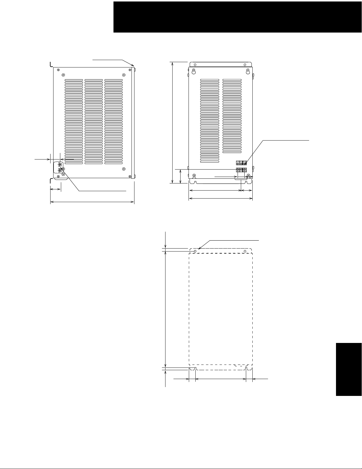
• JUSP-RA12
400V Sigma II Servo Systems
Front cover
1.34
(34)
1.77
(45)
Wire lead-in hole with
Φ
1.30 (Φ33) grommet
13.7 (348)
0.30
19.69 (500)
0.95 (24)
(60)
2.36
8.27 (210)
10.20 (259)
Mounting Hole Diagram
(7.5)
4-M5 Mounting holes
M4 Main circuit terminal
1.50 (38)
1.93
(49)
Approximate Mass: 30.9lb (14kg)
19.09 (485)
0.30
(29.5)
(7.5)
1.16
7.87 (200)
1.16
(29.5)
SGDH
Servo Amplifiers
177
Page 2
400V Sigma II Servo Systems
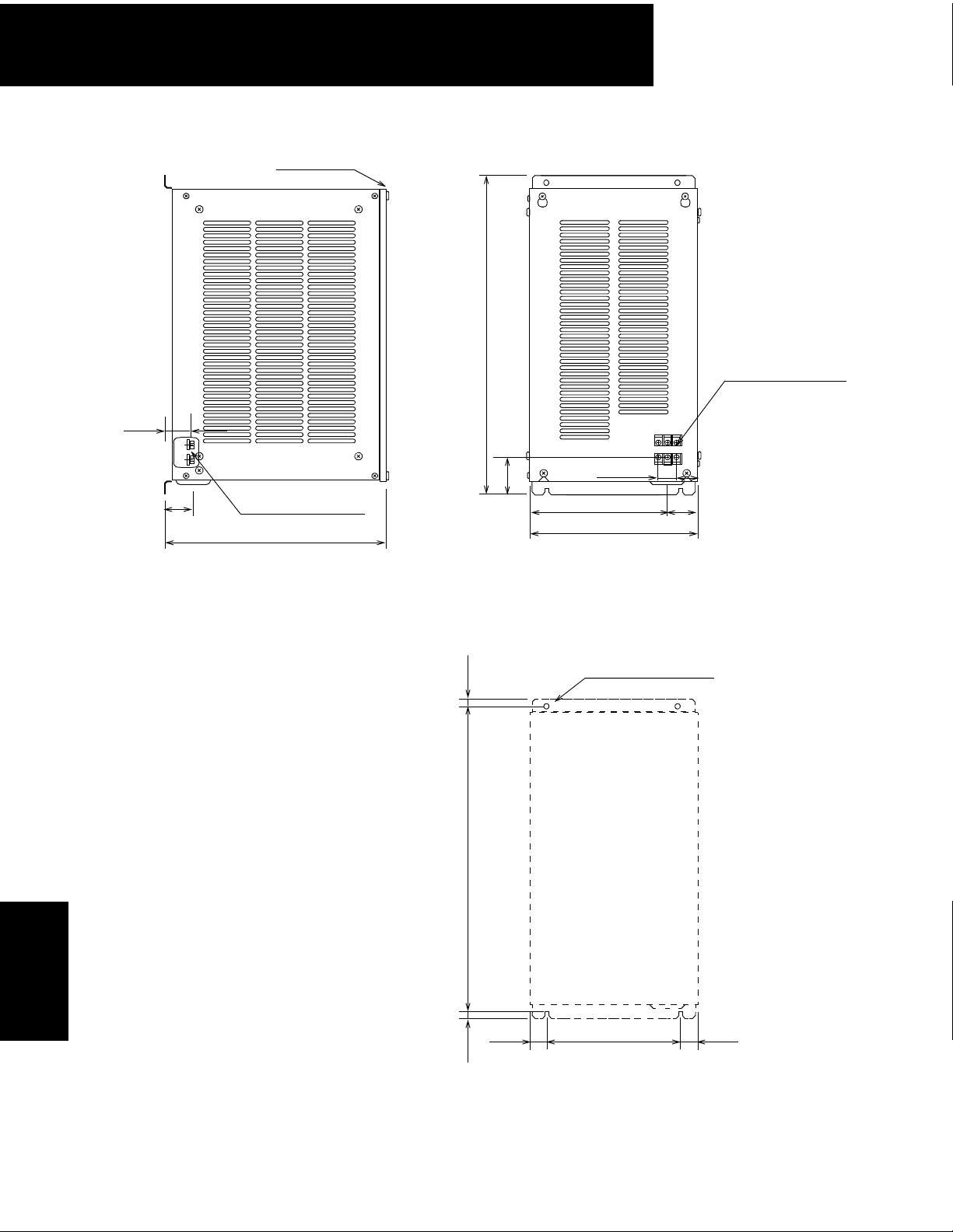
• JUSP-RA13
Front cover
1.46
(37)
1.77
(45)
Wire lead-in hole with
Φ
1.30 (Φ33) grommet
13.7 (348)
0.30
19.69 (500)
1.14 (29)
8.27 (210)
10.20 (259)
2.32
(59)
Mounting Hole Diagram
(7.5)
4-M5 Mounting holes
M8 Main circuit terminal
1.34 (34)
1.93
(49)
Servo Amplifiers
SGDH
178
Approximate Mass: 30.9lb (14kg)
19.09 (485)
0.30
1.16
(29.5)
(7.5)
7.87 (200)
1.16
(29.5)
Page 3
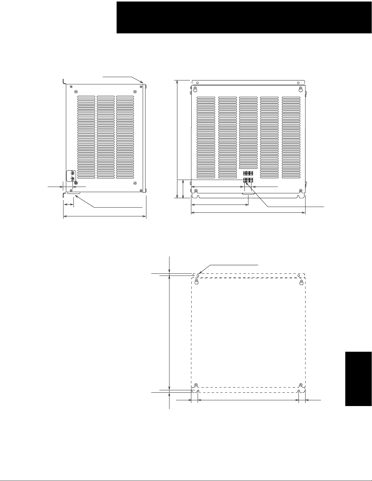
• JUSP-RA14
400V Sigma II Servo Systems
Front cover
19.69 (500)
1.46
(37)
1.77
(45)
Wire lead-in hole with
Φ
1.30 (Φ33) grommet
13.7 (348)
0.30
19.09 (485)
9.09 (231)
(79)
3.11
9.53 (242)
Mounting Hole Diagram
(7.5)
4-M5 Mounting holes
1.14 (29)
M5 Main circuit terminal
19.06 (484)
Approximate Mass: 44.1lb (20kg)
0.30
1.16
(29.5)
(7.5)
16.73 (425)
1.16
(29.5)
SGDH
Servo Amplifiers
179
Page 4

400V Sigma II Servo Systems
• JUSP-RA15
19.69 (500)
1.40
(35.5)
1.77 (45)
Servo Amplifiers
Wire lead-in hole with
Φ
1.30 (Φ33) grommet
13.7 (348)
8.82 (224)
3.09
(78.5)
9.53 (242)
Mounting Hole Diagram
0.30
(7.5)
19.09 (485)
4-M5 Mounting holes
1.50 (38)
M6 Main circuit terminal
19.06 (484)
SGDH
180
Approximate Mass: 47.4lb (21.5kg)
0.30
1.16
(29.5)
(7.5)
16.73 (425)
1.16
(29.5)
Page 5

• JUSP-RA16
400V Sigma II Servo Systems
19.69 (500)
1.40
(35.5)
1.77 (45)
Wire lead-in hole with
Φ
1.30 (Φ33) grommet
13.7 (348)
8.82 (224)
3.09
(78.5)
9.53 (242)
Mounting Hole Diagram
0.30
(7.5)
19.09 (485)
4-M5 Mounting holes
1.50 (38)
M6 Main circuit terminal
19.06 (484)
Approximate Mass: 51.8lb (23.5kg)
0.30
1.16
(29.5)
(7.5)
16.73 (425)
1.16
(29.5)
SGDH
Servo Amplifiers
181
Page 6

400V Sigma II Servo Systems
• Type JUSP-RA18
2 - F0.24 (F6)
mounting holes
13.2 (335)
13.8 (350)
External Regenerative Resistors
Regenerative resistors for servo amplifiers are internally
or externally mounted, as shown in the following table.
They can be mounted externally on all servo amplifiers,
but are especially effective when regenerative energy
exceeds the servo amplifier’s capacity.
0.24 (6)
or SGDH-60DE and 75DE
• Type JUSP-RA19
For SGDH-1A to 1EDE
Servo Amplifiers
SGDH
7.09 (180)
8.66 (220)
9.84 (250)
11.8 (300)
M5 Main
circuit terminal
M5 Main
circuit terminal
M4 Ground terminal
Current resistance
220W 18Ω (x 4 configurable)
Approximate mass: 8.82lb (4kg)
11.8 (30)
13.8 (350)
13.2 (335)
M4 Ground terminal
Current resistance
220W 25.8Ω (x 8 configurable)
11.8 (30)
Approximate mass: 15.4lb (7kg)
3.62 (92)
3.74 (95)
When mounted externally, be sure to remove the jumper
between B2 and B3, which deactivates the internal
regenerative resistor.
Important: External regeneration resistor sizing and
amplifier set-up will be important for proper operation.
Use Yaskawa’s SigmaSize and the Sigma II Series
Servo System User’s Manual: YEA-SIA-S800-32.2
Regenerative Resistor
Mounted in a
Applicable Servo
Amplifier
SGDH-05DE
SGDH-10DE
SGDH-15DE
SGDH-20DE
400V
se
SGDH-30DE
SGDH-50DE
SGDH-60DE
SGDH-75DE
SGDH-1ADE
SGDH-1EDE
Three-pha
Servo Amplifier
Resistance
(Ω)
Wattage*
(W)
108 70
45 140 28 44
32 180 36 28
18** 880** 180 18
14.25*** 1760*** 350 14.2
* Capacity prior to derating. If regeneration power require-
ments exceed internal capacity of the amp, install an external regeneration resistor (reference: Minimum allowable
resistance). Be sure to derate wattage of external resistor
to 20% or less (natural convection) and of 50% or less with
forced air cooling.
** Provided externally by JUSP-RA18
*** Provided externally by JUSP-RA19
Internal
Regenerati
on
Power
Capacity
(W)
14
Minimum
Allowable
Resistance
(Ω)
73
182
Page 7

400V Sigma II Servo Systems
DB Units (For large capacity servo systems)
Externally attach a DB unit to the servopack.
This DB unit is used for dissipating motor EMF energy.
The DB unit does not need to be installed if the dynamic brake function is not required.
• Specifications
Use one of the following DB units according to the servopack model.
Servopack Model SDGH- 2BDE 3ZDE 3GDE 4EDE 5EDE
Regenerative DB Unit JUSP- DB03 DB04 DB05 DB06
DB contactor and surge
absorption unit
Resistance 0.8Ω
Resistance Capacity 180W 300W
Allowable Load Moment of
Inertia
Allowable Duty Less than 1 time/H at maximum speed DB operation.
Built into servopack Built into DB unit
5 times the load moment of inertia at motor shaft.
183
SGDH
Servo Amplifiers
Page 8

400V Sigma II Servo Systems
• JUSP-DB03 Dynamic Brake Unit
• JUSP-DB04 Dynamic Brake Unit
Servo Amplifiers
SGDH
184
Page 9

• JUSP-DB05 Dynamic Brake Unit
400V Sigma II Servo Systems
• JUSP-DB06 Dynamic Brake Unit
SGDH
Servo Amplifiers
185
Page 10

400V Sigma II Servo Systems
Control of Harmonic Frequency in the Power Supply Circuit
If harmonic frequency control is needed in the power supply, connect a DC reactor between terminals
(+) 1 and (+) 2 on the servo amplifier’s main circuit. Use the following table as a guide for selection of
the appropriate reactor.
Reactor Specifications
Applicable Servo Amplifier
Impedance
(mH)
Rated Current
(A)
Reactor Model
SGDH-05DE
SGDH-10DE
SGDH-15DE
400V
SGDH-20DE
SGDH-30DE
SGDH-50DE 1.5 14.1 X5077
Larger size amplifiers
• DC Reactor Dimensional Drawings
12
4 − ΦH
4.7
3.3
2.2
—
B
A
ΦJ
D
C
1.5 X5074
4.5 X5075
8.6 X5076
— Consult factory for availability
G
E
F
Servo Amplifiers
SGDH
186
Reactor
Model
X5074
X5075
X5076
X5077 Consult factory
A B C D E F G ΦH ΦJ
1.18
(30)
1.57
(40)
1.97
(50)
1.85
(47)
2.32
(59)
2.91
(74)
2.76
(70)
3.94
(100)
4.92
(125)
Dimensions
in (mm)
3.35851.10281.50381.77
4.72
(120)
5.51
(140)
1.57
(40)
1.38
(35)
1.97
(50)
1.77
(45)
(45)
2.17
(55)
2.36
(60)
0.16
(4)
0.20
(5)
0.17
(4.3).
Approximate
Mass
lb (kg)
0.661
(0.3)
1.984
(0.9)
2.43
(1.1)
 Loading...