

400V Sigma II Servo Systems
Dimensions in inches (mm)
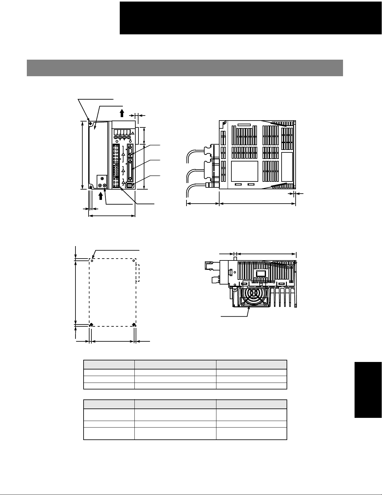
SGDH Servo Amplifier
• SGDH-05DE, -10DE, -15DE (400V Three-phase, 0.5kW to 1.5kW)
2-Φ0.20 (Φ5) holes
Heat sink
Air flow
YASKAWA
8 8 8 88
MODE/SET
6.30 (160)
Ground terminal
2 x M4 screws
0.20 (5)
Air flow
4.33 (110)
Mounting Hole Diagram
2 x M4 screw holes
0.22
(5.5)
0.31 (8)
SGDH
DATA/
CHARGE
POWER
C
L1
N
3
L2
⊕
1
⊕
2
C
N
1
L1C
L2C
B1
B2
U
V
C
W
N
2
(39)
4.17 (106) 1.54
Terminal
block
(3 types)
CN3
CN1
CN2
2.95 (75)
0.16 (4)
7.09 (180)
5.57 (141.5)0.28 (7)
(Mounting pitch)
Cooling fan
5.89 (149.5) ±0.020 (0.5)
(5)
0.20
3.94 (100) ±0.020 (0.5)
0.20
(5)
(Mounting pitch)
0.20
(5)
Approximate mass: 6.17lb (2.8kg)
Connectors on the amplifier (supplied):
Connector Symbol Servo Amplifier Receptacle Manufacturer
CN1 10250-52A2JL 3M Company
CN2 53460-0611 Molex Co.
CN3 10214-52A2JL 3M Company
User needs to obtain the following:
Connector Symbol Mating Connector Manufacturer
1CN
10150-3000VE connector
10350-52A0-008 case
2CN 55100-0600 Molex Co.
3CN
JEZ-9S connector
J-C9-2C case
3M Company
JST Company
SGDH
Servo Amplifiers
167
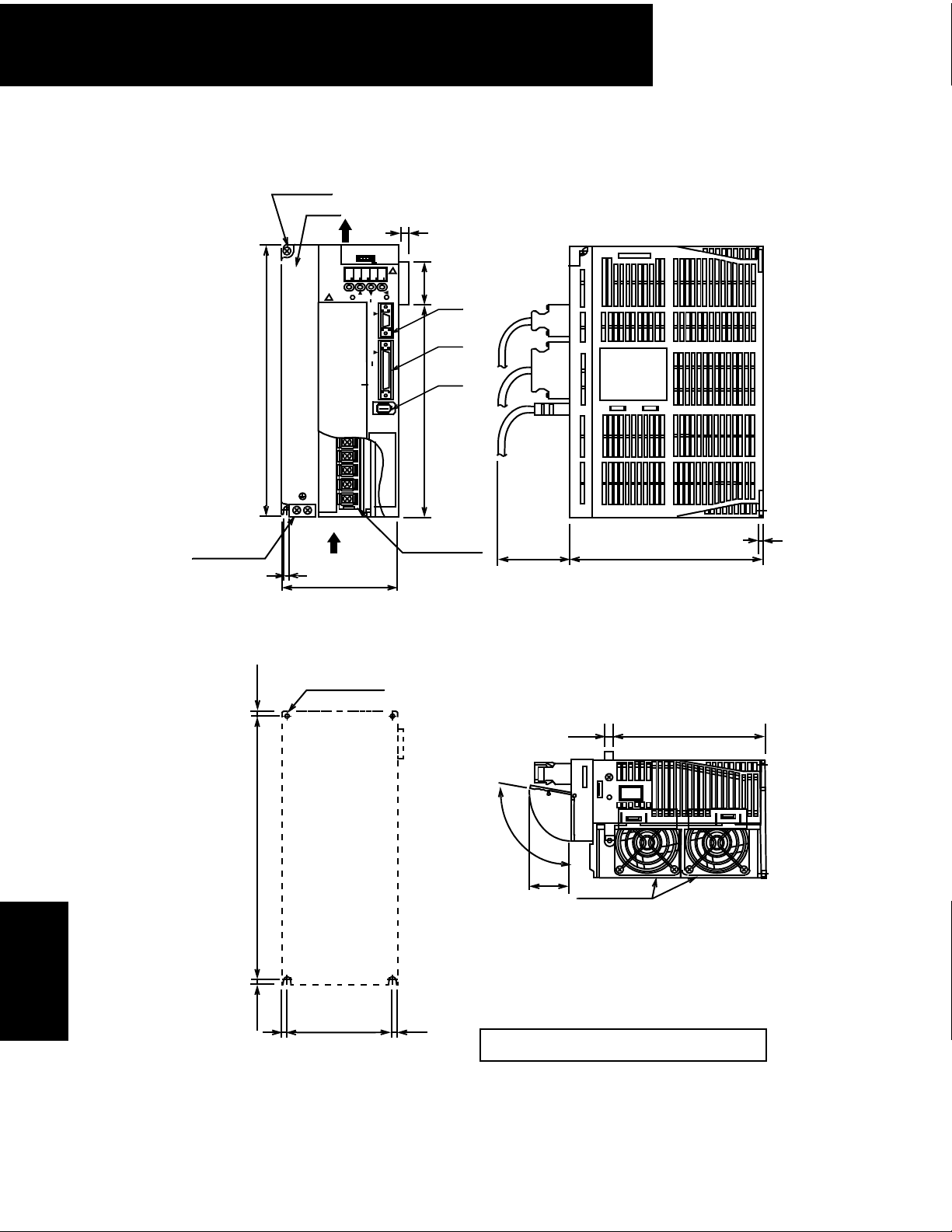
400V Sigma II Servo Systems
• SGDH-20DE, 30DE (400V Three-phase, 2.0kW, 3.0kW)
2-Φ0.24 (Φ6) holes
Heat sink
Air flow
YASKAWA
8 8 8 88
MODE/SET
CHARGE
SERVOPACK
SGDH
CN3
DATA/
POWER
0.315 (8)
(39)
1.54
CN3
9.84 (250)
B2
B3
U
V
W
Ground terminal
2 x M4 screws
0.24 (6)
4.33 (110)
Mounting Hole Diagram
4 x M5 screw holes
(6)
0.24
Air
flow
CN1
CN2
7.72 (196)
14-pin terminal
M4 mounting screws
CN1
CN2
0.16 (4)
7.09 (180)2.95 (75)
5.57 (141.5)0.28 (7)
Servo Amplifiers
SGDH
168
9.39 (238.5) ±0.020 (0.5)
0.22
(Mounting pitch)
(5.5)
0.20
(5)
3.94 (100)
±
0.020 (0.5)
(Mounting pitch)
0.20
(5)
(100°)
1.57
Cooling fan
(40)
Approximate mass: 8.38lb (3.8kg)
Mating connectors: See page 167
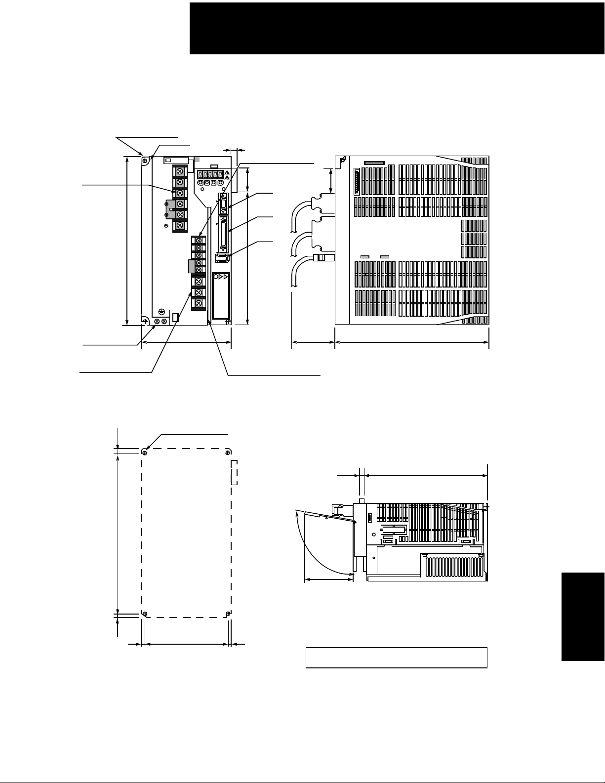
• SGDH-50DE (400V Three-phase, 5.0kW)
400V Sigma II Servo Systems
2 Φ0.24 (Φ6) hole
6-pin terminal
M5 mounting screw
Heat sink
L1
L2
L3
9.84 (250)
Ground terminal
2 × M4 screws
3-pin terminal
M5 mounting screw
Mounting Hole Diagram
1
2
L1C
L2C
B1
B2
B3
U
V
W
5.31 (135)
0.31 (8)
YASKAWA SERVOPACK 200V
SGDH-50AE
Ver.
MODE/SET
CHARGE POWER
5-pin terminal
M6 mounting screw
DATA/
C
N
3
C
N
1
(39)
1.54
CN3
CN1
CN2
C
N
2
Cover (not shown) hinges
from this line, closing over
the left side of the front.
2.95 (75)
9.06 (230)
0.24
9.39 (238.5?) ±0.020? (0.5?)
0.22
(6)
Mounting pitch
(5.5)
0.20
(5)
4 x M5 screw holes
4.92 (125)
(Mounting pitch)
0.20
(5)
7.54 (191.5)0.28 (7)
(
1
0
0
°
)
3.27 (8.3)
Approximate mass: 12.12lb (5.5kg)
Mating connectors: See page 167
SGDH
Servo Amplifiers
169

400V Sigma II Servo Systems
• SGDH-60DE, SGDH-75DE (400V Three-phase, 6.0kW, 7.5kW)
4.33 (110)
11.13 (282.6)
4.61 (117) 1.81 (46)
(32)
1.26
L1 L2 L3
(7)
0.28
0.28 (7)
1.2 (30.7)
6.22 (158)
M4 Control circuit terminal
M5 Main circuit terminal
CN1
−
+
–
+
+
maximum
8.8.8.8.8
.
CN8
CN5
CN2
B1 B2 U V W
9.05 (230)
0.31
(8)
13.78 (350)
0.79
(20)
1.11
(28.3)
M8 Ground terminal
CN10
Control
Circuit
Terminal
Main circuit/
Control circuit
Terminal
0.39
(10)
(39)
1.54
8.31 (211.1)
0.94
4.76 (121)
(24)
Ground terminal
Cooling fan
maximum
Air flow
3.54(90)
9.25 (235)
Air flow
Servo Amplifiers
SGDH
Mounting Hole Diagram::
(7.5)
0.295
13.19 (335)
0.98
0.295
(7.5)
(25)
7.09 (180)
0.98
(25)
8.74 (22)
5.04 (128)
4.09 (104)
Approximate mass: 29.8lb (13.5kg)
Mating connectors: See page 167
170

400V Sigma II Servo Systems
• SGDH-1ADE, SGDH-1EDE (400V Three-phase, 11.0kW, 15.0kW)
SERVOPACK 200V
SGDH—
Ver.
YASKAWA
5.51 (140)
maximum 17.72 (450)
12.60 (320)
M4 Control
circuit terminal
L1 L2 L3 +1
1.42 (36)
0.28
(7)
5.28 (134)
0.35 (9)
M5 Main circuit terminal
Mounting Hole Diagram
0.295
(7.5)
CN3
+2
10.55 (268)
8.8.8.8.8
.
DATA
CN2
CN1
M4 Mounting screws
B1 B2 U V W
2.05 (52)
2.91 (74)
M8 Ground terminal
A
0.31
(8)
0.28
(7)
0.295
0.295
(7.5)
17.13 (435)
(7.5)
0.94(24)
View A:
0.28 (7)
0.39 (10)
1.54
0.75
(19)
Main/Control circuit terminal
M8 Ground terminal
Cooling fan
9.69 (246)
(39)
CN10
4.62 (117)
11.12 (285)
Air flow
0.68 (17)
4.92 (125)
Air flow
17.13 (435)
0.295
(7.5)
1.18
(30)
0.28 (7)
7.87 (200)
1.18
(30)
8.23 (209)
5.59 (142)
5.59 (142)
Approximate mass: 31.53lb (14.3kg)
Mating connectors: See page 167
10.67 (271)
8.74 (2.22)
SGDH
Servo Amplifiers
171

400V Sigma II Servo Systems
• SGDH-2BDE ( 400V Three-phase, 22kW)
18.07 (459)
2.56
(65)
14.56 (370)
19.69 (500)
Control circuit
connector
14.56 (370)
3CN
Front cover
5.59
(142)
Cooling fan
Air flow
2.56
M8 Main circuit terminal
(65)
Mounting Hole Diagram
4-M8 Mounting holes
18.70 (475)
2CN1CN
14.56 (370)
Ground terminal
2 x M8 screws
Note: Dimensions are for positioning of application
module. Unlike other Sigma II amplifiers, the male
connector is inset into the amplifier so that it does
not protrude past the outside edge.
4.57
(116)
6.61 (152)
12.01 (305)
13.70 (348)
Approximate Mass: 88.2lb (40kg)
Mating connectors: See page 167
Servo Amplifiers
SGDH
172
0.49 0.49
(12.5) (12.5)
0.98
(25)
12.60 (320)
0.98
(25)

400V Sigma II Servo Systems
• SGDH-3ZDE( 400V Three-phase, 30kW)
18.07 (459)
2.56
(65)
14.56 (370)
Control circuit
connector
14.56 (370)
19.69 (500)
2.56
M8 Main circuit terminal
(65)
3CN
2CN1CN
14.56 (370)
Ground terminal
2 x M8 screws
Mounting Hole Diagram
Front cover
5.59
(142)
4.57
(116)
Cooling fan
Air flow
6.61 (152)
12.01 (305)
13.70 (348)
18.70 (475)
0.98
(25)
0.49 0.49
(12.5) (12.5)
4-M8 Mounting holes
12.60 (320)
Note: Dimensions are for positioning of application
module. Unlike other Sigma II amplifiers, the male
connector is inset into the amplifier so that it does
not protrude past the outside edge.
Approximate Mass: 82.2lb (40kg)
Mating connectors: See page 167
0.98
(25)
SGDH
Servo Amplifiers
173

400V Sigma II Servo Systems
• SGDH-3GDE ( 400V Three-phase, 37kW)
(65)
3.56
Control circuit
connector
14.56 (370)
19.69 (500)
1CN
(65)
2.56
M8 Main circuit terminal
Mounting Hole Diagram
0.49
(12.5)
23.19 (589)
3CN
2CN
19.69 (500)
Front cover
Ground terminal
2 x M8 screws
Note: Dimensions are for positioning of application
module. Unlike other Sigma II amplifiers, the male
connector is inset into the amplifier so that it does
not protrude past the outside edge.
Cooling fan
Air flow
5.59
(142)
4.57
(116)
6.87 (174.5)
12.07 (306.5)
13.70 (348)
Servo Amplifiers
SGDH
174
18.70 (475)
0.98
(25)
0.49
(12.5)
4-M8 Mounting holes
18.37 (450)
Approximate Mass: 132.3lb (60kg)
Mating connectors: See page 167
0.98
(25)

400V Sigma II Servo Systems
• SGDH-4EDE ( 400V Three-phase, 45kW)
• SGDH-5EDE ( 400V Three-phase, 55kW)
(65)
2.56
Control circuit Connector for operator
connector
14.56 (370)
19.69 (500)
2CN
1CN
(65)
2.56
M10 Main circuit terminal
Mounting Hole Diagram
25.16 (639)
3CN
21.65 (550)
Front cover
Ground terminal
2 x M8 screws
Cooling fan
Air flow
5.59
(142)
4.57
(116)
6.87 (174.5)
12.07 (306.5)
13.70 (348)
0.49
(12.5)
Note: Dimensions are for positioning of application
module. Unlike other Sigma II amplifiers, the male
connector is inset into the amplifier so that it does
not protrude past the outside edge.
4-M8 Mounting holes
Approximate Mass: 143.3lb (65kg)
18.70 (475)
Mating connectors: See page 167
0.98
19.69 (500)
(25)
0.49
(12.5)
0.98
(25)
SGDH
Servo Amplifiers
175
 Loading...