

Page 1

AC Servomotors and Driver
SGMG/SGMS/SGMD/SGM/SGMP Servomotors
SGDB Servopack
YASKAWA
YA S K A WA
MANUAL NO. TSE-S800-16E
Page 2

PREFACE
The rapid progress being made in today’s automation and information
technologies is resulting in a growing need for even more-advanced motion
control for future high-tech equipment. The end result is a need for devices
that can provide more-precise and quicker motion at higher speeds. Servo
control technology makes this possible. Launched by Yaskawa in 1993, the
Σ Series consists of innovative AC Servos that were developed using
leading-edge servo control technology.
This manual covers all products in the Σ Series, which feature superior
functions and performance. This manual was designed to provide
comprehensible information for users who are about to use a servo for the
first time as well as for users who already have experience in using servos.
This manual enables users to understand what Σ-Series AC Servos are all
about and how to design, install, operate, and maintain a servo system.
Keep this manual in a convenient location and refer to it whenever
necessary in operating and maintaining the servo system.
YASKAWA ELECTRIC CORPORATION
General Precautions
S Some drawings in thismanual are shown with the protective cover or shields removed, in order to
describe the detail with more clarity. Make sure all covers and shields are replaced before operating this product.
S Some drawings in this manual are shown as typical example and may differ from the shipped
product.
S This manual may be modified when necessary because of improvement of the product, modifica-
tion or changes in specifications.
Such modification is made as a revision by renewing the manual No.
S To order a copy of this manual, if your copy has been damaged or lost, contact your YASKAWA
representative listed on the last page stating the manual No. on the front cover.
S YASKAWA is not responsible for accidents or damages due to any modification of the product
made by the user since that will void our guarantee.
Page 3

NOTES FOR SAFE OPERATION
Read this manual thoroughly before installation, operation, maintenance or inspection of the AC Servo
Drives. In this manual, the NOTES FOR SAFE OPERATION are classified as “WARNING” or
“CAUTION”.
WARNING
Indicates a potentially hazardous situation which, if not avoided, could result in death or serious personal inju-
ry.
CAUTION
Indicates a potentially hazardous situation which, if not avoided, may result in minor or moderate personal
injury and/or damage to the equipment.
In some instances, items described in
follow these important items.
.
CAUTION
may also result in a serious accident. In either case,
− iv −
Page 4

WARNING
(WIRING)
S Grounding must be in accordance with the national code and consistent
with sound local practices.
Failure to observe this warning may lead to electric shock or fire.
(OPERATION)
S Never touch any rotating motor parts during operation.
Failure to observe this warning may result in personal injury.
(INSPECTION AND MAINTENANCE)
S Be sure to turn OFF power before inspection or maintenance.
Otherwise, electric shock may result.
S Never open the terminal cover while power is ON, and never turn ON pow-
er when the terminal cover is open.
Otherwise, electric shock may result.
S After turning OFF power, wait at least five minutes before servicing the
product.
Otherwise, residual electric charges may result in electric shock.
CAUTION
(RECEIVING)
S Use the specified combination of servomotor and SERVOPACK.
Failure to observe this caution may lead to fire or failure.
(INSTALLATION)
S Never use the equipment where it may be exposed to splashes of water,
corrosive or flammable gases, or near flammable materials.
Failure to observe this caution may lead to electric shock or fire.
(WIRING)
S Do not connect three−phase power supply to output terminals
.
W
Failure to observe this caution may lead to personal injury or fire.
S Securely tighten screws on the power supply and motor output terminals.
Failure to observe this caution can result in a fire.
UV
and
− v −
Page 5

CAUTION
(OPERATION)
S To avoid inadvertent accidents, run the servomotor only in test run (with-
out load).
Failure to observe this caution may result in personal injury.
S Before starting operation with a load connected, set up parameters suit-
able for the machine.
Starting operation without setting up parameters may lead to overrun failure.
S Before starting operation with a load connected, make sure emergency-
stop procedures are in place.
Failure to observe this caution may result in personal injury.
S During operation, do not touch the heat sink.
Failure to observe this caution may result in burns.
(INSPECTION AND MAINTENANCE)
S Do not disassemble the servomotor.
Failure to observe this caution may result in electric shock or personal injury.
S Never change wiring while power is ON.
Failure to observe this caution may result in electric shock or personal injury.
− vi −
Page 6

Manual Contents
This manual providesΣ-Series users with information on the following:
•
An overview of servo systems for first-time users.
•
Checking the product on delivery and basic applications of the servo.
•
Servo applications.
•
Selecting an appropriate servo for your needs and placing an order.
•
Inspection and maintenance.
Manual Structure
All chapters in this manual are classified into one or more of three areas according to their contents: A, B, and
C. Refer to the applicable chapters for the information you require.
A:
Chapters explaining how to select a servo: For users who wish to gain a basic understanding of
Σ
Series products or who need to select an appropriate servo.
B:
Chapters explaining how to design a servo system: For users who are about to design, install, and
operate aΣ-Series Servo Control System.
C:
Chapters explaining maintenance: For users who are going to maintain and troubleshootΣ-Series
products.
Chapter
CHAPTER 1 For First-time Users of AC Servos
CHAPTER 2 Basic Uses of Σ-series Products
CHAPTER 3 Applications of Σ-series Products
CHAPTER 4 Using the Digital Operator
CHAPTER 5 Servo Selection and Data Sheets
CHAPTER 6 Inspection, Maintenance, and Troubleshooting
APPENDIXES
Title Page Area
....................... .........
Provides an overview of servos and theΣSeries.
......................... .........
Describes steps to take when product is received, plus basic
wiring and application methods.
....................... .........
Describes the effective usage ofΣ-Series features according to
application.
.............................. ........
Describes operating procedures forΣ-Series servos, turning
features ON and OFF, setting control constants, etc.
........................ ........
Describes selection methods forΣ-Series servos and peripherals and provides servo specifications.
Describes user maintenance and troubleshooting.
A
Servo Adjustment 539
B
List of I/O Signals 555
C
List of Parameters 561
D
List of Alarm Displays 569
....................................... ........
....................................... ........
....................................... ........
.................................... ........
1
15
51
177
221
........... ........
499
A, B
B
B
B
A, B
C
B, C
B, C
B, C
B, C
INDEX
.............................................................. 573.........
A, B, C
− vii −
Page 7

Basic Terms
Unless otherwise specified, the following definitions are used:
Servomotor:
SERVOPACK: An amplifier (Trademark of Yaskawa servo amplifier “Σ-Series SGDB-jAD
Servodrive: A servomotor and an amplifier (SGDB SERVOPACK)
Servo system: A complete servo control system consisting of servodrive, host controller,
Visual Aids
The following aids are used to indicate certain types of information for easier reference.
.
TERMS
Σ
-Series SGMG/SGMD/SGMS/SGM/SGMP servomotor
SERVOPACK”)
and peripheral devices
Indicates references for additional information.
Technical terms placed in bold in the text are briefly explained in a “TERMS” section at the bottom of the page. The following kinds of technical terms are explained:
Technical terms that need to be explained to users who are not very familiar with
servo systems or electronic devices and technical terms specific toΣSeries Servos that need to be explained in descriptions of functions.
The text indicated by this icon explains the operating procedure using hand-held
type digital operator (Type: JUSP-OP02A-1).
JUSP-OP02A-1
NOTE
The text indicated by this icon explains the operating procedure using mount type
digital operator (Type: JUSP-OP03A).
AΣ-Series Servodrive alone cannot ensure the functionality and performance of the entire
machine control system. It must be combined with an appropriate machine and host controller so that the entire control system works properly. Therefore, carefully read the instruction
manuals for the machine to be used before attempting to operate the servodrive.
− viii −
Page 8

Yaskawa, 1995
All rights reserved. No part of thispublication may be reproduced, stored in aretrieval system, or transmitted, in any form, or
by any means, mechanical, electronic, photocopying, recording, or otherwise, without the prior written permission of Yaskawa. No patent liability isassumed with respect to the use of the informationcontained herein. Moreover,becauseYaskawa
is constantly striving to improve its high-quality products, the information contained in this manual is subject to change
without notice. Every precaution has been taken in the preparation of this manual. Nevertheless, Yaskawa assumes no responsibility for errors or omissions. Neither is any liability assumed for damages resulting from the use of the information
contained in this publication.
− ix −
Page 9

CONTENTS
CHAPTER 1 FOR FIRST-TIME USERS OF AC SERVOS 1...............
1.1 Servo Mechanisms 2.......................................................
1.2 Servo Configuration 5......................................................
1.3 Features of Σ-Series Servos 11................................................
1.3.1 Servomotor Type 11.................................................
1.3.2 Control Type of SERVOPACKs 11......................................
1.3.3 How to Use the SGDB SERVOPACKs 12................................
CHAPTER 2 BASIC USES OF Σ-SERIES PRODUCTS 15.................
2.1 Precautions 16.............................................................
2.1.1 Notes on Use 16....................................................
2.2 Installation 18.............................................................
2.2.1 Checking on Delivery 18..............................................
2.2.2 Servomotors 18.....................................................
2.2.3 SERVOPACKs 22...................................................
2.2.4 Installing the Servomotor 24...........................................
2.2.5 Installing the SERVOPACK 27.........................................
2.3 Connection and Wiring 30....................................................
2.3.1 Connecting to Peripheral Devices 30....................................
2.3.2 Main Circuit Wiring and Power ON Sequence 34..........................
2.3.3 Connection to Host Controller 36.......................................
2.4 Conducting a Test Run 40....................................................
2.4.1 Test Run in Two Steps 40.............................................
2.4.2 Step 1: Conducting a Test Run for Motor without Load 42...................
2.4.3 Step 2: Conducting a Test Run with the Motor Connected to the Machine 46.....
2.4.4 Supplementary Information on Test Run 47...............................
2.4.5 Minimum Parameters Required and Input Signals 49........................
CHAPTER 3 APPLICATIONS OF Σ-SERIES PRODUCTS 51..............
3.1 Setting Parameters According to Machine Characteristics 54.........................
3.1.1 Changing the Direction of Motor Rotation 54..............................
3.1.2 Setting the Overtravel Limit Function 56.................................
3.1.3 Restricting Torque 59................................................
3.2 Setting Parameters According to Host Controller 64................................
3.2.1 Inputting Speed Reference 64..........................................
3.2.2 Inputting Position Reference 68........................................
3.2.3 Using Encoder Outputs 73............................................
3.2.4 Using Contact I/O Signals 77..........................................
3.2.5 Using Electronic Gear 79.............................................
3.2.6 Using Contact Input Speed Control 83...................................
3.2.7 Using Torque Control 87..............................................
3.2.8 Using Torque Feed-forward Function 94.................................
3.2.9 Using Torque Restriction by Analog Voltage Reference 95...................
3.2.10 Using the Reference Pulse Inhibit Function (INHIBIT) 97....................
3.2.11 Using the Reference Pulse Input Filter Selection Function 98.................
3.2.12 Using the Analog Monitor 99..........................................
3.3 Setting Up the Σ SERVOPACK 100.............................................
− x −
Page 10

CONTENTS
3.3.1 Setting Parameters 100................................................
3.3.2 Setting the Jog Speed 101..............................................
3.3.3 Setting the Number of Encoder Pulses 102.................................
3.3.4 Setting the Motor Type 103.............................................
3.3.5 Adjusting the Encoder Supply Voltage 104.................................
3.4 Setting Stop Mode 105.......................................................
3.4.1 Adjusting Offset 105..................................................
3.4.2 Using Dynamic Brake 106.............................................
3.4.3 Using Zero-Clamp 107................................................
3.4.4 Using Holding Brake 108..............................................
3.5 Running the Motor Smoothly 113...............................................
3.5.1 Using the Soft Start Function 113........................................
3.5.2 Using the Smoothing Function 114.......................................
3.5.3 Adjusting Gain 114...................................................
3.5.4 Adjusting Offset 115..................................................
3.5.5 Setting the Torque Reference Filter Time Constant 115.......................
3.6 Minimizing Positioning Time 117...............................................
3.6.1 Using Autotuning Function 117.........................................
3.6.2 Setting Servo Gain 117................................................
3.6.3 Using Feed-forward Control 119.........................................
3.6.4 Using Proportional Control 119.........................................
3.6.5 Setting Speed Bias 120................................................
3.6.6 Using Mode Switch 121...............................................
3.7 Forming a Protective Sequence 127.............................................
3.7.1 Using Servo Alarm Output and Alarm Code Output 127......................
3.7.2 Using Servo ON Input Signal 130........................................
3.7.3 Using Positioning Complete Signal 131...................................
3.7.4 Using Speed Coincidence Output Signal 134...............................
3.7.5 Using Running Output Signal 136.......................................
3.7.6 Using OL Warning and Alarm Output Signals 138...........................
3.7.7 Using Servo Ready Output Signal 140....................................
3.7.8 Handling of Power Loss 141............................................
3.8 Special Wiring 142..........................................................
3.8.1 Wiring Instructions 142................................................
3.8.2 Wiring for Noise Control 144...........................................
3.8.3 Using More Than One Servo Drive 149...................................
3.8.4 Using Regenerative Resistor Units 151....................................
3.8.5 Using an Absolute Encoder 152.........................................
3.8.6 Extending an Encoder Cable 162........................................
3.8.7 Using SGDB SERVOPACK with High Voltage Line 164......................
3.8.8 Connector Terminal Layouts 166........................................
CHAPTER 4 USING THE DIGITAL OPERATOR 177.....................
4.1 Basic Operations 178.........................................................
4.1.1 Connecting the Digital Operator 178.....................................
4.1.2 Digital Operator Functions 179..........................................
4.1.3 Resetting Servo Alarms 180............................................
− xi −
Page 11

CONTENTS
4.1.4 Basic Functions and Mode Selection 181..................................
4.1.5 Operation in Status Display Mode 182....................................
4.1.6 Operation in Parameter Setting Mode 186.................................
4.1.7 Operation in Monitor Mode 191.........................................
4.2 Using the Functions 194......................................................
4.2.1 Operation in Alarm Trace-back Mode 194.................................
4.2.2 Operation Using the Digital Operator 197.................................
4.2.3 Autotuning 201......................................................
4.2.4 Reference Offset Automatic Adjustment 207...............................
4.2.5 Reference Offset Manual Adjustment Mode 210............................
4.2.6 Clearing Alarm Trace-back Data 213.....................................
4.2.7 Checking Motor Specifications 215......................................
4.2.8 Checking Software Version 216.........................................
4.2.9 Current Detection Offset Manual Adjustment Mode 217......................
CHAPTER 5 SERVO SELECTION ANDDATA SHEETS 221................
5.1 Selecting a Σ-Series Servo 223.................................................
5.1.1 Selecting a Servomotor 223............................................
5.1.2 Selecting a SERVOPACK 233...........................................
5.1.3 Selecting a Digital Operator 235.........................................
5.2 SGM Servomotor 237........................................................
5.2.1 Ratings and Specifications 237..........................................
5.2.2 Mechanical Characteristics 269..........................................
5.2.3 Option Specifications 272..............................................
5.3 SERVOPACK Ratings and Specifications 282.....................................
5.3.1 Combined Specifications 282...........................................
5.3.2 Ratings and Specifications 285..........................................
5.3.3 Overload Characteristics 288...........................................
5.3.4 Starting Time and Stopping Time 289.....................................
5.3.5 Load Inertia 290.....................................................
5.3.6 Overhanging Loads 291...............................................
5.4 Σ-Series Dimensional Drawings 292.............................................
5.4.1 Servomotor Dimensional Drawings 292...................................
5.4.2 SERVOPACK Dimensional Drawings 400.................................
5.4.3 Digital Operator Dimensional Drawings 412...............................
5.5 Selecting Peripheral Devices 414...............................................
5.5.1 Selecting Peripheral Devices 414........................................
5.5.2 Order List 424.......................................................
5.6 Specifications and Dimensional Drawings of Peripheral Devices 442...................
5.6.1 Cable Specifications and Peripheral Devices 442............................
5.6.2 Motor Cables 446....................................................
5.6.3 Connector 447.......................................................
5.6.4 Brake Power Supply 466...............................................
5.6.5 Encoder Cables 469...................................................
5.6.6 Battery for Absolute Encoder 480........................................
5.6.7 1CN Connector 481...................................................
5.6.8 Connector Terminal Block Converter Unit 483..............................
− xii −
Page 12

CONTENTS
5.6.9 Cable With 1CN Connector and One End Without Connector 485...............
5.6.10 Circuit Breaker 486...................................................
5.6.11 Noise Filter 486......................................................
5.6.12 Magnetic Contactor 488...............................................
5.6.13 Surge Suppressor 490.................................................
5.6.14 Regenerative Resistor Unit 490..........................................
5.6.15 Variable Resistor for Speed Setting 491...................................
5.6.16 Encoder Signal Converter Unit 492......................................
5.6.17 Cables for Connecting PC and SERVOPACK 494...........................
CHAPTER 6 INSPECTION, MAINTENANCE, AND TROUBLESHOOTING 499.
6.1 Inspection and Maintenance 500................................................
6.1.1 Servomotor 500......................................................
6.1.2 SERVOPACK 501....................................................
6.1.3 Replacing Battery for Absolute Encoder 502...............................
6.2 Troubleshooting 503.........................................................
6.2.1 Troubleshooting Problems with Alarm Display 503..........................
6.2.2 Troubleshooting Problems With No Alarm Display 529.......................
6.2.3 Internal Connection Diagram and Instrument Connection Examples 531.........
A Servo Adjustment 539........................................................
A.1 Σ-Series AC SERVOPACK Gain Adjustment 540..................................
A.1.1 Σ-Series AC SERVOPACKs and Gain Adjustment Methods 540................
A.1.2 Basic Rules for Gain Adjustment 541.....................................
A.2 Adjusting a Speed-control SERVOPACK 542......................................
A.2.1 Adjusting Using Auto-tuning 542........................................
A.2.2 Manual Adjustment 543...............................................
A.3 Adjusting a Position-control SERVOPACK 546....................................
A.3.1 Adjusting Using Auto-tuning 546........................................
A.3.2 Manual Adjustment 547...............................................
A.4 Gain Setting References 551...................................................
A.4.1 Guidelines for Gain Settings According to Load Inertia Ratio 551..............
B List of I/O Signals 555........................................................
C List of Parameters 561........................................................
D List of Alarm Displays 569....................................................
INDEX 573...........................................................
− xiii −
Page 13

FOR FIRST-TIME USERS OF AC SERVOS
1
1
This chapter is intended for first-time users of AC servos. It describes the basic configuration of a servo mechanism and basic technical terms relating to
servos.
Users who already have experience in using a servo should also take a look at
this chapter to understand the features of Σ-Series AC Servos.
1.1 Servo Mechanisms 2.......................
1.2 Servo Configuration 5.....................
1.3 Features of Σ-Series Servos 11................
1.3.1 Servomotor Type 11..................................
1.3.2 Control Type of SERVOPACKs 11.......................
1.3.3 How to Use the SGDB SERVOPACKs 12.................
1
Page 14

FOR FIRST-TIME USERS OF AC SERVOS
1.1 Servo Mechanisms
You may be familiar with the following terms:
• Servo
1
• Servo mechanism
• Servo control system
In fact, these terms are synonymous. They have the following meaning:
A control mechanism that monitors physical quantities such as specified positions.
In short, a servo mechanism is like a servant who does tasks faithfully and quickly according
to his master’s instructions. In fact, “servo” originally derives from the word “servant.”
TERMS
Servo mechanism
According to Japanese Industrial Standard (JIS) terminology, a “servo mechanism” is defined as a mechanism that uses the position, direction, or orientation of an object as a process variable to control a system to follow any changes in a target value (set point).
More simply, a servo mechanism is a control mechanism that monitors physical quantities
such as specified positions. Feedback control is normally performed by a servo mechanism. (Source: JIS B0181)
2
Page 15

1 . 1 Servo Mechanisms
Servo system could be defined in more detail as a mechanism that:
• Moves at a specified speed and
• Locates an object in a specified position
To develop such a servo system, an automatic control system involving feedback control
must be designed. This automatic control system can be illustrated in the following block diagram:
Configuration of Servo System
Specified position
input
Servo
amplifier
Servo
motor
Feedback part
Detector
Controlled
machine
(load)
Machine position
output
This servo system is an automatic control system that detects the machine position (output
data), feeds back the data to the input side, compares it with the specified position (input
data), and moves the machine by the difference between the compared data.
In other words, the servo system is a system to control the output data to match the
specified input data.
If, for example, the specified position changes, the servo system will reflect the changes.
In the above example, input data is defined as a position, but input data can be any physical
quantities such as orientation (angle), water pressure, or voltage.
1
TERMS
Position, speed, force (torque), electric current, and so on are typical controlled values for a
servo system.
The main technical terms used in this manual are as follows:
1) Servo mechanism
2) Servo
Normally, servo is synonymous with servo mechanism. However, because “mechanism” is
omitted, the meaning becomes somewhat ambiguous. Servo may refer to the entire servo
mechanism but may also refer to an integral part of a servo mechanism such as a servomotor
or a servo amplifier. This manual also follows this convention in the use of the term “servo”.
Feedback control
A control that returns process variables to the input side and forms a closed loop. It is also
called closed-loop control.
3
Page 16

1
FOR FIRST-TIME USERS OF AC SERVOS
3) Servo control system
Servo control system is almost synonymous with servo mechanism but places the focus on
system control. In this manual, the term “servo system” is also used as a synonym of servo
control system.
Related Terms Meaning
Servomotor
SERVOPACK Trademark of Yaskawa servo amplifier “SGDB
Servo drive A servomotor and amplifier pair. Also called “servo.”
Servo system A closed control system consisting of a host controller,
General servomotors or Yaskawa SGMj servomotors. In
some cases, a position detector (encoder) is included in a
servomotor.
SERVOPACK.”
servo drive and controlled system to form a servo
mechanism.
Host controller
Reference
Amplifier
(SERVOPACK)
Servo drive
Servomotor
Servo system
Operate
Controlled
system
4
Page 17

1.2 Servo Configuration
The following diagram illustrates a servo system in detail:
1.2 Servo Configuration
Host controller
(5)
Position or
speed
reference
Servo amplifier
Comparator
(Input)
Position or
speed
feedback
Power
amplifier
Detector
(1) Controlled system: Mechanical system for which the position or speed is to be con-
trolled.
This includes a drive system that transmits torque from a servomotor.
(4)
Motor
drive
circuit
Gear
(2)
(3)
servomotor Drive system
(Output)
(1)
Controlled
system
Position
Speed
Movable
table
Ball screw
1
(2) Servomotor: A main actuator that moves a controlled system. Two types are
available: AC servomotor and DC servomotor.
(3) Detector: A position or speed detector. Normally, an encoder mounted on
a motor is used as a position detector.
(4) Servo amplifier: An amplifier that processes an error signal to correct the differ-
ence between a reference and feedback data and operates the
servomotor accordingly. A servo amplifier consists of a
comparator, which processes error signals, and a power amplifier, which operates the servomotor.
(5) Host controller: A device that controls a servo amplifier by specifying a position
or speed as a set point.
5
Page 18

FOR FIRST-TIME USERS OF AC SERVOS
Servo components (1) to (5) are outlined below:
(1) Controlled system
In the previous figure, the controlled system is a movable table for which the position
or speed is controlled. The movable table is driven by a ball screw and is connected to
the servomotor via gears.
So, the drive system consists of:
1
Gears + Ball Screw
This drive system is most commonly used because the power transmission ratio
(gear ratio) can be freely set to ensure high positioning accuracy. However, play in the
gears must be minimized.
The following drive system is also possible when the controlled system is a movable
table:
Coupling + Ball Screw
When the power transmission ratio is 1 :
1, a coupling is useful because it has no
play.
Coupling
Rolling-contact
guide
Ball screw
Rolling-contact
bearing
This drive system is widely used for machining tools.
Housing
Timing Belt + Trapezoidal Screw Thread
A timing belt is a coupling device that allows
the power transmission ratio to be set freely
and that has no play.
A trapezoidal screw thread does not provide
excellent positioning accuracy, so can be
Trapezoidal
screw
thread
treated as a minor coupling device.
Servomotor
Timing belt
To develop an excellent servo system, it is important to select a rigid drive system that
has no play.
Configure the controlled system by using an appropriate drive system for the control
purpose.
TERMS
Drive system
Also called a drive mechanism.
A drive system connects an actuator (such as a servomotor) to a controlled system and
serves as a mechanical control component that transmits torque to the controlled system,
orientates the controlled system, and converts motion from rotation to linear motion and
vice versa.
6
Page 19

(2) Servomotor
(a) DC servomotor and AC servomotor
Servomotors are divided into two types: DC servomotors and AC servomotors.
DC servomotors are driven by direct current (DC). They have a long history. Up
until the 1980s, the term “servomotor” used to imply a DC servomotor.
1.2 Servo Configuration
From 1984, AC servomotors were emerging as a result of rapid progress in microprocessor technology. Driven by alternating current (AC), AC servomotors are
now widely used because of the following advantages:
• Easy maintenance: No brush
• High speed: No limitation in rectification rate
Note however that servomotors and SERVOPACKs use some parts that are subject to mechanical wear or aging. For preventive maintenance, inspect and replace parts at regular intervals.
For details, refer to Chapter 6 Inspection, Maintenance, and Troubleshooting.
(b) AC servomotor
AC servomotors are divided into two types: synchronous type and induction type.
The synchronous type is more commonly used.
For a synchronous type servomotor, motor speed is controlled by changing the
frequency of alternating current.
A synchronous type servomotor provides strong holding torque when stopped, so
this type is ideal when precise positioning is required. Use this type for a servo
mechanism for position control.
1
The following figure illustrates the structure of a synchronous type servomotor:
Rotary disc
Light-emitting
element
Position detector
(encoder)
Light-receiving
element
Armature
wire
Lead wire
Housing
Stator core
Magnet
Front cap
Ball bearing
Shaft
Rotor core
Yaskawa SGMj servomotors are of the synchronous type.
7
Page 20

FOR FIRST-TIME USERS OF AC SERVOS
(c) Performance of servomotor
A servomotor must have “instantaneous power” so that it can start as soon as a
start reference is received.
The term “power rating (kW/s)” is used to represent instantaneous power.
It refers to the electric power (kW) that a servomotor generates per second.
The greater the power rating, the more powerful the servomotor.
1
(3) Detector
A servo system requires a position or speed detector. It uses an encoder mounted on
a servomotor for this purpose.
Encoders are divided into the following two types:
(a) Incremental Encoder
An incremental encoder is a pulse generator, which generates a certain number
of pulses per revolution (e.g., 2,000 pulses per revolution). If this encoder is connected to the mechanical system and one pulse is defined as a certain length
(e.g., 0.001 mm), it can be used as a position detector.
However, this encoder does not detect an absolute position and merely outputs a
pulse train. Zero point return operation must be performed before positioning.
The following figure illustrates the operation principle of a pulse generator:
Phase A pulse train
Phase B pulse train
Fixed slit
Light-receiving
element
Rotary slit
Center of
revolution
Phase A
Phase B
Phase Z
Rotary
disc
Slit
Light-emitting
element
(b) Absolute encoder
An absolute encoder is designed to detect an absolute angle of rotation as well as
to perform the general functions of an incremental encoder. With an absolute encoder, therefore, it is possible to create a system that does not require zero point
return operation at the beginning of each operation.
• Difference between an absolute
An absolute
encoder will keep track of the motor shaft position even if system
and incremental encoder:
power is lost and some motion occurs during that period of time. The incremental
encoder is incapable of the above.
8
Page 21

(4) Servo amplifier
A servo amplifier is required to operate an AC servomotor.
The following figure illustrates the configuration of a servo amplifier:
Servo amplifier
1.2 Servo Configuration
Motor driving AC power
Servomotor
Commercial AC power
Reference
input
Comparator
Feedback
Power
amplifier
A servo amplifier consists of the following two sections:
(a) Comparator
A comparator consists of a comparison function and a control function. The comparison function compares reference input (position or speed) with a feedback
signal and generates a differential signal.
1
TERMS
The control function amplifies and transforms the differential signal. In other
words, it performs proportional (P) control or proportional/integral (PI) control.
(It is not important if you do not understand these control terms completely at this
point.)
(b) Power amplifier
A power amplifier runs the servomotor at a speed or torque proportional to the
output of the comparator. In other words, from the commercial power supply of
50/60 Hz, it generates alternating current with a frequency proportional to the reference speed and runs the servomotor with this current.
Proportional/integral (PI) control
PI control provides more accurate position or speed control than proportional control, which
is more commonly used.
9
Page 22

1
FOR FIRST-TIME USERS OF AC SERVOS
(5) Host controller
A host controller controls a servo amplifier by specifying a position or speed as a set
point.
For speed reference, a position control loop may be formed in the host controller when
a position feedback signal is received. Yaskawa MP920 is a typical host controller.
10
TERMS
MP920
A machine controller. If combined with a servo amplifier
for speed control (maximum 44 axes control), the MP920
can provide position control.
The MP920 also provides programmable controller functions.
Page 23

1.3 Features ofΣ-Series Servos
This section describes the features of Σ-Series servos.
1.3.1 Servomotor Type
1.3 Features ofΣ -Series Servos
Σ-Series SGMj servomotors are synchronous type servomotors and have the following
features:
Rated rotation speed
Maximum rotation speed
SGMG
SGMS 3000 r/min
SGMD 2000 r/min
SGM 3000 r/min
SGMP 3000 r/min
1500 r/min
3000 r/min
1000 r/min
2000 r/min
4500 r/min
3000 r/min
4500 r/min
4500 r/min
1.3.2 Control Type of SERVOPACKs
Rated output
0.45 to 15 kW
(10 models)
0.3 to 6.0 kW
(8 models)
1.0 to 5.0 kW
(6 models)
2.2 to 4.0 kW
(3 models)
0.4 to 0.8 kW
(2 models)
0.4 to 1.5 kW
(3 models)
1
SGMG type
SGMP type
SGDB model SERVOPACKs allow the control of speed, position and torque.
• Speed control (analog reference)
Accepts an analog voltage speed reference.
• Speed control (contact reference)
There are 3 internally set speeds. One of
these is selected as a reference by a contact.
• Position control (pulse reference)
Accepts a pulse train position reference
• Torque control (analog reference)
Accepts an analog voltage torque reference
SGDB SERVOPACK
11
Page 24

FOR FIRST-TIME USERS OF AC SERVOS
1.3.3 How to Use the SGDB SERVOPACKs
1.3.3 How to Use the SGDB SERVOPACKs
J Using SERVOPACK for Speed Control
The most common use of a SERVOPACK for speed control is shown below:
Host controller
1
Position reference +
Position control loop
Position
feedback
(Analog
voltage)
Speed
reference
Position
Speed
Convert
Position feedback
SERVOPACK
(speed control mode)
Power
amplifier
Servomotor
Torque
(current)
feedback
Pulse train
Encoder
As shown in the above figure, a position control loop is formed in the host controller. The
host controller compares a position reference with a position feedback signal and sends
the processed result to the SERVOPACK as a speed reference.
In this way the host controller can be freed from performing the servo mechanism control.
The SERVOPACK undertakes the speed control loop and subsequent control processing.
12
The Yaskawa programmable machine controller MP920 is used as a typical host controller.
Page 25

J Using SERVOPACK for Torque Control
SERVOPACK for torque control can be used as shown below:
Host controller
Position
monitoring
Position
information
Torque
reference
(Analog
voltage)
Position feedback Encoder
SERVOPACK
(torque control mode)
Power
amplifier
Torque
(current)
feedback
Pulse train
1.3 Features ofΣ -Series Servos
1
Servomotor
The host controller outputs a torque reference to control the SERVOPACK. It also receives a pulse train (position information) from the SERVOPACK and uses it to monitor
the position.
J Using SERVOPACK for Position Control
SERVOPACK for position control can be used as shown below:
Host controller
Position
monitoring
Position
reference
Position
information
Pulse
train
Speed/current loop
Position feedback
SERVOPACK
(position control mode)
Power
amplifier
Servomotor
Pulse train
Encoder
13
Page 26

FOR FIRST-TIME USERS OF AC SERVOS
1.3.3 How to Use the SGDB SERVOPACKs cont.
The host controller can send a position reference (pulse train) to the SERVOPACK to perform positioning or interpolation.
This type of SERVOPACK contains a position control loop.
Parameters can be used to select either of the following pulse trains:
(1) Code and pulse train
1
(2) Two-phase pulse train with 90° phase difference
(3) Forward and reverse pulse trains
The host controller receives a pulse train (position information) from the SERVOPACK
and uses it to monitor the position.
J Setting Parameters
A Digital Operator can be used to set parameters for a SERVOPACK as follows:
• Setting parameters to enable or disable each function
• Setting parameters required for functions to be used
Set parameters according to the servo system to be set up.
14
Page 27

BASIC USES OF Σ-SERIES
PRODUCTS
This chapter describes the first things to do whenΣ-Series products are delivered. It also explains the most fundamental ways ofconnecting and operating
-Series products. Both first-time and experienced servo users
Σ
this chapter.
2.1 Precautions 16.............................
2.2 Installation 18.............................
2
2
must read
2.1.1 Notes on Use 16.....................................
2.2.1 Checking on Delivery 18...............................
2.2.2 Servomotors 18......................................
2.2.3 SERVOPACKs 22....................................
2.2.4 Installing the Servomotor 24............................
2.2.5 Installing the SERVOPACK 27..........................
2.3 Connection and Wiring 30...................
2.3.1 Connecting to Peripheral Devices 30.....................
2.3.2 Main Circuit Wiring and Power ON Sequence 34............
2.3.3 Connection to Host Controller 36........................
2.4 Conducting a Test Run 40...................
2.4.1 Test Run in Two Steps 40..............................
2.4.2 Step 1: Conducting a Test Run for Motor without Load 42....
2.4.3 Step 2: Conducting a Test Run with the Motor Connected to the
Machine . . . . . . . . . . . . . . . . . . . . . . . . . . . . . . . . . . . . . . . . . 46
2.4.4 Supplementary Information on Test Run 47................
2.4.5 Minimum Parameters Required and Input Signals 49.........
15
Page 28

BASIC USES OF Σ-SERIES PRODUCTS
2.1.1 Notes on Use
2.1 Precautions
This section provides notes on using Σ-Series products.
2.1.1 Notes on Use
NOTE Always note the following to ensure safe use.
2
Use 200VAC power supply
Be sure to use the correct type. Do not plug the
servomotor directly into the power frequency supply (Direct connection to the power frequency
supply will damage the servomotor.)
200VAC
power supply
Always use the SGMj servomotor and SGDB SERVOPACK in pairs.
Check whether the combination of applicable motor series of SERVOPACK and of SGMj ( motor
series) is correct or not. Check the setting of parameter Cn-2A (motor selection) and always after
changing its combination. The motor may get
Recheck the setting
of parameter Cn-2A
(motor selection) after
changing its combination.
Refer to Section 3.3.4.
damaged if the combination is not correct.
Do not change wiring when power is ON.
Direct
connection
Damage will result!
16
Always turn the power OFF before connecting or
disconnecting a connector.
(Except for Digital Operator (Types: JUSPOP02A-1, JUSP-OP03A))
OFF
(POWER and
CHARGE lamp)
Always turn the power
OFF before connecting or disconnecting a
connector.
Note that residual voltage still remains in the SERVOPACK even after the power is
turned OFF.
Even after the power is turned OFF, residual electric charge still remains in the capacitor inside the
SERVOPACK. To prevent an electric shock, always wait for the CHARGE lamp to go OFF before
starting inspection (if necessary).
CHARGE lamp
Page 29

2 . 1 Precautions
Always follow the specified installation method.
Provide sufficient clearance
The SERVOPACK generates heat. Install the
SERVOPACK so that it can radiate heat freely.
Note also that the SERVOPACK must be in an en-
50 mm
or
more
vironment free from condensation, vibration and
shock.
Ambient
temperature:
0to55°C
Perform noise reduction and grounding properly.
If the signal line is noisy, vibration or malfunction
will result.
D Separate high-voltage cables from low-voltage cables.
D Use cables as short as possible.
D Ground the SERVOPACK ground terminal with the
resistance 100Ω or less for the servomotor and
SERVOPACK.
D Never use a line filter for the power supply in the
motor circuit.
Casing
SERVOPACK
Signal
Conduct a voltage resistance test under the following conditions.
D Voltage: 1500 Vrms AC, one minute
D Current limit: 100 mA
D Frequency: 50/60 Hz
D Voltage application points: Between r, t, R, S, T
terminals and frame ground (connect terminals
securely).
line
100 Ω or less
Conduct a voltage
resistance test
under the conditions given on the
left.
10 mm
or
more
Servomotor
2
Use a fast-response type ground-fault interrupter.
For a ground-fault interrupter, always use a fastresponse type or one designed for PWM inverters. Do not use a time-delay type.
Fast-response
type
Ground-fault interrupter
GOOD POOR
GOOD
For PWM
inverter
Do not perform continuous operation under overhanging load.
Continuous operation cannot be performed by rotating the motor from the load and applying regen-
Servomotor
erative braking. Regenerative braking by the
SERVOPACK can be applied only for a short period, such as the motor deceleration time.
Do not apply regenerative
braking continuously.
The servomotor cannot be operated by turning the power ON and OFF.
Frequently turning the power ON and OFF causes
the internal circuit elements to deteriorate. Always
start or stop the servomotor by using reference
pulses.
Power
supply
Time-delay
type
SERVOPACK
Do not start or stop by
turning power ON and OFF.
17
Page 30

BASIC USES OF Σ-SERIES PRODUCTS
2.2.2 Servomotors
2.2 Installation
This section describes how to check Σ-Series products on delivery and how to install them.
2.2.1 Checking on Delivery
When Σ-Series products are delivered, check the following items:
2
Check Items
Check if the delivered products are
the ones you ordered.
Check if the motor shaft rotates
smoothly.
Check for damage. Check the overall appearance, and check for damage
Check screws for looseness. Check for looseness by using a screwdriver as
If any of the above items are faulty or incorrect, contact the dealer from which you purchased the products or your nearest local sales representative.
2.2.2 Servomotors
J External Appearance and Nameplate Examples
Remarks
Check the types marked on the nameplates of
servomotor and SERVOPACK (see the table below).
If the motor shaft is smoothly turned by hand, it is
normal. However, if the motor has brakes, it cannot be
turned manually.
or scratches resulting from transportation.
necessary.
Rated output
Servomotor model
18
Σ-II Series Servomotor
Serial number
Manufacturing date
Rated motor speed
Page 31

J Model Numbers
y
y
Standard Servomotors
2.2 Installation
SGM S − 10 A 6 A
Σ Series servomotor
Series name of products
G: SGMS
S: SGMS
D: SGMD
Motor capacity
(See the following table.)
Standard
A: YASKAWA Standard
Encoder specifications
(See the following table.)
Servomotor Capacity (kW)
Symbol SGMG SGMS SGMD
1500 min−11000 min−13000 min−12000 min
03
05
06
09
10
12
13
15
20
22
− 0.3 − −
0.45 − − −
− 0.6 − −
0.85 0.9 − −
− − 1.0 −
− 1.2 − −
1.3 − − −
− − 1.5 −
1.8 2.0 2.0 −
− − − 2.2
j j
Option specifications
B: 90 VDC Brake
C: 24 VDC Brake
S: Oil seal
F: 90 VDC Brake Oil seal
G: 24 VDC Brake Oil seal
Shaft Specifications
A: Standard (straight without key,
with option specification)
B: Straight with key,
shaft end tap (one place)
C: Taper 1/10, with parallel key
D: Taper 1/10, with semicircle key
(For G series 05, 09 type only)
Rated rotation speed
A: SGMG 1500 min
SGMS 3000 min
SGMD 2000 min
B SGMG 1000 min
Symbol
−1
1500 min−11000 min−13000 min−12000 min
30
32
40
44
50
55
60
75
1A
1E
SGMG SGMS SGMD
2.9 3.0 3.0 −
− − − 3.2
− − 4.0 4.0
4.4 4.4 − −
− − 5.0 −
5.5 − − −
− 6.0 − −
7.5 − − −
11 − − −
15 − − −
−1
−1
−1
−1
−1
2
Encoder Specifications
Code Specification SGMG SGMS SGMD
8192 P/R incremental Optional Standard Optional
2
4096 P/R incremental Standard Optional Optional
6
12-bit absolute Optional Optional Standard
W
15-bit absolute Optional Optional Optional
S
NOTE
Refer to Section 5.1.1 Selecting a Servomotor for the SGMP-15A type.
19
Page 32

BASIC USES OF Σ-SERIES PRODUCTS
y
y
2.2.2 Servomotorscont.
Servomotors with Gears
2
SGM G − 05 A 2 A S A R
Σ-Series servomotor
Series name
G: SGMG
S: SGMS
Motor capacity
(See the following table.)
Standard
A: YASKAWA Standard
Encoder specifications
(See the following table.)
Rated rotation speed
A: SGMG 1500 min
SGMS 3000 min
B: SGMG 1000 min
Symbol SGMG SGMS
03
05
06
09
10
12
13
15
20
−1
−1
−1
Motor Capacity (kW)
1500 min
−1
1000 min
− 0.3 −
0.45 − −
− 0.6 −
0.85 0.9 −
− − 1.0
− 1.2 −
1.3 − −
− − 1.5
1.8 2.0 2.0
−1
3000 min
j
Brake specifications
Blank: Without brake
B: With 90 VDC brake
C: With 24 VDC brake
Shaft specifications
(See the following table.)
Gear ratio
(See the following table.)
Gear type (See the following table.)
−1
Symbol
1500 min
30
40
44
50
55
60
75
1A
−
SGMG SGMS
−1
1000 min
−1
3000 min
2.9 3.0 3.0
− − 4.0
4.4 4.4 −
− − 5.0
5.5 − −
− 6.0 −
7.5 − −
11 − −
− − −
−1
20
Encoder Specifications
Code Specification SGMG SGMS
8192 P/R incremental Optional Standard
2
4096 P/R incremental Standard Optional
6
12-bit absolute Optional Optional
W
15-bit absolute Optional Optional
S
Gear Type
Code Specification SGMG SGMS
With foot Standard
S
Flange Standard
T
IMT planetary low-backlash gear Standard Standard
L
Page 33

Gear Ratio (Varies with Gear Type.)
Code Specification SGMG SGMS
1/6 S, T*
A
1/11 S, T
B
1/21 S, T
C
1/5 L L
1
1/9 L L
2
1/20 L* L
5
1/29 or 1/33 L, S, T* L*
7
1/45 L* L*
8
* Not all applicable models available.
2.2 Installation
Shaft Specifications (Varies with Gear Type.)
Code Specification SGMG SGMS
Straight, with key L L
K
Straight, with key and tap S, T
R
2
21
Page 34

BASIC USES OF Σ-SERIES PRODUCTS
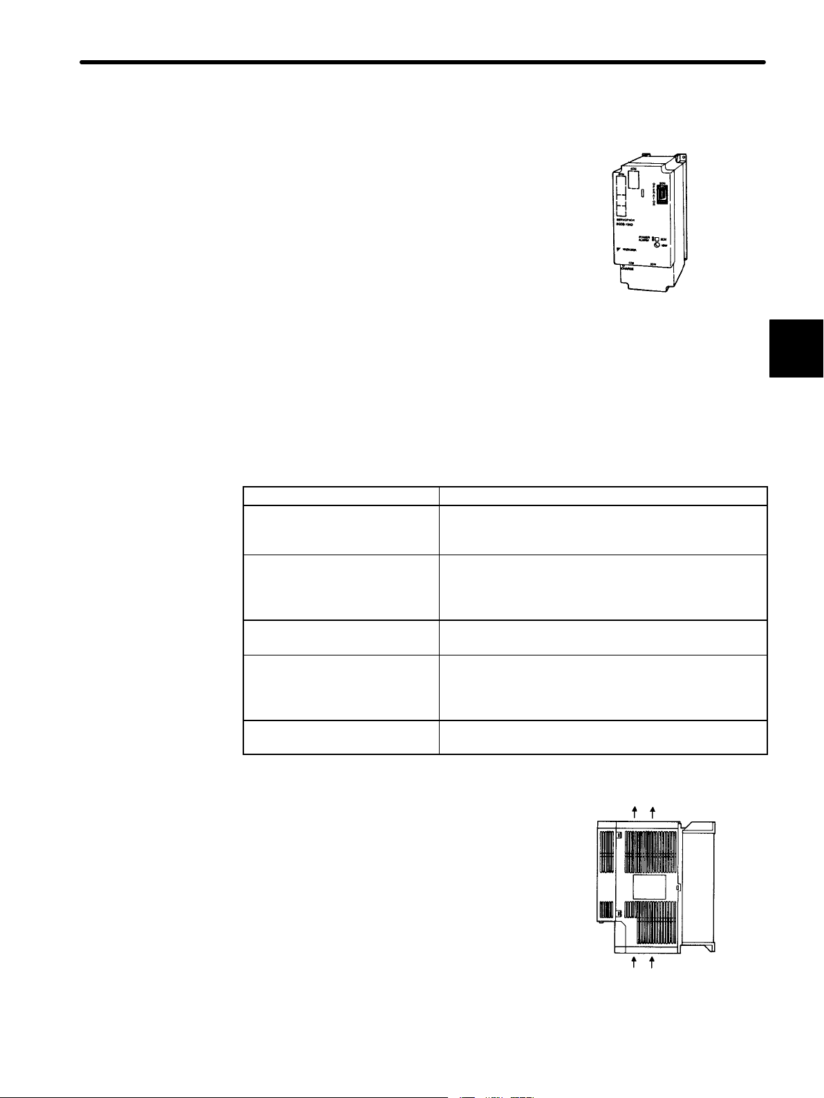
2.2.3 SERVOPACKs
2.2.3 SERVOPACKs
J External Appearance and Nameplate Examples
SERVOPACK model
2
Σ-Series SGDB
SERVOPACK
J Model Numbers
Σ-Series
SGDB SERVOPACK
Motor capacity
(See the following table.)
Voltage
A: 200 V
Model
D: torque, speed, position control
Applicable motor series
G: SGMG (1500 min−1)
M: SGMG (1000 min−1)
S: SGMS
D: SGMD
P: SGMP
Blank: SGM
Serial number
Applicable power supply
SGDB − 10 A D S −
Output
power
j
22
Option specifications
P: Duct ventilation type
Page 35

Motor Capacity (kW)
2.2 Installation
Maximum Applicable
Servomotor Capacity
Symbol
03
05
07
10
15
20
30
Capacity Maximum Applicable
Servomotor Capacity
Symbol
0.3
0.50
0.7
1.0
1.5
2.0
3.0
44
50
60
75
1A
1E
−
Capacity
4.4
5.0
6.0
7.5
11
15
−
2
23
Page 36

BASIC USES OF Σ-SERIES PRODUCTS
2.2.4 Installing the Servomotor
2.2.4 Installing the Servomotor
Servomotor SGMj type can be installed either horizontally or vertically. However, if the servomotor is installed incorrectly or in an inappropriate location, the service life will be shortened or unexpected problems will occur. To prevent this, always observe the installation
instructions described below.
When using the models with an oil seal, installing the motor with the output shaft up may
cause oil to enter the motor depending on the operating conditions. Check the operating
conditions.
2
NOTE
Before installation
Anticorrosive paint is coated on the edge of the motor shaft to prevent it from rusting during storage. Clean off the anticorrosive paint thoroughly using a cloth before installing the
motor.
Avoid getting thinner on other parts of the servomotor when cleaning the shaft.
Storage:
When the servomotor is to be stored with the power cable disconnected, store it in the
following temperature range:
:
Anticorrosive paint is
coated here
24
Between −20°C and 60°C
Page 37

Installation sites:
The servomotor SGMj type is designed for indoor use.
Install servomotor in an environment which meets the following conditions:
a) Free from corrosive and explosive gases
b) Well-ventilated and free from dust and moisture
c) Ambient temperature of 0 to 40°C
d) Relative humidity of 20% to 80% (non-condensing)
e) Inspection and cleaning can be performed easily
2.2 Installation
If the servomotor is used in a location subject to water or oil mist, the motor can be protected by taking necessary precautions on the motor side. However, if the shaft opening
is to be sealed, specify the motor with oil seal. Install with the electrical connector facing
downward.
Alignment
:
Align the shaft of the servomotor with that of the equipment to be controlled, then connect
the shafts with couplings. Install the servomotor so that alignment accuracy falls within
the range shown below.
Measure this distance at four different positions in the circumference. The
difference between the maximum and minimum measurements must be
0.03 mm or less. (Turn together with couplings)
Measure this distance at four different positions in the
circumference. The difference between the maximum and minimum
measurements must be 0.03 mm or less. (Turn together with
couplings)
2
NOTE
TERMS
If the shafts are not aligned properly, vibration will occur, resulting in damage to the bearings.
When using a pinion gear mounted directly to the motor output shaft, contact your YASKAWA
representative.
Shaft opening
Shaft
opening
Refers to the space where the shaft comes out from the motor.
25
Page 38

BASIC USES OF Σ-SERIES PRODUCTS
()
(
)
()
()
(
)
()
()
()
()
2.2.4 Installing the Servomotor cont.
A precision detector (encoder) is mounted on the opposite-drive end of the servomotor.
To mount a coupling, always protect the shaft from impacts that could damage the detector.
2
Perform a mechanical design so that
thrust load and radial load
motor shaft end falls within the range given in the following table.
Allowable
Motor Type
SGMG-05AjA
-09AjA
-13AjA
-20AjA
-30AjA
-44AjA
-55AjA
-75AjA
-1AAjA
-1EAjA
SGMG-03AjB
-06AjB
-09AjB
-12AjB
-20AjB
-30AjB
-44AjB
-60AjB
SGMS-10A 686 (154) 196 (44)
-15A 686 (154) 196 (44)
-20A 686 (154) 196 (44)
-30A 980 (221) 392 (88)
-40A 1176 (265) 392 (88)
-50A 1176 (265) 392 (88)
SGMD-22A 1176 (265) 490 (110)
-32A 1176 (265) 490 (110)
-40A 1176 (265) 490 (110) 65 (2.56)
SGMP-15A 490 (110) 147 (33) 35 (1.38)
Radial Load
Fr [N(lb)]
490 (110) 98 (22)
490 (110) 98 (22)
686 (154) 343 (77)
1176 (265) 490 (110)
1470 (331) 490 (110)
1470 (331) 490 (110)
1764 (397) 588 (132)
1764 (397) 588 (132)
1764 (397) 588 (132) 116 (4.57)
4998 (1125) 2156 (485) 116 (4.57)
490 (110) 98 (22)
490 (110) 98 (22)
686 (154) 343 (77)
1176 (265) 490 (110)
1470 (331) 490 (110)
1470 (331) 490 (110)
1764 (397) 588 (132)
1764 (397) 588 (132)
Allowable
Thrust
Load Fs
[N(lb)]
LR
[mm(in.)]
58 (2.28)
79 (3.11)
113 (4.45)
58 (2.28)
79 (3.11)
113 (4.45)
45 (1.77)
63 (2.48)
55 (2.17)
applied to the servo-
Reference Drawing
26
TERMS
Note Allowable radial loads shown above are the maximum values that could be ap-
plied to the shaft end.
Thrust load and radial load
2.
1. Thrust load: Shaft-end load applied parallel to the
centerline of a shaft
2. Radial load: Shaft-end load applied perpendicular to
the centerline of a shaft
Motor
Shaft end
1.
Page 39
2.2.5 Installing the SERVOPACK
Σ-Series SGDB SERVOPACK is a base-mount type
servo controller.
Incorrect installation will cause problems. Always observe the installation instructions described below.
Storage:
2.2 Installation
When the SERVOPACK is to be stored with the
power cable disconnected, store it in the following
temperature range:
Between −20°C and 85°C
Installation sites:
Situation Notes on Installation
Design the control panel size, unit layout, and cooling
When installed in a control panel
When installed near a heating
unit
When installed near a source of
vibration
When installed in a place
receiving corrosive gases
Others
method so that the temperature around the periphery of
the SERVOPACK does not exceed 55°C.
Suppress radiation heat from the heating unit and a
temperature rise caused by convection so that the
temperature around the periphery of the SERVOPACK
does not exceed 55°C.
Install a vibration isolator underneath the SERVOPACK
to prevent it from receiving vibration.
Corrosive gases do not immediately affect the
SERVOPACK but will eventually cause contactor-related
devices to malfunction. Take appropriate action to
prevent corrosive gases.
Avoid installation in a hot and humid place or where
excessive dust or iron powder is present in the air.
SGDB SERVOPACK
2
Orientation:
Install the SERVOPACK perpendicular to the wall
as shown in the figure.
The SERVOPACK must be orientated as shown
in the figure.
• Firmly secure the SERVOPACK through four
mounting holes.
Ventilation
27
Page 40

BASIC USES OF Σ-SERIES PRODUCTS
2.2.5 Installing the SERVOPACK cont.
Installation method:
When installing multiple SERVOPACKs side by side in a control panel, observe the following installation method:
2
Fan
Fan
30 mm or more 10 mm or more
Fan
50 mm or more
50 mm or more
a) Install SERVOPACK perpendicular to the wall so that the front panel (digital operator
mounted face) faces outward.
b) Provide sufficient space around each SERVOPACK to allow cooling by fan and natu-
ral convection.
c) When installing SERVOPACKs side by side, provide at least 10 mm space between
them and at least 50 mm space above and below them as shown in the figure above.
Install cooling fans above the SERVOPACKsto prevent the temperature around each
SERVOPACK from increasing excessively and also to maintain the temperature inside the control panel evenly.
28
d) Maintain the following conditions inside the control panel:
• Ambient temperature for SERVOPACK: 0 to 55°C
• Humidity: 90%RH or less
• Vibration: 4.9 m/s
2
• Condensation and freezing: None
• Ambient temperature to ensure long-term reliability: 45°C or less
Page 41

Power loss
Power loss of SERVOPACK is given below:
Power loss for rated output
2.2 Installation
SERVOPACK
type
SGDB-03ADj
SGDB-05ADj
SGDB-07ADj
SGDB-10ADj
SGDB-15ADj
SGDB-20ADj
SGDB-30ADj
SGDB-44ADj
SGDB-50ADj
SGDB-60ADj
SGDB-75ADj
SGDB-1AADj
SGDB-1EADj
Note a) Power loss of regenerative resistor is allowable loss. If the loss exceeds the
Output
current
(RMS value)
A
3.0 18
3.8 27 77
5.7 41 91
7.6 55 105
11.6 80 130
18.5 120 170
24.8 170 22 222
32.9 250
28.2 260 344
46.9 290
54.7 330
58.6 360
78.0 490 520
Power loss
in main
circui
W
t
Power loss
of
regenerative
resistor W
30 20
60 24
-
Power loss
in control
circuit
W
27
30
Power loss
in total
W
68
334
317
357
390
allowable loss, the regenerative resistor inside the SERVOPACK should be
removed and connected externally. Because the model in which the regenerative resistor is externally connected falls into non-standard specification categories, contact YASKAWA for further information.
For this non-standard type, “Y8” is appended to the end of the standard model
number.
2
b) For SGDB-60AD to 1EADj models, the regenerative resistor is placed sepa-
rately. The regenerative resistor unit provided from YASKAWA is described in
Section 3.8.4 Using Regenerative Resistor Units. Its power loss for
SGDB-60ADj is 180W (type: JUSP-RA04), and for SGDB-75ADj and
-1EADj is 350W(type: JUSP-RA05).
29
Page 42

2
BASIC USES OF Σ-SERIES PRODUCTS
2.3.1 Connecting to Peripheral Devices
2.3 Connection and Wiring
This section describes how to connect Σ-Series products to peripheral devices and explains a
typical example of wiring the main circuit. It also describes an example of connecting to main
host controllers.
2.3.1 Connecting to Peripheral Devices
This section shows a standard example of connecting Σ-Series products to peripheral devices and briefly explains how to connect to each peripheral device.
30
Page 43

Connector terminal block conversion unit
1CN connector kit
Cable with 1CN connector and
one end without connector
2.3 Connection and Wiring
Host controller
SERVOPACK is compatible with most P.L.C.
motion controllers and indexers.
See next page
Molded-case circuit
breaker (MCCB)
Used to protect
power supply
line. Shuts the
circuit off if
overcurrent is
detected.
Noise filter
Used to eliminate external
noise from power supply
line.
Types:
LF-350
LF-315
LF-320
LF-380K
Magnetic contactor
Turns the servo
ON or OFF.
Use a surge
suppressor for
the magnetic
contactor.
Molded-case
circuit breaker
Noise filter
Magnetic
contactor
Power supply
3 phase 200 VAC
MP920
Digital Operator
Allows the user to set parameters or operation
references and display operation status or
alarm status. The following two types are
available in addition to personal computers:
Mount type (JUSP-OP03A)
This type can be mounted
directly on the SERVOPACK.
Hand-held type
(JUSP-OP02A-1)
1-meter(3.3ft.)
cable included
Personal computer
Connecting cable type:
DE9405258
2
Brake power supply
Types:
LPSE-2H01 (for 200 V input)
LPDE-1H01 (for 100 V input)
Used for
servomotor
with brake.
Brake
power supply
Regenerative resistor unit
If the capacity of the regenerative resistor
is insufficient, remove the internal resistor
(P-B terminals) and connect it to the P-B
terminals).
For SERVOPACK with capacity more
than 6kW, a regenerative resistor unit is
mounted separately (connected to P1-B
terminals)
Magnetic
contactor
Power
ground
Cable for PG
Connector for
PG
See next page
Regenera-
tive resistor
(option)
31
Page 44
BASIC USES OF Σ-SERIES PRODUCTS
L
h
L
h
2.3.1 Connecting to Peripheral Devices cont.
• Connector terminal block conversion unit (Type: JUSP-TA50P)
The terminal block allows connection to a host controller.
• Cable with 1CN connector and one end without connector
1m (3.3ft) DE9406969-1
1CN
0.5 meter cable with
1CN connector
2
2m (6.6ft) DE9406969-2
1CN
3m (9.8ft) DE9406969-3
• 1CN connector kit (Type: DE9406970)
1CN
• Cable for PG
This cable is used to connect the encoder of servomotor to the SERVOPACK.
The following three types of cables are available according to encoder types.
For models SGMG, SGMS,
SGMD
a) Cable with a single connector (without connector on encoder side)
engt
3m (9.8ft) DE9406971-1 DE9406972-1
5m (16.4ft) DE9406971-2 DE9406972-2
10m (32.8ft) DE9406971-3 DE9406972-3
15m (49.2ft) DE9406971-4 DE9406972-4
20m (65.6ft) DE9406971-5 DE9406972-5
Incremental Absolute
Cable type
b) Cable with connectors on both side (straight plug on encoder side)
engt
3m (9.8ft) DE9407234-1 DE9407236-1
5m (16.4ft) DE9407234-2 DE9407236-2
10m (32.8ft) DE9407234-3 DE9407236-3
15m (49.2ft) DE9407234-4 DE9407236-4
20m (65.6ft) DE9407234-5 DE9407236-5
Incremental Absolute
Cable type
32
Page 45

2.3 Connection and Wiring
L
h
L
h
L
h
L
h
c) Cable with connectors on both side (L-shape plug on encoder side)
engt
3m (9.8ft) DE9407235-1 DE9407237-1
5m (16.4ft) DE9407235-2 DE9407237-2
10m (32.8ft) DE9407235-3 DE9407237-3
15m (49.2ft) DE9407235-4 DE9407237-4
20m (65.6ft) DE9407235-5 DE9407237-5
Incremental Absolute
Cable type
For models SGM, SGMP
a) Cable with connectors on both side
engt
3m (9.8ft) DP9320089-1 DP9320088-1
5m (16.4ft) DP9320089-2 DP9320088-2
10m (32.8ft) DP9320089-3 DP9320088-3
15m (49.2ft) DP9320089-4 DP9320088-4
20m (65.6ft) DP9320089-5 DP9320088-5
Incremental Absolute
Cable type
2
b) Cable with a single connector (without connector on SERVOPACK)
engt
3m (9.8ft) DP9320086-1 DP9320085-1
5m (16.4ft) DP9320086-2 DP9320085-2
10m (32.8ft) DP9320086-3 DP9320085-3
15m (49.2ft) DP9320086-4 DP9320085-4
20m (65.6ft) DP9320086-5 DP9320085-5
Incremental Absolute
Cable type
c) Cable without connectors
engt
3m (9.8ft) DP9400064-1 DP8409123-1
5m (16.4ft) DP9400064-2 DP8409123-2
10m (32.8ft) DP9400064-3 DP8409123-3
15m (49.2ft) DP9400064-4 DP8409123-4
20m (65.6ft) DP9400064-5 DP8409123-5
Incremental Absolute
Cable type
• Connector kit (DE9406973)for PG.
Connector on SERVOPACK side only
SERVOPACK
side
2CN
33
Page 46

BASIC USES OF Σ-SERIES PRODUCTS
2.3.2 Main Circuit Wiring and Power ON Sequence
2.3.2 Main Circuit Wiring and Power ON Sequence
The following diagram shows a typical example of wiring the main circuit for Σ-Series
products:
2
Three-phase 200 to 230 VAC (50/60 Hz)
+ 10%
–15%
Main circuit
power
Main circuit power
1MCCB: Circuit breaker (for inverter type)
FIL: Noise filter
1MC: Contactor
1Ry: Relay
1PL: Lamp for display
1SUP: Surge suppressor
1D: Flywheel diode
SERVOPACK
SGDB-jjADj
(Alarm lamp)
The following table shows the name and description of each main circuit terminal:
Terminal
Symbol
R, S, T
U, V, W
r, t
×2
P, B
P1, B
N
Note
P1 terminal is not available for SERVOPACK with power capacity less than 5 kW.
Name Description
Main power input
terminals
Motor connection
terminal
Control power
input terminals
Three-phase 200 to 230 VAC , 50/60Hz
Used to connect motor
Single phase 200 to 230 VAC , 50/60Hz
+ 10
–15
+ 10
–15
%
%
Ground terminal Connected to earth. (For power ground and motor ground).
Regenerative
resistor unit
connection
Normally, external connection is not required.
terminal
Regenerative
resistor unit
connection
Terminal used to connect regenerative resistor for
SERVOPACK with power capacity more than 6 kW.
terminal
Main circuit minus
side terminal.
Normally, external connection is not required.
34
Page 47

NOTE
2.3 Connection and Wiring
Form a power ON sequence as follows:
• Form a power ON sequence so that the power is turned OFF when a servo alarm signal
is output. (See the circuit diagram shown on the previous page.)
• Hold down the power ON push-button for at least two seconds. The SERVOPACK outputs a servo alarm signal for approximately two seconds or less when the power is
turned ON. This operation is required to initialize the SERVOPACK.
Power supply
2
Servo alarm (ALM) output signal
• Do not wire power lines and signal lines in the same duct or bundle them together.
Wire such that signal lines are kept apart from power lines by at least 30 cm.
• Twisted pair wire and multi-core twisted pair shielding wires should be used for signal
lines, encoder (PG) feedback line.
The length for wiring is 3 m maximum for the reference input line, 20 m maximum for the
PG feedback line.
• Do not touch the power terminal even if power was turned OFF.
High voltage may still remain in SERVOPACK.
Perform inspection only after the CHARGE lamp is OFF.
• Avoid frequently turning the power ON and OFF. Since the SERVOPACK has a capacitor in the power supply, a high charging current flows (for 0.2 second) when the power is
turned ON. Therefore, frequently turning the power ON and OFF causes the main circuit devices (such as capacitors and fuses) to deteriorate, resulting in unexpected
problems.
35
Page 48

BASIC USES OF Σ-SERIES PRODUCTS
2.3.3 Connection to Host Controller
2.3.3 Connection to Host Controller
The SGDB SERVOPACK can be connected to the following host controllers. For details,
refer to the technical documentation for the host controller.
• MP920
• GL-Series Positioning Module B2833
• GL-Series Positioning Module B2813
2
Speed/Torque
• OMRON Position Control Unit
• MITSUBISHI Positioning Unit
The following diagrams show connection examples with the host controllers manufactured by OMRON and MITSUBISHI.
J Connection to OMRON Position Control Unit C500-NC222
SERVOPACK for Speed/Torque Control
SERVOPACK
SGDB-jjADj
I/O Power Supply
C500-NC222
(Made by OMRON)
X-axis (Y-axis)
(ON when
positioning is
stopped)
(ON when
proximity is
detected)
36
/S-ON
(T-REF)
X-/A
X-/B
X-/C
* These signals are output for approximately two seconds when the power is turned
ON. Take this into consideration when designing a power ON sequence. Relay 1Ry is
used to stop main circuit power supply to SERVOPACK.
/PAO
/PBO
/PCO
Note The signals shown here are applicable only to OMRON Sequencer
C500-NC222 and Yaskawa SERVOPACK SGDB-VVADV.
Page 49

J
Connection to OMRON Position Control Unit C500-NC112
SERVOPACK for Position Control
2.3 Connection and Wiring
Position
C500-NC112
(Made by OMRON)
CW limit
CCW limit
Emergency stop
External interrupt
Home position
Home position
proximity
Local
Ready
Pulse output
CW + CCW
Direction output
CW
I/O
Power
Supply
(ON when proximity
is detected)
SERVOPACK
SGDB-jjADj *
/S-ON
/PCO
2
External
power
supply
+24V
*1 These signals are output for approximately two seconds when the power is turned ON. Take this
into consideration when designing a power ON sequence. Relay 1Ry is used to stop main circuit
power supply to SERVOPACK.
*2 Change the Cn-02 setting as follows:
Bit No. 3 = 1
Bit No. 4 = 0
Bit No. 5 = 0
*3 Manufactured by Yaskawa Controls Co., Ltd.
Note The signals shown here are applicable only to OMRON Sequencer C500-NC112 and
Yaskawa SERVOPACK SGDB-VVADV.
2
37
Page 50

2
BASIC USES OF Σ-SERIES PRODUCTS
2.3.3 Connection to Host Controllercont.
J
Connection to MITSUBISHI Positioning Unit AD72
SERVOPACK for Speed/Torque Control
Speed/Torque
AD72
(Made by MITSUBISHI)
Speed
reference
I/O power supply
(ON when
positioning
is stopped)
(ON when
proximity
is detected)
SERVOPACK
SGDB-jjADj
/S-ON
/PBO
/PAO
/PCO
*1 These signals are output for approximately two seconds when the power is turned ON. Take this into
consideration when designing a power ON sequence. Relay 1Ry is used to stop main circuit power
supply to SERVOPACK.
*2 These pin numbers are the same for both X and Y axes.
Note The signals shown here are applicable only to MITSUBISHI Sequencer AD72 and Yas-
kawa SERVOPACK SGDB-VVADV.
38
Page 51

Position
J
Connection to MITSUBISHI Positioning Unit AD75
SERVOPACK for Position Control
I/O power supply
+
−
READY
STOP
DOG
PGO
+24v
X axis (Y axis)
26
7
14
11
24
25
AD75
(Made by MITSUBISHI)
1Ry
+24v
0
24
ON when
positioning
is stopped
ON when
proximity
is detected
2.3 Connection and Wiring
SERVOPACK
SGDB-jjADj
L1C
L2C
L1
L2
L3
V
CN1
19
PCO
20
/PCO
/S-ON
P-OT
N-OT
U
V
W
47
40
42
43
CN2
CN1
Servomotor
A (1)
B (2)
C (3)
D (4)
M
PG
+24v
0
24
2
V
*
31
ALM+
32
ALM−
7
PULSE
8
/PULSE
11
SIGN
12
/SIGN
15
CLR
14
/CLR
PULSE
SIGN
CLEAR
1Ry
3
21
4
22
2.2KΩ
5
2
3
* These signals are output for approximately two seconds when the power is turned ON. Take this into
consideration when designing a power ON sequence. Relay 1Ry is used to stop main circuit power
supply to SERVOPACK.
Note The signals shown here are applicable only to MITSUBISHI Sequencer AD72 (B Type)
and Yaskawa SERVOPACK SGDB-VVADV.
39
Page 52

BASIC USES OF Σ-SERIES PRODUCTS
2.4.1 Test Run in Two Steps
2.4 Conducting a Test Run
This section describes how to conduct a full test run. The test run is divided into two steps.
Complete a test run in step 1 first, then proceed to step 2.
2.4.1 Test Run in Two Steps
Conduct the test run when wiring is complete.
2
Generally, conducting a test run for servo drives can be difficult. However, by following the two
steps described below, the test run can be performed safely and correctly.
NOTE To prevent accidents, initially conduct a test run only for a servomotor under no load (i.e., with
all couplings and belts disconnected). Do not run the servomotor while it is connected to a
machine.
The test run is divided here into steps 1 and 2.
Complete the test run in step 1 first, then proceed to step 2. The purposes of each step are
described on the next page.
40
Page 53

Step 1:
Conducting a test run for the motor without load Check that the motor is wired correctly....
Operate the motor with a Digital
Operator.
2.4 Conducting a Test Run
Conduct a test run with the motor shaft disconnected
from the machine.
Purpose:
• To check power supply circuit wiring
• To check motor wiring
• To check I/O signal (1CN) wiring
Outline:
Check wiring.
Do not connect
to a machine.
Step 2: Conducting a test run with the motor and
machine connected Adjust SERVOPACK according to ma-.................................
Connect to the machine and conduct a test run.
Purpose:
Speed adjustment by
autotuning
SGDB
SGM
Connect to the machine.
Outline:
• Turn the power ON
• Operate the motor with a digital op-
erator
• Check I/O signals (1CN)
• Conduct a test run using I/O signals
2
chine characteristics.
• To perform autotuning to adjust the motor according to machine characteristics
• To match the speed and direction of
rotation with the machinespecifications
• To check the final control mode
• Perform autotuning
• Adjust parameter settings
• Record parameter settings
End of test run
For servomotors with a brake, refer to Section 2.4.4 Supplementary Information on Test
Run before starting a test run.
The following pages describe the test run procedure in detail.
41
Page 54

2
BASIC USES OF Σ-SERIES PRODUCTS
2.4.2 Step 1: Conducting a Test Run for Motor without Load
2.4.2 Step 1: Conducting a Test Run for Motor without Load
Check that the motor is wired correctly.
If the motor fails to rotate properly during a servo drive test run, the cause most frequently lies
with incorrect wiring.
Conduct a test run for the motor without load according to the procedure described below.
For customers who use a servomotor with brake, refer to Section 2.4.4 Supplementary In-
formation on Test Run before starting a test run.
Operate the motor with
a Digital Operator.
Check wiring.
J Securing the Servomotor
Secure the servomotor to mounting holes to prevent
it from moving during operation. Alternatively, install
the servomotor on the machine and disconect couplings and belts.
J Verifying the Wiring
Disconnect connector 1CN, then check the motor
wiring in the power supply circuit.
I/O signals (1CN) are not to be used so leave connector 1CN disconnected.
J Turning the Power ON
Turn the SERVOPACK power ON. If the SERVOPACK is turned ON normally, the LED on the Digital
Operator lights up as shown in the figure.
Power is not supplied to the servomotor because the
servo is OFF.
If an alarm display appears on the LED as shown in
the figure above, the power supply circuit, motor wiring or encoder wiring is incorrect. In this case, turn
the power OFF, then correct the problem. For details, refer to Appendix D List of Alarm Displays.
Do not connect
to the machine.
Secure servomotor to mounting holes.
Do not connect
anything to the
motor shaft
(no-load
status).
Disconnect
connector
1CN
Normal display
Alternately displayed
Example of alarm display
Refer to Appen-
dix D List of
Alarm Displays.
42
Page 55

2.4 Conducting a Test Run
J Using the Digital Operator
Operate the motor with the Digital Operator. Check
that the motor runs normally.
Refer to Section 4.2.2 Operation Using the Digital
Operator.
J Connecting Signal Lines
Connect connector 1CN as follows:
1. Turn the power OFF.
2. Connect connector 1CN.
3. Turn the power ON again.
J Checking Input Signals.
Check the input signal wiring in monitor mode.
For the checking method, refer to Section
4.1.7 Operation in Monitor Mode.
Operation by Digital Operator
If an alarm occurs, the power supply
circuit, motor wiring, or encoder
wiring is incorrect.
Connect
connector
1CN.
2
Internal status bit display
(Un-05, Un-06)
Example of
Un-05
• Checking method
Turn each connected signal line ON and
OFF to check that the monitor bit display
changes accordingly.
Input Signal ON/OFF Monitor Bit Display
High level or open OFF Extinguished
0 V level ON Lit
The memory switch can be
eliminate the need
used to
for
external short-circuits in
wiring (see pages 56 and
131).
If the signal lines below are not wired correctly, the motor fails to rotate. Always wire
them correctly. (If signal lines are not to be used, short them as necessary.)
P-OT 1CN-42 Motor can rotate in forward direction when this input signal is at 0 V.
N-OT 1CN-43 Motor can reverse when this input signal is at 0 V.
S-ON 1CN-40 Servo is turned ON when this input signal is at 0 V. However, leave
the servo in OFF status.
43
Page 56

BASIC USES OF Σ-SERIES PRODUCTS
2.4.2 Step 1: Conducting a Test Run for Motor without Load cont.
2
J Turning Servo (Motor) ON
Turn the servo ON as follows:
S-ON
SERVOPACK
(1CN-40)
Servomotor
1. Check that no reference has been input.
Turn the servo ON.
For speed/torque control:
V-REF (1CN-5) and T-REF (1CN-9) are at 0 V.
For position control:
PULS (1CN-7) and SIGN (1CN11) are fixed to L level.
Note The parameter Cn-2B is used to set control modes (refer to Section 3.2 Setting
Parameters According to Host Controller).
2. Turn the servo ON signal ON.
Display when servo is turned ON
Set /S-ON (1CN-40) to 0 V. If normal, the motor
starts and the Digital Operator displays the
data as shown in the figure. If an alarm display
appears, take appropriate action as described
in Appendix D List of Alarm Displays.
Speed/Torque
J Operating by Reference Input
The operating procedure varies according to the setting of parameter ’Control mode
selection (Cn-2B)’.
SERVOPACK for Speed/Torque
This section describes the standard speed control
setting.
1. Gradually increase the speed reference input
(V-REF, 1CN-5) voltage. The motor will rotate.
When a host controller such as a programmable controller performs position control,
it may be difficult to directly input the speed reference voltage. In this case, constant
voltage reference should be input once to ensure correct operation.
2. Check the following items in monitor mode (see page 191):
SERVOPACK
(1CN-5)
(1CN-6)
Servomotor rotates at a speed
proportional to the reference voltage.
Servomotor
44
S Has a reference speed been input?
S Is the rotation speed the same value as the setting one?
Page 57

S Does the reference speed match the actual motor speed?
S Does the motor stop when no reference is input?
2.4 Conducting a Test Run
Position
Un-00
Actual motor speed
Un-01 Reference speed
3. If the motor rotates at an extremely slow speed when 0 V is specified as the reference
voltage, correct the reference offset value as described in Section 4.2.4 Reference
Offset Automatic Adjustment
4. To change motor speed or the direction of rotation, reset the parameters shown be
low.
Cn-03
Speed reference gain (see page 68)
Cn-02 bit 0 Reverse rotation mode (see page 54)
SERVOPACK for Position Control
1. Set parameter Cn-02 so that the reference pulse form matches the host controller out-
put form. (See page 183 for details on how to set parameters.)
Selecting reference pulse form (See page 70)
Bit 3
Cn-02
Bit 4
Bit 5
2
2. Input slow speed pulses from the host con-
troller and execute low-speed operation.
3. Check the following items in monitor mode
(see page 191):
Host
controller
Reference
pulse
SERVOPACK
/PULS
/SIGN
(1CN-7)
(1CN-8)
(1CN-11)
(1CN-12)
Servomotor
S Has a reference pulse been input?
S Is the motor speed as designed?
S Does the reference speed match the actual motor speed?
S Does the motor stop when no reference is input?
Un-00
Actual motor speed
Un-07 Reference pulse speed display
Un-08 Position error
4. To change motor speed or the direction of rotation, reset the parameters shown as
follows.
45
Page 58

2
BASIC USES OF Σ-SERIES PRODUCTS
2.4.3 Step 2: Conducting a Test Run with the Motor Connected to the Machine
Cn-24,Cn-25 Electronic gear ratio (see page 81)
Cn-02 bit 0 Reverse rotation mode (see page 54)
If an alarm occurs or the motor fails to rotate during the above operation, connector 1CN
wiring is incorrect or the parameter settings do not match the host controller specifications.
In this case, check the wiring and review the parameter settings, then repeat step 1.
Refer to Appendix D List of Alarm Displays and Appendix C List of Parameters.
This is all that is required to complete step 1 (conducting a test run for motor without load).
Whenever possible, perform tuning associated with the host controller and other necessary adjustments in step 1 (before installing the motor on the machine).
2.4.3 Step 2: Conducting a Test Run with the Motor Connected to the Machine
After step 1 is complete, proceed to step 2 in which a test run is conducted with the motor
connected to the machine. The purpose of step 2 is to adjust the SERVOPACK according to
the machine characteristics.
Conduct a test run according to the procedure described below.
SGDB
SERVOPACK
Purposes:
Servomotor
Connect to the machine.
S Autotuning
S Speed adjustment
NOTE Before proceeding to step 2, repeat step 1 (conducting a test run for the motor without load)
until you are fully satisfied that the test has been completed successfully. Operation faults that
arise after the motor is connected to the machine not only damage the machine but may also
cause an accident resulting in injury or death. Therefore, all items including parameters setting and wiring should be tested as conclusively as possible before step 1 is complete.
1. Check that power is OFF.
Turn the SERVOPACK power OFF.
Power
supply
SERVOPACK
46
Power
Page 59

2.4 Conducting a Test Run
2. Connect the servomotor to the machine.
Refer to Section 2.2.4 Installing the Servo-
motor.
3. Perform autotuning.
Tune the SERVOPACK according to the machine characteristics. Refer to Section 4.2.3
Autotuning.
4. Operate by reference input.
As in step 1 (conducting a test run for motor
without load), perform (8) Operate by refer-
ence input on page 44. Perform tuning
associated with the host controller.
Install servomotor on machine.
Servomotor
Autotuning:
Automatically measures
machine characteristics and
performs optimum tuning
SGDB
SERVOPACK Servomotor
Host
controller
Reference
SERVOPACK
2
Servomotor
5. Set parameters and record the settings.
Set parameters as necessary. Record all the
parameter settings for maintenance purposes.
This is all that is required to conduct the test run.
Normally, the machine may cause much friction because of an insufficient running-in period. After a test run is complete, perform adequate running-in.
2.4.4 Supplementary Information on Test Run
In the following cases, always refer to the information described below before starting a
test run:
• When using a servomotor with a brake
• When performing position control from the host controller
SERVOPACK
Parameters
Record the settings
J When Using a Servomotor with Brake
The brake prevents the motor shaft from rotating due to a backdriving torque. Such a
torque may be created by an external force or the force of gravity acting on the load and
may result in undesired motion or the load, should motor power be lost.
47
Page 60
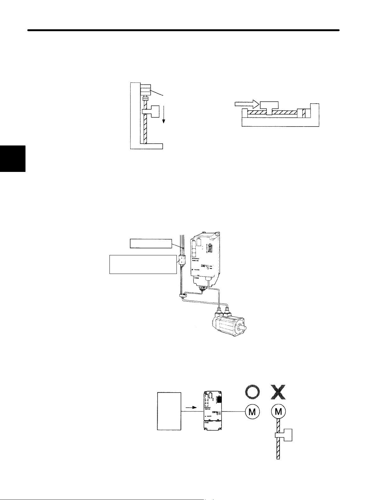
BASIC USES OF Σ-SERIES PRODUCTS
2.4.4 Supplementary Information on Test Run cont.
SERVOPACK uses the brake interlock output (BK) signal to control holding brake operation for a servomotor with brake.
2
• Vertical axis
Servomotor
Holding brake
Prevents the
motor from
rotating due to
gravity
• Axis to which external force is applied
External force
Servomotor
NOTE To prevent faulty operation caused by gravity (or external force), first check that the motor
and holding brake operate normally with the motor disconnected from the machine.
Then, connect the motor to the machine and conduct a test run.
For wiring of a servomotor with a brake, refer to Section 3.4.4 Using Holding Brake.
Power supply:
Three-phase
200 V
Brake control relay
SERVOPACK
Brake power supply
LPSE-2H01 (200 V input)
LPDE-1H01 (100 V input)
Servomotor with brake
J When Performing Position Control from the Host Controller
Check motor operation first and then conduct a test run as described in the table below.
SGDB-jjADj
Speed
reference
Host
controller
Test run
Position
control
Speed
control
for motor
without
load
48
Page 61

2.4 Conducting a Test Run
NOTE Check the motor operation with the motor disconnected from the machine. If the host con-
troller does not perform position control correctly, the motor may run out of control.
Reference from
Host Controller
Jogging
(constant-speed
reference input from
host controller)
Simple positioning
Overtravel (when
P-OT and N-OT
signals are used)
Check Items Check Method Review Items
Check the motor
speed as follows:
D Use the speed
monitor (Un-00) of
the digital operator.
Check whether the
speed reference gain
value (parameter
Cn-03) is correct.
Check whether the
dividing ratio count
(parameter Cn-0A) is
correct.
If the motor does not
stop, review the
P-OT and N-OT
wiring.
Motor speed
Number of motor
revolutions
Whether the motor
stops rotating when
P-OT and N-OT
signals are input
D Run the motor at
low speed. For
example, input a
speed reference of
−1
60 min
check that the
motor makes one
revolution per one
second.
D Input a reference
equivalent to one
motor revolution
and visually check
that the motor shaft
makes one
revolution.
D Check that the
motor stops when
P-OT and N-OT
signals are input
during continuous
motor operation.
and
2
2.4.5 Minimum Parameters Required and Input Signals
This section describes the minimum parameters and input signals that must be set to
conduct a test run.
For details on how to set each parameter, refer to Section 4.1.6 Operation in Parameter
Setting Mode.
J Parameters
• Basic parameters (common to speed, torque, position control)
Cn-11
Cn-01, bit E Encoder selection
Cn-2A Motor selection (check only in substance).
Cn-2C PG power supply voltage change
• For speed/torque control
Cn-03
Speed reference gain (see page 68)
Cn-0A Dividing ratio setting
Number of encoder pulses
49
Page 62

BASIC USES OF Σ-SERIES PRODUCTS
2.4.5 Minimum Parameters Required and Input Signals cont.
• For position control
2
Cn-02 bits 3, 4 and 5
Reference pulse form selection (see page 70)
Cn-24 Electronic gear ratio (numerator) (see page 81)
Cn-25 Electronic gear ratio (denominator) (see page 81)
When these parameters (except for Cn-03) are changed, always turn the power OFF,
then back ON. This makes the new setting valid.
If the specified direction of rotation differs from the actual direction of rotation, the wiring
may be incorrect. In this case, recheck the wiring and correct it accordingly. Then, if the
direction of rotation is to be reversed, set the following parameter:
Cn-02 (bit 0)
Reverse rotation mode (see page 54)
After changing the Cn-02 setting, always turn the power OFF, then ON, to make the new
setting valid.
J Input Signals
The following table lists the minimum input signals required to conduct a test run. For details of each input signal, refer to the relevant page.
Signal Name
/S-ON (servo ON) 1CN-40
(forward
P-OT
N-OT
rotation
prohibited)
(reverse
rotation
prohibited)
Pin
Number
1CN-42
1CN-43
Function
Switching between motor ON and OFF status. The
memory switch can be used to eliminate the need for
external short-circuit wiring (see page 131).
Overtravel limit switch
The memory switch can be used to eliminate the
need for external short-circuit wiring (see page 56).
50
Page 63

APPLICATIONS OF Σ-SERIES
PRODUCTS
This chapter is prepared for readers whowish to learn more about the applications ofΣ-series products after fully understanding Chapter 2 Basic Uses of
-series Products. It explains how to set parameters for each purpose and
Σ
how to use each function. Read the applicable sections according to your requirements.
3.1 Setting Parameters According to Machine
3.2 Setting Parameters According to Host
3
3
Characteristics 54..........................
3.1.1 Changing the Direction of Motor Rotation 54...............
3.1.2 Setting the Overtravel Limit Function 56..................
3.1.3 Restricting Torque 59.................................
Controller 64..............................
3.2.1 Inputting Speed Reference 64...........................
3.2.2 Inputting Position Reference 68.........................
3.2.3 Using Encoder Outputs 73..............................
3.2.4 Using Contact I/O Signals 77...........................
3.2.5 Using Electronic Gear 79..............................
3.2.6 Using Contact Input Speed Control 83....................
3.2.7 Using Torque Control 87...............................
3.2.8 Using Torque Feed-forward Function 94..................
3.2.9 Using Torque Restriction by Analog Voltage Reference 95....
3.2.10 Using the Reference Pulse Inhibit Function (INHIBIT) 97.....
3.2.11 Using the Reference Pulse Input Filter Selection Function 98..
3.2.12 Using the Analog Monitor 99...........................
3.3 Setting Up the Σ SERVOPACK 100............
3.3.1 Setting Parameters 100.................................
3.3.2 Setting the Jog Speed 101...............................
3.3.3 Setting the Number of Encoder Pulses 102..................
3.3.4 Setting the Motor Type 103..............................
3.3.5 Adjusting the Encoder Supply Voltage 104..................
51
Page 64

3
Chapter Table of Contents, Continued
3.4 Setting Stop Mode 105.......................
3.4.1 Adjusting Offset 105...................................
3.4.2 Using Dynamic Brake 106..............................
3.4.3 Using Zero-Clamp 107.................................
3.4.4 Using Holding Brake 108...............................
3.5 Running the Motor Smoothly 113..............
3.5.1 Using the Soft Start Function 113.........................
3.5.2 Using the Smoothing Function 114........................
3.5.3 Adjusting Gain 114....................................
3.5.4 Adjusting Offset 115...................................
3.5.5 Setting the Torque Reference Filter Time Constant 115........
3.6 Minimizing Positioning Time 117..............
3.6.1 Using Autotuning Function 117..........................
3.6.2 Setting Servo Gain 117.................................
3.6.3 Using Feed-forward Control 119..........................
3.6.4 Using Proportional Control 119..........................
3.6.5 Setting Speed Bias 120.................................
3.6.6 Using Mode Switch 121................................
3.7 Forming a Protective Sequence 127............
3.7.1 Using Servo Alarm Output and Alarm Code Output 127.......
3.7.2 Using Servo ON Input Signal 130.........................
3.7.3 Using Positioning Complete Signal 131....................
3.7.4 Using Speed Coincidence Output Signal 134................
3.7.5 Using Running Output Signal 136........................
3.7.6 Using OL Warning and Alarm Output Signals 138............
3.7.7 Using Servo Ready Output Signal 140.....................
3.7.8 Handling of Power Loss 141.............................
3.8 Special Wiring 142..........................
3.8.1 Wiring Instructions 142.................................
3.8.2 Wiring for Noise Control 144............................
3.8.3 Using More Than One Servo Drive 149....................
3.8.4 Using Regenerative Resistor Units 151.....................
3.8.5 Using an Absolute Encoder 152..........................
3.8.6 Extending an Encoder Cable 162.........................
3.8.7 Using SGDB SERVOPACK with High Voltage Line 164.......
3.8.8 Connector Terminal Layouts 166.........................
52
Page 65

Before Reading this Chapter
This chapter describes how to use each 1CN connector I/O signal for the SGDB SERVOPACK and how to set the corresponding parameter.
Refer to corresponding section described below as necessary.
• A list of I/O signals of 1CN connector : Appendix B List of I/O Signals
• Terminal arrangement for I/O signals of 1CN connector : Section 3.8.8 Connector Terminal
Layouts
• A list of parameters : Appendix C List of Parameters
• How to set parameters : Section 4.1.6 Operation in Parameter Setting Mode
Parameters are divided into the following two types.
Memory switch
Cn-01 and Cn-02
Constant setting
Cn-03 and later
Set each bit to ON or OFF to select a function.
Set a numerical value such as a torque limit
value or speed loop gain.
3
53
Page 66

APPLICATIONS OF Σ-SERIES PRODUCTS
3.1.1 Changing the Direction of Motor Rotation
3.1 Setting Parameters According to Machine Characteristics
This section describes how to set parameters according to the dimensions and performance
of the machine to be used.
3.1.1 Changing the Direction of Motor Rotation
This SERVOPACK provides a reverse rotation mode in which the direction of rotation can
be reversed without altering the servomotor wiring. With the standard setting, forward
rotation is defined as counterclockwise (ccw) rotation viewed from the drive end.
3
If reverse rotation mode is used, the direction of motor rotation can be reversed without
other items being changed. The direction (+/−) of axial motion is reversed.
Standard Setting Reverse Rotation Mode
Forward Run Reference
Reverse Run Reference
Encoder output
from SERVOPACK
PAO (Phase A)
PBO (Phase B)
Encoder output
from SERVOPACK
PAO (Phase A)
PBO (Phase B)
Encoder output
from SERVOPACK
PAO (Phase A)
PBO (Phase B)
Encoder output
from SERVOPACK
PAO (Phase A)
PBO (Phase B)
54
Page 67
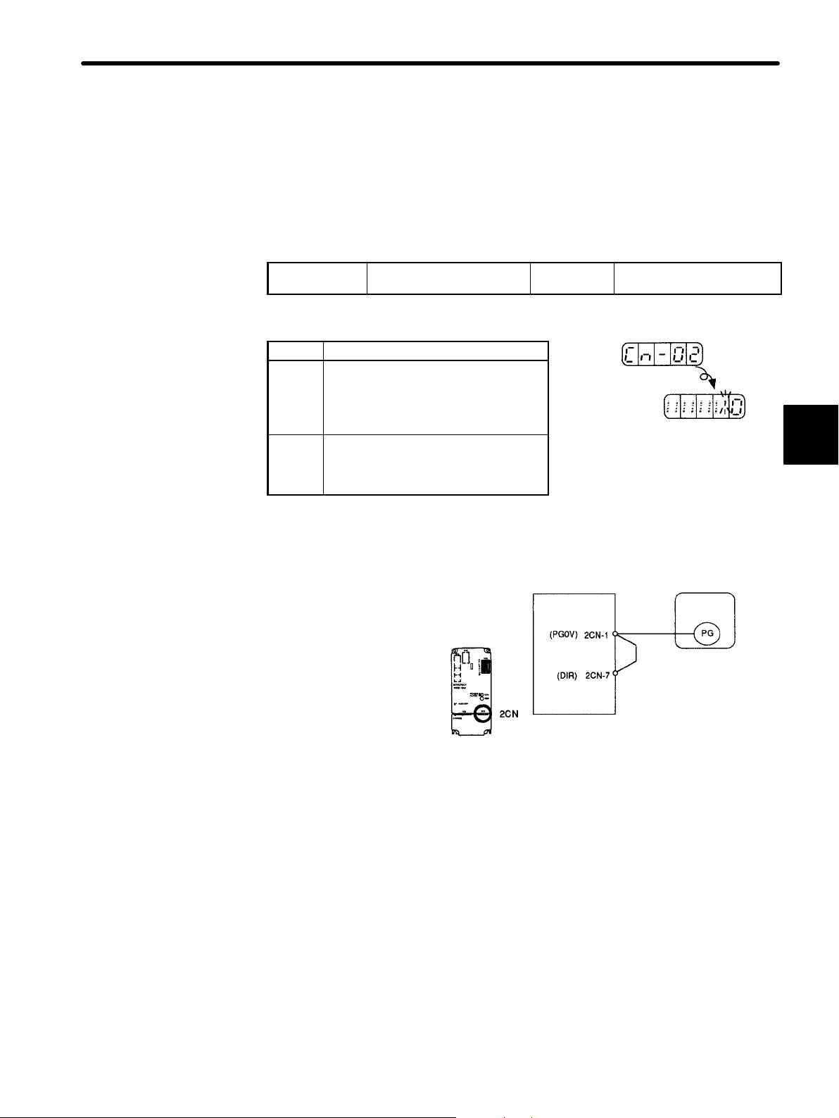
3.1 Setting Parameters According to Machine Characteristics
J Setting Reverse Rotation Mode
Reverse rotation mode can be set in either of the following two ways. Normally, method 1
is easier to use.
Method 1: Setting Memory Switch
Set bit 0 of memory switch Cn-02 to select reverse rotation mode.
Cn-02 Bit 0 Rotation Direction
Selection
Factory
Setting: 0
Set the direction of rotation.
Setting Meaning
Forward rotation is
defined as
0
counterclockwise
rotation when viewed
from the drive end.
Forward rotation is
defined as clockwise
1
rotation when viewed
from the drive end.
(Standard
setting)
(Reverse
rotation
mode)
Method 2: Shorting the Wiring in the 2CN Connector
Reverse rotation mode can be set for the 2CN
connector for the encoder. This method is used
to standardize parameter settings without using
the memory switch.
In this case, reverse rotation
mode is set regardless of the
memory switch setting.
SGDB
SERVOPACK
SGDB SERVOPACK
For Speed/Torque Control
and Position Control
3
SGMj servomotor
Encoder
Short 2CN-1 and 2CN-7 in
the 2CN connector.
55
Page 68

APPLICATIONS OF Σ-SERIES PRODUCTS
3.1.2 Setting the Overtravel Limit Function
3.1.2 Setting the Overtravel Limit Function
The overtravel limit function forces the moving part of the machine to stop when it exceeds the movable range.
J
Using the Overtravel Limit Function
To use the overtravel limit function, connect the following input signal terminals correctly.
3
Forward Rotation Prohibited
→ Input P-OT 1CN-42
→ Input N-OT 1CN-43
(Forward Overtravel)
Reverse Rotation Prohibited
(Reverse Overtravel)
Input terminals for overtravel limit switch.
For linear motion, connect a limit switch to prevent
damage to the machine.
P-OT
N-OT
ON: 1CN-42 is
at low level.
OFF: 1CN-42
is at high level.
ON: 1CN-43 is
at low level.
OFF: 1CN-43
is at high level.
Forward rotation allowed. Normal operation status.
Forward rotation prohibited (reverse rotation allowed).
Reverse rotation allowed. Normal operation status.
Reverse rotation prohibited (forward rotation allowed).
Reverse
rotation side
SGMj
servomotor
For Speed/Torque
Control and
Position Control
For Speed/Torque
Control and
Position Control
Forward
rotation side
Limit switch
SGDB
SERVOPACK
1CN-42
1CN-43
56
J
Specifying whether Input Signals for Overtravel are to be Used
Use the following parameters (memory switch) to specify whether input signals for overtravel are to be used.
Cn-01 Bit 2
Cn-01 Bit 3
Use of P-OT Input Signal Factory
Setting: 0
Use of N-OT Input Signal Factory
Setting: 0
Specifies whether the P-OT input signal for prohibiting forward rotation at overtravel (1CN-42) is
to be used and whether the N-OT input signal for
prohibiting reverse rotation at overtravel
For Speed/Torque Control
and Position Control
For Speed/Torque Control
and Position Control
SGDB SERVOPACK
1CN
-42
-43
(1CN-43) is to be used.
Specifies “1” when external short-circuit wiring is
to be omitted.
The short-circuit wiring shown in the
figure can be omitted when P-OT and
N-OT are not used.
Page 69

3.1 Setting Parameters According to Machine Characteristics
Bit Setting Meaning
Uses the P-OT input signal for prohibiting forward rotation. (Forward
0
rotation is allowed when 1CN-42 is at 0 V.)
Bit 2
Does not use the P-OT input signal for prohibiting forward rotation.
1
(Forward rotation is always allowed. This has the same effect as shorting
1CN-42 to 0 V.)
Uses the N-OT input signal for prohibiting reverse rotation. (Reverse
0
rotation is prohibited when 1CN-43 is open. Reverse rotation is allowed
Bit 3
when 1CN-43 is at 0 V.)
Does not use the N-OT input signal for prohibiting reverse rotation.
(Reverse rotation is always allowed. This has the same effect as shorting
1
1CN-43 to 0 V.)
J
Setting the Motor Stopping Method
If the P-OT and N-OT input signals are used, set the following parameters to specify how
to stop the motor.
Cn-01 Bit 8
Cn-01 Bit 9
How to Stop Motor at
Overtravel
Operation to be Performed
when Motor Stops after
Factory
Setting: 0
Factory
Setting: 0
Overtravel
•
Inputs signal for prohibiting forward rotation
(P-OT, 1CN-42)
•
Inputs signal for prohibiting reverse rotation
(N-OT, 1CN-43)
Specify how to stop the motor when either of the
above signals is input.
Setting Meaning
Stop the motor in the same way as when the servo is turned OFF.
0
Cn-01
bit 8
The motor is stopped by dynamic brake or coasts to a stop. Either of
these stop modes is selected by setting bit 6 of Cn-01.
Stop the motor by decelerating it with the preset torque.
1
Preset value: Cn-06 (EMGTRQ) emergency stop torque
Overtravel
0
0
Bit 6
1
Bit 8
1
Invalid for Torque Control
Invalid for Torque Control
Stop mode After stop
Stop by
dynamic brake
Coasting to a
stop
Deceleration
stop
Releasing
dynamic brake
Servo OFF
0
Bit 9
Zero-clamp
1
3
If deceleration stop mode is selected, specify the operation to be done after the motor
stops.
Setting Meaning
0
Cn-01
bit 9
Turns the servo OFF when the motor stops in deceleration stop mode.
Causes the motor to enter zero-clamp status after it stops in deceleration
1
stop mode.
In torque control mode, the motor stops in the same way as when the servo is turned OFF,
regardless of the bit 8 setting.
57
Page 70
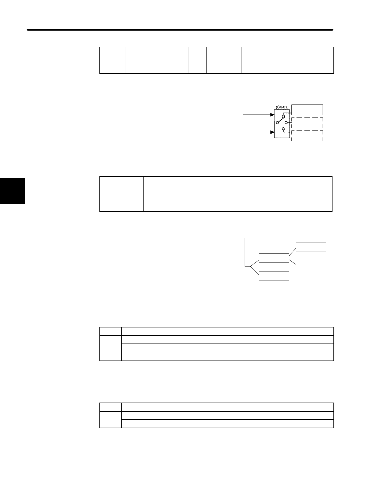
APPLICATIONS OF Σ-SERIES PRODUCTS
Cn-01
3.1.2 Setting the Overtravel Limit Function
3
Cn-06
EMGTRQ
Emergency Stop
Torque
Unit:%Setting
Range: 0 to
Maximum
Torque
Specifies the stop torque to be applied at overtravel when the input signal for prohibiting forward or
reverse rotation is to be used.
Specifies a torque value in terms of a percentage
of the rated torque.
Cn-01 Bit 6
Cn-01 Bit 7
How to Stop Motor at Servo
OFF
Operation to Be Performed
when Motor Stops after Servo
OFF
Factory
Setting: 0
Factory
Setting: 1
Factory
Setting:
Maximum
Torque
Input signal for
prohibiting
forward rotation
P-OT (1CN-42)
Input signal for
prohibiting reverse
rotation
N-OT (1CN-43)
Invalid for 2.0 kW or more
Valid when Cn-01 bit 8
=1
Memory
switch
Emergency
stop torque
Stop by
dynamic brake
Coasting to a
stop
The SERVOPACK enters servo OFF status when:
•
Servo ON input signal (/S-ON, 1CN-40) is
turned OFF.
•
Servo alarm arises.
•
Power is turned OFF.
Servo OFF
Stop mode
Stop by
dynamic brake
0
Bit 6
1
Coasting to a
stop
Dynamic brake is a function that
electrically applies brakes by using a
resistor to consume motor rotation
energy.
After stop
Releasing
dynamic brake
0
Bit 7
Holding
1
dynamic brake
Specify how to stop the motor when one of the
above events occurs during operation.
Setting Meaning
0
Cn-01
bit 6
Stops the motor by dynamic brake.
Causes the motor to coast to a stop.
1
The motor power is OFF and stops due to machine friction.
If dynamic brake stop mode is selected, specify the operation to be performed when the
motor stops.
Setting Meaning
0
Cn-01
bit 7
Releases dynamic brake after the motor stops.
Does not release dynamic brake even after the motor stops.
1
58
Note
For SERVOPACKs of 2.0 kW or more, bit 7 of Cn-01 can be set to 0 only.
Page 71

3.1.3 Restricting Torque
The SERVOPACK can provide the following torque control:
3.1 Setting Parameters According to Machine Characteristics
• Torque restriction Level 1: To restrict the maximum output torque to protect
• Torque control Level 3: To always control output torque, not speed
the machine or workpiece
Level 2: To restrict torque after the motor moves the
machine to a specified position
Level 4: To alternately use speed control and torque
control
This section describes how to use levels 1 and 2 of the torque restriction function.
J How to Set Level 1: Internal Torque Limit
The maximum torque is restricted to the values set in the following parameters.
Cn-08
Cn-09
TLMTF
Forward Rotation
Torque Limit
TLMTR
Reverse Rotation
Torque Limit
Setting
Unit:
Range: 0 to
%
800
Unit:%Setting
Range: 0 to
800
Factory
Setting:
800
Factory
Setting:
800
For Speed/Torque
Control and Position
Control
For Speed/Torque
Control and Position
Control
3
Sets the maximum torque values for
forward rotation and reverse rotation,
respectively.
Sets these parameters when torque
must be restricted according to machine conditions.
This torque restriction function always
monitors torque, and outputs the signal
shown on the right when the limit value
is reached.
Specifies a torque limit value in terms of
a percentage of the rated torque.
If a value higher than the maximum
torque is set, the maximum torque value is used.
Example of Use: Machine Protection
Torque limit
Motor speed
Output Signal for Torque Restriction Function
• /CLT
• Monitor mode (Un-06) bit 4
Parameter Setting:
(Cn-2D) = jj3, j3j,3jj
Note that too small a torque limit value will result in torque shortage at acceleration or deceleration.
Torque
59
Page 72

APPLICATIONS OF Σ-SERIES PRODUCTS
g
3.1.3 Restricting Torque
• Using /CLT Signal
This section describes how to use contact output signal /CLT as a torque limit output signal.
3
I/O power
supply
Photocoupler Output
Per output:
Maximum operation
voltage: 30 VDC
Maximum output
current: 50 mA DC
SGDB SERVOPACK
/CLT+
/CLT−
Torque Limit Output For Speed/Torque
Output → /CLT 1CN-*1
Control and
Position Control
This signal indicates whether motor output torque (current) is being restricted.
ON status: The circuit between 1CN-*1
and 1CN-*2 is closed.
1CN-*1 is at low level.
OFF status: The circuit between 1CN-*1
and 1CN-*2 is open.
1CN-*1 is at high level.
Motor output torque is being restricted.
(Internal torque reference is greater than the
preset value.)
Motor output torque is not being restricted.
(Internal torque reference is equal to or below
the preset value.)
Preset Value: Cn-08 (TLMTF)
Cn-09 (TLMTR)
Cn-18 (CLMIF) : P-CL input only
Cn-19 (CLMIR) : N-CL input only
Cn-2D
Output Signal Selection Factory
Setting: 210
For Speed/Torque Control
and Position Control
Specifies the terminal to which /CLT is to be output.
Setting
1s place = 3 25 26
10s place = 3 27 28
100s place = 3 29 30
Output terminals (1CN-)
*1 *2
/CLT
Torque
detection
1s place = 3
10s place = 3
100s place = 3
(1CN-25, 26)
(1CN-27, 28)
(1CN-29, 30)
60
Page 73
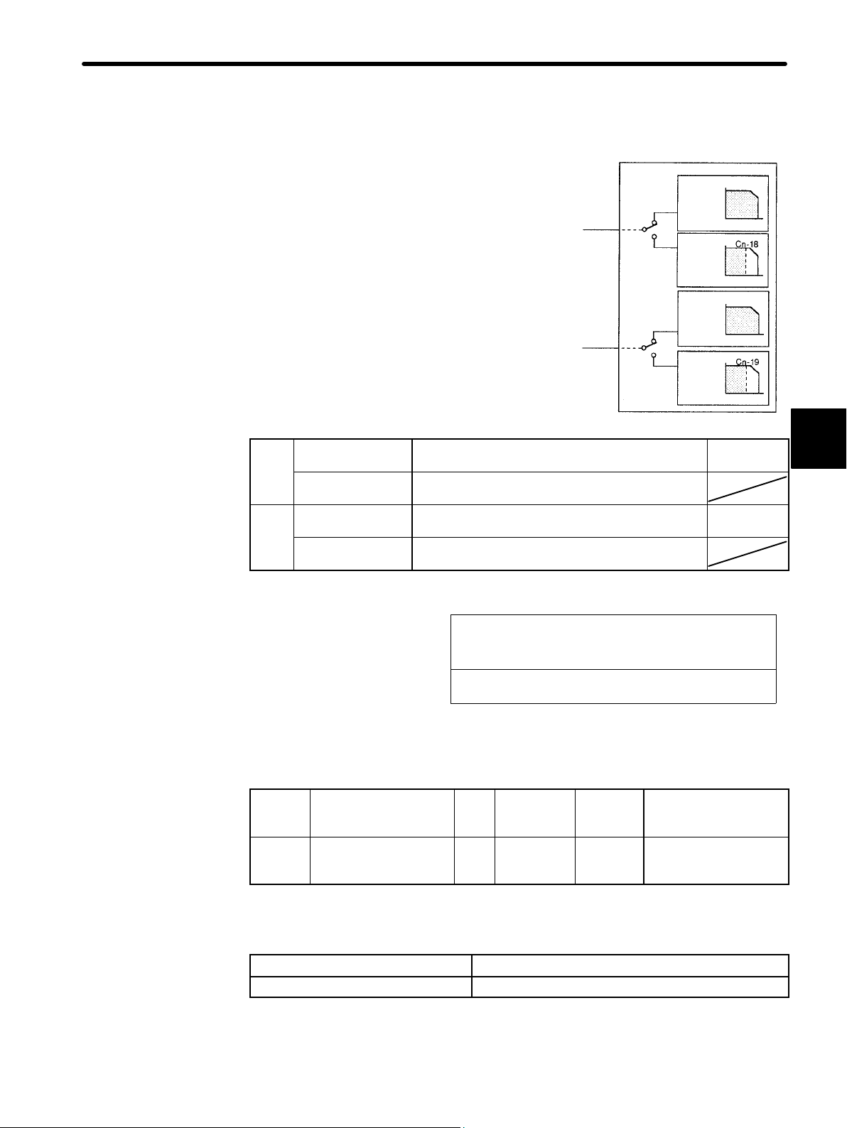
J How to Set Level 2: External Torque Limit
P-CL
3.1 Setting Parameters According to Machine Characteristics
First, use a contact input signal to make the torque
(current) limit value set in the parameter valid.
Torque limit can be set separately for forward and
reverse rotation.
To use this function, always set bit 2 of memory
switch Cn-02 to 0 (standard setting). The contact
input speed control function cannot be used.
N-CL
ON: 1CN-45 is at
low level.
OFF: 1CN-45 is at
high level.
ON: 1CN-46 is at
low level.
OFF: 1CN-46 is at
high level.
Torque restriction applies during forward rotation. Limit value:
Torque restriction does not apply during forward
rotation.
Torque restriction applies during reverse rotation. Limit value:
Torque restriction does not apply during reverse
rotation.
/P-CL
1CN-45
/N-CL
1CN-46
SGDB SERVOPACK
Forward
rotation
Reverse
rotation
Without
torque limit
With
torque limit
Without
torque limit
With
torque limit
Speed
Torque
Speed
Torque
Speed
Torque
Speed
Torque
3
Cn-18
Cn-19
Output Signal for Torque Restriction Function
/CLT
This torque restriction
function outputs the signal
shown on the right.
•
Status indication mode bit data
•
• Monitor mode Un-05 bit 4
Parameter Setting:
Cn-2D = jj3, j3j,3jj
Examples of Use:
• Forced stopping
• Holding workpiece by robot
Cn-18
Cn-19
CLMIF
Forward External
Torque Limit
CLMIR
Reverse External
Torque Limit
Unit:%Setting
Range: 0 to
800
Unit:%Setting
Range: 0 to
800
Factory
Setting:
100
Factory
Setting:
100
For Speed/Torque
Control and Position
Control
For Speed/Torque
Control and Position
Control
Sets a torque limit value when torque is restricted by external contact input.
This function is valid when Cn-2B is set to 0, 1, 2, 7, 8, 9, 10, 11.
When /P-CL (1CN-45) is input Applies torque restriction as specified in Cn-18
When /N-CL (1CN-46) is input Applies torque restriction as specified in Cn-19
For torque restriction by analog voltage reference, refer to
Restriction by Analog Voltage Reference
.
Section 3.2.9 Using Torque
61
Page 74

APPLICATIONS OF Σ-SERIES PRODUCTS
P-CL
3.1.3 Restricting Torque
• Using /P-CL and /N-CL Signals
This section describes how to use input signals /P-CL and /N-CL as torque limit input signals.
3
I/O power supply
Host controller
/P-CL
/N-CL
→ Input /P-CL 1CN-45
→ Input /N-CL 1CN-46
SGDB SERVOPACK
1CN-47
5mA
1CN-45
1CN-46
Forward External Torque Limit
Input (Speed Selection 1)
Reverse External Torque Limit
Input (Speed Selection 2)
These signals are for forward and reverse external torque (current) limit input.
This function is useful in forced stopping.
Photocoupler
For Speed/Torque
Control and
Position Control
For Speed/Torque
Control and
Position Control
Output Signal for Torque
Restriction Function
• /CLT
• Status indication mode bit data
• Monitor mode Un-05 bit 4
• Parameter Setting:
Cn-2D = jj3, j3j,3jj
62
N-CL
ON: 1CN-45 is at
low level.
OFF: 1CN-45 is at
high level.
ON: 1CN-46 is at
low level.
OFF: 1CN-46 is at
high level.
Torque restriction applies during forward rotation. Limit value:
Torque restriction does not apply during forward
rotation. Normal operation status.
Torque restriction applies during reverse rotation. Limit value:
Torque restriction does not apply during reverse
rotation. Normal operation status.
The signal shown on the above are output while torque is being restricted.
This function is changed to another function depending on the setting of memory
Note
switch Cn-2B (see below).
Cn-18
Cn-19
Page 75

3.1 Setting Parameters According to Machine Characteristics
To use /P-CL and /N-CL as torque limit input signals, set the following constant.
Cn-2B
Control Mode Selection Factory
Setting: 0
Prohibits the contact input speed control function.
If the contact input speed control function is used,
the contents of the input signals shown below will
change.
For Speed/Torque Control
and Position Control
SGDB SERVOPACK
Run the
motor at
internally
set speed
Contact
input
SGMj
servomotor
After this memory switch is reset, the meanings of the following signals will also
change:
Monitor mode (Un-05) bit 7 and bit 8
Setting Meaning Input Signal
Used to switch between P control and
PI control and to perform other
functions.
input
input
0, 1, 2,
7, 8, 9,
10, 11
Does not use
the contact
input speed
control
function.
/P-CON (1CN-41)
/P-CL (1CN-45) Used for forward external torque limit
/N-CL (1CN-46) Used for reverse external torque limit
3
3, 4, 5, 6
Uses the contact
input speed
control function.
0: OFF, 1: ON
/P-CON /P-CL /N-CL Speed Setting
Direction of
rotation
0: Forward
1: Reverse
00
01
11
10
0 reference and so on
Cn-1F (SPEED1)
Cn-20 (SPEED2)
Cn-21 (SPEED3)
63
Page 76
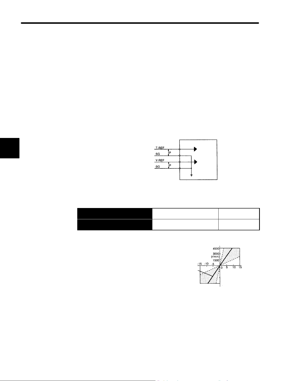
APPLICATIONS OF Σ-SERIES PRODUCTS
3.2.1 Inputting Speed Reference
3.2 Setting Parameters According to Host Controller
This section describes how to connect a Σ-series Servo to a host controller and how to set
parameters.
3.2.1 Inputting Speed Reference
Input a speed reference by using the following input signal “speed reference input.” Since
this signal can be used in different ways, set the optimum reference input for the system
to be created.
SGDB SERVOPACK
3
Torque reference input
(analog voltage input)
Speed reference input
(analog voltage input)
→ Input V-REF 1CN-5
→ Input SG 1CN-6
Speed Reference Input For Speed Control
Signal Ground for Speed
Reference Input
Use these signals when speed control (analog
reference) mode is selected (Cn-2B is set to 0, 4,
7, 9, or 10).
For ordinary speed control, always wire the VREF and SG terminals.
Motor speed is controlled in proportion to the input
voltage between V-REF and SG.
1CN-9
1CN-10
1CN-5
1CN-6
↕P: Represents twisted-pair cables
Standard
setting
Torque
reference
Speed
reference
Reference
speed
Only
For Speed Control
Only
−1500
−3000
−4500
Set the slope in
Cn-03 (VREFGN).
Input voltage (V)
64
J Standard Example:
Cn-03 = 500: This setting means that 6 V is 3000 min
Examples:
−1
+6 V input → 3000 min
+1 V input → 500 min
−3 V input → 1500 min
in forward direction
−1
in forward direction
−1
in reverse direction
Parameter Cn-03 can be used to change the voltage input range.
−1
Page 77

3.2 Setting Parameters According to Host Controller
0
J Example of Input Circuit
(See the figure on the right)
For noise control, always use twisted-pair
cables.
Recommended Variable Resistor for Speed Setting:
Type 25HP-10B manufactured by Sakae Tsushin Kogyo Co., Ltd.
When position control is performed by a host controller such as a programmable controller, connect V-REF and SG to speed reference output terminals on the host controller. In this case, adjust
Cn-03 according to output voltage specifications.
The internal ¦12 V power supply can be used.
+12V
−12V
Maximum output current: 30mA
Voltage: 12V¦2V
1CN-23
1CN-24
1/2 W or more
Host controller SERVOPACK
Speed
reference
output
terminals
Feedback
pulse input
terminals
↕P: Represents twisted-pair cables
470Ω 1/2W or more
SGDB SERVOPACK
1CN-5
1CN-6
SG
1CN-5
1CN-6
1CN-33
/PAO
1CN-34
1CN-35
/PBO
1CN-36
3
Set parameter Cn-2B to select one of the following control modes.
Cn-2B Control Mode Selection Factory
Setting: 0
Cn-2B
Setting
Control Method
Speed Control
This is normal speed control.
• Speed reference is input from V-REF (1CN-5).
• /P-CON (1CN-41) signal is used to switch
between P control and PI control.
1CN-41 is
PI control
open
1CN-41 is
P control
at 0 V
For Speed/Torque Control
and Position Control
Speed
reference
P/PI
changeover
SGDB SERVOPACK
1CN-5
/P-CON
1CN-41
65
Page 78

APPLICATIONS OF Σ-SERIES PRODUCTS
10
Zero clamp
is
performed
when
Condition1:/P-CON
i
d
Condition
2:
Motor
speed
p
preset
value
3.2.1 Inputting Speed Reference
3
Cn-2B
Setting
4
7, 9
Control Method
Speed Control (Contact Reference) $ Speed
Control (Analog Reference)
This speed control allows switching between
contact and analog references.
• Analog reference is input from V-REF (1CN-5).
• /P-CL (1CN-45) and /N-CL (1CN-46) are used
to switch between contact and analog
references.
• Contact input speed is selected.
1CN-45 1CN-46
Open Open Analog
reference
Closed Open
Closed Closed
Contact
reference
Open Closed
Position/Torque Control $ Speed Control
This control mode can be switched between
position/torque control and speed control.
• Speed reference is input from V-REF (1CN-5).
• /P-CON (1CN-41) is used to switch the control
mode between position/torque control and
speed control.
1CN-41 is
Position/Torque control
open
1CN-41 is
Speed control
at 0 V
Contact
input
speed control
reference
Speed
reference
Control method
changeover
SGDB SERVOPACK
Speed
reference
V-REF
/P-CL
/N-CL
SGDB SERVOPACK
/P-CON
1CN-5
1CN-45
1CN-46
1CN-5
1CN-41
Zero-clamp Speed Control
This speed control allows the zero-clamp function
to be set when the motor stops.
• Speed reference is input from V-REF (1CN-5).
• /P-CON (1CN-41) signal is used to turn the
zero-clamp function ON or OFF.
1CN-41 is
open
1CN-41 is
at 0 V
Turns zero-clamp function
OFF
Turns zero-clamp function
ON
SGDB SERVOPACK
Speed
reference
Zero-clamp
Zero-clampisperformed when
the following two conditions are
met:
Condition 2: Motor speed
Preset value: Cn-0F (ZCLVL)
1CN-5
/P-CON
1CN-41
ON.
drops below the
s turne
reset value.
.
66
Page 79

•
Using /P-CON Signal:
3.2 Setting Parameters According to Host Controller
Proportional Control, etc. For Speed Control
→ Input /P-CON 1CN-41
The function of input signal /P-CON changes with Cn-2B setting.
SGDB SERVOPACK
Switching between P control and PI control
/P-CON
Cn-2B
Cn-2B Setting Meaning of /P-CON Signal
0, 1
Switching between proportional (P) control and
proportional/integral (PI) control
2 (Not used)
3, 4, 5, 6
Changing the direction of rotation during contact input speed
control
7, 8, 9 Switching the control mode
10
11
Switching between zero-clamp enabled and zero-clamp
prohibited modes
Switching between INHIBIT enabled and INHIBIT prohibited
modes
Switching between zero-clamp enabled mode and
zero-clamp prohibited mode
Switching between INHIBIT enabled mode and INHIBIT
prohibited mode
Switching the control mode
Changing the direction of rotation
and Position
Control
3
TERMS
Adjust the speed reference gain using the following parameter.
Cn-03
VREFGN Speed
Reference Gain
Unit:
(
min
V
−1
)/
Setting
Range:
10 to
2000
For Speed Control
Only
Zero-clamp function
This function is used for a system in which the host controller does not form a position loop.
In this case, the stopping position may shift even if a speed reference is set to 0. If the zeroclamp function is turned ON, a position loop is internally formed so that the stopping position
is firmly “clamped.”
67
Page 80
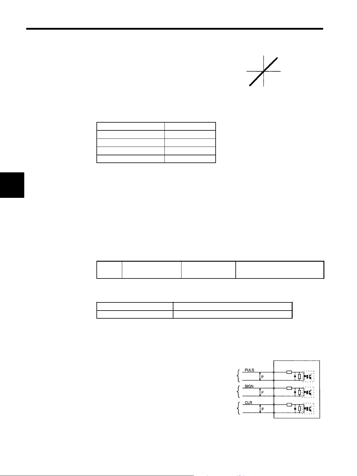
3
APPLICATIONS OF Σ-SERIES PRODUCTS
3.2.2 Inputting Position Reference
Sets the voltage range for speed reference input
V-REF (1CN-5). Sets this parameter according to
the output form of the host controller or external
circuit.
The factory setting is as follows:
Rated speed ¦1%/6V
Motor Series Factory Setting
SGMG (1500 min−1) 250
SGMG (1000 min−1) 167
SGMD 333
SGMS, SGM, SGMP 500
Reference
speed
−1
)
(min
Reference
voltage (V)
Set this slope.
3.2.2 Inputting Position Reference
Input a position reference by using the following input signal “reference pulse input.”
Since there are several specifications for input signal, select reference input for the system to be created.
To use position control, set the following constant.
Cn-2B
Control Mode
Selection
Note Speed / Torque Control is selected at factory setting.
Cn-2B Setting Control Mode
1 Position Control
J Move Reference by Pulse Input
Inputs a move reference by pulse
input.
Position reference can correspond
to the following three types of output form:
• Line driver output
• +12V Open collector output
Factory setting: 0 For Speed / Torque Control and
Position Control
Reference pulse
input
Reference sign
input
Error counter
clear input
↕P: Represents twisted-pair cables
/PULS
/SIGN
/CLR
SGDB SERVOPACK
Photocoupler
1CN-7
1CN-8
1CN-11
1CN-12
1CN-15
1CN-14
68
• +5V Open collector output
Page 81

Connection Example 1: Line Driver Output
3.2 Setting Parameters According to Host Controller
Line Driver Used:
SN75174 manufactured by
Host controller
Line driver
Texas Instruments Inc., or
MC3487 or equivalent.
Connection Example 2: Open Collector Output
Sets the value of limiting re-
Host controller
sistor R1 so that input current i falls within the following
range:
Input Current i: 7 to 15 mA
SGDB SERVOPACK
Photocoupler
SGDB SERVOPACK
/PULS
/SIGN
/CLR
1CN-7
1CN-8
1CN-11
1CN-12
1CN-15
1CN-14
3
i
/PULS
1CN-7
1CN-8
Photocoupler
Examples:
• When Vcc is 12 V,
R1 = 1 kΩ
• When Vcc is 5 V,
R1 = 180 Ω
↕P: Represents twisted-pair cables
Note The signal logic for open collector output is as follows.
When Tr1 is ON Equivalent to high level input
When Tr1 is OFF Equivalent to low level input
The power supply inside the
Host controller
SERVOPACK can be used.
About 9mA
If this power supply is used, it
will not be isolated from 0 V
in the SERVOPACK.
1.5 V or less
when ON
/SIGN
/CLR
/PULS
/SIGN
1CN-11
1CN-12
1CN-15
1CN-14
SGDB SERVOPACK
Photocoupler
/CLR
69
Page 82

APPLICATIONS OF Σ-SERIES PRODUCTS
Pul
M
d
R
M
pulse
0
pulse
)
3.2.2 Inputting Position Reference
J Selecting the Reference Pulse Form
Use the following memory switch to select the reference pulse form to be used:
3
→ Input PULS 1CN-7
→ Input /PULS 1CN-8
→ Input SIGN 1CN-11
→ Input /SIGN 1CN-12
Reference Pulse Input For Position Control Only
Reference Pulse Input For Position Control Only
Reference Sign Input For Position Control Only
Reference Sign Input For Position Control Only
The motor only rotates at an angle proportional to the input pulse.
Cn-02 Bit 3
Cn-02 Bit 4
Cn-02 Bit 5
Reference Pulse Form
Selection
Reference Pulse Form
Selection
Reference Pulse Form
Selection
Sets the form of a reference pulse that is external-
Factory
Setting: 0
Factory
Setting: 0
Factory
Setting: 0
For Position Control Only
For Position Control Only
For Position Control Only
Host
controller
ly output to the SERVOPACK.
Sets the pulse form according to the host controller specifications.
Position
reference
pulse
SGDB SERVOPACK
(1CN-7)
(1CN-11)
Set also the input pulse logic in bit D of Cn-02.
Bit D
(Positive
logic
setting
Cn-02
Bit5Bit4Bit
0 0 0
0 1 0
0 1 1
1 0 0
0 0 1
3
Input
Multipli-
er
¢1
¢2
¢4
se
Refer-
ence
Pulse
Form
Sign +
pulse
train
Twophase
train
with 90
phase
difference
CW
pulse +
CCW
pulse
°
otorForwar
Reference
(1CN-7)
(1CN-11)
(1CN-7)
(1CN-11)
(1CN-7)
(1CN-11)
un
otorReverseRun
Reference
(1CN-7)
(1CN-11)
(1CN-7)
(1CN-11)
(1CN-7)
(1CN-11)
70
Page 83

Bit D
1
pulse
ic
set
(1CN-1
1)
1
(Nega-
tive log-
ic set-
ting)
Cn-02
Bit
Bit
4
5
0 0 0
0 1 0
0 1 1
1 0 0
0 0 1
Bit
3
Input
Input
Pulse
Pulse
Multipli-
Multipli-
er
er
¢1
¢2
¢4
Refer-
Refer-
ence
ence
Pulse
Pulse
Form
Form
Sign +
pulse
train
Twophase
train
with 90°
phase
difference
CW
pulse +
CCW
pulse
3.2 Setting Parameters According to Host Controller
Motor Forward Run
Motor Forward Run
Reference
Reference
(1CN-7)
(1CN-11)
(1CN-7)
-
(1CN-7)
(1CN-11)
Motor Reverse Run
Motor Reverse Run
Reference
Reference
(1CN-7)
(1CN-11)
(1CN-7)
(1CN-11)
(1CN-7)
(1CN-11)
3
Servo ON
Base block
Sign +
pulse train
PG pulse
Input Pulse Multiply Function:
When the reference form is two-phase pulse train
with 90° phase difference, the input pulse multiply
function can be used.
The electronic gear function can also be used to
convert input pulses.
Example of I/O Signal Generation Timing
Release
1CN-11
1CN-7
Number of
motor move
pulses
(1CN-7)
(1CN-11)
x4
x2
x1
Input reference pulse
t1 ≤ 30 ms
t2 ≤ 6ms
(When parameter
Cn-12 is set to 0)
t3 ≥ 40 ms
t4, t5, t6 ≤ 2ms
t7 ≥ 20 μs
/COIN
t7
Note The interval from the time the servo ON signal is turned ON until a reference pulse is
input must be at least 40 ms. Otherwise, the reference pulse may not be input.
The error counter clear (CLR) signal must be ON for at least 20 μs. Otherwise, it becomes invalid.
71
Page 84
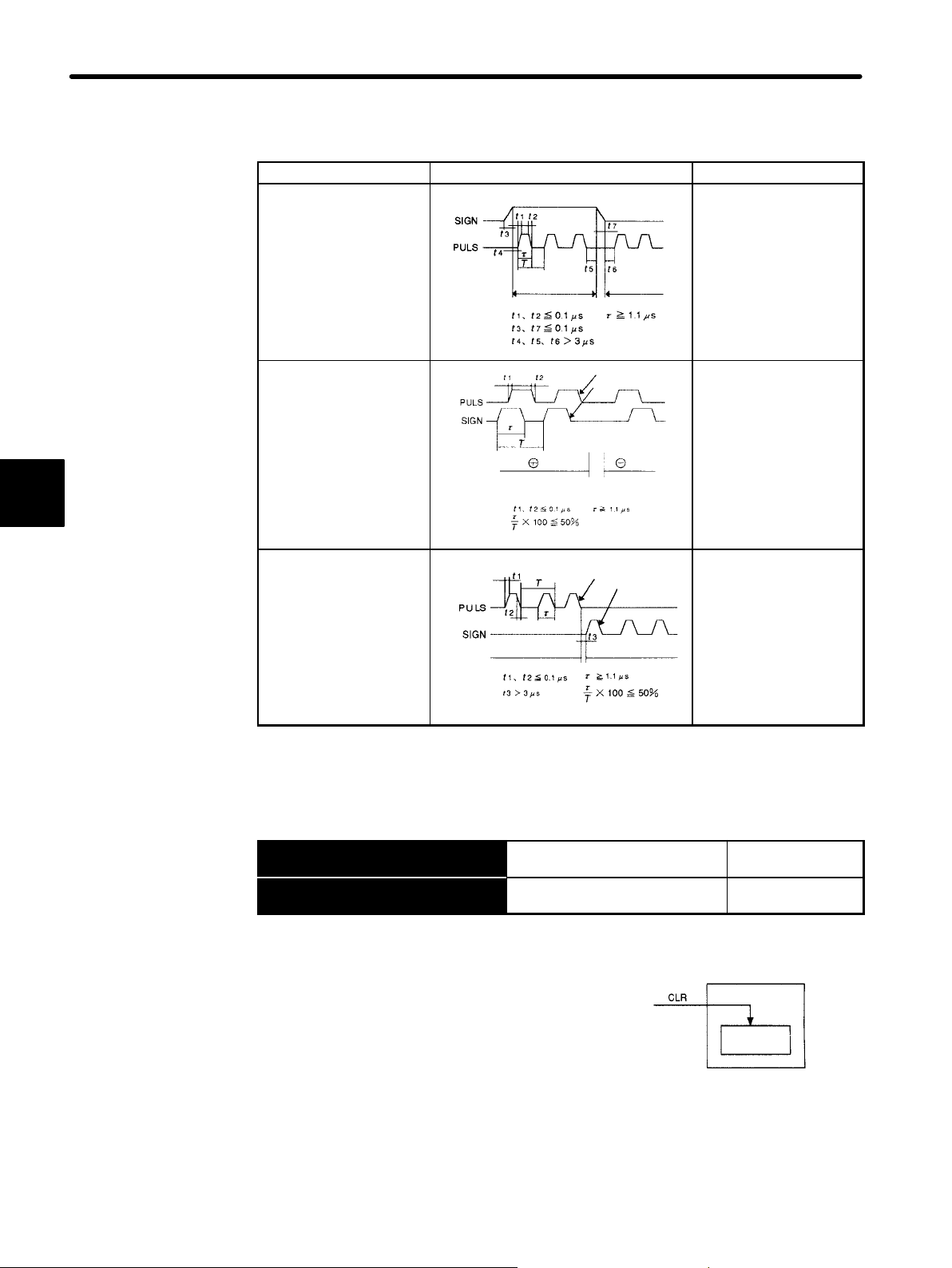
APPLICATIONS OF Σ-SERIES PRODUCTS
3.2.2 Inputting Position Reference
Allowable Voltage Level and Timing for Reference Pulse Input
Reference Pulse Form Electrical Specifications Remarks
Sign + pulse train input
(SIGN + PULS signal)
Maximum reference
frequency: 450 kpps
The signs for each
reference pulse are as
follows:
¨: High level
©: Low level
¨ reference © reference
3
90° different two-phase
pulse train
(phase A + phase B)
Maximum reference
frequency
x 1 multiplier:
450 kpps
x 2 multiplier:
Phase B is 90°
forward from phase B
400 kpps
x 4 multiplier:
200 kpps
CCW pulse + CW pulse
Maximum reference
frequency: 450 kpps
¨ reference © reference
J Cleaning the Error Counter
The following describes how to clear the error counter.
Phase A
Phase B
Phase B is 90°
behind phase B
CCW pulse
CW pulse
Parameter Cn-02 (bits 3,
4 and 5) is used to
switch the input pulse
multiplier mode.
72
→ Input CLR 1CN-15
→ Input /CLR 1CN-14
Setting the CLR signal to high level does the following:
• Sets the error counter inside the SERVOPACK
to 0.
• Prohibits position loop control.
Error Counter Clear Input For Position
Control Only
Error Counter Clear Input For Position
Control Only
SGDB SERVOPACK
Clear
Position loop
error counter
Use this signal to clear the error counter from the
host controller.
Bit A of memory switch Cn-02 can be set so that the error counter is cleared only once
when the leading edge of an input pulse rises.
Page 85

3.2 Setting Parameters According to Host Controller
Cn-02 Bit A
Error Counter Clear Signal
Selection
Selects the pulse form of error counter clear signal CLR (1CN-15).
Setting Meaning
Clears the error counter when the CLR
signal is set at high level. Error pulses
0
do not accumulate while the signal
remains at high level.
Clears the error counter only once when
the rising edge of the CLR signal rises.
1
3.2.3 Using Encoder Outputs
Encoder output signals divided inside the SERVOPACK can be output externally. These
signals can be used to form a position control loop in the host controller.
Factory
Setting: 0
For Position Control Only
1CN-15
1CN-15
Cleared state
Cleared only once at this point
3
SGMj
servomotor
encoder
Phase A
Phase B
Phase C
SGDB
SERVOPACK
Frequency
dividing
circuit
This output is
explained here.
Host
controller
Phase A
Phase B
Phase C
TERMS
Divided (or dividing)
“Dividing” means converting an input pulse train from the encoder mounted on the motor
according to the preset pulse density and outputting the converted pulse. The unit is pulses
per revolution.
73
Page 86

APPLICATIONS OF Σ-SERIES PRODUCTS
3.2.3 Using Encoder Outputs
The output circuit is for line driver output. Connect each signal line according to the following circuit diagram.
3
SGDB
SERVOPACK
Phase A
Phase B
Phase C
↕P: Represents twisted-pair cables
1CN-33
1CN-34
1CN-35
1CN-36
1CN-19
1CN-20
1CN-1
1CN-50
/PAO
/PBO
/PCO
Host controller
Line receiver
Phase A
Phase B
Phase C
Choke
coil
Smoothing
capacitor
Line receiver used: SN75175 manufactured by Texas
Instruments Inc. or MC3486 (or
equivalent)
R (termination resistor): 220 to 470 Ω
C (decoupling capacitor): 0.1 μF
J I/O Signals
I/O signals are described below.
Output → PAO 1CN-33
Output → /PAO 1CN-34
Output → PBO 1CN-35
Output → /PBO 1CN-36
Output → PCO 1CN-19
Output → /PCO 1CN-20
Encoder Output
Phase-A
Encoder Output
Phase-/A
Encoder Output
Phase-B
Encoder Output
Phase-/B
Encoder Output
Phase-C
Encoder Output
Phase-/C
For Speed/Torque Control
and Position Control
For Speed/Torque Control
and Position Control
For Speed/Torque Control
and Position Control
For Speed/Torque Control
and Position Control
For Speed/Torque Control
and Position Control
For Speed/Torque Control
and Position Control
Divided encoder signals are output.
Always connect these signal terminals when a position loop is formed in the host controller to perform position control.
Set a dividing ratio in the following parameter.
Dividing ratio setting Cn-0A PGRAT
74
The dividing ratio setting is not relevant to the gear ratio setting (Cn-24, 25) for the electronic gear function of the SERVOPACK when used for position control.
Page 87
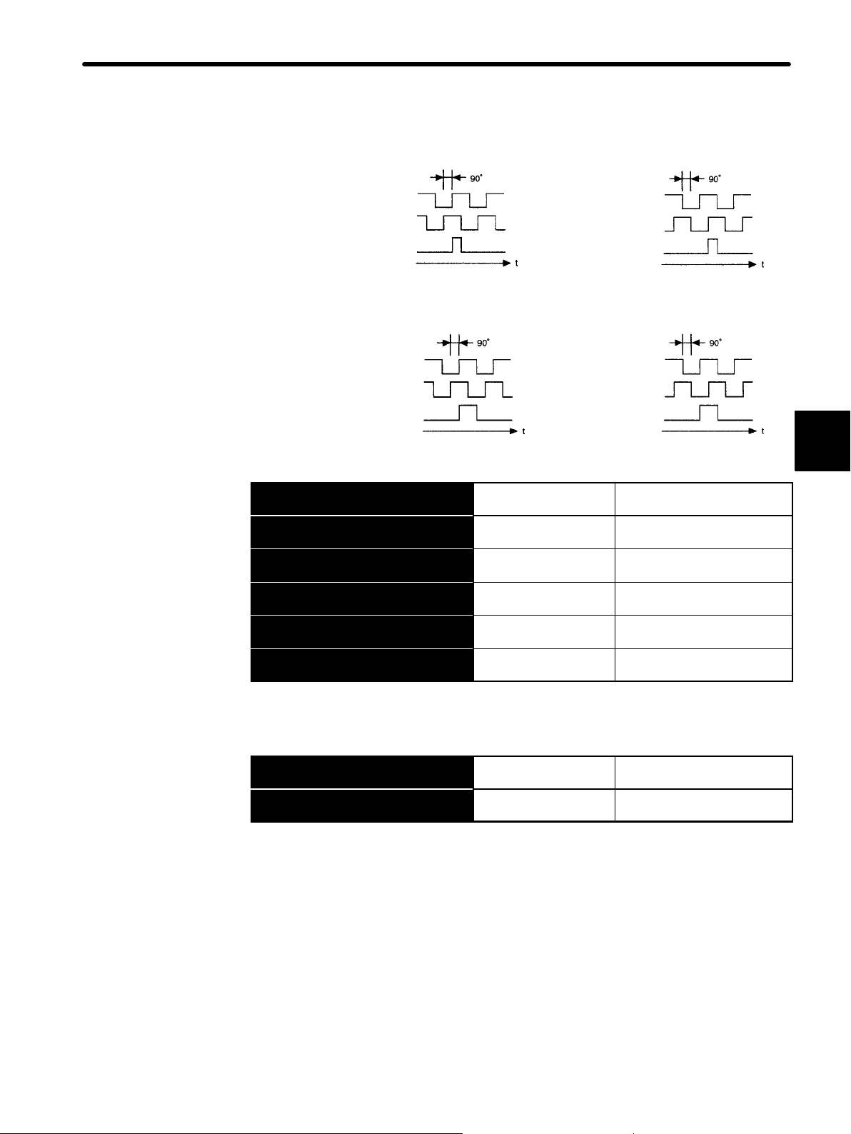
3.2 Setting Parameters According to Host Controller
Output Phase Form
Incremental Encoder
Forward rotation Reverse rotation
Phase A
Phase B
Phase A
Phase B
Phase C
Absolute Encoder
Forward rotation Reverse rotation
Phase A
Phase B
Phase C
→ Input SEN 1CN-4
→ Input SG 1CN-2
Output → PSO 1CN-48
Output → /PSO 1CN-49
→ Input BAT 1CN-21
→ Input BAT0 1CN-22
SEN Signal Input For Speed/Torque Control
Signal Ground For Speed/Torque Control
Encoder Output
Phase-S
Encoder Output
Phase-/S
Battery (+) For Speed/Torque Control
Battery (−) For Speed/Torque Control
Phase C
Phase A
Phase B
Phase C
3
Only
Only
For Speed/Torque Control
and Position Control
For Speed/Torque Control
and Position Control
and Position Control
and Position Control
Use these signals (SEN to BAT0) for absolute encoders. For details, refer to Section
3.8.5 Using an Absolute Encoder.
Output → SG 1CN-1
Output → FG 1CN-50
Signal Ground For Speed/Torque Control
and Position Control
Frame Ground For Speed/Torque Control
and Position Control
SG: Connect to 0 V on the host controller.
FG: Connect to the cable shielded wire.
75
Page 88

APPLICATIONS OF Σ-SERIES PRODUCTS
3.2.3 Using Encoder Outputs
J Selecting the Encoder Type
Use the following memory switch to specify the type of the encoder to be used.
3
Cn-01 Bit E
Encoder Type Selection Factory
Setting: 0
For Speed/Torque Control
and Position Control
Sets the encoder type according to the servomotor type as shown in the table.
After changing the memory switch setting, always turn the power OFF, then ON.
Motor Type
encoder
specifications
2 Incremental encoder:
3 Incremental encoder:
6 Incremental encoder:
W Absolute encoder:
S Absolute encoder:
Number of Encoder Pulses Per Revolution (P/R)
8192 pulses per revolution
2048 pulses per revolution
4096 pulses per revolution
1024 pulses per revolution
8192 pulses per revolution
J Setting the Pulse Dividing Ratio
Set the pulse dividing ratio in the following parameter.
Cn-0A
PGRAT
Dividing Ratio Setting
Unit:
P/R
Setting
Range: 16
to 32768
For Speed/Torque
Control and Position
Control
Setting
0
1
Sets the number of output pulses for PG output
signals (PAO, /PAO, PBO and /PBO).
Pulses from motor encoder (PG) are divided by
the preset number of pulses before being output.
SGMj
servomotor
encoder
Phase A
Phase B
SGDB
SERVOPACK
Frequency
dividing
Output terminals:
PAO (1CN-33)
/PAO (1CN-34)
PBO (1CN-35)
/PBO (1CN-36)
Phase A
Phase B output
The number of output pulses per revolution is set in this parameter. Set this value according to the reference unit of the machine or controller to be used.
The setting range varies according to the encoder used.
Setting example:
Motor Type
Number of Encoder Pulses Per Revolution Setting Range
encoder
specifications
2 Incremental encoder: 8192 pulses per revolution 16 to 8192
3 Incremental encoder: 2048 pulses per revolution 16 to 2048
6 Incremental encoder: 4096 pulses per revolution 16 to 4096
W Absolute encoder: 1024 pulses per revolution 16 to 1024
S Absolute encoder: 8192 pulses per revolution 16 to 8192
Preset value: 16
1 revolution
After changing the parameter setting, always turn the power OFF, then ON.
76
Page 89

3.2.4 Using Contact I/O Signals
J Contact Input Signal Terminal Connections
These signals are used to control SGDB SERVOPACK operation. Connect these signal
terminals as necessary.
I/O power
supply
Host controller
3.2 Setting Parameters According to Host Controller
SGDB SERVOPACK
Photocoupler
/P-CL
1CN-47
1CN-45
/N-CL
/S-ON
/P-CON
/ALMRST
1CN-46
1CN-40
1CN-41
1CN-42
1CN-43
1CN-44
Note Provide an external I/O power supply separately.
There are no power terminals available from the SGDB SERVOPACK outputs
signals externally.
External Power Supply: 24 1 VDC
50 mA or more
Yaskawa recommends that this external power supply be the same type as for the
output circuit.
3
I/O Power Supply For Speed/Torque
→ Input +24VIN 1CN-47
This external power supply input terminal is common to the following contact input signals:
Contact Input Signals: /P-CL (1CN-45)
/N-CL (1CN-46)
/S-ON (1CN-40)
/P-CON (1CN-41)
P-OT (1CN-42)
N-OT (1CN-43)
/ALMRST (1CN-44)
Control and
Position Control
SGDB SERVOPACK
I/O power
supply
1CN-47
Connect an external I/O power supply.
77
Page 90

APPLICATIONS OF Σ-SERIES PRODUCTS
3.2.4 Using Contact I/O Signals
J Contact Output Signal Terminal Connections
3
These output signals are used
to indicate SGDB SERVOPACK
operation status.
Photocoupler output
Per output
Maximum operational
voltage: 30 VDC
Maximum output
current: 50 mA DC
Open collector output
Per output
Maximum operational
voltage: 30 VDC
Maximum output
current: 20 mA DC
SGDB SERVOPACK
Photocoupler
/V-CMP+
/V-CMP−
/TGON+
/TGON−
/S-RDY+
/S-RDY−
Note Provide an external I/O power supply separately.
There are no power terminals to which the SGDB SERVOPACK outputs signals
externally.
Yaskawa recommends that this external power supply be the same type as for the
input circuit.
I/O power
supply
Host
controller
78
Page 91
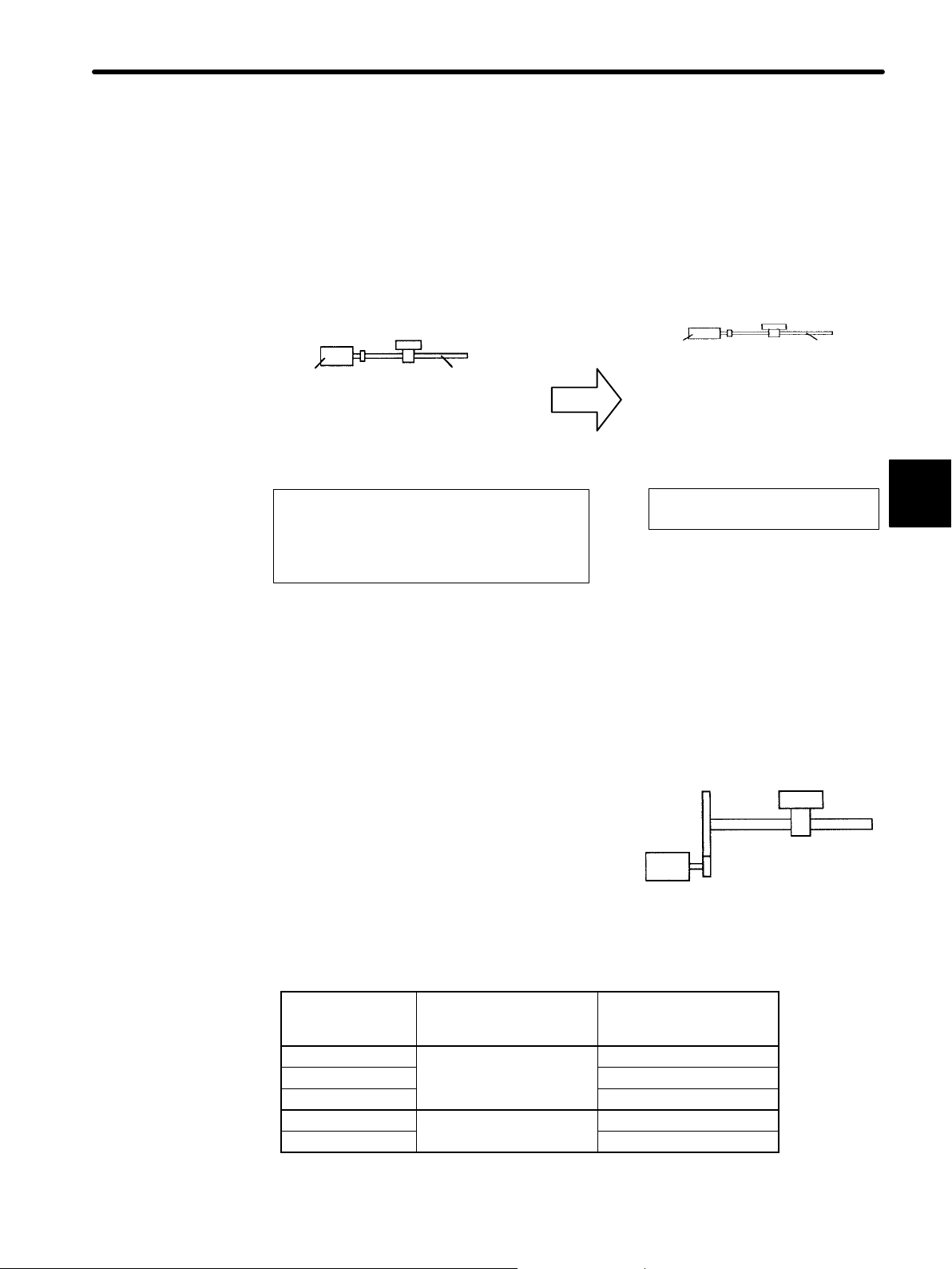
3.2.5 Using Electronic Gear
The electronic gear function enables the motor travel distance per input reference pulse
to be set to any value. It allows the host controller to perform control without having to
consider the machine gear ratio and the number of encoder pulses.
3.2 Setting Parameters According to Host Controller
When Electronic Gear Function
is Not Used
Workpiece
Number of
encoder
pulses: 2,048
To move a workpiece 10 mm :
One revolution is equivalent to 6 mm, so
10 6 = 1.6666 (revolutions)
2048 x 4 (pulses) is equivalent to one revolution, so
1.6666 x 2,048 x 4 = 13,653 (pulses)
A total of 13653 pulses must be input as a reference.
The host controller needs to make this calculation.
Ball screw
pitch: 6 mm
When Electronic Gear Function
is Used
Workpiece
Number of
encoder
pulses: 2,048
Machine conditions and reference unit
must be defined for the electronic gear
function beforehand.
To move a workpiece 10 mm:
Reference unit is 1 μm, so
10 mm 1 μm = 10,000 pulses
Reference
unit: 1 μm
Ball screw
pitch: 6 mm
J Setting the Electronic Gear
Calculate the electronic gear ratio (B/A) according to the procedure below and set the
value in Cn-24 and Cn-25.
3
1. Check the machine specifications.
Items related to electronic gear:
− Gear ratio
− Ball screw pitch
Gear ratio
− Pulley diameter
2. Check the number of encoder pulses for the SGMj servomotor.
Motor Type
encoder
specifications
2
3 2048
6 4096
W
S 8192
Encoder Type Number of Encoder
Pulses Per Revolution
Incremental encoder
Absolute encoder
(P/R)
8192
1024
Same as parameter Cn-11 settings.
Ball screw pitch
79
Page 92

APPLICATIONS OF Σ-SERIES PRODUCTS
3.2.5 Using Electronic Gear
3. Determine the reference unit to be used.
3
Reference unit is the minimum unit of position
data used for moving the load.
To move a table in 0.001 mm units
Reference unit: 0.001 mm
(Minimum unit of reference from host controller)
Examples:
0.01 mm, 0.001 mm, 0.1°, 0.01 inch
Determine the reference unit according to
Reference input of one pulse moves the load
machine specifications and positioning
accuracy.
by one reference unit.
Example: When reference unit is 1 μm
If a reference of 50,000 pulses is input, the load moves 50 mm (50,000 x 1 μm).
4. Determine the load travel distance per revolution of load shaft in reference units.
Load travel distance per revolution of load shaft (in reference units)
Load travel distance per revolution of load shaft (in unit of distance)
=
Reference unit
Example: When ball screw pitch is 5 mm and reference unit is 0.001 mm
5/0.001 = 5,000 (reference units)
Ball Screw Disc Table Belt & Pulley
Load shaft
1 revolution
=
P: Pitch
P
Reference unit
1 revolution
5. Determine the electronic gear ratio
=
B
A
Load shaft
360°
Reference unit
.
Load shaft
1 revolution
If the load shaft makes “n” revolutions when the motor shaft makes “m” revolutions,
the gear ratio of motor shaft and load shaft is
B
Electronic gear ratio
Travel distance per revolution of load shaft (in reference units)
=
A
Number of encoder pulses x 4
n
.
m
×
NOTE Make sure that the electronic gear ratio meets the following condition:
B
0.01 ≤ Electronic gear ratio ≤ 100
A
If the electronic gear ratio is outside this range, the SERVOPACK does not work properly. In this case, modify the load configuration or reference unit.
D: Pulley diameter
π D
=
Reference unit
m
n
80
Page 93

3.2 Setting Parameters According to Host Controller
6. Set the electronic gear ratio in the parameters below.
B
Reduce the electronic gear ratio
integer smaller than 65535, then set A and B in the following parameters.
to their lowest terms so that both A and B are an
A
B
A
This is all that is required to set the electronic gear.
Cn-24
Cn-25
Set the electronic gear ratio according to machine
specifications.
Electronic gear ratio
B = [(Number of encoder pulses) x 4] x [Motor shaft rotating speed]
A = [Reference unit (load travel distance per revolution of load shaft)] x [Load shaft
Cn-24 RATB Electronic gear ratio (numerator)
Cn-25 RATA Electronic gear ratio (denominator)
RATB
Electronic Gear Ratio
(Numerator)
RATA
Electronic Gear Ratio
(Denominator)
B
A
rotating speed]
=
Unit:
None
Unit:
None
Cn-24
Cn-25
Setting
Range: 1
to 65535
Setting
Range: 1
to 65535
Factory
Setting: 4
Factory
Setting: 1
Input
reference
pulse
For Position
Control Only
For Position
Control Only
SGDB
SERVOPACK
Electronic gear
SGMj
servomotor
3
Note that the parameter settings must meet the following condition:
0.01 ≤
B
A
≤ 100
81
Page 94

APPLICATIONS OF Σ-SERIES PRODUCTS
3.2.5 Using Electronic Gear
J Examples of Setting an Electronic Gear Ratio for Different Load Mechanisms
Ball Screw
Reference unit: 0.001 mm
Load shaft
Travel distance per
revolution of load shaft
Electronic gear ratio
=
B
A
6mm
0.001mm
2048 × 4 × 1
=
6000 × 1
= 6000
=
Cn-24
Cn-25
3
Incremental
encoder:
2048 pulses per revolution
Ball screw
pitch: 6 mm
Disc Table
Reference unit:
0.1°
Load shaft
Incremental encoder:
2048 pulses per revolution
Belt & Pulley
Reference unit: 0.0254 mm
Load shaft
Gear ratio:
2.4 : 1
Absolute encoder:
1024 pulses per revolution
Pulley diameter:
100 mm
Gear ratio:
3:1
Travel distance per
revolution of load shaft
Electronic gear ratio
Preset
values
Travel distance per
revolution of load shaft
Electronic gear ratio
=
9830.4
12362
=
49152
61810
Preset
values
=
B
A
B
A
3.14x100
=
Preset
values
Cn-24
Cn-25
360°
=
=
Cn-24
Cn-25
0.0254
1024 × 4 × 2.4
12362 × 1
= 3600
0.1°
2048 × 4 × 3
3600 × 1
24576
3600
mm
mm
Cn-24
Cn-25
8192
6000
=
= 12362
Cn-24
=
Cn-25
49152
61810
Cn-24
Cn-25
82
J Control Block Diagram for Position Control
SGDB SERVOPACK for position control
Feed−
forward
gain
Frequency
dividing
Error
counter
Reference
pulse
PG signal
output
Differentiation
Smoothing
Primary
lag filter
Bias
Speed
loop
/COIN
signal
Current
loop
SGMj
servomotor
Encoder
Page 95

3.2.6 Using Contact Input Speed Control
The contact input speed control function provides easy-to-use speed control. It allows
the user to initially set three different motor speeds in parameters, select one of the
speeds externally by contact input and run the motor.
SGDB SERVOPACK
3.2 Setting Parameters According to Host Controller
/P-CON
Contact
input
No external speed setting
device or pulse generator is
required.
J
Using the Contact Input Speed Control Function
/P-CL
/N-CL
1CN-41
1CN-45
1CN-46
SGMj
servomotor
Speed selection
The motor is operated at the
speed set in the parameter.
Parameters
To use the contact input speed control function, perform Steps a) to c).
1. Set memory switch Cn-02 as follows.
Cn-2B
Control Mode Selection Factory
Setting: 0
For Speed/Torque Control
and Position Control
3
Enables the contact input speed control function.
If the contact input speed control function is
used, the contents of the input signals shown be-
Contact input
SERVOPACK
Run the
motor at
internally
set
speed
Servomotor
low will change.
When this memory switch is reset, the meanings of the following signals will also
change:
Monitor mode (Un-05) bit 7 and bit 8
83
Page 96

APPLICATIONS OF Σ-SERIES PRODUCTS
the
contact
10,1
1
input
speed
NoteInth
the
posi
pulse
in
3.2.6 Using Contact Input Speed Control
Setting Meaning Input Signal
3
0, 1, 2,
7, 8, 9,
Does not use
input speed
control function.
/P-CON (1CN-41) Used to switch between P control and PI
control and to perform other functions.
/P-CL (1CN-45) Used for forward external current limit input
/N-CL (1CN-46) Used for reverse external current limit input
Uses the
contact input
3, 4, 5,
6
speed control
function.
case of
the position control type,
thereference
/P-CON /P-CL /N-CL Speed Setting
e
Direction
of rotation
0: Forward
1: Reverse
0 0 0 reference and so on
0 1 Cn-1F, SPEED1
1 1 Cn-20, SPEED2
pulse inhibit func-
1 0 Cn-21, SPEED3
tion (INHIBIT)
cannot be
used.
2. Set three motor speeds in the following parameters.
0: OFF, 1: ON
Cn-1F
Cn-20
Cn-21
SPEED1
1st Speed (Contact
Input Speed Control)
SPEED2
2nd Speed (Contact
Input Speed Control)
SPEED3
3rd Speed (Contact
Input Speed Control)
Unit:
min
Unit:
min
Unit:
min
Setting
−1
Range: 0 to
10000
Setting
−1
Range: 0 to
10000
Setting
−1
Range: 0 to
10000
Use these parameters to set motor speeds
when the contact input speed control function
is used.
If a value higher than the maximum speed is
set, the maximum speed value is used.
Speed selection input signals /P-CL (1CN-45)
and /N-CL (1CN-46), and rotation direction
selection signal /P-CON (1CN-41) enable the
motor to run at the preset speeds.
3. Set the soft start time.
Cn-07
Cn-23
SFSACC
Soft Start Time
(Acceleration)
SFSDEC
Soft Start Time
(Deceleration)
Unit:msSetting
Unit:msSetting
Range: 0
to 10000
Range: 0
to 10000
Factory
Setting:
100
Factory
Setting:
200
Factory
Setting:
300
Contact input speed control
Contact
input
Factory
Setting: 0
Factory
Setting: 0
For Speed Control only
For Speed Control only
For Speed Control only
SERVOPACK
Run the
motor at
internally
set speed
Servomotor
For Speed Control only
For Speed Control only
84
Page 97

3.2 Setting Parameters According to Host Controller
Selected
S
d
0
0
rotation
6
In the SERVOPACK,a speed reference is multiplied by the preset acceleration or deceleration value to provide speed control.
When a progressive speed reference is input
or contact input speed control is used, smooth
speed control can be performed. (For normal
Cn-07: Set this time interval.
speed control, set “0” in each parameter.)
Set the following value in each parameter.
Cn-23: Set this time interval.
•
Cn-07: Time interval from the time the motor starts until it reaches the maximum
speed
•
Cn-23: Time interval from the time the motor is running at the maximum speed until it
stops
J
Operating by Contact Input Speed Control Function
Contact input speed control performs the following operation.
The following input signals are used to start and stop the motor.
Speed
reference
SERVOPACK
contact input
speed
reference
Soft start
Maximum
speed
Maximum
speed
3
Speed Selection 1 (Forward
→ Input /P-CL 1CN-45
→ Input /N-CL 1CN-46
External Torque Limit Input)
Speed Selection 2 (Reverse
External Torque Limit Input)
When Contact Input Speed Control is used:
Contact Signal Parameter
/P-CON /P-CL /N-CL Cn-2B
3
4
−−−−
5
6
Direction of
rotation
0: Forward
rotation
1: Reverse
rotation
0 1 SPEED 1 (Cn-1F)
1 1
1 0
Common to 3, 4, 5 and
6
For Speed/Torque
Control and
Position Control
For Speed/Torque
Control and
Position Control
pee
Stopped by internal speed reference 0
Analog speed reference input
(V-REF)
Pulse reference input (position
control)
Analog torque reference input
(torque control)
SPEED 2 (Cn-20)
SPEED 3 (Cn-21)
−−−−: Not used
Modes Other Than Contact Input Speed Control
Input signals are used as external torque limit input.
85
Page 98
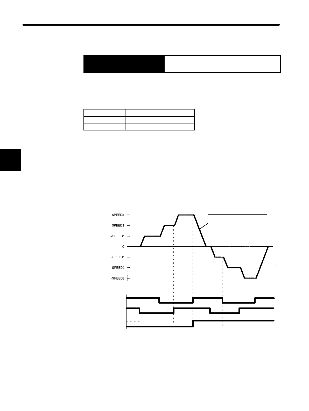
APPLICATIONS OF Σ-SERIES PRODUCTS
3.2.6 Using Contact Input Speed Control
Input signal /P-CON is used to specify the direction of motor rotation.
3
Proportional Control, etc. For Speed/Torque
→ Input /P-CON 1CN-41
Control and
Position Control
When Contact Input Speed Control is used:
Use input signal /P-CON to specify the direction of motor rotation.
/P-CON Meaning
1 Reverse rotation
0 Forward rotation
0: OFF (high level), 1: ON (low level)
Modes Other Than Contact Input Speed Control
/P-CON signal is used for proportional control, zero-clamp and torque/speed control
changeover.
The figure below illustrates an example of operation in contact input speed control mode.
Using the soft start function reduces physical shock at speed changeover.
When Contact Input Speed Control is Used
Motor speed
2nd speed
1st speed
3rd speed
Set acceleration and
deceleration values in Cn-07
and Cn-23 (soft start time).
/P-CL
/N-CL
/P-CON
Stopped
Stopped
1st speed
2nd speed
3rd speed
OFF OFF OFF OFF OFF
ON ON
ON
OFFOFFOFF
ONONON
ON
ONONONON
OFF
ON
Stopped
OFFOFF
OFFOFFOFFOFF
86
Page 99

3.2 Setting Parameters According to Host Controller
Note When the parameter Cn-2B is set to 5, the soft start function works only in contact
input speed control mode. The soft start function is not available when pulse reference input is used.
If contact input speed control mode is switched to pulse reference input mode
when the motor is running at the 1st, 2nd or 3rd speed, the SERVOPACK does not
receive a pulse reference until positioning complete signal /COIN is output.
Always start outputting a pulse reference from the host controller after a positioning complete signal is output from the SERVOPACK.
Signal Generation Timing for Position Control Type
Motor speed
−1
0 min
/COIN
Pulse reference
/N-CL
/P-CL
Selected speed
1st speed
The above figure illustrates signal generation timing when the soft start function is
used.
The value of t
is not influenced by use of the soft start function.
1
A maximum of 6 ms delay occurs when /P-CL or /N-CL signal is read.
3.2.7 Using Torque Control
The SERVOPACK can provide the following torque control:
• Torque restriction Level 1: To restrict the maximum output torque to protect
2nd speed
3rd speed
Pulse reference
the machine or workpiece
Level 2: To restrict torque after the motor moves the
machine to a specified position
3
1st speed
• Torque control Level 3: To always control output torque, not speed
Level 4: To switch between torque control and other
control
This section describes how to use levels 3 and 4 of the torque control function.
87
Page 100

APPLICATIONS OF Σ-SERIES PRODUCTS
p
be
usedasspeed
limit
when
bit2of
Cn-02
3.2.7 Using Torque Control
J Selecting Torque Control
Use the following parameter to select level 3 or level 4 torque control.
3
Cn-2B
Control Mode Selection Factory
Setting: 0
For Speed/Torque Control
and position Control
This is dedicated torque control.
A motor torque reference value is externally input into the SERVOPACK to control
torque.
Examples of Use: Tension control
Pressure control
Cn-2B Control Mode
Torque Control
This is a dedicated torque control mode.
• A torque reference is input from T-REF
Torque
reference
Speed limit
(1CN-9).
• /P-CON is not used.
• Speed reference input V-REF (1CN-5) can
2
be used as s
is set to 1.
eed limit when bit 2 of Cn-02
• Parameter Cn-14 can be used for maximum
speed control.
Example of Use:
Tension control
Tension
SGDB
SERVOPACK
SERVOPACK
88
Torque Control $ Speed Control (Analog
Reference)
Torque control and speed control can be
switched.
• A speed reference or speed limit value is
input from V-REF (1CN-5).
• T-REF (1CN-9) inputs a torque reference,
9
torque feed-forward reference or torque limit
value depending on the control mode used.
Speed
reference
Torque
reference
Switching
between
speed
and
torque
reference
/P-CON
SERVOPACK
1CN-5
1CN-9
1CN-11
• /P-CON (1CN-41) is used to switch between
torque control and speed control.
When 1CN-41 is
open
When 1CN-41 is
at 0 V
Torque
control
Speed
control
 Loading...