

Page 1
-7-Series AC Servo Drive
-7S/
-7W SERVOPACK with
Hardware Option Specifications
Dynamic Brake
Product Manual
SGD7S-020
SGD7W-020
MANUAL NO. SIEP S800001 73B
Basic Information on SERVOPACKs
Selecting a SERVOPACK
Selecting a Dynamic Brake Resistor
Wiring and Connecting
a Dynamic Brake Resistor
Basic Functions That Require
Setting before Operation
Maintenance
Parameter Lists
Appendices
1
2
3
4
5
6
7
8
9
10
Page 2

Copyright © 2015 YASKAWA ELECTRIC CORPORATION
All rights reserved. No part of this publication may be reproduced, stored in a
retrieval system, or transmitted, in any form, or by any means, mechanical, electronic, photocopying, recording, or otherwise, without the prior written permission
of Yaskawa. No patent liability is assumed with respect to the use of the information contained herein. Moreover, because Yaskawa is constantly striving to
improve its high-quality products, the information contained in this manual is subject to change without notice. Every precaution has been taken in the preparation
of this manual. Nevertheless, Yaskawa assumes no responsibility for errors or
omissions. Neither is any liability assumed for damages resulting from the use of
the information contained in this publication.
Page 3
About this Manual
This manual provides information on Σ-7-Series AC Servo Drives that support the dynamic brake
hardware option specifications (SGD7-020). It describes the specifications of
SERVOPACKs that are different from the SERVOPACKs that do not support the dynamic brake
hardware option specifications.
For all other information, refer to the product manual for a standard SERVOPACK.
Read and understand this manual and the standard SERVOPACK product manual to ensure correct usage of the Σ-7-Series AC Servo Drives.
Keep this manual and the standard SERVOPACK product manual in a safe place so that they can
be referred to whenever necessary.
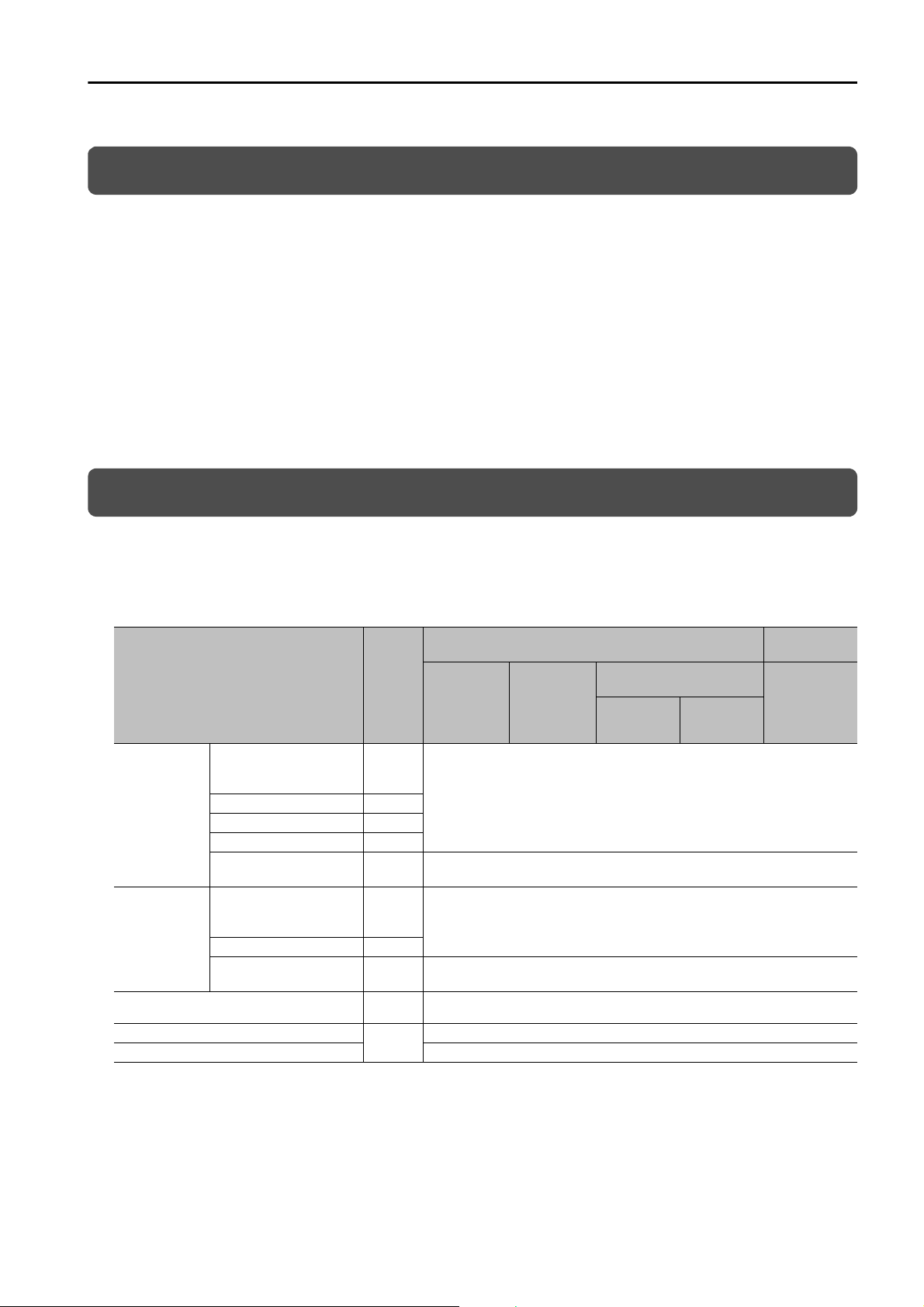
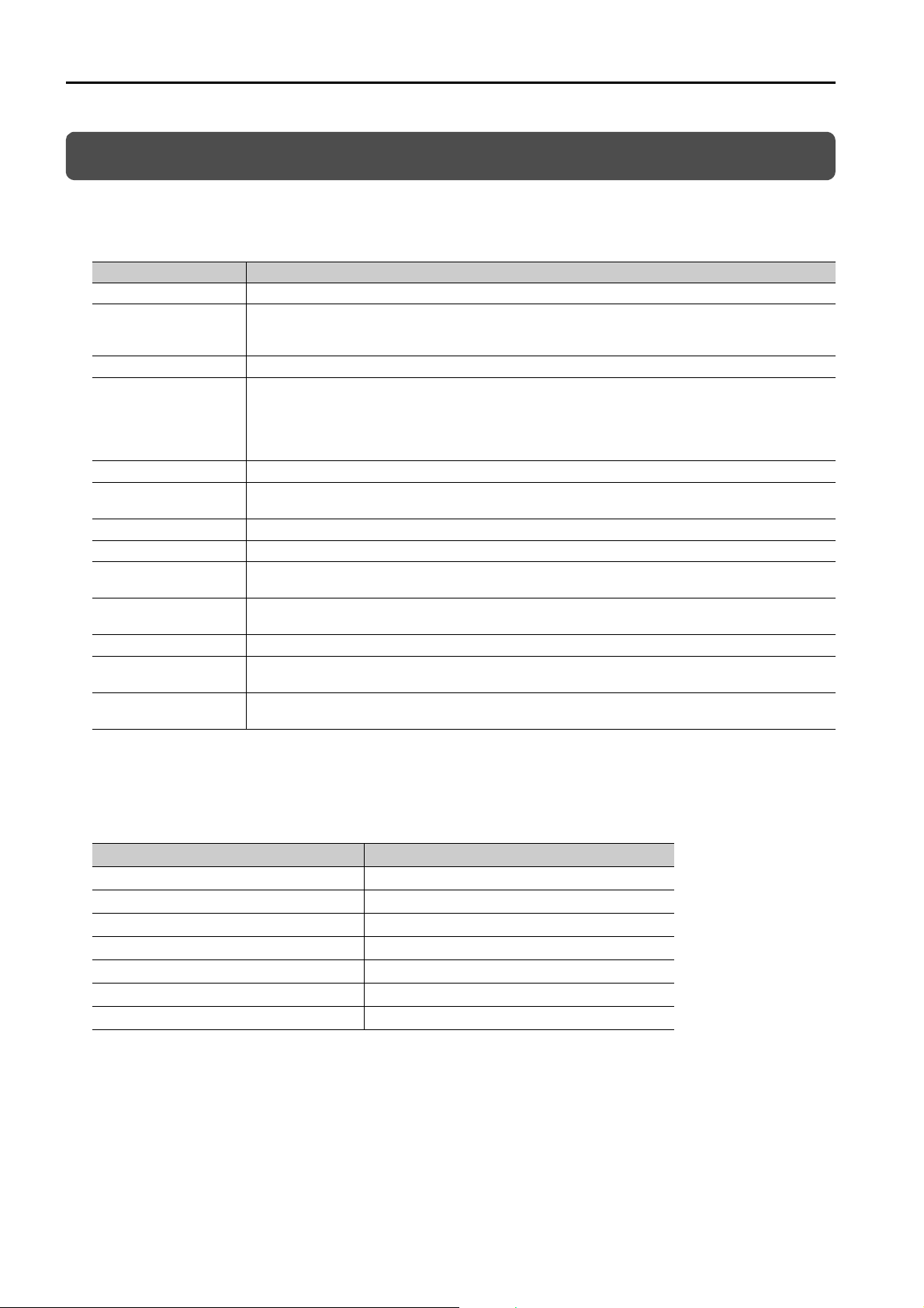
Finding Information
Information on SERVOPACKs that support the dynamic brake hardware option specifications is
provided in different manuals depending on the topic. Use the following table to find what information is provided in this manual and what information is provided in the standard SERVOPACK product manual.
Σ-7S SERVOPACKs
Item
About the Dynamic
Brake Hardware Option
Specifications
Basic Information on
SERVOPACKs
Selecting a
SERVOPACK
Dynamic Brake Resistor Selection
SERVOPACK Installation
Wiring and Connecting SERVOPACKs Chapter 4
Nameplate 1.2
Part Names 1.3
Model Designations 1.4
Other basic information
not listed above
Combinations of Servo-
motors and SERVO-
PAC Ks
External Dimensions 2.2
Other selection informa-
tion not listed above
This
Manual
1.1
− Chapter 1
2.1
− Chapter 2
Chapter
3
−
Analog
Volta ge/
Pulse Train
References
MECHA-
TROLINK-II/
-III Communications
References
Command Option
Attachable
INDEXER
Module
−
−
−
Chapter 3
DeviceNet
Module
Continued on next page.
Σ-7W
SERVOPACKs
MECHA-
TROLINK-III
Communica-
tions
References
iii
Page 4
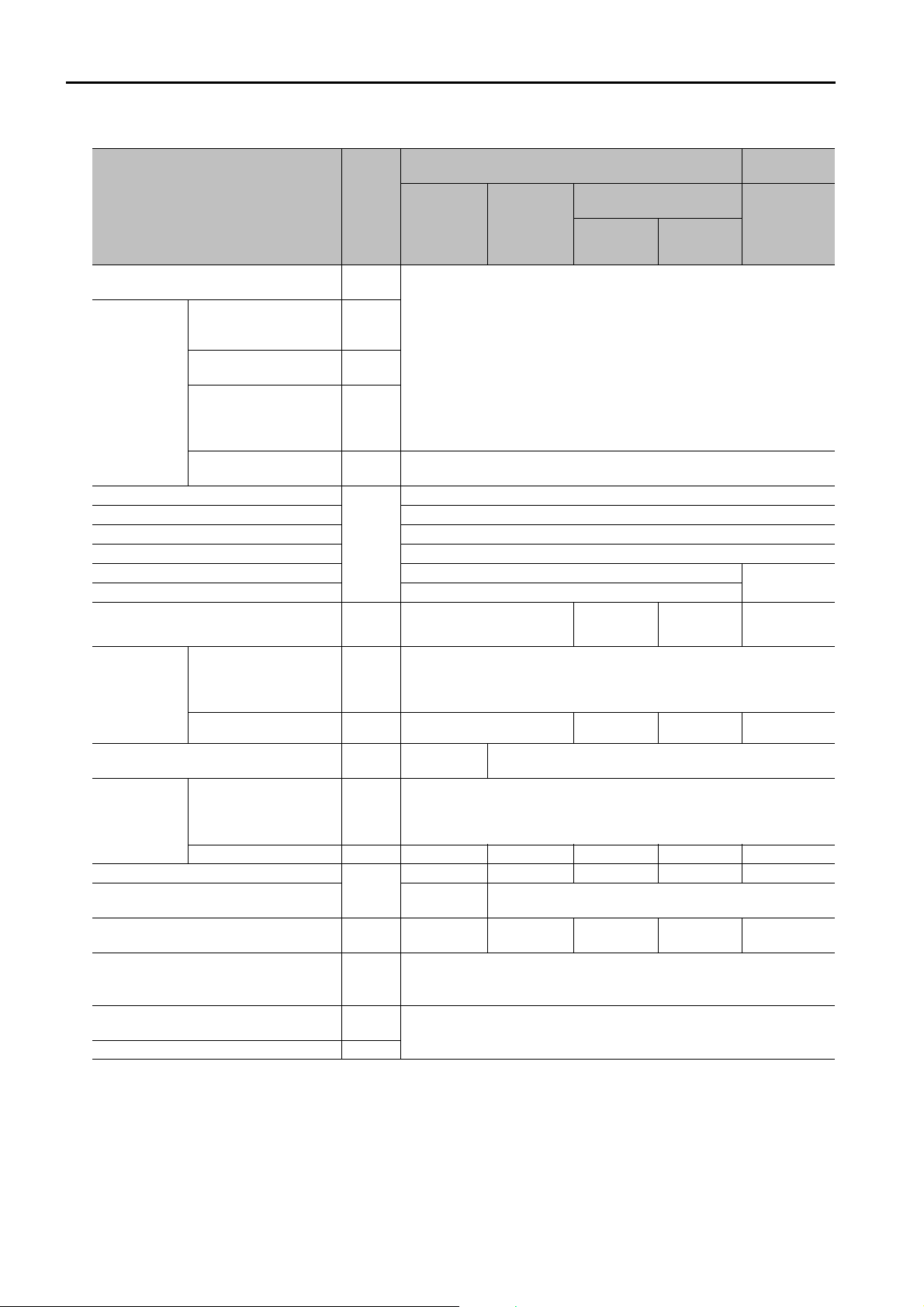
Σ-7S SERVOPACKs
Item
Dynamic Brake Resistor Wiring and Connections
Motor Stopping Methods
for Servo OFF and
Alarms
Basic Information Required
for Settings
before Operation
Application Functions
Trial Operation and Actual Operation Chapter 7
Tuning Chapter 8
Monitor Chapter 9
Fully-Closed Loop Control Chapter 10
Safety Control Chapter 11
Option Module Functions −−
Maintenance
Panel Displays and Panel Operator Procedures
Parameter List
Interpreting the Panel Display
Examples of Connections to Host Controllers
Corresponding SERVOPACK and
SigmaWin+ Function Names
Motor Stopping Method
for Overtravel
Setting the Energy Consumption and Resistance of the Dynamic
Resistor
Other basic functions
not listed above
Troubleshooting Related
to the Dynamic Brake
Hardware Option Specifications
All other troubleshooting − Chapter 12 Chapter 15 Chapter 14 Chapter 10
Parameters Related to
the Dynamic Brake Hardware Option Specifications
All other parameters − Chapter 14 Chapter 13 Chapter 16 Chapter 15 Chapter 11
This
Manual
Chapter
4
5.2
5.3
5.4
− Chapter 5
−
Chapter
6
− Chapter 13 −
Chapter
7
−
− 15.2 14.2 17.1 16.1 12.2
Analog
Voltage/
Pulse Train
References
– 14.1 1.3 1.5 12.1
15.1 −
MECHA-
TROLINK-II/
-III Communications
References
Continued from previous page.
Command Option
Attachable
INDEXER
Module
−
Chapter 6
Chapters 12,
13, 14, and
17
−
−
DeviceNet
Module
Chapters 12,
13, and 16
Σ-7W
SERVOPACKs
MECHA-
TROLINK-III
Communica-
tions
References
−
−
iv
Monitor Displays for the Dynamic Brake
Hardware Option Specifications
Coasting Distance when Stopping with
the Dynamic Brake
Data for Coasting Distance Calculation 8.3
8.1 −
8.2
−
Page 5
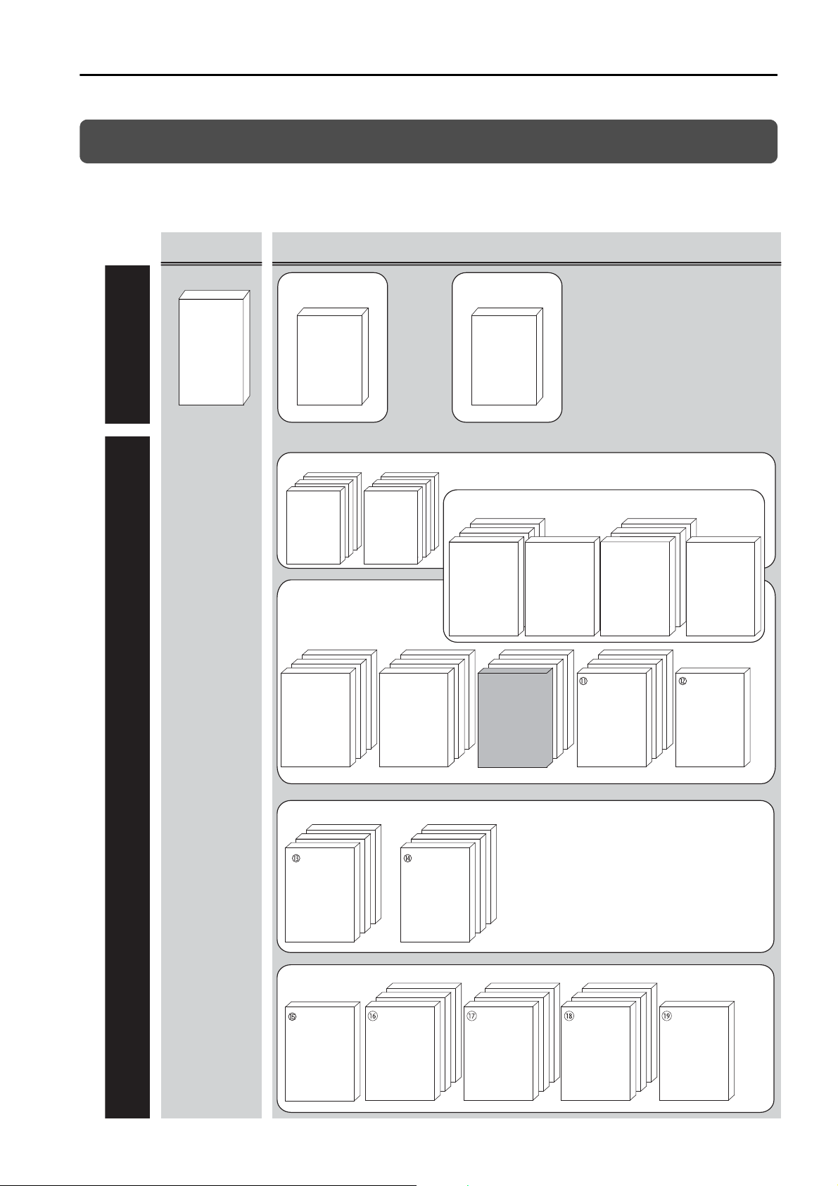
Related Documents
Manuals Catalogs
Σ-7-Series
Operation
Interface
Operating
Manuals
System Components
Machine
Controller
and
Servo Drive
General
Catalog
MP3300
Catalog
Machine Controllers
Σ-7-Series
Catalog
Servo Drives
Machine Controllers
SERVOPACKs:
Σ-7S and Σ-7W
SERVOPACKs with Built-in Controllers:
Σ-7C
Servomotors
Other Documents
Built-in
Function
Manuals
Σ-7-Series
Σ-7S/Σ-7W
SERVOPACK
Product
Manuals
Σ-7-Series
Σ-7S/Σ-7W
SERVOPACK
Hardware Option
Product Manuals
(such as this manual)
Option
Module
User’s
Manuals
Σ-7-Series
Σ-7S/Σ-7W
SERVOPACK
FT/EX
Product Manuals
Option
Module
User’s
Manual
Σ-7-Series
Servomotor
Product
Manuals
Σ-7-Series
Σ-7C
SERVOPACK
Product Manual
Σ-7-Series
Σ-7C
SERVOPACK
Troubleshooting
Manual
Enclosed
Documents
Enclosed
Documents
Built-in
Function
Manuals
Enclosed
Documents
Σ-7-Series
Peripheral
Device
Selection
Manual
Σ-7-Series
MECHATROLINK
Communications
Command
Manuals
Programming
Manuals
Distributed
I/O Module
User’s
Manual
The relationships between the documents that are related to the Servo Drives are shown in the following
figure. The numbers in the figure correspond to the numbers in the table on the following pages. Refer
to these documents as required.
v
Page 6

Classification Document Name Document No. Description
Machine Controller and
Servo Drive
General Catalog
MP3300 Catalog
Σ-7-Series Catalog
Built-in Function Manuals
Option Module
User’s Manuals
Machine Controller and
AC Servo Drive
Solutions Catalog
Machine Controller
MP3300
AC Servo Drives
Σ-7 Series
Σ-7-Series AC Servo Drive
Σ-7C SERVOPACK
Motion Control
User’s Manual
Machine Controller
MP3000 Series
Communications
User’s Manual
Machine Controller
MP2000 Series
Communication Module
User’s Manual
Machine Controller
MP2000 Series
262IF-01 FL-net
Communication Module
User’s Manual
Machine Controller
MP2000 Series
263IF-01 EtherNet/IP
Communication Module
User’s Manual
Machine Controller
MP2000 Series
I/O Module
User’s Manual
Machine Controller
MP2000 Series
Analog Input/Analog Output
Module AI-01/AO-01
User’s Manual
Machine Controller
MP2000 Series
Counter Module CNTR-01
User’s Manual
KAEP S800001 22
KAEP C880725 03
KAEP S800001 23
SIEP S800002 03
SIEP C880725 12
SIEP C880700 04
SIEP C880700 36
SIEP C880700 39
SIEP C880700 34
SIEP C880700 26
SIEP C880700 27
Describes the features and application examples for combinations of
MP3000-Series Machine Controllers and Σ-7-Series AC Servo
Drives.
Provides detailed information on
MP3300 Machine Controllers,
including features and specifications.
Provides detailed information on Σ-
7-Series AC Servo Drives, including
features and specifications.
Provides detailed information on
the specifications, system configuration, and application methods of
the Motion Control Function Modules (SVD, SVC4, and SVR4) for Σ-
7-Series Σ-7C SERVOPACKs.
Provides detailed information on
the specifications, system configuration, and communications connection methods for the Ethernet
communications that are used with
MP3000-Series Machine Controllers and Σ-7-Series Σ-7C SERVOPAC Ks.
Provide detailed information on the
specifications and communications methods for the Communications Modules that can be mounted
to MP3000-Series Machine Controllers and Σ-7-Series Σ-7C
SERVOPACKs.
Provide detailed information on the
specifications and communications methods for the I/O Modules
that can be mounted to MP3000Series Machine Controllers and Σ-
7-Series Σ-7C SERVOPACKs.
Continued on next page.
vi
Page 7

Continued from previous page.
Classification Document Name Document No. Description
Enclosed Documents
Σ-7-Series AC Servo Drive
Σ-7S and Σ-7W SERVOPACK
Safety Precautions
Σ-V-Series/Σ-V-Series
for Large-Capacity Models/
Σ-7-Series
Safety Precautions
Option Module
Σ-V-Series/Σ-V-Series
for Large-Capacity Models/
Σ-7-Series
Installation Guide
Command Option Module
Σ-V-Series/Σ-V-Series
for Large-Capacity Models/
Σ-7-Series
Installation Guide
Fully-closed Module
TOMP C710828 00
TOBP C720829 00
TOBP C720829 01
TOBP C720829 03
Provides detailed information for
the safe usage of Σ-7-Series
SERVOPACKs.
Provides detailed information for
the safe usage of Option Modules.
Provides detailed procedures for
installing the Command Option
Module in a SERVOPACK.
Provides detailed procedures for
installing the Fully-closed Module in
a SERVOPACK.
Σ-7-Series
Σ-7C SERVOPACK
Product Manual
Σ-7-Series
Σ-7C SERVOPACK
Troubleshooting
Manual
Σ-V-Series/Σ-V-Series
for Large-Capacity Models/
Σ-7-Series
Installation Guide
Safety Module
Σ-V-Series/Σ-V-Series
for Large-Capacity Models/
Σ-7-Series
Installation Guide
INDEXER Module
Σ-V-Series/Σ-V-Series
for Large-Capacity Models/
Σ-7-Series
Installation Guide
DeviceNet Module
Σ-7-Series AC Servo Drive
Σ-7C SERVOPACK
Product Manual
Σ-7-Series AC Servo Drive
Σ-7C SERVOPACK
Troubleshooting Manual
TOBP C720829 06
TOBP C720829 02
TOBP C720829 07
SIEP S800002 04
SIEP S800002 07
Provides detailed procedures for
installing the Safety Module in a
SERVOPACK.
Provides detailed procedures for
installing the INDEXER Module in a
SERVOPACK.
Provides detailed procedures for
installing the DeviceNet Module in a
SERVOPACK.
Provides detailed information on
selecting Σ-7-Series Σ-7C SERVOPACKs; installing, connecting, setting, testing in trial operation, and
tuning Servo Drives; writing, monitoring, and maintaining programs;
and other information.
Provides detailed troubleshooting
information for Σ-7-Series Σ-7C
SERVOPACKs.
Continued on next page.
vii
Page 8

Σ-7-Series
Σ-7S/Σ-7W
SERVOPACK
Product Manuals
Continued from previous page.
Classification Document Name Document No. Description
Σ-7-Series AC Servo Drive
Σ-7S SERVOPACK with
MECHATROLINK-III
Communications References
Product Manual
Σ-7-Series AC Servo Drive
Σ-7S SERVOPACK with
MECHATROLINK-II
Communications References
Product Manual
Σ-7-Series AC Servo Drive
Σ-7S SERVOPACK with
Analog Voltage/Pulse Train
References
Product Manual
Σ-7-Series AC Servo Drive
Σ-7S SERVOPACK
Command Option Attachable
Type with INDEXER Module
Product Manual
SIEP S800001 28
SIEP S800001 27
SIEP S800001 26
SIEP S800001 64
Provide detailed information on
selecting Σ-7-Series SERVOPACKs and information on installing, connecting, setting, performing
trial operation for, tuning, and monitoring the Servo Drives.
Σ-7-Series
Σ-7S/Σ-7W
SERVOPACK with
Hardware Option
Specifications
Product Manuals
Σ-7-Series AC Servo Drive
Σ-7S SERVOPACK
Command Option Attachable
Type with DeviceNet Module
Product Manual
Σ-7-Series AC Servo Drive
Σ-7W SERVOPACK with
MECHATROLINK-III
Communications References
Product Manual
Σ-7-Series AC Servo Drive
Σ-7S/Σ-7W SERVOPACK with
Hardware Option Specifications
Dynamic Brake
Product Manual
Σ-7-Series AC Servo Drive
Σ-7W/Σ-7C SERVOPACK with
Hardware Option Specifications
HWBB Function
Product Manual
SIEP S800001 70
SIEP S800001 29
This manual
(SIEP S800001 73)
Provide detailed information on
Hardware Options for Σ-7-Series
SERVOPACKs.
SIEP S800001 72
Continued on next page.
viii
Page 9

Continued from previous page.
Classification Document Name Document No. Description
Σ-7-Series AC Servo Drive
Σ-7-Series
Σ-7S/Σ-7W SERVOPACK
FT/EX
Product Manuals
Option Module
User’s Manual
Σ-7S SERVOPACK with
FT/EX Specification for Indexing Application
Product Manual
Σ-7-Series AC Servo Drive
Σ-7S SERVOPACK with
FT/EX Specification for Tracking Application
Product Manual
Σ-7-Series AC Servo Drive
Σ-7S SERVOPACK with
FT/EX Specification
for Application with Special
Motor,
SGM7D Motor
Product Manual
Σ-7-Series AC Servo Drive
Σ-7S SERVOPACK with
FT/EX Specification
for Press and Injection
Molding Application
Product Manual
Σ-7-Series AC Servo Drive
Σ-7S SERVOPACK with
FT/EX Specification
for Transfer and Alignment
Application
Product Manual
Σ-7-Series AC Servo Drive
Σ-7S SERVOPACK with
FT/EX Specification
for Torque/Force Assistance
for Conveyance Application
Product Manual
Σ-7-Series AC Servo Drive
Σ-7S SERVOPACK with
FT/EX Specification
for Cutting Application
Feed Shaft Motor
Product Manual
AC Servo Drives
Σ-V Series/Σ-V Series
for Large-Capacity Models/
Σ-7 Series
User’s Manual
Safety Module
SIEP S800001 84
SIEP S800001 89
SIEP S800001 91
SIEP S800001 94
SIEP S800001 95
SIEP S800002 09
SIEP S800002 10
SIEP C720829 06
Provide detailed information on the
FT/EX Option for Σ-7-Series
SERVOPACKs.
Provides details information
required for the design and maintenance of a Safety Module.
Enclosed Documents
AC Servo Drive
Rotary Servomotor
Safety Precautions
AC Servomotor
Linear Σ Series
Safety Precautions
TOBP C230260 00
TOBP C230800 00
Provides detailed information for
the safe usage of Rotary Servomotors and Direct Drive Servomotors.
Provides detailed information for
the safe usage of Linear Servomotors.
Continued on next page.
ix
Page 10

Continued from previous page.
Classification Document Name Document No. Description
Σ-7-Series AC Servo Drive
Rotary Servomotor
Product Manual
SIEP S800001 36
Σ-7-Series
Servomotor
Product Manuals
Σ-7-Series
Peripheral Device
Selection Manual
Σ-7-Series
MECHATROLINK
Communications
Command Manuals
Σ-7-Series AC Servo Drive
Linear Servomotor
Product Manual
Σ-7-Series AC Servo Drive
Direct Drive Servomotor
Product Manual
Σ-7-Series AC Servo Drive
Peripheral Device
Selection Manual
Σ-7-Series AC Servo Drive
MECHATROLINK-II
Communications
Command Manual
Σ-7-Series AC Servo Drive
MECHATROLINK-III
Communications
Standard Servo Profile
Command Manual
SIEP S800001 37
SIEP S800001 38
SIEP S800001 32
SIEP S800001 30
SIEP S800001 31
Provide detailed information on
selecting, installing, and connecting
the Σ-7-Series Servomotors.
Describes the peripheral devices
for a Σ-7-Series Servo System.
Provides detailed information on
the MECHATROLINK-II communications commands that are used
for a Σ-7-Series Servo System.
Provides detailed information on
the MECHATROLINK-III communications standard servo profile commands that are used for a Σ-7-
Series Servo System.
Programming
Manuals
Σ-7-Series
Operation Interface
Operating Manuals
Machine Controller
MP3000 Series
Ladder Programming
Manual
Machine Controller
MP3000 Series
Motion Programming
Manual
Machine Controller
MP2000/MP3000 Series
Engineering Tool
MPE720 Version 7
User’s Manual
Σ-7-Series AC Servo Drive
Digital Operator
Oper
at
ing Manual
AC Servo Drive
Engineering Tool
SigmaWin+
Operation Manual
SIEP C880725 13
SIEP C880725 14
SIEP C880761 03
SIEP S800001 33
SIET S800001 34
Provides detailed information on
the ladder programming specifications and instructions for MP3000Series Machine Controllers and Σ-
7-Series Σ-7C SERVOPACKs.
Provides detailed information on
the motion programming and
sequence programming specifications and instructions for MP3000Series Machine Controllers and Σ-
7-Series Σ-7C SERVOPACKs.
Describes in detail how to operate
MPE720 version 7.
Describes the operating procedures for a Digital Operator for a
Σ-7-Series Servo System.
Provides detailed operating procedures for the SigmaWin+ Engineering Tool for a Σ-7-Series Servo
System.
Continued on next page.
x
Page 11

Continued from previous page.
Classification Document Name Document No. Description
Describes the functions, specifications, operating methods, and
MECHATROLINK-III communications for the Remote I/O Modules
for MP2000/MP3000-Series
Machine Controllers.
Distributed
I/O Module
User’s Manuals
MECHATROLINK-III
Compatible I/O Module
User’s Manual
SIEP C880781 04
xi
Page 12
Using This Manual
Technical Terms Used in This Manual
The following terms are used in this manual.
Ter m Meaning
Servomotor A Σ-7-Series Rotary Servomotor, Direct Drive Servomotor, or Linear Servomotor.
A generic term used for a Σ-7-Series Rotary Servomotor (SGMMV, SGM7J, SGM7A, SGM7P,
Rotary Servomotor
Linear Servomotor
SERVOPACK
Servo Drive
Servo System
servo ON
servo OFF
base block (BB)
dynamic brake (DB)
servo lock
Main Circuit Cable
SigmaWin+
or SGM7G) or a Direct Drive Servomotor (SGM7D, SGM7E, SGM7F, SGMCV, or SGMCS).
The descriptions will specify when Direct Drive Servomotors are excluded.
A generic term used for a Σ-7-Series Linear Servomotor (SGLG, SGLF, or SGLT).
• A Σ-7-Series Σ-7S Servo Amplifier with Analog Voltage/Pulse Train References.
• A Σ-7-Series Σ-7S Servo Amplifier with MECHATROLINK-II Communications References.
• A Σ-7-Series Σ-7S Servo Amplifier with MECHATROLINK-III Communications References.
• A Σ-7-Series Σ-7W Servo Amplifier with MECHATROLINK-III Communications References.
• A Σ-7-Series Σ-7S Command Option Module Attachable-Type Servo Amplifier.
The combination of a Servomotor and SERVOPACK.
A servo control system that includes the combination of a Servo Drive with a host controller
and peripheral devices.
Supplying power to the motor.
Not supplying power to the motor.
Shutting OFF the power supply to the motor by shutting OFF the base current to the power
transistor in the SERVOPACK.
A brake that performs a quick stop of a Servomotor by connecting resistance between the
Servomotor terminals.
A state in which the motor is stopped and is in a position loop with a position reference of 0.
One of the cables that connect to the main circuit terminals, including the Main Circuit Power
Supply Cable, Control Power Supply Cable, and Servomotor Main Circuit Cable.
The Engineering Tool for setting up and tuning Servo Drives or a computer in which the Engineering Tool is installed.
Differences in Terms for Rotary Servomotors and Linear Servomotors
There are differences in the terms that are used for Rotary Servomotors and Linear Servomotors.
This manual primarily describes Rotary Servomotors. If you are using a Linear Servomotor, you
need to interpret the terms as given in the following table.
Rotary Servomotors Linear Servomotors
torque force
moment of inertia mass
rotation movement
forward rotation and reverse rotation forward movement and reverse movement
rotary encoder linear encoder
unit: min
unit: N·m unit: N
-1
unit: mm/s
xii
Page 13
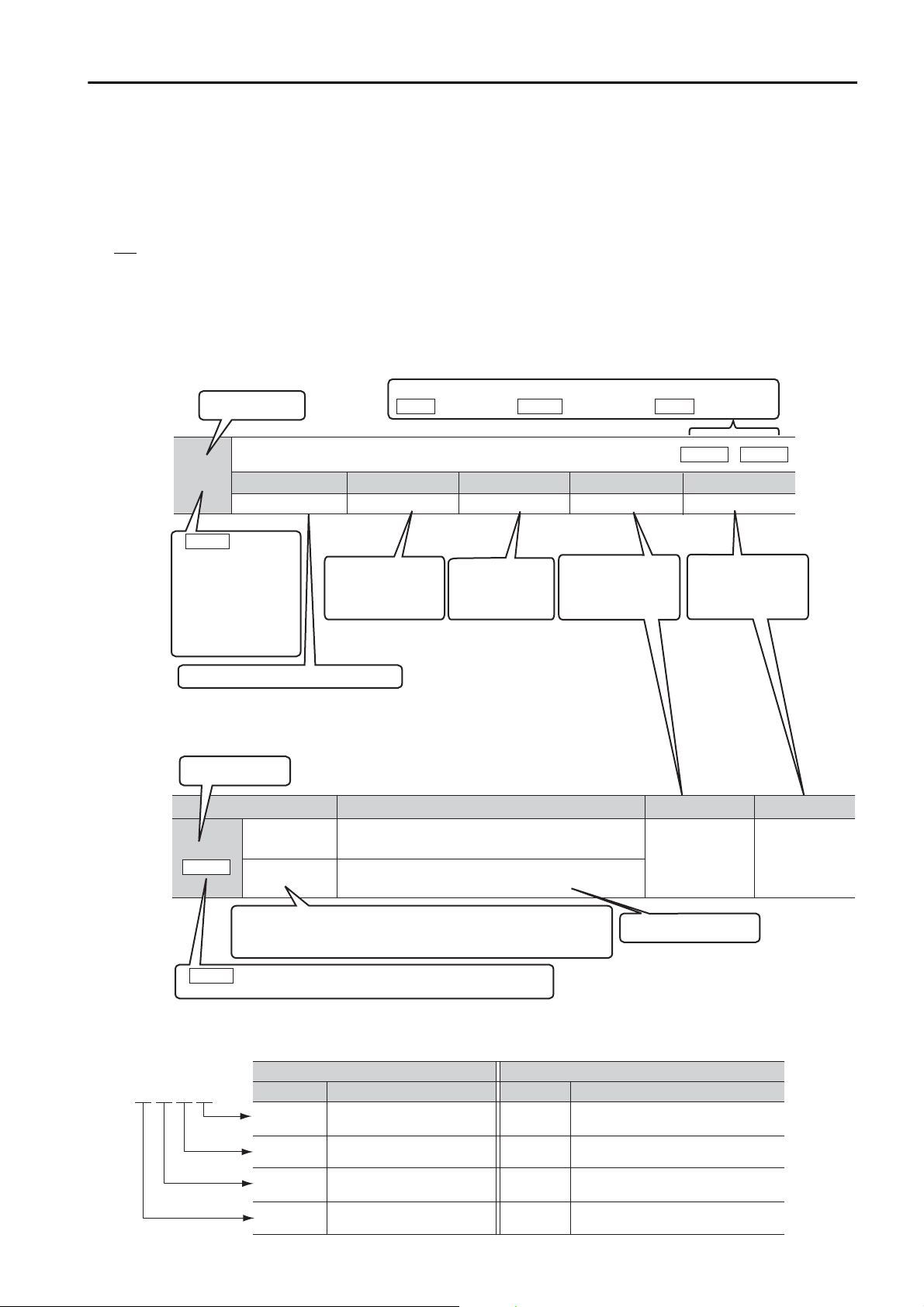
Notation Used in this Manual
n.0
(default setting)
Do not detect preventative maintenance warnings.
n.1
Detect preventative maintenance warnings.
Parameter Meaning When Enabled Classication
After startup Setup
This is the setting range for the parameter.
Pn00F
Parameter number
The notation “n.” indicates a parameter for selecting functions.
Each indicates the setting for one digit.
The notation shown here means that the first digit from the right is set to 1.
If All Axes is given here, the parameter applies to both axes A and B.
If you change the setting, the new setting will be applied to both axes.
Pn100
Speed Loop Gain
Position
Speed
Setting Range
10 to 20,000 0.1 Hz 400 Immediately
Setting Unit Default Setting When Enabled
Classication
Tuning
Parameter number
If All Axes is given
here, the parameter
applies to both axes A
and B.
If you change the
setting, the new setting
will be applied to both
axes.
All Axes
Position Torque
The control methods for which the parameters apply are given.
Speed
: Speed control : Position control : Torque control
This is the
parameter setting
before shipment.
This is when any
change made to the
parameter will
become effective.
This is the parameter
classication.
This is the minimum
unit (setting increment)
that you can set for
the parameter.
This column explains the
selections for the function.
•
Parameters for Selecting Functions
Notation Examples for Pn002
Pn002 =
n.
X
Indicates the rst digit from
the right in Pn002.
Pn002 =
n.
1
Indicates that the rst digit from
the right in Pn002 is set to 1.
Pn002 =
n.
X
Indicates the second digit
from the right in Pn002.
Pn002 =
n.
1
Indicates that the second digit from
the right in Pn002 is set to 1.
Pn002 =
n.
X
Indicates the third digit from
the right in Pn002.
Pn002 =
n.
1
Indicates that the third digit from
the right in Pn002 is set to 1.
Pn002 =
n.X
Indicates the fourth digit from
the right in Pn002.
Pn002 =
n.1
Indicates that the fourth digit from
the right in Pn002 is set to 1.
n.0 0 0 0
Notation
Digit Notation Numeric Value Notation
Meaning Notation Meaning
Notation for Reverse Signals
The names of reverse signals (i.e., ones that are valid when low) are written with a forward slash (/)
before the signal abbreviation.
Notation Example
BK
is written as /BK.
Notation for Parameters
The notation depends on whether the parameter requires a numeric setting (parameter for numeric
setting) or requires the selection of a function (parameter for selecting functions).
•
Parameters for Numeric Settings
Notation Example
xiii
Page 14
Example
Information
Engineering Tools Used in This Manual
This manual uses the interfaces of the SigmaWin+ for descriptions.
Trademarks
• QR code is a trademark of Denso Wave Inc.
• MECHATROLINK is a trademark of the MECHATROLINK Members Association.
• Other product names and company names are the trademarks or registered trademarks of the
respective company. “TM” and the
® mark do not appear with product or company names in this
manual.
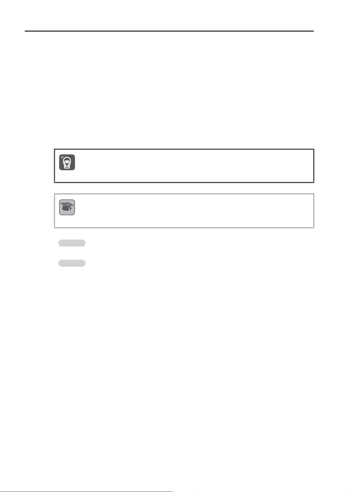
Visual Aids
The following aids are used to indicate certain types of information for easier reference.
Indicates precautions or restrictions that must be observed.
Important
Also indicates alarm displays and other precautions that will not result in machine damage.
Term
Indicates definitions of difficult terms or terms that have not been previously explained in this
manual.
Indicates operating or setting examples.
Indicates supplemental information to deepen understanding or useful information.
xiv
Page 15
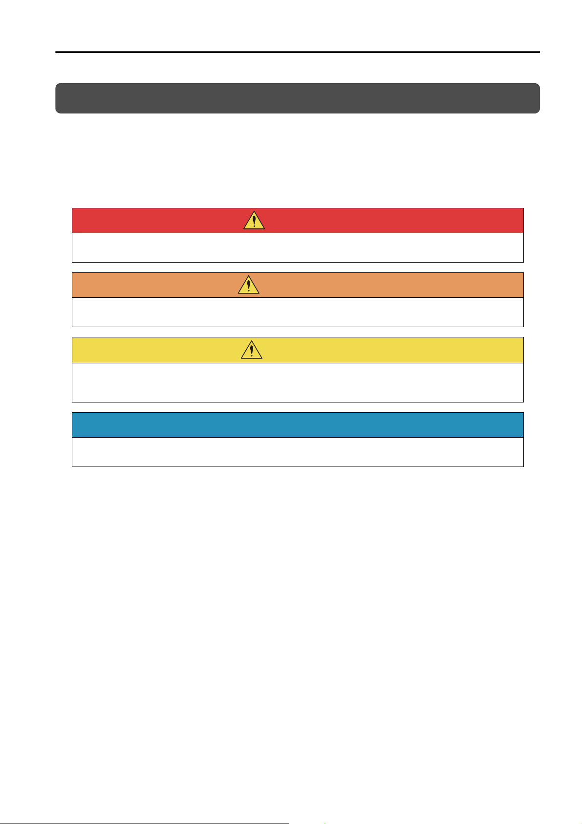
Safety Precautions
DANGER
WARNING
CAUTION
NOTICE
Safety Information
To prevent personal injury and equipment damage in advance, the following signal words are used
to indicate safety precautions in this document. The signal words are used to classify the hazards
and the degree of damage or injury that may occur if a product is used incorrectly. Information
marked as shown below is important for safety. Always read this information and heed the precautions that are provided.
Indicates precautions that, if not heeded, are likely to result in loss of life, serious injury, or fire.
Indicates precautions that, if not heeded, could result in loss of life, serious injury, or fire.
Indicates precautions that, if not heeded, could result in relatively serious or minor injury, or in
fire.
Indicates precautions that, if not heeded, could result in property damage.
xv
Page 16
DANGER
WARNING
CAUTION
Safety Precautions That Must Always Be Observed
General Precautions
Read and understand this manual to ensure the safe usage of the product.
Keep this manual in a safe, convenient place so that it can be referred to whenever necessary.
Make sure that it is delivered to the final user of the product.
Do not remove covers, cables, connectors, or optional devices while power is being supplied to
the SERVOPACK.
There is a risk of electric shock, operational failure of the product, or burning.
Use a power supply with specifications (number of phases, voltage, frequency, and AC/DC
type) that are appropriate for the product.
There is a risk of burning, electric shock, or fire.
Connect the ground terminals on the SERVOPACK and Servomotor to ground poles according
to local electrical codes (100 Ω or less for a SERVOPACK with a 100-VAC or 200-VAC power
supply, and 10 Ω or less for a SERVOPACK with a 400-VAC power supply).
There is a risk of electric shock or fire.
Do not attempt to disassemble, repair, or modify the product.
There is a risk of fire or failure.
The warranty is void for the product if you disassemble, repair, or modify it.
The SERVOPACK heat sinks, regenerative resistors, external dynamic brake resistors, Servo-
motors, and other components can be very hot while power is ON or soon after the power is
turned OFF. Implement safety measures, such as installing covers, so that hands and parts
such as cables do not come into contact with hot components.
There is a risk of burn injury.
For a 24-VDC power supply, use a power supply device with double insulation or reinforced
insulation.
There is a risk of electric shock.
Do not damage, pull on, apply excessive force to, place heavy objects on, or pinch cables.
There is a risk of failure, damage, or electric shock.
The person who designs the system that uses the hard wire base block safety function must
have a complete knowledge of the related safety standards and a complete understanding of
the instructions in this document.
There is a risk of injury, product damage, or machine damage.
Do not use the product in an environment that is subject to water, corrosive gases, or flamma-
ble gases, or near flammable materials.
There is a risk of electric shock or fire.
xvi
Page 17
NOTICE
Do not attempt to use a SERVOPACK or Servomotor that is damaged or that has missing parts.
CAUTION
NOTICE
CAUTION
Install external emergency stop circuits that shut OFF the power supply and stops operation
immediately when an error occurs.
In locations with poor power supply conditions, install the necessary protective devices (such as
AC reactors) to ensure that the input power is supplied within the specified voltage range.
There is a risk of damage to the SERVOPACK.
Use a Noise Filter to minimize the effects of electromagnetic interference.
Electronic devices used near the SERVOPACK may be affected by electromagnetic interference.
Always use a Servomotor and SERVOPACK in one of the specified combinations.
Do not touch a SERVOPACK or Servomotor with wet hands.
There is a risk of product failure.
Storage Precautions
Do not place an excessive load on the product during storage. (Follow all instructions on the
packages.)
There is a risk of injury or damage.
Do not install or store the product in any of the following locations.
• Locations that are subject to direct sunlight
• Locations that are subject to ambient temperatures that exceed product specifications
• Locations that are subject to relative humidities that exceed product specifications
• Locations that are subject to condensation as the result of extreme changes in temperature
• Locations that are subject to corrosive or flammable gases
• Locations that are near flammable materials
• Locations that are subject to dust, salts, or iron powder
• Locations that are subject to water, oil, or chemicals
• Locations that are subject to vibration or shock that exceeds product specifications
• Locations that are subject to radiation
If you store or install the product in any of the above locations, the product may fail or be damaged.
Transportation Precautions
Transport the product in a way that is suitable to the mass of the product.
Do not use the eyebolts on a SERVOPACK or Servomotor to move the machine.
There is a risk of damage or injury.
When you handle a SERVOPACK or Servomotor, be careful of sharp parts, such as the corners.
There is a risk of injury.
Do not place an excessive load on the product during transportation. (Follow all instructions on
the packages.)
There is a risk of injury or damage.
xvii
Page 18
NOTICE
CAUTION
Do not hold onto the front cover or connectors when you move a SERVOPACK.
There is a risk of the SERVOPACK falling.
A SERVOPACK or Servomotor is a precision device. Do not drop it or subject it to strong shock.
There is a risk of failure or damage.
Do not subject connectors to shock.
There is a risk of faulty connections or damage.
If disinfectants or insecticides must be used to treat packing materials such as wooden frames,
plywood, or pallets, the packing materials must be treated before the product is packaged, and
methods other than fumigation must be used.
Example: Heat treatment, where materials are kiln-dried to a core temperature of 56°C for 30
minutes or more.
If the electronic products, which include stand-alone products and products installed in machines,
are packed with fumigated wooden materials, the electrical components may be greatly damaged
by the gases or fumes resulting from the fumigation process. In particular, disinfectants containing
halogen, which includes chlorine, fluorine, bromine, or iodine can contribute to the erosion of the
capacitors.
Do not overtighten the eyebolts on a SERVOPACK or Servomotor.
If you use a tool to overtighten the eyebolts, the tapped holes may be damaged.
Installation Precautions
Install the Servomotor or SERVOPACK in a way that will support the mass given in technical
documents.
Install SERVOPACKs, Servomotors, regenerative resistors, and external dynamic brake resis-
tors on nonflammable materials.
Installation directly onto or near flammable materials may result in fire.
Provide the specified clearances between the SERVOPACK and the control panel as well as
with other devices.
There is a risk of fire or failure.
Install the SERVOPACK in the specified orientation.
There is a risk of fire or failure.
Do not step on or place a heavy object on the product.
There is a risk of failure, damage, or injury.
Do not allow any foreign matter to enter the SERVOPACK or Servomotor.
There is a risk of failure or fire.
xviii
Page 19
NOTICE
Do not install or store the product in any of the following locations.
DANGER
WARNING
• Locations that are subject to direct sunlight
• Locations that are subject to ambient temperatures that exceed product specifications
• Locations that are subject to relative humidities that exceed product specifications
• Locations that are subject to condensation as the result of extreme changes in temperature
• Locations that are subject to corrosive or flammable gases
• Locations that are near flammable materials
• Locations that are subject to dust, salts, or iron powder
• Locations that are subject to water, oil, or chemicals
• Locations that are subject to vibration or shock that exceeds product specifications
• Locations that are subject to radiation
If you store or install the product in any of the above locations, the product may fail or be damaged.
Use the product in an environment that is appropriate for the product specifications.
If you use the product in an environment that exceeds product specifications, the product may fail
or be damaged.
A SERVOPACK or Servomotor is a precision device. Do not drop it or subject it to strong shock.
There is a risk of failure or damage.
Always install a SERVOPACK in a control panel.
Do not allow any foreign matter to enter a SERVOPACK or a Servomotor with a Cooling Fan and
do not cover the outlet from the Servomotor’s cooling fan.
There is a risk of failure.
Wiring Precautions
Do not change any wiring while power is being supplied.
There is a risk of electric shock or injury.
Wiring and inspections must be performed only by qualified engineers.
There is a risk of electric shock or product failure.
Check all wiring and power supplies carefully.
Incorrect wiring or incorrect voltage application to the output circuits may cause short-circuit failures. If a short-circuit failure occurs as a result of any of these causes, the holding brake will not
work. This could damage the machine or cause an accident that may result in death or injury.
Connect the AC and DC power supplies to the specified SERVOPACK terminals.
• Connect an AC power supply to the L1, L2, and L3 terminals and the L1C and L2C terminals on the
SERVOPACK.
• Connect a DC power supply to the B1/ and 2 terminals and the L1C and L2C terminals on the
SERVOPACK.
There is a risk of failure or fire.
If you use a SERVOPACK that supports the dynamic brake hardware option specifications, con-
nect an external dynamic brake resistor that is suitable for the machine and equipment specifications to the specified terminals.
There is a risk of unexpected operation, machine damage, burning, or injury when an emergency
stop is performed.
xix
Page 20

CAUTION
NOTICE
Wait for at least six minutes after turning OFF the power supply (with a SERVOPACK for a 100-
VAC power supply input, wait for at least nine minutes) and then make sure that the CHARGE
indicator is not lit before starting wiring or inspection work. Do not touch the power supply terminals while the CHARGE lamp is lit after turning OFF the power supply because high voltage
may still remain in the SERVOPACK.
There is a risk of electric shock.
Observe the precautions and instructions for wiring and trial operation precisely as described in
this document.
Failures caused by incorrect wiring or incorrect voltage application in the brake circuit may cause
the SERVOPACK to fail, damage the equipment, or cause an accident resulting in death or injury.
Check the wiring to be sure it has been performed correctly.
Connectors and pin layouts are sometimes different for different models. Always confirm the pin
layouts in technical documents for your model before operation.
There is a risk of failure or malfunction.
Connect wires to power supply terminals and motor connection terminals securely with the
specified methods and tightening torque.
Insufficient tightening may cause wires and terminal blocks to generate heat due to faulty contact,
possibly resulting in fire.
Use shielded twisted-pair cables or screened unshielded multi-twisted-pair cables for I/O Sig-
nal Cables and Encoder Cables.
Observe the following precautions when wiring the SERVOPACK’s main circuit terminals.
• Turn ON the power supply to the SERVOPACK only after all wiring, including the main circuit terminals, has been completed.
• If a connector is used for the main circuit terminals, remove the main circuit connector from the SERVOPACK before you wire it.
• Insert only one wire per insertion hole in the main circuit terminals.
• When you insert a wire, make sure that the conductor wire (e.g., whiskers) does not come into con-
tact with adjacent wires.
Install molded-case circuit breakers and other safety measures to provide protection against
short circuits in external wiring.
There is a risk of fire or failure.
Whenever possible, use the Cables specified by Yaskawa.
If you use any other cables, confirm the rated current and application environment of your model
and use the wiring materials specified by Yaskawa or equivalent materials.
Securely tighten cable connector screws and lock mechanisms.
Insufficient tightening may result in cable connectors falling off during operation.
Do not bundle power lines (e.g., the Main Circuit Cable) and low-current lines (e.g., the I/O Sig-
nal Cables or Encoder Cables) together or run them through the same duct. If you do not place
power lines and low-current lines in separate ducts, separate them by at least 30 cm.
If the cables are too close to each other, malfunctions may occur due to noise affecting the low-current lines.
Install a battery at either the host controller or on the Encoder Cable.
If you install batteries both at the host controller and on the Encoder Cable at the same time, you
will create a loop circuit between the batteries, resulting in a risk of damage or burning.
When connecting a battery, connect the polarity correctly.
There is a risk of battery rupture or encoder failure.
xx
Page 21
Operation Precautions
WARNING
CAUTION
Before starting operation with a machine connected, change the settings of the switches and
parameters to match the machine.
Unexpected machine operation, failure, or personal injury may occur if operation is started before
appropriate settings are made.
Do not radically change the settings of the parameters.
There is a risk of unstable operation, machine damage, or injury.
Install limit switches or stoppers at the ends of the moving parts of the machine to prevent
unexpected accidents.
There is a risk of machine damage or injury.
For trial operation, securely mount the Servomotor and disconnect it from the machine.
There is a risk of injury.
Forcing the motor to stop for overtravel is disabled when the Jog (Fn002), Origin Search
(Fn003), or Easy FFT (Fn206) utility function is executed. Take necessary precautions.
There is a risk of machine damage or injury.
When an alarm occurs, the Servomotor will coast to a stop or stop with the dynamic brake
according to the SERVOPACK hardware option specifications and settings. The coasting distance will change with the moment of inertia of the load and the resistance of the external
dynamic brake resistor. Check the coasting distance during trial operation and implement suitable safety measures on the machine.
Do not enter the machine’s range of motion during operation.
There is a risk of injury.
Do not touch the moving parts of the Servomotor or machine during operation.
There is a risk of injury.
Design the system to ensure safety even when problems, such as broken signal lines, occur.
For example, the P-OT and N-OT signals are set in the default settings to operate on the safe
side if a signal line breaks. Do not change the polarity of this type of signal.
When overtravel occurs, the power supply to the motor is turned OFF and the brake is released.
If you use the Servomotor to drive a vertical load, set the Servomotor to enter a zero-clamped
state after the Servomotor stops. Also, install safety devices (such as an external brake or
counterweight) to prevent the moving parts of the machine from falling.
Always turn OFF the servo before you turn OFF the power supply. If you turn OFF the main cir-
cuit power supply or control power supply during operation before you turn OFF the servo, the
Servomotor will stop as follows:
• If you turn OFF the main circuit power supply during operation without turning OFF the servo, the
Servomotor will stop abruptly with the dynamic brake.
• If you turn OFF the control power supply without turning OFF the servo, the stopping method that is
used by the Servomotor depends on the model of the SERVOPACK. For details, refer to the manual
for the SERVOPACK.
• If you use a SERVOPACK that supports the dynamic brake hardware option specifications, the Servomotor stopping methods will be different from the stopping methods used without dynamic brake
hardware option specifications or for other hardware option specifications.
Do not use the dynamic brake for any application other than an emergency stop.
There is a risk of failure due to rapid deterioration of elements in the SERVOPACK and the risk of
unexpected operation, machine damage, burning, or injury.
xxi
Page 22
NOTICE
DANGER
WARNING
CAUTION
NOTICE
When you adjust the gain during system commissioning, use a measuring instrument to monitor
the torque waveform and speed waveform and confirm that there is no vibration.
If a high gain causes vibration, the Servomotor will be damaged quickly.
Do not frequently turn the power supply ON and OFF. After you have started actual operation,
allow at least one hour between turning the power supply ON and OFF (as a guideline).
Do not use the product in applications that require the power supply to be turned ON and OFF
frequently.
The elements in the SERVOPACK will deteriorate quickly.
An alarm or warning may occur if communications are performed with the host controller while
the SigmaWin+ or Digital Operator is operating.
If an alarm or warning occurs, it may interrupt the current process and stop the system.
After you complete trial operation of the machine and facilities, use the SigmaWin+ to back up
the settings of the SERVOPACK parameters. You can use them to reset the parameters after
SERVOPACK replacement.
If you do not copy backed up parameter settings, normal operation may not be possible after a
faulty SERVOPACK is replaced, possibly resulting in machine or equipment damage.
Maintenance and Inspection Precautions
Do not change any wiring while power is being supplied.
There is a risk of electric shock or injury.
Wiring and inspections must be performed only by qualified engineers.
There is a risk of electric shock or product failure.
Wait for at least six minutes after turning OFF the power supply (with a SERVOPACK for a 100-
VAC power supply input, wait for at least nine minutes) and then make sure that the CHARGE
indicator is not lit before starting wiring or inspection work. Do not touch the power supply terminals while the CHARGE lamp is lit because high voltage may still remain in the SERVOPACK
after turning OFF the power supply.
There is a risk of electric shock.
Before you replace a SERVOPACK, back up the settings of the SERVOPACK parameters. Copy
the backed up parameter settings to the new SERVOPACK and confirm that they were copied
correctly.
If you do not copy backed up parameter settings or if the copy operation is not completed normally,
normal operation may not be possible, possibly resulting in machine or equipment damage.
xxii
Discharge all static electricity from your body before you operate any of the buttons or switches
inside the front cover of the SERVOPACK.
There is a risk of equipment damage.
Page 23
Troubleshooting Precautions
DANGER
WARNING
CAUTION
If the safety device (molded-case circuit breaker or fuse) installed in the power supply line oper-
ates, remove the cause before you supply power to the SERVOPACK again. If necessary, repair
or replace the SERVOPACK, check the wiring, and remove the factor that caused the safety
device to operate.
There is a risk of fire, electric shock, or injury.
The product may suddenly start to operate when the power supply is recovered after a momen-
tary power interruption. Design the machine to ensure human safety when operation restarts.
There is a risk of injury.
When an alarm occurs, remove the cause of the alarm and ensure safety. Then reset the alarm
or turn the power supply OFF and ON again to restart operation.
There is a risk of injury or machine damage.
If the Servo ON signal is input to the SERVOPACK and an alarm is reset, the Servomotor may
suddenly restart operation. Confirm that the servo is OFF and ensure safety before you reset an
alarm.
There is a risk of injury or machine damage.
Always insert a magnetic contactor in the line between the main circuit power supply and the
main circuit power supply terminals on the SERVOPACK so that the power supply can be shut
OFF at the main circuit power supply.
If a magnetic contactor is not connected when the SERVOPACK fails, a large current may flow,
possibly resulting in fire.
If an alarm occurs, shut OFF the main circuit power supply.
There is a risk of fire due to a regenerative resistor overheating as the result of regenerative transistor failure.
Install a ground fault detector against overloads and short-circuiting or install a molded-case
circuit breaker combined with a ground fault detector.
There is a risk of SERVOPACK failure or fire if a ground fault occurs.
The holding brake on a Servomotor will not ensure safety if there is the possibility that an exter-
nal force (including gravity) may move the current position and create a hazardous situation
when power is interrupted or an error occurs. If an external force may cause movement, install
an external braking mechanism that ensures safety.
Disposal Precautions
When disposing of the product, treat it as ordinary industrial waste. However, local ordinances
and national laws must be observed. Implement all labeling and warnings as a final product as
required.
xxiii
Page 24

General Precautions
Figures provided in this document are typical examples or conceptual representations. There
may be differences between them and actual wiring, circuits, and products.
The products shown in illustrations in this document are sometimes shown without covers or
protective guards. Always replace all covers and protective guards before you use the product.
If you need a new copy of this document because it has been lost or damaged, contact your
nearest Yaskawa representative or one of the offices listed on the back of this document.
This document is subject to change without notice for product improvements, specifications
changes, and improvements to the manual itself.
We will update the document number of the document and issue revisions when changes are
made.
Any and all quality guarantees provided by Yaskawa are null and void if the customer modifies
the product in any way. Yaskawa disavows any responsibility for damages or losses that are
caused by modified products.
xxiv
Page 25

Warranty
Details of Warranty
Warranty Period
The warranty period for a product that was purchased (hereinafter called the “delivered product”) is
one year from the time of delivery to the location specified by the customer or 18 months from the
time of shipment from the Yaskawa factory, whichever is sooner.
Warranty Scope
Yaskawa shall replace or repair a defective product free of charge if a defect attributable to
Yaskawa occurs during the above warranty period.
This warranty does not cover defects caused by the delivered product reaching the end of its service life and replacement of parts that require replacement or that have a limited service life.
This warranty does not cover failures that result from any of the following causes.
• Improper handling, abuse, or use in unsuitable conditions or in environments not described in
product catalogs or manuals, or in any separately agreed-upon specifications
• Causes not attributable to the delivered product itself
• Modifications or repairs not performed by Yaskawa
• Use of the delivered product in a manner in which it was not originally intended
• Causes that were not foreseeable with the scientific and technological understanding at the time
of shipment from Yaskawa
• Events for which Yaskawa is not responsible, such as natural or human-made disasters
Limitations of Liability
• Yaskawa shall in no event be responsible for any damage or loss of opportunity to the customer
that arises due to failure of the delivered product.
• Yaskawa shall not be responsible for any programs (including parameter settings) or the results of
program execution of the programs provided by the user or by a third party for use with programmable Yaskawa products.
• The information described in product catalogs or manuals is provided for the purpose of the customer purchasing the appropriate product for the intended application. The use thereof does not
guarantee that there are no infringements of intellectual property rights or other proprietary rights
of Yaskawa or third parties, nor does it construe a license.
• Yaskawa shall not be responsible for any damage arising from infringements of intellectual property rights or other proprietary rights of third parties as a result of using the information described
in catalogs or manuals.
xxv
Page 26

Suitability for Use
• It is the customer’s responsibility to confirm conformity with any standards, codes, or regulations
that apply if the Yaskawa product is used in combination with any other products.
• The customer must confirm that the Yaskawa product is suitable for the systems, machines, and
equipment used by the customer.
• Consult with Yaskawa to determine whether use in the following applications is acceptable. If use
in the application is acceptable, use the product with extra allowance in ratings and specifications, and provide safety measures to minimize hazards in the event of failure.
• Outdoor use, use involving potential chemical contamination or electrical interference, or use
in conditions or environments not described in product catalogs or manuals
• Nuclear energy control systems, combustion systems, railroad systems, aviation systems,
vehicle systems, medical equipment, amusement machines, and installations subject to separate industry or government regulations
• Systems, machines, and equipment that may present a risk to life or property
• Systems that require a high degree of reliability, such as systems that supply gas, water, or
electricity, or systems that operate continuously 24 hours a day
• Other systems that require a similar high degree of safety
• Never use the product for an application involving serious risk to life or property without first
ensuring that the system is designed to secure the required level of safety with risk warnings and
redundancy, and that the Yaskawa product is properly rated and installed.
• The circuit examples and other application examples described in product catalogs and manuals
are for reference. Check the functionality and safety of the actual devices and equipment to be
used before using the product.
• Read and understand all use prohibitions and precautions, and operate the Yaskawa product
correctly to prevent accidental harm to third parties.
Specifications Change
The names, specifications, appearance, and accessories of products in product catalogs and
manuals may be changed at any time based on improvements and other reasons. The next editions of the revised catalogs or manuals will be published with updated code numbers. Consult
with your Yaskawa representative to confirm the actual specifications before purchasing a product.
xxvi
Page 27
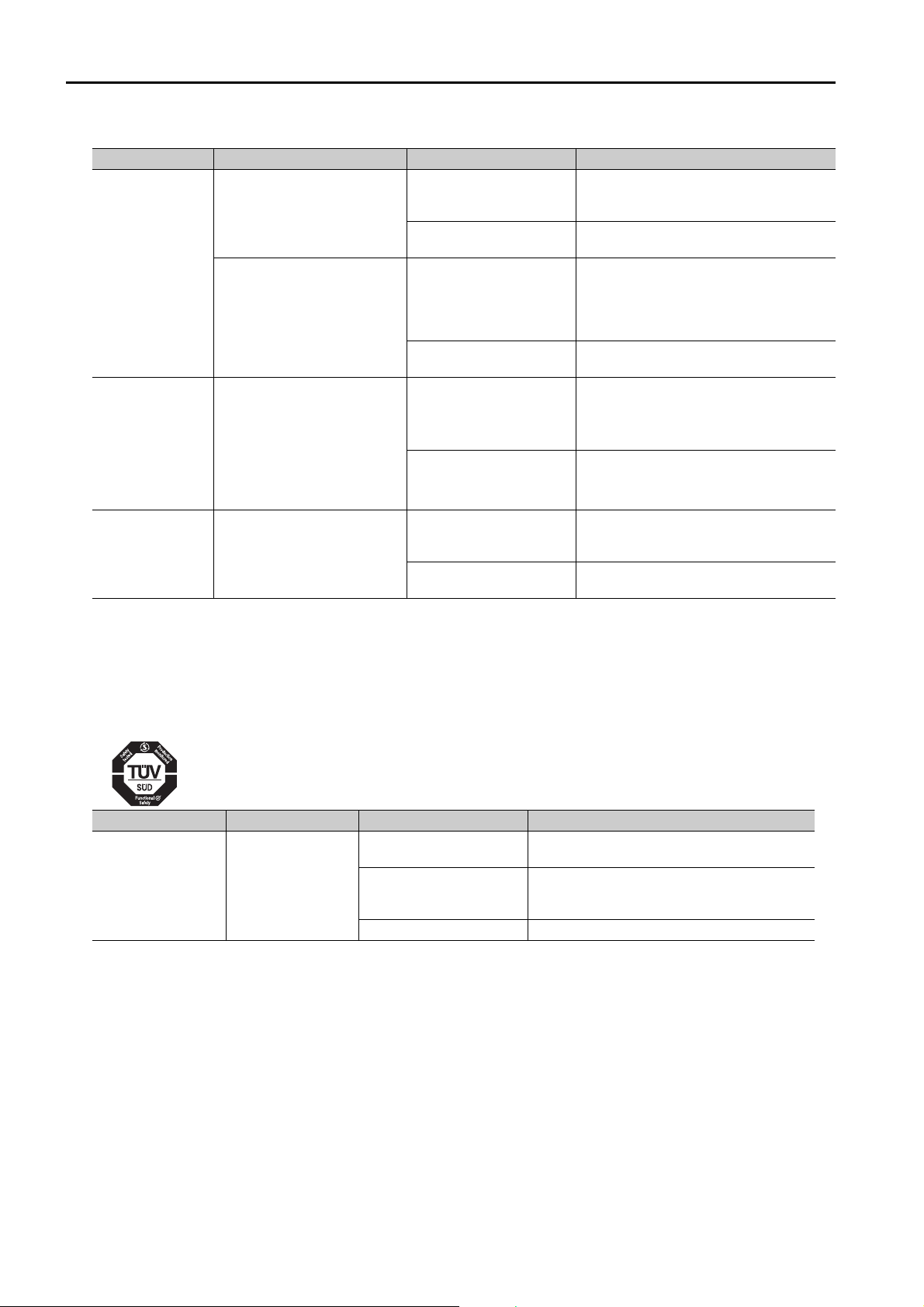
Compliance with UL Standards, EU Directives, and Other Safety Standards
S
Certification marks for the standards for which the product has been certified by certification bodies
are shown on nameplate. Products that do not have the marks are not certified for the standards.
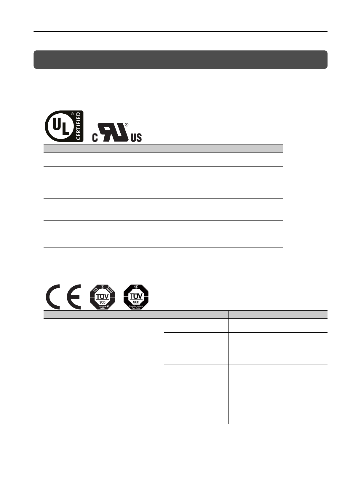
North American Safety Standards (UL)
Product Model North American Safety Standards (UL File No.)
SERVOPACKs
Rotary
Servomotors
Direct Drive
Servomotors
Linear
Servomotors
*1. Certification is pending.
*2. SGM7F-B, -C, and -D: Certified; SGM7F-A: Certification is pending.
*1
• SGD7S
• SGD7W
• SGMMV
• SGM7A
• SGM7J
• SGM7P
• SGM7G
• SGM7E
• SGM7F
• SGMCV
• SGLGW
• SGLFW
• SGLFW2
• SGLTW
*1
*2
*1
UL 61800-5-1 (E147823),
CSA C22.2 No.274
UL 1004-1
UL 1004-6
(E165827)
UL 1004-1
UL 1004-6
(E165827)
UL 1004
(E165827)
European Directives
Product Model European Directive Harmonized Standards
SERVOPACKs
SGD7S
SGD7W
Machinery Directive
2006/42/EC
EMC Directive
2014/30/EU
Low Voltage Directive
2014/35/EU
EMC Directive
2014/30/EU
Low Voltage Directive
2014/35/EU
EN ISO13849-1: 2015
EN 55011 group 1, class A
EN 61000-6-2
EN 61000-6-4
EN 61800-3
(Category C2, Second environment)
EN 50178
EN 61800-5-1
EN 55011 group 1, class A
EN 61000-6-2
EN 61000-6-4
EN 61800-3
(Category C2, Second environment)
EN 50178
EN 61800-5-1
Continued on next page.
xxvii
Page 28
S
Product Model European Directive Harmonized Standards
EMC Directive
SGMMV
2004/104/EC
Low Voltage Directive
2006/95/EC
Rotary
Servomotors
• SGM7J
• SGM7A
EMC Directive
2014/30/EU
• SGM7P
• SGM7G
Low Voltage Directive
2014/35/EU
• SGM7E
• SGM7F
• SGMCV
Direct Drive
Servomotors
• SGMCS-
(Small-Capacity, Coreless
Servomotors)
• SGLG
Linear
Servomotors
• SGLF
• SGLFW2
• SGLT
*1. Certification is pending.
*2. SGM7E: Certification is pending, SGMCS: No application has been made for certification.
Note: 1. We declared the CE Marking based on the harmonized standards in the above table.
2. These products are for industrial use. In home environments, these products may cause electromagnetic interference and additional noise reduction measures may be necessary.
*1
B, C,
D, E
EMC Directive
2004/108/EC
Low Voltage Directive
2006/95/EC
EMC Directive
2004/108/EC
Low Voltage Directive
2006/95/EC
Continued from previous page.
EN 55011 group 1, class A
EN 61000-6-2
EN 61800-3
EN 60034-1
EN 60034-5
EN 55011 group 1, class A
EN 61000-6-2
EN 61000-6-4
EN 61800-3
(Category C2, Second environment)
EN 60034-1
EN 60034-5
EN 55011 group 1, class A
EN 61000-6-2
EN 61000-6-4
EN 61800-3
*2
*2
EN 60034-1
EN 60034-5
EN 55011 group 1, class A
EN 61000-6-2
EN 61000-6-4
EN 60034-1
Safety Standards
Product Model Safety Standards Standards
EN ISO13849-1: 2015
IEC 60204-1
IEC 61508 series
IEC 62061
IEC 61800-5-2
SERVOPACKs SGD7S
Safety of Machinery
Functional Safety
EMC IEC 61326-3-1
xxviii
Page 29
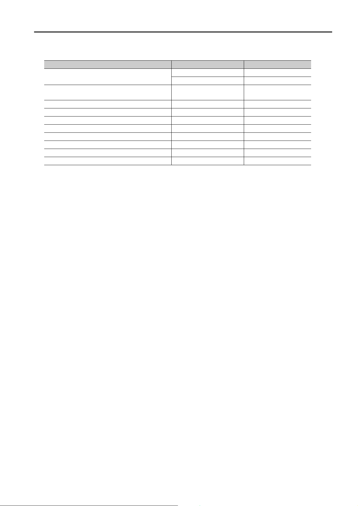
Safety Parameters
Item Standards Performance Level
Safety Integrity Level
Probability of Dangerous Failure per Hour
Performance Level EN ISO 13849-1 PLe (Category 3)
Mean Time to Dangerous Failure of Each Channel EN ISO 13849-1 MTTFd: High
Average Diagnostic Coverage EN ISO 13849-1 DCavg: Medium
Stop Category IEC 60204-1 Stop category 0
Safety Function IEC 61800-5-2 STO
Mission Time IEC 61508 10 years
Hardware Fault Tolerance IEC 61508 HFT = 1
Subsystem IEC 61508 B
IEC 61508 SIL3
IEC 62061 SILCL3
IEC 61508
IEC 62061
PFH = 4.04×10
(4.04% of SIL3)
-9
[1/h]
xxix
Page 30

1
Contents
About this Manual . . . . . . . . . . . . . . . . . . . . . . . . . . . . . . . . . . . . . . . . . . . . . . . . iii
Finding Information . . . . . . . . . . . . . . . . . . . . . . . . . . . . . . . . . . . . . . . . . . . . . . . iii
Related Documents . . . . . . . . . . . . . . . . . . . . . . . . . . . . . . . . . . . . . . . . . . . . . . . .v
Using This Manual . . . . . . . . . . . . . . . . . . . . . . . . . . . . . . . . . . . . . . . . . . . . . . . . xii
Safety Precautions . . . . . . . . . . . . . . . . . . . . . . . . . . . . . . . . . . . . . . . . . . . . . . . xv
Warranty . . . . . . . . . . . . . . . . . . . . . . . . . . . . . . . . . . . . . . . . . . . . . . . . . . . . . . xxv
Compliance with UL Standards, EU Directives, and Other Safety Standards. . xxvii
Basic Information on SERVOPACKs
2
1.1
1.2
1.3
1.4
About the Dynamic Brake Hardware Option Specifications . . . 1-2
1.1.1 What Is Dynamic Braking? . . . . . . . . . . . . . . . . . . . . . . . . . . . . . . . . . . . . . .1-2
1.1.2 Capabilities of SERVOPACKs That Support the Dynamic Brake Hardware
Option Specifications . . . . . . . . . . . . . . . . . . . . . . . . . . . . . . . . . . . . . . . . . .1-2
Interpreting the Nameplate . . . . . . . . . . . . . . . . . . . . . . . . . . . . 1-3
Part Names. . . . . . . . . . . . . . . . . . . . . . . . . . . . . . . . . . . . . . . . . 1-4
1.3.1 SGD7S-R70A to -2R8A, SGD7S-R70F to -2R8F, and SGD7W-1R6A
to -2R8A. . . . . . . . . . . . . . . . . . . . . . . . . . . . . . . . . . . . . . . . . . . . . . . . . . . .1-4
1.3.2 SGD7S-3R8A to -330A . . . . . . . . . . . . . . . . . . . . . . . . . . . . . . . . . . . . . . . . .1-4
1.3.3 SGD7S-470A to -780A . . . . . . . . . . . . . . . . . . . . . . . . . . . . . . . . . . . . . . . . .1-5
1.3.4 SGD7W-5R5A and -7R6A. . . . . . . . . . . . . . . . . . . . . . . . . . . . . . . . . . . . . . .1-5
Model Designations . . . . . . . . . . . . . . . . . . . . . . . . . . . . . . . . . . 1-6
1.4.1 Interpreting Σ-7S SERVOPACK Model Numbers . . . . . . . . . . . . . . . . . . . . . .1-6
1.4.2 Interpreting Σ-7W SERVOPACK Model Numbers . . . . . . . . . . . . . . . . . . . . .1-7
Selecting a SERVOPACK
2.1
Combinations of Servomotors and SERVOPACKs. . . . . . . . . . . 2-2
2.1.1 Combinations of Rotary Servomotors and SERVOPACKs . . . . . . . . . . . . . . .2-2
2.1.2 Combinations of Direct Drive Servomotors and SERVOPACKs . . . . . . . . . . .2-4
2.1.3 Combinations of Linear Servomotors and SERVOPACKs . . . . . . . . . . . . . . .2-6
xxx
3
2.2
External Dimensions . . . . . . . . . . . . . . . . . . . . . . . . . . . . . . . . . 2-8
Selecting a Dynamic Brake Resistor
3.1
3.2
3.3
Precautions . . . . . . . . . . . . . . . . . . . . . . . . . . . . . . . . . . . . . . . . 3-2
Selection Flow . . . . . . . . . . . . . . . . . . . . . . . . . . . . . . . . . . . . . . 3-3
Determining the Resistance of the Dynamic Brake Resistor . . . 3-4
3.3.1 How to Determine the Resistance of the Dynamic Brake Resistor . . . . . . . .3-4
3.3.2 Brake Torque and Dynamic Brake Resistance Characteristics . . . . . . . . . . .3-5
Page 31

4
5
3.4
3.5
Calculating the Energy Consumption of the Dynamic Brake Resistor . . 3-14
Presenting the Required Specifications to the Resistor Manufacturer . . 3-15
Wiring and Connecting a Dynamic Brake Resistor
4.1
4.2
Wiring and Connecting SERVOPACKs . . . . . . . . . . . . . . . . . . . . 4-2
Dynamic Brake Resistor Connections . . . . . . . . . . . . . . . . . . . . 4-5
4.2.1 Terminal Symbols and Terminal Names . . . . . . . . . . . . . . . . . . . . . . . . . . . . 4-5
4.2.2 Wire Sizes and Tightening Torques . . . . . . . . . . . . . . . . . . . . . . . . . . . . . . . 4-5
4.2.3 Crimp Terminals and Insulating Sleeves . . . . . . . . . . . . . . . . . . . . . . . . . . . 4-6
4.2.4 Dynamic Brake Resistor Connector Wiring Procedure. . . . . . . . . . . . . . . . . 4-8
4.2.5 Connecting Dynamic Brake Resistors . . . . . . . . . . . . . . . . . . . . . . . . . . . . . 4-9
Basic Functions That Require Setting before Operation
5.1
Outline . . . . . . . . . . . . . . . . . . . . . . . . . . . . . . . . . . . . . . . . . . . . 5-2
6
7
5.2
5.3
5.4
Motor Stopping Methods for Servo OFF and Alarms. . . . . . . . . 5-3
5.2.1 Stopping Method for Servo OFF . . . . . . . . . . . . . . . . . . . . . . . . . . . . . . . . . 5-4
5.2.2 Servomotor Stopping Method for Alarms . . . . . . . . . . . . . . . . . . . . . . . . . . 5-4
Motor Stopping Method for Overtravel . . . . . . . . . . . . . . . . . . . 5-6
Setting the Energy Consumption and Resistance of the Dynamic Brake Resistor . . 5-7
Maintenance
6.1
6.2
Alarms Related to the Dynamic Brake Hardware Option Specifications . . 6-2
6.1.1 List of Alarms . . . . . . . . . . . . . . . . . . . . . . . . . . . . . . . . . . . . . . . . . . . . . . . 6-2
6.1.2 Troubleshooting Alarms . . . . . . . . . . . . . . . . . . . . . . . . . . . . . . . . . . . . . . . . 6-3
Troubleshooting Based on the Operation and Conditions of the Servomotor . .6-6
Parameter Lists
7.1
Interpreting the Parameter Lists . . . . . . . . . . . . . . . . . . . . . . . . 7-2
7.2
List of Parameters . . . . . . . . . . . . . . . . . . . . . . . . . . . . . . . . . . . 7-3
xxxi
Page 32

Appendices
8
8.1
8.2
8.3
Monitor Displays for the Dynamic Brake Hardware Option Specifications . . 8-2
Coasting Distance when Stopping with the Dynamic Brake . . . 8-3
Data for Coasting Distance Calculation . . . . . . . . . . . . . . . . . . . 8-4
8.3.1 Coasting Distance Coefficients. . . . . . . . . . . . . . . . . . . . . . . . . . . . . . . . . . .8-4
8.3.2 Characteristic Impedance. . . . . . . . . . . . . . . . . . . . . . . . . . . . . . . . . . . . . . .8-6
Index
Revision History
xxxii
Page 33

Basic Information on SERVOPACKs
This chapter provides information required to select
SERVOPACKs, such as part names and SERVOPACK
models.
1
1.1
1.2
1.3
1.4 Model Designations . . . . . . . . . . . . . . . . . . . . . . . . . 1-6
About the Dynamic Brake Hardware Option Specifications . . 1-2
1.1.1 What Is Dynamic Braking? . . . . . . . . . . . . . . . . . 1-2
1.1.2 Capabilities of SERVOPACKs That Support
the Dynamic Brake Hardware Option
Specifications . . . . . . . . . . . . . . . . . . . . . . . . . . . 1-2
Interpreting the Nameplate . . . . . . . . . . . . . 1-3
Part Names . . . . . . . . . . . . . . . . . . . . . . . . . 1-4
1.3.1 SGD7S-R70A to -2R8A, SGD7S-R70F
to -2R8F, and SGD7W-1R6A to -2R8A . . . . . . . . 1-4
1.3.2 SGD7S-3R8A to -330A . . . . . . . . . . . . . . . . . . . . 1-4
1.3.3 SGD7S-470A to -780A . . . . . . . . . . . . . . . . . . . . 1-5
1.3.4 SGD7W-5R5A and -7R6A . . . . . . . . . . . . . . . . . . 1-5
1.4.1 Interpreting Σ-7S SERVOPACK Model
Numbers . . . . . . . . . . . . . . . . . . . . . . . . . . . . . . . 1-6
1.4.2 Interpreting Σ-7W SERVOPACK Model
Numbers . . . . . . . . . . . . . . . . . . . . . . . . . . . . . . . 1-7
Page 34

1.1 About the Dynamic Brake Hardware Option Specifications
CAUTION
1.1.1 What Is Dynamic Braking?
1.1
1.1.1
About the Dynamic Brake Hardware Option Specifications
Do not use the dynamic brake for any application other than an emergency stop.
There is a risk of failure due to rapid deterioration of elements in the SERVOPACK and the risk
of unexpected operation, machine damage, burning, or injury.
What Is Dynamic Braking?
If the servo turns OFF due to a loss of power or an emergency stop triggered by an alarm
during Servomotor operation, the SERVOPACK can no longer control the Servomotor. Therefore, the Servomotor will continue to coast when the servo is turned OFF until all of the kinetic
energy from its speed and moment of inertia is expended. Only an extremely small amount of
kinetic energy is expended when the servo is turned OFF. This results in an extremely long
coasting distance, which can damage the machinery or cause personal injury.
Dynamic braking uses a coasting Servomotor as a power generator to brake the Servomotor.
The Servomotor’s kinetic energy is converted to electrical energy and is expended as heat
through a resistor to stop the Servomotor.
1.1.2
Capabilities of SERVOPACKs That Support the Dynamic Brake Hardware Option Specifications
A SERVOPACK that supports the dynamic brake hardware option specifications does not have
a built-in dynamic brake resistor, and you can achieve the following things with it by using an
external dynamic brake resistor or by not connecting a resistor at all.
Note: Standard SERVOPACKs include a built-in dynamic brake. However, because the dynamic brake is built in, the
brake torque is fixed and there is a limit to the amount of kinetic energy that can be processed by the Servomotor.
Reduction of Brake Torque When Stopping with the Dynamic Brake
The brake torque can be adjusted according to the rigidity of the machine to prevent scattering
of conveyor objects caused by dynamic braking either by increasing the resistance of the
dynamic brake resistor or by not connecting the resistor at all.
Application to Equipment or Machines with a Higher Load Moment of
Inertia Than the Allowable Load Moment of Inertia in the Standard
Specifications
The dynamic brake can be applied to a machine with a high load moment of inertia by increasing the energy capacity of the dynamic brake resistor. If a dynamic brake resistor is not connected, dynamic braking can be disabled to allow the Servomotor to be turned by the machine.
The following specification is different for different SERVOPACK models.
1-2
SERVOPACK Model Specification
SGD7S-
SGD7W- 1R6A to 2R8A
SGD7S- 3R8A to 780A
SGD7W- 5R5A to 7R6A
R70A to 2R8A,
R70F to 2R8F
No dynamic brake
External dynamic brake resistor
Page 35

1.2 Interpreting the Nameplate
1
Basic Information on SERVOPACKs
1.2
Interpreting the Nameplate
The following basic information is provided on the nameplate.
SERVOPACK model
BTO information
Order number
Serial number
Degree of protection
Surrounding air temperature
1-3
Page 36

1.3 Part Names
1.3.1 SGD7S-R70A to -2R8A, SGD7S-R70F to -2R8F, and SGD7W-1R6A to -2R8A
1.3
1.3.1
1.3.2
Part Names
This section describes the connection terminals for an external dynamic brake resistor. All other
names are the same as those for a standard SERVOPACK. Refer to the standard SERVOPACK
product manual.
The external dynamic brake resistor terminals are used to connect an external dynamic brake
resistor. The terminal specifications and location depend on the SERVOPACK model. Refer to
the following section for the connection procedure.
4.2.5 Connecting Dynamic Brake Resistors on page 4-9
SGD7S-R70A to -2R8A, SGD7S-R70F to -2R8F, and
SGD7W-1R6A to -2R8A
These models do not support the dynamic brake hardware option specifications, so they do
not have external dynamic brake resistor terminals.
SGD7S-3R8A to -330A
The SGD7S-3R8A to -330A have external dynamic brake resistor terminals on the bottom of
the SERVOPACK.
1-4
Page 37

1.3 Part Names
1
Basic Information on SERVOPACKs
1.3.3 SGD7S-470A to -780A
1.3.3
SGD7S-470A to -780A
The SGD7S-470A to -780A have external dynamic brake resistor terminals on the front of the
SERVOPACK next to the CHARGE indicator.
• SGD7S-470A and -550A • SGD7S-590A and -780A
1.3.4
SGD7W-5R5A and -7R6A
The SGD7W-5R5A and -7R6A have external dynamic brake resistor terminals on the bottom of
the SERVOPACK.
1-5
Page 38

1.4 Model Designations
1.4.1 Interpreting Σ-7S SERVOPACK Model Numbers
1.4
1.4.1
Model Designations
Interpreting Σ-7S SERVOPACK Model Numbers
-
SGD7S
Σ-7-Series
Σ-7S
SERVOPACKs
1st+2nd+3rd digits
Voltage Code Specication
ThreePhase,
200 VAC
SinglePhase,
100 VAC
*1. You can use these models with either a single-phase or three-phase input.
*2. The same SERVOPACKs are used for both Rotary Servomotors and Linear Servomotors.
*3. The BTO specification indicates if the SERVOPACK is customized by using the MechatroCloud BTO service.
This service is available on the e-mechatronics website. You need a BTO number to order SERVOPACKs with
customized specifications. Refer to the following catalog for details.
*1
R70
*1
R90
*1
1R6
*1
2R8
3R8
*1
5R5
7R6
120
180
200
330
470
550
590
780
R70
R90
2R1
2R8
AC Servo Drives Σ-7 Series (Manual No.: KAEP S800001 23)
R70
1st+2nd+3rd
digits
Maximum Applicable
Motor Capacity
0.05 kW
0.1 kW
0.2 kW
0.4 kW
0.5 kW
0.75 kW
1.0 kW
1.5 kW
2.0 kW
3.0 kW
5.0 kW
6.0 kW
7.5 kW
11 kW
15 kW
0.05 kW
0.1 kW
0.2 kW
0.4 kW
A 00 A
4th
digit
4th digit
Code Specication
5th+6th digits
Code Specication
7th digit
5th+6th
digits
Voltage
A
200 VAC
F
100 VAC
Analog voltage/pulse train references
00
MECHATROLINK-II communications references
10
MECHATROLINK-III communications references
20
Command option attachable type
E0
Design Revision Order
A
Interface
7th
digit
*2
020
8th+9th+10th
digits
8th+9th+10th digits
Code
020
11th+12th+13th digits
002
Code
None
000
14th digit
Code
None
B
000
11th+12th+13th
digits
Specication
No dynamic brake SGD7S-R70A
External dynamic brake
resistor
Duct-ventilated
Varnished
Specification
None
BTO Specification
Specification
None
BTO specification
B
14th
digit
Hardware Options
Specication
to -2R8A
SGD7S-3R8A
to -780A
FT/EX Specification
*3
Applicable
Models
1-6
Page 39

1.4 Model Designations
1
Basic Information on SERVOPACKs
SGD7W
-
1R6
A 20 A
020
Σ-7-Series
Σ-7W
SERVOPACKs
4th
digit
1st+2nd+3rd
digits
5th+6th
digits
8th+9th+10th
digits
7th
digit
Maximum Applicable
Motor Capacity per Axis
A 200 VAC
Voltage
Code Specication
1R6
*1
2R8
*1
5R5
*1*2
7R6
0.2 kW
0.4 kW
0.75 kW
1.0 kW
Voltage Code Specication
ThreePhase,
200 VAC
1st+2nd+3rd digits
4th digit
8th+9th+10th digits
20
A
Interface
*3
Code Specication
MECHATROLINK-III
communications reference
Design Revision Order
5th+6th digits
7th digit
No dynamic brake SGD7W-1R6A
to -2R8A
SGD7W-5R5A
to -7R6A
020
External dynamic brake
resistor
Code
Specication
Applicable
Models
000
B
11th+12th+13th
digits
14th
digit
Hardware Options
Specication
Duct-ventilated
None
000
None
Specification
Code
FT/EX Specification
None
B
None
BTO specification
Specification
Code
BTO Specification
*4
11th+12th+13th digits
14th digit
1.4.2 Interpreting Σ-7W SERVOPACK Model Numbers
1.4.2
Interpreting Σ-7W SERVOPACK Model Numbers
*1. You can use these models with either a single-phase or three-phase input.
*2. If you use the Servomotor with a single-phase 200-VAC power supply input, derate the load ratio to 65%. An
*3. The same SERVOPACKs are used for both Rotary Servomotors and Linear Servomotors.
*4. The BTO specification indicates if the SERVOPACK is customized by using the MechatroCloud BTO service.
example is given below. If the load ratio of the first axis is 90%, use a load ratio of 40% for the second axis so
that average load ratio for both axes is 65%.
((90% + 40%)/2 = 65%)
This service is available on the e-mechatronics website. You need a BTO number to order SERVOPACKs with
customized specifications. Refer to the following catalog for details.
AC Servo Drives Σ-7 Series (Manual No.: KAEP S800001 23)
1-7
Page 40

Selecting a SERVOPACK
This chapter provides information required to select
SERVOPACKs, such as specifications and external dimensional drawings.
2.1 Combinations of Servomotors and SERVOPACKs . 2-2
2.1.1 Combinations of Rotary Servomotors and
SERVOPACKs . . . . . . . . . . . . . . . . . . . . . . . . . . . 2-2
2.1.2 Combinations of Direct Drive Servomotors and
SERVOPACKs . . . . . . . . . . . . . . . . . . . . . . . . . . . 2-4
2.1.3 Combinations of Linear Servomotors and
SERVOPACKs . . . . . . . . . . . . . . . . . . . . . . . . . . . 2-6
2
2.2
External Dimensions . . . . . . . . . . . . . . . . . . 2-8
Page 41

2.1 Combinations of Servomotors and SERVOPACKs
2.1.1 Combinations of Rotary Servomotors and SERVOPACKs
2.1
2.1.1
Combinations of Servomotors and SERVOPACKs
The maximum allowed load moment of inertia depends on the Servomotor and SERVOPACK
combination.
The maximum load moment of inertias listed here are determined by the durability of the dynamic
brake circuit, the regenerative processing circuit, and the Servomotor. Do not exceed the allow-
Important
Combinations of Rotary Servomotors and SERVOPACKs
SGMMV Models
(Low Inertia,
3,000 min
Models (Medium
Inertia, Small
3,000 min
(Low Inertia,
3,000 min
able load moment of inertia values given in the table when you select an external regenerative
resistor.
Allowable Load Moment of Inertia
[×10-4 kgm2]
J
L
L/JM
Hardware
Option
12.15 (25) 4.86 (10)
16 (20) 16 (20)
0.868 (40) 0.868 (40)
1.832 (40) 1.832 (40)
4.32 (20) 4.32 (20)
6.3 (20) 6.3 (20)
29.13 (30) 19.42 (20)
63.8 (20) 31.9 (10)
144 (15) 48 (5)
Servomotor Model
SGM7-
A1A 10 W 0.00272
Ultra-small
Capacity),
SGM7J
Capacity),
SGM7A
Models
Small
Capacity),
A2A 20 W 0.00466 0.1398 (30) 0.1398 (30)
A3A 30 W 0.00668 1R6A, 2R1F
-1
A5A 50 W 0.0395 R70A, R70F
01A 100 W 0.0659 R90A, R90F 2.3065 (35) 2.3065 (35)
C2A 150 W 0.0915
02A 200 W 0.263 6.575 (25) 3.945 (15)
04A 400 W 0.486 2R8A, 2R8F
-1
06A 600 W 0.8
08A 750 W 1.59 23.85 (15) 19.08 (12)
A5A 50 W 0.0217 R70A, R70F
01A 100 W 0.0337 R90A, R90F 1.348 (40) 1.348 (40)
C2A 150 W 0.0458
02A 200 W 0.139 4.17 (30) 4.17 (30)
04A 400 W 0.216 2R8A, 2R8F
06A 600 W 0.315
08A 750 W 0.775 23.25 (30) 15.5 (20)
10A 1.0 kW 0.971
15A 1.5 kW 2 40 (20) 20 (10)
-1
20A 2.0 kW 2.47 180A 49.4 (20) 24.7 (10)
25A 2.5 kW 3.19
30A 3.0 kW 7 105 (15) 35 (5)
40A 4.0 kW 9.6
50A 5.0 kW 12.3 184.5 (15) 61.5 (5)
70A 7.0 kW 12.3 550A 184.5 (15) 61.5 (5)
Capacity
Servomotor
Rotor
Moment of
Inertia J
M
-4
[×10
kgm2]
SERVOPACK Model
SGD7S- SGD7W-
R90A, R90F
1R6A, 2R1F
5R5A 5R5A, 7R6A
1R6A, 2R1F
5R5A 5R5A, 7R6A
120A
200A
330A
*1
1R6A
*1
2R8A
1R6A, 2R8A
*1
1R6A
*1
2R8A
1R6A, 2R8A
2R8A,
*1
5R5A
*1
7R6A
*1
1R6A
*1
2R8A
1R6A, 2R8A
2R8A,
*1
5R5A
*1
7R6A
−
The ratio J
SERVOPACKs
That Support the
Dynamic Brake
Specifications
0.0816 (30) 0.0816 (30)
,
*1
0.2004 (30) 0.2004 (30)
1.3825 (35) 1.3825 (35)
,
3.2025 (35) 3.2025 (35)
*1
,
,
*1
,
Continued on next page.
is given in paren-
theses.
Other
SERVOPACKs
2-2
Page 42

2.1 Combinations of Servomotors and SERVOPACKs
2
Selecting a SERVOPACK
2.1.1 Combinations of Rotary Servomotors and SERVOPACKs
Continued from previous page.
Allowable Load Moment of Inertia
[×10-4 kgm2]
J
L
is given in paren-
L/JM
theses.
Other
Hardware
SERVOPACKs
Option
1.48 (25) 1.48 (25)
3.945 (15) 3.945 (15)
37.2 (15) 37.2 (15)
199 (10) 99.5 (5)
322 (7) 138 (3)
Servomotor Model
SGM7-
Capacity
Servomotor
Rotor
Moment of
Inertia J
[×10
-4
kgm2]
M
SERVOPACK Model
SGD7S- SGD7W-
The ratio J
SERVOPACKs
That Support the
Dynamic Brake
Specifications
*1
,
1R6A
2R8A
5R5A
7R6A
*1
*1
,
*1
SGM7P
Models (Medium
Inertia, Flat),
3,000 min
-1
01A 100 W 0.0592 R90A, R90F
02A 200 W 0.263 2R8A, 2R1F 2R8A,
04A 400 W 0.409 2R8A, 2R8F 4.09 (10) 4.09 (10)
08A 750 W 2.1 5R5A 5R5A, 7R6A 10.5 (5) 10.5 (5)
15A 1.5 kW 4.02 120A − 20.1 (5) 20.1 (5)
03A 300 W 2.48
05A 450 W 3.33 49.95 (15) 49.95 (15)
3R8A
5R5A
7R6A
*1
,
*1
09A 850 W 13.9 7R6A 139 (10) 69.5 (5)
13A 1.3 kW 19.9 120A
SGM7G
Models (Medium
Inertia, Medium
Capacity),
1,500 min
20A 1.8 kW 26 180A 260 (10) 130 (5)
2.4 kW 46 200A 460 (10) 230 (5)
*2
30A
-1
44A 4.4 kW 67.5 675 (10) 337.5 (5)
2.9 kW 46
330A
−
55A 5.5 kW 89 470A 890 (10) 445 (5)
75A 7.5 kW 125 550A 1250 (10) 625 (5)
1AA 11 kW 242 590A 2420 (10) 1210 (5)
1EA 15 kW 303 780A 3030 (10) 1515 (5)
*1. If you use this combination, the control gain may not increase as much as with a Σ-7S SERVOPACK and other
performances may be lower than those achieved with a Σ-7S SERVOPACK.
*2. The capacity depends on the SERVOPACK that is used with the Servomotor.
2-3
Page 43

2.1 Combinations of Servomotors and SERVOPACKs
2.1.2 Combinations of Direct Drive Servomotors and SERVOPACKs
2.1.2
Combinations of Direct Drive Servomotors and SERVOPACKs
Allowable Load Moment of Iner-
tia J
[×10-4 kgm2]
L
is given in paren-
L/JM
theses.
Other
SERVOPACKs
280 (10) 280 (10)
770 (10) 770 (10)
2790 (3) 2790 (3)
Continued on next page.
Servomotor Model
SGM7D
(Outer Rotor with
Core)
SGM7E
(Small Capacity,
Coreless, Inner
Rotor)
SERVOPACK Model
Rated
Torq ue
[N·m]
30F 30.0 960
58F 58.0 1190 4165000 (3500) 178500 (150)
90F 90.0 1420 5680000 (4000) 213000 (150)
1AF 110 1670 8350000 (5000) 217100 (130)
01G 1.30 55.0
05G 5.00 75.0 22500 (300) 22500 (300)
08G 8.00 120
18G 18.0 150 450000 (3000) 52500 (350)
24G 24.0 190 760000 (4000) 57000 (300)
34G 34.0 230 920000 (4000) 57500 (250)
45G 45.0 270 1080000 (4000) 54000 (200)
03H 3.00 25.0 2R8A, 2R8F 15000 (600) 15000 (600)
28I 28.0 1800
70I 70.0 2000 4000000 (2000) 200000 (100)
1ZI 100 2300 5750000 (2500) 207000 (90)
1CI 130 2850 8550000 (3000) 228000 (80)
2BI 220 3400 34000 (100) 34000 (100)
2DI 240 4000 600000 (150) 600000 (150)
06J 6.00 150 105000 (700) 52500 (350)
09J 9.00 210 189000 (900) 52500 (250)
18J 18.0 240 600000 (2500) 57600 (240)
20J 20.0 260 520000 (2000) 57200 (220)
38J 38.0 330 660000 (2000) 59400 (180)
02K 2.06 60.0
06K 6.00 70.0 24500 (350) 24500 (350)
08K 8.00 80.0 2000 (25) 2000 (25)
06L 6.00 220 99000 (450) 99000 (450)
12L 12.0 220 4400 (20) 4400 (20)
30L 30.0 370 120A 1295000 (3500) 22200 (60)
02B 2 28.0
05B 5 51.0 510 (10) 510 (10)
07B 7 77.0 770 (10) 770 (10)
04C 4 77.0
10C 10 140 700 (5) 700 (5)
14C 14 220 660 (3) 660 (3)
08D 8 285 855 (3) 855 (3)
17D 17 510 1530 (3) 1530 (3)
25D 25 750 2250 (3) 2250 (3)
16E 16 930
35E 35 1430 4290 (3) 4290 (3)
Servomotor
Rotor Moment of
Inertia J
kgm
[×10-4
M
2
]
SGD7S- SGD7W-
120A
2R8A, 2R8F
120A
–
120A
2R8A, 2R8F
2R8A, 2R1F
2R8A
2R8A, 2R8F
5R5A
The ratio J
SERVOPACKs
That Support
the Dynamic
Brake Hardware Option
Specifications
2400000 (2500) 192000 (200)
7150 (130) 7150 (130)
240000 (2000) 48000 (400)
1440000 (800) 90000 (50)
12000 (200) 12000 (200)
2-4
Page 44

2.1 Combinations of Servomotors and SERVOPACKs
2
Selecting a SERVOPACK
2.1.2 Combinations of Direct Drive Servomotors and SERVOPACKs
Continued from previous page.
Allowable Load Moment of Iner-
[×10-4 kgm2]
tia J
SERVOPACK Model
Servomotor Model
02A 2 8.04
05A 5 14.5 507.5 (35) 507.5 (35)
07A 7 19.3
04B 4 16.2 405 (25) 405 (25)
SGM7F
(Small Capacity,
With Core, Inner
Rotor)
SGM7F
(Medium Capac-
ity, With Core,
Inner Rotor)
SGMCV
(Small Capacity,
With Core, Inner
Rotor)
SGMCS
(Small Capacity,
Coreless, Inner
Rotor)
SGMCS
(Medium Capac-
ity, With Core,
Inner Rotor)
* Use derated values for this combination. Refer to the following catalog for information on derating values.
AC Servo Drives Σ-7 Series (Catalog No.: KAEP S800001 23)
10B 10 25.2 1008 (40) 1008 (40)
14B 14 36.9 5R5A 1660.5 (45) 1660.5 (45)
08C 8 56.5 2R8A, 2R8F 2R8A 847.5 (15) 847.5 (15)
17C 17 78.5 5R5A 1962.5 (25) 1962.5 (25)
25C 25 111 7R6A 2775 (25) 2775 (25)
16D 16 178 5R5A 1780 (10) 1780 (10)
35D 35 276 7R6A*, 120A 7R6A* 4140 (15) 4140 (15)
45M 45 388 7R6A 1164 (3) 1164 (3)
80M 80 627
80N 80 865 2595 (3) 2595 (3)
1AM 110 1360 180A 4080 (3) 4080 (3)
1EN 150 2470
2ZN 200 3060 9180 (3) 9180 (3)
04B 4 16.2
10B 10 25.2 1008 (40) 1008 (40)
14B 14 36.9 5R5A 1660.5 (45) 1660.5 (45)
08C 8 56.5 2R8A 847.5 (15) 847.5 (15)
17C 17 78.5 5R5A 1962.5 (25) 1962.5 (25)
25C 25 111 7R6A 2775 (25) 2775 (25)
16D 16 178 5R5A 1780 (10) 1780 (10)
35D 35 276 7R6A*, 120A 7R6A* 4140 (15) 4140 (15)
02B 2 28
05B 5 51 510 (10) 510 (10)
07B 7 77 770 (10) 770 (10)
04C 4 77
10C 10 140 700 (5) 700 (5)
14C 14 220 660 (3) 660 (3)
08D 8 285 855 (3) 855 (3)
17D 17 510 1530 (3) 1530 (3)
25D 25 750 2250 (3) 2250 (3)
16E 16 930
35E 35 1430 4290 (3) 4290 (3)
45M 45 388 7R6A 1164 (3) 1164 (3)
80M 80 627
80N 80 865 2595 (3) 2595 (3)
1AM 110 1360 180A 4080 (3) 4080 (3)
1EN 150 2470
2ZN 200 3060 9180 (3) 9180 (3)
Rated
To rq ue
[N·m]
Servomotor
Rotor Moment of
Inertia J
kgm
[×10-4
M
2
]
SGD7S- SGD7W-
2R8A, 2R1F
2R8A
2R8A, 2R8F
120A
–
200A
2R8A
2R8A, 2R1F
2R8A
2R8A, 2R8F
5R5A
120A
−
200A
The ratio J
SERVOPACKs
That Support
the Dynamic
Brake Hardware Option
Specifications
675.5 (35) 675.5 (35)
L
L/JM
theses.
201 (25) 201 (25)
1881 (3) 1881 (3)
7410 (3) 7410 (3)
405 (25) 405 (25)
280 (10) 280 (10)
770 (10) 770 (10)
2790 (3) 2790 (3)
1881 (3) 1881 (3)
7410 (3) 7410 (3)
is given in paren-
Other
SERVOPACKs
2-5
Page 45

2.1 Combinations of Servomotors and SERVOPACKs
2.1.3 Combinations of Linear Servomotors and SERVOPACKs
2.1.3
Combinations of Linear Servomotors and SERVOPACKs
SERVOPACK Model Maximum Allowable Payload [kg]
−
−
−
SERVOPACKs
That Support
the Dynamic
Brake Hardware Option
Specifications
3.4 3.4
110 110
3.2 3.2
80 67
5.6 5.6
110 110
110 95
SERVOPACKs
Continued on next page.
Other
Servomotor Model
SGLG
(Coreless
Models), Used
with Standard-
Force Mag-
netic Way
SGLG
(Coreless
Models), Used
with High-
Force Mag-
netic Way
SGLF
(Models with
F-type Iron
Cores)
Rated
Force
[N]
SGLGW-30A050C 12.5 40
SGLGW-30A080C 25 80
SGLGW-40A140C 47 140 5.9 5.9
SGLGW-40A253C 93 280
SGLGW-40A365C 140 420
SGLGW-60A140C 70 220
SGLGW-60A253C 140 440
SGLGW-60A365C 210 660 5R5A 48 48
SGLGW-90A200C 325 1300 120A
SGLGW-90A370C 550 2200 180A 190 190
SGLGW-90A535C 750 3000 200A 260 260
SGLGW-40A140C 57 230
SGLGW-40A253C 114 460
SGLGW-40A365C 171 690 3R8A 5R5A 58 58
SGLGW-60A140C 85 360
SGLGW-60A253C 170 720 3R8A 5R5A 61 61
SGLGW-60A365C 255 1080 7R6A 91 91
SGLFW-20A090A 25 86
SGLFW-20A120A 40 125 4.8 4.8
SGLFW-35A120A 80 220 8.7 8.7
SGLFW-35A230A 160 440 3R8A 5R5A 29 29
SGLFW-50A200B 280 600 5R5A 40 33
SGLFW-50A380B
SGLFW-1ZA200B 82 66
SGLFW-1ZA380B 1120 2400 200A 160 78
SGLFW2-30A070A 45 135
SGLFW2-30A120A 90 270 11 9.4
SGLFW2-30A230A*
SGLFW2-45A200A 280 840 5R5A 64 58
SGLFW2-45A380A* 560
LFW2-90A200A 560 1680 140 130
G
S
SGLFW2-90A380A 1120 3360 200A 290 160
SGLFW2-90A560A 1680 5040 330A 440 360
SGLFW2-1DA380A 1680 5040 200A 710 690
SGLFW2-1DA560A 2520 7560 330A 1000 1000
560 1200 120A
180 540 3R8A − 34 34
170 500
Instanta-
neous Maxi-
mum Force
[N]
1680 180A
1500
SGD7S- SGD7W-
R70A,
R70F
R90A,
R90F
1R6A,
2R1F
2R8A,
2R8F
1R6A,
2R1F
2R8A,
2R8F
1R6A,
2R1F
2R8A,
2R8F
1R6A,
2R1F
1R6A,
2R1F
1R6A,
2R1F
2R8A,
2R8F
120A
1R6A 1.7 1.7
1R6A
1R6A 12 12
2R8A 18 18
1R6A 9.9 9.9
2R8A 19 19
1R6A 12 12
2R8A 24 24
1R6A 18 18
1R6A
1R6A
2R8A 20 10
2-6
Page 46

2.1 Combinations of Servomotors and SERVOPACKs
2
Selecting a SERVOPACK
2.1.3 Combinations of Linear Servomotors and SERVOPACKs
SERVOPACK Model Maximum Allowable Payload [kg]
Rated
Servomotor Model
SGLTW-20A170A 130 380 3R8A 5R5A 25 25
SGLTW-20A320A 250 760 7R6A 50 50
SGLTW-20A460A 380 1140 120A − 76 76
SGLTW-35A170A 220 660
SGLTW-35A170H 300 600 40 33
SGLT
(Models with
T- t y pe Ir on
Cores)
* The force depends on the SERVOPACK that is used with the Servomotor.
SGLTW-35A320A 440 1320
SGLTW-35A320H 600 1200 82 67
SGLTW-35A460A 670 2000
SGLTW-40A400B 670 2600 280 280
SGLTW-40A600B 1000 4000 330A − 440 440
SGLTW-50A170H 450 900 5R5A 95 92
SGLTW-50A320H 900 1800 120A
SGLTW-80A400B 1300 5000 330A 690 690
SGLTW-80A600B 2000 7500 550A 1000 1000
Force
[N]
Instanta-
neous Maxi-
mum Force
[N]
SGD7S- SGD7W-
5R5A
120A
180A
Continued from previous page.
SERVOPACKs
That Support
the Dynamic
Brake Hardware Option
Specifications
44 44
88 88
−
−
130 130
190 190
Other
SERVOPACKs
2-7
Page 47

2.2 External Dimensions
Two sets of terminals
160
168
8
Ground
terminals
2 × M4
40
170
18
(4)
(75)
20±0.5 (mounting pitch)
168
160±0.5 (mounting pitch)
5
2×M4
Exterior
Mounting Hole Diagram
40
5
Unit: mm
Approx. mass: 1.0 kg
2.2
External Dimensions
All SERVOPACKs that support the dynamic brake hardware option specifications are basemounted. The external dimensions are the same for all interfaces.
•
Three-Phase, 200 VAC: SGD7S-R70A, -R90A, and -1R6A
Note: There are no dynamic brake resistor terminals.
5
168
Ground
terminals
2 × M4
160
8
Two sets of terminals
40
(75)
18
140
(4)
168
160 ±0.5 (mounting pitch)
Mounting Hole Diagram
• Three-Phase, 200 VAC: SGD7S-2R8A; Single-Phase, 100 VAC: SGD7S-R70F, -R90F, and
-2R1F
Note: There are no dynamic brake resistor terminals.
2×M4
Exterior
25
10 ±0.5 (mounting pitch)
40
Approx. mass: 0.8 kg
Unit: mm
2-8
Page 48

2.2 External Dimensions
2
Selecting a SERVOPACK
Two sets of
terminals
Ground
terminals
2 × M4
160
168
70
(75)
180
15
18
(4)
(25)
Dynamic brake resistor terminals
Unit: mm
Approx. mass: 1.6 kg
3×M4
168
160±0.5
(mounting pitch)
5
Exterior
70
6
58±0.5
(mounting pitch)
Mounting Hole Diagram
Dynamic brake resistor terminals
Two sets of
terminals
Ground
terminals
2 × M4
160
168
90
(75)
180
15
18
(4)
(25)
Unit: mm
Approx. mass: 1.6 kg
3×M4
168
160±0.5
(mounting pitch)
80±0.5
(mounting pitch)
Exterior
5
90
12.5
Mounting Hole Diagram
5
•
Three-Phase, 200 VAC: SGD7S-3R8A, -5R5A, and -7R6A; Single-Phase, 100 VAC: SGD7S-2R8F
•
Three-Phase, 200 VAC: SGD7S-120A
2-9
Page 49

2.2 External Dimensions
(24)
(110°)
100
180
188
(75)
180
14
(4)
3×M4
188
12.5
100
5
Unit: mm
Approx. mass: 2.7 kg
Dynamic brake resistor terminals
Ground
terminals
2 × M4
180±0.5
(mounting pitch)
82.5±0.5
(mounting pitch)
75±0.5
(mounting pitch)
Exterior
Mounting Hole Diagram
(110°)
(30)
250
258
110
(75)
210
(5)
14
4×M5
258
13
5
110
6
Unit: mm
Approx. mass: 4.4 kg
Dynamic brake resistor terminals
Ground
terminals
2 × M4
250±0.5
(mounting pitch)
100±0.5
(mounting pitch)
84±0.5
(mounting pitch)
Exterior
Mounting Hole Diagram
•
Three-Phase, 200 VAC: SGD7S-180A and -200A
• Three-Phase, 200 VAC: SGD7S-330A
2-10
Page 50

2
Selecting a SERVOPACK
•
Unit: mm
Approx. mass: 15.5 kg
Dynamic brake
resistor terminals
2 × M4
Ground
terminals
2 × M6
Terminals
8 × M6
Terminals
4 × M6
260
390
(75)
210
200±0.5
(mounting pitch)
30
260
Mounting Hole Diagram
390
375±0.5 (mounting pitch)
Exterior
4×M6
7.5
Three-Phase, 200 VAC: SGD7S-470A and -550A
315
2.2 External Dimensions
4×M6
6
Exterior
315
Terminals
4 × M5
Terminals
8 × M5
Ground
terminals
2 × M5
•
Three-Phase, 200 VAC: SGD7S-590A and -780A
170
Dynamic brake
resistor terminals
2 × M4
(75)
210
302.5±0.5 (mounting pitch)
14
142±0.5
(mounting pitch)
170
Mounting Hole Diagram
Approx. mass: 8.2 kg
Unit: mm
• Three-Phase, 200 VAC: SGD7W-1R6A and -2R8A
Note: There are no dynamic brake resistor terminals.
168
160
Two sets of terminals
8
Ground
terminals
3 × M4
70
18
(75) 180
3×M4
5
Exterior
168
0.5 (mounting pitch)
±
160
(4)
60±0.5
5
(mounting pitch)
65
70
Mounting Hole Diagram
Approx. mass: 1.6 kg
Unit: mm
2-11
Page 51

2.2 External Dimensions
Unit: mm
Approx. mass: 2.3 kg
Dynamic brake resistor terminals (2 sets)
Ground
terminals
3 × M4
Two sets of terminals
160
168
(76)
180
100 17 (4)(26)
14
100
5
90±0.5
(mounting pitch)
Mounting Hole Diagram
3×M4
5
Exterior
168
160±0.5
(mounting pitch)
• Three-Phase, 200 VAC: SGD7W-5R5A and -7R6A
2-12
Page 52

Selecting a Dynamic Brake Resistor
This chapter describes the flow and selection methods
used to select an external dynamic brake resistor.
3
3.1
3.2
3.3
3.4
3.5
Precautions . . . . . . . . . . . . . . . . . . . . . . . . . 3-2
Selection Flow . . . . . . . . . . . . . . . . . . . . . . . 3-3
Determining the Resistance of the Dynamic Brake Resistor . . 3-4
3.3.1 How to Determine the Resistance of the Dynamic
Brake Resistor . . . . . . . . . . . . . . . . . . . . . . . . . . 3-4
3.3.2 Brake Torque and Dynamic Brake Resistance
Characteristics . . . . . . . . . . . . . . . . . . . . . . . . . . 3-5
Calculating the Energy Consumption of the Dynamic Brake Resistor . .3-14
Presenting the Required Specifications to the Resistor Manufacturer . . 3-15
Page 53

3.1 Precautions
WARNING
CAUTION
3.1
Precautions
Use an external dynamic brake resistor that matches the specifications for the relevant
equipment or machine. Always evaluate the dynamic brake operation on the actual equipment or machine to confirm that there are no problems with the coasting distance or durability of the dynamic brake resistor. If necessary, select another dynamic brake resistor and
install any necessary safety devices in the machine.
There is a risk of unexpected operation, machine damage, burning, or injury when an emergency stop is performed.
The dynamic brake resistor cannot be used if the motor is turned by the machine after stop-
ping due to a power interruption or error. Coast the motor to a stop instead.
Failure to do so may cause the dynamic brake resistor or SERVOPACK to burn or may cause
injury.
Do not use the dynamic brake for any application other than an emergency stop.
There is a risk of failure due to rapid deterioration of elements in the SERVOPACK and the risk
of unexpected operation, machine damage, burning, or injury.
3-2
Page 54

3.2 Selection Flow
3
Selecting a Dynamic Brake Resistor
This concludes the selection process.
1. Determine the resistance of the dynamic brake resistor.
3.3 Determining the Resistance of the Dynamic Brake Resistor on page 3-4
2. Calculate the energy consumption of the dynamic brake resistor.
3.4 Calculating the Energy Consumption of the Dynamic Brake Resistor on page 3-14
3. Present the required specifications to the resistor manufacturer.
3.5 Presenting the Required Specifications to the Resistor Manufacturer on page 3-15
3.2
Selection Flow
Follow these steps to select an appropriate external dynamic brake resistor.
Note: Refer to the following section for information on calculating the dynamic brake coasting distance.
8.1 Monitor Displays for the Dynamic Brake Hardware Option Specifications on page 8-2
3-3
Page 55

3.3 Determining the Resistance of the Dynamic Brake Resistor
WARNING
Important
Example
Instantaneous maximum
dynamic brake force [N]
Dynamic brake resistance [Ω]
5101520253035400
3000
0
500
1000
1500
2000
2500
SGLTW-80A600B
9 Ω
3.3.1 How to Determine the Resistance of the Dynamic Brake Resistor
3.3
3.3.1
Determining the Resistance of the Dynamic Brake Resistor
How to Determine the Resistance of the Dynamic Brake
Resistor
Refer to the Servomotor’s characteristic graph to determine the dynamic brake resistance that
will satisfy the restrictions to the instantaneous maximum brake torque of the equipment or
machine.
Refer to the following section for Servomotor characteristic graphs.
3.3.2 Brake Torque and Dynamic Brake Resistance Characteristics on page 3-5
Do not set the resistance of the dynamic brake resistor to a value less than the minimum
allowed resistance.
There is a risk of burning in the SERVOPACK or Servomotor, damage to the machine, or injury.
• Increasing the dynamic brake resistance will also increase the coasting distance proportionally.
• The SGD7S-R70A to -2R8A, SGD7S-R70F to -2R8F, and SGD7W-1R6A to -2R8A do not sup-
port a dynamic brake. For these SERVOPACKs, the brake torque is limited to the friction of the
Servomotor and the equipment or machine.
If the brake torque does not require reduction, set the resistance of the connected dynamic
brake resistor as shown in the following table.
Minimum Allowed
Ω
Ω
Ω
Ω
Ω
Ω
Ω
SGD7S-
SGD7W-
Model
R70A to 2R8A,
R70F to 2R8F
3R8A to 7R6A
120 A (three-phase input) 3.5
180A to 200A 3
330A 1.5
470A to 550A 1
590A to 780A 0.6
1R6A to 2R8A –
5R5A to 7R6A 6
Under the following conditions, the dynamic brake resistance would be 9 Ω.
• Linear Servomotor Model: SGLTW-80A600B
• Brake force limit: 2000 N
Dynamic Brake Resistance (±5%)
–
6
3-4
Page 56

3.3 Determining the Resistance of the Dynamic Brake Resistor
3
Selecting a Dynamic Brake Resistor
0.0
0.5
1.0
1.5
2.0
2.5
3.0
3.5
4.0
0 40 80 120 160 200 240
SGM7G-05A
SGM7G-03A
0 40 80 120 160 200 240
0
1
2
3
4
5
6
7
8
SGM7J-06A
SGM7P-08A
SGM7A-08A
SGM7J-08A
SGM7A-06A
0
2
4
6
8
10
12
0 20 40 60 80 100 120 140
SGM7A-10A
SGM7P-15A
SGM7G-13A
SGM7A-15A
0
5
10
15
20
25
0 20 40 60 80 100 120
SGM7G-30A
SGM7A-30A
SGM7A-25A
0
10
20
30
40
35
25
15
5
0102030405060
SGM7G-30A
SGM7A-50A
SGM7A-40A
0.0
0.5
1.0
1.5
2.0
2.5
3.0
3.5
4.0
0 40 80 120 160 200 240
SGM7J-04A
SGM7P-02A
SGM7P-04A
SGM7A-04A
0 40 80 120 160 200 240
0 20 40 60 80 100 120
0
1
2
3
4
5
6
7
0
2
4
6
8
10
12
14
SGM7G-20A
SGM7A-20A
SGM7G-09A
SGM7G-44A
Dynamic brake resistance [Ω]
SGD7S-3R8A, SGD7W-5R5A, 7R6A
Dynamic brake resistance [Ω]
SGD7S-5R5A, SGD7W-5R5A, 7R6A
Dynamic brake resistance [Ω]
SGD7-7R6A
Dynamic brake resistance [Ω]
SGD7S-120A
Dynamic brake resistance [Ω]
SGD7S-180A
Dynamic brake resistance [Ω]
SGD7S-200A
Dynamic brake resistance [Ω]
SGD7S-330A
Dynamic brake resistance [Ω]
SGD7W-5R5A, 7R6A
Instantaneous maximum
dynamic brake torque [Nm]
Instantaneous maximum
dynamic brake torque [Nm]
Instantaneous maximum
dynamic brake torque [Nm]
Instantaneous maximum
dynamic brake torque [Nm]
Instantaneous maximum
dynamic brake torque [Nm]
Instantaneous maximum
dynamic brake torque [Nm]
Instantaneous maximum
dynamic brake torque [Nm]
Instantaneous maximum
dynamic brake torque [Nm]
3.3.2 Brake Torque and Dynamic Brake Resistance Characteristics
3.3.2
Brake Torque and Dynamic Brake Resistance Characteristics
The following figures show the relationship between the instantaneous maximum dynamic
brake torque and dynamic brake resistance of the Servomotor.
For Rotary Servomotors
The following graphs show the Servomotors that can be used with each model of SERVOPACK.
3-5
Page 57

3.3 Determining the Resistance of the Dynamic Brake Resistor
0 5 10 15 20 25 30 35 40
0
10
20
30
40
50
60
70
80
90
SGM7G-75A
SGM7A-70A
0 4 8 12 16 20 24
0
20
40
60
80
100
120
140
SGM7G-1AA
0
20
40
60
80
100
120
140
160
180
0 4 8 12 16 20 24
SGM7G-1EA
0
10
20
30
40
50
60
0 5 10 15 20 25 30 35 40
SGM7G-55A
Dynamic brake resistance [Ω]Dynamic brake resistance [Ω]
Instantaneous maximum
dynamic brake torque [Nm]
Instantaneous maximum
dynamic brake torque [Nm]
Instantaneous maximum
dynamic brake torque [Nm]
Instantaneous maximum
dynamic brake torque [Nm]
SGD7S-550A
Dynamic brake resistance [Ω]
SGD7S-590A
Dynamic brake resistance [Ω]
SGD7S-780A
SGD7S-470A
3.3.2 Brake Torque and Dynamic Brake Resistance Characteristics
3-6
Page 58

3.3 Determining the Resistance of the Dynamic Brake Resistor
3
Selecting a Dynamic Brake Resistor
3.3.2 Brake Torque and Dynamic Brake Resistance Characteristics
For Direct Drive Servomotors
The following graphs show the Servomotors that can be used with each model of SERVOPACK.
SGD7-5R5A
40
35
30
25
20
15
10
Instantaneous maximum
5
dynamic brake torque [Nm]
0
0 40 80 120 160 200 240
180
160
140
120
100
80
60
40
Instantaneous maximum
20
dynamic brake torque [Nm]
0
0 40 80 120 160 200 240
SGMCV-16DA or
SGM7F-16D
Dynamic brake resistance [Ω]
SGMCS-35E
SGMCV-14BA or SGM7F-14BA
SGMCV-17CA or SGM7F-17CA
Dynamic brake resistance [Ω]
A
B or SGM7E-35EA
80
70
60
50
40
30
20
Instantaneous maximum
10
dynamic brake torque [Nm]
0
0 40 80 120 160 200 240
SGMCS-16EB or
SGM7E-16E
Dynamic brake resistance [Ω]
A
SGD7-7R6A
90
80
70
60
50
40
30
20
Instantaneous maximum
10
dynamic brake torque [Nm]
0
0 40 80 120 160 200 240
SGMCV-35DA or SGM7F-35DA
Dynamic brake resistance [Ω]
70
60
50
40
30
20
Instantaneous maximum
10
dynamic brake torque [Nm]
0
0 40 80 120 160 200 240
SGMCS-45MA or SGM7F-45MA
SGMCV-25CA or SGM7F-25CA
Dynamic brake resistance [Ω]
3-7
Page 59

3.3 Determining the Resistance of the Dynamic Brake Resistor
0
10
20
30
40
50
60
70
0
5
10
15
20
25
30
20
0
60
80
100
120
140
160
0
5
10
15
20
25
30
0
0
0
20
40
60
80
100
120
140
0 20 40 60 80 100 120 140
Dynamic brake resistance [Ω]
0 20 40 60 80 100 120 140
Dynamic brake resistance [Ω]
0 20 40 60 80 100 120 140
Dynamic brake resistance [Ω]
0 20 40 60 80 100 120 140
Dynamic brake resistance [Ω]
0 20 40 60 80 100 120 140
Dynamic brake resistance [Ω]
0 20 40 60 80 100 120 140
Dynamic brake resistance [Ω]
0 20 40 60 80 100 120 140
Dynamic brake resistance [Ω]
SGMCS-80NA or SGM7F-80NA
SGMCS-80MA or SGM7F-80MA
40
2
4
6
8
10
12
14
16
18
10
20
30
40
50
60
70
80
90
SGM7D-30FC
SGM7D-30LC
SGMCV-35DA or
SGM7F-35D
A
SGM7D-1AFC
SGM7D-90FC
SGM7D-58FC
SGM7D-18GC
SGM7D-08GC
SGM7D-45GC
SGM7D-34GC
SGM7D-24GC
SGM7D-09JC
SGM7D-06JC
SGM7D-38JC
SGM7D-20JC
SGM7D-18JC
SGM7D-1ZIC
SGM7D-70IC
SGM7D-28IC
SGM7D-2DIC
SGM7D-2BIC
SGM7D-1CIC
Instantaneous maximum
dynamic brake torque [Nm]
Instantaneous maximum
dynamic brake torque [Nm]
Instantaneous maximum
dynamic brake torque [Nm]
Instantaneous maximum
dynamic brake torque [Nm]
Instantaneous maximum
dynamic brake torque [Nm]
Instantaneous maximum
dynamic brake torque [Nm]
Instantaneous maximum
dynamic brake torque [Nm]
3.3.2 Brake Torque and Dynamic Brake Resistance Characteristics
SGD7S-120A
3-8
Page 60

3
Selecting a Dynamic Brake Resistor
0
50
100
150
200
250
0
50
100
150
200
250
300
350
400
450
0 20 40 60 80 100 120 0 20 40 60 80 100 120
Dynamic brake resistance [Ω] Dynamic brake resistance [Ω]
SGMCS-1AMA or SGM7F-1AMA
SGMCS-2ZNA or SGM7F-2ZNA
SGMCS-1ENA or SGM7F-1ENA
Instantaneous maximum
dynamic brake torque [Nm]
Instantaneous maximum
dynamic brake torque [Nm]
SGD7S-180A
3.3 Determining the Resistance of the Dynamic Brake Resistor
3.3.2 Brake Torque and Dynamic Brake Resistance Characteristics
3-9
Page 61

3.3 Determining the Resistance of the Dynamic Brake Resistor
0 40 80 120 160 200 240
04080
120
160 200 240
0
200
400
600
800
1000
0 40 80 120 160 200 240
0
50
100
150
200
250
300
350
0
40
80
120
160
SGLGW-60A253C*
SGLFW-35A230A
SGLFW2-30A230A
SGLGW-40A365C*
SGLTW-20A170A
Dynamic brake resistance [Ω]
Instantaneous maximum
dynamic brake force [N]
Dynamic brake resistance [Ω]
Dynamic brake resistance [Ω]
Instantaneous maximum
dynamic brake force [N]
Instantaneous maximum
dynamic brake force [N]
0
0
200
400
600
800
1000
40 80 120 160 200 240
SGLGW-60A365C
40 80 120 160 200 2400
0
50
100
150
200
250
300
40 80 120 160 200 2400
0
100
200
300
400
SGLTW-50A170H
SGLTW-35A170H
SGLTW-35A170A
SGLFW2-45A200A
SGLFW-50A200B
Dynamic brake resistance [Ω] Dynamic brake resistance [Ω]
Dynamic brake resistance [Ω]
Instantaneous maximum
dynamic brake force [N]
Instantaneous maximum
dynamic brake force [N]
Instantaneous maximum
dynamic brake force [N]
3.3.2 Brake Torque and Dynamic Brake Resistance Characteristics
For Linear Servomotors
The following graphs show the Servomotors that can be used with each model of SERVOPACK.
SGD7S-3R8A, SGD7W-2R8A, and SGD7W-5R5A
* These values are for combinations with High-Force Magnetic Ways.
SGD7-5R5A
3-10
Page 62

3.3 Determining the Resistance of the Dynamic Brake Resistor
3
Selecting a Dynamic Brake Resistor
0
200
400
600
800
1000
1200
0
50
100
150
200
250
300
350
SGLGW-60A365C*
0 40 80 120 160 200 240 0 40 80 120 160 200 240
SGLTW-20A320A
Dynamic brake resistance [Ω] Dynamic brake resistance [Ω]
Instantaneous maximum
dynamic brake force [N]
Instantaneous maximum
dynamic brake force [N]
0
40 80 120
0
400
800
1200
1600
SGLGW-90A200C
0
40 80 120
0
200
400
600
800
SGLTW-50A320H
SGLTW-35A320H
SGLTW-35A320A
SGLTW-20A460A
0
100
200
300
400
500
600
700
0
40 80 120
SGLFW2-90A200A
SGLFW2-45A380A
SGLFW-1ZA200B
SGLFW-50A380B
Dynamic brake resistance [Ω]
0
Dynamic brake resistance [Ω]
Dynamic brake resistance [Ω]
Instantaneous maximum
dynamic brake force [N]
Instantaneous maximum
dynamic brake force [N]
Instantaneous maximum
dynamic brake force [N]
3.3.2 Brake Torque and Dynamic Brake Resistance Characteristics
SGD7-7R6A
* These values are for combinations with High-Force Magnetic Ways.
SGD7S-120A
3-11
Page 63

3.3 Determining the Resistance of the Dynamic Brake Resistor
0
100
200
300
400
500
600
700
0
200
400
600
800
1000
0
20 40 60 80 100 120
0
20 40 60 80 100 120
0
20 40 60 80 100 120
0
500
1000
1500
2000
2500
SGLFW2-45A380A
SGLTW-40A400B
SGLTW-35A460A
SGLGW-90A370C
Dynamic brake resistance [Ω]
Dynamic brake resistance [Ω]
Dynamic brake resistance [Ω]
Instantaneous maximum
dynamic brake force [N]
Instantaneous maximum
dynamic brake force [N]
Instantaneous maximum
dynamic brake force [N]
0
500
1000
1500
2000
2500
3000
0
20 40 60 80 100 120
SGLGW-90A535C
0
400
800
1200
1600
2000
0 20 40 60 80 100 120
SGLFW2-1DA380A
SGLFW2-90A380A
SGLFW-1ZA380B
Dynamic brake resistance [Ω] Dynamic brake resistance [Ω]
Instantaneous maximum
dynamic brake force [N]
Instantaneous maximum
dynamic brake force [N]
01020 30405060
3000
0
500
1000
1500
2000
2500
SGLFW2-1DA560A
SGLFW2-90A560A
0
10 20 30 40 50 60
0
400
800
1200
1600
2000
SGLTW-80A400B
SGLTW-40A600B
Dynamic brake resistance [Ω]
Dynamic brake resistance [Ω]
Instantaneous maximum
dynamic brake force [N]
Instantaneous maximum
dynamic brake force [N]
3.3.2 Brake Torque and Dynamic Brake Resistance Characteristics
SGD7S-180A
3-12
SGD7S-200A
SGD7S-330A
Page 64

3
Selecting a Dynamic Brake Resistor
5101520253035400
3000
0
500
1000
1500
2000
2500
SGLTW-80A600B
Dynamic brake resistance [Ω]
Instantaneous maximum
dynamic brake force [N]
SGD7S-550A
3.3 Determining the Resistance of the Dynamic Brake Resistor
3.3.2 Brake Torque and Dynamic Brake Resistance Characteristics
3-13
Page 65

3.4 Calculating the Energy Consumption of the Dynamic Brake Resistor
EDB = ×
1
2
(m
M
+ mL) × v
2
3.4
Calculating the Energy Consumption of the Dynamic Brake Resistor
Calculate the energy that must be consumed by the resistance for one dynamic brake stop.
To simplify the energy consumption calculation, assume that all the kinetic energy until the Servomotor stops is consumed by the dynamic brake resistor and use the following formula.
Out of all possible operation patterns, use the one which maximizes the kinetic energy of the
Servomotor.
Rotary Servomotors
Energy consumption of the dynamic brake resistor: EDB [J]
Motor moment of inertia*: JM [kgm2]
Load inertia: J
Motor speed just before stopping with the dynamic brake: N [min
* For detailed information on the motor moment of inertia, refer to the catalog or Servomotor product manual.
Linear Servomotors
Energy consumption of the dynamic brake resistor: EDB [J]
Moving Coil mass*: m
Load mass: m
Motor speed just before stopping with the dynamic brake: v [m/s]
* For detailed information on Moving Coil mass, refer to the catalog or Servomotor product manual.
[kgm2]
L
[kg]
L
[kg]
M
1
EDB = ×
2
(J
+ JL) ×
M
-1
]
× N
2
)
2π
(
60
3-14
Page 66

3.5 Presenting the Required Specifications to the Resistor Manufacturer
3
Selecting a Dynamic Brake Resistor
Example
Resistor Energy
Consumption
Model Inquiries Manufacturer
1,000 J max. RH120 Series
Yaskawa Controls Co.,
Ltd.
Iwaki Musen Kenkyusho Co., Ltd.
2,000 J max. RH220 Series
10,000 J max. RH500 Series
3.5
Presenting the Required Specifications to the Resistor Manufacturer
Provide the following information to the manufacturer of your resistors and select a dynamic
brake resistor that is appropriate for the required specifications.
Required Information for Resistor Selection Reference
Resistance [Ω]
Resistor energy consumption for one operation of the
dynamic brake [J]
Number of dynamic brake operations (estimated number of
emergency stops required during the product life of your
system)
Wire sizes and crimped terminals
Note: The applicable wire sizes depend on the SERVOPACK
model.
Resistor Selection Example for a Dynamic Brake That Operates 1,000 Times
Refer to the following manual for the external dimensions of the dynamic brake resistor and
other parts in the selection example.
Σ
-7-Series Peripheral Device Selection Manual (Manual No.: SIEP S800001 32)
3.3 Determining the Resistance of the Dynamic
Brake Resistor on page 3-4
3.4 Calculating the Energy Consumption of the
Dynamic Brake Resistor on page 3-14
−
4.2.1 Terminal Symbols and Terminal Names on
page 4-5
4.2.2 Wire Sizes and Tightening Torques on
page 4-5
3-15
Page 67

Wiring and Connecting a Dynamic Brake Resistor
This chapter provides information required to wire and connect dynamic brake resistors.
4
4.1
4.2
Wiring and Connecting SERVOPACKs . . . . 4-2
Dynamic Brake Resistor Connections . . . . 4-5
4.2.1 Terminal Symbols and Terminal Names . . . . . . . . 4-5
4.2.2 Wire Sizes and Tightening Torques . . . . . . . . . . . 4-5
4.2.3 Crimp Terminals and Insulating Sleeves . . . . . . . 4-6
4.2.4 Dynamic Brake Resistor Connector Wiring
Procedure . . . . . . . . . . . . . . . . . . . . . . . . . . . . . . 4-8
4.2.5 Connecting Dynamic Brake Resistors . . . . . . . . . 4-9
Page 68

4.1 Wiring and Connecting SERVOPACKs
DANGER
WARNING
4.1
Wiring and Connecting SERVOPACKs
Do not change any wiring while power is being supplied.
There is a risk of electric shock or injury.
Wiring and inspections must be performed only by qualified engineers.
There is a risk of electric shock or product failure.
Check all wiring and power supplies carefully.
Incorrect wiring or incorrect voltage application to the output circuits may cause short-circuit failures. If a short-circuit failure occurs as a result of any of these causes, the holding brake will not
work. This could damage the machine or cause an accident that may result in death or injury.
Connect the AC and DC power supplies to the specified SERVOPACK terminals.
• Connect an AC power supply to the L1, L2, and L3 terminals and the L1C and L2C terminals on
the SERVOPACK.
• Connect a DC power supply to the B1/ and 2 terminals and the L1C and L2C terminals on
the SERVOPACK.
There is a risk of failure or fire.
If you use a SERVOPACK that supports the dynamic brake hardware option specifications,
connect an external dynamic brake resistor that is suitable for the machine and equipment
specifications to the specified terminals.
There is a risk of unexpected operation, machine damage, burning, or injury when an emergency stop is performed.
4-2
Page 69

4.1 Wiring and Connecting SERVOPACKs
4
Wiring and Connecting a Dynamic Brake Resistor
CAUTION
NOTICE
Wait for at least six minutes after turning OFF the power supply (with a SERVOPACK for a
100-VAC power supply input, wait for at least nine minutes) and then make sure that the
CHARGE indicator is not lit before starting wiring or inspection work. Do not touch the
power supply terminals while the CHARGE lamp is lit after turning OFF the power supply
because high voltage may still remain in the SERVOPACK.
There is a risk of electric shock.
Observe the precautions and instructions for wiring and trial operation precisely as
described in this document.
Failures caused by incorrect wiring or incorrect voltage application in the brake circuit may
cause the SERVOPACK to fail, damage the equipment, or cause an accident resulting in death
or injury.
Check the wiring to be sure it has been performed correctly.
Connectors and pin layouts are sometimes different for different models. Always confirm the
pin layouts in technical documents for your model before operation.
There is a risk of failure or malfunction.
Connect wires to power supply terminals and motor connection terminals securely with the
specified methods and tightening torque.
Insufficient tightening may cause wires and terminal blocks to generate heat due to faulty contact, possibly resulting in fire.
Use shielded twisted-pair cables or screened unshielded multi-twisted-pair cables for I/O
Signal Cables and Encoder Cables.
Observe the following precautions when wiring the SERVOPACK’s main circuit terminals.
• Turn ON the power supply to the SERVOPACK only after all wiring, including the main circuit terminals, has been completed.
• If a connector is used for the main circuit terminals, remove the main circuit connector from the
SERVOPACK before you wire it.
• Insert only one wire per insertion hole in the main circuit terminals.
• When you insert a wire, make sure that the conductor wire (e.g., whiskers) does not come into
contact with adjacent wires.
Install molded-case circuit breakers and other safety measures to provide protection
against short circuits in external wiring.
There is a risk of fire or failure.
Whenever possible, use the Cables specified by Yaskawa.
If you use any other cables, confirm the rated current and application environment of your
model and use the wiring materials specified by Yaskawa or equivalent materials.
Securely tighten cable connector screws and lock mechanisms.
Insufficient tightening may result in cable connectors falling off during operation.
Do not bundle power lines (e.g., the Main Circuit Cable) and low-current lines (e.g., the I/O
Signal Cables or Encoder Cables) together or run them through the same duct. If you do not
place power lines and low-current lines in separate ducts, separate them by at least 30 cm.
If the cables are too close to each other, malfunctions may occur due to noise affecting the lowcurrent lines.
Install a battery at either the host controller or on the Encoder Cable.
If you install batteries both at the host controller and on the Encoder Cable at the same time,
you will create a loop circuit between the batteries, resulting in a risk of damage or burning.
When connecting a battery, connect the polarity correctly.
There is a risk of battery rupture or encoder failure.
4-3
Page 70

4.1 Wiring and Connecting SERVOPACKs
Important
• Use a molded-case circuit breaker (1QF) or fuse to protect the main circuit. The SERVOPACK
connects directly to a commercial power supply; it is not isolated through a transformer or
other device. Always use a molded-case circuit breaker (1QF) or fuse to protect the servo system from accidents involving different power system voltages or other accidents.
• Install an earth leakage breaker. The SERVOPACK does not have a built-in ground fault protective circuit. To configure a safer system, install a ground fault detector against overloads and
short-circuiting, or install a ground fault detector combined with a molded-case circuit breaker.
• Do not turn the power supply ON and OFF more than necessary.
• Do not use the SERVOPACK for applications that require the power supply to turn ON and
OFF frequently. Such applications will cause elements in the SERVOPACK to deteriorate.
• After you have started actual operation, allow at least one hour between turning the power
supply ON and OFF (as a guideline).
To ensure safe, stable application of the servo system, observe the following precautions when
wiring.
• Use the cables specified by Yaskawa. Design and arrange the system so that each cable is
as short as possible.
Refer to the following manual for information on the specified cables.
Σ-7-Series Peripheral Device Selection Manual (Manual No.: SIEP S800001 32)
• The signal cable conductors are as thin as 0.2 mm2 or 0.3 mm2. Do not subject them to
excessive bending stress or tension.
4-4
Page 71

4.2 Dynamic Brake Resistor Connections
4
Wiring and Connecting a Dynamic Brake Resistor
CAUTION
4.2.1 Terminal Symbols and Terminal Names
4.2
4.2.1
Dynamic Brake Resistor Connections
Connectors or terminal blocks are used to wire a dynamic brake resistor.
The SGD7S-R70A to -2R8A, SGD7S-R70F to -2R8F, and SGD7W-1R6A to -2R8A do not support the dynamic brake hardware option specifications, so they do not have any dynamic brake
resistor terminals.
For the SGD7S-3R8A to -330A and SGD7W-5R5A to -7R6A, connect the external dynamic
brake resistor with the enclosed connectors.
For the SGD7S-470A to -780A, connect the external dynamic brake resistor using the terminal
block.
The location and dimensions depend on the model of the SERVOPACK. Refer to the following
sections for details.
1.3 Part Names on page 1-4
2.2 External Dimensions on page 2-8
For information on connections other than to the dynamic brake resistor terminals, refer to the
standard SERVOPACK product manual.
Termina l S ymbols a n d Termina l N a mes
Wire all connections correctly according to the following table.
If the wiring is not correct, there is a risk of SERVOPACK failure or fire.
SERVOPACK
Models
SGD7S- D1 and D2
SGD7W-
4.2.2
Wire Sizes and Tightening Torques
SERVOPACK Models
SGD7S-
SGD7W-
* Any wire sizes within the ranges given in this table can be used for the external dynamic brake resistor.
Ter mi na l
Symbols
D1A and
D2A
D1B and
D2B
R70A, R90A, 1R6A,
2R8A, R70F, R90F,
1R6F, and 2R8F
3R8A, 5R5A, 7R6A,
120A, 180A, 200A,
and 330A
470A and 550A D1 and D2
590A and 780A D1 and D2
1R6A and 2R8A - (There are no D1A, D2A, D1B, and D2B terminals.)
5R5A and 7R6A
Ter mi na l N am e Specification
Dynamic Brake
Resistor terminals
Dynamic Brake
Resistor terminals for axis
A
Dynamic Brake
Resistor terminals for axis
B
Ter mi na l
Symbols
- (There are no D1 and D2 terminals.)
D1 and D2
D1A, D2A,
D1B, and
D2B
AWG14 (2.0 mm2) to AWG18
(0.9 mm
AWG12 (3.5 mm
(0.9 mm
AWG12 (3.5 mm2) to AWG18
(0.9 mm
AWG14 (2.0 mm
(0.9 mm
These terminals are used to connect an external
dynamic brake resistor for a Σ-7S SERVOPACK.
Note: The SGD7S-R70A to -2R8A and -R70F to -2R8F
SERVOPACKs do not have D1 and D2 terminals.
These terminals are used to connect an external
dynamic brake resistor for a Σ-7W SERVOPACK.
Note: The SGD7W-1R6A to -2R8A SERVOPACKs do
not have D1A, D2A, D1B, and D2B terminals.
Wire Size
2
)*
2
2
)*
2
)*
2
)*
) to AWG18
2
) to AWG18
Screw
Size
––
M4 1.0 to 1.2
M4 1.6 to 1.8
––
Tightening
To rq ue
[Nm]
4-5
Page 72

4.2 Dynamic Brake Resistor Connections
4.2.3 Crimp Terminals and Insulating Sleeves
4.2.3
Crimp Terminals and Insulating Sleeves
For SGD7S-470A to -780A SERVOPACKs, use crimped terminals and insulating sleeves to
connect the dynamic brake resistor to the terminal block. Do not allow the crimp terminals to
come close to adjacent terminals or the case.
To comply with UL standards, you must use UL-compliant closed-loop crimp terminals and
insulating sleeves for the main circuit terminals. Use the tool recommended by the crimp terminal manufacturer to attach the crimp terminals.
The following tables give the recommended tightening torques, closed-loop crimp terminals,
and insulating sleeves in sets. Use the set that is suitable for your model and wire size.
If you use a SERVOPACK that supports the dynamic brake hardware option specifications and
connect an external dynamic brake resistor, refer to the following section.
SERVOPACK Models
470A and
550A
SGD7S-
590A and
780A
Screw
Size
M4
M4
Tighten-
ing
To rq ue
[Nm]]
1.0 to
1.2
1.6 to
1.8
Crimp Termi-
nal Horizon-
tal Width
9.9 mm max.
10.6 mm
max.
Recom-
mended Wire
Size
AWG12
(3.5 mm
AWG14
(2.0 mm
AWG16
(1.25 mm
AWG18
(0.9 mm
AWG12
(3.5 mm
AWG14
(2.0 mm
AWG16
(1.25 mm
AWG18
(0.9 mm
2
)
2
)
2
)
2
)
2
)
2
)
2
)
2
)
Crimp
Ter mi na l
Model
From J.S.T. Mfg.
5.5-S4
R2-4
R1.25-4
5.5-S4
R2-4
R1.25-4
Crimping
Tool
Co., Ltd.
YHT-2210
YHT-2210
Insulating
Sleeve
Model
From
Tok y o D i p
Co., Ltd.
TP-005
TP-003
TP-005
TP-003
4-6
Page 73

4.2 Dynamic Brake Resistor Connections
4
Wiring and Connecting a Dynamic Brake Resistor
L
F
E
d
2 dia.
B
d
1 dia.
D dia.
T
4.2.3 Crimp Terminals and Insulating Sleeves
Crimp Terminal Dimensional Drawing
Crimp Terminal Models: R1.25-4, R2-4, and 5.5-S4
Crimp
Ter mi na l
Model
R1.25-4
R2-4 8.5 16.8 7.8 4.1 2.3
d2 dia. B L F E D dia. d1 dia. T
8 15.8 7
4.3
Dimensions (mm)
4.8
3.4 1.7
0.8
5.5-S4 7.2 15.7 5.9 6.2 5.6 3.4 1.0
4-7
Page 74

4.2 Dynamic Brake Resistor Connections
Lock
Lock
4.2.4 Dynamic Brake Resistor Connector Wiring Procedure
4.2.4
Dynamic Brake Resistor Connector Wiring Procedure
• Required Items
Required Item Remarks
• Spring Opener
This is provided with the SERVOPACK. (It is attached to the dynamic brake resis-
Spring Opener or Flatblade Screwdriver
1.
Remove the dynamic brake resistor connector from the SERVOPACK. Press and hold
the lock with your finger, then pull out the connector.
tor connector.) The Spring Opener that is provided with the main circuit connector cannot be used.)
(You can also use a model J-FAT-OT Spring Opener from J.S.T. Mfg. Co., Ltd.)
• Flat-blade screwdriver
Commercially available screwdriver with tip width of 3.0 mm to 3.5 mm
2.
Remove the sheath from the wire to connect.
8 mm to 9 mm
3.
Open the wire insertion hole on the terminal connector with the tool. There are the following two ways to open the insertion hole. Use either method.
Using a Spring Opener
Press the Spring Opener in the direction of the
arrow to open the connector.
Spring Opener
Wire
4.
Insert the conductor into the wire insertion hole. Then, remove the Spring Opener or flat-
Using a Flat-blade Screwdriver
Firmly insert a flat-blade screwdriver into the
screwdriver insertion hole to open the wire insertion hole.
blade screwdriver.
4-8
5.
Make all other connections in the same way.
6.
When you have completed wiring, attach the connectors to the SERVOPACK.
Page 75

4.2 Dynamic Brake Resistor Connections
4
Wiring and Connecting a Dynamic Brake Resistor
WARNING
CAUTION
4.2.5 Connecting Dynamic Brake Resistors
4.2.5
Connecting Dynamic Brake Resistors
Wire dynamic brake resistors correctly. Do not connect the following terminals directly to
each other: D1 and D2, D1A and D2A, or D1B and D2B.
There is a risk of burning in the SERVOPACK or Servomotor, damage to the machine, or injury.
Mount dynamic brake resistors only on nonflammable materials. Do not mount them on or
near any flammable material.
There is a risk of fire.
SERVOPACK Models SGD7S-3R8A, -5R5A, -7R6A, -120A, -180A,
-200A, and -330A
1.
Connect the dynamic brake resistor to the D1 and D2 terminals on the SERVOPACK.
Note: 1. The D1 terminal is connector pin 1, and the D2 terminal is connector pin 3. Do not connect any-
thing to pin 2 (the center pin).
2. Terminal labels (D1 and D2) are provided on the dynamic brake resistor connector.
2.
Set Pn601 (Dynamic Brake Resistor Allowable Energy Consumption) and Pn604
(Dynamic Brake Resistance).
Refer to the following section for details on the settings.
5.4 Setting the Energy Consumption and Resistance of the Dynamic Brake Resistor on page 5-7
SERVOPACK Models SGD7S-470A, -550A, -590A, and -780A
1.
Connect the dynamic brake resistor to the D1 and D2 terminals on the SERVOPACK.
Note: Terminal labels (D1 and D2) are provided on the dynamic brake resistor connector.
2.
Set Pn601 (Dynamic Brake Resistor Allowable Energy Consumption) and Pn604
(Dynamic Brake Resistance).
Refer to the following section for details on the settings.
5.4 Setting the Energy Consumption and Resistance of the Dynamic Brake Resistor on page 5-7
4-9
Page 76

4.2 Dynamic Brake Resistor Connections
4.2.5 Connecting Dynamic Brake Resistors
SERVOPACK Models SGD7W-5R5A, and -7R6A
1.
Connect dynamic brake resistors to the D1A and D2A terminals and the D1B and D2B
terminals on the SERVOPACK.
Note: 1. The D1 terminal is connector pin 1, and the D2 terminal is connector pin 3. Do not connect
anything to pin 2 (the center pin).
2. Terminal labels (D1 and D2) are provided on the dynamic brake resistor connector.
2.
Set Pn601 (Dynamic Brake Resistor Allowable Energy Consumption) and Pn604
(Dynamic Brake Resistance) for each axis.
Refer to the following section for details on the settings.
5.4 Setting the Energy Consumption and Resistance of the Dynamic Brake Resistor on page 5-7
4-10
Page 77

Basic Functions That Require Setting before Operation
This chapter describes the setting methods for the following settings, which are some of the required settings before
operating the servo system: the dynamic brake resistances
and the stopping methods used when the servo is turned
OFF, when an alarm occurs, and when overtravel occurs.
5
5.1
5.2
5.3
5.4
Outline . . . . . . . . . . . . . . . . . . . . . . . . . . . . . 5-2
Motor Stopping Methods for Servo OFF and Alarms . . 5-3
5.2.1 Stopping Method for Servo OFF . . . . . . . . . . . . . 5-4
5.2.2 Servomotor Stopping Method for Alarms . . . . . . 5-4
Motor Stopping Method for Overtravel . . . . 5-6
Setting the Energy Consumption and Resistance of the Dynamic Brake Resistor . . 5-7
Page 78

5.1 Outline
5.1
Outline
This section describes the settings related to dynamic braking. These settings must be made
before operating a servo system. For information on basic functions not listed in the following
table, refer to the standard SERVOPACK product manual.
Function Reference
Stopping Method for Servo OFF
Servomotor Stopping Method for Alarms
Motor Stopping Method for Overtravel
Setting the Energy Consumption and
Resistance of the Dynamic Brake Resistor
5.2.1 Stopping Method for Servo OFF on page 5-4
5.2.2 Servomotor Stopping Method for Alarms on page 5-4
5.3 Motor Stopping Method for Overtravel on page 5-6
5.4 Setting the Energy Consumption and Resistance of the
Dynamic Brake Resistor on page 5-7
5-2
Page 79

5.2 Motor Stopping Methods for Servo OFF and Alarms
5
Basic Functions That Require Setting before Operation
Important
Condition
Servomotor Stopping Method
SGD7S-R70A,
-R90A, -1R6A,
-2R8A, -R70F,
-R90F, -2R1F,
and -2R8F, and
SGD7W-1R6A
and -2R8A
SGD7S-3R8A, -5R5A, -7R6A,
-120A, -180A, and -200A,
and SGD7W-5R5A and -7R6A
SGD7S-330A, -470A, -550A,
-590A, and -780A
External Dynamic Brake
Resistor
External Dynamic Brake
Resistor
Not connected Connected Not connected Connected
Main circuit
power supply
turned OFF
before turning
OFF the servo
Coasts to a
stop.
Coasts to a
stop.
Stops with the
dynamic brake.
Coasts to a
stop.
Stops with the
dynamic brake.
Control power
supply turned
OFF before
turning OFF
the servo
Coasts to a
stop.
5.2 Motor Stopping Methods for Servo OFF and Alarms
Set the parameters to specify the motor stopping methods to use when the servo is turned
OFF and when an alarm occurs. Refer to the following sections for details on settings.
5.2.1 Stopping Method for Servo OFF on page 5-4
5.2.2 Servomotor Stopping Method for Alarms on page 5-4
There are the following four stopping methods.
Motor Stopping Method Meaning
Stopping by Applying the
Dynamic Brake
Coasting to a Stop The motor stops naturally due to friction during operation.
Zero-Speed Stop The speed reference is set to 0 to stop the Servomotor quickly.
Decelerating to a Stop Emergency stop torque is used to decelerate the motor to a stop.
There are the following three conditions after stopping.
Status after Stopping Meaning
Dynamic Brake Applied The electric circuits are internally connected to hold the Servomotor.
Coasting
Zero Clamping
The electric circuits are internally connected to stop the Servomotor quickly.
The SERVOPACK does not control the Servomotor. (The machine will move in
response to a force from the load.)
A position loop is created and the Servomotor remains stopped at a position
reference of 0. (The current stop position is held.)
• The dynamic brake is used for emergency stops. The dynamic brake circuit will operate frequently if the power supply is turned ON and OFF or the servo is turned ON and OFF to start
and stop the Servomotor while a reference input is applied. This may result in deterioration of
the elements inside the SERVOPACK. Use speed input references or position references to
start and stop the Servomotor.
• To minimize the coasting distance of the Servomotor to come to a stop when an alarm occurs,
zero-speed stopping is the default method for alarms to which it is applicable. However,
depending on the application, stopping with the dynamic brake may be more suitable than
using a zero-speed stop.
For example, when coupling two shafts (twin-drive operation), machine damage may occur if a
zero-speed stopping alarm occurs for one of the coupled shafts and the other shaft stops with
a dynamic brake. In such cases, change the stopping method to the dynamic brake.
• If you turn OFF the main circuit power supply or control power supply during operation before
you turn OFF the servo for a SERVOPACK that supports the dynamic brake hardware option
specifications, the Servomotor stopping method depends on the SERVOPACK model as
shown in the following table.
5-3
Page 80

5.2 Motor Stopping Methods for Servo OFF and Alarms
5.2.1 Stopping Method for Servo OFF
5.2.1
Stopping Method for Servo OFF
Set the stopping method for when the servo is turned OFF in Pn001 = n.X (Servo OFF or
Alarm Group 1 Stopping Method).
To use the dynamic brake to stop the motor, set Pn001 to n.0 or n.1.
For a SERVOPACK that does not support a dynamic brake or for a SERVOPACK that supports
an external dynamic brake but to which an external dynamic brake resistor is not connected,
set Pn001 to n.2 (Coast the motor to a stop without the dynamic brake).
The default settings are different for different SERVOPACK models.
• SGD7S-R70A to -2R8A, SGD7S-R70F to -2R8F, and SGD7W-1R6A to -2R8A (no dynamic
brake): Pn001 = n.2
• SGD7S-3R8A to -780A and SGD7W-5R5A to -7R6A (external dynamic brake resistor):
Pn001 = n.0
Parameter
n.
0
Pn001
* If an external dynamic brake resistor is not connected, the Servomotor will coast to a stop.
Note: 1. If Pn001 is set to n.0 (Stop the motor by applying the dynamic brake) and the Servomotor is stopped
or operates at a low speed, braking force may not be generated, just like it is not generated for coasting to
a stop.
2. If Pn001 is set to n.0 (Stop the motor by applying the dynamic brake) when using an SGD7S-R70A
to -2R8A, SGD7S-R70F to -2R8F, or SGD7W-1R6A to -2R8A, an A.042 (Parameter Combination Error)
alarm will occur.
n.
1 Coasting
2 Coasting Coasting
Servomotor Stop-
ping Method
Dynamic brake*
Status after
Servomotor Stops
Dynamic brake*
When
Enabled
After restart Setupn.
Classifi-
cation
5.2.2
Servomotor Stopping Method for Alarms
There are two types of alarms, group 1 (Gr. 1) alarms and group 2 (Gr. 2) alarms. A different
parameter is used to set the stopping method for alarms for each alarm type.
To determine if the triggered alarm is Gr.1 or Gr.2, refer to the standard SERVOPACK product
manual.
Motor Stopping Method for Group 1 Alarms
When a group 1 alarm occurs, the Servomotor will stop according to the setting of Pn001 =
n.X. The default setting is to stop by applying the dynamic brake.
Refer to the following section for details.
5.2.1 Stopping Method for Servo OFF on page 5-4
Motor Stopping Method for Group 2 Alarms
When a group 2 alarm occurs, the Servomotor will stop according to the settings of the following three parameters. The default setting is for zero-speed stop.
• Pn001 = n.X (Servo OFF or Alarm Group 1 Stopping Method)
• Pn00A = n.X (Motor Stopping Method for Group 2 Alarms)
• Pn00B = n.X (Motor Stopping Method for Group 2 Alarms)
However, during torque control, the group 1 stopping method is always used.
If you set Pn00B to n.1 (Apply dynamic brake or coast Servomotor to a stop), you can
use the same stopping method as group 1. If you are coordinating a number of Servomotors,
you can use this stopping method to prevent machine damage that may result because of differences in the stopping method.
The following table shows the combinations of the parameter settings and the resulting stopping methods.
5-4
Page 81

5.2 Motor Stopping Methods for Servo OFF and Alarms
5
Basic Functions That Require Setting before Operation
5.2.2 Servomotor Stopping Method for Alarms
Parameter
Pn00B Pn00A Pn001
n.0
(default setting)
–
n.
n.
n.
n.
n.
1
–
n.
n.
n.
(default setting)
n.
0
n.
n.
n.
n.
1
n.
n.
2
n.
n.
n.
2
n.
n.
n.
3
n.
n.
n.
n.
4
n.
*1. The default settings are different for different SERVOPACK models.
• SGD7S-R70A to -2R8A, SGD7S-R70F to -2R8F, and SGD7W-1R6A to -2R8A (no dynamic brake): Pn001 =
2
n.
• SGD7S-3R8A to -780A and SGD7W-5R5A to -7R6A (external dynamic brake resistor): Pn001 = n.
*2. If an external dynamic brake resistor is not connected, the Servomotor will coast to a stop.
Note: 1. If Pn001 is set to n.0 (Stop the motor by applying the dynamic brake) when using an SGD7S-R70A
to -2R8A, SGD7S-R70F to -2R8F, or SGD7W-1R6A to -2R8A, an A.042 (Parameter Combination Error)
alarm will occur.
2. The setting of Pn00A is ignored if Pn001 is set to n.0 or n.1.
3. The setting of Pn00A = n.X is enabled for position control and speed control. During torque control,
the setting of Pn00A = n.X will be ignored and only the setting of Pn001 = n.X will be used.
4. For more information on Pn406 (Emergency Stop Torque), refer to the standard SERVOPACK product
manual.
5. For more information on Pn30A (Deceleration Time for Servo OFF and Forced Stops), refer to the standard
SERVOPACK product manual.
*1
0
1
2
0
1
2 Coasting
0
1
2 Coasting
0
1
2
0
1
2
0
1
2
0
1
2
Servomotor
Stopping Method
Zero-speed stopping
Dynamic brake
Dynamic brake
*2
*2
Motor is decelerated
using the torque set in
Pn406 as the maximum torque.
Motor is decelerated
according to setting
of Pn30A.
Status after
Servomo-
tor Stops
Dynamic
*2
brake
Coasting
Dynamic
*2
brake
Coasting
Dynamic
*2
brake
Coasting
Dynamic
*2
brake
Coasting
Coastingn.
Dynamic
*2
brake
Coasting
Coastingn.
When
Classifica-
Enabled
After restart Setup
0
tion
5-5
Page 82

5.3 Motor Stopping Method for Overtravel
5.3
Motor Stopping Method for Overtravel
You can set the stopping method of the Servomotor when overtravel occurs in Pn001 =
n.XX (Servo OFF or Alarm Group 1 Stopping Method and Overtravel Stopping Method).
The default settings are different for different SERVOPACK models.
• SGD7S-R70A to -2R8A, SGD7S-R70F to -2R8F, and SGD7W-1R6A to -2R8A (no dynamic
brake): Pn001 = n.
• SGD7S-3R8A to -780A and SGD7W-5R5A to -7R6A (external dynamic brake resistor):
Pn001 = n.
Pn001
*1. You cannot decelerate a Servomotor to a stop during torque control. For torque control, the Servomotor will be
stopped with the dynamic braking or coast to a stop (according to the setting of Pn001 = n.X (Servo OFF
or Alarm Group 1 Stopping Method)), and then the Servomotor will enter a coasting state.
*2. The Servomotor will coast to a stop if you use a SERVOPACK that does not support the dynamic brake hard-
ware option specifications (SGD7S-R70A to -2R8A, SGD7S-R70F to -2R8F, or SGD7W-1R6A to -2R8A) or do
not connect an external dynamic brake resistor.
*3. For detailed information on settings, refer to the standard SERVOPACK product manual.
Note: If Pn001 is set to n.0 (Stop the motor by applying the dynamic brake) when using an SGD7S-R70A to
-2R8A, SGD7S-R70F to -2R8F, or SGD7W-1R6A to -2R8A, an A.042 (Parameter Combination Error) alarm
will occur.
Parameter
n.
n.
n.
n.1
n.
2
n.3
n.
4
Refer to the standard SERVOPACK product manual for information on stopping methods other
than those for overtravel.
02
00
Motor Stop-
ping Method
00
01
02 Coasting
Dynamic brake
*2
Deceleration
according to
setting of
*3
Pn406
Deceleration
according to
setting of
*3
Pn30A
*1
Coasting
Zero clamp
Coasting
Zero clamp
Coasting
Status after
Stopping
When Enabled Classification
After restart Setup
5-6
Page 83

5.4 Setting the Energy Consumption and Resistance of the Dynamic Brake Resistor
5
Basic Functions That Require Setting before Operation
WARNING
CAUTION
Position
To rq ue
Position
To rq ue
5.4
Setting the Energy Consumption and Resistance of the Dynamic Brake Resistor
If an external dynamic brake resistor is connected, you must set Pn601 (Dynamic Brake Resistor Allowable Energy Consumption) and Pn604 (Dynamic Brake Resistance).
If you connect an external dynamic brake resistor, set Pn601 and Pn604 to suitable values.
Failure to set these parameters will cause A.730 (Dynamic Brake Overload) to be detected
incorrectly and can destroy the external dynamic brake resistor, cause unintended operation
during an emergency stop, cause damage to the machine, and cause burning or injury.
When you select an external dynamic brake resistor, make sure that it has a suitable energy
consumption and resistance.
There is a risk of personal injury or fire.
Mount dynamic brake resistors only on nonflammable materials. Do not mount them on or
near any flammable material.
There is a risk of fire.
Speed
Speed
Pn601
Pn604
Dynamic Brake Resistor Allowable Energy Consumption
Setting Range Setting Unit Default Setting When Enabled Classification
0 to 65,535 10 J 0 After restart Setup
Dynamic Brake Resistance
Setting Range Setting Unit Default Setting When Enabled Classification
0 to 65,535 10 m
Ω
0 After restart Setup
Set Pn601 to the energy consumption of the dynamic brake resistor that you calculated when
selecting the connected external dynamic brake resistor or the energy consumption of the
resistor as reported by the manufacturer.
Refer to the following section for details on the energy consumption of the dynamic brake resistor.
3.4 Calculating the Energy Consumption of the Dynamic Brake Resistor on page 3-14
Note: An A.042 alarm (Parameter Combination Error) will occur if Pn601 and Pn604 are not set on a SERVOPACK
that supports an external dynamic brake resistor (SGD7S-3R8A to -780A or SGD7W-5R5A to -7R6A).
5-7
Page 84

Maintenance
This chapter provides information on the meaning of,
causes of, and corrections for alarms related to the
dynamic brake hardware option specifications.
6
6.1
6.2
Alarms Related to the Dynamic Brake Hardware Option Specifications . . 6-2
6.1.1 List of Alarms . . . . . . . . . . . . . . . . . . . . . . . . . . . 6-2
6.1.2 Troubleshooting Alarms . . . . . . . . . . . . . . . . . . . . 6-3
Troubleshooting Based on the Operation and Conditions of the Servomotor . . 6-6
Page 85

6.1 Alarms Related to the Dynamic Brake Hardware Option Specifications
6.1.1 List of Alarms
6.1
6.1.1
Alarms Related to the Dynamic Brake Hardware Option Specifications
List of Alarms
This section gives the alarm names, alarm meanings, alarm stopping methods, alarm reset
possibilities, and alarm code outputs for alarms related to the dynamic brake hardware option
specifications.
Servomotor Stopping Method for Alarms
Refer to the standard SERVOPACK product manual for information on the motor stopping
method when an alarm occurs.
Alarm Reset Possibility
Yes: You can use an alarm reset to clear the alarm. However, this assumes that the cause of
the alarm has been removed.
No: You cannot clear the alarm.
List of Alarms
Alarm
Number
A.042
A.730 Dynamic Brake Overload
Parameter Combination
Error
Alarm Name Alarm Meaning
• The combination of some
parameters exceeds the
setting range.
• The required parameters
(Pn001, Pn601, and
Pn604) have not been set.
When the dynamic brake was
applied, the rotational or linear kinetic energy exceeded
the allowable energy consumption of the dynamic
brake resistor.
Servo-
motor
Stop-
ping
Method
Gr.1 No HHH
Gr.1 Yes L L L
Alarm
Reset
Possi-
ble?
Alarm Code
Output
ALO1 ALO2 ALO3
6-2
Page 86

6.1 Alarms Related to the Dynamic Brake Hardware Option Specifications
6
Maintenance
6.1.2 Troubleshooting Alarms
6.1.2
Troubleshooting Alarms
This section provides information on the causes of and corrections for alarms related to the
dynamic brake hardware option specifications. Contact your Yaskawa representative if you
cannot solve a problem with the corrections given in the table.
Alarm Number:
Alarm Name
A.042:
Parameter Combination Error
Possible Cause Confirmation Correction
The speed of program
jogging went below the
setting range when the
electronic gear ratio
(Pn20E/Pn210) or the
Servomotor was
changed.
The speed of program
jogging went below the
setting range when
Pn533 or Pn585 (Program Jogging Speed)
was changed.
The movement speed of
advanced autotuning
went below the setting
range when the electronic
gear ratio (Pn20E/ Pn210)
or the Servomotor was
changed.
Pn001 (Basic Function
Select Switch 1), Pn601
(Dynamic Brake Resistor
Allowable Energy Consumption), and Pn604
(Dynamic Brake Resistance) are not set correctly.
Check to see if the
detection conditions
are satisfied.
Check to see if the
detection conditions
are satisfied.
Check to see if the
detection conditions
are satisfied.
• Pn601 (Dynamic
Brake Resistor Allowable Energy Consumption) or Pn604
(Dynamic Brake
Resistance) is set to
0, even though using
the dynamic brake to
stop is specified in
the parameters
(Pn001 = n.0 or
Pn001 = n.1).
• Pn601 (Dynamic
Brake Resistor Allowable Energy Consumption) or Pn604
(Dynamic Brake
Resistance) is not set
to 0, even though
coasting the motor to
stop without using
the dynamic brake is
specified in the
parameters (Pn001 =
n.2).
Decrease the setting of
*1
the electronic gear ratio
(Pn20E/Pn210).
Increase the setting of
*1
Pn533 or Pn585.
Decrease the setting of
*2
the electronic gear ratio
(Pn20E/Pn210).
Set Pn001 (Basic Function Select Switch 1),
Pn601 (Dynamic Brake
Resistor Allowable Energy
Consumption), and Pn604
(Dynamic Brake Resistance) to the correct values.
Continued on next page.
Refer-
ence
–
–
–
page 7-3
6-3
Page 87

6.1 Alarms Related to the Dynamic Brake Hardware Option Specifications
6.1.2 Troubleshooting Alarms
Alarm Number:
Alarm Name
Possible Cause Confirmation Correction
The Servomotor was
rotated by an external
force.
Check the operation
status.
When the Servomotor
A.730:
was stopped by applying
the dynamic brake, the
rotational or linear kinetic
energy exceeded the
allowable energy consumption of the dynamic
brake resistor.
Use the monitor to
check the allowable
energy consumption of
the dynamic brake
resistor.
Dynamic Brake
Overload
(An excessive
power consumption by the
dynamic brake
was detected.)
The external dynamic
brake resistor is not connected properly.
Check the connection
status.
Check to confirm that
the allowable energy
consumption and
Pn601 (Dynamic Brake
Resistor Allowable Energy
Consumption) and Pn604
(Dynamic Brake Resistance) are not set correctly.
resistance of the con-
nected dynamic brake
resistor match the set-
tings of Pn601
(Dynamic Brake Resis-
tor Allowable Energy
Consumption) and
Pn604 (Dynamic Brake
Resistance).
A failure occurred in the
SERVOPACK.
–
Continued from previous page.
Implement measures to
ensure that the motor will
not be rotated by an
external force.
Reconsider the following:
• Reduce the Servomotor
command speed.
• Decrease the moment
of inertia ratio or mass
ratio.
• Reduce the frequency of
stopping with the
dynamic brake.
• Select a suitable external dynamic brake resistor.
Connect the selected
dynamic brake resistor
correctly.
Set Pn601 (Dynamic
Brake Resistor Allowable
Energy Consumption) and
Pn604 (Dynamic Brake
Resistance) to the correct
values.
The SERVOPACK may be
faulty. Replace the SERVOPACK.
Refer-
ence
–
–
–
page 7-3
–
6-4
Page 88

6.1 Alarms Related to the Dynamic Brake Hardware Option Specifications
6
Maintenance
Pn533 [min-1]
6 10
5
Pn20E
Pn210
Encoder resolution
Pn20E
Pn210
Maximum motor speed [min
-1
]
Encoder resolution
Approx. 3.66 10
12
Pn585 [mm/s]
10
Pn20E
Pn210
Pn385 [100 mm/s] Pn20E
Pn210
Linear encoder pitch [m]
Linear encoder pitch [m]
Resolution of Serial Converter Unit
Approx. 6.10 10
5
Resolution of Serial Converter Unit
1/3
610
5
Pn20E
Pn210
Rated motor speed [min
-1
]
Encoder resolution
*1. Detection Conditions
• Rotary Servomotor
If either of the following conditions is detected, an alarm will occur.
• Linear Servomotor
If either of the following conditions is detected, an alarm will occur.
*2. Detection Conditions
• Rotary Servomotor
If either of the following conditions is detected, an alarm will occur.
6.1.2 Troubleshooting Alarms
Maximum motor speed [min
・
Encoder resolution
-1
]
Approx. 3.66 10
Pn20E
12
Pn210
• Linear Servomotor
If either of the following conditions is detected, an alarm will occur.
Rated motor speed [mm/s] Resolution of Serial Converter Unit
Linear encoder pitch [m]
Pn385 [100 mm/s]
Linear encoder pitch [m]
1/3
Resolution of Serial Converter Unit
10
Approx. 6.10 10
5
Pn20E
Pn210
Pn20E
Pn210
6-5
Page 89

6.2 Troubleshooting Based on the Operation and Conditions of the Servomotor
6.2
Troubleshooting Based on the Operation and Conditions of the Servomotor
This section provides troubleshooting for problems related to the dynamic brake hardware
option specifications based on the operation and conditions of the Servomotor, including
causes and corrections.
Turn OFF the Servo System before troubleshooting the items shown in bold lines in the table.
Problem Possible Cause Confirmation Correction Reference
Dynamic Brake
Does Not
Operate
An External
Dynamic Brake
Resistor
Cannot Be
Connected
The setting of Pn001 =
n.X (Servo OFF or
Alarm Group 1 Stopping
Method) is not suitable.
Dynamic brake resistor is
disconnected.
The dynamic brake drive
circuit failure.
The external dynamic
brake resistor is not connected properly.
A SERVOPACK to which
an external dynamic
brake resistor cannot be
connected (SGD7SR70A to -2R8A or
SGD7W-1R6A to -2R8A)
is in use.
Check the setting of
Pn001 = n.X.
Check the moment of
inertia, motor speed, and
dynamic brake frequency
of use. The dynamic
brake resistor may be
disconnected if there
was excessive moment
of inertia, excessive
motor speed, excessive
use of the dynamic
brake, or if a suitable
external dynamic brake
has not been selected.
–
Check the connection
status.
Check the SERVOPACK
model.
Set Pn001 = n.X
correctly.
Replace the SERVOPACK. To prevent disconnection, reduce the
load.
A part in the dynamic
brake circuit has failed.
Replace the SERVOPAC K. Tak e m e asures to
reduce the load in order
to prevent damage to the
dynamic brake drive circuit.
Connect the selected
dynamic brake resistor
correctly.
Select another SERVOPAC K.
(Use a SERVOPACK that
accepts an externally
connected dynamic
brake resistor or a standard SERVOPACK.)
–
–
–
–
–
6-6
Page 90

Parameter Lists
This chapter provides information on parameters related to
the dynamic brake hardware option specifications.
7
7.1
7.2
Interpreting the Parameter Lists . . . . . . . . . 7-2
List of Parameters . . . . . . . . . . . . . . . . . . . . 7-3
Page 91

7.1 Interpreting the Parameter Lists
Differences in Terms for Rotary Servomotors and
Linear Servomotors on page xii
Indicates when a change to the
parameter will be effective.
n.X
Rotation Direction Selection
Reference
Movement Direction Selection
0
Use CCW as the forward direction.
page 5-24
Use the direction in which the linear encoder counts up as the forward direction.
1
Use CW as the forward direction. (Reverse Rotation Mode)
Use the direction in which the linear encoder counts down as the
forward direction. (Reverse Movement Mode)
n.X
Control Method Selection Reference
0 Speed control with analog references
page 5-15
1 Position control with pulse train references
2 Torque control with analog references
3 Internal set speed control with contact commands
4
Switching between internal set speed control with contact references and speed control with analog references
5
Switching between internal set speed control with contact references and position control with pulse train references
6
Switching between internal set speed control with contact references and torque control with analog references
7
Switching between position control with pulse train references and
speed control with analog references
8
Switching between position control with pulse train references and
torque control with analog references
9
Switching between torque control with analog references and
speed control with analog references
A
Switching between speed control with analog references and
speed control with zero clamping
B
Switching between position control with pulse train references and
position control with reference pulse inhibition
n.X Reserved parameter (Do not change.)
n.X
Rotary/Linear Servomotor Startup Selection When Encoder Is Not Connected
Reference
0
When an encoder is not connected, start as SERVOPACK for
Rotary Servomotor.
page 5-22
1
When an encoder is not connected, start as SERVOPACK for Linear Servomotor.
If there are differences in the parameters for Rotary
Servomotor and Linear Servomotor, information is
provided for both.
Bottom row: For Linear Servomotors
Top row: For Rotary Servomotors
7.1
Interpreting the Parameter Lists
The types of motors to which the parameter applies.
All: The parameter is used for both Rotary Servomotors and Linear Servomotors.
Rotary: The parameter is used for only Rotary Servomotors.
Linear: The parameter is used for only Linear Servomotors.
Rotary Servomotor terms are used for parameters that are applicable
to all Servomotors. If you are using a Linear Servomotor, you need to
interpret the terms accordingly. Refer to the following section for
details.
Parameter
No.
Size
2 Basic Function Selections 0
Name
Setting
Range
0000 to
10B1
Setting
Unit
Default
Setting
– 0000 All After restart Setup –
Applica-
ble Motors
There are the following two classications.
Setup
Tuning
For details, refer to the standard SERVOPACK
product manual.
When
Enabled
Classi-
fication
Refer-
ence
Pn000
7-2
Page 92

7.2 List of Parameters
7
Parameter Lists
n.X
Motor Stopping Method for Servo OFF and Group 1 Alarms Reference
0 Stop the motor by applying the dynamic brake.
–
1
Stop the motor by the applying dynamic brake and then release
the dynamic brake.
2 Coast the motor to a stop without the dynamic brake.
n.X
Overtravel Stopping Method Reference
0
Apply the dynamic brake or coast the motor to a stop (use the
stopping method set in Pn001 = n.X).
–
1
Decelerate the motor to a stop using the torque set in Pn406 as
the maximum torque and then servo-lock the motor.
2
Decelerate the motor to a stop using the torque set in Pn406 as
the maximum torque and then let the motor coast.
3
Decelerate the motor to a stop using the deceleration time set in
Pn30A and then servo-lock the motor.
4
Decelerate the motor to a stop using the deceleration time set in
Pn30A and then let the motor coast.
n.X Main Circuit Power Supply AC/DC Input Selection Reference
Refer to the standard SERVOPACK product manual.
n.X Warning Code Output Selection Reference
Refer to the standard SERVOPACK product manual.
7.2
List of Parameters
Parame-
ter No.
Pn001
Size
Application Function
2
Selections 1
Name
Setting
Range
0000 to
1142
Set-
ting
Unit
–
Default
Setting
000
*
Applica-
ble
Motors
All
When
Enabled
After
restart
Classi-
fica-
tion
Refer-
ence
Setup –
Pn601 2
Resistor Allowable
0 to 65,535 10 J 0 All
Energy Consumption
Dynamic Brake
Pn604 2
* The default settings are different for different SERVOPACK models.
• SGD7S-R70A to -2R8A, SGD7S-R70F to -2R8F, and SGD7W-1R6A to -2R8A (no dynamic brake): Pn001 =
n.0002
• SGD7S-3R8A to -780A and SGD7W-5R5A to -7R6A (external dynamic brake resistor): Pn001 = n.0000
Dynamic Brake
Resistance
0 to 65,535 10 mΩ 0All
After
restart
After
restart
Setup –
Setup –
7-3
Page 93

Appendices
The appendices provide information on monitor displays for
the dynamic brake hardware option specifications and
dynamic brake coasting distances.
8
8.1
8.2
8.3
Monitor Displays for the Dynamic Brake Hardware Option Specifications . . 8-2
Coasting Distance when Stopping with the Dynamic Brake . . 8-3
Data for Coasting Distance Calculation . . . 8-4
8.3.1 Coasting Distance Coefficients . . . . . . . . . . . . . . 8-4
8.3.2 Characteristic Impedance . . . . . . . . . . . . . . . . . . 8-6
Page 94

8.1 Monitor Displays for the Dynamic Brake Hardware Option Specifications
8.1
Monitor Displays for the Dynamic Brake Hardware Option Specifications
You can monitor the dynamic brake hardware option specifications with the SigmaWin+ or with
the Un numbers in the SERVOPACK.
SigmaWin+ SERVOPACK
Menu Bar
Button
Motion
Monitor
Function Name Fn No. Function Name
Energy consumption of the dynamic
brake resistor [%]
Un03B
Energy consumption of the dynamic brake resistor [%]
The percentage of the setting of Pn601 (Dynamic Brake
Resistor Allowable Energy Consumption) is displayed.
8-2
Page 95

8.2 Coasting Distance when Stopping with the Dynamic Brake
8
Appendices
WARNING
Lm = M
RD + Z
m
1
{
v
3
m0
}
[m]
(RD + Zm) v
m0
+
8.2
Coasting Distance when Stopping with the Dynamic Brake
When stopping with the dynamic brake, the motor continues to rotate due to inertia until the
motor’s energy has been completely expended.
The travel distance during this period is called the coasting distance.
The coasting distance must be confirmed on the actual equipment, but you can use the following formula to calculate an approximate value.
The calculated value of the coasting distance is a guideline. There may be error between the
calculated value and the actual coasting distance. Always evaluate the dynamic brake operation on the actual equipment or machine to confirm that there are no problems with the
coasting distance.
There is a risk of machine damage or injury.
For Rotary Servomotors
= J
{
(RD + Zm) N
m0
+
1
RD + Z
The above formula is based on the following conditions.
θ
[deg]: Coasting distance (mechanical angle)
•
2
• J [kgm
• R
• N
α, β
•
• Zm: Characteristic impedance
*1. Refer to the following section for details on the coasting distance coefficient.
*2. Refer to the following section for details on the characteristic impedance.
]: Moment of inertia (Motor moment of inertia + Load moment of inertia)
[Ω]: Selected dynamic brake resistance
D
[min-1]: Motor speed just before stopping with the dynamic brake
m0
: Coasting distance coefficients
*2
8.3.1 Coasting Distance Coefficients on page 8-4
8.3.2 Characteristic Impedance on page 8-6
3
m0
[deg]
}
N
m
*1
For Linear Servomotors
The above formula is based on the following conditions.
[m]: Coasting distance
• L
m
• M [kg]: Conveying weight (Moving Coil mass + Load weight)
[Ω]: Selected dynamic brake resistance
• R
D
[m/s]: Motor speed just before stopping with the dynamic brake
• V
m0
α, β
: Coasting distance coefficients
•
• Zm: Characteristic impedance
*1. Refer to the following section for details on the coasting distance coefficient.
8.3.1 Coasting Distance Coefficients on page 8-4
*2. Refer to the following section for details on the characteristic impedance.
8.3.2 Characteristic Impedance on page 8-6
*1
*2
8-3
Page 96

8.3 Data for Coasting Distance Calculation
8.3.1 Coasting Distance Coefficients
8.3
8.3.1
Data for Coasting Distance Calculation
This section provides information on the coasting distance coefficients and characteristic
impedance required to calculate the coasting distance.
Coasting Distance Coefficients
The following table shows the relationship between the Servomotor and coasting distance
coefficients α and β.
For Rotary Servomotors
Coasting Distance
Servomotor Model
SGM7J-06A 42.80 22.63 SGM7D-1ZI 0.02 572.13
SGM7J-08A 30.43 61.01 SGM7D-1CI 0.01 468.15
SGM7A-06A 50.09 148.56 SGM7D-2BI 0.01 465.81
SGM7A-08A 30.43 128.36 SGM7D-2DI 0.00 629.22
SGM7A-10A 35.45 41.19 SGM7D-06J 3.56 1875.52
SGM7A-15A 29.84 74.67 SGM7D-09J 0.96 1159.65
SGM7A-20A 32.96 34.33 SGM7D-18J 0.24 1466.78
SGM7A-25A 35.83 20.99 SGM7D-20J 0.11 923.57
SGM7A-30A 30.73 13.52 SGM7D-38J 0.06 1140.28
SGM7A-40A 38.65 8.15 SGM7D-30L 0.66 270.41
SGM7A-50A 28.44 6.54 SGM7E-16E 0.33 9.45
SGM7A-70A 28.44 6.54 SGM7E-35E 0.08 3.45
SGM7P-08A 45.95 93.14 SGM7F-14B 0.97 30.28
SGM7P-15A 33.30 31.97 SGM7F-17C 0.64 107.53
SGM7G-03A 17.24 494.99 SGM7F-25C 0.28 81.94
SGM7G-05A 14.26 237.63 SGM7F-16D 0.93 46.62
SGM7G-09A 14.07 87.07 SGM7F-35D 0.18 38.95
SGM7G-13A 13.09 36.01 SGM7F-45M 0.15 74.36
SGM7G-20A 18.59 14.82 SGM7F-80M 0.13 23.76
SGM7G-30A 14.45 5.76 SGM7F-80N 0.13 21.84
SGM7G-44A 11.91 2.80 SGM7F-1AM 0.15 7.86
SGM7G-55A 10.40 1.79 SGM7F-1EN 0.13 5.75
SGM7G-75A 11.35 0.63 SGM7F-2ZN 0.08 3.59
SGM7G-1AA 5.45 0.55 SGMCS-16E
SGM7G-1EA 5.02 0.38 SGMCS-35EB 0.08 3.45
SGM7D-30F 0.35 666.91 SGMCS-45MA 0.15 74.36
SGM7D-58F 0.09 558.00 SGMCS-80MA 0.13 23.76
SGM7D-90F 0.04 578.86 SGMCS-80NA 0.13 21.84
SGM7D-1AF 0.02 595.57 SGMCS-1AMA 0.15 7.86
SGM7D-08G 1.31 1501.75 SGMCS-1ENA 0.13 5.75
SGM7D-18G 0.31 1423.33 SGMCS-2ZNA 0.08 3.59
SGM7D-24G 0.14 1310.21 SGMCV-14BA 0.97 30.28
SGM7D-34G 0.08 1480.48 SGMCV-17CA 0.64 107.53
SGM7D-45G 0.10 648.86 SGMCV-25CA 0.28 81.94
SGM7D-28I 0.22 625.89 SGMCV-16D 0.93 46.62
SGM7D-70I 0.05 546.26 SGMCV-35D 0.18 38.95
Coefficients
α β [x10-6] α β [x10-6]
Servomotor Model
B 0.33 9.45
Coasting Distance
Coefficients
8-4
Page 97

8
Appendices
For Linear Servomotors
8.3 Data for Coasting Distance Calculation
8.3.1 Coasting Distance Coefficients
Linear Servomotor
Model
SGLGW-40A365C
(with a High-Force
Magnetic Way)
SGLGW-60A253C
(with a High-Force
Magnetic Way)
SGLGW-60A365C 3.90 0.37 SGLTW-20A170A 4.67 92.22
SGLGW-60A365C
(with a High-Force
Magnetic Way)
SGLGW-90A200C 2.85 0.42 SGLTW-35A170H 4.24 42.00
SGLGW-90A370C 2.85 0.10 SGLTW-50A170H 1.92 38.55
SGLGW-90A535C 2.85 0.046 SGLTW-20A320A 4.67 23.28
SGLFW-35A230A 4.45 25.23 SGLTW-20A460A 4.67 10.34
SGLFW-50A200B 4.76 36.62 SGLTW-35A320A 3.80 9.16
SGLFW-50A380B 4.76 9.04 SGLTW-35A320H 4.24 10.50
SGLFW-1ZA200B 3.64 11.83 SGLTW-50A320H 1.92 9.73
SGLFW-1ZA380B 3.64 2.96 SGLTW-35A460A 3.80 4.13
SGLFW2-30A230A 4.16 78.33 SGLTW-40A400B 1.77 8.77
SGLFW2-45A200A 3.80 39.21 SGLTW-40A600B 1.77 4.05
SGLFW2-45A380A 3.80 9.80 SGLTW-80A400B 1.09 3.16
SGLFW2-90A200A 2.58 14.34 SGLTW-80A600B 1.09 1.42
SGLFW2-45A380A 3.80 9.80
SGLFW2-90A380A 2.58 3.54
SGLFW2-1DA380A 1.14 3.47
Coasting Distance Coeffi-
cients
α [x10-4] β [x10-4] α [x10-4] β [x10-4]
3.01 0.78 SGLFW2-90A560A 2.58 1.57
2.89 0.61 SGLFW2-1DA560A 1.14 1.52
2.89 0.27 SGLTW-35A170A 3.80 37.64
Linear Servomotor
Model
Coasting Distance Coeffi-
cients
8-5
Page 98

8.3 Data for Coasting Distance Calculation
0
2
4
6
8
10
12
14
16
18
0 500 1000 1500 2000 2500 3000 3500
SGM7G-05A
SGM7G-03A
SGD7S-3R8A, SGD7W-5R5A, 7R6A
0
1
2
3
4
5
6
7
8
0 500 1000 1500 2000 2500 3000 3500
SGM7G-09A
SGD7-7R6A
0
1
2
3
4
5
6
0 1000 2000 3000 4000 5000 6000 7000
SGM7A-20A
SGD7S-180A
0
0.5
1
1.5
2
2.5
3
3.5
4
4.5
0 1000 2000 3000 4000 5000 6000 7000
SGM7G-30A
SGM7A-30A
SGM7A-25A
SGD7S-200A
0
2
4
6
8
10
12
0 1000 2000 3000 4000 5000 6000 7000
SGM7J-06A
SGM7P-08A
SGM7J-08A
SGM7A-06A
SGM7A-08A
SGD7S-5R5A, SGD7W-5R5A, 7R6A
0
0.5
1
1.5
2
2.5
0 1000 2000 3000 4000 5000 6000 7000
SGM7G-44A
SGM7A-50A
SGM7A-40A
SGD7S-330A
SGM7G-30A
0
1
2
3
4
5
6
7
8
9
0 1000 2000 3000 4000 5000 6000 7000
SGM7P-15A
SGM7A-10A
SGM7A-15A
SGD7S-120A
SGM7G-13A
0
5
10
15
20
25
30
0 1000 2000 3000 4000 5000 6000 7000
SGM7P-02A
SGD7W-5R5A, 7R6A
SGM7A-04A
SGM7P-04A
SGM7J-04A
SGM7G-20A
Speed Nm [min-1] Speed Nm [min-1]
Speed Nm [min
-1
]
Speed Nm [min
-1
]
Speed Nm [min
-1
]
Speed Nm [min
-1
]
Speed Nm [min
-1
] Speed Nm [min-1]
Characteristic impedance Zm [Ω]
Characteristic impedance Zm [Ω]
Characteristic impedance Zm [Ω]
Characteristic impedance Zm [Ω]
Characteristic impedance Zm [Ω]
Characteristic impedance Zm [Ω]
Characteristic impedance Zm [Ω]
Characteristic impedance Zm [Ω]
8.3.2 Characteristic Impedance
8.3.2
Characteristic Impedance
The following figures show the relationship between the characteristic impedance and Servomotor speed.
Refer to the graph for your Servomotor and obtain the characteristic impedance Z
speed immediately before a dynamic brake stop.
For Rotary Servomotors
The following graphs show the Servomotors that can be used with each model of SERVOPACK.
from the
m
8-6
Page 99

8.3 Data for Coasting Distance Calculation
8
Appendices
0
0.5
1
1.5
2
2.5
0 1000 2000 3000 4000 5000 6000 7000
SGM7A-70A
SGM7G-75A
SGD7S-550A
0
0.1
0.2
0.3
0.4
0.5
0.6
0 500 1000 1500 2000 2500
SGM7G-1AA
SGD7S-590A
0 500 1000 1500 2000 2500
0
0.1
0.2
0.3
0.4
0.5
SGM7G-1EA
SGD7S-780A
0
0.2
0.4
0.6
0.8
1
1.2
0 500 1000 1500 2000 2500 3000 3500
SGM7G-55A
SGD7S-470A
Speed Nm [min-1]
Speed Nm [min
-1
]
Speed Nm [min
-1
]
Characteristic impedance Zm [Ω]
Characteristic impedance Zm [Ω]Characteristic impedance Zm [Ω]
Speed Nm [min-1]
Characteristic impedance Zm [Ω]
8.3.2 Characteristic Impedance
8-7
Page 100

8.3 Data for Coasting Distance Calculation
0
0.5
1
1.5
2
2.5
3
3.5
4
4.5
5
0 100 200 300 400 500 600 700
SGMCV-16DA or
SGM7F-16D
A
Speed Nm [min-1]
4
4.5
5
5.5
6
6.5
7
7.5
8
0 100 200 300 400 500 600
Speed Nm [min
-1
]
SGMCS-16EB or
SGM7E-16E
A
SGMCS-35EB or
SGM7E-35E
A
0
1
2
3
4
5
6
7
8
9
0 100 200 300 400 500 600 700
Speed Nm [min
-1
]
SGMCV-17CA or
SGM7F-17CA
SGMCV-14BA or
SGM7F-14BA
Characteristic impedance Zm [Ω] Characteristic impedance Zm [Ω]
Characteristic impedance Zm [Ω]
0
1
2
3
4
5
6
7
8
9
0 100 200 300 400 500 600 700
SGMCS-45MA or
SGM7F-45MA
0
1
2
3
4
5
6
7
0 50 100 150 200 250 300 350 400 450
SGMCV-25CA or
SGM7F-25CA
SGMCV-35DA or
SGM7F-35DA
Speed Nm [min
-1
]
Characteristic impedance Zm [Ω]
Characteristic impedance Zm [Ω]
Speed Nm [min-1]
8.3.2 Characteristic Impedance
For Direct Drive Servomotors
The following graphs show the Servomotors that can be used with each model of SERVOPACK.
SGD7-5R5A
SGD7-7R6A
8-8
 Loading...