

Page 1
YASKAWA
MACHINE
SERVO
It
CONTROLLER
CONTROLLER
USER'S
llferttfM
i
K'f>:
ri
I?
CP-9200SH
MANUAL
'
wmt
r
YASKAWA
MANUAL
SIE-C879-40.2C
NO.
Page 2
Introduction
This
servo
which
is
Up
to
eleven
of
44
axes
This
manual
examples,
to
Refer
(exterior
of
In
SVA
the
this
document,
the
peripheral
following
The
controller
part
SVA
with
of
the
each
modules
explains
parameters).
Servo
Machine
drawings,
module.
"CP-717"
devicesofthe
is
list
a
user's
Machine
can
axis
able
the
software
Controller
display
lamps,
refers
CP-9200SH.
of
manuals
manual
contains
Controller
be
mounted
operated
be
to
for
CP-9200SH
setting
the
to
for
the
an
CP-9200SH
speed,
with
independently.
SVA
User's
module
Manual
the
switches,
Control
Pack
CP-9200SH.
explanation
(referred
torque,
(basic
(SIE-C879-40.1)
connectors,
CP-717
to
Refer
the
Servo
of
hereinafter
position,
specifications,
(refered
them
and
examples
hereinafter
along
control
as
CP-9200SH)
the
differential
functions,
explanation
for
an
of
connections
as
this
with
module
control
user
with
CP-717).
the
manual.
module)
(SVA
module.
maximum
on
a
programming
of
the
hardware
drives)
Servo
These
are
Related
Manual
Manuals
No.
SIE-C873-16.4
SIE-C877-17.4
SIE-C877-17.5
TOE-C877-17.7
CHE-C879-40
KAE-C879-40
SIE-C879-40.1
SIE-C879-40.3
SIE-C879-40.4
FDS
System
Control
Control
Control
Pack
Pack
Pack
Ultra-high
Super
High-speed
Machine
Machine
Machine
User's
Manual
Installation
CP-
7
CP-717
CP-717
Speed
Machine
Contorller
Contorller
Controller
Manual
Name
Manual
Operation
17
Operation
Manual
Manual
Instructions
Controller
Machine
CP-9200SH
CP-9200SH
Controller
User's
Programming
CP-9200SH/PO-01
(Vol.l)
(Vol.2)
CP-9200SH
CP-9200SH
Manual
Manual
Motion
Controller
1
Page 3
•
For
and
etc.)safety
Be
sure
correct
other
use,
attached
be
Also,
information,
keep
to
be
sure
the
to
sure
read
documents
use
all
the
of
to
and
documents
SAFETY
the
Instruction
thoroughly
equipment
precautions.
the
place
a
at
PRECAUTIONS
and
Maintenance
before
upon
where
use
acquiring
they
may
(installation,
thorough
a
readily
be
Manual,
operation,
knowledge
available
supplementary
this
maintenance,
the
of
for
anyone
manu
inspects
equipment,
using
the
t
devi
#
#
Safety
In
A
A
®
O
In
to
Symbols
this
manual,
DANGER
CAUTION
PROHIBITED
MANDATORY
this
manual,
by
the
user,
Usedinthis
the
following
matters,
are
indicated
Manual
symbols
Danger
O
Indicates
that
Caution
O
Indicates
that
damage.
Prohibited
O
Strong
results
Mandatory
O
Indicates
that
do
next
used
are
where
cases
accompanies
where
cases
accompanies
indication
depending
grounding
that
correspond
not
the
relevant
to
according
erroneous
possibility
the
erroneous
possibility
the
prohibited
of
a
the
on
being
to
items.
descriptions
the
to
handling
deathorserious
of.
handling
medium
of
matter
circumstances.
provided.
be
must
DANGER
a
!
may
may
or
which
a
or
CAUTION
on
lead
lead
light
may
safety.
dangerous
to
a
injury.
dangerous
a
to
injury
otherwise
but
or
should
only
lead
situatio
situatio
matern
seriou
to
adhej
be
2
Page 4
DANGER
A
Be
sure
There
Operate
Operating
gases,
-
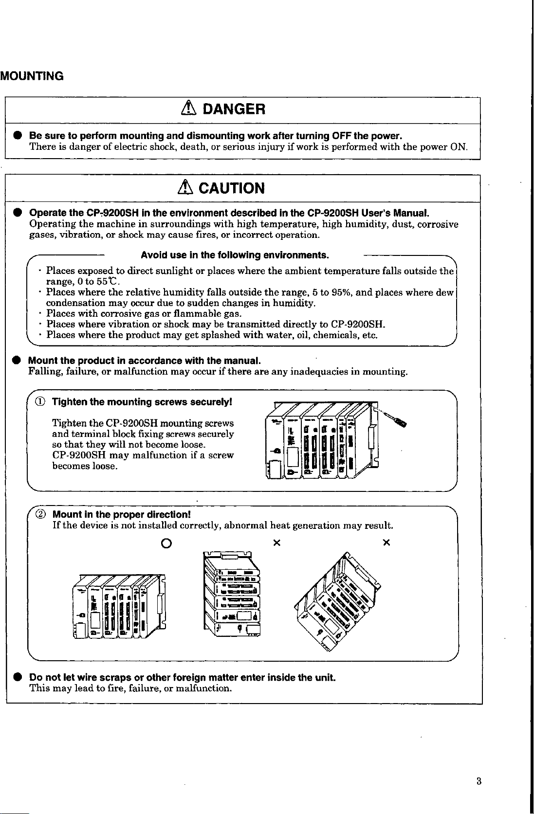
Mount
Falling,
is
vibration,
s-
Places
range,
•
Places
condensation
•
Places
•
Places
•
Places
the
(D
Tighten
perform
to
danger
the
CP-9200SH
the
exposed
Oto
where
with
where
where
product
failure,
the
mounting
of
electric
machine
or
shock
to
shock,
the
in
surroundings
in
may
Avoid
sunlight
direct
551C.
the
relative
may
corrosive
vibrationorshock
product
the
in
malfunction
or
mounting
due
occur
gas
accordance
screws
dismounting
and
death,
CAUTION
A
environment
fires,
cause
use
humidity
or
may
may
the
in
or
sudden
to
flammable
may
splashed
get
with
occur
securely!
serious
or
described
with
or
incorrect
following
places
outside
falls
changes
gas.
be
transmitted
the
manual.
there
if
work
injury
high
temperature,
environments.
where
the
in
with
water,
are
after
turning
work
if
the
in
operation.
the
ambient
range,
humidity.
directly
oil,
any
inadequacies
OFF
the
performed
is
CP-9200SH
humidity,
high
-
temperature
5
to
95%,
CP-9200SH.
to
chemicals,
in
power.
with
User's
falls
places
and
etc.
mounting.
the
Manual.
dust,
corrosive
outside
where
power
dew
ON.
>.
the
Tighten
and
so
CP-9200SH
becomes
(D
Mount
If
Do
not
This
may
the
terminal
that
they
loose.
in
the
device
ill
wire
let
lead
CP-9200SH
block
not
will
may
malfunction
the
proper
is
not
scraps
to
fire,
failure,
mounting
fixing
become
direction!
installed
o
or
other
screws
or
securely
loose.
a
if
correctly,
foreign
malfunction.
screws
screw
abnormal
SB
[i
[I
F~rd
matter
enter
heat
x
inside
«
e
it
r.f?
£
IIP
generation
>5
Sr
the
unit.
may
result.
x
3
Page 5
2
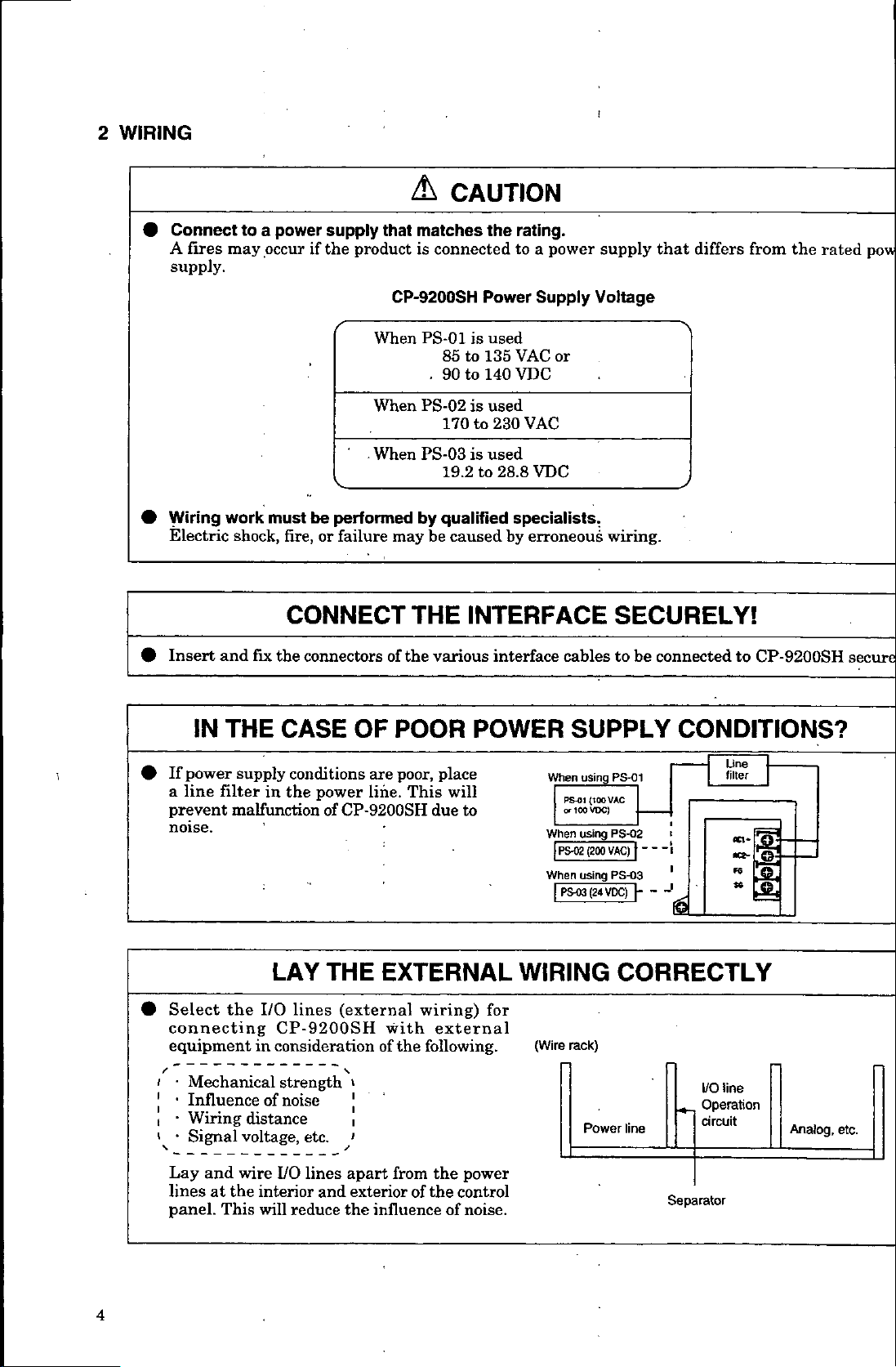
WIRING
/h
CAUTION
!
•
•
#
Connect
fires
A
supply.
Wiring
Electric
Insert
to
may
work
shock,
and
fire,
if
be
or
supply
the
power
a
occur
must
CONNECT
the
fix
connectors
that
product
CP-9200SH
When
When
When
performed
failure
may
of
matches
is
connected
PS-01
85
.
90
PS-02
170
PS-03
19.2to28.8
by
qualified
be
THE
the
various
the
rating.
a
to
power
Power
used
is
135
to
140
to
used
is
to
used
is
caused
Supply
VAC
VDC
230
VAC
VDC
specialists.
by
erroneous
or
INTERFACE
interface
supply
Voltage
wiring.
SECURELY!
cablestobe
that
differs
connected
from
the
to
CP-9200SH
rated
pow
secure
THE
IN
If
power
i
#
line
a
prevent
noise.
Select
#
connecting
equipment
•
i
•
[
,
-
•
'
Lay
lines
panel.
filter
malfunctionofCP-9200SH
the
Mechanical
Influence
Wiring
Signal
and
the
at
This
CASE
supply
wire
conditions
the
in
I/O
LAY
lines
power
THE
CP-9200SH
considerationofthe
in
strength
of
noise
distance
voltage,
I/O
interior
reduce
will
etc.
lines
and
OF
POOR
are
poor,
line.
This
EXTERNAL
(external
with
»
1
,
1
from
apart
exteriorofthe
the
influence
place
will
due
to
wiring)
external
following.
power
the
control
noise.
of
POWER
When
When
|
When
I
WIRING
for
(Wire
SUPPLY
using
PS-01
PSÿ1
VAC
\
(100
VDC)
or
t<W
using
PS-02
PS-02
(200VAC)~j
using
PS-03
(24
VDC)
PS-03
I
CORRECTLY
rack)
Power
line
CONDITIONS?
Line
filter
i
1
---
1
'
<6
---
Separator
«*
»
line
I/O
Operation
circuit
3-
<!r
--
Analog,
etc.
4
Page 6
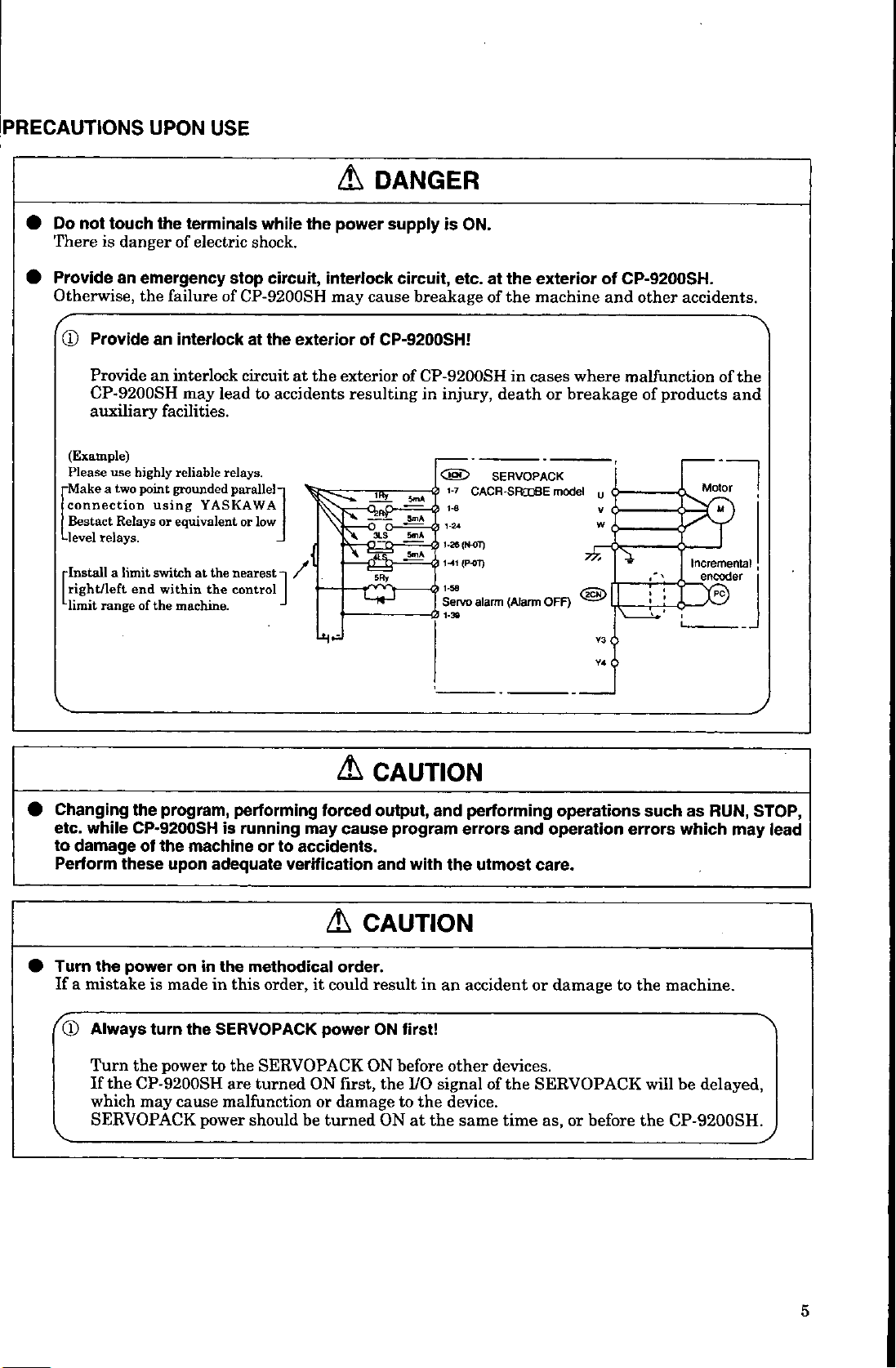
Do
not
There
touch
danger
is
UPON
the
terminals
electric
of
USE
while
shock.
the
DANGER
A
power
supply
is
ON.
Provide
Otherwise,
(D
an
emergency
the
Provideaninterlock
Provide
an
CP-9200SH
auxiliary
(Example)
use
two
a
Relays
relays.
a
limit
range
highly
point
using
switchatthe
end
of
the
Please
connection
Bestact
-level
•Install
right/left
limit
failure
interlock
may
facilities.
reliable
grounded
YASKAWA
or
equivalent
the
within
machine.
circuit,
stop
of
CP-9200SH
the
at
circuitatthe
lead
relays.
to
parallel-
low
or
nearest
control
accidents
-i
J
interlock
may
exterior
/
cause
of
CP-9200SH!
exterior
resulting
w
0
JLS°
\
'
5Ry
L"*
circuit,
breakage
of
CP-9200SH
in
5m*
3m*
5mA
-
J
etc.
injury,
CSD
>
CACR-SRCDBE
1-8
1-24
1-26
(N-OT)
(P-OT)
1-41
1-50
0
Servo
alarm
exterior
the
at
the
machine
of
cases
in
death
SERVOPACK
(Alarm
OFF)
where
breakage
or
model
of
CP-9200SH.
and
other
malfunction
of
0
V
W
Y3
Y4
accidents.
products
Motor
Incremental
encoder
B
M
of
the
and
I
Changing
while
etc.
to
damage
Perform
urn
the
T
If
a
mistake
Always
CD
Turn
the
If
which
SERVOPACK
the
program,
CP-9200SH
the
machine
of
these
upon
power
on
is
madeinthis
turn
the
power
the
CP-9200SH
cause
may
performing
is
running
or
adequate
in
the
methodical
order,
SERVOPACK
the
to
SERVOPACK
turned
are
malfunction
power
shouldbeturned
A
forced
may
to
accidents.
verification
A
order.
it
could
power
ON
or
damage
CAUTION
output,
cause
program
and
with
CAUTION
in
result
ON
first!
before
ON
the
ON
to
I/O
the
at
first,
and
the
an
other
signal
device.
the
errors
same
performing
and
utmost
accident
devices.
of
the
time
operations
operation
errors
care.
damage
or
to
SERVOPACK
or
as,
before
as
such
which
the
machine.
be
will
the
CP-9200SH.
RUN,
may
delayed,
STOP,
lead
5
Page 7
4
MAINTENANCE
AND
DISPOSAL
DANGER
A
Connect
•
short-circuit,
There
Treat
#
Do
•
There
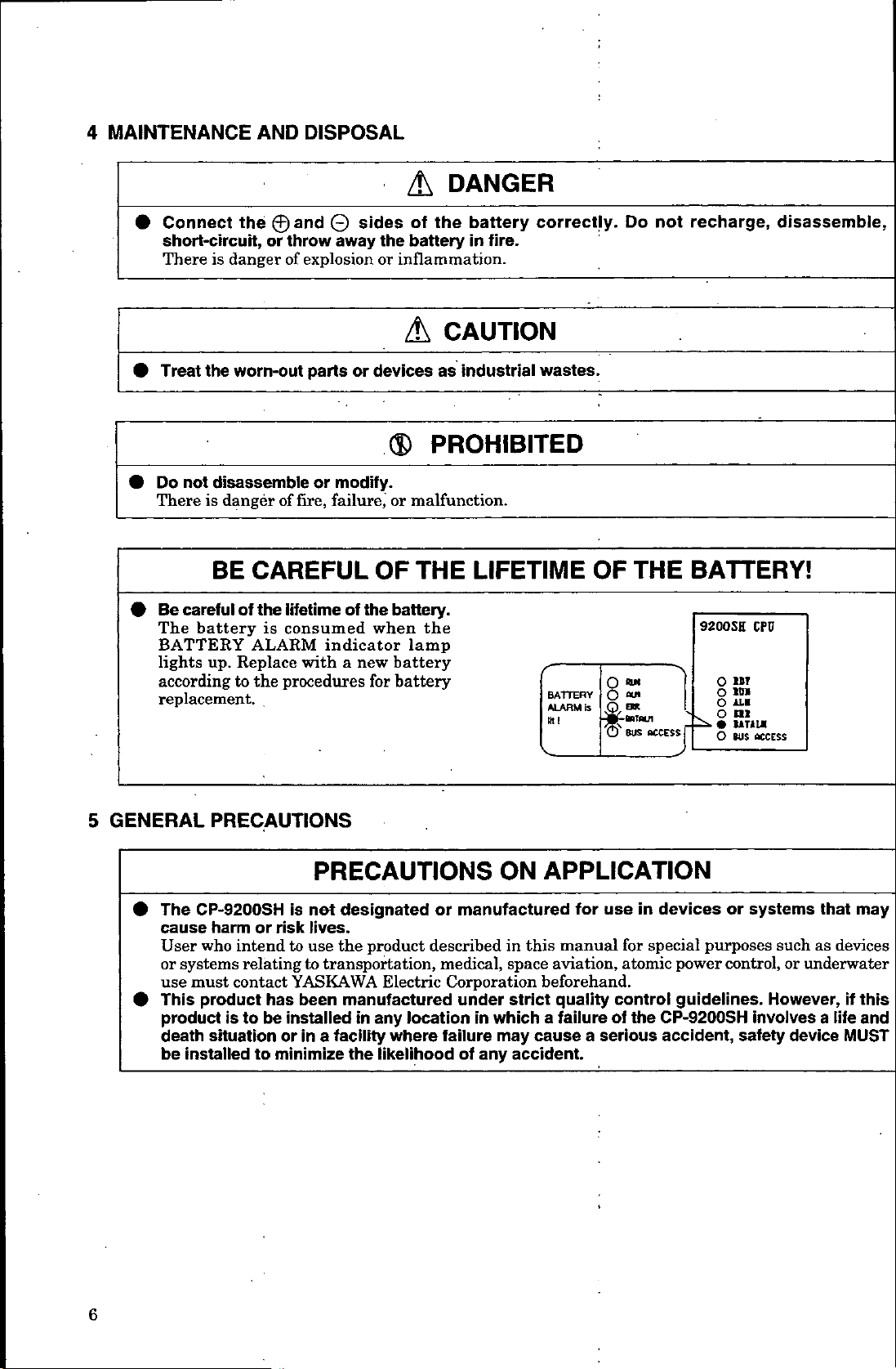
Be
•
The
BATTERY
lights
according
replacement.
danger
is
the
worn-out
disassemble
not
danger
is
BE
careful
battery
Replace
up.
to
the
0and
throw
or
explosion
of
parts
or
of
fire,
CAREFUL
lifetime
the
of
is
consumed
ALARM
the
indicator
with
procedures
sides
©
away
or
modify.
failure,
the
of
a
new
the
of
battery
the
inflammation.
or
A
devices
OF
when
for
as
PROHIBITED
®
malfunction.
or
THE
battery.
the
lamp
battery
battery
battery
in
correctly.
fire.
CAUTION
industrial
wastes.
LIFETIME
BATTERY
ALARM
mi
Do
THE
OF
o
O
*"
is
A™
-jjhBBTOUl
BUS
O'
not
recharge,
BATTERY!
9200SH
ACCESS
•n
O
O
o
O
disassemble,
CFO
11T
10*
n*
111
UT1U
tus
access
GENERAL
5
•
#
PRECAUTIONS
The
CP-9200SH
cause
User
or
use
This
product
death
be
harmorrisk
who
intend
contact
product
is
situation
relating
has
be
to
systems
must
installedtominimize
PRECAUTIONS
is
net
designated
lives.
the
use
to
to
YASKAWA
been
installed
orina
product
transportation,
Electric
manufactured
location
any
in
facility
the
where
likelihood
ON
manufactured
or
describedinthis
medical,
Corporation
under
failure
of
in
any
space
strict
which
may
accident.
cause
APPLICATION
use
for
manual
aviation,
beforehand.
quality
failure
a
serious
a
in
for
atomic
control
the
of
devices
special
power
guidelines.
CP-9200SH
accident,
or
systems
purposes
control,
involves
safety
that
such
as
or
underwater
However,
a
device
may
devices
if
this
life
and
MUST
6
Page 8
TABLE
OF
CONTENTS
1
OVERVIEW
System
1.1
Operating
1.2
1.2.1
1.2.2
1.2.3
1.2.4
Module
1.3
1.4
Pulse
•1.5
2
3
Overview
1.5.1
1.5.2
1.5.3
1.6
Module
Application
1.7
BASIC
EXPLANATIONOFFUNCTIONS
3.1
3.2
3.3
3.4
SPECIFICATIONS
Reversible
Interval
Frequency
Basic
3.4.1
3.4.2
3.4.3
3.4.4
3.4.5
3.4.6
3.4.7
3.5
Coincident
Monitoring
3.6
3.6.1
3.6.2
Structure
SVA
Setting
Setting
Setting
Monitoring
Module
Servo
Initial
Number
Counting
of
Functions
Overview
Motion
Types
Hot
Commands
of
Swapping
Precautions
Counter
Counter
Measurement
Counters
Speed
Control
Torque
Control
Position
Phase
Zero
Absolute
Latch
(Current
Control
Point
(DI
Output
Run
Pressure
Position
Motors
Indexing
3-87
Module
Operating
and
Method
1-17
Acceleration/Deceleration
3-4
3-8
Control
Return
Position
Latch
Position)
Status
Control
1-2
Number
Fixed
Values
Servo
3-2
3-8
3-12
3-63
Detection)
3-84
1-6
Parameters
of
Servo
Conditions
Parameter
and
Pulse
1-17
1-18
1-21
1-22
AND
3-6
3-16
3-72
Data
Read
3-81
(Control
Using
at
A/D
less
1-10
Parameters
Register
Multiplication
USER
PROGRAMMING
Out
with
External
Data)
Converter
One
than
1-11
(Control
1-18
from
Absolute
3-85
3-85
Revolution
Setting
for
Data)
Number
Function
Position
Signal
for
TABLE
1-12
1-13
1-14
1-15
EXAMPLES
Encoder
Pulse
Count
of
Unidirectional
OF
3-78
Value
Revolving
CONTENTS
1-1
2-1
3-1
-
4
CONTROL
SERVO
5
5.1
5.2
5.3
BLOCK
PARAMETERS
Servo
Parameter
5.1.1
Servo
of
List
5.1.2
5.1.3
Servo
5.2.1
5.2.2
5.2.3
Example
5.3.1
5.3.2
of
List
Parameter
Details
Details
Details
of
Setting
Setting
DIAGRAM
List
Fixed
Parameter
Servo
Servo
Details
of
Servo
of
Servo
of
Servo
Setting
Examples
Examples
5-2
Parameters
Parameters
5-21
Fixed
Parameters
Parameters
Parameters
Servo
Parameters
Servo
of
of
Servo
5-2
List
Settings
for
Monitor
for
for
for
Fixed
Parameters
5-7
5-16
5-21
Settings
Monitoring
5-50
Parameters
for
5-27
5-42
Setting
5-50
-
=
5-53
4-1
5-1
7
Page 9
APPENDIX
A.
Initialization
A.1
A.2
Absolute
of
Initialization
Initialization
.......
:
Encoder
Procedures
Procedures
A-2
for
Absolute
for
Absolute
-
—
—
Encoder
Encoder
-
(15-bit
(12-bit
~
-
......
.....
—
Type)
Type)
A-2
A-3
—
A
-
—
B.
Differences
B.l
B.2
B.3
B.4
C.
Switching
C.l
C.2.
between
Equivalence
of
List
List
List
When
C.1.1
C.1.2
When
C.2.1
C.2.2
Difference
of
Difference
of
Difference
between
using
Settings
(1)
Servopack
(2)
Interface
(1)
.
(2)
(3)
using
Settings
(1)
Servopack
(2)
Interface
(1)
(2)
(3)
Other
CP-9200SH
Torque
Speed
Other
CP-9200SH
Torque
Speed
CP-9200SH
for
for
for
Torque
Torque
for
A-18
control
control
control
the
for
A-20
Control
Control
Control
for
Servo
Servo
Servo
Tables
Servopack
Servopack
Servo
Control
Series
2
Control
Series
2
SVA
mode
mode
modes
Series
2
Torque
Series
2
SVA
Mode
Mode
Modes
(SVA)
Parameters
Parameters
Parameters
Module
Module
and
Fixed
and
Speed
SGD
Mode
SGD
A-18
18
A-
A-18
DR1
Control
DR1
A-20
A-20
A-20
Parameters
A-17
A-17
Mode
A-19
A-19
CP-9200SH
and
Settings
for
Monitoring
for
Each
for
Control
A-17
A-17
A-19
Control
A-19
(HSC)
CP-9200SH
A-6
A-10
Mode
17
A-
A-4
Servo
A-
12
Controller
A-5
:
8
Page 10
1.
OVERVIEW
1
OVERVIEW
methods
these
explains
items
This
chapter
operating
observe
and
for
the
system
overview
using
the
structural
the
of
SVA
module.
diagrams,
device.
Always
1-1
Page 11
1.1
System
Structure
The
CP-9200SH
machine
suitable
A
The
CP-9200SH
Manual
Use's
—
Structure
•
•
•
•
•
is
an
control.
machine
Power
Mounting
There
maximum
A
CPU
A
maximum
Motion
Three
this
in
module
motion
SVA
functions.
equipped
is
functions,
modules
PO-01
interpolation,
with
mounted,
SVB
interpolation,
and
maximum
A
With
CP-216
Communications
Various
CP-216
a
to
a
•
I/O
modules
Local
•
Other
There
sequence
composed
is
(SIE-C879-40.1)
the
of
module
bases
short
are
modules
modules
kinds
manual),
for
modules
modules
A
so
can
modules
maximum
a
so
modules
module
I/O
an
CP-216
transmission
types
interface
RS-232C
and
I/O,
modules
are
integrated
CP-9200SH
has
mounting
four
of
of
two
of
motion
pulse
or
motion
the
of
for
-
setting
mounting
can
modules
train
controller
following
the
details
for
use
bases
be
installed.
output
MECHATROLINK.
be
can
have
servo
a
with
be
can
mounted,
be
have
constant-speed
up
to
have
constant-speed
of16SVB
transmission,
mounted.
position
driver
of
with
reversible
used
position
four
64
axes
position
for
a
as
up
so
axes
can
MECHATROLINK
modules
the
(VS-616G5,
modules
module
series
modules
and
I/O
connect
interface
of
module,
interface
2000
which
fully
equipped
can
control
be
modules.
of
each
24
long
can
V,
mounting
be
with
and
bases
Each
available:
are
type
PO-01
Up
to
total
control,
a
counter,
general-purpose
control
feeding,
may
be
control
feeding,
speed
maximum
an
to
axes
44
functions
and
be
connected.
controlled.
functions
and
interval
with
mounted,
be
can
modules
SVB
VS-676H5).
provided,
are
RS-232C
a
CP-215
or
a
modules
can
between
all
with
freely
designed
Refer
to
module.
-
:
V,
and
100
bases.
connected.
independently
analog
(SVA
control,
of
four
can
constant-step
output
module,
modules
torque
axes
counter,
counter
be
controlled.
such
as
and
may
Maximum
such
as
constant-step
maximum
a
so
up
be
can
interface
interface
be
mounting
connected
including
module.
module.
connected.
bases.
functions
through
Machine
the
200
V.
executes
SVA
type
digital
the
and/or
control,
connected.
be
frequency
and
feeding.
16
feeding.
of
14
axes
224
a
CP-215
A
PO-01
axes
to
module.
positioning,
positioning,
to
The
generally
user
Controller
programs.
user
module
output
PO-01
modules)
and
maximum
zero
pulse
A
modules
zero
Both
a
may
be
can
inverter
the
interface
CP-717
necessary
programming.
CP-9200SH
(described
type
SVB
of
phase
In
measurement
control
addition,
of
11
point
return,
motor
point
be
driver
can
return,
servo
driver
connected.
controlled.
used
SVA
module,
connected
is
for
16
it
be
for
1-2
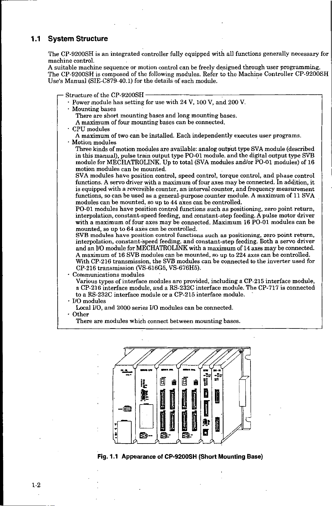
Fig.
i
Appearance
1.1
IS:
HE
©-
a
I
mr
of
CP-9200SH
mr
!i
U
(Short
-5r
r:
Mounting
y
Base)
Page 12
15=
I*
OVERVIEW
1.
z.
a
I
ff
9
i
I
a
1
9
1
f
I
I
1
7
X
a-
A
a.-
A
!*ÿ
a
A A
a.-
A
£-
A A
-«s
?!
IS
*»
U
A A
a--
L/
nm
j*
V
SM*
if*
V
u».«
3*
V
V
S'
V
v
3-
fflJ
-&
-Br
s!
S
3*
3*
3s
c
Jb-
iiiiryj
-©
n
u
—
u.
3s
3*
III
iii
_
A_A
LA
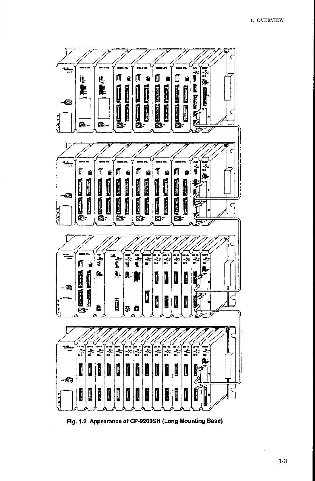
Fig.
1
.2
i.jimte
3s3*3"
I
III
ii
_
_
A__A
A
Appearance
gS
A
3s 3s3*3s
II
in
_
AX>I_X_X_Xÿ_A__AL_AL_Aÿ
CP-9200SH
of
ii
3s
3*
3'
BIB
i>i
(Long
Mounting
3*
if]
ifj>x
3*
Base)
,
Jb-
v
1-3
Page 13
/DO
PI
••
-<3
.
5=?
IX)
Expansion
module
(2000s«nes
VO)
Comrru>
caws
nwUe
CPU
module
1*0000
(0*0000)
*
IW13PF
(OW3PP)
DM)
DO
00
000
IMG
\
8MU023
(CPU#1)
UWO0OO
VWSH7
Expansion
module
(2000
Common
DI/DO
•
-U
5=?
1/0
senes
I/O)
memory
o
ComnuV
cations
nxxUe
CPU
module
1*0000
(CW000)
IVW3PP
(CW13PF)
DM0000
SWBOOO0
\
SWBI0J3
(CPU
MWOOOO
MW27I7
#2)
Fig.
Servo
Servo
1.3
driver
driver
SVA
1
Axis
3
Axis
2
3
3
Axis
Axis
3
4
3
SVA
Axis
1
2
Axis
3
Axis
Axis
4
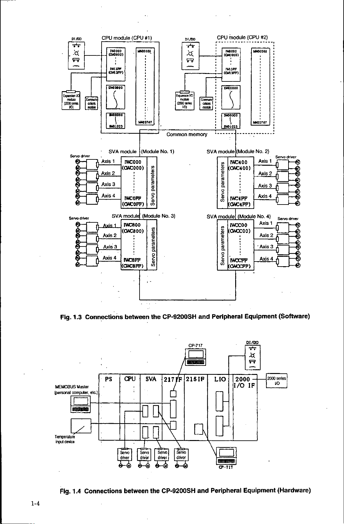
Connections
module
wcooo
(GMCOOO)
MCOFF
(CMC
OFF)
module
IVC800
(QAC800)
MC8FF
(OAC8FF)
between
(Module
S
£
E
2
I
OJ
V)
(Module
2
O)
Q>
E
2
2.
o
£
o
'
1
the
1)
No.
3)
No.
CP-9200SH
SVA
SVA
and
module
IWC400
2?
0)
(CUC400)
a>
E
ro
a.
o
£
<D
MC4FF
to
(CWC4FF)
module!
IWCC00
m
(CWCC00)
5
O)
E
2
to
o
<D
IVrCCFF
C0
(CMCCFF)
Peripheral
(Module
(Module
Equipment
No.
Axis
Axis
Axis
Axis
No.
"Axis
Axis
Axis
Axis
2)
4)
1
2
r
3
L
4
r
1
2
3
4
Q
£J
Servo
driver
Servo
driver
0
(Software)
1-4
MEMOBUS
computer,
(personal
Temperature
device
input
.4
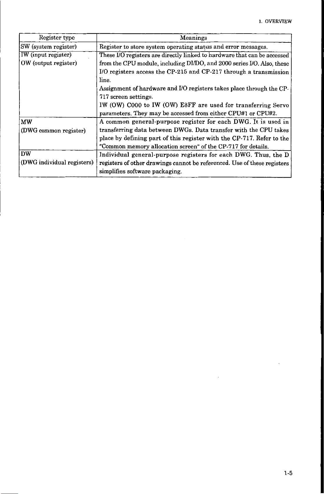
Fig.
1
Master
etc.)
Connections
PS
CPU
Servo
driver
5-®
between
SVA
tm
X
Servo
driver
&-®
217
Vn
Servo!
j
driver
&-<k
CP-9200SH
the
rF
Servo
I
|
driver
&-<k)
CP-717
[
215
IF
\n
and
LIO
I/O
\
—
CP-717
Peripheral
PI
/DO
»
•
F?
2000
-
IF
Equipment
2000
series
I/O
(Hardware)
Page 14
1.
OVERVIEW
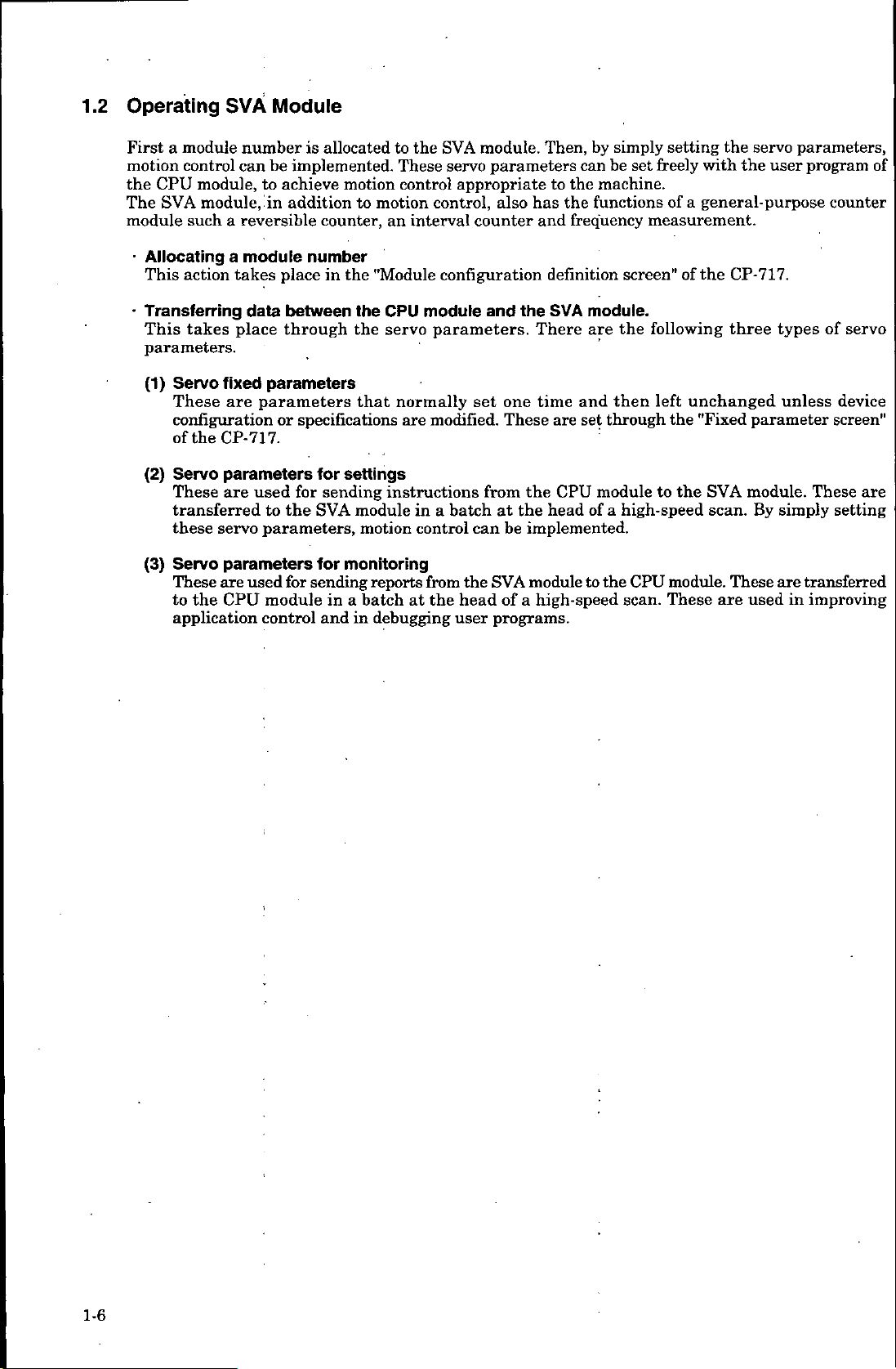
(system
SW
(input
IW
OW
MW
(DWG
DW
(DWG
Register
register)
(output
common
individual
type
register)
register)
register)
registers)
Register
These
from
I/O
to
registers
I/O
CPU
the
registers
line.
Assignment
screen
717
(OW)
IW
parameters.
common
A
transferring
by
place
"Common
defining
Individual
registers
simplifies
of
system
store
directly
are
to
the
IW
may
including
(OW)
be
module,
access
of
hardware
settings.
COOO
They
general-purpose
data
between
of
part
memory
general-purpose
other
software
allocation
drawings
packaging.
Meanings
operating
status
linkedtohardware
DI/DO,
I/O
and
registers
CP-215
and
E8FF
accessed
DWGs.
this
cannot
from
register
Data
register
screen"
registers
be
and
and
2000
CP-217
are
through
takes
used
either
each
for
transfer
the
with
the
of
CP-717
for
each
referenced.
error
messages.
that
series
place
for
transferring
CPU#I
DWG.
with
CP-717.
for
DWG.
Use
be
can
I/O.
Also,
a
transmission
through
CPU#2.
or
is
It
the
CPU
Refer
details.
Thus,
of
these
accessed
these
the
CP-
Servo
used
in
takes
to
the
_
D
the
registers
1-5
Page 15
1.2
Operating
SVA
Module
Firstamodule
motion
the
The
module
CPU
SVA
control
module,
module,
such
Allocating
This
action
•
Transferring
This
takes
parameters.
(1)
Servo
These
fixed
are
configuration
of
CP-717.
the
Servo
(2)
These
parameters
are
transferred
these
servo
Servo
These
the
to
parameters
are
CPU
(3)
application
number
be
can
to
in
reversible
a
module
a
takes
data
place
parameters
parameters
or
used
to
parameters,
used
module
control
is
allocatedtothe
implemented.
achieve
addition
place
between
through
motion
counter,
number
the
in
to
the
the
that
specifications
for
settings
sending
for
the
for
module
SVA
for
monitoring
sending
a
in
in
and
motion
These
control
an
control,
interval
motion
"Module
CPU
module
parameters.
servo
normally
modified.
are
instructions
a
in
control
reports
batchatthe
from
debugging
module.
SVA
parameters
servo
appropriate
also
counter
configuration
and
the
one
set
These
the
from
batchatthe
be
can
the
SVA
head
of
a
programs.
user
simply
by
Then,
be
can
the
machine.
to
has
and
functions
the
frequency
definition
module.
SVA
There
time
are
CPU
head
are
and
then
through
set
moduletothe
of
a
implemented.
the
module
to
high-speed
setting
freely
set
a
of
measurement.
screen"
the
of
following
unchanged
left
the
high-speed
module.
CPU
These
scan.
servo
user
parameters,
program
with
the
the
general-purpose
the
CP-717.
types
three
unless
"Fixed
SVA
scan.
are
parameter
module.
By
These
used
simply
transferred
are
improving
in
counter
of
servo
device
screen"
These
setting
of
are
1-6
Page 16
1.
OVERVIEW
usu
\o
Make
driver
Connect
Turn
9200SH,
Register
numberonthe
screen"
and
and
the
the
power
and
the
of
connect
the
CP-717
the
Try
running
"parameter
a
module.
SVA
and
ON
to
CP-717.Not*
the
SVA
module
"Module
CP-
17.
7
setting"
to
cable
v
the
CP-9200SH.
t
\
the
servo
1
\f
and
configuration
the
servo
connect
driver,
allocate
motor
function
the
the
a
module
definition
on
servo
CP-
without
the
CP-
creating
7
17.
a
<Reference
Machine
Manual
Controller
(SIE-C879-40.1)
<Reference
Control
(SIE-C877-17.4,
Pack
<Reference
Machine
Manual
Refer
number"
Controller
(SIE-C879-40.1)
to
program
user
manual>
manual>
CP-717
manual>
1.2.1
CP-9200SH
Operation
-17.5)
CP-9200SH
"Setting
by
using
the
the
User’s
Manual
User’s
module
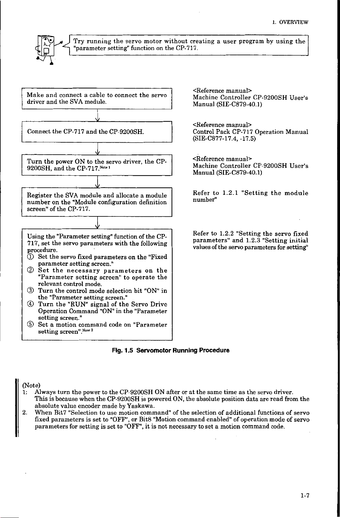
Using
set
717,
procedure.
(X)
Set
parameter
Set
CD
"Parameter
relevant
(D
Turn
the
Turn
©
Operation
setting
Set
©
setting
(Note)
Always
1:
This
absolute
When
2.
fixed
parameters
the
"Parameter
the
servo
the
servo
setting
the
necessary
control
the
control
"Parameter
the
"RUN"
Command
screen."
motion
a
screen".
turn
is
because
value
"Selection
Bit7
parameters
for
parameters
fixed
setting
mode.
mode
setting
command
Note
power
the
when
encoder
is
setting
\f
setting"
parameters
screen."
parameters
screen"
selection
screen."
signal
of
"ON"
code
2
the
to
the
CP-9200SH
made
to
use
set
to
"OFF",
is
set
function
with
the
on
to
operate
bit
the
Servo
in
Fig.
"Parameter
the
on
"Parameter
.5
1
CP-9200SH
by
Yaskawa.
motion
or
to
"OFF",
the
of
CP-
following
"Fixed
the
the
on
the
in
"ON"
Drive
Servomotor
ON
powered
is
command"
"Motion
Bit8
it
is
not
Running
after
or
ON,
of
the
command
necessary
Refer
parameters"
values
Procedure
the
at
the
absolute
selection
to
set
1.2.2
to
the
of
same
time
position
additional
of
enabled"
motion
a
"Setting
and
servo
as
of
the
"Setting
1.2.3
parameters
the
servo
are
data
functions
operation
command
servo
for
driver.
read
mode
code.
fixed
initial
setting"
the
from
of
servo
of
servo
1-7
Page 17
U5ÿ
\D
creating
try
Next,
confirmation
test,
a
simple
taking
user
the
program.
simple
speed
We
will
control
discuss
mode
performing
example.
as
an
a
servo
motor
in
the
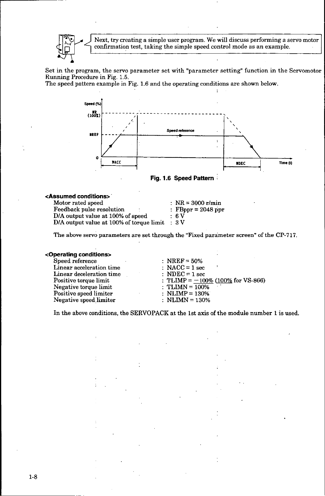
Set
Running
speed
The
<Assumed
Motor
Feedback
output
D/A
D/A
output
The
above
program,
Procedure
pattern
Speed
{1001)
HEP
conditions>
rated
speed
pulse
value
value
servo
the
servo
Fig.
in
example
{%)
0
HACC
resolution
100%
at
100%
at
parameters
parameter
1.5.
Fig.
in
of
of
1.6
speed
torque
are
set
set
the
and
Fig.
1
limit
through
with
operating
Speed
reference
.6
Speed
NR
FBppr
6
V
3
:
V
the
"parameter
conditions
Pattern
r/min
3000
=
2048
=
"Fixed
parameter
setting"
:
ppr
are
»»EC
screen"
function
shown
below.
of
the
in
the
Time
CP-717.
Servomotor
(t)
cOperating
Speed
Linear
Linear
Positive
Negative
Positive
Negative
the
In
conditrons>
reference
acceleration
deceleration
torque
speed
speed
conditions,
limit
limit
limiter
limiter
torque
above
time
time
the
SERVOPACK
NREF
NACC
NDEC
TLIMP
TLIMN
NLIMP
NLIMN
the
at
=
=
=
=
=
=
1st
50%
sec
1
sec
1
-100%
100%
130%
130%
=
'
1100%
axisofthe
VS-866)
for
module
number1is
used.
1-8
Page 18
OVERVIEW
1.
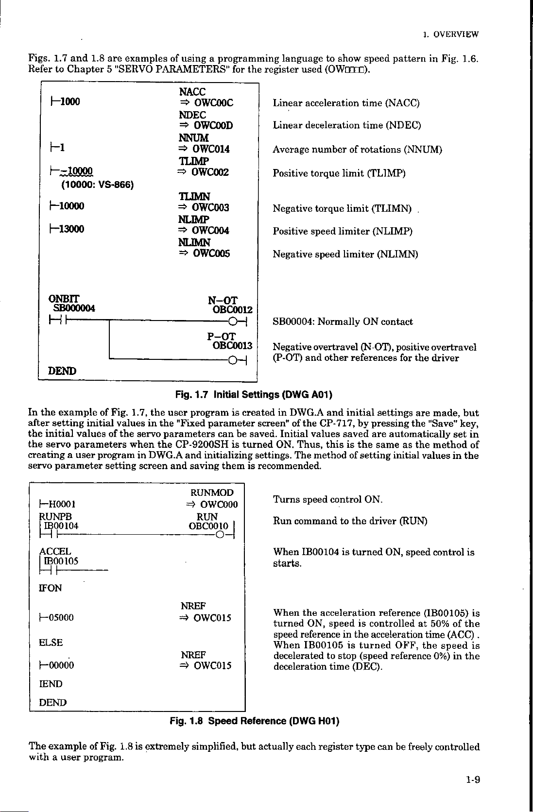
Figs.
Refer
and
1.7
to
Chapter
Hooo
hi
10000
h—
(10000:
—
10000
I
|
13000
—
ONBIT
SB000004
DEND
1.8
are
5
VS-866)
examples
"SERVO
using
of
PARAMETERS"
programming
a
NACC
OWCOOC
=>
NDEC
=s>
OWCOOD
NNUM
=>
OWC014
TUMP
=>
OWC002
UIMN
=>
OWC003
NUMP
=>
OWC004
NUMN
=>
OWC005
N-OT
OBC0012
P-OT
OBC0013
for
OH
the
language
register
Linear
Linear
Average
Positive
Negative
Positive
Negative
SB00004:
Negative
(P-OT)
speed
show
to
(OWODDD).
used
acceleration
deceleration
numberofrotations
torque
torque
speed
speed
Normally
overtravel
and
other
time
time
(TLIMP)
limit
limit
limiter
limiter
ON
(N
references
(TLIMN)
pattern
(NACC)
(NDEC)
(NLIMP)
(NLIMN)
contact
OT),
positive
(NNUM)
.
for
the
Fig.
in
overtravel
driver
1.6.
the
In
setting
after
the
initial
the
servo
creating
servo
f-HOOOl
UNPB
IB
P
ACCEL
I
IB00105
IFON
1-05000
ELSE
(-00000
example
initial
valuesofthe
parameters
a
user
parameter
00104
Fig.
of
values
program
setting
1
.7,
in
servo
when
in
screen
Fig.
the
user
the
parameters
the
DWG.A
and
Initial
1.7
program
"Fixed
parameter
can
CP-9200SH
initializing
and
saving
RUNMOD
=>
them
OWCOOO
RUN
OBCOOlOl
o
NREF
=4
OWC015
NREF
OWC015
=>
Settings
is
created
screen"
be
saved.
is
turned
settings.
is
recommended.
(DWG
in
Initial
ON.
Turns
Run
When
starts.
When
turned
speed
When
decelerated
A01)
DWG.A
of
the
CP-717,
values
Thus,
The
method
speed
command
IB00104
the
acceleration
ON,
reference
IB00105
deceleration
and
initial
by
saved
thisisthe
of
setting
control
the
to
is
turned
speed
is
in
the
is
turned
stop
time
(speed
(DEC).
to
settings
pressing
automatically
are
same
as
initial
ON.
driver
controlled
(RUN)
ON,
speed
reference
acceleration
OFF,
reference
are
the
"Save"
the
values
(IB00105)
at
50%
time
the
made,
key,
set
method
in
control
of
(ACC)
speed
0%)
in
but
in
of
the
is
is
the
.
is
the
END
DEND
The
with
example
user
a
Fig.
of
program.
1.8
is
extremely
Fig.
Speed
1.8
simplified,
Reference
but
actually
(DWG
each
H01)
register
type
can
be
freely
controlled
1-9
Page 19
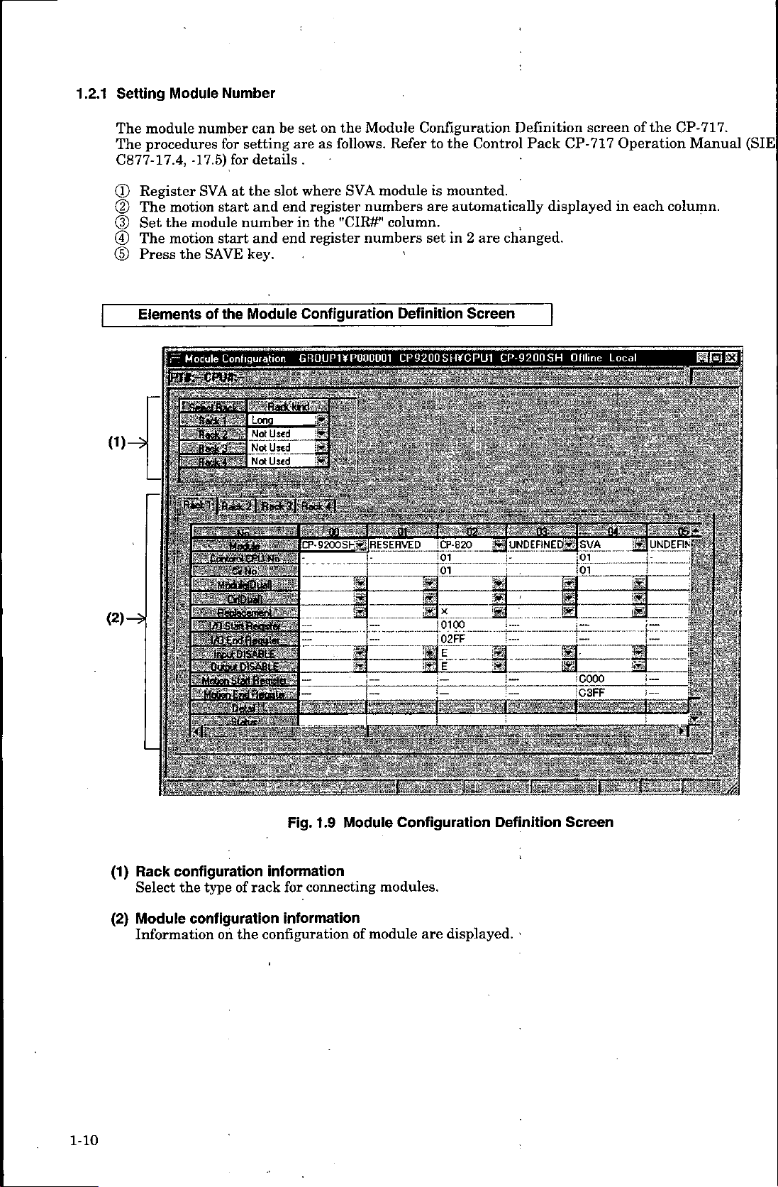
1.2.1
Setting
The
The
C877-17.4,
Module
module
procedures
Number
number
for
-17.5)
setting
for
be
can
details
set
are
.
on
follows.
as
the
Module
Refer
Configuration
the
to
Control
Definition
Pack
CP-717
screen
the
of
Operation
CP-717.
Manual
(SIE
(D
(D
(3)
©
(5)
0)ÿ
(2)—ÿ
Register
The
motion
the
Set
The
motion
Press
the
Elements
Module
F
i£
,1C—
5
IF
a,
II
it
at
start
start
the
Coni
3''
the
and
number
and
key.
Module
iguiatiori
-
SVA
module
SAVE
of
,
:asd<
s:s
r"r.ua
Contordl
CPU
’C«
:lÿMaifaOita8v7>ÿ
*
•
Ho
c»<Du«n
l/QCntjflaoiiter
OiSASCE
tncui
’
OuiaU
DISABLE
Slat
Register
Motion
where
slot
end
in
end
Configuration
GROUPUf
~
No
..
:
SVA
register
the
"CIR#"
register
module
numbers
column.
numbers
P000001
is
mounted.
are
set
in
'
Definition
9200
CP
S
..
•
automatically
changed.
are
2
Screen
HVCPU1
CP-9200
>
.
-
displayed
Online
SH
-1
.
f.
1
'M
-f
D1
-
'ÿ'g&OSHÿRESERVED
iCP-820
02-
'
'I
SI
UNDEFINEDÿ
Hj
foi
_
[0100
EI=EJ:_
fiK
'"~jT
IpVA
01
:01
i.““
cooo
each
in
Local
nil.
column.
.
..
;
....
.....
-
--
JW
.....
v
‘
1
lijuNDEFlNi
-*
“
t-
vos"*
:
1
a
•
;
j
i
Rack
(1)
Select
Module
(2)
Information
i|
'
configuration
type
on
of
the
the
configuration
Fig.
information
rack
configuration
connecting
for
information
1.9
Module
of
module
v
*F_
Configuration
modules.
are
-
Definition
displayed.
Screen
1-10
Page 20
OVERVIEW
1.
Setting
Set
the
CP-
7
17.
setting
Elements
0)
(2)
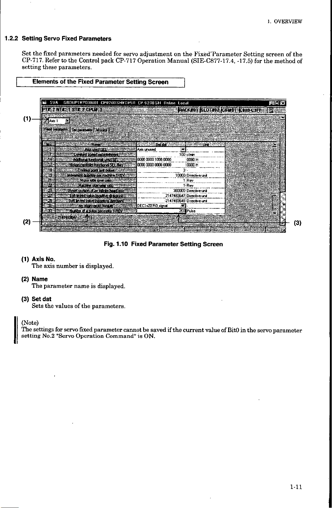
Servo
fixed
Refer
these
SVA
\ii
rTr-
Axis
I
I
gat*
i-18-
y'22~
mm
a
33
Fixed
Parameters
parameters
the
to
parameters.
the
of
GROUP1¥POUUU01
NTr
2
i
srr
1
needed
Control
Fixed
?
ow
Parameter
mmP
AT
•
;
•
•
•
~
:
V'MoeentMrÿtottfentiSELItaa
*:T’
;
-
.
TSdlifaiiw
_
'
'
Curalirt
-tetWeninl
—
*noBaniepiniloi)iifc~
"
faceuttrisn
tawed
jelneoatÿ
'
'
*
"
”
-
for
servo
pack
CP-717
Setting
CP9200SH*CPU1
1
..
1
'
•
Men
dfecfaart'
.
*
‘
’’
;i
'
-
V
nriatA’rfmnrt
fw
*tmBWiTBEVT~-
*
adjustment
Operation
Screen
CP
9200SH
S
0000
00001000
~
ooooooroixrapoog
‘>
’
.....
-
”c”z"*“"
[rÿi
’
the
on
Manual
Online
‘
0000
.....
:i
Fixed'Parameter
(SIE-C877-17.4,
Local
SI
•
lOOii/inii
u-m
:
4
__
pE:r
'
_
Setting
-17.5)
for
«
screen
the
method
HR
l
Cl
:
of
the
of
:
:::
MMm
mm
..
Is
-
-
jv
-
>
i
.
—
*«
mssssi
iv
;
3-
O)
Axis
(1)
The
(2)
Name
The
(3)
Set
Sets
(Note)
The
settings
setting
No.
axis
number
parameter
dat
the
valuesofthe
for
No.2
"Servo
servo
displayed.
is
is
name
parameters.
fixed
Operation
Fig.
displayed.
parameter
Command"
1.10
Fixed
cannot
Parameter
be
savedifthe
is
ON.
Setting
current
Screen
value
of
BitO
in
the
servo
parameter
1-11
Page 21
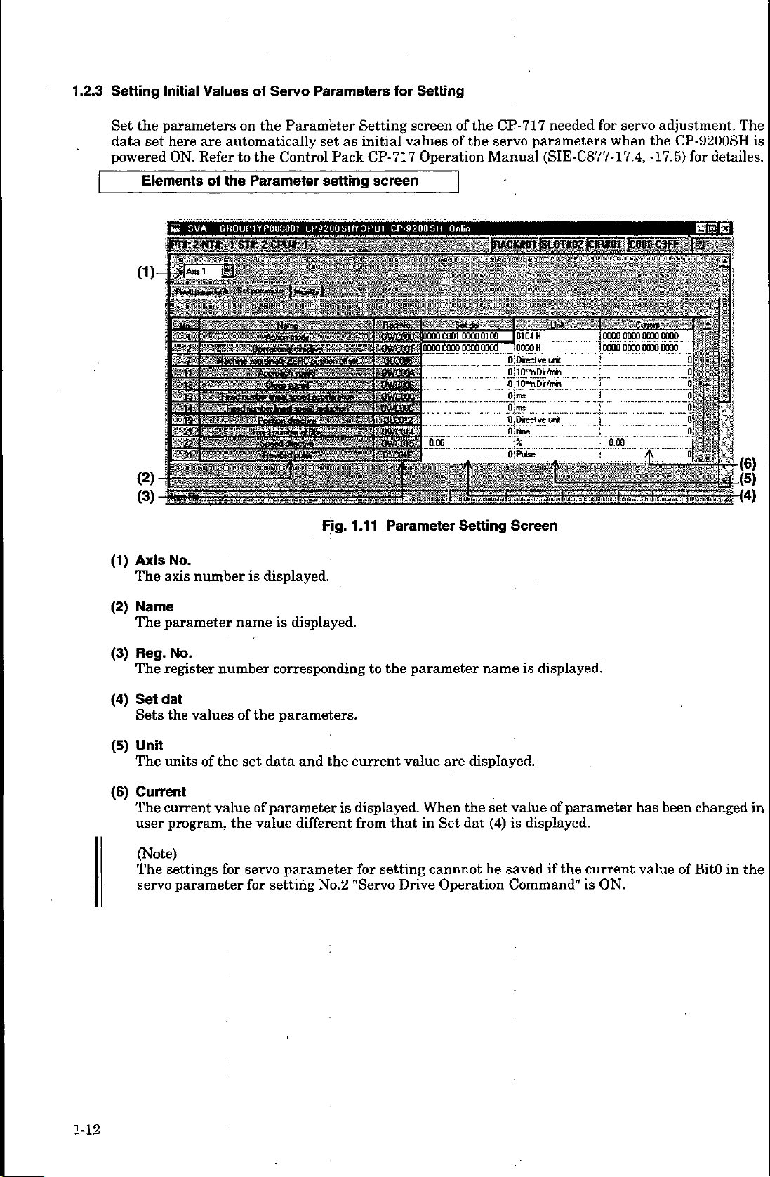
1.2.3
Setting
Initial
Values
of
Servo
Parameters
for
Setting
the
Set
data
set
powered
Elements
(3)
parameters
here
are
ON.
Refer
of
SVA
tes
r~
nr-
777
777:
•
L:
•
7
•
•
•
-F
Rl
1
the
on
automatically
to
the
GROUPJVPOOOOOI
-f,
•
•
Z".;'
Parameter
the
Control
Parameter
m
‘
Setting
initial
as
set
Pack
setting
CP92005I«CPUI
.-•••
1
.11
Fig.
screen
values
CP-717
Operation
screen
CP
9200SH
:-mi/rÿ;8oooci
Mÿm-‘loooc
cum
h&x
cote'
SSB
vmcmr
mmm
Parameter
of
the
CP-717
the
of
servo
Manual
Qrlin
0100
QOOC
-
'I
I01
looooH
.Pis?-
0.
:?
OiPube
ouoi
0000 0000
iido
ccou
-
zzzz*~<
mmm
Setting
Screen
needed
parameters
(SIE-C877-17.4,
-ÿtMt
H
ye
.
'
~
in*
•
-
o<
Direct
z
-
m
is
for
when
servo
-
-URO*
adjustment.
the
CP-9200SH
-17.5)
for
‘
~
F
;
1!
.9
Hi
9
9
0
;F
Jft!
The
detailes.
1
1
-
-
a
Z!
(6)
-
r
.
is
(1)
(2)
(3)
(4)
(5)
(6)
Axis
No.
axis
The
Name
parameter
The
No.
Reg.
register
The
Setdat
the
Sets
Unit
units
The
Current
The
current
program,
user
(Note)
settings
The
servo
number
number
valuesofthe
the
of
value
for
parameter
is
name
set
the
servo
for
of
value
displayed.
displayed.
is
corresponding
parameters.
data
and
the
parameter
different
parameter
setting
No.2
to
current
displayed.
is
from
for
"Servo
the
value
that
setting
Drive
parameter
are
the
When
dat
Set
in
cannnot
Operation
is
name
displayed.
value
set
(4)
is
be
savedifthe
Command"
displayed.
of
parameter
displayed.
current
is
ON.
has
value
been
of
changed
BitO
in
in
the
1-12
Page 22
1.
OVERVIEW
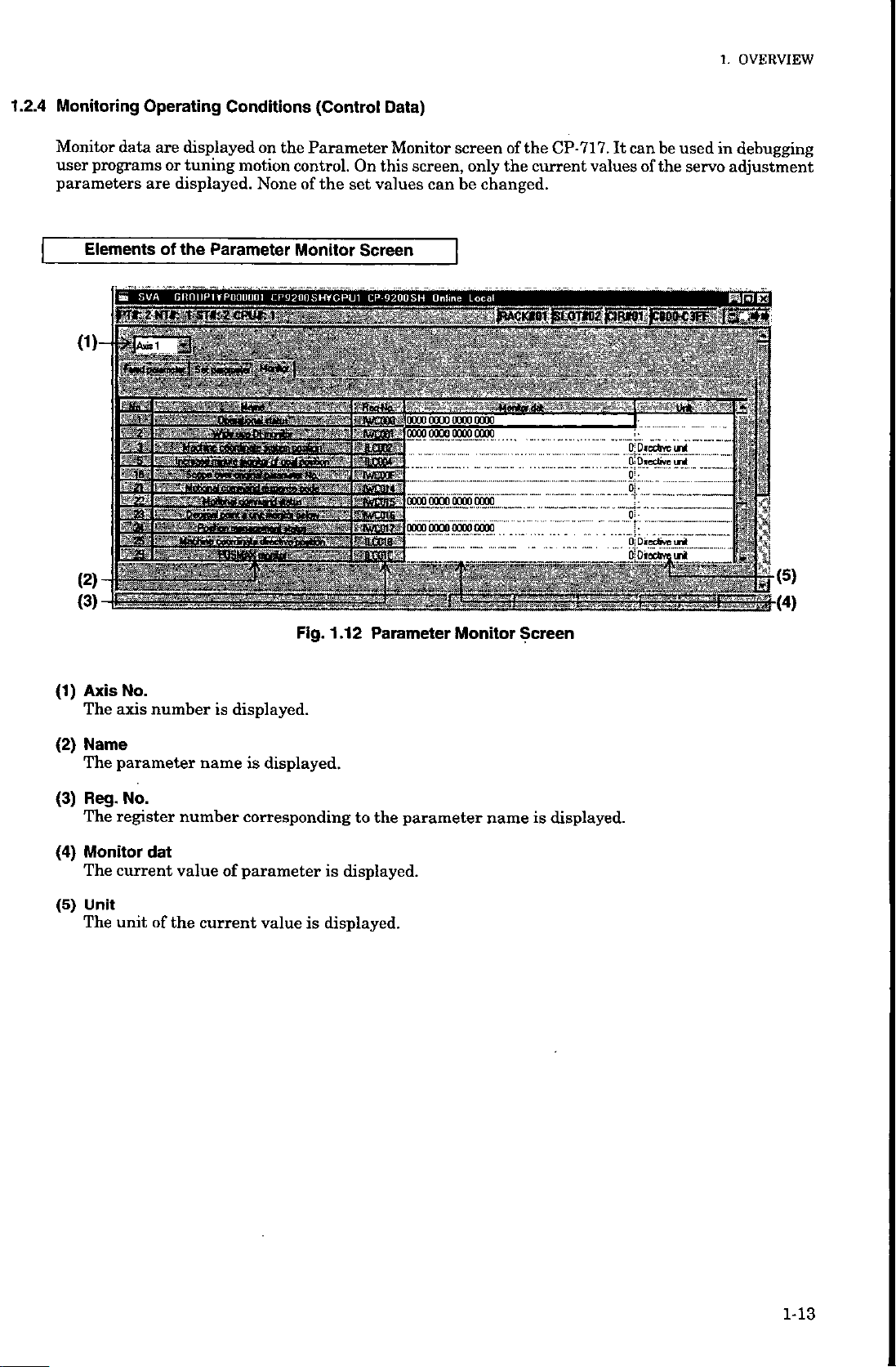
Monitoring
Monitor
user
parameters
data
programs
Elementsofthe
(D
'
>'!
(2)
(3)
Operating
displayed
are
tuning
or
are
displayed.
SVA
GIIQIJPIYPOOUOOI
"tv
-
-
‘
3
3S»inftfei
1
1-
.v
Conditions
motion
Parameter
'’jqv
•
~
OBbiiiiyMltMm1*
-
(Control
the
on
Parameter
control.Onthis
Noneofthe
Monitor
CP9200SHYCPU1
V*
....
.‘rÿr?;
8cn*':~
v
»w?*y
_
Data)
Monitor
values
set
Screen
CP-920QSH
.
.....
>
SWCOOC
|WC8W-
amass
"g.COM
!
’
’
riWCOOF
;:;<wrnn
gwcms
£3WC0tfi-:
?
news
gtCOICi
screen
only
be
changed.
Local
the
screen,
can
m
fiACKIBI
_
|
0000
0000
(TO
rao
ooro
60000660
nmacnoggqogmTr
0000
0000
00000000
oooo
Hetiadik
-
of
the
current
CP-717.
It
values
ElOTOTZ
jCtRMI
...
can
of
jC8P(K3If
0!
be
the
used
servo
debugging
in
adjustment
jjQFi
;
il
1
s
Hgf-(4)
(5)
(1)
(2)
(3)
(4)
(5)
Axis
No.
The
axis
Name
The
parameter
No.
Reg.
register
The
Monitor
The
current
Unit
unit
The
number
number
dat
value
of
the
displayed.
is
is
name
corresponding
parameter
of
current
Fig.
displayed.
is
value
1
Parameter
.12
to
the
displayed.
is
displayed.
Monitor
parameter
name
Screen
displayed.
is
M3
Page 23
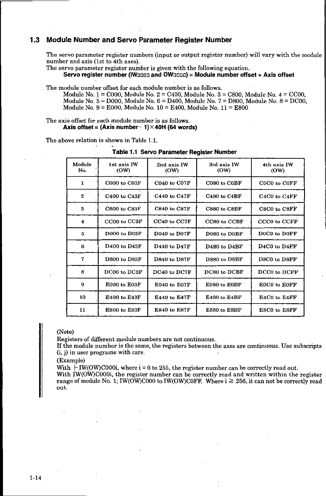
1.3
Module
Number
and
Servo
Parameter
Register
Number
The
servo
number
The
servo
The
module
Module
Module
Module
The
axis
above
The
parameter
and
axis
parameter
Servo
register
number
No.
No.
No.
for
offset
Axis
offset
relationisshown
Module
No.
1
2
3
4
(1st
1
5
9
each
(Axis
=
register
to
register
number
offset
C000,
=
D000,
=
E000,
=
module
Table
1st
C000
C400
C800
CC00
axes).
4th
number
(IWODOD
for
Module
Module
Module
number-
in
axis
(OW)
C03F
to
C43F
to
C83F
to
CC3F
to
numbers
each
module
No.
No.
No.
number
1)X40H
Table
1.1.
1.1
Servo
IW
(input
is
and
given
OWnoao)
or
with
number
0400,
=
2
6
D400,
=
E400,
10
=
follows.
as
is
(64
Parameter
axis
2nd
(OW)
to
C040
C440
to
C840toC87F
to
CC40
output
the
is
Module
Module
Module
words)
IW
C07F
C47F
CC7F
register
following
Module
=
as
follows.
No.
Register
C080
C480
C880
CC80
number
No.
No.
Number
3rd
number)
equation.
3
C800,
=
D800,
7
=
11
=
axis
(OW)
COBF
to
C4BF
to
C8BF
to
to
CCBF
E800
IW
will
offset
Module
Module
vary
Axis
+
No.
No.
4th
COCO
C4C0
C8C0
CCCO
with
axis
(OW)
to
to
to
to
offset
4
=
8
=
IW
COFF
C4FF
C8FF
CCFF
module
the
CC00,
DC00,
(Note)
Registers
the
If
module
(i,
j)
user
in
(Example)
|-
With
IW(OW)C000i,
With
range
of
out.
5
6
7
8
9
10
11
of
DOOO
D400
D800
DCOO
E000
E400
E800
different
numberisthe
programs
IW(OW)C000i,
module
No.
to
D03F
D43F
to
to
D83F
DC3F
to
E03F
to
to
E43F
E83F
to
module
numbers
same,
with
care.
where
i
register
the
IW(OW)COOO
1;
D040
D440
D840toD87F
DC40toDC7F
E040
E440
E840
are
the
registers
to
0
255,
=
number
IW(OW)C0FF.
to
to
to
to
to
to
the
D07F
D47F
E07F
E47F
E87F
not
register
can
D080
D480
D880
DC80
E080
E480
E880
continuous.
between
number
correctly
be
Where
the
to
to
to
to
EOBF
to
to
E4BF
E8BF
to
axes
read
i
DOBF
D4BF
D8BF
DCBF
can
and
256,
continuous.
are
correctly
be
written
it
DOCO
D4C0
D8C0
DCCO
E0C0
E4CO
E8C0
can
read
within
not
to
to
to
to
to
to
to
be
DOFF
D4FF
D8FF
DCFF
EOFF
E4FF
E8FF
Use
subscripts
out.
register
the
correctly
read
1-14
Page 24
1.
OVERVIEW
1.4
Pulse
There
Counting
are
counting,
differential
are
There
Sign
(With
can
type
12
method
•
Pulse
Pulse
Pulse
If
rotation
(With
5
Pulse
Pulse
Pulse
If
rotation
Up/Down
A
Pulse
B
Pulse
•
type
A/B
(During
The
The
(During
The
The
Please
differential
5
V
three
pulse
input
three
be
selected
V
pull
is
A
is
B
B
(negative
V
differential
A
is
is
B
B
(negative
type
input
input
12
V
count
count
V
differential
5
count
count
that
note
Method
types
counting
C
in
and
12
methods
up
collector
adding
an
sign.
a
"Low",
is
adding
an
sign.
a
"High",
is
is
the
addition
is
subtraction
the
pull
up
is
upped
is
downed
upped
is
is
downed
the
lead
input.
and
Pulse
input
of
pulses,
control.
V
up
pull
counting
of
collector
independently
input)
subtracting
and
the
forward
frequency)
in
input)
subtracting
and
the
forward
frequency).
in
pulse.
pulse.
if
the
the
input)
phase
phase
collector
if
input)
phase
the
if
if
phase
the
and
lag
of
Multiplication
'pulse
choice
A
input.
pulses
with
each
for
pulse.
rotation
pulse.
rotation
(Positive
(Negative
pulse
of
pulse
of
pulse
of
pulse
of
phases
the
pulse
A,
may
and
A
axis.
(positive
(positive
frequency)
frequency)
A
input
input
A
A
input
input
A
opposite
are
B,
made
be
sign
B:
in
leads
lags
lags
leads
Function
pulse
and
for
type,
frequency).
frequency).
in
pulse
pulse
pulse
B.
pulse
between
Pulses
C.
pulses
Up/Down
(Positive
B.
(Negative
B.
(Positive
(Negative
B.
12
A,
it
If
it
If
pull
V
A
and
B,
and
C
and
type,
"High",
is
is
"Low",
frequency)
frequency)
frequency)
frequency)
up
collector
B
are
between
type.
AJB
the
reversed
the
reversed
input
used
in
5
V
The
and
There
is
an
multiplication
Single
Double
Quadruple
Up/Down
shown
in
counter
Table
multiplication
(X2),
quadruple
or
multiplication
multiplication
multiplication
pulse
and
1.2.
function
(XI)
(X
2)
(X4)
counting
rising
for
multiplication
Count
:
:
Count
:
Count
methods
at
at
at
and
and
(X4)
rising
rising
rising
the
falling.
may
be
pulse
and
and
relation
Single
selected.
A.
falling
falling
with
multiplication
of
pulse
of
pulses
both
the
multiplication
A.
A
and
(XI),
B.
function
double
are
1-15
Page 25
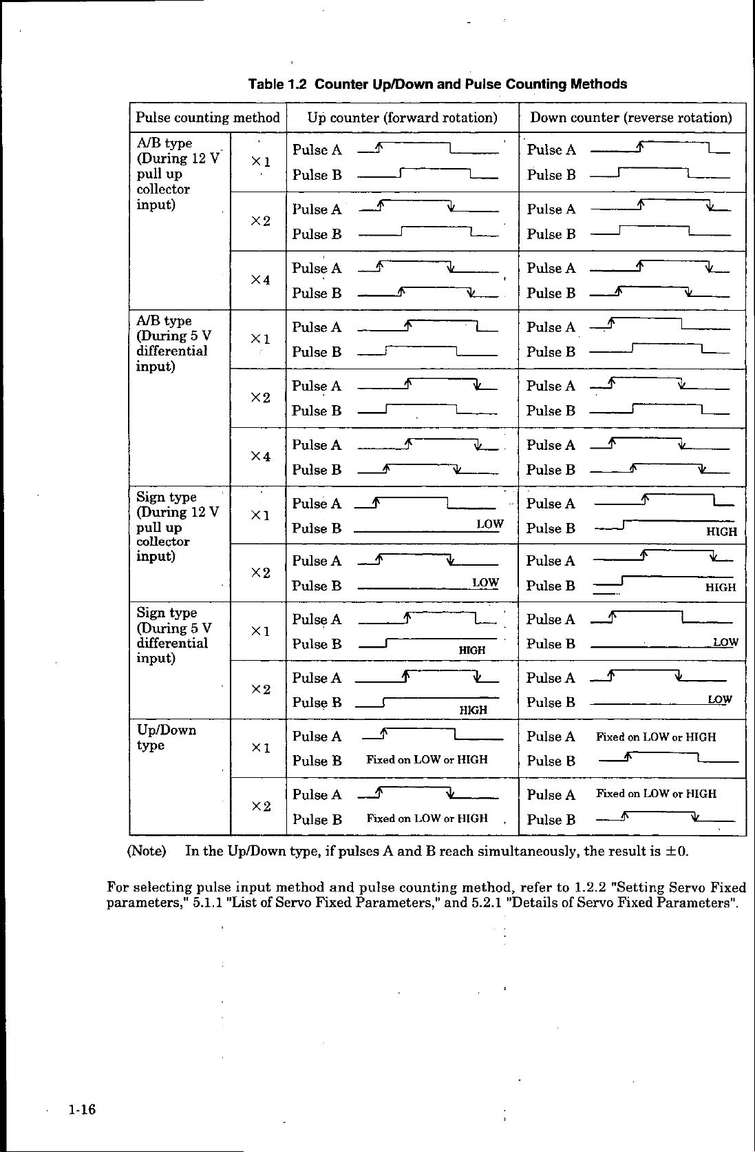
Table
1.2
Counter
Up/Down
and
Pulse
Counting
Methods
counting
Pulse
A/B
type
(During
pull
up
collector
input)
A/B
type
(During
differential
input)
type
Sign
(During
pull
up
collector
input)
12
5
12
V
V
V
method
XI
X2
X4
XI
X2
X4
XI
X2
Up
Pulse
Pulse
Pulse
Pulse
Pulse
Pulse
Pulse
Pulse
Pulse
Pulse
Pulse
Pulse
Pulse
Pulse
Pulse
Pulse
counter
A
—
B
A
—
B
A
—
B
A
B
A
B
A
B
_
A
B
A
—
B
(forward
F
S
$
J
$
5
f
f
jf
rotation)
l
1L
1L
LOW
LOW
Down
Pulse
Pulse
Pulse
Pulse
Pulse
Pulse
Pulse
Pulse
Pulse
Pulse
Pulse
Pulse
Pulse
Pulse
Pulse
Pulse
counter
A
B
A
B
A
B
A
—
B
-
A
—
B
-
A
—
B
A
B
A
B
-ÿr
f
(reverse
jf
S
JF
$
rotation)
_
h
"\k
1
HIGH
HIGH
Sign
type
(During
differential
input)
Up/Down
type
(Note)
selecting
For
parameters,"
5
In
V
the
pulse
5.1.1
XI
X
2
XI
X2
Up/Down
input
"List
of
Pulse
Pulse
Pulse
Pulse
Pulse
Pulse
Pulse
Pulse
type,
method
Servo
A
B
A
B
A
B
A
B
pulses
if
and
Fixed
I
J
Fixed
—
Fixed
pulse
Parameters,"
f
A
LOW
on
LOW
on
and
B
counting
HIGH
HIGH
or
HIGH
HIGH
or
simultaneously,
reach
method,
and
5.2.1
Pulse
Pulse
Pulse
Pulse
Pulse
Pulse
Pulse
,
Pulse
refer
"Details
to
A
B
A
B
A
B
A
B
of
—
-
—
——
Fixed
Fixed
the
1.2.2
Servo
f
f
on
on
result
"Setting
Fixed
1L
LOW
or
HIGH
1
LOW
HIGH
or
±
is
0.
Servo
Parameters".
LOW
LOW
Fixed
1-16
Page 26
OVERVIEW
1.
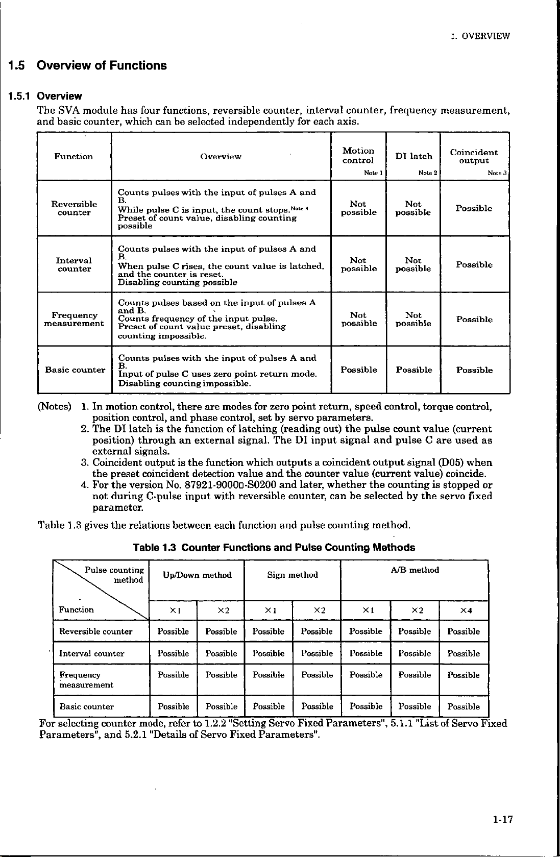
Overview
Overview
The
SVA
and
basic
Function
Reversible
counter
Interval
counter
Frequency
measurement
Basic
counter
Functions
of
module
counter,
four
has
which
Counts
B.
While
Preset
possible
Counts
B.
When
and
the
Disabling
Counts
and
B.
Counts
Preset
counting
Counts
B.
Input
Disabling
functions,
can
pulses
pulse
of
count
pulses
pulse
counter
counting
pulses
frequency
of
count
impossible.
pulses
pulse
of
counting
be
selected
Overview
the
with
input,
C
is
value,
the
with
rises,
C
is
reset.
possible
basedonthe
of
value
with
the
C
uses
impossible.
reversible
independently
input
the
count
disabling
input
the
count
inputofpulses
'
input
the
preset,
zero
disabling
input
point
pulses
of
counting
pulses
of
value
pulse.
pulses
of
return
counter,
A
N°"
stops.
A
latched,
is
A
interval
for
and
4
and
and
mode.
each
A
counter,
axis.
Motion
control
Not
possible
Not
possible
Not
possible
Possible
Note
frequency
DI
1
Not
possible
Not
possible
Not
possible
Possible
latch
Note
measurement,
Coincident
output
2
Possible
Possible
Possible
Possible
Note
3
(Notes)
Table
Function
Reversible
Interval
Frequency
measurement
1.
motion
In
position
2.
TheDIlatchisthe
position)
external
3.
Coincident
the
preset
4.
For
the
during
not
parameter.
gives
Pulse
\
counter
the
counting
method
counter
1.3
control,
control,
through
signals.
output
coincident
version
C-pulse
relations
1.3
Table
Possible
Possible
Possible
there
and
function
an
is
phase
the
modes
are
control,
external
function
of
detection
87921-9000D-S0200
No.
input
with
between
Counter
Up/Down
XI
each
Functions
method
X2
Possible
Possible
Possible
for
zero
by
set
latching
signal.
value
which
The
outputs
and
reversible
function
and
Sign
XI
Possible
Possible
Possible
point
servo
(reading
DI
the
counter
later,
and
counter,
pulse
and
Pulse
method
Possible
Possible
Possible
return,
parameters.
out)
the
signal
input
coincident
a
value
whether
be
can
counting
Counting
X2
Possible
Possible Possible
Possible Possible
speed
pulse
and
output
(current
the
selected
method.
Methods
XI
control,
count
pulse
signal
counting
by
A/B
method
X2
Possible
torque
value
C
value)
is
the
control,
(current
are
used
(D05)
coincide.
stopped
servo
X4
Possible
Possible
Possible
as
when
or
fixed
Basic
counter
selecting
For
Parameters",
counter
5.2.1
and
Possible
mode,
"Details
refer
to
of
Possible
1.2.2
Servo
Possible
"Setting
Fixed
Possible
Fixed
Servo
Parameters".
Possible
Parameters",
Possible
5.1.1
"List
Possible
of
Servo
Fixed
1-17
Page 27
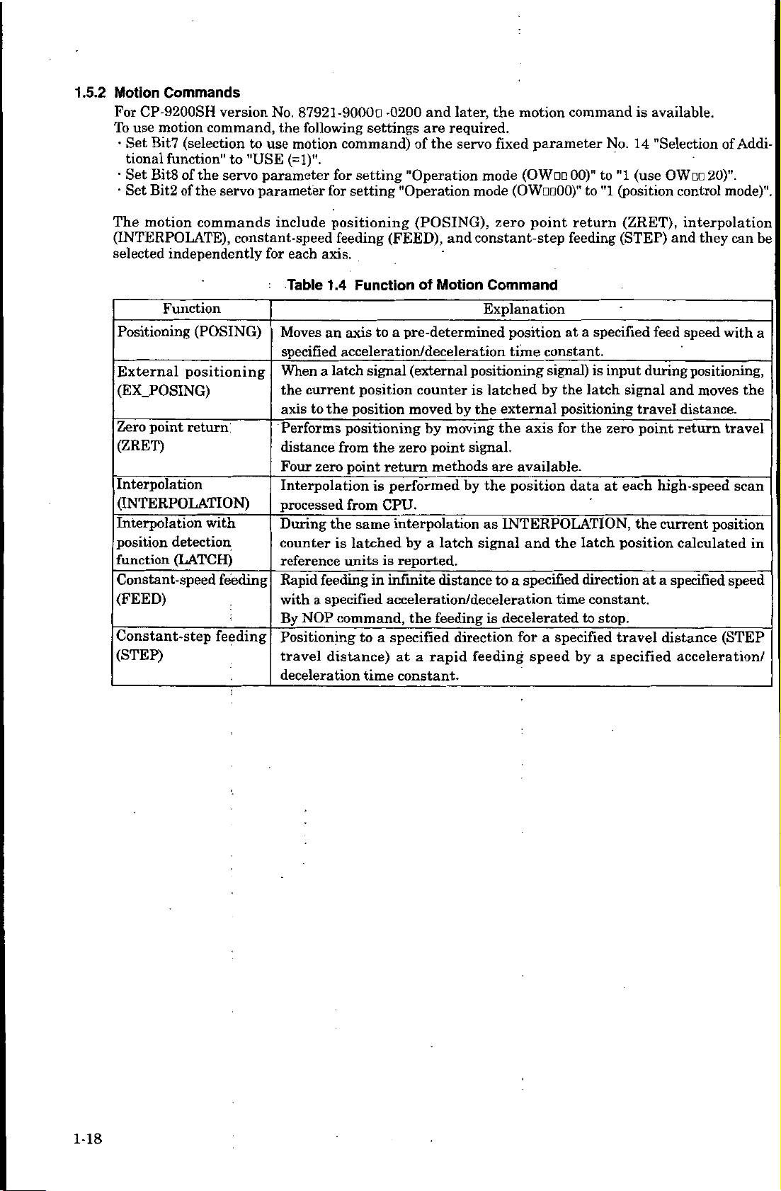
1.5.2
Motion
For
CP-9200SH
To
•
use
Set
motion
Bit7
tional
Set
Bit8
Set
Bit2
Commands
version
command,
(selection
function"
of
of
the
the
to
servo
servo
No.
the
to
use
"USE
parameter
parameter
87921
following
motion
(=1)".
-9000a
settings
command)
setting
for
setting
for
and
-0200
are
of
"Operation
"Operation
later,
required.
servo
the
the
fixed
mode
mode
motion
(OWm
(OWaoOO)"
command
parameter
00)"
to
No.
to
"1
(position
"1
available.
is
14
"Selection
(use
OW
20)".
control
Addi¬
of
mode)".
The
motion
commands
(INTERPOLATE),
selected
independently
Function
Positioning
External
(EX.POSING)
point
Zero
(ZRET)
Interpolation
(POSING)
positioning
return
(INTERPOLATION)
Interpolation
position
function
Constant-speed
(FEED)
Constant-step
(STEP)
with
detection
(LATCH)
feeding
feeding
include
constant-speed
for
each
axis.
Table
Moves
specified
When
a
the
current
to
axis
Performs
distance
Four
zero
Interpolation
processed
During
counter
reference
feeding
Rapid
a
with
By
NOP
Positioning
travel
deceleration
(FEED),
to
a
(POSING),
and
Motion
of
pre
-determined
positioning
feeding
Function
1.4
axis
an
acceleration/deceleration
signal
latch
position
position
the
positioning
from
point
from
the
same
is
latched
units
specified
command,
to
distance)
time
(external
counter
moved
the
zero
return
performed
is
CPU.
by
by
moving
point
methods
_
by
interpolation
by
latch
a
reported.
is
infinite
in
distance
acceleration/deceleration
feeding
the
specified
a
at
constant.
a
direction
rapid
point
zero
constant-step
Command
Explanation
position
time
constant.
positioning
is
latched
external
the
the
signal)
by
axis
signal.
available.
are
position
the
INTERPOLATION,
as
signal
feeding
and
specified
a
to
is
decelerated
for
speed
a
return
feeding
specified
a
at
_
input
is
the
latch
positioning
for
the
_
at
data
__
latch
the
direction
time
constant.
stop.
to
specified
by
a
(ZRET),
(STEP)
during
signal
travel
point
zero
each
_
the
position
at
_
travel
specified
interpolation
and
they
speed
feed
positioning,
and
moves
distance.
return
high-speed
current
calculated
a
specified
distance
acceleration/
can
with
the
travel
scan
position
in
speed
(STEP
be
a
1-18
Page 28

OVERVIEW
1.
1.5.3
Types
of
Acceleration/Deceleration
Acceleration/deceleration
acceleration/deceleration,
exponential
For
Exponential
Type
acceleration/deceleration
of
acceleration/
deceleration
Linear
acceleration/
deceleration
S-curve
acceleration/
deceleration
(travel
average)
be
can
and
basically
exponential
acceleration/deceleration,
is
1
.5
for
for
Types
Table
Concerned
parameters
OWOD
OC
(servo
parameter
setting
acceleration")
OWOD
(servo
setting
"Linear
OD
parameter
"Linear
motion
deceleration")
OC
OWna
(servo
parameter
setting
acceleration")
OWno
(servo
setting
deceleration")
OWOD
(servo
setting
number
OBon
(servo
setting
selection")
"Linear
OD
parameter
"Linear
14
parameter
"Averaged
of
times"
to
214
parameter
"Filter
OBD0
type
for
for
for
217
for
into
classified
linear
acceleration/deceleration.
setting
possible
Set
time.
Speed
Set
of
only
of
Acceleration/Deceieration
Speei)
0
Linear
the
timetoreach
0
U
OWuO
14
Linear
(travel
"2"
bias
when
,
u
OWDDOC
acceleration
OWDOOC
acceleration
averaging
speed
the
Rated
the
rated
Rated
OWOD
acceleration/deceleration,
possible.
is
motion
commands
are
Contents
Rotation
time
motor
Rotation
Speed
Linear
speed
Speed
OWOD
OD
deceleration
for
acceleration/deceleration
\
SZ
14
time
filter)
OWm
14
Linear
for
OWODOD
"Filter
OWOD
deceleration
type
S-curve
available.
Time
time
Time
*1
14
\
Averaged
number
of
times
time
selection".
(Continued)
1-19
Page 29
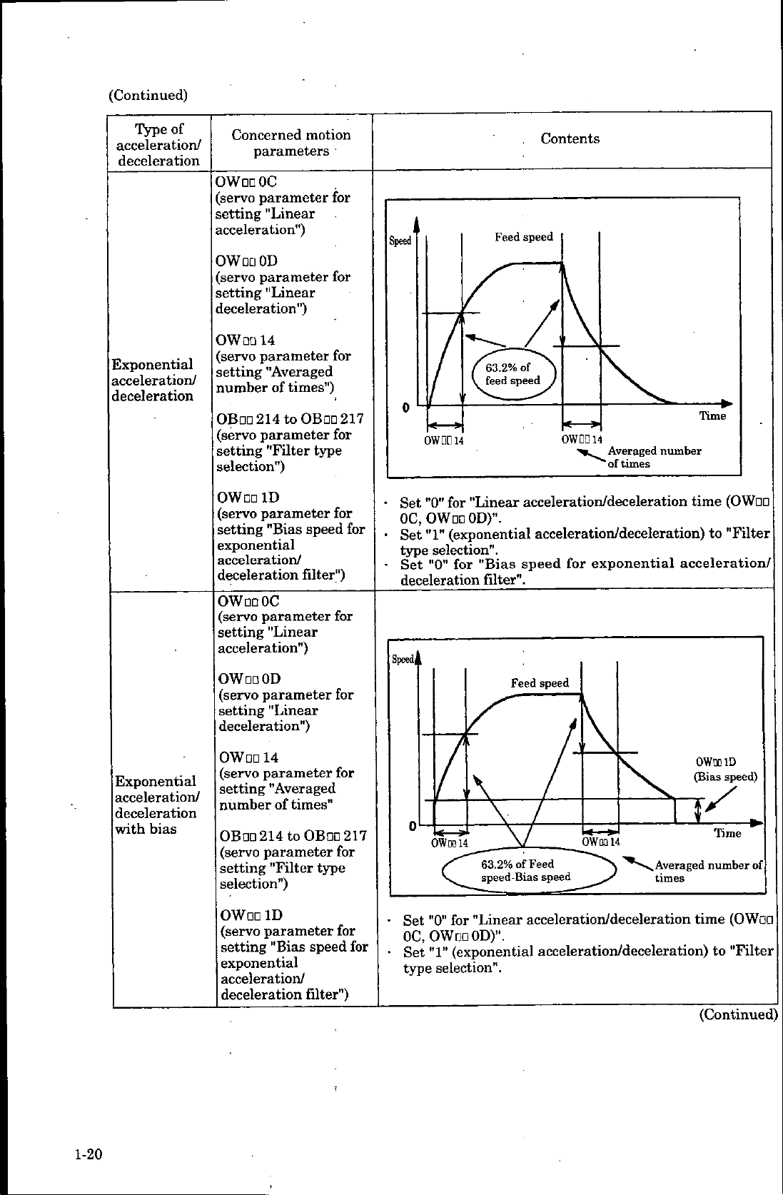
(Continued)
of
Type
acceleration/
deceleration
Concerned
parameters
OWooOC
(servo
setting
acceleration")
parameter
"Linear
OWDOOD
(servo
parameter
setting
deceleration")
"Linear
motion
for
for
Speed
Feed
Contents
speed
Exponential
acceleration/
deceleration
OWDO
(servo
setting
number
OBDD
(servo
setting
selection")
OWoo
(servo
setting
14
parameter
"Averaged
times")
of
to
214
parameter
"Filter
ID
parameter
"Bias
exponential
acceleration/
deceleration
OWDD
(servo
setting
acceleration")
OWDOOD
(servo
setting
deceleration")
OC
parameter
"Linear
parameter
"Linear
for
OBDD
for
type
speed
filter")
217
for
for
for
for
0
OWOD
•
"0"
Set
OWooOD)".
0C,
•
"1"
Set
type
selection".
"0"
Set
deceleration
Speed,
of
63.2%
speed
feed
14
"Linear
for
(exponential
"Bias
for
filter".
Feed
OWOO
14
of
number
times
acceleration/deceleration
acceleration/deceleration)
speed
speed
exponential
for
acceleration/
Time
time
(OWoo
"Filter
to
_
1-20
Exponential
acceleration/
deceleration
bias
with
OWDD
setting
14
parameter
"Averaged
times"
of
to
214
parameter
"Filter
ID
parameter
"Bias
OWDD
(servo
setting
number
OBDD
(servo
setting
selection")
(servo
exponential
acceleration/
deceleration
for
OBDD
for
type
for
speed
filter")
217
for
•
0
Set
OC,
Set
type
\
\
14
OWoo
63.2%
speed-Bias
"Linear
for
"0"
OWooOD)".
(exponential
"1"
selection".
OWDD
\
Feed
of
speed
14
Averaged
s.
times
acceleration/deceleration
acceleration/deceleration)
OWDD
(Bias
LT
time
(Continued)
ID
speed)
Time
number
(OWoo
"Filter
to
of
Page 30
1.6
Module
Hot
Swapping
1.
OVERVIEW
SVA
When
hot
are
In
any
(Note)
Not
states
swapping
The
operation
•
•
•
modules
the
modules
swapped,
case,
only
in
and
reference
During
and
torque
During
During
During
If
after
At
the
During
•
When
arrives
•
positioning
If
step
with
should
the
recommendedtoinsert
we
CP-9200SH
operations
switch
value
continues
speed
not
other
following
OFF.
with
and
be
than
are
of
servo
torque
hot
but
occurred
this
commanded.
point
point,
control
position
the
control
with
position
returning,
at
approach
at
creep
of
the
a
servo
execution,
point-to-point,
is
each
reference
zero
operation
operation
detection
zero
position
positioning
at
by
step
the
swapped,
and
will
CP-317
in
only
SVA
or
CPU
states
also
parameter
reference
controlling,
following
the
speed,
speed,
point
zero
lock
state
reference
implemented
high-speed
value
since
modules,
resulted.
be
remove
during
before
value
operation
that
pulse,
will
following
the
that
value,
when
scan,
that
at
synchronous
a
such
Special
modules
system,
dual
the
data
module
as
follows.
is
occur.
will
operation
that
operation
zero
point
result.
will
positioning
servo
a
position
the
immediately
time.
error
as
LIO
care
power
after
when
copy
between
inserted
was
performed
will
will
continue.
return
occur.
operation
state
lock
reference
a
occur
will
modules,
should
turns
SVA
a
module
or
with
continue.
operation
is
will
result.
lock
servo
CPU
and
communication
be
taken.
OFF.
is
used,
CPUs
with
removed
reference
the
will
be
executed.
executed.
value
state
is
being
will
will
goes
the
module
CPU
remains.
speed
When
it
given
result,
down.
modules,
following
hot
And
the
•
During
•
If
•
During
around
phase
operating
operation
the
control
by
the
phase
execution,
electronic
by
the
electronic
correction
the
shaft,
value
following
operation
that
cam,
at
that
will
a
servo
point.
occur.
will
lock
continue.
state
will
immediately
result
1-21
Page 31

1.7
Application
Precautions
Head
(1)
the
The
Set
(A)
following
minimum
value
a
When
additional
When
CD
The
When
©
The
When
©
The
When
©
The
When
©
The
When
©
The
precautions
values
than
more
"Selection
function")
used
minimum
used
minimum
used
minimum
used
minimum
used
minimum
used
minimum
when
high-speed
of
the
minimum
use
to
is
set
speed
in
value
in
torque
value
position
in
value
in
phase
value
zero
in
value
RUN
with
value
using
motion
to
control
high-speed
of
control
high-speed
of
control
high-speed
of
control
high-speed
of
point
of
high-speed
"OFF"
high-speed
of
a
scan
value.
command"
USE"
"NOT
mode
250
=
mode
250
=
mode
250
=
mode
250
=
return
250
=
(BitO
250
=
SVA
set
(BitO
mode
module.
time
("0")
scan
s
+
p
(Bitl
scan
s
+
p
(Bit2
scan
s
+
fi
(Bit3
scan
s
+
fi
(Bit4
scan
s
+
fi
OWDO
of
scan
s
+
fi
are
(Bit7
OW
of
set
(100
of
set
(60
of
set
(150
of
set
(100
set
(150
set
(70
as
value
OW
value
p
OW
value
OW
value
of
value
01
value
fi
follows.
fixed
of
i
00
s
fi
00
X
s
X
s
fi
00
X
s
ft
OW
DO
s
fi
"OFF")
=
X
s
parameter
"ON")
=
X
number
"ON")
=
number
00
=
number
"ON")
=
number
00
X
number
number
"ON")
"ON")
=
of
of
of
of
of
of
axes
axes
axes
axes
axes
axes
No.
in
in
in
in
in
in
14
use)
use)
use)
use)
use)
use)
"Selection
of
(B)
(Examples)
1)
2)
3)
4)
5)
When
"Selection
function")
(i)
When
("0")
©
©
©
@
When
The
minimum
When
The
minimum
When
The
minimum
When
The
minimum
When
The
minimum
is
set
"Motion
When
The
When
The
When
The
When
The
all
of
4
4
all
of
all
of
4
4
of
all
4
all
of
use
to
"USE"
to
command
used
in
minimum
used
in
minimum
used
in
minimum
used
in
minimum
axes
are
value
axes
are
value
axes
are
value
are
axes
value
are
axes
value
motion
("1")
speed
value
torque
value
position
value
phase
value
in
speed
set
high-speed
of
torque
set
in
high-speed
of
position
set
in
high-speed
of
phase
set
in
high-speed
of
set
zero
in
high-speed
of
command"
(Bit8
code"
control
of
mode
high-speed
=
control
of
mode
high-speed
=
control
high-speed
of
=
control
of
mode
high-speed
=
point
(Bit7
parameter
of
(BitO
250
250
mode
250
(Bit3
250
control
scan
control
scan
control
scan
control
scan
scan
of
scan
s
p
(Bitl
scan
s
p
(Bit2
scan
s
+
p
scan
s
p
set
set
set
set
return
set
fixed
of
set
(1
+
of
set
(170
+
of
set
(250
of
set
(180
+
mode
value
mode
value
mode
value
mode
value
control
value
parameter
for
OW
DO
value
70
p
OW
value
p
OW
value
p
OW
value
p
250
=
650
=
=250
490
-
=250
850
=
250
=
650
=
250
=
850
=
setting
00
=
X
s
00
=
X
s
00
X
number
s
00
=
X
s
s
fx
s
ft
s
ft
s
fi
s
ft
s
ft
s
ft
s
p
mode
s
p
s
p
No.
OWOD
"ON")
number
"ON")
number
"ON")
=
"ON")
number
(100
+
(60
+
(150
+
(100
+
(150
+
"Selection
14
00)
axes
of
of
axes
of
axes
of
axes
X
axes)
s
p
p
s
set
in
in
in
in
X
s
s
s
use)
4
axes)
4
X
4
axes
X
axes)
4
X
axes)
4
additional
of
to
"INVALID"
use)
use)
use)
)
ft
fi
//
is
1-22
Page 32

OVERVIEW
1.
©
©
(Examples)
1)
2)
3)
4)
5)
(ii)
When
("1")
®
©
®
When
The
minimum
When
The
minimum
When
The
minimum
When
The
minimum
When
The
minimum
When
The
minimum
When
The
minimum
"Motion
When
The
minimum
When
minimum
The
When
used
used
all
of
all
of
of
all
all
of
all
of
command
used
used
used
zero
in
value
with
value
4
axes
value
axes
4
value
axes
4
value
axes
4
value
axes
4
value
speed
in
value
in
torque
value
position
in
point
RUN
are
are
are
are
are
return
of
high-speed
"OFF"
high-speed
of
set
in
of
high-speed
set
in
high-speed
of
set
in
high-speed
of
set
in
high-speed
of
set
in
of
high-speed
(Bit8
code"
control
high-speed
of
control
high-speed
of
control
mode
250
=
(BitO
250
=
speed
torque
position
phase
point
zero
of
mode
250
=
mode
250
=
mode
(Bit4
set
scan
(220
s
p
+
of
OWon
scan
set
(200
s
p
+
control
set
scan
control
set
scan
control
set
scan
control
scan
set
return
set
scan
parameter
(BitO
of
scan
set
(180
s+
p
(Bitl
of
scan
set
(170
s
p
+
(Bit2
of
value
01
value
mode
value
mode
value
mode
value
mode
value
value
OW
value
p
OW
value
p
0
of
OW
no
s
p
"OFF")
=
s
p
=
=
=
—
=
=
=
=
control
=
=
for
setting
00
X
s
00
X
s
W
no
00
=
X
number
X
number
250
p
930
p
250
p
930
p
250
p
1250
250
pc
970
pi
mode
250
pi
1130
"ON”)
=
number
"ON")
=
number
"ON")
00
=
"ON”)
s
s
s
s
s
s
p
s
s
s
s
p
OW
of
+
+
+
+
+
of
of
of
(170
(170
(250
(180
(220
OD
axes
axes
axes
axes
00)
in
in
s
p
s
/isX4
s
pt
s
pi
is
set
use)
in
use)
in
use)
use)
X
X
X
4
X
4
axes)
4
axes)
4
axes
axes)
axes)
to
"VALID"
)
©
©
©
a)
b)
When
The
When
The
When
a)
b)
When
"Axis
selection
minimum
The
When
"Axis
selection
minimum
The
used
in
minimum
used
in
minimum
used
with
When
"Axis
selection
minimum
The
"Axis
When
selection
The
minimum
selection"
is
flag"
value
selection"
flag"
is
phase
value
point
zero
value
RUN
selection"
flag"
is
selection"
flag"
is
set
to
of
to
set
of
value
control
of
high-speed
return
high-speed
of
"OFF"
set
to
value
to
set
value
(Bit5
of
"Finite
high-speed
250
=
(Bit5
of
"Infinite
high-speed
250
=
mode
250
=
mode
250
=
(BitO
(Bit5
of
"Finite
high-speed
of
250
=
(Bit5
of
"Infinite
of
high-speed
250
=
fixed
length
s
p
fixed
length
s
p
(Bit3
scan
s
p
scan
s
p
OWoo
of
fixed
length
s
p
fixed
length
s+
p
parameter
axis"
scan
(280
+
parameter
scan
(350
+
OW
of
set
(200
+
(Bit4
set
(250
+
parameter
axis"
scan
(220
+
parameter
scan
(300
set
p
axis"
set
p
on
value
p
of
OW
value
p
01
set
p
axis"
set
p
("0")
value
X
s
("1")
value
X
s
00
X
s
X
s
"ON")
=
("0")
value
s
("1")
value
X
s
No.
number
No.
number
"ON")
=
number
00
DO
number
No.
X
number
No.
number
17
17
=
17
1
"ON")
7
"Motion
of
axes
"Motion
of
axes
of
axes
of
axes
"Motion
of
axes
"Motion
of
axes
controller
use)
in
controller
use)
in
use)
in
use)
in
controller
use)
in
controller
use)
in
function
function
function
function
1-23
Page 33

(Examples)
1)
2)
3)
b)
4)
When
The
5)
When
The
When
minimum
The.
When
minimum
The
When
a)
minimum
minimum
all
all
all
When
The
When
The
all
all
of
axes
4
value
of
axes
4
value
of
axes
4
of
all
minimum
all
of
minimum
of
axes
4
value
of
4
axes
value
4
4
are
are
are
axes
value
axes
value
are
are
set
in
high-speed
of
set
in
of
high-speed
in
set
are
set
of
set
are
of
set
in
high-speed
of
set
in
of
high-speed
speed
control
scan
to
infinite
to
control
scan
control
finite
torque
position
high-speed
high-speed
zero
control
scan
point
scan
phase
mode
set
set
length
scan
length
scan
mode
set
return
set
value
mode
value
mode
axis
set
set
value
control
value
250
=
—
970
250
=
930
—
value
axis
value=
250
=
1050
=
250
=
1250
=
ft
ft
ft
fi
250
=
1370
=
250
1450
=
ft
ft
mode
ft
ft
ft
ft
(280
(300
ft
ft
X
axes)
4
s
X
axes)
s
4
X
4
s
ft
X
s
ft
s
s
4
X
axes)
4
X
axes)
4
axes
axes
)
)
(180
s
+
s
(170
s
+
s
s
+
ft
s
ft
s
+
ft
s
ft
(200
s
+
s
(250
s
+
s
(2)
Do
(3)
Whenever
in
(4)
The
Table
Speed
Torque
point
Zero
Phase
Position
(Note)
change
not
batch),
units
1.6
Table
Control
control
control
return
control
control
Use
1=1
motion
(=valid).
Use
1=1
the
the
module
be
sure
different
are
shows
1.6
the
Units
Mode
When
motion
When
motion
reference
command
pulse
when
high-speed
configuration
to
turn
OFF
depending
for
units
for
the
using
a
command
using
not
command
unit
for
"USE
to
using
scan
the
the
position
position
%
%
%
%
a
%,
min,
pulse/min
the
zero
(=1)"
control
a
value
set
definition
power
the
on
and
Speed
mm/min,
deg/min,
position
and
the
mode
of
CPU
of
and
ON
control
speed
and
speed
reference
inch/
or
offset
motion
other
module
module
CPU
again.
mode.
references
references
Torque
%
setting
command
than
thoseinTable
during
has
in
each
in
reference
(OLoa
code
travelling.
changed
been
each
control
control
pulse
pulse
mm,
pulse
06)
when
valid/invalid
1.6.
(also
mode.
mode
Position
inch,
selecting
(OBao008)
loading
at
reference
deg,
or
to
use
to
the
”1"
1-24
Page 34

BASIC
2.
:
SPECIFICATIONS
BASIC
2
chapter,
This
module
explains
classified
SPECIFICATIONS
specifications
in
hardware
basic
and
software.
for
the
SVA
2-1
Page 35

SVA
module
include
a
reversible
independently
position
and
based
A
axes
However,
can
Primary
control,
motion
axis
on
maximum
be
can
be
mounted.
features
functions
independently
when
performs
selected
phase
and
number.
of
SVA
11-
other
of
the
counter
counter,
for
be
can
modules
motion
SVA
functions
and
interval
each
axis.
control,
which
independently
can
controlled.
modules
module
motion
or
counter,
can
motion
be
Further,
selected
be
mounted
such
are
the
as
showninTable
functions
frequency
and
functions
independently
each
for
the
on
PO-Ol
axis,
single
module
2.1,
up
for
to
include
selected
and
there
CP-9200SH.
are
used,
specifications
basic
four
axes.
measurement,
speed
control,
for
each
axis.
absolutely
is
Thus,
maximum
a
in
Counter
which
torque
Counter
no
maximum
a
of
Table
functions
can
control,
functions
restriction
of
16
modules
2.2.
be
44
Category
Motion
Counter
Pulse
counting
methods
function
function
Table
Category
Table
2.2
Primary
2.1
Position
four
Reference:
Position
Hardware
Reversible
on
Reversible
Interval
Frequency
possible
A/B
Multipulication
available)
Basic
control,
axes
detection
four
axes
counter:
method,
Hardware
Features
speed
Analog
method:
pulse
latch
counter,
counter:
and
Count
Count
measurement:
Up/Down
function
Specifications
of
the
Specifications
control,
torque
Absolute
madebyYaskawa
function:
interval
disabling,
disabling
Setting
method,
is
provided
SVA
Module
control,
encoder
point/1
1
counter,
preset
possible
detection
sign
method
or
(single,
for
SVA
Specifications
axis
and
count
units
double,
phase
and
incremental
or
frequency
value
frequencies
for
or
Module
control
encoder
measurement
possible
are
quadruple
on
is
References
Speed
reference
Positive
reference
Negative
reference
Monitor,
Speed
Torque
Run
Run
Run
Pulse
Position
Maximum
torque
input
monitor
monitor
command/Run
command
status
input
detection
(D/A
torque
pulse
12
limit
limit
(A/D
method
counting
points)
8
points)
}*4
status
3"
-
X4
x
4
speed
axes
axes
axes
Analog
•
Speed
•
Positive
•
Negative
(Note)
Each
•
Speed
•
Torque
Run
•
Run
A/B/C
Can
choose
type
select
Can
logic
S0200
reference
The
sign
also
command
status
phase
collector
(valid
and
converter.)
converter.)
(Can
up
Absolute
Yaskawa.
(during
Mpps
4
reference:
torque
torque
analog
bits
15
+
monitor
monitor
be
used
between
input
signal
a
only
for
later)
encoder
quadruple
(Can
alsobeused
sign
+15
reference:
limit
reference:
limit
output
(Can
also
±10
to
:
0
0to±10
:
a
general
as
(DO)
:
(DI)
5
differential
V
polarity,
CP-9200SH
incremental
or
as
bits
sign
range
be
V
V
DI.)
points
points
4
:
positive
sign
is
used
input
logic,
version
encoder
full
7
multiplication)
general
a
+
+
0
to
as
87921-9000O-
bits
15
bits
15
±1
general
a
and
or
made
D/A
V
1
12V
negative
by
A/D
pull
2-2
(Continued)
Page 36

(Continued)
2.
BASIC
SPECIFICATIONS
Motion
functions
Reference
Position
Position
Position
Position
Speed
reference
Speed
reference
Speed
reference
Speed
reference
Positive
reference
Negative
reference
Positive
reference
Negative
reference
Positive
reference
Negative
reference
Positive
reference
Negative
reference
Category
reference
reference
reference
reference
torque
limit
for
axis
torque
for
axis
torque
limit
for
axis
torque
for
axis
torque
limit
for
axis
torque
for
axis
torque
limit
for
axis
torque
for
axis
for
for
for
for
for
for
for
for
1
limit
1
2
limit
2
3
limit
3
4
limit
4
axis
axis
axis
axis
axis
axis
axis
axis
Specifications
1
2
3
4
1
2
3
4
Position
Speed
to
±2147483647
0
(at
0.01
Infinite
reference
Analog:
(Note)
It
at
reference:
mm/lpulse:
length
to
±327.67%
0
is
possible
100%.
Positive/Negative
Analog:
(Note)
It
at
0
to
is
100%.
possible
±327.67%
pulses
0
to
positioning
designate
to
(Default:
torque
designate
to
(Default:
±21474836
possible
also
V)
6
limit
reference
V)
3
D/A
D/A
mm)
output
output
voltage
voltage
Position
Linear
loop
acceleration/
deceleration
Auxiliary
Monitor
Speed
Speed
Speed
Speed
Torque
Torque
Torque
Torque
Counter
input
monitor
monitor
monitor
monitor
monitor
monitor
monitor
monitor
function
Reversible
Interval
Frequency
counter
gain
setting
functions
(A/D
for
for
for
for
for
for
for
for
counter
measurement
(Kp)
8
axis
axis
axis
axis
axis
axis
axis
axis
points)
1
2
3
4
1
2
3
4
999.9
to
1
Acceleration
Deceleration
Equipped
Equipped
signal
Can
Can
operation
Speed
(Note)
Torque
(Note)
Equipped
Equipped
Equipped
Setting
(1
change
change
Hz,
with
with
or
Pulse
monitor:
is
It
100%.
at
monitor:
It
is
100%.
at
with
with
with
detection
Hz,
0.1
time:
0
0
time:
zero
hardware
input
C
control
each
servo
to
0
possible
(Default:6V)
to
0
possible
(Default:
pulse
count
pulse
units
Hz
0.01
to
32.767
to
32.767
point
return
position
signal)
during
mode
parameter
±327.67%
designate
to
±327.67%
designate
to
3
count
value
count
frequencies
for
or
0.001
s
s
(for
latch
online
individually
A/D
A/D
V)
disabling
preset
disabling
Hz)
incremental
function
operation
input
input
selection
function
selection
possible
(DI
during
voltage
voltage
encoder)
input
on
line
counting
Pulse
Coincident
output
method
Can
select
method
Sign
method
Up/Down
method
A/B
available)
is
Comparison
counter
DO
value)
output
between
(Single
method
(Single,
32-bit
of
(D05)
sign
(Single
up/down
upon
method,
or
double
or
double,
coincident
Up/Down
multiplication)
multiplication)
double
or
quadruple
counter
detection.
method,
multipulication
(Set
value:
32
A/B
or
bit
2-3
Page 37

3.
EXPLANATION
OF
FUNCTIONS
AND
PROGRAMMING
USER
EXAMPLES
EXPLANATION
o
USER
°
chapter
This
operating
addition,
In
included.
and
use
methods
Refer
freely
FUNCTIONS
OF
PROGRAMMING
explains
of
simplified
these
to
the
SVA
the
examples
primary
the
SVA
module.
examples
module.
EXAMPLES
functions
of
user
programs
to
create
user
AND
and
are
programs
3-1
Page 38

3.1
Reversible
count
count
counting
current
goes
high
input
The
stopped.
•
The
The
•
The
each
•
Digital
converter)
Counter
UP
or
can
value
be
can
count
speed
scan.
(DI)
output
and
by
preset
the
by
DOWN
be
prohibited
valueisstored
and
output
(D/A
(DO)
converter)
input
by
the
the
in
servo
the
can
pulse
of
parameter
servo
hardware
be
used
is
used
A
or
B.
setting
parameter
counter
general-purpose
as
general-purpose
as
During
setting
current
inputofpulse
the
(BitCof
(Bit
B
value
DI
A/D
OWODOO
of
OWDDOO
and
and
+
(ILCD08
DO.
D/A.
the
C,
axis
axis
+
axis
+
Analog
counting
ofs).
ofs).
ofs)
input
is
with
(A/D
Counting
the
of
Pulses
Current
(Note)
register
counter
Pulse
(+)
(-)
and
B
A
C*~
count
For
CP-9200SH
stopped
rameter
When
When
Count
preset
i
Iff
l
IX
i
nl
i
|
—
Stop
12
nl
uy
|
X~
i2
version
input
by
not
or
No.14"Additional
Bit8
Bit8
"OFF",
=
"ON",
=
the
DDBH
|
n2
No.
of
the
counting
MAK7FFFFFFFH)
MIN
(80000000H)
UP
[
°3
X
8792
pulse
function
counting
X
1-9000
can
C
stopped
is
is
not
n4
n!
|
Stop|
-
I
I
"4
X~
-S0200
0
be
selected.
selection"
stopped
MAK7FFFFFFFH)
\
,tl6
i
N
(80000000H)
DOVN
°5
X
later,
and
Setting
make
can
during
even
input
during
Count
|
Stopj
"6
Ts:
this
of
of
preset
>“7
D0*N
P7
X
High-speed
whether
of
Bit8
selection:
pulse
C.
input
of
)
scan
the
the
pulse
value
set
counting
fixed
servo
C.
is
pa¬
3-2
•
The
If
1.3
•
For
counter"
"List
register
the
module
"Module
the
servo
of
Servo
number
number
Number
parameters
"Modes
of
Parameters
for
is
for
and
and
which
3.1
Fig.
1st
the
the
axis
Servo
the
used
with
dataisvalid"
for
Monitor".
Reversible
of
the
axis
number
Parameter
reversible
a
are
in
Counter
module
different,
Register
counter,
5.1.2
"List
Operation
number
change
Number".
"O"
of
Servo
1.
the
is
marked
Parameters
register
the
in
number
column
Settings"
for
referring
to
"Reversible
5.1.3
and
Page 39

EXPLANATION
3.
OF
FUNCTIONS
AND
USER
PROGRAMMING
EXAMPLES
When
<©
©
©
@
©
©
©
(Note)
as
using
Set
the
servo
Set
other
Digital
command
Digital
The
the
the
The
input
analog
positive
speed
analog
monitor
To
prevent
allow
To
To
preset
(i)
Set
(ii)
Turn
(iii)
When
"ON."
(iv)
When
count
(v)
The
Please
a
reversible
fixed
fixed
servo
output
(DO)
(OWCOOl).
(DI)
output
torque
reference
input
(IWCOOE)
counting,
counting,
count
the
the
preset
the
request
count
the
count
preset
preset
count
note
these
counter,
parameters.
parameters
be
can
informed
is
(D/A
converter)
setting
limit
setting
(A/D
as
turn
value,
data
preset
(Bit
(OWC015).
converter)
general-purpose
turn
count
count
set
to
count
count
for
completed,
is
preset
OWCOOO)
C
of
completion
functions
are
to
refer
Switch
appropriately
used
as
a
to
servo
can
(OWC002),
informed
is
disable
disable
follows.
as
preset
preset
completion
"OFF."
(Bit
invalid
the
following;
the
counter
for
mode
your
general-purpose
drive
be
A/D
(Bit
(Bit
data
(Bit
the
(Bit
of
6
when
used
status
the
converter.
B
of
B
C
count
IWCOOO)
count
(IWC001)
general-purpose
as
a
negative
the
to
OWCOOO)
of
OWCOOO)
(OLC006).
OWCOOO)
of
preset
IWCOOO)
of
6
disable
selector
machine.
DO
torque
speed
completion
turns
(Bit
by
as
monitor
"ON."
"OFF."
"ON."
turns
"OFF."
of
B
"Reversible
to
servo
to
setting
it
general-purpose
D/A
converter
limit
setting
(1WC00D)
(Bit
"ON",
OWCOOO)
(OWC003),
IWC000)
of
6
turn
is
"ON."
the
counter
DI.
and
request
drive
by
the
(=0)".
run
setting
and
torque
turns
for
3-3
Page 40

3.2
Interval
count
The
latched,
•
This
axis
•
The
•
Count
Digital
converter)
A
counter
goes
and
latched
ofs)
at
current
disabling
input
DOWN
UP
or
the
counterisreset.
(interval
data
high-speed
each
is
count
possible
is
output
and
is
used
by
the
count
scan.
the
stored
as
in
by
setting
used
be
can
general-purpose
of
pulse
are
input
value)
hardware
servo
the
general-purpose
as
A/D,
or
A
stored
counter
parameter
D/A.
At
B.
the
in
current
rising
the
hardware
value
(OWQDOO
DO.
DI,
of
counter
(ILCD08
+
Analog
pulse
Bit
input
B
+
C,
latch
axis
of
and
the
axis
count
data
ofs).
ofs).
output
value
(ILccOG
(A/D,
is
+
D/
Counting
the
of
Pulses
Interval
counter
count
Current
(+)
register|(
<->
and
A
B
Pulse
C
value
count
i
1]
OP
n
xrx
ri»2
|OOIN|!
Fig.
Of
3.2
,o4
|
Interval
MAI(7FFFFFFFH)
n5i
MIN
<80000000H)
DOlj
n
m2
Counter
16
High-speed
Ts:
Operation
MAI(7FFFFFFFH)
|7
MIN
|{
80000000
•3
X
scan
set
B)
,4
value
•
The
•
If
1.3
For
counter"
"List
register
the
module
"Module
the
of
servo
"Modes
of
Servo
number
number
Number
parameters
for
Parameters
for
is
and
and
which
the
the
Servo
used
data
Monitor".
for
axis
1st
axis
number
Parameter
the
with
is
valid"
the
of
interval
in
module
different,
are
Register
counter,
"List
5.1.2
number
change
Number".
"O"
of
Servo
1.
register
the
markedinthe
is
Parameters
number
column
for
Settings"
referring
"Interval
and
to
5.1.3
3-4
Page 41

3.
EXPLANATION
OF
FUNCTIONS
AND
USER
PROGRAMMING
EXAMPLES
When
(D
(2)
(3)
©
©
©
using
as
Set
the
servo
Set
other
Digital
output
command
Digital
The
the
the
The
monitor
To
To
input
analog
positive
speed
analog
(IWCOOE)
prevent
allow
an
interval
fixed
servo
fixed
(DO)
(OWCOOl).
(DI)
output
torque
reference
input
counting,
counting,
counter,
parameters.
parameters
can
be
is
informed
(D/A
converter)
setting
limit
setting
(A/D
converter)
general-purpose
as
turn
count
turn
count
refer
to
Switch
appropriately
used
as
a
servo
to
can
(OWC002),
(OWC015).
informed
is
disable
disable
following;
the
the
counter
for
general-purpose
drive
status
be
A/D
(Bit
used
(Bit
B
a
as
negative
the
the
to
converter.
OWCOOO)
of
B
OWCOOO)
of
mode
selector
your
machine.
DO
(1WC001)
to
setting
by
as
general-purpose
general-purpose
torque
speed
limit
monitor
"ON."
"OFF."
"Interval
to
it
D/A
converter
setting
(IWCOOD)
counter
servo
drive
DI.
by
setting
(OWC003),
and
the
(=1).”
run
and
torque
3-5
Page 42

3.3
Frequency
frequency
The
•
•
•
frequency
The
The
current
Digital
converter)
input
Measurement
is
computed
is
count
(DI)
output
and
stored
value
and
output
(D/A
basedonthe
in
is
the
detected
storedinthe
(DO)
can
converter)
sequence
frequency
hardware
used
be
is
used
pulses
of
(ILOD06
as
general-purpose
as
A
counter
general-purpose
and
axis
+
current
B.
ofs)
A/D
at
value
and
DI
and
high-speed
each
(ILOCOS
DO.
D/A.
axis
+
Analog
scan.
ofs).
input
(A/D
[Frequency
The
more
If
If
value
there
than
is
is
computed
measurement
frequency
is
computed
N-N„
(M+l)Ts+(Tn_
Ts
Nn_,,
T”_j,
M
MULT
(Note)
one
pulse,
no
Nn-2i
Nn
Tn
pulse
a
for
:
:
:
:
:
Frequency
For
is
value
measurement
No-1
principle]
as
XMULT
—
Tn)
:
High-speed
10
ms
count
from
unit:
of
measurement
high-speed
during
Current
Time
(count
Number
Frequency
input
estimated
Kn
follows.
value
set
scan
valueofthe
input
MHz=0.
(set
pulse
by
the
8
measurement
count
scan,
the
measurement
the
from
when
cycles
Nn+1
input
to
s)
125
fx
periods
the
servo
accuracy
±
previous
a
pulse
the
8
MHz
period,
cycle
Nn*2
pulse
head
without
fixed
±
=
1
X
input.
is
high-speed
each
at
the
measuring
of
pulses
input
parameter)
1
MHzXTs
8
±
ms
=
10
computation
becomes
the
scan.
period
1
80000
follows
computed
the
±0.00125%
=
above
result.
formula.
true
The
Input
Frequency
Current
count
•
•
•
register
The
the
If
1.3
"Module
For
the
"Frequency
Settings"
pulse
jpj(
value
module
servo
measurement"
and
To-l
<2
)(~Nÿ2~X
number
number
Number
parameters
5.1.3
"List
H
is
and
and
Nn-1
for
Servo
of
A
Ts
Fig.
the
the
used
"Modes
of
Servo
1%
Nn
X
3.3
axis
1st
axis
number
Parameter
the
with
for
Parameters
Nn*l
X
Frequency
the
module
of
are
Register
frequency
which
data
for
X
Measurement
number
different,
Number".
measurement,
valid"
is
Monitor".
Nn*
2
1.
change
5.1.2
in
.
X
the
Nn-2
register
"O"
"List
X
is
marked
of
number
Servo
referring
column
the
in
Parameters
to
for
3-6
Page 43

When
CD
using
Set
(=2)".
the
as
Set
a
servo
frequency
fixed
servo
other
measurement,
parameters.
fixed
parameters
3.
EXPLANATION
refer
Switch
OF
FUNCTIONS
following;
the
to
the
counter
appropriately
mode
for
AND
selector
your
machine.
PROGRAMMING
USER
"Frequency
to
EXAMPLES
measurement
©
©
©
<D
©
Digital
output
command
Digital
The
positive
speed
The
monitor
As
input
analog
torque
reference
analog
(IWCOOE)
necessary,
frequency
set
to
quadruple
frequencies
In
these
cases,
(ordinarily
where
cases
average
revolutions
(DO)
(OWCOOl).
(DI)
is
informed
output
(D/A
limit
setting
(A/D
input
as
the
set
required
is
average
multiplication
low-speed
the
at
the
detected
4).
or
2
the
However,
detection
set
be
can
setting
used
to
converter)
(OWC002),
(OWC015).
converter)
as
servo
is
general-purpose
revolutions
the
rather
than
("A/B
area
are
frequency
when
period
value).
of
Therefore,
a
general-purpose
status
drive
be
can
informed
used
negative
the
A/D
converter.
(OWC014)
response.
to
Specifically,
method
stable
not
can
average
frequency
the
because
greatly
be
revolutions
response
the
(IWC001)
as
a
torque
speed
the
when
X4")
stabilized
lengthened
is
DO
general
limit
monitor
the
of
the
of
the
are
speed
setting
by
general-purpose
as
D/A
converter
setting
(IWCOOD)
stability
when
duty
set,
the
A/B
error
setting
by
it
(high
detected
of
(average)
pulse
pulse
is
speed
it
to
servo
by
(OWC003),
and
counter
method,
of
the
average
almost
scan
frequencies
drive
DI.
setting
and
torque
the
of
the
detected
mode
detected
encoder
revolutions
equivalent
time
set
lags.
run
the
the
is
used.
to
X
3-7
Page 44

3.4
Basic
Speed
for
each
Counters
control,
torque
independently.
axis
control,
position
control,
phase
control,
and
zero
point
return
can
be
performed
3.4.1
Speed
This
function
be
also
single
following
D/A
Fig.
number
the
with
5.1.2
Speed
instruction).
converter,
3.4
Servo
speed
"List
control
®
(2)
(D
@
reference
Even
Control
freely.
set
the
shows
1.
If
Parameter
control
of
the
Set
other
Set
the
the
and
Select
Turn
When
stop
To
OFF.
used
is
S-curve
When
designated
the
set,
speed
a
the
module
have
Parameters
Servo
each
for
servo
fixed
servo
servo
linear
speed
the
the
run
the
run
using
in
speed
the
speed
rotating
for
acceleration
speed
linear
linear
acceleration
control
number
Register
circle
a
performed
is
axis
parameters.
fixed
parameters
parameters
acceleration
control
command
command
designated
the
control
control,
the
motor
and
control
acceleration
diagram.
block
the
and
Number"
"Speed
the
in
Settings"
for
Switch
appropriately
speed
for
deceleration
and
(NCON).
mode
(RUN)
turn
(RUN)
mode,
the
ON.
is
servo
the
run
desired
at
a
deceleration
is
selected,
and
deceleration
and
deceleration
The
number
axis
change
and
control"
and
the
with
the
control,
(Bit
(Bit
of
0
turned
ON,
parameters.
values
set
command
speed.
can
the
speed
register
are
register
the
column
"List
5.1.3
following
counter
for
your
suchasthe
(OWCOOC,
time
OWCOOO)
of
0
OWCOOl)
the
axis
of
a
(RUN)
Acceleration
easily
be
reference
When
time.
and
time
number
targets
different,
number.
the
"Modes
of
of
Servo
procedure.
mode
selectorto"Basic
machine.
speed
outputs
parameter
servo
and
the
and
obtained
output
is
using
average
the
the
to
1.3
refer
The
for
Parameters
reference
OWCOOD).
speed
the
can
control
speed
deceleration
a
with
servo
user
the
to
general-purpose
as
a
revolutions
axisofthe
1st
"Module
parameters
which
be
for
counter
setting
and
changed.
data
Monitor".
the
mode
Number
(OWC015),
torque
times
program
servo
to
module
is
valid"
(=3)."
(NCON)
can
(a
driver
"0."
and
used
in
Set
limit
(D
L
<Dr
L
®r<
Select
L
®
Turn
L
Q
Set
the
Set
speed
the
Speed
fixed
servo
I
the
servo
J
control
1
run
command
I
and
reference
The
boxes
]
The
boxes
parameters.
parameters.
mode
(RUN)
torque
output
with
with
limit
solid
dotted
(NCON).
ON.
lines
are
lines
J
n
J
“l
J
J
actions
are
HCQH
RUN
settings
Speed
the
the
{%)
COX
I
system
user
J
Pnear
ration
lime
performs.
makes.
accele¬
Speed
reference
linear
derete-
Time
(t)
3-8
Fig.
3.4
Speed
Control
Block
Diagram
Page 45

Servo
drive
(Can
be
General-purpose
General-purpose
General-purpose
General-purpose
Analog
Torque
Speed
drive
Servo
(SVRUNCMD)
(RUN)
Run
General-purpose
General-purpose
General-purpose
Genera
General
Sensor
limit
Torque
Negative
Positive
Parameters
Speed
j
Setting
linear
for
Setting
Setting
Run
status
latch
I
DI
for
Monitor
|
|
Current
|
Zero
the
position
point
status
as
used
monitor
monitor
monitor
command
run
_
DOO
—
-purpose
DO/Coincident
(SEN)
ON
setting
torque
limit
limit
torque
used
in
acceleration
linear
linear
(RUNSTS)
completion
position
at
offset
setting
acceleration
deceleration
I
D
monitor
setting
reference
for
for
(INVSTS)
general-purpose
DIO
DI
—
PI
DI
DI
(TFB)
(NFB)
DO—DOl
DO
DO
DO
—
setting
speed
and
signal
latch
_
Dll
—
DI2
DI3
—
D02
—
D03
—
D04
—
output-D05
D06
setting
(TLIMN)
(TUMP)
control
(NREF)
deceleration
(NACC)
time
(NDEC)
time
(DIINT)
(PINT)
detection
(PFB)
(ABSOFF)
_
time
PI)
mode
(r
««-
«-
J
|~
Speed
pattern
T
.1ÿ.
Lr
generation
PINT
i
100000
jjreaxiyj
100000
327eaxavi
PIL
_
-oo
PPB
i
Torque
Speed
31788
noooo
31781X71
110000
31708
110000
*85117
1151
I
f
monitor
monitor
X
X
I
Yl
n
Absolute
signal
Analog
limit
v|
Analog
limit
Analog
reference
Multi¬
plication
position
reception
negative
reference
D/A
16-bit
aign
(PWM)
with
positive
reference
D/A
16-bit
converter
(PWM)
lign
with
D/A
16
-bit
converter
(PWM)
with
aiftt
J
converter
speed
Absolute
encoder
torque
torque
CHS
cm
-fi
drive
Servo
x
*0
*5
O
2
>(
r
Motor;
!
---
Integrator
1
i
J
4
4
<-
Absolute
incremen
encoder
O
a
2
q
"
o
g
>
z
D
S
w
W
|
tali
O
O
•
I
l
£
O
w
16-bit
A/D
conver¬
sign
ter
16-bit
ter
signal)
-
of
with
with
A/D
conver¬
sign
Speed
1LI1F
limiter
o
HIM
sroitr
1
*
Aver*
.
aging
NNUM
(DI
latch
-
Operation
current
position
CD
Fig.
3.5
CP-9200SH
Speed
Control
Mode
Block
Diagram
H
GO
Page 46

Example
of
Speed
a
UMX)
user
(%)
NEEF
program
Speed
refe
rence
<Assumed
Motor
Feedback
output
D/A
output
D/A
The
above
Fig.
In
Speed
Linear
Linear
Positive
Negative
Positive
Negative
the
In
the
If
Parameter
For
detailsofthe
conditions>
speed
rated
resolution
pulse
value
value
servo
3.6
reference
acceleration
deceleration
torque
speed
number
limit
limiter
limiter
of
torque
speed
example
module
Register
0
100%
at
100%
at
parameters
time
time
limit
Fig.
3.6,
and
Number”
register
speed
of
torque
of
set
are
the
SERVOPACK
axis
the
and
(OWnuD),
Fig.
limit
through
number
change
refer
Speed
3.6
:
NR
FBppr
:
:6V
3
V
:
the
NREF
NACC
NDEC
TUMP
TLIMN
NLIMP
NLIMN
at
are
register
the
to
Chapter
Pattern
3000
=
2048
=
"Fixed
50%
=
sec
1
=
sec
1
=
-100%
=
100%
=
130%
=
130%
=
the
number
different,
5
r/min
ppr
parameter
(100%
1
refer
number.
"Servo
screen"
VS-866)
for
module
to
of
1.3
the
"Module
axis
Parameters".
of
the
Number
Time
(t)
CP-717.
number1is
and
used.
Servo
3-10
Page 47

3.
EXPLANATION
OF
FUNCTIONS
AND
USER
PROGRAMMING
EXAMPLES
Figs.
3.7
1-01000
1-00001
10000
h-
(10000:
10000
h
13000
h
ONBIT
000004
ffl
DEND
and
Fig.
for
3.8
are
VS-866)
examples
=>
using
of
programming
a
NACC
OWCOOC
=>
NDEC
=4
OWCOOD
NNUM
OWC014
=>
TLIMP
OWC002
TLIMN
OWC003
=>
NLIMP
=4
OWC004
NLIMN
OWCOOS
=>
N-OT
OBC0012]
P-OT
OBC0013]
language
Linear
Linear
Average
acceleration
deceleration
Positive
Negative
Positive
Negative
SB00004:
Negative
(P-OT)
speed
and
show
to
number
torque
limit
limit
torque
limiter
speed
limiter
Normally
overtravel
other
speed
time
time
rotations
of
(TLIMP)
(TLIMN)
(NLIMP)
(NLIMN)
contact
ON
(NOT),
reference
pattern
(NACC)
(NDEC)
(NNUM)
positive
for
the
Fig.
in
overtravel
driver
3.6.
example
the
In
setting
initial
parameters
user
parameter
initial
values
program
H0001
—
I
RUNPB
104
ACCEL
IB00105
I
n
IFON
1-05000
ELSE
hooooo
IEND
of
values
of
when
in
setting
Fig.
in
the
servo
the
DWG.A
screen
Fig.
the
3.7,
CP-9200SH
user
Fixed
the
parameters
initializing
and
and
saving
3.7
initial
program
Parameter
can
is
turned
them
RUNMOD
OWCOOO
=>
RUN
OBC0010
-o-l
NREF
OWC015
=>
NREF
OWC015
=>
Settings
is
created
screen
be
stored.
ON.
settings.
is
recommended.
Stored
Thus,
The
I
(DWG
in
of
this
method
Turn
Run
When
begun.
When
turned
speed
When
A01)
DWG.A
the
CP-717,
value
is
speed
command
IB00104
the
ON,
reference
IB00105
and
the
of
decelerated
deceleration
settings
by
pressing
automatically
are
same
as
setting
control
to
is
initial
"ON".
the
turned
acceleration
in
is
stop
is
the
turned
(speed
(DEC).
speed
to
time
are
initialized,
the
"Save”
set
the
method
values
driver
(RUN)
speed
ON,
reference
controlled
acceleration
OFF,
reference
but
key,
the
in
of
creating
in
the
control
(IB00105)
50%
at
(ACC)
time
the
speed
)
0%
after
servo
servo
of
in
the
a
is
is
the
.
is
the
DEND
The
user
a
example
program.
of
Fig.
3.8
is
extremely
3.8
Fig.
simplified,
Run
command
actually
but
(DWG
each
H01)
register
can
be
freely
controlled
with
3-11
Page 48

3.4.2
Torque
Control
This
function
fastening
device
are
targets
refer
The
"Modes
.
output
the
1.3
to
Servo
for
When
Parameters
Set
®
other
(2)
Set
the
(3)
Select
Turn
©
When
reference
Even
torque
mode
Note)
is
used
metal
a
to
1st
mold
torque
the
servo
axis
"Module
parameters
which
dataisvalid"
Monitor".
for
the
servo
servo
servo
the
control
speed
the
torque
the
run
the
run
using
the
in
control
(TCON)
Negative
cannot
It
for
for
control
driver.
the
module
of
Number
used
Torque
fixed
parameters.
parameters
fixed
parameters
setting
control
command
command
the
torque
control
required
is
OFF.
torque
be
used
generating
is
selected,
molding
plastic
Fig.
number
and
Servo
with
torque
5.1.2
in
control
for
(OWCOlC).
mode
(RUN)
(RUN)
designated
mode,
for
setting
limit
torque
a
as
a
specified
with
specified
the
3.9
shows
If
1.
Parameter
control
of
"List
each
for
Switch
appropriately
torque
the
control,
(TCON).
(Bit
ON.
turned
is
parameters.
servo
the
set
stopping,
turn
(OWC003)
limit.
torque
specified
a
torque
a
torque
module
the
Register
haveacircle
Parameters
Servo
is
axis
counter
your
for
suchasthe
(Bit
of
1
OWCOOl)
of
0
the
ON,
the
can
of
run
values
unrelated
pressure
reference
control
block
number
Number"
in
performed
selectorto"Basic
mode
machine.
torque
OWCOOO)
outputs
axis
parameter
servo
command
used
be
as
speed.
to
such
as
and
the
diagram.
and
the
axis
change
and
"Torque
the
Settings"
for
the
with
following
reference
torque
the
can
(RUN)
a
general-purpose
and
Select
for
an
speed
The
number
the
control"
and
counter
setting
and
changed.
be
the
this
mode
injection
control
register
are
register
columnofthe
5.1.3
"List
procedure.
(OWCOlB),
torque
the
When
torque
D/A
converter.
when
molding
reference
number
different,
number.
of
Servo
(=3)".
Set
limit
the
control
©
L
©r
L
®
L
©r-
L
r
Set
Select
Turn
|
the
Set
torque
the
Speed
'
fixed
servo
I
the
servo
1
control
-I
command
run
and
reference
|
The
boxes
~|
The
boxes
parameters.
parameters.
mode
(RUN)
T
output
with
with
Fig.
limit
solidlines
dotted
torque
(TCON).
Torque
3.9
lines
ON.
are
J
n
J
J
“I
J
actions
are
icon
tun
the
settings
Control
Torque
speed
(%>
system
the
Block
user
|
.
0
performs.
makes.
Diagram
Torque
reference
Tlme{t)
3-12
Page 49

drive
Servo
(Can
be
General-purpose
General-purpose
General-purpose
General-purpose
Analog
Torque
Speed
drive
Servo
(SVRUNCMD)
(RUN)
Run
General-purpose
General-purpose
General-purpose
General-purpose
General-purpose
Sensor
Torque
limit
|Negative
Parameters
Torque
Speed
status
Run
DHatch
1
for
Monitor
}
[Current
[Zero
position
point
used
monitor
monitor
monitor
run
ON
setting
torque
reference
limit
(RUNSTS)
completion
the
position
offset
(INVSTS)
status
general-purpose
as
PI
—
DI
—
DI
—
PI
—
(TFB)
(NFB)
command
DOO
—
DO
---
DO
—
DO
—
DO
—
DO/Coincident
(SEN)
for
setting
—
limit
torque
setting
signal
at
latch
DI
monitor
setting
DQ6
setting
control
(NLIM)
(DIINT)
(ABSOFF)
DIO
Dll
DI2
DI3
DPI
D02
DQ3
DQ4
output
(TLIMN)
(TREF)
detection
(PFB)
_
(PINT)
PI)
-DQ5
<<-
•e
<-
«f-
«ÿ
\ÿ_
|.
I
PINT
lOOQOQ
3zr«»xm
uitxioo
iilMXIVI
PIL
PFI
1
Torque
Speed
monitor
monitor
Servo
drive
w
<-
16-bit
ter
with
16-bit
tor
with
A/D
A/D
conver-
fipi
conver-
tign
1ÿ"
w
negative
Analog
reference
Multi-
plication
Absolute
reception
sifnil
limit
16-bit
with
Analog
limit
16-bit
Analog
reference
16-bit
with
*
position
J
D/A
converter
(PWM)
»ipt
positive
reference
D/A
converter
(PWM)
D/A
converter
(PWM)
sipt
327MXV2
itoooo
X
33781
110000
32761
noooo
S
1
*7
xn
->
jpour
1
latch
Operation
current
position
signal)
of
ABStlV
PULS
1
(DI
a
speed
Absolute
encoder
torque
CHS
torque
CHI
cnt
->
*
i
Integrator}ÿ
i
i
£
2
>
O
2
C
Tl
C
Z
o
o
r
•Motor*
---
t
r
Absolute
incremental}
-----
encoder
z
»
w
i
>
Z
o
c
w
&
H?
po
;
Q
t
pj
i
i
*
s
2
a
M
w
W
Fig.
CP-9200SH
3.10
Torque
Control
Block
Diagram
-0
r-
«
t»
Page 50

Example
Torque
of
(%)
TEEF
a
user
program
Torque
reference
<Assumed
Motor
Feedback
output
D/A
D/A
output
The
above
Fig.
In
Torque
Speed
Negative
the
In
the
If
Parameter
For
details
0
conditions>
speed
rated
pulse
value
value
servo
3.11
reference
limit
torque
example
module
Register
the
of
resolution
100%
at
100%
at
parameters
limit
Fig.
of
number
Number"
register
of
of
3.11,
and
the
(OWauo),
speed
torque
are
the
axis
and
Fig.
limit
through
set
VS-866
number
change
refer
3.11
:
NR
FBppr
:
:
:
TREF
NLIM
TLIMN
the
at
the
to
Torque
=
6
V
3
V
Fixed
the
=
=
2nd
are
different,
register
Chapter
3000
2048
=
50%
50%
100%
=
axis
Pattern
r/min
ppr
Parameter
of
the
refer
number.
"Servo
5
screen
module
1.3
to
of
number
"Module
Parameters".
the
CP-
used.
is
1
number
Time
7
17.
(t)
and
Servo
3-14
!
Page 51

Figs.
3.11.
3.12
and
3.13
examples
are
3.
EXPLANATIONOFFUNCTIONS
usingaprogramming
of
AND
language
USER
to
PROGRAMMING
show
torque
patterns
EXAMPLES
Fig.
in
(-05000
bioooo
ONBIT
I
SB000004
DEND
Fig.
the
3.12,
servo
of
them
In
of
screen
9200SH
initializing
saving
the
parameters
the
CP-717.
is
turned
settings.
is
user
program
hy
pressing
Initial
ON.
The
Thus,
method
values
this
recommended.
Fig.
is
created
is
NLIM
=»
OWC05C
TLIMN
OWC043
=>
Speed
Negative
EMG
o
OBC0412J
SB00004:
RDY
OBC0413
Emergency
(RDY)
3.12
the
saved
the
setting
of
Initial
DWG.A,
in
"Save"
are
same
Settings
key
after
automatically
the
as
initial
and
settings
setting
method
values
(DWG
in
limit
and
the
set
creating
of
the
(NLIM)
torque
Normally
stop
other
A02)
are
initialized.
initial
the
in
servo
limit
ON
(EMG),
reference
values
parameters
servo
a
user
parameter
(TLIMN)
contact
ready
to
Save
in
the
program
setting
to
the
the
initial
Fixed
when
in
operate
driver
values
Parameter
the
DWG.A
screen
CP-
and
and
(—
H0002
RUNPB
IB00204
U
IFON
(—05000
ELSE
(-00000
END
DEND
example
The
205
of
Fig.
3.13
simplified,
is
RUNMOD
OWC040
=>
RUN
OBccmoJ
TREF
OWC05B
=>
TREF
OWC05B
=>
3.13
Run
Fig.
but
command
actually
each
torque
Turn
Run
commandtothe
IB00204
When
begun.
When
IB00205
torque
When
torque
register
reference.
IB00205
reference.
(DWG
can
H02)
be
control
is
turned
is
turned
is
turned
controlled
ON.
driver
(RUN)
ON,
ON,
OFF,
with
torque
50%
0%
a
user
control
output
is
is
output
program.
is
as
as
3-15
Page 52

3.4.3
Position
Position
For
WhenaYaskawa
OFF,
power
For
using
Select
Control
control
position
a
the
absolute
is
turned
position
motion
whether
is
used
detector,
made
position
again.
ON
control,
command
the
motion
whenanaxis
incremental
an
absolute
is
there
are
(OWon
command
encoder
stored
two
20)
is
to
encoder
is
that
so
methods;
(Not*)
(OWoo
be
used,
the
the
20)
moved
Yaskawa
or
even
zero
method
used
is
the
to
if
point
not
or
target
made
the
return
using
not
position
power
operation
by
setting
absolute
positioning
a
to
motion
of
and
stop
encoder
is
not
necessary
command
servo
the
(servo
is
lock).
used.
device
and
the
parameter.
is
turnec
after
methoc
th(
(Note)
Position
S0200
(selection
Bit7
servo
fixed
function
(motion
Bit8
servo
parameter
(OWoo
(Note)
00)
When
selection"
setting
using
differences
The
Table.
Reference
Electric
Finite
Infinite
with
length
rotation
direction
one
rotation
Infinite
resetting
Position
Position
Position
Speed
reference
control
and
Servo
to
parameter
selection"
command
Bit7
"Operation
motion
in
3.1
Items
unit
gear
function
position
length
length
without
after
position
position
one
reference
buffer
monitor
using
later.
parameter
motion
use
_
code
setting
for
(selection
is
to
set
command.
the
operations
Differences
control
to
a
resetting
rotation
motion
No.
14
_
valid/invalid)
"Operation
use
to
Use
Not
mode
control
single
after
control,
command
command)
"Additional
mode
motion
Bit8
and
(OWon
when
Operations
in
When
(OWoa
Pulse
available
Not
Possible
Possible
possible
Not
Absolute
Not
available
unit
Pulse
reference
%
of
of
command)
(motion
00)"
is
motion
when
motion
20)
position
is
available
When
not
command
Not
(=
0
servo
of
command
to
"1"
set
command
Motion
command
is
used
not
method
for
using
(OW
(=
Use
valid)
fixed
code
(=valid),
is
used
Command
CP-9200SH
motion
20)
0)
parameter
valid/invalid)
operation
the
not
is
used
Used
and
When
Select
deg.
_
Available
Possible
Possible
Possible
Select
method
addition
Available
Specified
Select
specified
version
When
command
No.
14
of
is
are
and
motion
(OW
either
either
incremental
or
method.
unit
either
unit.
No.
87921-90000
using
not
(OWoa
Not
Use
(=
invalid)
1
"Additional
parameter
servo
performed
shown
Not
command
20)
is
no
pulse,
mm,
absolute
%
reference
motion
(-
Table
in
Used
used
20)
1)
function
without
3.1.
inch,
position
value
•
for
or
or
3-16
(Note)
Refer
3(1)
3.
to
4.
to
(6)
for
details.
Page 53

3.
EXPLANATIONOFFUNCTIONS
AND
USER
PROGRAMMING
EXAMPLES
(1)
No.
of
digits
decimal
(Notes)
Reference
The
reference
parameters.
Select
-
Select
-
function
"Minimum
Set
-
unit
and
When
-
Units
N.
below\
point
0
1
2
3
4
5
Specify
1
.
digits
of
The
2.
later.
pulse.
unit
unit
the
reference
the
reference
selection
the
motion
Table
BitO
Servo
1
1
1
1
1
1
the
below
above
For
input
unit
unit
flag".
reference
fixed
servo
command
3.2
3
of
to
fixed
Pulse
pulse
pulse
pulse
pulse
pulse
pulse
of
"No.
decimal
parameters
the
version
to
SVA
among
by
BitO
unit"
parameter
(OW
Minimum
parameter
(=
0)
digits
below
point".
are
Nos.
moduleisdetermined
mm,
of
for
the
SVA
degree
servo
module
pulse,
Bit3
to
allowed
No.18"Number
20)
is
not
used,
the
(1
Reference
No.
mm
1
0.1
mm
0.01
0.001
0.0001
0.00001
decimal
available
older
Unit
"Motion
17
(=
mm
mm
mm
mm
mm
point"
for
than
87921-9000D
reference
controller
1)
by
CP-9200SH
settings
by
(deg),
and
parameter
fixed
set
is
digits
of
reference
deg
deg
1
deg
0.1
deg
0.01
0.001
0.0001
0.00001
the
servo
version
-S0200,
inch.
by
the
below
unit
unit)
function
(=
deg
deg
deg
fixed
No.
the
of
following
the
No.
17
"Motion
explained
above
decimal
pulse.
is
selection
2)
parameter
point".
flag"
inch
1
inch
inch
0.1
0.01
inch
0.001
inch
0.0001
0.00001
No.
inch
18
87921-9000D-S0200
reference
unit
servo
fixed
controller
refernce
(=
3)
inch
"Number
always
is
and
(2)
In
Bit4
function
19
No.
rotation"
No.
20
No.
21
(Note)
Electric
The
called
The
(mm,
times,
gear
reference
"output
electric
deg,
the
machine
using
"Reference
Set
the
function
When
the
gear
function
fixed
Servo
of
No.
17
selection
"Travel
"Motor
amount
side
"Machine
The
above
For
later.
unit
unit".
gear
inch)
configuration
this
unit"
unit
is
is
parameter
"Motion
flag"
gear
side
parameters
the
is
for
is
the
the
to
electric
"Output
=
of
electric
selected
invalid.
controller
1
per
ratio"
gear
ratio"
version
the
function
output
gear
unit".
gear
pulse
to
Table
machine
are
Nos.
input
to
convert
unit.
where
function
by
the
and
3.3
Parameters
Electric
*
Travel
*
Motor
*
Machine
*
available
older
than
SVA
to
the
servo
when
When
load
can
gear
module,
the
axis
fixed
the
the
and
units
of
rotates
converts
parameters
motion
for
Electric
valid/invalid
reference
invalid.
(invalid)
”0"
to
Set
amount
When
of
this
side
When
of
this
When
this
of
for
the
parameter
gear
the
parameter
side
the
parameter
CP-9200SH
1
per
electric
ratio
electric
ratio
gear
electric
87921-9000C-S0200,
the
travel
positionorspeed
when
times
n
the
reference
shown
command
Name
unit
machine
gear
is
disabled.
gear
is
disabled.
gear
is
disabled.
version
Gear
and
(0:
is
is
is
is
the
valid,
set
set
set
set
is
Meanings
rotation
to
to
to
_
No.
electric
for
unit
not
pulse,
to
invalid
invalid
invalid
from
the
unit
in
invalid)
1:
machine
motor
to
Table.
be
to
the
(="0"),
(="0"),
(="0"),
87921-9000D
gear
function
the
reference
axis
the
3.3.
used,
electric
system
rotates
output
the
the
setting
the
setting
the
setting
-S0200
is
invalid.
unit
unit;
electric
gear
is
and
is
m
Table
3.4
shows
the
contents
and
setting
examples
of
parameters
the
in
Table
3.3.
3-17
Page 54

Servo
fixed
parameter
No.
No.
19
Table
Travel
per
rotation
3.4
Contents
Name
amount
1
machine
and
Indicates
rotation.
•
Set
reference
19
No.
•
Examples
Travel
machine
one
rotation
Setting
the
=
amount
P
[mm]
[”
360
Examples
the
load
valueofthe
unit.
Load
travel
load
per
travel
Load
£
g
=3
oa
£
of
]
Parameters
of
Contents
travel
load
amount
1
amount
travel
Reference
amount
configuration
rotation
Pitchofball
P
=
per
per
amount
load
one
unit
are
«3-
for
Electric
load
one
dividedbythe
axis
rotation
shown
below.
examples
screw
aw
Gear
axis
Initial
value
10000
•
•
Setting
unit]
.
[mm]
n
D
range
Setting
example
Where
19
amount
=
Travel
Reference
No.
unit
12
0.001
of
mm
&
T5
m
No.
per
=
mm
g
19:
1
0.001
-=
rotation
1
©
1
load
mm,
12000.
to
axis
231
—
rotation
set
as
1
1
D
[1
rotation
TCD
reference
1
=
12
=
E>
mm
(Continuted)
3-18
Page 55

(Continuted)
Servo
fixed
parameter
No.
No.
20
No.
21
Name
Motor
gear
side
ratio
Machine
gear
ratio
side
•
Sets
In
when
rotations
•
Setting
Setting
•
m
3.
EXPLANATION
gear
a
configuration
the
motor
and
range:
example
motor
rotations
of
ratio
axis
No.
3
FUNCTIONS
OF
between
where
rotates
21
to
1
65535
axis
rotations
Contents
motor
the
m
n
rotations
=
(rotations)
rotations
7
AND
and
load
times,
rotations
4
rotations
9
USER
load.
axis
set
n
rotations
PROGRAMMING
n
No.
of
times
20
load
rotates
as
=
axis
EXAMPLES
Initial
value
1
m
1
#
In
each
Setting
the
parameter
•
No.
19=
•
Axle
example
above
6
0.001
ratio=
of
machine
should
mm
mm
n
m
parameter
system,
be
=[60001
5
7
In
the
ratio
Axle
Accordingly,
for
Motor
to
get
follows:
as
above
—
=
electric
m
"reference
configuration
3
n
=
m
7
No.20
set
as
(A)
where
7
rotations
5
rotations
n
Pitch
P
unit"
by
4
9
21
21,
=
ball
a
ball
of
mm/rotation
6
=
"output
=
the
4
No.21
screw
following
is
screw
unit"
4.
=
installed
0.001
=
axle
ratio;
mm,
the
set
value
of
•
No.20=p7]
•
No.2l=H]
3-19
Page 56

#
Setting
example
of
parameter
for
electric
gear
(B)
where
rotating
a
load
installed
is
the
In
parameter
•No.
19=
•
Axle
•
No.20=[3]
•
NO.21=GU
(3)
Axis
There
in
position
control,
for
without
The
the
However,
"Finite
above
should
360°
0.1°
ratio=
selection
are
the
section
belt
axis
servo
length
machine
i
n
1
—
m
two
between
control
there
are
conveyor
resetting
selection
fixed
when
system,toget
be
follows:
as
=[3600]
10
=
30
of
types
where
the
two
methods;
and
the
the
count
istoselect
parameter
motion
(=
axis"
Motor
i
"reference
1
3
position
specified
control;
positions
rotationismade
method
a
other
method
after
one
which
"Motion
No.17
command
0).
m
30
rotations
10
unit"
finite
such
only
where
where
rotation.
position
controller
(OWOD20)
rotations
n
Rotating
360°
length
as
in
the
the
control
is
not
/rotation
"output
=
position
for
a
single
a
count
rotation
to
function
used,
load
unit"
control
reciprocating
direction.
is
reset
made
is
be
used.
Set
selection
the
axis
0.1°
=
where
motion,
For
every
0
to
simply
the
selection
,
infinite
axis
flag".
the
set
control
and
one
a
in
selection
is
value
is
made
infinite
length
rotation
single
by
invalid.
of
each
only
length
position
such
as
direction
Bit5
of
Set
to
Finite
length
Infinite
simply
in
Infinite
rotation
parameter
(Note)
The
For
length
single
a
length
(set
No.22
above
the
Type
position
position
direction
position
the
reset
"Reset
parameters
version
of
Position
control
control
control
position
position
Nos.
Table
without
are
older
3.5
Control
where
rotation
resetting
with
by
the
of
infinite
available
8792
than
Setting
each
resetting
motion
length
for
CP-9200SH
1-9000
Axis
for
made
is
rotation
every
fixed
axis").
-S0200,
Selection
Finite
Finite
Infinite
version
is
fixed
it
Setting
length
length
length
No.
87921-9000aa-S0200
to
for
(=
axis
(=
axis
axis
infinite
Axis
0)
0)
(=
length
Selection
1)
axis
and
(=
later.
0).
3-20
Page 57

(4)
Position
There
are
reference
position
reference
two
types
directly
reference
to
is
stored
position
of
OLED
3.
EXPLANATIONOFFUNCTIONS
setting
designation
12
to
OLED
reference
and
indirect
12.
method;
to
AND
direct
the
set
PROGRAMMING
USER
designation
position
to
buffer
EXAMPLES
set
a
No.
position
where
a
For
to
added
For
position
When
as
Table
Type
parameter
Servo
parameter
setting
direct
O
LOO
to
indirect
motion
an
absolute
3.6
of
for
designation,
and
the
the
previous
12
designation
as
buffer
an
command
position.
shows
the
Parameter
No.
(Register
of
Bit
12
OWED
01
Biti4ofowaa
01
12
OLED
there
adding
incremental
position
to
absolute
(OWED20)
parameters
Table
No.)
Position
reference
value
selection
Position
reference
Position
reference
setting
are
the
reference
the
set
position.
concerned
3.6
Parameters
Name
absolute
value
value
position
is
not
Sets
reference.
0:
1:
Specifies
0:
type
1:
Sets
(Note)
position
method
(the
buffer
treat
used,
position
with
for
Position
designation
a
Direct
directly
Set
Specify
calculated
method
value
Indirect
Sets
In
the
absolute
Absolute
Set
an
Adding
the
Set
added
OLtE
(Note)
position
a
The
on
value
and
OWED
reference
to
set
previous
No.,
treat
position
the
Contents
designation
a
whether
by
by
or
method
designation
position
a
specified
position
position
a
position
absolute
incremental
of
value
the
to
OLED
12.
When
(indirect
is
it
invalid.
data.
data
to
the
settings
selection
position
01)
method
value
the
value
the
reference
control.
Reference
method
position
position
the
the
absolute
adding
the
at
Bitl4
buffer
position
beforehand.
data
type.
method
position
value
the
present
previous
12
position
the
designation)
be
set
of
(Bitl2
differs
position
reference
to
the
of
of
OLED
position
of
data
to
incremental
of
OWED
to
No.
buffer,
to
OLED
method
travel
is
depending
of
type
set
an
present
12)
that
value
position
OLED
data
position
01
OLlXI
store
12.
value
value
buffer
selected,
reference
OWED
(Bitl4
absolute
travel
to
OLD
is
stored
set
to
Initial
12.
is
12.
an
to
01)
of
position
value
12.
the
in
OLED12
value
(Note)
0
<No‘«>
0
0
(Note)
The
For
above
the
version
parameters
Nos.
are
older
available
than
87921-9000D
for
CP-9200SH
version
-S0200,
No.
87921-9000OO-S0200
is
fixed
it
to
infinite
length
axis
and
(=
later.
0).
3-21
Page 58

Table
3.7
Position
Reference
Value
Selection
Position
selection
01)
10
(Direct
1
(In
direct
(Note)
If
reference
For
reference
(Bitl2
of
designation)
designation)
is
set
it
to
”1"
Set
by
value
shall
adding
value
example,
simply
be
value
OW[j
(adding
"1"
to
position
the
the
(OLDD
order
in
incremented.
Position
(Bitl4
type
01)
0
(Absolute
method)
1
(Adding
method)
value
(Note)
0
incremental
reference
present
12)
move
to
reference
of
OWOD
position
incremental
type
amount
travel
newly
set
and
continuously
Sets
(Ex.)
Sets
value)
OLno
amount
(Ex.)
When
travel
Sets
In
position
value
infinite
for
this
absolute
an
12
OLno
OLm
the
—
*-
12
value
added
Previous
12
previous
the
amount
<-
12
OLDD
position
a
specified
the
beforehand.
method),
length
(incremental
value
to
direction,
one
to
Position
position.
1000
2000
of
the
the
to
500,
=
1000
buffer
position
setting
a
axis.
travel
position
the
reference
present
previous
OLOD
OLOD
12
500
=
+
No.
buffer
_
parameter
Calculate
amount)
position
the
(OLon
travel
amount
value
12
Incremental
+
1000
=
1500
No.,
error
the
the
to
reference
reference
12)
OLno
of
and
store
occurs.
position
previous
(OLOO
(incremental
12.
travel
the
present
absolute
an
reference
position
12).
12)
(OLDO
is
What
The
By
equivalent
The
This
(Note)
The
Therefore,
Position
position
specifying
to
position
function
data
in
be
Preparation
Prepare
the
Name
Position
access
Position
written-in
Motion
control
(MCMDCTRL)
buffer
No.
buffer
data
command
flag
data
a
"buffer
the
buffer
is
the
sure
of
position
Buffer?
group
No."
operation
has
available
position
set
to
position
Table
(Bitl4
by
each
a
for
when
a
capacity
only
for
buffer
data
at
buffer
by
buffer
3.8
Register
OLOD
OLDD
OBDO21E
of
OW
axis
can
position
a
for
data
command
data
CP-9200SH
by
lost
are
turning
’
I
using
Parameters
the
the
No.
38
3A
21)
DD
be
of
turning
servo
Setting
stored
in
(OLDD
with
absolute
maximum
version
power
for
-231
ON
parameters
Preparation
Range
256
to
1
to
or
0
buffer
a
12),
No.
power
the
and
231-1
1
(position
position
the
position
256
points
87921-9000o
OFF
before
Table
in
of
Position
For
For
buffer
For
No
0:
Write
1:
buffer)
buffer
entered
is
X
axes.
4
-S0200
or
master-reset
using
3.8.
setting
setting
writing-in
processing
can
position
the
Buffer
Meanings
position
of
of
data
position
inside
perform
in
program.
and
later.
to
SVA
the
of
CPU
buffer.
buffer
write-in
buffer
module.
operation
module.
Nos.
position
3-22
Page 59

Read-out
By
the
parameter
It
takes
read-out
a
position
of
servo
parameters
for
monitor.
high-speed
2
command.
buffer
Use
scans
data
in
the
to
3.
EXPLANATION
Table
parameter
the
set
3.9,
data
the
to
data
to
the
OF
in
confirm
servo
FUNCTIONS
position
the
data.
parameter
AND
buffer
for
USER
PROGRAMMING
be
can
monitor
read-out
(ILno28)
EXAMPLES
the
to
issuing
after
servo
Name
Position
access
Motion
control
buffer
No.
command
flag
(MCMDCTRL)
Position
read-out
buffer
data
Using
By
data
setting
reference
value.
Table
Name
Position
setting
(XREF)
RUN
reference
command
setting
(SVRUNCMD)
of
position
the
3.10
Table
Register
(Bitl5
servo
parameters
Parameters
Register
(Bit
3.9
Parameters
38
OLnn
21F
OBDD
OW0D21)
of
28
ILoo
buffer
OLOD
12
OBaoOlC
12
OWDD
of
No.
for
for
No.
position
Table
in
Using
01)
Reading-out
for
Setting
1
Oor
-
231
reference
3.10,
Data
Setting
1
to
to
the
of
to
1
Range
256
256
1
231-1
data
Position
Range
of
Data
For
For
No
0:
1:
Read-out
Read-out
of
position
Buffer
Set
reference.
Selection
0:
1:
Position
setting
reading-out
of
processing
data
buffer
as
Position
position
a
to
position
Use
XREF
Use
(OLnn
(OLnn
position
12)
Buffer
Meanings
position
position
position
of
can
Meanings
buffer
use
position
reference
12)
buffer
data
buffer
buffer
buffer
be
used
as
Reference
No.
for
buffer
value
data
No.
for
Nos.
position
a
position
a
for
XREF
Position
manipulator
The
current
mode
or
position
The
deceleration
to
target
the
-
Where
Deceleration
control
position,
having
after
change
position
Current
without
moves
target
the
point).
start
position
is
started
Speed
motion
in
position,
changed
position
is
executed
<
according
the
is
Target
following
the
commands
and
the
position
position
the
according
position
the
to
three
motion
deceleration
reference
where
to
deceleration
the
Current
AND
deceleration
Target
Deceleration
—
-
Travelling
to
patterns
position
start
position
the
in
deceleration
time
position
time
set
position
change
position
start
distance
position
target
according
is
started
set
value.
point
(T)
(£)
®
-
-
the
to
changing
when
so
mode
that
control
value.
Deceleration
Current
:
:
:
»Tlme
>
position
Target
position
Deceleration
Position
relation
(at
the
start
start
position
of
the
the
control
target
the
positioning
position
3-23
Page 60

Where
Current
Deceleration
manipulator
position
is
started
reaches
Target
<
according
target
the
position
the
to
position.
Current
AND
deceleration
position
time
set
Deceleration
>
value
and
completed
is
start
position
when
tht
the
In
above
case,
the
over
and
Where
The
movesinreverse
deceleration
completed
is
Current
manipulator
Speed
deceleration
start
the
when
position
decelerates
target
the
to
Speed
should
point,
manipulator
Target
2?
to
position
Deceleration
-
Target
Travel
to
target
have
started
at
decelerationisstarted
reaches
the
target
position
i
a
stop
according
according
-Target
to
position
Travel
to
target
to
the
amount
position
H
start
position
change
position
amount
point
position
®.
from
point
:
Current
©
:
Target
©
:
Deceleration
®
Time
>
—
Position
>
—
Because
the
target
position
position
manipulator
the
position
position.
the
deceleration
time
acceleration/deceleration
change
point
©
<2)
:
:
Current
Target
4
Time
position
position
set
start
change
value.
time
position
set
passed
point
Then
value.
it
Because
and
then
the
moves
target
position
the
to
target
is
behind
position.
©
©
the
current
position,
the
:
manipulator
decelerates
stop,
to
a
3-24
Page 61

3.
EXPLANATION
OF
FUNCTIONS
AND
USER
PROGRAMMING
EXAMPLES
Position
The
manipulator
position,
having
after
change
The
deceleration
the
to
•
Where
The
Where
-
or
Where
The
moves
control
the
target
changed
point).
target
position
Current
deceleration
Current
Current
manipulator
in
reverse
with
motion
moves
in
position,
the
start
position
executed
is
position
started
is
Speed
position
position
decelerates
the
to
commands
the
following
and
position
Target
<
according
Target
<
target
the
deceleration
command
the
is
according
Position
position
Target
a
to
position
two
position
to
the
to
i
©
position
according
stop
according
motion
in
patterns
start
the
where
the
deceleration
Current
AND
deceleration
Target
Deceleration
—
Travel
to
1
®
AND
Current
to
according
position
position
when
control
deceleration
time
position
time
position
change
position
start
amount
position
target
position
the
to
the
deceleration
acceleration/deceleration
to
changing
mode
started
is
set
<
value.
set
point
:
©
:
©
(3)
:
-
>
»
-
Deceleration
>
value.
Deceleration
Current
Target
Deceleration
Time
Position
the
time
relation
the
(at
the
that
so
position
position
set
control
target
the
start
start
value.
time
the
of
current
mode
position
positioning
start
position
position
position,
Then
set
value.
or
it
in
the
over
the
change
above
case,
deceleration
point,
and
Speed
deceleration
point,
start
then
moves
Speed
should
the
to
the
j
®
©
started
have
manipulator
position.
target
Target
Deceleration
j
Target
—
Travel
to
target
v
m
Wk
(gr¬
at
point
decelerates
position
change
Travel
amount
position
target
to
start
position
amount
position
d>.
ill
position
change
Because
a
to
point
©
©
®
—
stop
:
©
:
©
:
:
:
*
point
position
Current
Target
position
Deceleration
Time
Position
the
manipulator
from
position
Current
Target
position
Time
the
start
target
position
passed
position
Because
and
then
the
target
moves
position
the
to
target
behind
is
position.
Position
©
©
the
current
position,
manipulator
the
decelerates
to
a
stop,
3-25
Page 62

(5)
Position
parameters
The
monitor
showninTable
3.11
are
used
for
position
monitor.
Servo
No.
(Register
ILDD
ILDD
ILDD
ILDD
Parameter
Monitor
for
02
08
18
2E
No.)
Table
Name
Target
position
monitor
(PTG)
Position
(PFG)
Machine
system
position
(MPOS)
monitor
reference
Not*
Reference
coordinate
calculated
Not*
(POS)
3.11
coordinate
system
position
Parameters
The
calculated
monitored
Normally,
becomes
Note:
When
the
1)
-
For
set,
amount)
and
reference).
Note
set
-1).
The
feedback
reported.
Note:
When
the
1)
-
position
The
reference
the
In
machine
machine
When
ILDD
parameter.
Note:
ILDO
02.
This
parameter
"Infinite
When
each
02.
the
length
"Infinite
scan
When
Position
for
by
SVA
the
the
target
the
range
is
reported.
position
add
the
newly
that
the
in
the
range
is
reported.
that
position
lock
status,
machine
for
"Finite
positions
module
position
position
axis
selection
from
reference
present
the
to
set
position
the
range
position
selection
axis
from
SVA
machine
of
status,
lock
no
lock
takes
axis".
length
position
the
length
Monitor
Contents
of
are
data
(Infinite
0
to
travel
previous
this
reference
(reset
0
to
machine
of
(Infinite
0
to
.
module
data
function
effect
axis"
is
axis"
machine
reported.
reported
every
scan.
is
set
length
when
"infinite
amount
position
value
value
is
set
length
outputs
coordinate
this
data
is
output
is
not
when
the
selected,
reference
selected,
is
coordinate
this
to
to
"infinite
axis
(incremental
reference
to
OLOD12
(OLOD12)
of
infinite
coordinate
"infinite
to
axis
externally
system
is
updated
not
externally).
it
used,
selection
axis
target
the
is
reported
it
parameter
length
reset
length
is
not
length
length
reset
are
is
the
is
the
system
axis",
position
axis"
travel
(OLoo
(position
always
system
axis",
position
reported.
(in
same
is
set
position
this
to
same
is
12)
axis
is
and
the
as
to
of
as
3-26
(Note)
Whatisthe
The
execution
motion
of
The
parameters
These
machine
of
command.
module
SVA
machine
coordinate
point
"zero
controls
valid
are
coordinate
isacoordinate
return
(ZRET)”
positions
for
CP-9200SH
system?
of
the
on
system
motion
machine
version
is
that
command
coordinate
No.
87921-9000n
by
set
execution
"zero
or
point
system.
-S0200
of
zero
setting
and
point
(ZSET)"
later.
return
operation
mode,
Page 63

(6)
Speed
speed
The
in
reference
The
parameters
reference
reference
unit
such
or
in
the
concerned
3.
EXPLANATION
as
rapid
ratio
to
with
feed
the
speed
OP
speed,
rated
motor
reference
FUNCTIONS
approach
speed.
are
shown
AND
speed,
in
USER
and
Table
PROGRAMMING
speed
creep
3.12.
can
EXAMPLES
be
set
either
Type
Parameter
Servo
fixed
parameter
parameter
Servo
for
setting
(Notes)
Table
3.12
Parameters
of
Parameter
(Register
No.5
No.7
No.8
Bit3
ofOWOOOl
OWmOA
OWODOB
OWD015
No.
No.)
Name
Pulse
method
motor
Rated
setting
Number
feedback
motor
per
rotation
Speed
reference
value
selection
Note!
Approach
setting
speed
Creep
setting
Speed
setting
counting
speed
of
pulses
1
speed
reference
Set
Sign
0:
Sign
1:
2:
UP/DOWN
3:
UP/DOWN
4:
A/B
A/B
5:
6:
A/B
Set
(100%
Set
multiplication).
Specify
creep
0:
:
1
The
selection"
(1)
(2)
This
(Bitl3
Set
speed.
Note:
Rapid
OLOD
22
NDC,
feed
speed
2
This
(Bitl3
Setareference
1
=
(n:
According
In
In
In
In
OW0D2C
Override*""
1
The
Note:
However,
By
17
switched
speed
1.
This
parameter
Set
ratiotothe
a
This
parameter
than
2.
87921-90000
parameter
This
This
parameter
is
invalid
rated
is
available
-S0200,
is
invalid
is
available
when
motor
it
when
motion
speed
for
CP-9200SH
is
fixed
motion
CP-9200SH
for
command
(1
=
to
”1".
command
0.01%)
version
version
to
Speed
for
counting
pulse
the
method
method
method
method
number
number
setting
the
and
OLCD22
And
OWQD15
rapid
creep
_
differs
(Bitl3
"speed
reference
10"
number
of
of
of
of
"speed
speed.
0.01%
of
OWOO
to
This
parameter
(Single
(Double
(Quadruple
the
is
feed
speed
of
pulse:
mm:
deg:
inch:
the
method
method
method
the
speed).
the
speed
Use
speed.
(OWOGOB)
Use
the
and
0.01%).
unit
When
1
=
(n:
units
In
In
units
In
units
units
In
When
motor
1
=
parameter
ratio
a
selection"
parameter
of
OWOO
reference
10"
of
to
pulse:
of
of
mm:
deg:
of
inch:
of
value
digits
the
for
number
units
units
units
units
set
OVERRIDE
OVERRIDE
this
setting
Bit9
"motion
controller
valid
%
100
is
used.
is
not
OWooOA,
No.
is
not
No.
OWE
87921-9000Q-S0200
used.
87921-9000D
Reference
method
(Single
multiplication)
(Double
(Single
(Double
multiplication)
multiplication)
rotations
of
pulses
of
unit
register
the
(unit:
10"
unit
for
10"
1
=
(unit
%
=
speed.
(OWfflOB)
depending
of
OWED
reference
unit/min
digits
1
=
1=1
1=1
1
=
reference
is
valid
01)
is
set
rated
is
set
is
valid
01)
is
set
for
unit
unit/min
below
unit,
the
1
1000
=
1=1
mm/min
deg/min
1=1
1=1
inch/min
rapid
means
"override
function
invalid.
and
the
of
set
and
0B,
-S0200
Contents
and
the
multiplication)
multiplication)
multiplication)
multiplication)
when
the
motor
per
for
rapid
No.
feed
for
reference
approach
reference
to
And
on
01).
value
below
1000
mm/min
deg/min
1
inch/min
value
when
to
motor
is
to
0.
when
to
the
decimal
reference
pulses/min
feed
the
rated
the
unit
is
setting
the
selection"
decimal
pulses/min
selection"
"speed
1.
speed
invalid
"speed
0.
rapid
speed
speed
unit/min.
%
feed
point)
can
originally
indicates
valid/invalid"
selection
When
it
value.
15.
OWDO
later.
and
and
later.
multiplication
motor
1
rotation
speed,
feed
rapid
unit/min.)
(OWlOA)
motor
approach
for
the
rated
to
for
=
point)
=
reference
(1
0.01
=
"speed
when
reference
speed.
unit
are
changed
be
to
neutralize
change
to
of
servo
flag",
is
set
to
For
runs
approach
speed.
speed
"speed
0,
set
1,
set
%)
as
follows:
the
fixed
the
invalid,
the
factor.
at
the
(the
value
for
the
and
(1
0,001%))
=
speed
motor
reference
in
reference
in
%
to
value
for
the
reference
value
use.
to
the
value
set
parameter
override
the
version
speed
rated
before
speed,
rapid
speed
creep
(OWlOl)
speed
value
unit.
the
rated
selection
rapid
value
selection
action.
to
can
rapid
Nos.
and
feed
for
(1
=
feed
use.
No.
be
feed
older
"
”
3-27
Page 64

Table
3.13
shows
the
parameter
setting
examples.
Type
Parameter
Servo
parameter
Servo
parameter
setting
for
fixed
Table
of
15
22
2C
No.
No.)
OWxOl
Pulse
method
Rated
speed
Number
feedback
per
motor
rotation
Speed
value
Approach
Creep
Speed
setting
Rapid
Override
I
of
Parameter
(Register
No.
5
No.
7
No.8
Bitl3
OWmOA
OWfflOB
OWQO
OLffl
OWD0
Parameter
3.13
Name
counting
motor
setting
of
pulses
1
reference
selection
speed
speed
reference
speed
feed
Setting
No.
A/B
5
=
7
No.
=
No.
2048
8
=
Therefore,
rated
the
(1)
When
When
©
fixed
speed
speed
•
OWfflOA
•
OWffl0B
•
OWDO
•
OLffl
OWCD
When
©
fixed
speed
creep
that
•
OWm0A=180
•
OWOO
•
OW0D15=
•
OLffl
•
OWCD
(2)
When
with
rapid
at
and
•
owmoA
•
OWfflOB=
•
OWffl
•
OLOO
•
OWl
(3)
reduce
To
settings
$p6B(l,
•
OLxffl
(=
Set
1
parameter
Examples
method
3000
rpm
ppr
speed
motor
"speed
reference
is
"pulse"
parameter
rpmi
1500
150
rpm,
300
=
2457
=
150
=
1228
=
15
=
—
1500
22
=
12288
=
20=10000(100%)
is
"mm"
parameter
900
mm/min,
speed
travels
the
creep
valid)
mm/min
90
10
OB=90
—
900
22=
2C=10000(100%)
"speed
reference
above
speed
speed
=
3000(rpm)
1000
=
3000
500
=
_
1500
15
3000
5000
=
22
—
=
2C=
10000
operation
the
speed
for
2C=
5000
for
No.
17.
Contents
(quadruple
3000
=
3000
=
=
24576000
selected
setting,
approach
(rpm)
(rpm)
(invalid)
(rpm)
selected
setting,
approach
mm
per
(invalid)
parameter
fixed
1500
rpm,
150
rpm,
(rpm)
300
(10.00%)
(rpm)
150
(rpm)
(5.00%)
(rpm)
(rpm)
(50.00%)
(invalid)
(100%)
reference,
1
(50.00%)
"Override
9
Bit
multiplication)
rpm
X
2048
value
selection"
the
for
to
operate
speed
X
2048
X
2048
X
2048
the
for
to
operate
speed
in
the
machine
motor
value
selection"
approach
X
10000
x
IOOOO
X
10000
by
speed
approach
X
4
(multiplication)
ppm
with
unit,
at
rpm
300
X
(ppr)
4
X
(ppr)
4
X
(ppr)
4
with
unit,
at
180
mm/min,
configuration
1
rotation,
setting,
speed
half
with
valid"
of
is
set
the
rapid
and
-1-
-r
-5-
the
rapid
set
is
to
300
the
speed,
servo
"0".
to
above
feed
creep
1000
1000
1000
above
feed
and
to
operate
rpm,
same
creep
fixed
"1"
Initial
value
method
A/B
(Quadruple
multiplication)
3000
2048
0
0
0
0
0
100%
3-28
!
Page 65

(7)
(D
(D
Not
using
position
The
of
the
module
register
parameters
servo
"Modes
Servo
Parameters
Position
Set
the
other
Set
the
speed
as
such
gain
(OWCOlO),
motion
control
number
number
for
which
control
fixed
servo
servo
fixed
position
reference
the
linear
command
diagram
block
If
1.
referring
used
to
with
dataisvalid"
for
Monitor".
for
parameters
axis
each
parameters.
reference
setting
(OWC015).
acceleration
positioning
the
3.
EXPLANATION
is
the
module
1.3
"Module
position
5.1.2
in
is
performed
Switch
appropriately
pulse
setting
In
and
deceleration
completion
shown
number
Number
control,
"List
with
the
(OLC012)
addition,
OF
FUNCTIONS
Fig.
in
and
"<
O”
of
Servo
the
counter
your
for
set
times
range
AND
The
3.14.
the
axis
Servo
Parameter
and
is
markedinthe
Parameters
following
mode
selector
machine.
and
the
constant
servo
the
(OWCOOE).
parameter
(OWCOOC,
USER
register
number
number
column
Settings"
for
procedure.
to
"Basic
OWCOOD),
PROGRAMMING
is
for
are
different,
Register
Number".
"Position
and
5.1.3
counter
the
speed
position
movement
for
positioning
EXAMPLES
the
1st
change
control"
"List
(=3)".
Set
to
the
control,
loop
axis
the
The
of
of
(3)
Select
Turn
©
When
designated
can
(5)
When
POSCOMP
range,
for
(Dr
®
©
the
the
the
changed.
be
the
control
stopping,
Set
L
Select
Turn
positioning
run
command
run
command
servo
parameters.
axis
enters
(Bit
D
continues
turn
the
servo
Set
the
servo
position
the
run
Axis
starts
control
(RUN)
the
IWC000)
of
(Servo
the
run
fixed
parameters.
A
parameters.
A
control
command
mode
A
positioning.
mode
ON.
(RUN)
is
Even
positioning
is
turned
lock
command
(PCON).
(RUN)
ON.
(PCON)
(Bit
0
turned
during
completion
ON.
is
state
(RUN)
1
n
J
(Bit
2
OWCOOl)
of
ON,
the
positioning,
Even
entered).
the
and
PCON
F'JN
OWCOOO).
of
axis
the
range,
entering
when
When
position
Speed
Hi
performs
set
values
positioning
the
positioning
the
control
Constant
ment
the
positioning
the
mode
move¬
speed
positioning
of
a
servo
completion
control
(PCON)
by
the
parameter
signal
completion
required
is
OFF.
©
I
[I
Positioning
POSCOMP
_
_
1
]
Servo
The
boxes
boxes
The
\
<
completion
turned
lock
state
with
with
Fig.
signal
ON.
solid
dotted
3.14
lines
are
lines
Position
actions
are
P05L3.P
settings
Control
the
system
the
user
Block
yfi
Lineal
acceleration
performs.
makes.
Diagram
ci
Time
>
completion
Positioning
range
HI-
•
3-29
Page 66

CO
co
o
I
Servo
(Can
General-purpose
General-purpose
General-purpose
General-purpose
Analog
Torque
Speed
Servo
(OWCOOI)
Run
General-purpose
General-purpose
General-purpose
General-purpose
General-purpose
Sensor
Torque
Negative
Positive
Parameters
Speed
Position
Position
Feed
Positioning
Deviation
Offset
tun
Deviation
Positioning
(IB0D00D)
Speed
Run
DI
Position
|
Current
Zero
|
status
drive
used
be
as
monitor
monitor
monitor
drive
run
_
(RUN)
ON
limit
torque
torque
used
reference
reference
loop
forward
completion
error
pulse
(QWQOQO)
status
error
_
compensation
(1WDD00)
status
completion
latch
monitor
at
DI
position
offset
point
(IWLL101)
general-purpose
DI
DF---
DI
---
DI
—
(IWDOOE)
(IWDOOD)
command
DOO
—
DO
•••
DO
—
DO
--
•••
DO
DO/Coincident
(SEN)
setting
limit
limit
in
pulse
gain
gain
setting
completion
latch
-•
setting
setting
position
control
setting
setting
Betting
getting
range
setting
detection
(OI/nlE)
(IBOOOOO)
setting
signal
detection
monitor
setting
output-D05
D06
(OW0002)
(OWC015)
(0L0D12)
(OWiPOF)
(OWQQlS)
(1BQQOOB)
(IUE06)
(QLC0Q6)
PI)
DIO
Dll
DI2
DI3
DOl
D02
D03
D04
(OWQQ03)
mode
(OWcnlO)
(OWooll)
{OWfflOE)
signal
(ILOD08)
Position
<ÿ
<-
U.
|-
pattern
Deviation
judgement
3.15
Fig.
100000
umxm
100000
31701
generation
i
!
i
•
T*
OB0D21A
(*1)
O
ILGD06
(PINT)
Av«r«fW(
(mwi)
(DI
1
CP-9200SH
XT]
X
(PTGD1F)
m
latch
oo
IliDOfl
1
ILCD04
(PFB)
16-bit
converter
16-bit
converter
*
Operation
of
position
target
o
—
iimoA
(PDV)
signal)
\
'
Operation
of
current
position
Positioning
A/D
with
A/D
with
OWraii
If
IUtOl
(m>
OBCE218
{•1
K»CIUA1»S)H
PI
Control
lign
aign
OWmlO
control
Mode
OW0D37
—
-IS®
Firit
Uf
Block
Torque
(*2)
1LCC32
(PIMON)ÿ
Speed
,
0WHC4
(NUMP)
rt9?
Diagram
Speed
limiter
without
monitor
monitor
3Z7IIXT3
noDoo
*
31711
OWHC5
(NL1MN)
sumo
(ABSREV)
!L£D12
PULSE)
0
i
XTl
10000
1
iwroc
[SPDREF)
t
Absolute
signal
Using
Analog
limit
Analog
limit
HIM
110005
Multi-
plication
position
reception
*J
:Available
’2
.Available
negative
reference
16-bit
with
positive
reference
16-bit
vith
Analog
XTl
16
with
for
for
Motion
torque
D/A
converter
lign
(PWM)
torque
D/A
converter
(PWM)
sign
speed
reference
-bit
D/A
converter
lign
(PWM)
Absolute
encoder
CP-9200SH
CP-9200SH
Command
*
*
-5*
CHS
CHI
CXI
version
version
•
'
No.
No.
drive
Servo
Divider
87921-90000
87921-9000D
*
<r
-SOI
-S0120
»
.
i
__
Motor
i
_ _
i
Absolute
incremental
encoder
10
and
later
and
later
Page 67

3.
EXPLANATION
OF
FUNCTIONS
AND
PROGRAMMING
USER
EXAMPLES
Example
<Assumed
Motor
Feedback
D/A
output
D/A
output
The
above
of
user
a
Speed
conditions>
speed
rated
pulse
value
value
servo
program
(%)
NR
(100%)
NREF
v
resolution
100%
at
at
100%
parameters
(Point-to-point
/
./••
r
J'
NACC
of
speed
of
torque
are
set
.
;•
>,'•
Constant
.
v-j
;
-H
fit
;
;
Fig.
3.16
limit
through
positioning)
reference
speed
:i'''
Position
Position
:
NR
=
FBppr
:
6
V
:
V
3
:
the
movement
**
;!»•.'
reference
3000
2048
=
Fixed
Pattern
r/min
ppr
Parameter
\
NOEC
screen
of
j
:
the
(l)
Time
CP-717.
Fig.
In
Constant
Linear
Linear
Positive
Negative
Positive
Negative
Position
<Operating
The
pattern
Position
In
this
the
If
Register
For
the
3.16
movement
acceleration
deceleration
torque
speed
loop
conditions>
torque
speed
gain
limit
limiter
limiter
shown
reference:
example,
module
and
Number"
details
of
speed
time
time
limit
Fig.
in
XREF
the
SERVOPACK
axis
number
and
select
register
the
3.16
stops
10000
=
are
register
the
(OWDDDD),
NREF
NACC
NDEC
TLIMP
TLIMN
NLIMP
NLIMN
Kp
at
an
pulses
the
at
3rd
different,
number.
refer
=
=
=
=
=
=
=
50
=
absolute
axis
refer
Chapter
to
50%
sec
1
sec
1
-
100%
100%
130%
130%
position
module
of
1.3
to
(100%
10000
of
number1is
"Module
"Servo
5
VS-866)
for
pulses.
used.
Number
and
Parameters".
Servo
Parameter
3-31
Page 68

Figs.
3.17
3.16.
5000
f—
K500
ho
10000
h
hlO
hiooo
hi
~
h
(10000:
10000
h
13000
h
ONBIT
I
SB000004
and
.10000
for
3.18
are
VS-866)
examples
of
using
programming
a
NREF
OWC095
=>
KP
OWC090
KF
OWC091
=>
EOV
OWC08F
PEXT
OWC08E
=>
NACC
OWC08C
NDEC
OWC08D
NNUM
OWC094
TLIMP
OWC082
>
TL1MN
OWC083
NLIMP
OWC084
NLEMN
OWC085
->
N-OT
OBC0812
language
Constant
Position
Feed
Deviation
Positioning
Linear
Linear
Average
Positive
Negative
Positive
Negative
SB00004:
loop
forward
acceleration
deceleration
numberofrotations
torque
speed
show
to
movement
gain
gain
detection
error
completion
limit
torque
speed
Normally
limit
limit
limit
the
speed
(Kp)
(Kf)
time
time
(TLIMP)
(TLIMN)
(NLIMP)
(NLIMN)
ON
position
(NREF)
value
range
(NACC)
(NDEC)
contact
pattern
(EOV)
(PEXT)
(NNUM)
in
Fig.
DEND
In
Fig.
3.17,
valuesofthe
Parameter
CP-9200SH
initializing
and
saving
and
|—
H0004
(—0000010000
RUNPB
IB00304
DEND
the
servo
screen
turned
is
them
program
user
parameters
the
of
CP-717.
ON.
Thus,
settings.
is
The
recommended.
3.17
Fig.
is
created
pressing
by
Stored
this
method
RUNMOD
=>
XREF
=>
0LC092
P-OT
OBC0813
<3
Initial
in
the
value
the
is
same
setting
of
OWC080
RUN
OBC0810
OH
-I
Settings
A,
DWG.
"Save"
automatically
are
the
as
initial
Negative
(P-OT)
key
(DWG
and
and
settings
after
method
values
Turns
motion
Position
(Absolute
Run
When
begun,
10000.
the
turned
in
the
command
reference
commandtothe
IB00304
and
When
positioning
ON.
overtravel
reference
other
A03)
are
setting
the
the
set
in
creating
of
servo
the
position
position:
turned
is
device
the
absolute
completion
(N-OT),
initialized.
initial
servo
a
user
parameter
control
ON.
(XREF)
pulse
10000)
driver
ON,
moves
position
positive
for
the
Save
valuesinthe
parameters
program
setting
mode
without
(RUN)
position
absolute
to
10000
signal
overtravel
driver
the
initial
Fixed
when
in
DWG.A
screen
using
control
position
is
reached,
IBC080D
the
is
is
3-32
The
user
example
program.
of
Fig.
3.18
Fig.
simplified,
is
3.18
but
Run
actually
Command
each
(DWG
register
H03)
type
can
be
freely
controlled
with
a
Page 69

3.
EXPLANATION
OF
FUNCTIONS
AND
USER
PROGRAMMING
EXAMPLES
(8)
(D
©
motion
Using
(1)
Positioning
This
command
(POSING)
command
acceleration/deceleration
rapid
The
However,
reversed
feed
the
if
direction,
value.
Fig.
3.19
shows
positioning
The
register
Set
the
proper
3).
(Note)
Select
The
axis
number
Number"
The
servo
Control
Setting"
for
servo
settings
Be
sure
"Additional
invalid)
the
position
number
are
and
parameters
Mode/
and
fixed
according
to
set
of
servo
change
Positioning"
parameters
function
control
is
to
speed
position
decelerate
the
block
of
each
is
different,
5.1.3
to
Bit7
parameter
move
an
time
and
the
reference
diagram
axis
is
for
the
refer
the
register
for
used
"Mode
of
"List
of
and
your
machine.
(selection
selection"
(PCON)
mode
axis
to
constant
position
reference
value
axis
an
for
positioning.
performed
1st
axisofmodule
to
1.3
number.
positioning
which
for
Servo
Parameters
the
initial
Set
use
to
"USE"
to
setting
for
at
position
the
a
commanded
at
is
too
stop
to
follows.
as
"Module
are
data
values
the
motion
(=1)
"Operation
of
Bit2
reference
can
value
small
to
take
once
and
number
Number
marked
valid"
is
Monitor".
for
servo
of
and
mode
Bit8
counter
command)
mode
OWCOOO.
position
rapid
changed
be
the
moves
.
1
If
and
with
"O"
5.1.2
in
parameters
speed.
feed
deceleration
the
for
the
module
Servo
the
in
"List
selectionto"Basic
of
(motion
selection"
servo
fixed
command
to
a
with
during
operation.
distance
position
number
Parameter
column
of
Servo
Parameters
setting.
for
counter"
parameter
code
(=
valid).
"1"
specified
or
for
reference
the
and
Register
"Position
Make
(=
No.
14
valid/
©
If
(POSING)
®
©
©
by
During
completion
the
Set
time
Turn
Set
When
changed.
To
When
To
To
command
(Note)
position
necessary,
(OWCOOC,
the
positioning
a
a
positioning
specified
the
momentary
the
cancel
abort
When
makes
•
When
method
•
When
value
enters.
set
servo
momentary
the
momentary
the
positioning,
code.
process
the
abort.
of
the
the
the
method
servo
parameter.
positioning,
the
stop
stop,
turn
of
abort,
setting
parameters
and
to
is
reference
the
OWCOOD)
(RUN)
ON
(P0SING=1)
(POSING)
servo
stop
abortiscancelled
following
the
position
(=
0),
position
the
(=1),
reference
axis
reference
the
(OLC012)
averaged
the
(BitOofOWCOOl).
"ON".
to
the
motion
is
set
During
in
the
turn
completed,
turn
HOLD
ABORT
BUSY
movements.
restarts
axis
(Bitl
(BitO
(turning
type
type
remains
and
setting
for
number
motion
positioning,
HOLD
HOLDL
(BitO
of
of
ABORT
(Bitl4
moving
(Bitl4
stopped
rapid
the
suchasthe
of
times
command
code
command
the
(BitOofOWC021)
(Bitl
of
OWC021)
of
OWC021)
IWC015)
the
to
of
to
is
"OFF")
to
OWCOOl)
of
position
OWCOOl)
until
feed
speed
linear
(0WC014)
(OWC020).
the
code,
set
value
IWC015)
"OFF".
to
or
"ON"
turned
at
is
reference
is
set
new
a
(OLC022
OWC015).
or
acceleration/deceleration
be
to
performs
axis
of
servo
to
"ON".
turned
is
NOP
set
"ON",
and
completion
the
to
set
(OLC012).
the
to
position
used
(=
adding
command
positioning
at
a
positioning
parameter
"ON".
0)
the
to
turned
of
abort,
absolute
incremental
"OFF"
the
position
(OLC012)
be
can
motion
at
axis
©
positioning
After
IWC000)
of
the
pulse
output
completion
is
turned
"ON".
completion
(OWCOOE),
range
(Bit2
of
IWC015
the
turned
is
positioning
"ON"),
when
completion
the
signal
axis
enters
POSCOMP
in
the
(BitD
3-33
Page 70

the
the
the
the
the
the
servo
initial
position
servo
servo
motion
Set
r®
Set
setting.
l_
r
Select
L©
Set
L®
r
Turn
L©
__
*~(D
Issue
(POSING).
,
parameter
fixed
value
I
control
I
parameter
III
(RUN)
ON
I
command
of
parameter
servo
mode
setting.
for
ON
to
positioningÿ1
for
(PCON).j
1
1
starts
©
The
axis
positioning.
"1
|
J
“1
n
J
j
raw
*w
Motion
(POSDC)
rosoar
command
Speed
(%)
100%
o
Linear
-
'W,
acceleration
Rated
Rapid
time
motor
feed
speed
speed
Linear
Time
deceleration
time
Positioning
HI
(l)
completion
range
(?)
The
(POSCOMP)
positioning
turns
_
~
Q
J
completion
ON
]
_
3
The
The
Fig.
boxes
boxes
3.19
signal
_
solid
with
dotted
with
Positioning
lines
lines
actions
are
are
Block
settings
Diagram
the
system
the
user
performs.
makes.
3-34
i
Page 71

Servo
(Can
be
fipn
Oenprfll-purpnflg
Gei>?rql-purppftf
General-purpose
Analog
Torqqe
Speed
Servo
Run
General-purpose
General-purpose
General-purpose
General-purpose
Ge
pefjj-purpose
Sensor
Torque
Negative
Positive
Parameter
Rapid
Speed
Override
Position
acceleration
Liner
Liner
Liner
Offset
Run
status
Deviation
Position
Speed
Run
status
latch
DI
|
Position
[Current
point
IZero
CO
oi
drive
status
general
used
as
ftral
-purpnRp
monitor
mqnitor
monitor
drive
command
run
(RUN)
-
DO/Qyincident
(SRN1
QN
setting
limit
limit
torque
torque
limit
for
positioning
(OLm22)
speed
feed
(0Wml5)
reference
(0W[p2fl
(0LGD12)
reference
/deceleration
acceleration
lime
dncElwalinn
time
(01ml
pulse
compensation
(IWmoW
error
completion
(IWtaOO)
completion
monitor
position
offset
DI
at
monitor
setting
E)
(1B:dOOQ)
latch
(IWOOOl)
PI)
DF
DT—DTI
DI
•••
DI—DI
(IWmOE)
(IWfflOD)
(OWraOl)
POO
DO
—
•••
DO
DO
DO
—
-ÿ
DOfi
setting
(0Wcd03)
(OW[D02)
Betting
(POSING)
_
_
(OWnTjCi
fOWmODi
(IBmOOD)
signal
(0Wed18)
setting
signal
(IBCDOOB)
detection
(II/nOR)
(OLflO06)~
m
DT2
3
DPI
DQ2
D03
D04
DQ5
output
OBnOIDiSPI
9,0—
-
OBonOlE(XREFTYPE)
-
time
TWIT
r«
O0GG21
(ILnOG)
>
-
OftuOlC
TYPE)
Valid
—
o
0
I
—
OBtD002
(TOON)
Deviation
judgement
OBLD002
(PCON)
A
o
jQcooa
UTiaxan
laoaoo
S279SXIIVJ
(USE.BUF)
—
|
r
—
HU]Ofi(PFB)
q-o
—
r
Position
_1_
r—
Vs—
OftDWO
0*1150.
OBDDQIG
(RUN)
ILE06
(PINT)
9
J
-
i
Position
ros
O
O—
Z”
o->
ros
oo
buffer
,
IEb!l70
(machine
ItalTO
,
(machine
oo-
ML
(DI
latch
00
-
—
Unit
conmnaa
cwenioc)
>
o
ter
pattern
lock)
-
16~bit
ter
16-bit
lock)
A/D
with
A/D
with
"O''
signal)
Curi
“
opera
conver
sign
conver
sign
generation
!
!
"
IlZdDA
I
rent
pari
UOn
ition
3
Fig.
f.
QBnC?I4'-OBaE17
(FILTER
T«
_
i-
|
Pul*
OffmlO
0BCu3f
81
w»F
h
Ip<l
(PDV)
control
PI
3.20
Operating
Position
’
IkpM
TYPE)
(0WCD14)
cocopWikw
output
IBCE156
mci'
rÿTT
limit
?0FT
OWnjJJ
IN
<*2)j*|
*1/71-0
1
Positioning
(OWmOO)
modi
letting
mode
control
,
r*rf*t
I
(ISdll
S2)
ILGC02
(PTC)
o
iBcuno
[m.chjnÿlockj
C2)
Ibrffi
(WMON)
•
u.
iag
First
(POSING)
(QBmOQ2'
fOtiUtn
i
LUul8
(MPOS)
u
|
,
P(X)N)
Torque
Speed
Umt
ttnumon
Speed
OWaXM
(NLIMP)
Block
tTH
1B00170
(machine
3
limiter
0W[H)5
(NL1MN)
iLmi
(ABSREV)
IUD12
a
it)
IQ
Uw
(SUM)
monitor
monitor
lock)
Unit
wnferaoa
EWLUOC
SPDREF)
PULSE)
r
Diagram
wotiflB
110000
12711
110000
22741
r
Multi¬
plication
Absolute
position
Mo
t»n
toawtad
Analog
torque
Analog
limit
X
72
OWmll
Analog
XT1
110000
signal
command
O0ODOO6
-oo-
negative
limit
.
16
with
positive
reference
16-bit
s,
with
If
—
speed
reference
16-bit
with
encoder
valid
Me
reference
D/A
bit
converter
(PWM)
lign
torque
D/A
con
(PWM)
lipi
D/A
con
(PWM)
aign
Absolute
*1:
Available
*2;
Available
*3:
Available
com
bon
i
L®!H
SING
an
oo
-
—
inurouTi
_
FIO
-oo
w
<•!)
•oros
OlU
-oin
UT
O
-OFO
-OSTf
___
'
verte
Servo
drive
CII
verte;
-Integrator
for
CP-9200SH
for
CP-9200SH
for
CP-9200SH
version
version
version
No.
87921-9000O-S01
No.
87921-90001-S0120
No.
8792
1-9000O-S0200
‘[Motor
;
Absolute
*
incremental
1
encoder
10
and
later
and
later
and
later
X
§
H
o
z
o
a
Z
O
a
O
z
to
>
2
£
P3
W
W
o
O
§
£
o
w
M
to
Page 72

Example
(%)
Speed
100%
o
Linear
Fig.
of
a
'
acceleration
3.21
program
user
Rated
motor
Rapid
1
feed
Position
time
Positioning
speed
speed
)v-
Linear
(Point
\
V,
deceleration
Pattern
to
point
4
time
Tin*
positioning)
:
(t)
<Assumed
Set
the
"Example
cOperation
the
In
pattern
Position
this
In
When
1.3
For
|—
RUNPB
IFON
1-00000
the
"Module
details
H0104
10000
000004
bOOOOI
conditions>
initial
of
Servo
conditions>
example,
module
Number
the
of
values
of
Parameter
shown
in
reference:
the
1st
number
and
registers
fixed
servo
Setting".
Fig.
3.21,
OLC012
module
of
axis
and
the
Servo
(OW
RUNMOD
=4
XREF
OBCOOIO
MCMDCODE
OWC020
=>
parameter
axis
the
10000
=
number1is
number
axis
Parameter
)
be
to
OWCOOO
OLC012
RUN
I
o-l
and
at
stops
pulses
are
Register
refer
used,
servo
parameter
the
absolute
used.
different,
Number".
Chapter
to
Turns
motion
position
command
Position
(Absolute
RUN
command
Issue
POSING
command
position
change
5
reference
position:
(RUN)
setting
for
10000
register
the
"Servo
control
Parameter".
mode
"ON"
(XREF)
pulse
10000)
driver
to
(positioning)
described
as
pulses.
number
with
for
referring
using
the
5.3
in
the
motion
3-36
END
DEND
The
program.
example
in
Fig.
Fig.
3.22
3.22
Example
simplified.
is
i
Positioning
of
Actually,
IB00304
When
and
starts
10000.
When
the
10000,
IBC000D
Program
register
each
the
the
is
axis
tuned
(DWG
turned
is
axis
moves
reaches
positioning
"ON".
H03)
be
freely
can
position
ON,
the
absolute
to
the
absolute
completion
controlledinthe
control
position
position
signal
user
Page 73

(2)
External
as
Same
specified
Positioning
positioning
acceleration
3.
EXPLANATION
(EX_POSING)
(POSING),
move
/deceleration
time
OF
FUNCTIONS
an
axis
constant
the
to
a
at
USER
AND
position
PROGRAMMING
reference
commanded
rapid
position
speed.
feed
EXAMPLES
with
a
(D
During
the
position
The
If
decelerated
The
positioning
(external
Refer
for
The
axis
Number"
The
"Position
"List
the
Set
proper
3).
(Note)
moving
current
for
rapid
feed
the
set
external
external
positioning
the
to
each
axis
register
number
and
parameters
servo
Control
of
Servo
servo
fixed
settings
Be
sure
according
to
"Additional
invalid)
of
at
the
position
the
external
speed
stop
to
positioning
signal)
block
is
diagram
performed
is
number
are
different,
change
Mode/External
Parameters
parameters
set
Bit7
function
servo
parameter
speed,
feed
is
positioning
the
and
and
latched
count
positioning
once
travel
An
input.
signal).
of
as
for
the
is
refer
register
the
for
used
for
and
machine.
your
to
(selection
selection"
when
by
the
travel
position
reference
travel
moves
again
distance
exclusive
"Positioning
follows.
axis
to
of
1.3
1st
number.
external
Positioning"
Setting"
the
and
initial
Set
to
use
to
"USE”
setting
for
latch
a
latch
distance
distance
the
to
can
be
discrete
(POSING)"
module
"Module
positioning
5.1.3
values
the
counter
motion
command)
(=1)
"Operation
signal
signal,
value
too
is
target
changed
input
number
Number
"Mode
of
"List
of
and
(external
and
by
set
can
short
position.
(DI
Fig.
in
1.
are
marked
for
of
Servo
servo
mode
Bit8
mode
positioning
the
axis
parameter.
the
changed
be
for
before
input)
3.20.
the
If
and
Servo
which
Parameters
parameters
selection
of
servo
(motion
selection"
signal)
moves
from
during
deceleration,
latch
used
external
signal
a
as
number
a
is
The
module
Parameter
with
in
O
"
"
dataisvalid"
for
setting.
for
"Basic
to
fixed
parameter
command
(=
to
"1"
input,
is
the
current
operation.
the
axis
(external
signal
latch
positioning
and
Register
the
column
in
5.1.2
Monitor".
Make
counter"
No.
code
valid/
valid).
is
the
(=
14
Select
®
Set
®
the
If
necessary,
(OWCOOC,
(EX_POSING)
Turn
©
(D
Set
When
©
positioning
parameters
lb
When
To
cancel
lb
command
During
of
abort.
(Note)
position
the
position
the
external
OWCOOD)
the
servo
external
external
momentary
momentary
the
the
the
abort
code.
process
When
remains
absolute
control
reference
positioning
the
set
positioning
ON
servo
(RUN)
positioning
by
the
specified
be
stop
changed.
the
can
interruption,
positioning,
of
abort,
the
abort
stopped
position
(PCON)
mode
setting
distance
travel
parameters
averaged
and
to
"ON".
(EX_POSING=2)
(POSING)
servo
external
stop
turn
BUSY
cancelled
is
no
method
positioning,
completed,
is
HOLD
turn
ABORT
(BitO
matter
(=
Bit2
at
(OLC012)
,
(OLC024).
setting
for
the
numberoftimes
is
OWCOOl)
of
for
set
in
the
the
turn
(BitO
parameters.
HOLDL
(BitO
(Bitl
IWC015)
of
(turning
the
if
0)
adding
or
OWC021)
of
OWC021)
of
is
ABORT
position
of
OWCOOO.
rapid
such
(OWC014)
motion
motion
During
HOLD
speed
feed
linear
as
command
command
positioning,
(BitO
to
(BitlofIWC015)
to
"OFF".
to
"ON"
turned
incremental
"ON",
"OFF")
to
reference
type
value
(OLC022
or
OWC015)
acceleration/deceleration
used
be
code
code,
OWC021)
of
is
or
set
and
turned
completion
at
(Bitl4
method
at
external
(OWC020).
the
the
set
to
turned
(=
NOP
"OFF"
of
OWCOOl)
(=
axis
values
"ON".
"ON".
0)
of
abort,
1).
positioning
performs
of
the
to
completion
at
the
is
and
time
the
servo
motion
axis
set
to
©
®
the
After
positioning
IWC000)
of
When
the
code.
(Note)
The
positioning
more
code.
pulse
output
completion
is
turned
positioning
external
than
completion
range
"ON".
is
positioning
is
executed,
1
scan
(Bit2
(OWCOOE),
completed,
is
is
it
set
again
and
of
IWC015
the
cancel
the
detected
necessary
another
turned
is
positioning
external
rising
at
NOP
set
to
external
"ON"),
completion
positioning
edge.
Accordingly,
the
for
positioning
when
signal
in
motion
in
the
axis
POSCOMP
the
motion
after
command
the
motion
enters
command
external
an
code
command
in
the
(BitD
3-37
for
Page 74

(D
(D
(3)
Set
the
Set
the
setting.
Select
the
Set
servo
initial
the
servo
fixed
value
position
parameter
parameter
of
J
control
i
servo
for
parameter
(PCON).
mode
setting.
for
i
i
!
i
KW
UK
command
Motion
(SLPOSDfi)
Speed
(%)
100%
Hated
Rapid
motor
feed
speed
speed|
\
External
positioning
{
distance
travel
(4)
©
©
©
©
i
©
i
Example
(94)
Speed
100*
Turn
the
servo
the
Issue
positioning
The
axis
starts
When
a
latch
moves
distance.
The
(POSCOMP)
Cancel
(=0))
user
of
the
for
positioning
the
program
Rated
Rapid
i.
(RUN)
ON
ON
to
i
motion
(EX_POSING).
command
positioning.
I
signal
is
external
positioning
I
completion
:
ON
turns
motion
motor
command
(external
speed
jl\
.
-----
speed
feed
v
external
input,
(Issue
positioning)
External
positioning
distance
the
signal
axis
travel
NOPi
travel
i
'
I
12
Latch
(external
POSOS*>
[The
_
]
signal
positioning
boxes
The
boxes
o
Linear
acceleration
with
with
signal)
solid
dotted
time
lines
lines
m
linear
actions
are
settings
are
(t)
Time
|
deceleration
lime
jposrtowgcomptetioftTaeg
I
system
the
user
the
i
performs.
makes.
3-38
°i
Linear
signal
Latch
(external
<Assumed
Set
"Example
<Operation
In
pulses.
In
When
1.3
For
initial
the
the
pattern
this
example,
the
"Module
details
acceleration
positioning
conditions?
values
of
Servo
conditions?
shown
Position
the
module
number
Number
registers
of
the
m
time
signal)
Parameter
1st
and
linear
Fig.
of
servo
Fig.
in
reference:
axis
and
Servo
(OWDQQD)
deceleration
3.
23
fixed
Setting".
3.23,
OLC024
module
of
the
axis
Parameter
Time
1
time
External
parameter
the
axis
number
number
be
to
(t)
Positioning
and
stops
at
10000
=
is
1
are
Register
used,
refer
Pattern
parameter
servo
the
external
pulses
used.
different,
Number".
Chapter
to
Example
positioning
change
5
for
register
the
"Servo
setting
as
travel
number
Parameter".
described
distance
referring
in
5.3
10000
to
Page 75

3.
EXPLANATION
OF
FUNCTIONS
AND
USER
PROGRAMMING
EXAMPLES
I-H0104
RUNPB
304
IFON
1-0001000000
boooooioooo
SB000004
(—00002
IEND
DEND
RUNMOD
OWCOOO
=>
XREF
OLC012
=>
EXMDIST
OLC024
=>
RUN
OBCOOR3J
MCMDCODE
OWC020
=>
In
Turns
motion
Position
position
command
reference
(Absolute
External
command
RUN
an
Issue
motion
When
control
position
When
input
is
for
pulses).
When
completion
axis
positioning
ON.
IB00304
starts
a
the
external
the
case
reaches
external
command
1000000.
latch
during
that
control
"ON"
position:
positioning
to
positioning
is
and
the
signal
feeding
positioning
movement
signal
IBC000D
a
latch
the
absolute
completion
(XREF)
pulse
1000000)
travel
driver
(RUN)
turned
axis
(external
operation,
completed,
is
signal
signal
mode
with
distance
(EX_POSING)
"ON",
moves
travel
to
positioning
the
distance
the
is
turned
input,
is
not
position
IBC000D
using
(EXMDIST)
the
position
the
absolute
signal)
axis
moves
(10000
positioning
"ON".
when
1000000,
is
turned
the
as
the
the
a
example
The
program.
in
Fig.
Fig.
3.24
3.24
External
simplified.
is
Positioning
Actually,
Program
each
Example
register
can
(DWG
be
H03)
freely
controlledinthe
user
3-
39
Page 76

(3)
point
Zero
The
zero
system.
the
Since
of
machine
Generally,
point
zero
return
point
return
position
coordinate
use
the
to
area
(ZRET)
is
an
data
are
system
limit
switch
determine
operation
once
lost
after
that
origin.
the
to
return
the
power
power
the
indicates
is
is
the
an
OFF,
ON.
zero
axis
to
is
it
point
origin
the
necessary
pulse
machine
of
to
set
(C-phase
again
pulse)
coordinate
origin
the
and
the
(Notes)
1.
For
external
For
2.
For
version
are
The
In
Fig.
the
(D
®
©
®
limit
the
DI
switch
Limit
Reversed
Forward
the
zero
the
zero
No.
available.
point
zero
this
section,
3.25
shows
method.
DECl
DEC2
DECl
(Limit
(Limit
(Limit
C-phase
+
C-phase
switch
signals
signal:
rotation
rotation
point
point
87921
pulse
and
such
side
side
return
return,
-9000D
zero
block
the
switch
switch
switch
pulse
(Zero
limit
LIO-Ol
as
motion
(with
(without
(with
(Zero
point
signal
return
the
OBDDOIF
signal
limit
signal
limit
control
the
-S0200
point
diagram
point
to
mode,
motion
and
differs
return
width))
width))
width))
signal)
signal)
for
following
the
for
zero
for
zero
refer
command
later)
depending
by
using
for
zero
point
zero
point
point
3.4.5
to
and
point
C-phase
+
C-phase
+
LMT
+
servo
return:
return:
"Zero
using
the
on
the
motion
return.
(Limit
return,
parameters
zero
method
the
pulse
pulse
prepare
OBnO
OBDO
Point
method
point
command
There
(Zero
(Zero
signal
for
21C
21D
Return
(available
control
applied.
be
to
is
the
are
point
point
zero
for
user
a
setting:
Control
for
CP-9200SH
using
mode
explained.
following
signal)
signal)
return)
point
program
Mode".
4
types
to
connect
method
in
3-40
Page 77

:
Servo
(Can
Analog
Servo
Torque
Negative
Positive
Parameter
Rapid
Speed
Override
Approach
Creep
_
Zeropointjreturn
Liner
Liner
Liner
Offset
Deviation
Zero
-
_
|
Speed
Run
|pi
(Position
|
Current
Zero
|
CO
£.
status
general
as
monitor
monitor
monitor
command
run
(RUN)
—
DO/Coincident
(SEN)
ON
getting
limit
torque
limit
torque
limit
for
zero
(OLm22)
speed
(0Wcd15)
(0Wm2C)
(OW[t]A)
speed
(OWmOB)
travel
/deceleration
time
time
(OLmlE)
(lBcnOOO)
error
completion
_
_
(IWODOO)
completion
at
PI
monitor
setting
offset
(IWCDOl)
POO
setting
point
setting
latch
drive
be
used
General-purpose
General-purpose
General-purpose
General-purpose
Torque
Speed
drive
Run
General-purpose
General-purpose
General-purpose
General-purpose
General-purpose
Sensor
feed
reference
upwd
acceleration
acceleration
deaeration
pulse
return
point
compensation
status
latch
monitor
position
point
Dl)
DIO
PI
—
PI
Dll
—
DI2
Dl
—
D13
PI
-
(IWQDOE)
(IWOPOD)
(OWcnOl)
-
-
DO
DPI
D02
DO
--
D03
DO
DO
D04
---
output-DO
DQ6
-
(OWQ303)
setting
(OW{D02)
(ZRET)
return
duUnceffllÿAÿ
time
(OWmOQ
(OWmOD)
(IRni56)
status
(0WcoI8)
signal
(IEerflOB)
(ILmO(S)
detection
(IL00Q8)
(0UDQ6)
5
OBODOID
—9-o
-
3
_
I
-
(SPDTYPE)
-
Valid
OO
OBnooz
(PCON)
55
Deviation
judgment
Ct)
0BU21A
oo
-
100000
imixm
IOO0OO
327(1
zii
OO
«
OBCDOIO
(RUN)
o
OBCQ0O2
(PCON)
MY
X
1
ffl
Iftriio
(machine
OBtnOlO
(EMU)
Hm06
(PINT)
(pre;
r
lock)
'
IBrnlJO
(machine
(Dl
latch
05
ML
16-bit
ter
if
r
J
loch)
signal)
with
pattern
A/D
sign
point
Zero
J
1
Cu
operation
Fig.
ccnver
conver-
return
generation
rx-
IlfljOA
(PDV)
I
3.25
O0CE218
Zero
OWoflO
ttnAi-o
PI
control
Operating
[Position
0WaC7
<*D|Pl
Point
mode
setting
control
HCD18
(MPOS)
&
First
Return
mode
(machine
(PIMON)
lag
(OWCDOO)
(0ftrPQ2-
IBml70
lock)
1*2)
ILCC32
*
T
(ZRET)
PCON)
Torque
Speed
Speed
owaw
(NUMP)
monitor
UOD02
(PTC)
n
T
limiter
Bloch
OBmOlO
(RUN)
monitor
Target
OWaPS
(NL1MN)
ILCD10
(ABSREV)
IDnl2
(I
smaiii
lia«
II.
—
nifxn
110000
WWXT>
lioooo
positioD
-
—
atioa
iwmoc
(SPDREF)
1
f
.AUlui.
M
MJMXTr|
Multi-
plication
position
q*u
PULSE)
Diagram
-
Pulse
lioooo
signal
Motion
'"nnmnns
Analog
torque
Analog
limit
output
Analog
coramiivd
valid
negative
limit
reference
16-bit
with
ii*n
positive
reference
16-bit
D/A
with
lignfPWM)
completion
speed
Jfi-titD.'A
eign
"Tvith
Absolute
*1:
Available
*2:
Available
*3:
Available
--ÿm
--j&
D/A
converter
(PWM)
torque
convener
(PWM)
towbfQWfpm
-Oros
-OlXf
-o
IttlJtmAT*
—
—
m
-O
IPL
-OUT
-OFID
-OSIP
3
____
..
Servo
drive
-
(IKE1521
reference
converter
i0*1
Integrator
encoder!
for
CP-9200SH
for
CP-9200SH
for
CP-9200SH
version
version
version
No.
87921-9000D-S01
No.
87921-9000D-S0120
No.
87921-9000C-S0200
•|
Motor,'
Absolute/
incremental
encoder
and
later
10
and
later
and
later
W
*0
>
a
c
Z
O
5
z
3
O
>
O
£
3
O
1
i
§
§
ra
3
Page 78

DEC1
(1)
After
point
Apply
Deceleration
C-phase
+
rapid
using
this
feeding
the
limit
method
LS
pulse
with
switch
when
K
linear
the
acceleration/deceleration,
(deceleration
limit
operation
Full
range
of
switch
machine
LS)
has
and
the
the
zero
following
High
Low
axis
the
signal
point
mechanical
returns
(C-phase
configuration.
to
the
pulse)
zerc
(2)
(D
Moves
009)
(2)
At
(D
At
'
When
©
phase
Take
Speed
reference
0
Dog
(deceleration
Zero
(C-phase
DEC2
+
After
rapid
using
point
Apply
this
an
the
at
falling
rising
the
pulse)
this
_
LS)
point
pulse)
C-phase
feeding
the
method
the
to
axis
rapid
feed
edgeofdog
edgeofdog
dog
becomes
the
for
position
(D
Rapid
speed
signal
as
feed
L
pulse
with
switch
limit
when
direction
speed.
(deceleration
(deceleration
HIGH,
point
zero
origin
the
Approach
\speed
il
linear
the
acceleration/deceleration,
(deceleration
switch
limit
specified
LS)
LS)
the
axis
return
machine
of
,
,
[Creep
Si
LS)
has
by
signal,
signal,
moves
final
coordinate
Zero
.
speed
and
the
the
servo
decelerates
decelerates
from
travel
point
j
7eia
point
return
the
zero
following
parameter
the
first
distance
system.
Zero
return
point
travel
final
the
point
mechanical
to
to
(OLdj
position
distance
axis
signal
for
approach
the
the
creep
point
zero
|
Time
|
returns
(C-phase
configuration.
setting
speed.
2A)
to
speed.
signal
and
the
pulse)
(OBd
(C
stops
zerc
Pattern
(Note)
Pattern
For
parameter
:
A
B
Pattern
B,
No.
set
17
Deceleration
Reversed
Deceleration
Reversed
"deceleration
"ON”.
to
_
U
F
LS
direction*—
H-
LS'
direction
reversed
LS
Full
range
Full
range
operation
of
machine
>
—
operation
of
machine
«—
—
rotation
_
Forward
Forward
>
selection
J
'
High
direction
-H
direction
(BitlO)"
Low
High
Low
of
servo
fixed
3-42
Page 79

3.
EXPLANATION
OF
FUNCTIONS
AND
USER
PROGRAMMING
EXAMPLES
Movement
point
return
Moves
©
Decelerates
®
(D
Moves
Decelerates
©
Moves
©
After
©
first
stops.
Speed
reference
o
Dog
(deceleration
Zero
(C-phase
when
operation
the
at
at
the
at
the
falling
the
point
zero
Take
Reversed
Rapid
LS)
point
the
dog
rapid
at
falling
approach
at
rising
creep
edge
signal
this
position
rotation
speed
feed
signal
pulse)
(deceleration
feed
speed
edge
speed
edge
of
speed
to
dog
of
for
the
as
directions
(p
speed
Creep
Approach
speed
n
LS)
to
the
forward
dog
(deceleration
of
the
to
reversed
dog
(deceleration
the
forward
(deceleration
point
zero
the
origin
—
|
Forward
direction
X
!
_5L
signal
rotation
LS)
return
of
machine
<2>
X
X
is
in
rotation
LS)
rotation
LS)
direction.
detected,
is
final
rotation
,
High
range
direction.
signal.
direction.
signal.
the
travel
distance
coordinate
Point
Zf°
,
Ztropctnt
|
point
Zero
return
at
the
axis
moves
system.
return
fim)
Intel
start
from
(OL0D2A)
position
j
Time
distance
J
of
zero
the
and
Movement
point
Moves
©
Decelerates
©
Moves
©
After
©
from
Speed
reference
o
Dog
(deceleration
when
return
the
the
2A)
and
Reversed
Rapid
_
LS)
point
Zero
(C-phase
the
operation
at
approach
the
at
the
at
creep
falling
first
stops.
rotation
speed
feed
signal
pulse)
dog
rising
zero
Take
(deceleration
speed
edge
speed
edge
of
point
this
direction'
Creep
a
Approach
n
to
of
dog
to
the
(deceleration
dog
signal
position
sbeed
I
©
speejl
i
L
LS)
signal
the
reversed
(deceleration
forward
for
the
zero
as
the
Forward
1
direction
1
:xxx
j
i
3
is
rotation
LS)
rotation
LS)
point
origin
rotation
in
Low
signal.
direction.
signal
return
of
machine
Zero
point
Zero
range
direction.
is
detected,
final
travel
coordinate
point
point
Zero
I
return
final
at
return
travel
the
start
the
distance
position
Time
distance
of
axis
system.
I
j
zero
moves
(OLn
3-43
Page 80

(3)
DEC1
After
point
the
zero
Apply
following
the
LMT
+
rapid
using
point
this
C-phase
+
feeding
the
limit
signal
method
mechanical
with
switch
(C-phase
when
pulse
linear
the
configuration.
acceleration/deceleration,
(deceleration
pulse).
switch
limit
LS),.
and
the
the
limit
limit
signal
signal
the
for
for
axis
zero
returns
zero
point
point
to
return
return
the
zero
and
have
Section
Deceleration
Reversed
Forward
*2:
Movement
(D
Moves
Decelerates
©
Movesatthe
®
Decelerates
©
Moves
©
After
©
the
and
LS
LMTJ.
*'
u
LMT.R-5
Reversed
rotation
rotation
when
the
the
rapid
at
at
approach
at
creep
the
at
falling
first
stops.
zero
Take
edge
point
(a)
—
direction
side
side
axis
falling
rising
of
this
(b)
-
FuH
*
machine
limit
limit
is
in
feed
edge
speed
edge
speed
dog
signal
position
speed
(c)
signal
Section
to
dog
of
to
dog
of
to
the
for
the
as
range
*—*
Forward
for
for
(a)
the
(deceleration
the
(deceleration
forward
zero
the
operation
signal
(deceleration
(d)
—
of;
-
direction
point
zero
point
zero
the
at
forward
reversed
rotation
LS)
point
origin
(e)
*
}
High
LOW
High
Low
High
Low
return
return
start
rotation
LS)
rotation
LS)
signal
return
of
machine
zero
of
direction.
signal.
direction.
signal.
direction.
detected,
is
travel
final
coordinate
point
return
axis
the
distance
system.
operation
moves
from
(OLnn
2A)
Speed
reference
0
Dog
(deceleration
'
Reversed
Rapid
LS)
point
Zero
(C-phase
rotation
feed
signal
pulse)"
speed
Approach
direction
fD
Creep
©
fl
speed
speedj
Forward
direction
1
©
|
I
rotation
"
,Zero
1
point
Zero
point
Zen)
|
return
point
final
return
travel
po6ition|
Time
|
distance
3
3-44
Page 81

3.
EXPLANATION
OF
FUNCTIONS
AND
USER
PROGRAMMING
EXAMPLES
Movement
(D
Moves
(f)
Decelerates
(LMT_L).
Movesatthe
©
Decelerates
©
Moves
©
Decelerates
©
Moves
©
(|)
After
zero
Take
Speed
reference
Dog
(deceleration
when
at
at
at
falling
point
this
0
LS)
the
the
approach
at
falling
rapid
falling
at
approach
the
rising
at
the
creep
edge
signal
position
Reversed
Rapid
<2TN
Approach
i
axis
of
for
as
rotation
feed
speed
is
in
speed
edge
speed
feed
edge
speed
edge
speed
to
dog
(deceleration
the
zero
origin
the
direction
speed®
<D
Section
the
to
of
reversed
the
to
(deceleration
of
dog
the
to
(deceleration
of
dog
the
forward
point
of
-«
—
Creep
speed
Approachÿ
(b)
at
the
reversed
rotation
forward
reversed
rotation
LS)
return
machine
i
i
|
i
i
speecÿ
>
i
i
start
rotation
side
rotation
LS)
rotation
LS)
is
detected,
travel
final
coordinate
Forward
direction
<S>
of
zero
direction.
signal
limit
direction.
signal.
direction.
signal.
direction.
axis
the
distance
system.
rotation
Zero
Zero
distance
point
point
t
point
return
for
zero
moves
from
(OLm2A)
Zero
position
return
operation
point
return
the
stops.
and
point
return
Time
final
travel
first
Reversed
side
for
return
limit
zero
rotation
signal
point
(LUT_L)
Movement
Moves
©
Decelerates
©
Movesatthe
®
After
©
the
and
Speed
reference
Dog
(deceleration
when
falling
first
stops.
o
Zero
Zero
(C-phate
the
the
at
at
zero
Take
Reversed
LS)
point
(C-phase
pÿint
i
creep
rising
creep
edge
point
rotation
signal
pulse)
signal
pulse)
axis
of
this
-
is
in
speed
edge
speed
(deceleration
dog
signal
position
direction
Creep
n_5
Section
the
to
of
dog
to
the
for
the
as
speed
]1
(c)
the
at
reversed
rotation
(deceleration
forward
rotation
LS)
point
zero
the
origin
Forward
direction
i
I
1
1
|
t
i
i
)
I
I
L
WWmEK®
P
i
t
Crfeep
I
I
!
3
start
LS)
signal
return
of
machine
speed
of
zero
direction
signal.
direction.
is
detected,
final
rotation
0
point
return
the
travel
distance
coordinate
point
Zero
i
\
i
Zero
[
1
1
i
i
r
I
point
Zero
return
operation
axis
moves
system.
point
return
final
travel
from
(OLDD2A)
position
|
Time
distance
]
3-45
Page 82

Movement
operation
when
the
axis
is
Section
in
(d)
and
(e)
at
the
start
of
zero
point
return
(4)
Movesatthe
©
Decelerates
©
Movesatthe
®
After
©
zero
position
Speed
reference
o
Dog
(deceleration
C-phase
After
feeding
only
the
falling
point
as
Reversed
LS)
point
Zero
(C-phase
pulse
point
zero
approach
at
creep
edgeofdog
signal
the
rotation
signal
pulse)
linear
with
signal
rising
for
origin
speed
edge
speed
(deceleration
the
of
machine
direction
Creep
of
the
to
zero
©
the
to
(deceleration
dog
forward
point
coordinate
spÿed
X
1
jl
aceeleration/deceleration,
(C-phase
5
pulse)
reversed
rotation
LS)
is
return
Forward
direction
i
i
Approach
:
rotation
signal.
LS)
direction.
detected,
(J)i
the
distance
Zero
axis
travel
system.
rotation
speed
direction.
axis
the
point
>
Zero
1
1
<s>
i
point
Zero
returns
moves
and
point
return
return
final
to
stops.
zero
from
Take
positjoi)
Time
travel
distancej
point
the
first
this
using
(5)
Movesatthe
©
setting
,
When
©
The
®
distance
Speed
reference
0
Operation
Perform
The
zero
register
The
the
module
If
and
Servo
The
servo
"Position
"List
of
Servo
(OB
the
axis
moves
and
Reversed
point
Zero
(C-phase
Example
the
zero
point
return
number
number
Parameter
parameters
Control
Parameters
approach
009).
first
zero
from
stops.
rotation
signal
pulse)
for
point
method
is
and
Register
Mode/Zero
point
Take
direction
Zero
return
for
used
speed
signal
the
first
this
Approach
A)/
Point
for
is
the
1st
the
axis
Number"
for
Point
for
Setting"
the
to
direction
is
detected,
point
zero
position
Forward
direction'
speed
i
h
Return
each
axis
explained
zero
using
axisofmodule
number
and
point
return
Return"of"Mode
and
5.1.3
specified
deceleratestothe
signal
origin
the
as
rotation
speed
Creep
"
—
following
the
in
the
DECl+C-phase
number
are
different,
change
the
are
"List
the
for
of
machine
Zero
i
i
point
Zero
I
1.
refer
register
marked
which
for
Servo
of
by
the
servo
creep
point
zero
point
point
Zero
[
final
return
manner.
pulse
to
1.3
number.
with
"O"
data
Parameters
parameter
speed.
return
coordinate
position
return
Time
travel
distance
signal
"Module
the
in
is
valid"
for
travel
system.
|
|
method.
Number
column
5.1.2
in
Monitor".
for
3-46
(T)
Set
the
proper
(=3).
Note:
fixed
servo
settings
Be
No.14
according
to
sure
"Additional
valid/invalid)
valid).
parameters
your
to
(selection
Bit7
set
function
of
servo
and
the
machine.
selection"
parameter
initial
to
use
Set
for
values
the
motion
to
"USE"
setting
of
counter
command)
(=1)
"Operation
servo
mode
and
parameters
selection
servo
of
(motion
Bit8
mode
for
setting.
"Basic
to
parameter
fixed
command
selection"
Make
counter"
code
to
(=
”1"
Page 83

3.
EXPLANATION
OF
FUNCTIONS
AND
USER
PROGRAMMING
EXAMPLES
(2)
(3)
Select
Set
(OLC022
Set
the
the
the
position
approach
OWC015).
or
servo
acceleration/deceleration
@
(D
©
distance
Turn
Set
When
direction
rapid
can
To
command
During
the
zero
the
feed
not
abort
(OLC02A).
servo
point
zero
specified
speed.
changed.
be
the
zero
NOP
to
process
abort.
®
®
Note:
The
The
When
axis
axis
decelerates
axis
decelerates
remains
control
speed
parameters
(RUN)
ON
return
point
return
by
During
The
point
0).
(=
of
abort,
the
abort
stopped.
to
to
mode
(OWCOOA),
for
time
"ON".
to
(ZRET=3)
is
the
zero
the
zero
momentary
return,
BUSY
is
cancelled
approach
the
the
creep
(PCON)
the
creep
setting
to
(OWCOOC,
(BitO
the
in
motion
the
for
set
point
return
return
point
stop
turn
ABORT
(BitO
IWC015)
of
(turning
speed
speed
at
at
Bit2
speed
used
be
OWCOOD)
OWCOOl)
of
command
motion
direction
operation,
the
at
(Bitl
ABORT
rising
at
falling
of
OWCOOO.
(OWCOOB),
at
zero
and
code
command
selection
the
point
zero
OWC021)
of
is
and
ON
"OFF")
to
edgeofDog
edgeofDog
and
point
return
zero
point
(OWC020).
the
code,
(Bit9
values
set
return
is
ON
OFF
turns
completion
at
(deceleration
(deceleration
the
rapid
such
return
axis
OWCOOO)
of
of
servo
possible.
not
or
set
at
speed
feed
as
linear
final
travel
moves
to
at
parameters
the
motion
completion
of
abort,
signal.
LS)
LS)
signal.
the
the
of
the
the
zero
point
of
machine
point
to
100,
point
the
pulse
return
"ON".
confirming
"ON",
servo
the
initial
the
the
servo
the
servo
the
motion
axis
movestoa
speed.
falling
rising
the
from
final
position
point
zero
the
motion
dog
is
HIGH,
return
coordinate
position
the
position
position
output
range,
the
operation,
that
cancels
Tuwcfparameter
value
of
position
control
parameter
(RUN)
ON
command
3
specified
deceleration
of
approach
deceleration
of
creep
the
first
zero
distance
return
command
3"
3!
the
“>F
completion
3
edge
edge
to
deceleration
the
travel
becomes
the
final
travel
offset
data
offset
completion
zero
the
the
zero
the
zero
servo
parameter
(PCON).
mode
setting.
for
ON
to
zero
point
direction
LS
speed.
LS
speed.
LS
signal
signal
point
and
stops.
origin
of
status
(=
NOP
axis
system.
value
100).
is
value
point
zero
point
reti
signal,
signal,
is
HIGH,
for
machine
(ZRNC)
_
0).
moves
point
point
for
at
the
When
©
the
origin
A
zero
set
A
zero
After
®
completion
point
turns
After
©
turns
r
(D
Setttie
Set
'zzzzzzzzzzztzzzzzzzzzzz:
Select
<D
(D
Set
r
Turn
©
Issue
©
*•
The
©
feed
At
©
deceleratestothe
At
®
decelerates
When
®
moves
return
This
system.
The
©
ON
r
Issue
®
from
distance
be
can
be
can
(Bit2
of
return
return
return
return
setting.
"(ZRET).
the
rapid
the
axis
the
axis
the
axis
point
zero
coordinate
turns
the
(OLC02A)
also
set
by
set
IWC015
operation
completion
completion
setting
Direction
'
•mj
air
Speed
reference
limit
(ft:
noi
(deceleration
aw
I I
[
j
first
(if
the
the
servo
"ON"),
of
Rapid
witch
width
High-speed
Zero
point
(Ophase
The
_
The
"
point
zero
stops.
and
zero
parameter
when
is
completed.
status
status
the
motion
specified
by
a
ipeed
feed
x
2
ft
2
acin
wtvahidj
IS)
lineal
pulse]
Area
A
boxes
with
boxes
with
signal
Take
point
the
command
point
zero
a—
rj,
Approach;
]
;
Jl
Area
solid
lines
dotted
position
for
axis
At
ZRNC
ZRNC
return
T
;
B
*'
are
lines
are
(C-phase
this
position
offset
setting
enters
the
completion
(Bit6
of
(Bit6
code.
direction
selection
point
Zero
Positraninj
actions
the
system
settings
the
pulse)
as
value
(OLC006).
position
of
zero
IWC015)
IBX015)
of
(OBCO0O9)
iuul
return
t
Umce
-
Time
i
range
performs
makes.
user
for
the
is
3-47
Page 84

*1.
*2.
When
the
be
not
point
The
A
performed.
return.
deceleration
standard
(s)
TS
(m/s)
f
is
LS
Be
in
sure
width
machine
decelerationLSwidth
X
scan
n
High-speed
=
X
{NR
k
=
the
area
return
to
mustbetwo
set
value
X
FBppr}
B
after
(L)
/
60
(ms)
power
the
the
machinetothe
timesofthe
be
/
1000
obtained
can
correct
a
ON,
area
high-speed
the
by
zero
and
A
perform
set
scan
following
point
value
formula.
return
the
or
can
zero
more.
Where
a
the
t
(m/s2)
following
L=l/2
Calculate
Where
Set
(Note)
the
Va
value
When
the
Caluculate
following
Where,
vc
Vc
X
f
=
Then,
x
1/2
=
:
k
NR
FBppr
f
n
(s)
Linear
=
Vi,
=
Acceleration/deceleration
a
:
can
•
(2XTs)2
a
standard
a
Rapid
=
so
"zero
zero
standard
a
formula.
Creep
=
Weight
Rated
Feedback
%
100
multiplication
Pulse
acceleration/deceleration
'
be
obtained:
2
=
«
of
rapid
speed
feed
va
then
of
f
=
return
comes
zero
(%)
X
that
point
point,
speed
Vc/100
•
{vc2/a}
1
of
motor
pulse
speed
Ts2
feed
(%),
Va/100
final
point
pulse
speed
resolution
(m/s)
speed
and
travel
back
final
(m/pulse)
(r/min)
factor
time
constant
the
with
L
distance"
zero
the
to
travel
(ppr)
(1,
(s)
time
following
1/2
point.
distance
4)
or
2
and
(m/s2)
formula.
{va2/a}.
is
too
(x)
short,
by
the
the
axis
goes
over
3-48
:
Page 85

3.
EXPLANATION
OF
FUNCTIONS
AND
USER
PROGRAMMING
EXAMPLES
Speed
reference
Dog
(deceleration
<Assumed
Set
the
initial
"Example
<Operation
Perform
In
When
1.3
For
example,
this
the
"Module
details
the
Example
0
LS)
Zero
(C-phase
3.26
Fig.
conditions>
values
of
Servo
conditions>
point
zero
Zero
the
module
number
Number
of
register
the
of
user
Rapid
feed
point
signal
pulse)
Example
of
servo
Parameter
return
point
1st
axisofmodule
and
and
Servo
(OWQXE)
program
speed
1
of
Zero
fixed
Setting".
in
return
the
Parameter
Approach
-v
speed
*\
J1
Point
parameter
pattern
the
method:
axis
to
(zero
DECl
number
number
be
used,
point
'Creep
\
CL
3i
Return
and
shown
+
1
are
Register
refer
return)
Zero
speed
_
'
Pattern
servo
Fig.
in
C-phase
used.
is
different,
Number".
to
poinl
point
Zero
position
point
Zero
travel
distance
(DEC1+C-phase
parameter
3.26.
pulse
return
final
signal
change
Chapter
5
"Servo
return
Time
setting
for
register
the
Parameter".
pulse
signal
described
as
number
method)
in
referring
5.3
to
H0104
I
—
RUNPB
I
IB00304
IFON
1-0000005000
000004
ffl
IB00310
1-00003
END
MCMDRCODE
(-1WC014
DBOOOOOO
EON
ZRNC
1BC0156
=00003
RUNMOD
=»
OWCOOO
RV
=»
OLC022
RUN
OBCOOIO
LSDEC
OBCOOlFl
MCMDCODE
OWC020
=>
O
,
Turns
command
Rapid
(5000000
RUN
IB00310:
Issue
When
starts.
DBOOOOOOj
o
When
completion
When
turned
the
position
control
"ON"
(RV)
speed
feed
pulses/min)
commandtodriver
Limit
switch
point
zero
IB00304
the
"zero
"ON",
zero
status"
point
set
return
is
turned
point
(IBC0156)
completion
the
return
motion
mode
(RUN)
signal
(ZRET)
"ON",
is
using
with
as
motion
the
zero
completed,
is
turned
status
command
a
motion
command
point
return
"zero
point
"ON".
"(IBC0156)
NOP
(=
to
is
0).
booooo
END
DEND
The
example
program.
in
Fig.
Fig.
3.27
3.27
MCMDCODE
=*
Example
is
simplified.
OWC020
of
Zero
Actually,
Point
Return
each
(ZRET)
register
Program
be
can
(DWG
freely
H03)
controlledinthe
user
3-49
Page 86

(4)
Interpolation
Performs
Fig.
interpolation
shows
3.28
(INTERPOLATE)
according
diagram.
block
the
to
the
position
data
timely
sent
from
CPU
module.
©
(D
(3)
©
(5)
(6)
The
module
the
If
Servo
The
Control
Parameters
the
Set
proper
3).
Note:
servo
settings
Be
"Additional
invalid)
valid).
Select
Set
If
to
Turn
Set
When
in
the
position
the
necessary,
be
used
the
interpolation
the
the
interpolation
interpolation
number
module
Parameter
servo
1.
number
Register
parameters
Mode/Interpolation"
Setting"
for
fixed
parameters
according
to
sure
set
Bit7
function
of
servo
position
control
reference
the
ON
servo
(RUN)
set
interpolation
at
servo
(INTERPOLATE=4)
interpolation
by
specified
a
of
each
and
axis
the
is
Number"
used
for
and
5.1.3
and
to
you
machine.
(selection
selection"
parameter
(PCON)
mode
setting
parameters
(OLC12).
(INTERPOLATE)
at
"ON"
to
(INTERPOLATE)
parameter.
performed
axis
number
and
interpolation
"Mode
of
of
"List
the
initial
Set
use
to
setting
for
BitO
motion
"USE"
at
Bit2
setting
OWCOO
of
to
for
for
is
set
follows.
as
different,
are
change
for
are
which
Servo
the
marked
Parameters
values
the
counter
command)
(=1)
and
"Operation
of
OWCOOO.
such
as
.
1
the
motion
for
the
The
register
data
of
servo
mode
Bit8
mode
<
averaged
command
motion
register
refer
to
number
1.3
number.
with
valid"
is
parameters
"O"
Monitor".
for
in
in
selection
of
(motion
servo
fixed
command
selection
numberoftimes
code
command
for
is
"Module
the
5.1.2
"Basic
to
(OWOQOO)"
Number
column
"List
setting.
for
parameter
(OWC020).
the
code,
axis
1st
"Position
of
Servo
Make
counter"
No.
code
valid/
to
"1"
(OWC014)
axis
moves
of
and
(=
14
(=
(7)
(D
|
r
updating
Stop
the
After
positioning
IWCOOO)
of
(D
SettKe
the
Set
_
getting.
(2)
Select
(§)
the
Set
"the
Turn
©
(D
Issue
(INTERPOLATE)
@
The
axis
5)
Stop
updating
(8)
Turn
(POSCOMP)
pulse
completion
is
"servo
initial
position
die
servo
servo
the
motion
starts
positioning
the
position
the
output
turned
para
lixecT
value
I
control
I
parameter
I
(RUN)
ON
command
an
interpolation
4
position
the
l
ON.
_
reference
completion
range
"ON".
meter
of
servo
parameter
mode
setting.
for
"ON"
to
interpolation
reference
completion
_
(OLC012).
(Bit2
(OWCOOE),
for!
(PCON).
movement
(OLC012).
signal
of
IWC015
the
POCK
SUN
Motion
7
is
positioning
command
dKngQUTB
Speed
resaw
turned
(%)
o
"ON"),
completion
when
signal
Position
the
axis
POSCOMP
1
enters
Time
Positioning
i
|
in
(BitD
(t)
the
range
3-50
the
boxes
]The
[
_
The
[
boxes
J
with
with
solid
dotted
lines
lines
are
are
actions
settings
Fig.
system
the
3.28
Interpolation
user
performs.
makes.
Block
Diagram
Page 87

3.
EXPLANATION
OF
FUNCTIONS
AND
PROGRAMMING
USER
EXAMPLES
Speed
<Assumed
the
Set
"Example
•(Operation
The
In
When
1.3
For
initial
axis
High-speed
example,
this
the
"Module
details
of
stops
Constant
Acceleration/deceleration
module
Example
(pps)
6000
conditions>
Servo
conditions>
of
JBF-
0
150
Fig.
values
Parameter
in
the
feed
1st
the
number
Number
of
register
the
user
program
Constant
/
s-:
_
_
ms
3.29
Interpolation
of
servo
Setting".
pattern
scan
and
shown
set
value
speed
=
axisofmodule
and
Servo
(OW[HD)
(interpolation)
feed
__
w
u<
parameter
fixed
in
5.0
=
pulses/sec
6000
time
number
the
axis
number
Parameter
be
to
speed
,§?
Pattern
Fig.
3.29.
ms
constant
Register
used,
\
sS,
*
150
ms
Example
and
(30
to
is
1
are
refer
Time
servo
pulses
reach
used
different,
per
the
in
Number".
Chapter
to
(t)
parameter
scan)
constant
this
example.
change
"Servo
5
setting
for
feed
register
the
Parameter".
speed
as
described
150
=
number
ms
referring
in
5.3
to
HO
104
I—
RUNPB
|
IB00304
IFON
START
0305
IFON
TART
IB00305
[
IFON
PTG
(—
ILC002
[-00000
SB000004
RUNMOD
OWCOOO
'
Rising
detection
DBOOOOOO
=*
Turns
motion
When
is
executed.
When
(acceleration)
(1)
*
XREF
OLC012
=*
INC_PUL
DL00002
=>
RUN
OBC0010
I
o—
I
position
the
command
IB00304
1B00305
rising
At
When
the
position
at
the
number
starts.
edge
rising
the
current
of
is
is
deceleration
0).
RUN
commandtodriver
control
"ON".
turned
turned
of
IB00305
edge
reference
position
pulses
(DL00002)
mode
"ON",
#ON",
IB00305
of
(OLC012)
(ILC002).
for
is
(RUN)
using
with
interpolation
the
interpolation
the
is
detected,
is
initialized
And,
acceleration/
also
initialized
the
the
(=
[—00004
ELSE
PUL
INC
|—
DL00002
++0000
MCMDCODE
OWC020
=>
INCJPUL
1
DL00002
=>
(Continued)
Issue
motion
(2)
When
The
deceleration
by
the
command.
IB00305
number
each
interpolation
is
of
pulses
(DL00002)
scan.
(INTERPOLATE)
"ON".
for
is
incriminated
for
acceleration/
(+1)
3-51
Page 88

(Continued)
INC.PUL
DL00002
IFON
1-00030
IEND
£00030
INC
DL00002
=>
PUL
When
deceleration
speed
number
(=
30
pulses
of
(DL00002)
pulses),
it
exceeds
limited
is
for
acceleration/
the
constant
to
30
feed
pulses.
XREF
|—
OLC012
IEND
ELSE
INC_PUL
DL00002
h”
PUL
INC
DL00002
I—
IFON
booooo
IEND
XREF
OLC012
f—
IEND
ELSE
INC
PUL
++DL00002
-00001
SO
!
PUL
INC
++DL00002
XREF
OLC012
=>
INCPUL
=»
DL00002
INC
=*
XREF
OLC012
=>
PUL
DL00002
position
The
by
each
(3)
When
When
decelerated
The
deceleration
(—1)
the
position
The
by
each
(4)
When
reference
scan.
IB00305
IB00305
to
number
by
each
decrement
reference
scan.
IB00304
updated
is
is
''OFF"
turned
is
stop.
pulses
of
(DL00002)
and
scan
stopped.
is
is
"OFF"
is
"OFF",
for
is
when
updated
(accelerated)
the
axis
acceleration/
decremented
it
comes
(decelerated)
to
"0",
is
booooo
IEND
DEND
example
The
program.
in
Fig.
Fig.
3.30
Example
3.30
simplified.
is
MCMDCODE
OWC020
=*
Interpolation
of
Actually,
each
When
interpolation
Program
register
IB00304
can
is
(DWG
be
turned
is
cancelled.
H03)
freely
controlled
"OFF",
the
in
the
user
3-52
Page 89

Servo
(Can
be
General-purpose
General-purpose
General-purpose
General-purpose
Analog
Torque
Speed
Servo
Run
General-purpose
General-purpose
General-purpose
General-purpose
General-purpose
Sensor
Torque
Negative
Positive
Parameter
I
Position
Offset
Run
status
Deviation
Positioning
compensation
Speed
[
Run
|
latch
D1
|
Position
|
Current
j
point
Zero
<7°
cn
CO
drive
used
monitor
monitor
drive
run
(RUN)
ON
limit
torque
torque
for
interpolation
reference
pulse
(OlajlE)
(IWmoo)
error
completion
status
completion
monitor
position
offset
(IWonOl)
status
general
as
PI
PI-Dll
PI
PI
(TWCEQE)
monitor
(IWmOD)
command
POO
DO
DO
DO
DO
DO/Coincident
(SEN)
—
setting
setting
limit
setting
limit
(INTERPOLATE)
(Ol£Dl2)
(IBmOOO)
signal
setting
(IWmOO)
signal
D[
at
latch
detection
monitor
setting
(0LO]06)
DP
DIO
—
DI2
—
DI3
—
(OWooOl)
DOl
---
D02
—
DQ3
—
DQ4
—
outputD05
D06
(QW[i]03)
(QWmQ2)
(IBOOOOD)
(OWtntB)
(IBnoOOB)
fllmoa
(ILOP08)
j
OBCDOIE
(XREFTYPE)
i
Deviation
judgement
Cl)
OBgm
'
S1TMXHTS
sms
OBD002
(PCON)
-oo-
OBm002
Ml
100000
100000
x
OBLLDU)
OftuOlO
ILK*
(PiKI)
m
mi
Position
{RUN)
(RUN)
V
ILmCS
r
OBmOlC
££EoÿLod
buffer
IBCD170
(machine
JSnlTO
(machine
PJL
signal)
(DI
latch
~°°
Unit
coovcnico
16
loch)
lock)
•bit
with
Fig.
A/D
sign
conver-
conver-
IPL
ggfi
operation
J
3.31
-
*
OBm214-OBcE217
(FILTER
Kl*e
OBtn218
(•1
OlUM
(PDV)
PI
Interpolation
TYPE)
output
IBmI56
(ZRN
ownio
control
Operating
mode
letting
Ponnon
|
control
mode
rum
flCDG)
-
flBtDl52)T<
completion
HVDK
(PTC)
OWU37
lag
First
(INTERPOLATE)
(OWCDOO)
(OHtXl002:
Target
position
operation
—
'
(•2)
Hafl2
(PIMON)
T.i*.
PCON)
Torque
_
EOJIS
(MPOS)
Speed
OWHX
(NUMP)
Speed
OBmoio
(RUN)
monitor
monitor
IBCD170
limiter
OWajM
(NL1MN)
ILffilO
(ABSREV)
ILCD12
(I
Block
UHBOtbB
'
_
13TMXT1
L*
110000
MTM
iwmoc
(SPDREF)
1
PULSE)
Absolute
r
position
Diagram
nnaaod
XTJ
110000
IX7HXV1
uoooo
Multi¬
plication
signal
Motion
oo
Analog
torque
s
Analog
limit
OWOQll
Analog
command
OfiQDOB
OH
negative
limit
16-bil
with
positive
reference
Il6*bit
jwith
*1:
*2:
*3:
valid
n3e
—
reference
D/A
converter
sign
(PWM)
torque
D/A
converter
(PWM)
sign
speed
reference
bit
converter
EVA
sign
(PWM)
th
Absolute
Available
Available
Available
MO
08
5H2HSL
tm
IKXWPOUTI
OS
4W
"CHS*
encodef
for
CP-9200SH
for
CP-9200SH
for
CP-9200SH
<ÿ!)
-Of
-om
-Om
-o
If
-OUT
-OPM
o
—
Servo
ntegrator
version
version
version
OS
l
sir
drive
No.
87921-90000-80110
No.
87921-90003-S0120
No.
87921-90000-S0200
[
“[Motor
i
Absolute/
Incremental
">
encoder
and
later
and
later
and
later
M
5
O
z
o
a
z
§
to
>
O
M
3
O
•
5
a
s
r
s
Page 90

Interpolation
(5)
During
latched
Use
normal
position
dedicated
Position
with
interpolation,
converted
discrete
input
Detecting
the
current
reference
in
(DI
input)
Function
position
system
unit
the
for
(LATCH)
count
is
signal.
latch
latched
is
reported.
by
a
latch
signal
and
the
(D
For
(Note)
(6)
Constant
Performs
rapid
The
When
stop.
Fig.
The
The
If
Servo
The
Control
Parameters
the
Set
proper
3).
Note:
details
To
set
command.
a
feed
rapid
setting
3.32
shows
constant
register
the
module
Parameter
servo
Mode/Constant
fixed
servo
settings
Be
sure
"Additional
invalid)
valid).
interpolation,
of
execute
the
Speed
rapid
speed
feed
a
motion
Feed
feed
in
speed
motion
the
the
speed
number
number
Register
parameters
Setting"
for
parameters
according
Bit7
to
set
function
of
servo
refer
again
latch
command
(FEED)
a
with
infinite
be
can
command
diagram.
block
feed
for
the
for
is
the
and
Number"
for
used
Speed
and
and
your
to
(selection
selection"
parameter
item
the
to
the
after
code
to
specified
acceleration/deceleration
distance
changed
during
code
is
axis
each
axis
1st
axis
number
and
point
zero
Feed"of"Mode
5.1.3
"List
the
initial
machine.
for
to
Set
motion
use
"USE"
to
setting
(4)
of
current
NOP
operation.
(OW
performed
of
module
are
change
return
for
Servo
of
values
the
counter
command)
(=1)
"Operation
(8)
3.4.3
position
for
more
20)
NOP
to
follows.
as
number
different,
register
the
marked
are
which
data
Parameters
of
servo
mode
Bit8
and
mode
"Interpolation
latched
is
count
(=0),
1.
refer
1
to
scan,
time
the
1.3
than
number.
with
"O"
valid"
is
for
Monitor"
parameters
selection
servo
fixed
of
(motion
selection
(INTERPOLATE)".
by
latch
a
then
issue
constant
axis
"Module
the
in
in
to
command
(OWED
at
is
decelerated
Number
column
"List
5.1.2
setting.
for
"Basic
counter"
parameter
code
00)"
signal,
LATCH
a
specified
a
"Position
of
Servo
Make
No.
valid/
to
"1"
to
and
(=
14
(=
(2)
Select
(3)
Set
If
(OWCOOC,
feed
Turn
©
Set
©
When
©
rapid
This
©
©
positioning
of
the
the
necessary,
(FEED).
the
the
the
feed
rapid
To
abort
the
After
IWC000)
position
rapid
feed
set
OWCOOD)
servo
constant
constant
motion
feed
rapid
the
pulse
completion
is
control
speed
the
(RUN)
ON
speed
speed
by
motion
feed
output
turned
(OLC022
servo
and
feed
specified
a
can
motion,
completion
range
"ON".
(PCON)
mode
parameters
averaged
"ON"
to
(FEED=7)
(FEED)
feed
servo
interrupted.
be
not
set
(OWC00E),
at
Bit2
OWC015).
or
setting
for
numberoftimes
BitO
of
the
for
is
set
motion
of
the
OWCOOl.
motion
for
command
IWC015
positioning
at
parameter.
the
(Bit2
of
OWCOOO.
suchaslinear
(OWC014)
command
motion
the
code
"ON"),
is
acceleration/deceleration
at
used
be
to
(OWC020).
code
command
to
NOP
when
completion
code,
(=0).
the
signal
the
axis
POSCOMP
constant
performs
axis
enters
time
speed
the
in
(BitD
a
3-54
Page 91

3.
EXPLANATION
OF
FUNCTIONS
AND
USER
PROGRAMMING
EXAMPLES
rt
i
i
(
[
Q
or
©
©
©
©
®
©
©
_
tKe
Set
servo
Set
the
the
the
the
the
axis
the
the
JThe
The
initial
servo
servo
constant
command.
starts
motion
boxes
boxes
setting.
Select
Set
Turn
Issue
motion
The
Set
Turn
(POSCOMP)
Example
fixed-
value
position
parameter
ON
the
command
positioning
ON.
to
with
solid
dotted
with
of
user
para
of
l
control
(RUN)
I
speed
l
constant
l
lines
Fig.
program
mete
r"
servo
mode
setting.
for
ON
to
feed
speed
NOP
to
completion
are
are
lines
3.32
~
parameter
(PCON).
(FEED)
motion.
(=
0)
actions
the
settings
Constant
(constant
for
signal
system
the
for
the
user
Speed
J
i
Motion
"
]
performs.
makes.
speed
tax
RUN
<PEEP)
rosea*
Feed
command
_
Speed
Block
feed)
(%)
toot
.
0
Linear
'
is
the
Rated
speed
Rapid
—
time
integral
motor
Position
*
AlSsM
Mmk
,
-
U
acceleration
Diagram
feed
value
m
Linear
speed
of
reference.
command
Time
*j
deceleration
J
time
LPoaitionmg
compledori
'
(t)
range
Speed
Fig.
<Assumed
the
Set
initial
"Example
cOperation
the
In
pattern
Rapid
example,
this
In
When
the
1.3
"Module
For
details
I-H0104
RUNPB
IB00304
I
(%)
100%
0
r±**-
Linear
acceleration
3.33
Constant
conditions>
values
of
Servo
conditions>
shown
feed
the
module
number
Number
the
register
of
Rated
,
Rapid
'
time
*
Speed
of
servo
Parameter
Fig.
in
Speed:
1st
axis
and
Servo
and
(OWHED)
speed
motor
speed
feed
is
Position
Feed
fixed
Setting".
3.33,
the
OLC022
of
module
the
Parameter
Linear
deceleration
the
integral
Pattern
parameter
rapid
5000
=
number
number
axis
to
be
RUNMOD
OWCOOO
=>
command
WOP
I
value
of
Example
feed
(1
=
Register
used,
Time
time
speed
and
speed
1000
is
1
are
refer
(tf
reference.
servo
5000000
=
pulses/min)
used.
different,
Number".
to
Chapter
Turns
motion
parameter
change
5
position
the
command
setting
for
pulses/min.
register
the
"Servo
Parameter"
control
"ON"
as
number
mode
described
referring
with
using
in
5.3
to
the
IFON
h0000005000
RV
OLC022
=>
(continued)
Rapid
feed
(5000000
(RV)
speed
pulses/min)
3-55
Page 92

(continued)
SB000004
if
SB000004
RUN
OBCOOIO
-
DIRECTION
-
O
OBC0212
o
—
—
RUN
Issue
motion
command
the
constant
command
(RUN)
speed
to
driver
feed
(FEED)
for
the
(—00007
ELSE
|
00000
—
IEND
DEND
example
The
program.
in
Fig.
Fig.
3.34
3.34
MCMDCODE
=>
MCMDCODE
=>
Example
simplified.
is
OWC020
OWC020
of
Constant
Actually,
When
rapid
the
When
decelerated
completion
Speed
each
Feed
register
IB00304
feed
IB00304
signal
Program
can
is
turned
the
to
is
to
stop
(IBC000D)
freely
be
forward
turned
(DWG
the
"ON",
(positive)
"OFF",
and
the
is
H03)
controlled
axis
the
positioning
turned
in
performs
direction.
axis
is
"ON".
the
user
3-56
Page 93

Servo
drive
(Can
used
be
General
General-purpose
General-purpose
General-purpose
Analog
Torque
Speed
Servo
drive
(OWccDi)
(RUN)
Run
General-purpose
General-purpose
General-purpose
General-purpose
General-purpose
Sensor
Torque
Negative
Positive
Parameter
Rapid
Feed
Speed
reference
Override
liner
acceleration/decelerition
Liner
acceleration
Liner
deceleration
pulse
Offset
Run
status
Deviation
Positioning
compensation
Speed
]
Run
status
|
latch
D1
[
Position
monitor
position
Current
I
|
Zero
point
3
status
general
as
purpose
monitor
monitor
monitor
run
command
_
DO/Coincideot
(SEN)
ON
setting
limit
toroue
limit
torque
limit
for
constant
gated
(QLQU22)
(0Wn]15)
(0Wld2C)
time
time
(OtrnlE)
flWmOO)
(IBi.OOO)
error
completion
(iWmooi
completion
D1
at
latch
monitor
offset
setting
(I
WajOl)
PI)
PI
—
D
I
—
PI
—
PI
-
(IWGDOE)
(IWDDOD)
DO
DO
DO
DO
Betting
(0WmQ2)
setting
speed
feed
time
(OWtpQC)
(OVtoOD)
signal
setting
signal
detection
(ILOD08)
(0L/U06)
DIO
Dll
PI2
DI3
DOO
-
DOl
—
D02
—
D03
--
D04
—
output-DOS
D06
-
(0W[pQ3)
(FEED)
(IBnoOOD)
(0Wml8)
(IBmOOB)
(lLm06)
OBOCOID
(SPDTYPE)
=L_ÿ.
('ll
ORrgÿ
I
r
j-OO
Deviation
-
judgement
.
I
Valid
ORIJ002
TON)
0Etn002
(PCQN)
looooa
»7(S
100000
3276B
X
3
BY
XIY1
Position
FIB
oo-*
F1P
OBtDOlO
(RUN)
OBCDOIO
(RUM
nm*
(FIND
(D1
?
-
tm
(PFB)
.
16-bit
ter
16-bit
ter
pattern
o—>
IBmno
(mthmetak)
lBojt70
Lock)
(machine
ML
signal)
latch
—
°°
AH)
with
A/D
with
Fig.
conver-
sign
conver-
sign
generation
~ ~
tf
.y,
id
Current
position
operation
£
3
3.35
Operating
)
OEasH'OBasn
(FILTER
TYPE)
V
Tl
{Pulie
output
IBXU56
(ZRNC)
Op
-
?QFF
OBtmii
ILuOA
(PDV)
owmio
,
.
—
(•1
era
control
PI
Constant
mode
Pbsition
control
[
5Tra®l
completion
-
Safi
limit
oman
Speed
setting
(IBffll52)
ttaflj
(PTO)
n
First
(OWCEOO)
(0BtDQQ2:
mode
U
O
IBDD170
n
IL'I32
(P1M0N)
lag
Feed
1
—
ICDIJ
(MPOS)
(FEED)
PCQN)
Torque
Speed
_
O
Speed
OWDK
(NUMP)
_
OBmOlO
(RUN)
monitor
monitor
IBCE170
{pichindock)
limiter
OWtrtS
(NUMN)
llano
(ABSREV)
i
Block
UMBKM
M
ctaaud
]
xvi
SUM
noooD
12760
XVI
lioooo
[Qÿ~
eOQYercion
iwmoc
(SPDREF)
121(1
_
?
110000
Multi¬
plication
!E)
Absolute
Diagram
command
valid
JBCEDOfl
Analog
negative
torque
limit
_
Il6-bit
,
*Wh«jn(PWM)
Analog
positive
limit
reference
16-bit
with
]
;
OWi
-*EH
Analog
XT)
16-bit
with
Absolute
i
*1:
*2:
*3:
Motion
iÿiostw
lUAJtfOUTl
FID
reference
D/A
converter
torque
D/A
converter
(PWM)
i
tgn
speed
reference
D/A
converter
sign
(PWM)
encoder
Available
Available
Available
command
cod*
CH2
.
for
CP-9200SH
for
CP-9200SH
for
CP-9200SH
(OW[E20)
<•!>
-or
os
-
-OBXP
-
-oxu
-
-o
iri
-
-OUT
-
-OFID
-
J-OSTF
Servo
drive
.Integrator
version
No.
version
version
87921-9000D-S01
No.
87921-90003-S0120
No.
87921-9000D-S0200
>jMotor
-
Incremental
10
and
later
and
later
and
later
£
O
Z
O
C
52
§
O
|
CO
2
O
s
T)
§
O
g
§
£
g
3
Page 94

©
(7)
Constant
The
with
The
When
next
Fig.
The
1st
to
number.
The
Control
Parameters
the
Set
proper
3).
(Note)
Step
axis
moves
specified
a
rapid
feed
the
travel
execution
shows
3.36
constant
module
of
axis
1.3
"Module
parameters
servo
Mode/Constant
fixed
servo
settings
Be
sure
according
to
"Additional
invalid)
valid)
of
(STEP)
Feed
a
to
specified
direction
acceleration/deceleration
speed
distance
the
of
the
feed
step
number
Number
Setting"
for
parameters
set
Bit7
function
parameter
servo
can
constant
block
used
to
(selection
changed
be
is
changed
diagram.
for
each
1.
If
and
Servo
for
zero
Step
Feed"
and
5.1.3
and
your
machine.
selection"
step
axis
the
the
to
for
for
during
during
(FEED).
feed
performed
is
module
Parameter
return
point
of
"Mode
"List
of
initial
the
Set
motion
use
"USE"
to
setting
"Operation
specified
a
time
constant
operation.
operation,
number
Register
are
for
Servo
values
counter
command)
(=1)
travel
at
this
follows.
as
the
and
Number"
marked
which
with
data
Parameters
of
servo
parameters
mode
of
Bit8
(motion
and
mode
distance
rapid
the
value
new
register
The
number
axis
and
"O"
valid"
is
for
Monitor".
selection
fixed
servo
selection
(STEP
feed
travel
speed.
is
reflected
number
are
different,
change
the
in
column
5.1.2
in
setting.
for
"Basic
to
parameter
command
(OW00
the
"List
counter"
code
00)"
amount)
at
the
for
is
the
refer
register
"Position
of
Servo
Make
(=
No.
14
valid/
(=
to
"1"
©
(D
<D
(D
©
©
Select
Set
If
(OWCOOC,
feed
Turn
Set
When
positioning
To
When
To
Tb
code
During
completion
(Note)
the
STEP
the
necessary,
(STEP).
the
servo
the
constant
the
momentarily
stop
the
cancel
the
abort
to
NOP
the
When
remains
the
After
pulse
positioning
IWC000)
of
position
travel
the
set
OWCOOD)
ON
step
constant
by
specified
a
momentary
the
momentary
positioning,
(=0).
process
of
abort.
the
abort
stopped.
output
completion
is
turned
control
amount
servo
and
(RUN)
feed
feed
step
positioning,
the
stop
abort,
of
is
completion
range
"ON",
(PCON)
mode
(OLC028)
parameters
averaged
"ON".
to
(STEP=8)
(STEP)
parameter.
servo
completed,
is
stop,
turn
turn
ABORT
BUSY
cancelled
(Bit2
(OWCOOE),
and
for
number
(BitO
of
the
for
set
is
turn
HOLDL
HOLD
(Bitl
(BitO
(turning
of
at
Bit2
rapid
the
setting
of
OWCOOl)
motion
for
the
HOLD
(BitO
OWC021)
of
IWC015)
of
ABORT
IWC015
positioning
the
of
OWCOOO.
feed
such
as
(OWC014)
times
command
motion
(BitO
of
(Bitl
of
OWC021)
of
is
"OFF")
to
turned
is
(OLC022
speed
linear
acceleration/deceleration
code
command
OWC021)
IWC015)
"ON".
to
"ON"
to
turned
at
"ON"),
completion
or
be
used
to
(OWC020).
the
code,
"ON".
to
turned
is
set
or
"ON"
the
and
completion
the
when
signal
OWC015).
at
constant
performs
axis
"ON".
motion
turned
of
axis
abort,
enters
command
"OFF"
the
POSCOMP
time
step
axis
in
(BitD
a
at
the
3-58
(D
When
(Note)
positioning
the
The
constant
step
again
i
feed
the
is
step
is
executed,
constant
completed,
detected
is
feed
set
the
step
feed
cancel
at
motion
for
the
the
constant
signal
the
command
motion
step
rising
edge.
to
code
command
of
feed
Accordingly,
for
NOP
code.
motion
more
command
the
once
scan
1
than
code.
constant
set
and
Page 95

3.
EXPLANATION
OF
FUNCTIONS
AND
USER
PROGRAMMING
EXAMPLES
I"
i
l
r
(
1
[
C
®
®
®
©
©
(6)
©
(|)
_
_
Set
tffe
servo
Set
the
]
D
the
axis
the
The
The
the
the
the
the
boxes
boxes
initial
servo
command.
motion
setting.
Select
Set
Turn
Issue
motion
The
Turn
(POSCOP)
Set
fixecTparameter"
value
position
servo
constant
i
control
parameter
(RUN)
ON
speed
J
starts
the
constant
ON.
command
solid
with
with
dotted
4
I
positioning
to
servo
of
mode
for
to
feed
completion
to
lines
are
lines
Fig.
parameter
setting.
ON
(STEP)
speed
NOP
actions
settings
are
3.36
(PCON).
motion.
0)
(=
the
Constant
for
signal
system
the
for1
the
user
'
I
m
Motion
1
]
performs.
makes.
Speed
POOH
co
ramand
(STEP)
Speed
POSCGMP
Block
(%)
100%
o
u
Linear
acceleration
Diagram
speed
Rated
motor
feed
Rapid
/]
}
speed
STEP
amount
time
_
travel
T.lgu
Linear
Time
ition
decelera
I
I
Positioning
completion
I
I
(t)
time
rtnge
f
'
Speed
<Assumed
Set
the
initial
"Example
cOperation
In
the
pattern
example,
this
In
the
When
1.3
"Module
For
detailsofthe
Example
(%)
100%
0
Linear
Fig.
3.37
conditions>
of
Servo
conditions>
shown
STEP
module
Number
of
user
Rated
k
acceleration
Constant
values
travel
of
Parameter
in
amount:
1st
the
number
and
register
program
motor
Rapid
feed
Sik
time
Step
fixed
servo
Setting".
Fig.
3.37,
OLC028=
of
axis
and
the
Servo
(OWODDD)
(constant
speed
speed
«
-
deceleration
Linear
Feed
Pattern
parameter
the
axis
module
axis
number
number
Parameter
to
be
stops
2000
Register
used,
step
Time
time
Example
and
servo
after
pulses
is
used.
1
are
different,
Number".
refer
feed)
(t)
the
to
Chapter
parameter
STEP
travel
change
5
"Servo
setting
for
amount
register
the
Parameter".
as
2000
number
described
pulses.
referring
in
5.3
to
HO
104
RUNPB
Rising
detection
DBOOOOOO
JJB00304
IFON
0000002000
*
RUNMOD
OWCOOO
=>
STEP
OLC028
=>
(Continued)
Turn
motion
STEP
(2000
position
the
command
travel
pulses)
to
amount
control
"ON".
(STEP)
mode
with
using
the
3-59
Page 96

(Continued)
SB000004
SB000004
1-00008
END
|
MCMDRCOD
RWC014
=00008
RUN
OBCOOIO
-
DIRECTION
-
o
OBC0212
o
MCMDCODE
OWC020
=*
DB000010
—
—
RUN
command
starts
When
amount,
the
command
IB00304
the
Issue
motion
When
feed
(positive)
|
IBC000D
(RUN)
constant
is
and
direction
has
axis
positioning
the
turned
us
step
turned
the
for
moved
"ON".
to
"ON",
axis
the
driver
feed
STEP
(STEP)
the
constant
moves
travel
STEP
the
for
completion
to
forward
for
the
step
amount.
travel
signal
POSCOMP
IIBC000D
I
EON
000
boo
END
DEND
example
The
program.
DB
Fig.
in
oyooio
3.38
Fig.
3.38
is
MCMDCODE
=4
OWC020
Example
simplified.
of
Constant
Actually,
motion
next
Step
each
After
Feed
register
the
movement
command
operation.
Program
can
(issue
be
is
(DWG
freely
completed,
command)
NOP
H03)
controlled
clear
in
the
for
the
the
user
3-60
i
Page 97

Servo
drive
(Can
be
General-purpose
General-purpose
General-purpose
General-purpose
Analog
Torque
Speed
Servo
drive
(OWooOl)
(RUN)
Run
General-purpose
General-purpose
General-purpose
General-purpose
General-purpose
Sensor
Torque
Negative
Poiitive
Parameter
Rapid
feed
Speed
reference
Override
Step
travel
Liner
ecceieration/deceleration
Liner
acceleration
Liner
deceleration
pulse
Offset
Run
status
Deviation
Positioning
|
Speed
compensation
Run
status
PI
latch
|
|
Position
monitor
position
Current
1
|
point
Zero
2
status
general
used
as
monitor
monitor
monitor
command
run
_
DO/Coincident
(SEN)
ON
setting
limit
toraue
limit
torque
limit
[or
consUnt
(QLm22)
gpeed
(0Wml5)
(OWnSQ
amount
lime
time
(OtailE)
(lWmoo)
nBrnOOO)
error
completion
(IWmoo)
completion
at
DI
monitor
setting
offset
(IWQDOI)
PI
D1
PI
PI
HWinOE)
(IWDDOD)
DO
DO
DO
DO
setting
setting
ittp
(0Ln2S)
lOWmOCD
IOWTODI
signal
setting
signal
latch
detection
(QLflOQfi)
PI)
DIO
—
Dll
—
PI2
—
DI3
—
DOO
---
DQl
—
D02
—
D03
—
D04
—
output
D06
—
(OWm03)
(OWCD02)
(STEP)
feed
time
(IBOGOOD)
(OWOGIS)
(IBmOQB)
(tLnX)6)
(ILCDOS)
-D05
OBCDOID
(SPDrVPE)
PI
_
|
I-
Valid
O
rO
IIP
o»
OBM)02
(PCON)
Deviation
judgement
oauxH
(EE2N)
91TN
3J7MXHT1
—
-
100000
looooo
-
oamio
oamow
(SUM
1
XMV2
(SUN)
ILD06
(PINT)
itota
STP
-OO-i
STP
oo->
ST?
(machine
(marine
(DI
latch
16-bit
ter
IRDITO
lock)
IBHITO
lock)
PIL
signal)
OO-
A/D
cotiver-
sign
with
Position
generation
Current
position
operation
3
Fig.
pattern
I
’
OBm2l4~OBaj2l7
(FILTER
-
Ta
[PuUe
IBmI56
(ZRNC)
L—
OWmlO
(*1
era
PI
Constant
3.
OttttB
ILffld
(PDV)
39
Operating
|
TYPE)
Filter
|(0WCQI4)
completion
output
ap-“-
?OFF
control
Position
{PKEff)
-
Soft
0WmJ?
Step
mode
control
1UD04
(lflml52)
limit
First
Feed
telling
mode
Target
-
UXD02
(PTC)
n
iknfi
(PIMON)
iog
(OWffiOQ)
(OB£D002:
positior
operation
I
k—
]:t
IHi
T
(STEP)
PCON)
Torque
-SpfifiiL
luma
(MPOS)
Unit
conversion
Speed
OWmOt
(NLIMR
monitor
IBmira
(ÿidiMkH
limiter
(NUMN)
Block
10
OWtoflS
_
«
00)12
(I
PULSE)
?
Diagram
UK
notion
gggXjg
5
110000
32701
DO
11
[iM
conversion
WteOC
(SPOREF)
WMxn
_
1
1
Multi-
plication
-
Absolute
position
Motion
XTJ
DO
10000
signal
command
OBCDM8
Analog
torque
Analog
limit
Offa
~|
valid
negative
limit
16-bit
(
rith
positive
reference
16-bit
with
:
i
Analog
JlB
with
tbsolute
*1:
*2:
*3:
t:3
reference
D/A
coov*rt*r
(PWM)
sign
torque
D/A
converter
(PWM)
sign
speed
reference
hil
convene
D/A
lign
(PWM)
Available
Available
Available
385
35
IlgJJtfOLtn
CM
i)
encoder
for
for
for
***
0,1
CP-9200SH
CP-9200SH
CP-9200SH
<*3>
-OFOS
-out?
-o
-OUT
-OPfl*
-OSTP
Servo
version
version
version
in
drive
No.
87921-9000a-SOnO
87921-9000j-S0120
No.
No.
87921-900KI-S0200
-
r
'
Motor
;
i
Absolute/
Incremental
encoder
and
later
and
later
and
later
3
2
O
§
s
-a
§
O
s
C
£
Z
a
o
z
z
Z
a
X
"3
Page 98

When
"zero
or
Perform
the
soft
point
"zero
check
limit
setting"..
setting"
point
is
used,
follows.
as
is
it
necessary
to
execute
the
zero
point
return
operation
(T)
Move
move
(D
Select
Note:
(D
Set
Note:
When
®
and
(5)
After
code
point
"Zero
Therefore,
positions
the
"zero
Otherwise,
the
axisbythe
the
machine
the
Be
"Additional
invalid)
valid).
the
zero
The
fixed
(Axis
flag"
the
the
the
zero
confirming
NOP
to
setting
the
if
from
point
damage
position
sure
to
of
point
servo
parameter
selection)
is
set
axis
movement.
point
zero
point
(=
0)
(ZSET)"
set
position
actual
the
machine
of
to
constant
zero
to
control
set
Bit7
function
parameter
servo
setting
ON
(=9)
(BitO
No.3"Encoder
the
of
"Infinite
to
setting
return
that
for
completion
the
releasing
is
the
for
the
for
coordinate
tools
due
speed
point.
(PCON)
mode
(selection
selection"
for
OWODOl)
of
servo
length
.
completed,
is
point
zero
the
command
"zero
proceeding
interference
to
feed
or
at
use
to
to
setting
for
the
motion
can
selection"
fixed
parameter
axis"
status
setting
point
zero
CAUTION
A
to
setting"
point
system"
constant
the
OWCOOO.
of
Bit2
motion
"USE"
(=1)
"Operation
command.
either
be
is
No.
(=1),
the
zero
zero
The
(Bit6
of
completion
setting.
the
is
"zero
not
set
operations.
correctly.
is
set
an
injury
and
step
feed
command)
and
Bit8
mode
"ON"or"OFF".
the
set
to
"Motion
17
setting
point
setting
point
15)
IWm
turns
of
point
correct,
Before
may
the
to
of
servo
(motion
selection
absolute
controller
completion
turned
are
ON,
set
machine
axis
the
operation,
the
be
caused.
zero
fixed
command
(OWDD
However,
encoder
(ZSET)
"ON".
the
coordinate
moves
point,
or
parameter
00)"
if
(=1)
function
enabled
is
(Bit3
motion
on
the
make
manually
No.
code
valid/
to
"1"
the
servo
and
Bit
selection
during
of
IWOD
command
system".
different
that
sure
14
(=
5
15)
3-62
Page 99

3.4.4
Phase
Control
EXPLANATION
3.
OF
FUNCTIONS
AND
PROGRAMMING
USER
EXAMPLES
This
function
control
the
(phase)
becomes
realized.
servomotors.
with
operation
speed
Previous
(Line
I
rotation
of
related
possible.
By
using
method
shaft,
Gear
-
-
0
No.1roll
is
cam
used
motors
of
to
rotate
amount.
can
addition,
In
electronic
Phase
cams
of
method)
adjustment,
are
mechanically
Gear
0
roll
2
No.
By
be
shafts
all
synchronizing
Gear
x
Cam
device
the
at
using
avoided
utilizing
by
and
moved
Controller
Cam
device
this
and
a
at
control
control
this
control,
electronic
synchronizing
software.
the
to
operation
Method
(Electronic
I
Driver
M
specified
multiple
on
of
endless
electronic
complicated
cams,
operation,
of
synchronizing
shaft*
Driver
speed
operation
proportional
electronic
CP-9200SH
I
M
roll
1
No.
reference,
the
axes,
shafts
machine
operation
method)
cam
I
M.
No.
2
roll
shift
printers
of
and
using
Cam
of
at
the
the
and
and
electronic
structures
operation,
the
CP-9200SH
T
M
device
same
rotating
other
cams
replaced
are
and
time
angle
devices
be
can
variable
to
Fig.
3.40
Electronic
Shaft,
Electronic
Cam
Conceptual
Drawing
3-63
Page 100

Fig.
3.41
number
Servo
phase
is
valid”
Phase
shows
the
If
1.
Parameter
control
control
in
5.
are
1
.2
for
phase
a
module
Register
marked
"List
of
each
control
number
Number"
with
Servo
axis
block
and
"O"
Parameters
performed
is
diagram.
the
change
and
the
in
with
axis
"Phase
Setting"
for
register
The
number
register
the
control
following
the
are
and
number
different,
number.
mode”
5.1.3
column
"List
procedure.
is
refer
The
of
Servo
the
for
1.3
to
servo
of
the
Parameters
axis
1st
"Module
parameters
"Modes
for
the
of
Number
used
which
Monitor."
for
module
and
with
data
(D
(2)
(3)
©
Set
the
servo
other
servo
speed
the
Set
setting
(OWC019),
Standard
Select
At
Bit7
and
Turn
When
designated
values
w
<Dr
(OWC015).
the
this
time,
OWCOOO).
of
"ON"
to
the
the
of
!
Set
I_
L
Set
Select
L
fixed
fixed
parameters
compensation
integration
is
speed
phase
control
also
set
as
an
command
run
run
command
servo
parameters
servo
the
servo
I
the
servo
phase
(PHCON).
parameters.
addition,
In
(OWCOlA),
time
controlled
mode
disabling
the
Normally,
electronic
(RUN)
(RUN)
parameters.
as
parameters.
fixed
parameters.
3
control
Switch
appropriately
setting
set
by
the
(PHCON).
PHREFOFFto"OFF"
set
cam.
ON.
Even
desired.
mode
the
(OWC018)
phase
the
and
user
of
the
(Bit
turned
is
the
j
J
n
_1
~i
I
counter
for
other
program
(Bit
phase
OWCOOl)
of
0
ON,
operation
PHCON
mode
your
machine.
and
the
correction
servo
so
that
OWCOOO)
3
of
reference
for,
axis
the
of
phase
i
selection
standard
setting
parameters
shock
generation
using
an
performs
control,
"Basic
to
to
speed
(OLC016),
during
used
does
not
operation
axis
as
phase
you
counter
the
speed
proportional
phase
occur.
(PHREFOFF:
an
electronic
control
change
can
(=3)".
Set
reference
gain
control.
shaft,
using
the
the
set
©r-
[
3
phase
(RUN)
control.
Turn
the
Axis
run
starts
command
I
the
__
solid
dotted
3.41
lines
Q
The
boxes
boxes
with
with
Fig.
_
_
]
]
The
ON.
are
lines
Phase
n
J
actions
are
RUN
the
settings
Control
s
system
the
Block
100%
user
'..V:
performs.
makes.
Diagram
Standard
speed
::P.
sags
Time
(t)
3-64
 Loading...