

Page 1
Control Board Replacement Procedure
for Large Capacity G7 Drives
Introduction
For large capacity, G7 480V drives, “On-Delay Compensation” parameter values set the degree of bias for the
IGBT on the positive and negative side of each voltage phase. Each G7 contains a unique set of values for these
six parameters (n9-47 thru n9-52) as IGBT voltage drop among the series/parallel IGBT configuration may vary
slightly. When replacing a control board in a large horsepower G7 (see below), the On-Delay Compensation
values must be set using Shipping Adjustment Auto-tuning function. This is because the replacement control
board will have null values for all six parameters (0.00μs).
Failure to follow this procedure will not result in immediate G7 failure, but it may adversely affect G7 performance.
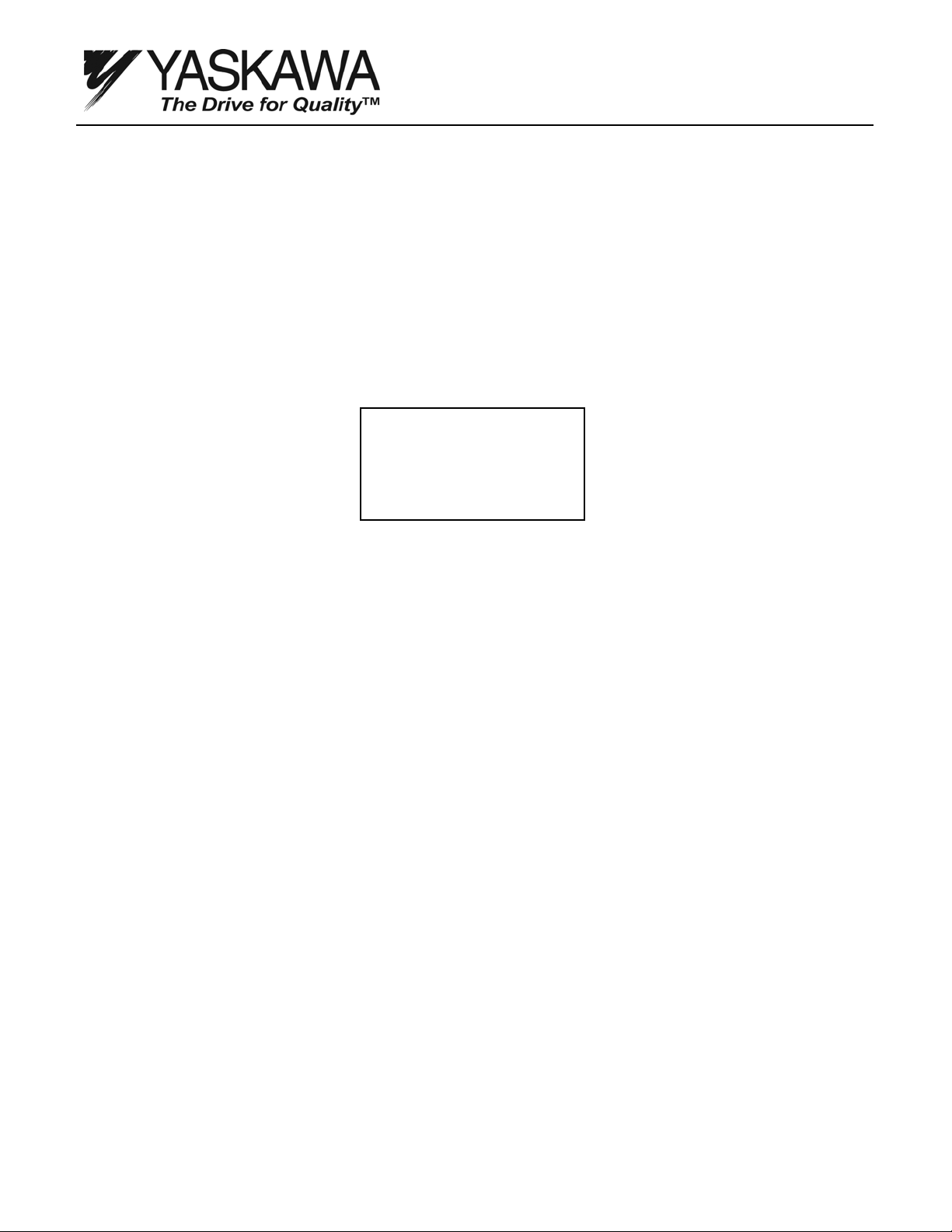
Figure 1: Example of Null Parameter Value
Affected Part/Model Numbers
CIMR-G7*40550B CIMR-G7*40550C
CIMR-G7*40750B CIMR-G7*40750C
CIMR-G7*40900B CIMR-G7*40900C
CIMR-G7*41100B CIMR-G7*41100C
CIMR-G7*41320B CIMR-G7*41320C
CIMR-G7*41850B CIMR-G7*41850C
CIMR-G7*42200B CIMR-G7*42200C
CIMR-G7*43000B CIMR-G7*43000C
*denotes spec. A, C, U, P, or S
-ADV-
+U On Delay
-----------------------n9-47 = 0.00μs
TM.G7.02 Page 1 of 5 Rev: 08-08, 08/22/2008
Page 2
Control Board Replacement Procedure
for Large Capacity G7 Drives
Recommended Procedure for Replacing a Control Board in a CIMR-G7* 4055 to 4300
of Revision B or Later
Note: Follow all precautions in the drive’s technical manual, Document TM.G7.01, for safe wiring and operation of
the G7 Drive during auto-tuning.
Note: An appropriately sized motor with a FLA that closely matches the G7s rated output current needs to be
connected to the G7 while performing the Shipping Adjustment auto-tuning function. Tuning with a motor that is
considerably smaller than the G7 may adversely affect the perfo rmance of the G7.
Note: The motor will not rotate while performing Shipping Adjustment Auto-tuning. Therefore, the motor does not
need to be disconnected from the load. However, take appropriate precautions to secure the load and insulate the
motor terminals as voltage will be applied to the motor.
1. Before replacing the control board, use the COPY function of the digital operator to copy the G7 parameter
settings. When using the COPY function, first confirm the replacement control board software matches the
original control board software. The original control board software version can be viewed using the digital
operator by viewing monitor U1-14. Confirm the last 4 digits of the value monitored in U1-14 match the last 4
digits of the replacement control board part number (-SXXXX). The COPY function cannot be used if the
software version is different on the replacement control board. Manual parameter recording using the
Modified Constants Menu with the original control board will be necessary if the software versions do not
match. If in doubt, manually record the modified parameters as they appear in the original Control Board
Modified Constants Menu. In addition, record the setting of A1-02 (control method selection) for Step 4.
Item
Control Board Part Number ETCXXXXXX-SYYYY ETCXXXXXX-SYYYY
Software number (U1-14)
Inverter capacity (o2-04)
Control method (A1-02)
2. Replace the control board.
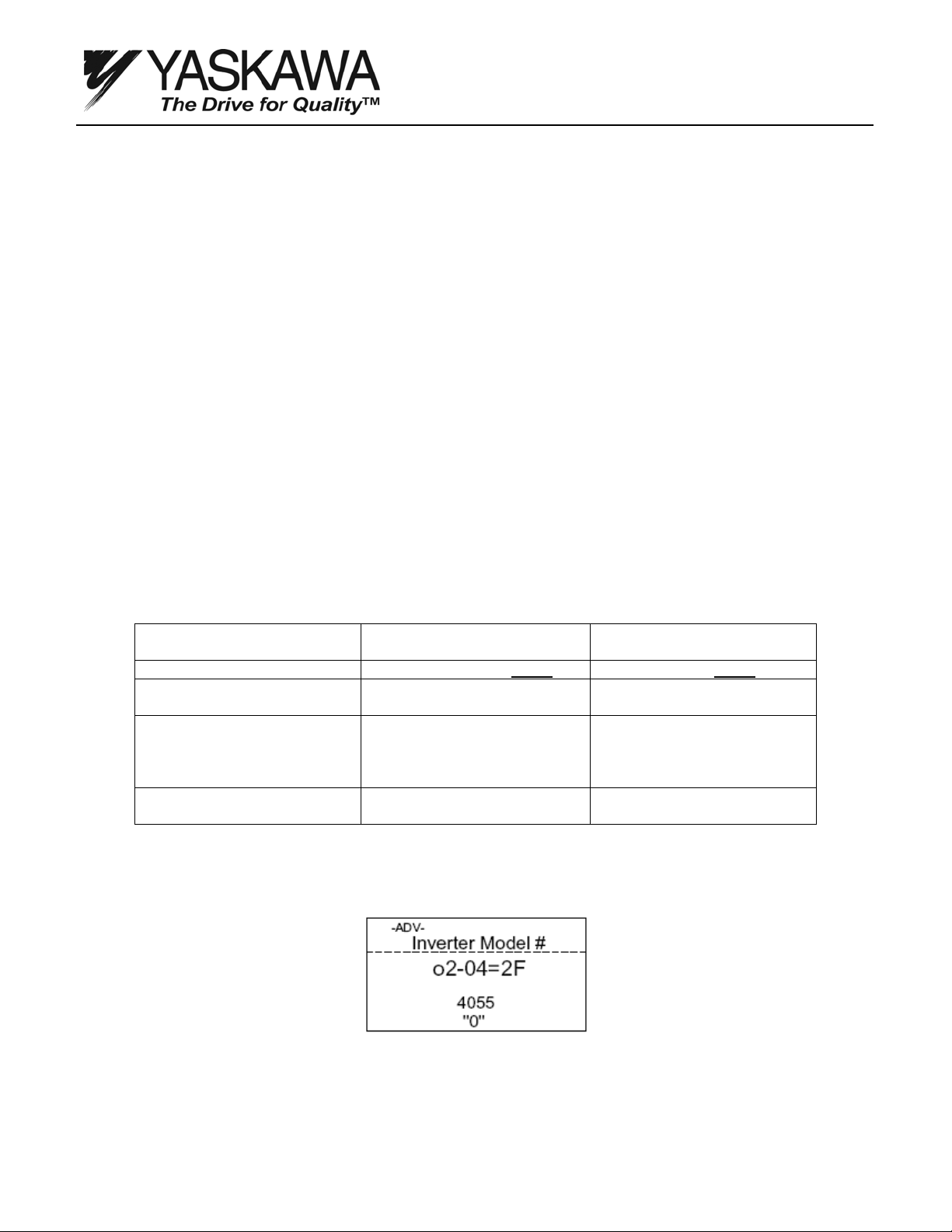
3. Change the kVA setting (o2-04) to match the G7s power section. See Figure 2.
Original Control Board
Value
(confirm same as original
Control PCB)
(set same as original Control
PCB to match the drive’s
power rating. Refer to Step 3
below)
(set same as original Control
PCB. Refer to Step 4 below)
Replacement
Control Board
Figure 2: Drive kVA Setting
TM.G7.02 Page 2 of 5 Rev: 08-08, 08/22/2008
Page 3
Control Board Replacement Procedure
for Large Capacity G7 Drives
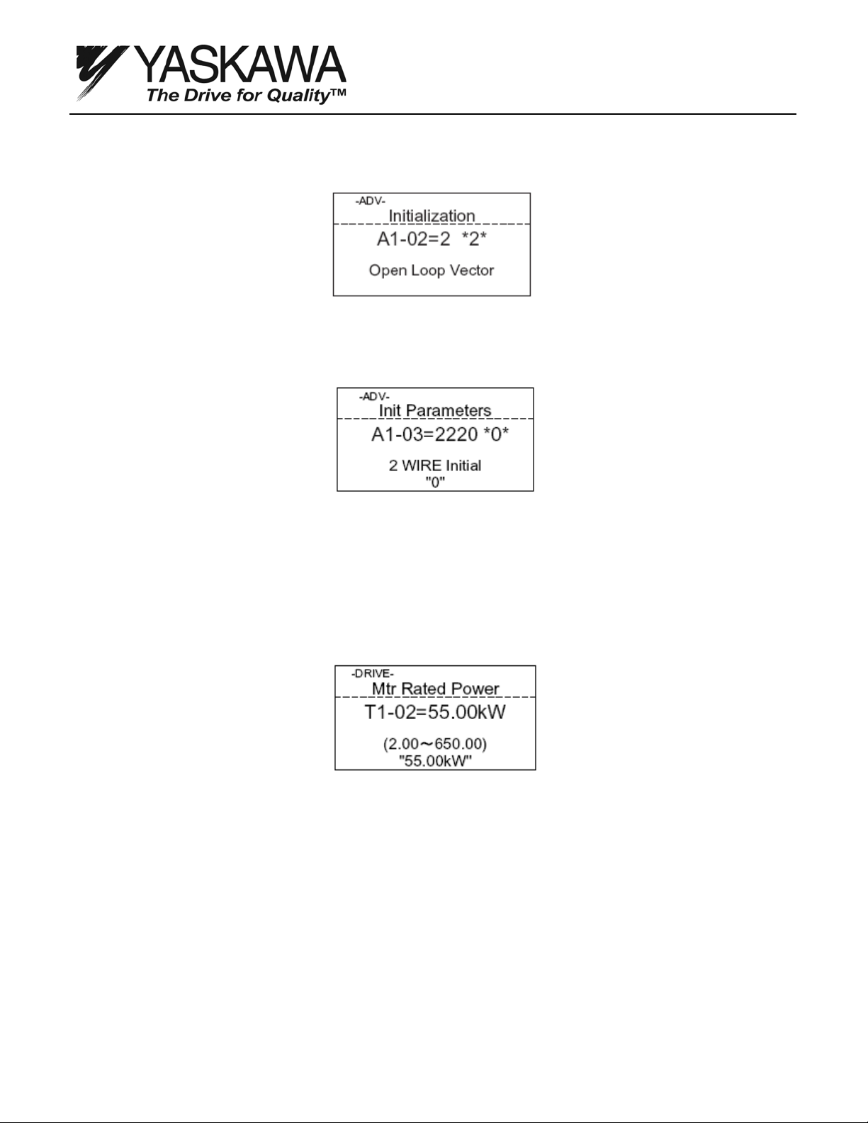
4. Set the control method (A1-02). Refer to the value noted in Step 1. See Figure 3.
Figure 3: Set Control Method
5. Initialize the G7. See Figure 4.
Figure 4: Initialize Drive
6. Upon entering the G7s Operation menu, the motor rated power (T1-02) is automatically displayed. Enter
the motor rated power (in kW) and press DATA/ENTER. See Figure 5. Then, proceed to Step 10.
If motor rated power is not automatically displayed upon entering the G7s Operation Menu this means the
kVA setting may already have been programmed and the Shipping Adjustment Auto-tuning will have to be
accessed by performing Steps 7 thru 9. Proceed to Step 7.
Figure 5: Auto-tuning Set-up
7. Set the factory access level password (A1-04 = 0616).
8. Set the access level to factory (A1-01 = 616).
9. Enable “Shipping Adjustment” auto-tuning by setting parameter o2-16 = 1.
TM.G7.02 Page 3 of 5 Rev: 08-08, 08/22/2008
Page 4
Control Board Replacement Procedure
for Large Capacity G7 Drives
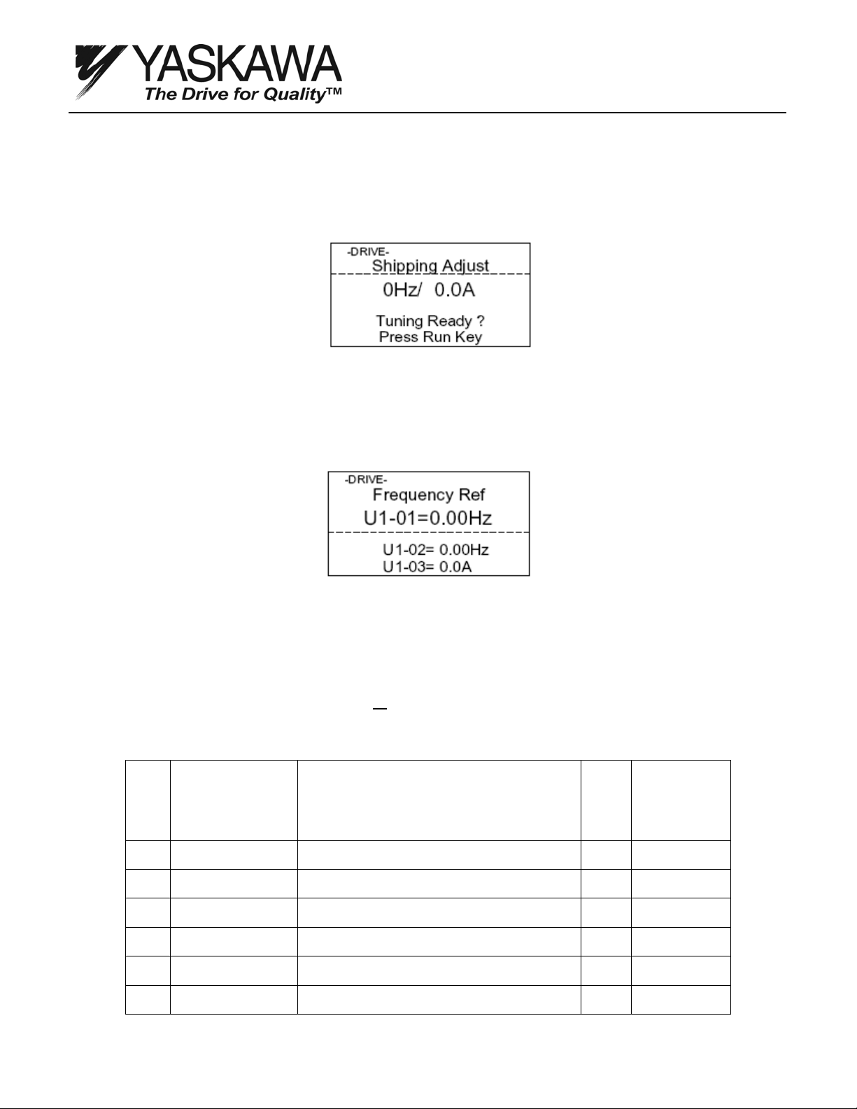
10. The “Shipping Adjust” screen is displayed. See Figure 6. Confirm the output contactor or disconnect
between the motor and drive (if applicable) is closed to ensure the motor is connected to the G7.
Verify it is safe to begin auto-tuning and press RUN.
Figure 6: Auto-tuning Start
11. Drive auto-tuning will run for approximately two minutes. Note: Do not touch the motor terminals.
Although the motor may not rotate, voltage is being applied to the motor. When complete, the G7
display shows the standard Operation menu. See Figure 7.
Figure 7: Auto-tuning Complete
12. After auto-tuning, verify the on-delay compensation values have been set.
13. In the G7s Programming menu, set the factory access password (A1-04 = 0616).
14. Set the factory access level (A1-01 = 616)
15. Check and record (but do not edit) the values of parameters n9-47 thru n9-52. The values should vary
from -10.00μs to 10.00μs and must not all
be 0.00μs. Some settings of zero are acceptable. If all settings
indicate 0.00μsec, the procedure has not been performed properly. Repeating this procedure will be
necessary. Proceed back to Step 3 to repeat the Shipping Adjustment Auto-tuning process.
No.
n9-47
n9-48
n9-49
n9-50
n9-51
n9-52
Parameter Name
LCD Display
On-Delay Comp U+
+U On Delay
On-Delay Comp U-
-U On Delay
On-Delay Comp V+
+V On Delay
On-Delay Comp V-
-V On Delay
On-Delay Comp W+
+W On Delay
On-Delay Comp W-
-W On Delay
Description Range
Sets the degree of bias on the positive side of the Uphase for On-Delay Compensation (n9-12, -31, -32).
Sets the degree of bias on the negative side of the U-
phase for On-Delay Compensation (n9-12, -31, -32).
Sets the degree of bias on the positive side of the Vphase for On-Delay Compensation (n9-12, -31, -32).
Sets the degree of bias on the negative side of the V-
phase for On-Delay Compensation (n9-12, -31, -32).
Sets the degree of bias on the positive side of the W-
phase for On-Delay Compensation (n9-12, -31, -32).
Sets the degree of bias on the negative side of the W-
phase for On-Delay Compensation (n9-12, -31, -32).
-10.00~
10.000
-10.00~
10.000
-10.00~
10.000
-10.00~
10.000
-10.00~
10.000
-10.00~
10.000
Resulting Setting
____ uS
____ uS
____ uS
____ uS
____ uS
____ uS
TM.G7.02 Page 4 of 5 Rev: 08-08, 08/22/2008
Page 5

Control Board Replacement Procedure
for Large Capacity G7 Drives
16. Upon successful auto-tuning, disable access to the factory level (A1-01=2) and clear the factory access
password (A1-04 = 0000).
17. Use the COPY function of the operator to paste the parameter settings from the old control board to the
new one. If the COPY function is unavailable, enter the previously recorded Modified Constants settings
manually (as recorded Step 1 above).
18. This completes the procedure.
Note: Contact your Yaskawa representative if any one of the following is true:
a. A motor cannot be connected.
b. The motor being used is two or more HP ratings smaller than the G7 (e.g. G7 = 150HP, Motor = 75HP).
The motor-drive size mismatch could result in improper tuning results.
c. The new control board software version does not match the old control board’s version.
TM.G7.02 Page 5 of 5 Rev: 08-08, 08/22/2008
 Loading...