

Page 1
r
r
V7 Modbus® TCP/IP Option Kit
1. Applicable products: Standard V7 drives (CIMR-V7AM*) with Ethernet
specific software installed (Not V74X or V7N). Check V7 monitor U-10 or
the PRG # on the V7 nameplate for version 8340 or 8350 software.
Note: To order a V7 with Ethernet software, use the following part number
format: CIMR-V7AM****1-057. There is no charge for this upgrade.
2. When using this kit, it is strongly recommended that no connections be
made to the V7 drive's DC Bus terminals (+1 to -) on models CIMRV7AMxxxx1, where xxxx is 25P5, 27P5, 45P5, or 47P5. A connection for a
DC reactor (+1 to +2) or braking resistor (B1 to B2) is allowed.
3. Unpack the CM091 V7 Modbus TCP/IP Option Kit and verify that all
components are present and undamaged.
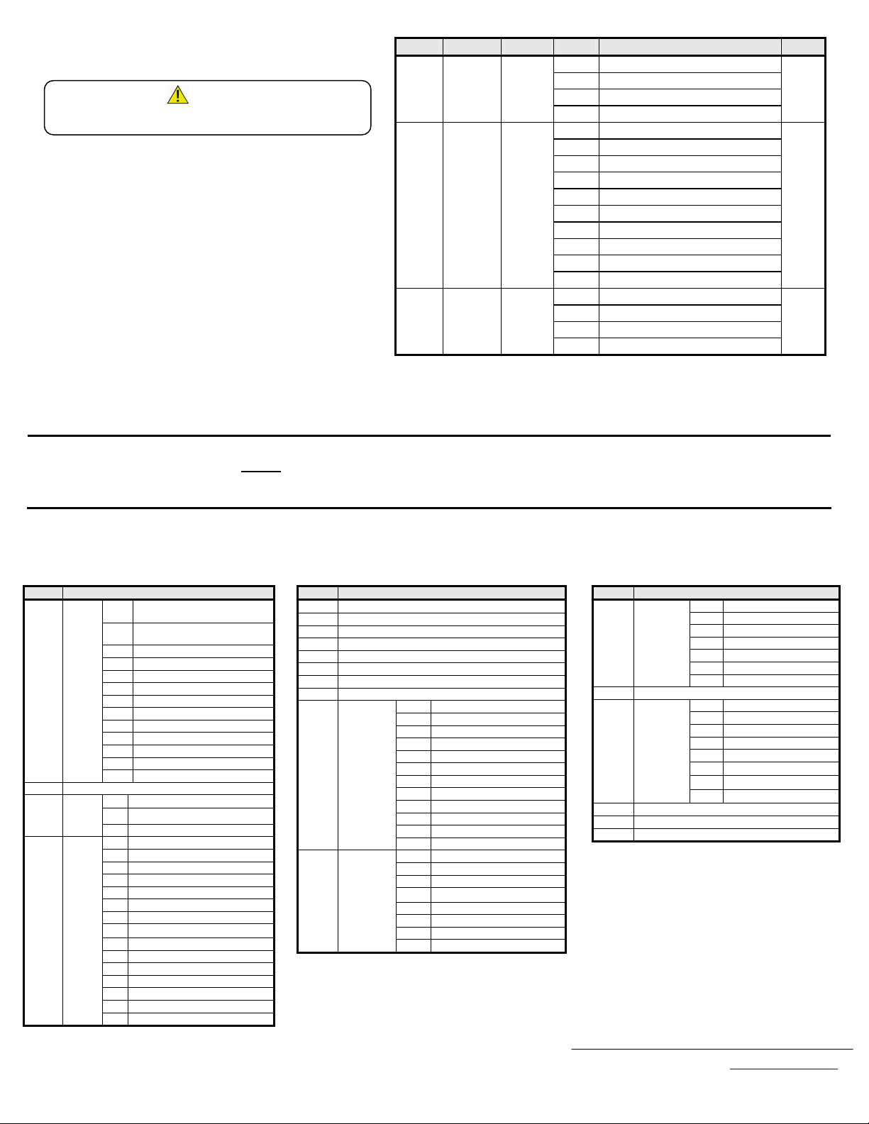
CM091 V7 Modbus TCP/IP Option Kit Parts Qty.
V7 MODBUS TCP/IP Option Ring Kit
1
Mounting Bracket
Option Mounting Bracket 1
Mounting Bracket Screw (M3 x 8) 1
Ferrite (Power and Motor Leads) 2
M3 x 8 Screw
Ferrite (Ethernet Cable) 1
Cable Ties 3
Installation Guide (IG.V7.25) 1
4. Connect power to the V7 drive and verify that the V7 functions correctly.
This includes running the V7 from the operator keypad. Refer to the V7 Technical Manual,
TM.V7.01, for information on connecting and operating the V7 drive.
5. Remove power from the V7 and wait for the charge lamp to be completely extinguished. Wa it
at least five additional minutes for the V7 to be completely discharged. Measure the DC bus voltage
and verify that it is at a safe level.
WARNING!
Dangerous voltages in excess of 400VDC (230V drives) or 800VDC
(460V drives) are present at the DC bus terminals of the drive.
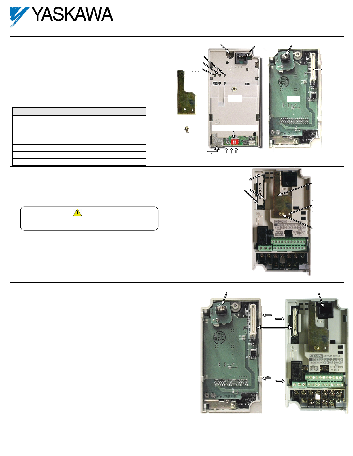
6. Remove the operator keypad and V7 drive cover.
1. Remove the terminal cover by removing the retaining screw and lifting out the cover.
2. Remove the operator keypad.
7. Remove the CN2 cover from the V7 drive housing. Carefully snip the 3 tabs connecting the CN2
cover to the V7 housing and remove the cover.
8. Attach the Mounting Bracket. Align the mounting bracket as shown in the figure to the right.
Secure the mounting bracket to the V7 drive housing using the M3 x 8 screw provided.
9. Wire the V7 I/O terminals prior to mounting the V7 Modbus TCP/IP Option ring kit, as
the option will obscure power and control terminals when mounted.
10. Mount the V7 Modbus TCP/IP Option ring kit on the V7 drive.
1. Do NOT connect a ground wire to the screw on the back of the V7 Modbus TCP/IP
Option kit.
2. Align the CN1 connector on the back of the option with its mating CN2 connector on the
front of the V7.
3. Simultaneously align connector CN3 (male RJ-45) on the back of the option with
connector CN1 (female RJ-45) on the front of the V7.
4. Align the tabs on the option with their corresponding slots on the front of the V7.
5. Press the option and the V7 drive together until the tabs lock into their associated slots.
6. Secure the option to the V7 by tightening the locking screw at the top-center of the
option.
7. Reinstall the operator keypad and all V7 covers.
Locking Screw
Indicator
LEDs
NS/CON
MS/RUN
PWR
RJ-45 Ethernet
Cable Connecto
Front
Load Defaults Switch
10/100, LINK, Rx
Ethernet LEDs
Remove the CN2
protective cover by
carefully clipping the
three tabs.
CN3-Modular Plug
RJ-45 male
CN1-Modular Plug
RJ-45 Female
CN1-Modular Jack
RJ-45 Female
Tab
Slot
CN1 – CN2
Tab
Slot
CM091
CN3-Modular Plug
RJ-45 Male
Back
CN1
Connecto
Option
mounting
bracket
Align hole in the
mounting bracket
with the nib on
the front of
the V7 Drive.
Secure the
mounting bracket
to the V7 with
M3 x 8 screw.
Yaskawa Electric America, Inc – www.yaskawa.com
IG.V7.25, Page 1 of 6
Date: 10/08/09, Rev: 09-10
Page 2
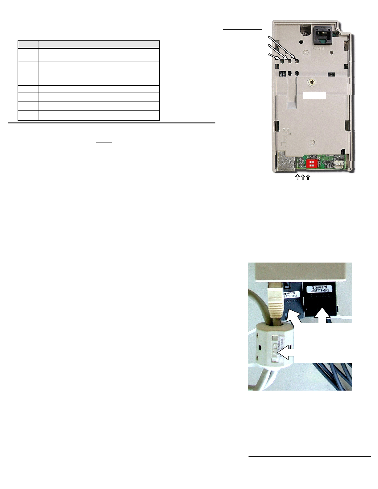
11. LED Descriptions
The V7 Modbus TCP/IP Option LEDs status after the power up sequence is described below.
Please wait for at least five seconds for the loading process to complete before verifying the status
of the LEDs.
LED Description
MS/RUN
GREEN – Card Functioning Normally
RED – Card Failure
GREEN – Connection Made
NS/CON
GREEN BLINK – Control Connection Active
(500ms cycle)
RED – Connection Fault
10/100 GREEN – 100MBPS Connection Speed
LINK
GREEN – Link Established
Rx
GREEN - Message Received
PWR
GREEN - Appropriate Power Supplied to Card
12. Connect to the V7 Modbus TCP/IP Option card.
Note: It is strongly recommended that shielded
1. Connect to the Ethernet network.
1.1. Direct connection: To connect directly to the V7 Modbus TCP/IP Option card, plug one
end of a shielded CAT-5 cross-over cable into the RJ-45 socket on the V7 Modbus
TCP/IP Option card. Connect the other end to the RJ-45 Ethernet socket on the
configuration device, typically a controller, laptop or other PC.
1.2. Connection through hub or switch: To connect through a switch, hub or router, connect
V7 Modbus TCP/IP Option card to the switch, hub or router using a standard shielded
CAT-5 patch cable.
2. Loop the CAT-5 Ethernet cable through the provided ferrite (Intermark RFC-13) and
connect the ferrite as close to the RJ-45 connection as possible. Secure the ferrite to the
Ethernet cable with the provided cable tie. If the ferrite core cannot be mounted in your
installation please contact Yaskawa for application assistance. See the figure in the lower right
corner of this page.
3. Attach the provided ferrites to the V7 drive motor and power leads as close to the V7 drive
terminals as possible (typically within 1 foot). Secure the ferrites to the motor and power leads
with the provided cable ties. See the figure in the lower right corner of this page.
CAT-5 cable be used.
Indicator LEDs
NS/CON
MS/RUN
PWR
Front
10/100, LINK, Rx
Ethernet LEDs
Successful Initialization:
The V7 Modbus TCP/IP Option kit hardware is installed and
operating correctly with the LEDs in the states shown in bold
text in the “LED Descriptions” table. The LINK LED
represents the status of the physical connection to the network
and is not indicative of any card state.
13. Configure the PC Network Connection.
1. Select an existing connection or create a new network connection for communication with
the V7 Modbus TCP/IP Option card.
1.1. Select Start ⇒ Settings ⇒ Network Connections from the task bar in the Windows
OS.
1.2. Select the network connection to be used.
2. Right click on the network connection and select Properties from the menu.
3. Select Internet Protocol (TCP/IP) from the components displayed.
Note: If a TCP/IP selection is not available, it may be installed by selecting Install.
Administrator access to the PC and the operating system installation CD-ROM may also
be required.
3.1. Select Properties.
Note: It is very important to record the existing network setup so that the configuration
PC can be restored to its original configuration.
3.2. Select the Use the following IP address radio button.
3.3. Enter the IP address as 192.168.1.19 and the Subnet mask as 255.255.255.0. Check the
system network schematic or with your network administrator to ensure that the IP
address does not already exist on the network.
3.4. Once the IP address and Subnet mask are entered, select OK.
Note: It may be necessary to reboot the PC in order for the changes to take affect.
Ferrites around power
and motor leads.
Ferrite around looped
CAT-5 Ethernet cable.
Application of Ferrites:
The V7 Modbus TCP/IP Option kit includes 3 ferrites which
must be mounted to the Ethernet cable, incoming power leads,
and motor leads. See Section 12, steps 2 and 3.
Yaskawa Electric America, Inc – www.yaskawa.com
IG.V7.25, Page 2 of 6
Date: 10/08/09, Rev: 09-10
Page 3
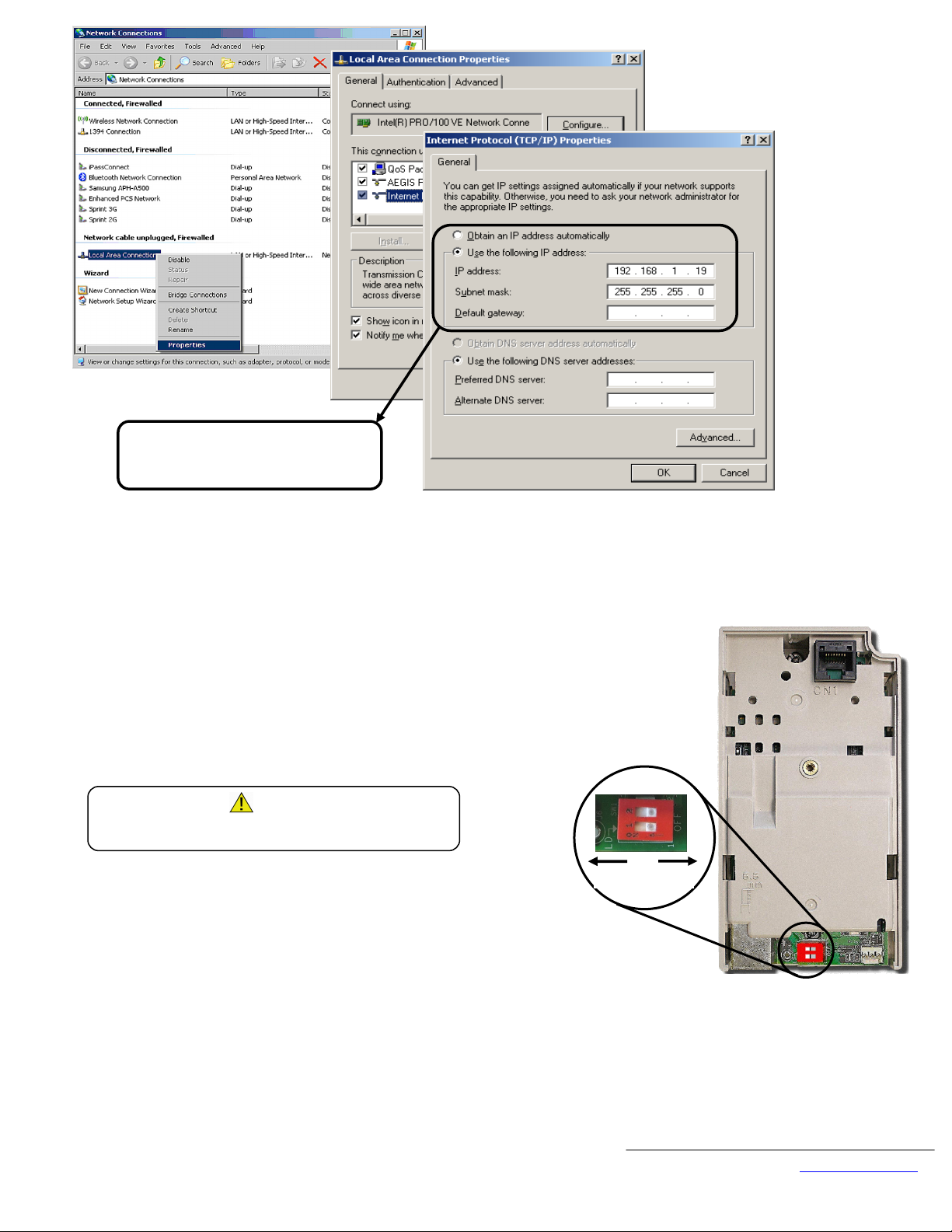
IP address: 192.168.1.19
Subnet mask:
255.255.255.0
14. Resetting the V7 Modbus TCP/IP Option card to the default address (if needed).
1. The factory default settings are as follows:
Configure Network Parameters: USER
IP Address: 192.168.1.20
Subnet: 255.255.255.0
Gateway: 192.168.1.1
EF0 Timeout: 5.0 seconds
Gateway Usage: Disabled
Symptom: The V7 Modbus TCP/IP Option card main web page does not display on the PC web
browser screen.
Corrective Action: Check that the PC is setup and properly connected.
If the web page is still not visible after confirming PC setup, then reset the IP address of the V7
Modbus TCP/IP Option card to its factory default as follows:
1.1. Remove power from the V7 drive and wait for the charge lamp to be completely
extinguished. Wait at least five additional minutes for the V7 to be completely discharged.
Measure the DC bus voltage and verify that it is at a safe level.
Dangerous voltages in excess of 400VDC (230V drives) or 800VDC
(460V drives) are present at the DC bus terminals of the drive.
1.2. Slide the bottom Load Defaults (LD) switch (SW1) to the ON position.
1.3. Reapply power to the V7 and wait approximately 10 seconds for the power-up cycle to
complete.
Note: Additional wait time (approximately 2 minutes) may be required if utilizing the DHCP
feature of this card, and the DHCP server is not available, or it did not respond to the request
for an IP address. The V7 Modbus TCP/IP Option card will indicate that the load defaults is
complete when the MS/RUN LED is displaying a steady green status indication after the wait
time.
1.4. Remove power from the V7 and wait for the charge lamp to be completely extinguished.
Wait at least five additional minutes for the V7 to be completely discharged. Measure the DC
bus voltage and verify that it is at a safe level.
1.5. Slide the bottom Load Defaults (LD) switch (SW1) to the OFF position.
1.6. Reapply power to the V7 and wait approximately 10 seconds for the power-up cycle to
complete.
1.7. Direct the PC web browser to IP address 192.168.1.20 and the V7 Modbus TCP/IP Option
card main web page should now be displayed.
WARNING!
ON OFF
Yaskawa Electric America, Inc – www.yaskawa.com
IG.V7.25, Page 3 of 6
Date: 10/08/09, Rev: 09-10
Page 4
5.0
15.
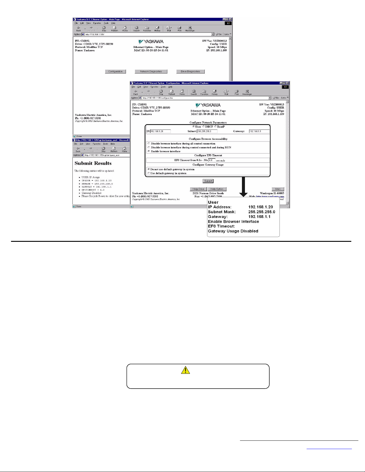
Configure the V7 Modbus TCP/IP Option card.
1. Select the Configure button from the V7 Modbus TCP/IP Option card main page.
2. Select the way in which the V7 Modbus TCP/IP Option card should obtain its network address.
2.1. User. The V7 Modbus TCP/IP Option card will use the network address as entered in the IP, Subnet, and Gateway fields. Check with the system schematic or
network administrator to verify that the IP address and subnet mask entered are valid.
2.2. DHCP. The V7 Modbus TCP/IP Option card will get its network address information upon power-up from an appropriate DHCP server.
2.3. BootP. The V7 Modbus TCP/IP Option card will get its network address information upon power-up from an appropriate BootP server.
3. Select the EF0 Timeout Value between 0.1 seconds to 30.0 seconds.
4. Select the Gateway Usage. Connectivity to the option card may be limited or nonfunctional, if the gateway usage setting and gateway address does not match the
network infrastructure in which it is installed.
4.1. Do not use default gateway in system. Use this option to disable the gateway when there is no external gateway in your network.
4.2. Use default gateway in system. Use this option to enable the gateway, when there is an external gateway present on the network. Verify and/or update the
gateway address as necessary, so that it correctly matches the address of the installed network gateway equipment.
5. Select the Submit button.
6. A confirmation of the entered configuration selections will be displayed in the web browser on the Submit Page.
7. Remove power from the V7 drive and wait for the charge lamp to be completely extinguished. Wait at least five additional minutes for the V7 to be completely
discharged. Measure the DC bus voltage and verify that it is at a safe level.
WARNING!
Dangerous voltages in excess of 400VDC (230V drives) or 800VDC
(460V drives) are present at the DC bus terminals of the drive.
8. If necessary, reconfigure the network connection of the configuration device to match the entered V7 Modbus TCP/IP Option card configuration.
9. Reapply power to the V7 and connect to the desired network. Refresh the web browser to verify that the main web page is displayed.
Yaskawa Electric America, Inc – www.yaskawa.com
IG.V7.25, Page 4 of 6
Date: 10/08/09, Rev: 09-10
Page 5
16. Remove power from the V7 drive and wait for the charge lamp to be
(
completely extinguished. Wait at least five additional minutes for the V7
to be completely discharged. Measure the DC bus voltage and verify
that it is at a safe level.
Dangerous voltages in excess of 400VDC (230V drives) or 800VDC
460V drives) are present at the DC bus terminals of the drive.
WARNING!
17. Reinstall the operator keypad and terminal cover.
18. Reapply power to the V7 drive.
19. Set parameters n003 and n004 to their appropriate values.
Important Notes:
1. Note: A maximum of 10 simultaneous connections are allowed.
2. The Run Command and Frequency Reference may only be accessed
through UNIT ID 1. While the V7 drive is in remote Run mode, the
Run command must be continually refreshed within the configured
EF0 timeout value. If the Run command is not refreshed within the set
timeout period, an EF0 fault will occur. Refer to the appropriate V7
manual for information on EF0 and setting the appropriate V7
response. If a UNIT ID 1 connection is active, the NS/CON LED will
blink at approximately a 500ms cycle.
3. The TCP/IP connection must be refreshed within 60 seconds. If it is
not refreshed within 60 seconds, the connection will be closed.
4. This implementation of Modbus TCP/IP supports the following Modbus functions: 3 (read multiple registers), 6 (write single register), 16 (write multiple registers) and
23 (read/write multiple registers).
5. Refer to the appropriate programming or parameter access manual for a complete list of V7 parameters and registers available. A list of applicable manuals is available
at the end of this document.
Address Parameter Function Data Description Default
0 Operator Keypad
103h n003
Operation
Method
Selection
1 Terminal Strip
2 Built-in Modbus RTU
3
Option Kit (V7 Modbus TCP/IP Option)
0 Operator Keypad Potentiometer
1 Operator Keypad
2 Voltage Reference (0-10VDC)
3 Current Reference (4-20mA)
104h n004
Reference
Selection
4 Current Reference (0-20mA)
5 Pulse Train Reference
6 Built-in Modbus RTU
7 Multi-Function Analog Input (0-10VDC)
8 Multi-Function Analog Input (4-20mA)
9
Option Kit (V7 Modbus TCP/IP Option)
0 0.01 Hz
198h n152
Display
Scaling
1 0.1 %
2-39 RPM (Enter motor poles)
40-3999 User Setting
1
2
0
20. Notes:
1. It is strongly recommended that shielded
2. DriveWizard version 6.1 or later with a custom database is required for DriveWizard to operate with this option. Install DriveWizard with the
“Custom” install option checked and the appropriate databases selected.
CAT-5 cable be used. Verify that the shield is continuous to the drive and that it is grounded only at the drive end.
21. Registers Available via High-Speed Command Registers
Command Register access is designed to be used as part of the standard PLC I/O or scan table, where fast response is required. Other register values should be accessed via
individual messages, i.e. via an MSTR block. Addresses 0001h, 0002h and 0009h may be written while all other registers in the table below are read only. Addresses 0001h and
0002h may only be accessed through Unit ID 1 (see above). Please note that Modbus RTU has different command registers.
Address Description
Digital
0001h
Input
Command
0002h Frequency Reference Command (Scaled by n152)
Digital
0009h
Output
Command
Status
2000h
Word
Multi-Function Digital Input S1
0h
(Forward Run)
Multi-Function Digital Input S2
1h
(Reverse Run)
2h Multi-Function Digital Input S3
3h Multi-Function Digital Input S4
4h Multi-Function Digital Input S5
5h Multi-Function Digital Input S6
6h Multi-Function Digital Input S7
7h Reserved
8h Ex ternal Fault (EF0)
9h Fault Reset
Ah-Dh Reserved
Eh Fault Log Trace Clear
Fh External Base Block
0h Terminals MA, MB, MC
1h Terminals P1, PC
2h Terminals P2, PC
0h During Run
1h Zero Speed
2h Reverse Direction
3h During Fault Reset
4h Speed Agree
5h Drive Ready
6h Minor Fault (Alarm)
7h Major Fault
8h OPE Fault
9h Momentary Powerloss Ride Thru
Ah Local Mode
Bh Digital Output Terminals MA, MB, MC
Ch Digital Output Terminals P1, PC
Dh Digital Output Terminals P2, PC
Eh-Fh Reserved
Address Description
2001h Output Frequency (U-02) (Scaled b y n152)
2002h Torque Monitor (U-08) (1%) (Open Loop Vector only)
2003h Reserved
2004h Frequency Reference Monitor (U-02) (Scaled by n152)
2005h Output Frequency (U-02) (Scaled b y n152)
2006h Output Current (U-03) (0.1A)
2007h Pulse Input (Terminal RP) Value
2008h DC Bus Voltage (U-05) (1VDC)
2009h Error Signal 1
200Ah Error Signal 2
0h Reserved
1h UV1 Main Circuit Undervoltage
2h UV2 Control Power Undervoltage
3h Reserved
6h OC Overcurrent
7h OV Overvoltage
8h OH Overheat
9h Reserved
Ah OL1 Motor Overload
Bh OL2 Drive Overload
Ch OL3 Overtorque Detection
Dh-Fh Reserved
0h EF3 External Fault S3
1h EF4 External Fault S4
2h EF5 External Fault S5
3h EF6 External Fault S6
4h EF7 External Fault S7
5h ~ Ch Reserved
Dh oPA Operator Disconnected
Eh ~ Fh Reserved
Address Description
200Bh Error Signal 3
200Ch Reserved
Digital Input
200Dh
200Eh Analog Input (Terminal FR) Value (0.1VDC)
200Fh Reserved
2010h Drive Software Number (U-10)
Terminal
Status
0h CE Communications Fault
1h BUS Option Error
2h ~ 5h Reserved
6h EF0 Option External Error
8h UL3 Undertorque Detection
9h ~ Eh Reserved
Fh Fxx Hardware Fault
0h Terminal S1
1h Terminal S2
2h Terminal S3
3h Terminal S4
4h Terminal S5
5h Terminal S6
6h Terminal S7
7h ~ Fh Reserved
Yaskawa Electric America, Inc – www.yaskawa.com
IG.V7.25, Page 5 of 6
Date: 10/08/09, Rev: 09-10
Page 6

Modbus® TCP/IP Option
CM091
Copies of this Installation Guide along with all technical manuals in “.pdf” format and support files may be obtained from either the CD supplied with the V7 Drive or
from www.yaskawa.com
obtained from www.modbus.org.
. Printed copies of any Yaskawa manual may be obtained by contacting the nearest Yaskawa office. Information on Modbus TCP/IP may be
Reference documents:
V7 Drive Technical Manual – TM.V7.01
Technical Manual for V7 Modbus RTU – TM.V7.11
YASKAWA ELECTRIC AMERICA, INC.
Chicago-Corporate Headquarters
2121 Norman Drive South, Waukegan, IL 60085, U.S.A.
Phone: (800) YASKAWA (800-927-5292) Fax: (847) 887-7310
Internet: http://www.yaskawa.com
YASKAWA ELECTRIC CORPORATION
New Pier Takeshiba South Tower, 1-16-1, Kaigan, Minatoku, Tokyo, 105-0022, Japan
Phone: 81-3-5402-4511 Fax: 81-3-5402-4580
Internet: http://www.yaskawa.co.jp
YASKAWA ELECTRIC EUROPE GmbH
Am Kronberger Hang 2, 65824 Schwalbach, Germany
Phone: 49-6196-569-300 Fax: 49-6196-888-301
Data subject to change without notice.
Yaskawa Electric America, Inc – www.yaskawa.com
IG.V7.25, Page 6 of 6
Date: 10/08/09, Rev: 09-10
 Loading...