

Page 1
PROFIBUS-DP® Option Card
Unpack the V7 PROFIBUS-DP Option and verify that all components are present and undamaged.
Part Qty.
V7 PROFIBUS-DP Option Card Ring Kit 1
Mounting Bracket 1
M3×8 Screw 1
6” Ground Wire (150mm) 1
8.5” Ground Wire (220mm) 1
12.5” Ground Wire (320mm) 1
Installation Guide (IG.V7.12) 1
Connect power to the drive and verify that the drive functions correctly. This includes running the
drive from the operator keypad. Refer to the V7 Technical Manual, TM.V7.01, for information on
connecting and operating the drive.
Remove power from the drive and wait for the charge lamp to be completely extinguished. Wait at
least five additional minutes for the drive to be completely discharged. Measure the DC BUS
voltage and verify that it is at a safe level.
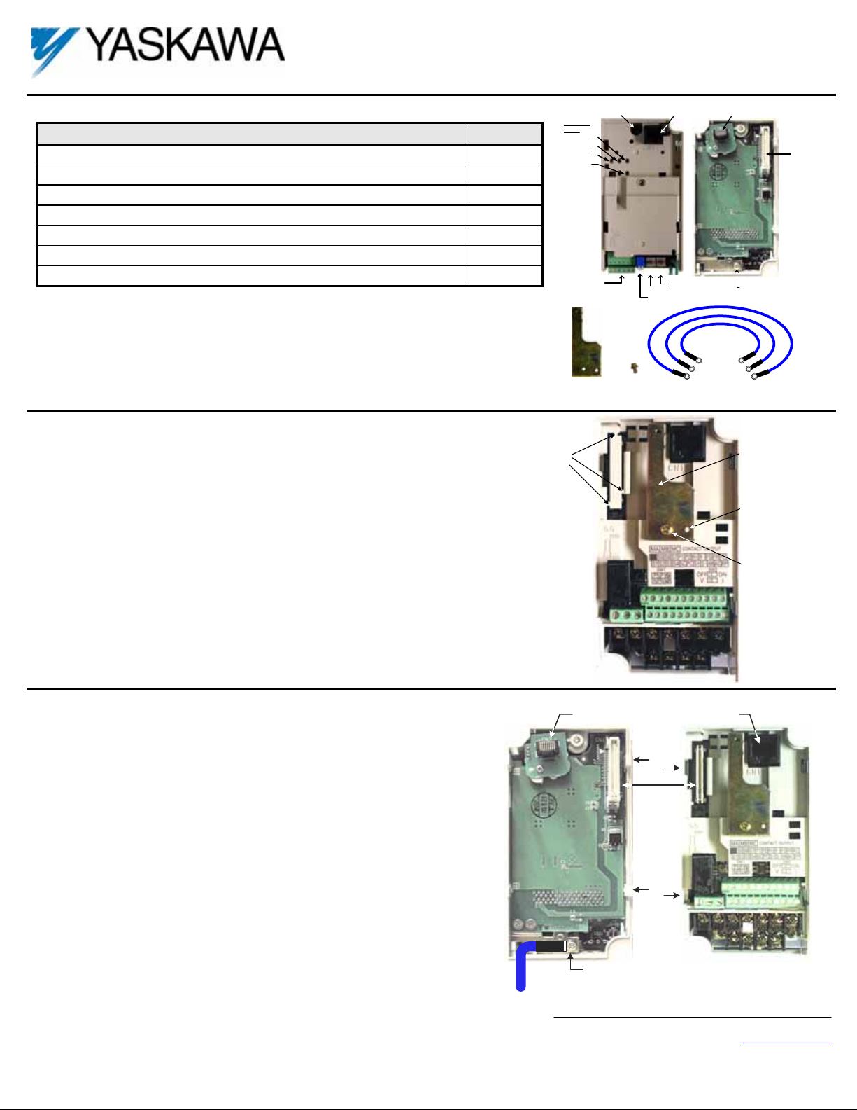
Locking Screw
Indicator
LEDs
ERR
COMM
PWR
WD
Profibus Cable
Connector
Mounting Bracket
Front
M3x8 Screw
CN1 - Modular Plug
RJ45 Female
S2 S1
Node Address
Switches
Termination Switch
E
E
E
CM067
CN3 - Modular Pl ug
RJ45 Male
Back
Ground Wire Connection
Ground Wires
6" (150mm)
8.5" (220mm)
12.5" (320mm)
CN1
Connector
E
E
E
Prepare the drive for the V7 PROFIBUS-DP Option.
Remove the V7 operator keypad and terminal cover.
Remove the plastic protective cover from over the CN2 connector and install
the option mounting bracket provided on to the drive.
Connect the ground wire provided to the ground connector on the back of the V7
PROFIBUS-DP Option.
Mount the V7 PROFIBUS-DP Option onto the drive
Align the CN1 connector on the back of the option with its mating CN2
connector on the front of the drive.
Simultaneously align the CN3 connector, the male RJ45 connector, on the back
of the option with the CN1 connector, the female RJ45 connector, on the front
of the drive.
Align the tabs on the option with their corresponding slots on the front of the
drive.
Press the option and the drive together until the tabs lock into their associated
slots.
Secure the option to the V7 drive by tightening the locking screw at the top-
center of the option.
Connect the ground wire from the V7 PROFIBUS-DP Option to ground terminal
on the V7 drive.
Reinstall the operator keypad and all drive covers.
Remove the CN2
protective cover by
carefully clipping
the three tabs
CN3 - Male RJ45
Connector
E
Ground Wire
CN2 Cover
Tab
CN1 - CN2
Tab
Ground Terminal
CN1 - Female
RJ45 Connector
Slot
Slot
Option
mounting
bracket
Align hole in
mounting bracket
with nib on front of
the V7 drive
Secure mounti ng
bracket to V7 drive
with M3x8 screw
Yaskawa Electric America, Inc – www.drives.com
IG.V7.12, Page 1 of 4
Date: 07/01/04, Rev: 04-07
Page 2
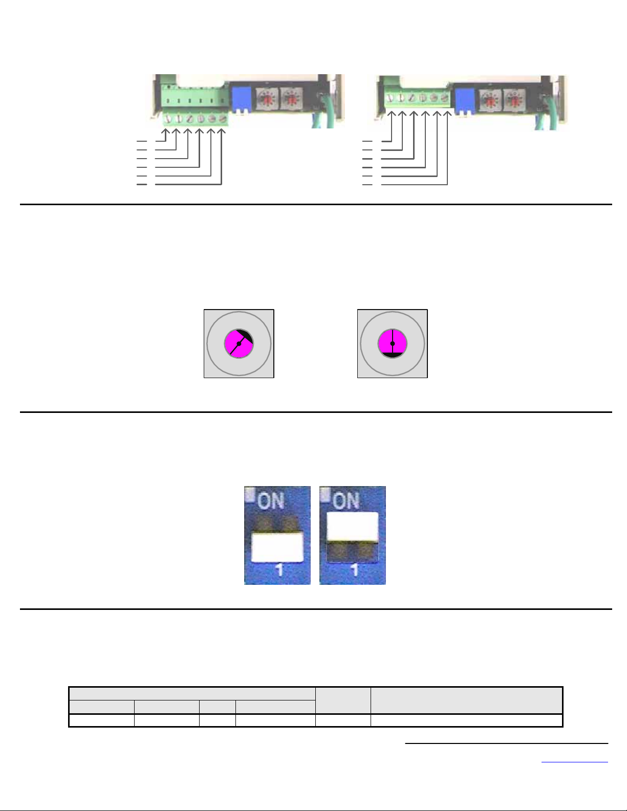
Connect the V7 to the PROFIBUS-DP communication network.
Determine the type of connector on the V7 PROFIBUS-DP Option. Connector Style A is a modified Phoenix pluggable connector. The modification can be
seen on the back of the connector as a small circuit board. Connector Style B is a standard, unmodified Phoenix pluggable connector.
Connector Style A Connector Style B
A In (Green)
B In (Red)
A Out (Green)
B Out (Red)
Shield
Reserved
Set the node address
Set the node address for the drive setting the 10‘s digit with S2 and the 1’s digit with S1. All devices on the network must have unique node addresses.
Check the network layout to verify that the node address selected is unique and falls between 3 – 99. Node addresses 0 and 1 are typically reserved for
master controllers. Node address 2 is typically reserved for diagnostic equipment.
Set network termination
If this drive is either the first or the last device on the network, including any PLC and/or PROFIBUS-DP Master, and active termination is not used, set the
termination resistor switch to ON. If this device is not the first or last device on the network or active termination is used, set the termination resistor switch
to OFF. Active termination is the recommended termination method and is required for networks operating above 1.5Mbps. Active termination will eliminate
the possibility of network failure due to the removal of a device with termination set to ON. The Siemens PROFIBUS Terminator part number is 6ES7 9720DA00-0AA0.
1
2
3
4
5
6
Address = (Switch 2 x 10) + (Switch 1 x 1)
Example: Set node address to 15
Set address switch 2 to "1 Set address switch 1 to "5"
0
1
9
6
S2
2
3
4
5
8
7
Reserved
Reserved
A In/Out (Green)
B In/Out (Red)
Shield
Reserved
OFF
ON
1
2
3
4
5
6
0
1
9
6
S1
2
3
4
5
8
7
Secure the V7 PROFIBUS-DP Option to the drive by tightening the recessed screw located at the top center of the option.
Configure the PROFIBUS network for the drive. Refer to the documentation included with the PROFIBUS configuration utility supplied with the PROFIBUS-
DP Master controller.
Apply power to the drive and verify that the diagnostic LED’s on the front of the V7 PROFIBUS-DP Option are in their correct state.
LED Display
PWR COM ERR WD
Solid Green Solid Green OFF Flashing Green Normal Normal communication possible.
Content Cause
Yaskawa Electric America, Inc – www.drives.com
IG.V7.12, Page 2 of 4
Date: 07/01/04, Rev: 04-07
Page 3

Remove power from the drive and wait for the charge lamp to be completely extinguished. Wait at least five additional minutes for the drive to be
completely discharged. Measure the DC BUS voltage and verify that it is at a safe level.
Reinstall the operator keypad and terminal cover.
Set parameters n003, n004 and n035 to their appropriate values
Addr Param Function Data +/- Limits - Description Default
0 Operator keypad
103h n003 Operation Method Selection
104h n004 Reference Selection
123h n035 Frequency Reference Unit Selection
1 Terminal
2 Serial Communication
3 Option Card (PROFIBUS-DP Option)
0 Operator keypad Pot
1 Operator keypad
2 Voltage Reference (0-10v)
3 Current Reference (4-20 Ma)
4 Current Reference (0-20 Ma)
5 Pulse Train Reference
6 Serial Communication
7 Multi-Function Analog Input (0-10vdc)
8 Multi-Function Analog Input(4-20ma)
9 Option Card (PROFIBUS-DP Option)
0.01 Hz (< 100hz), 0.1hz (100 Hz
0
>=100hz)
1 0.1%
2-39 Rpm
40-3999 User Setting
1
2
0
LED Status Indicators and Diagnostics
LED Display
PWR COM ERR WD
OFF OFF OFF OFF
Solid
Green
Solid
Green
Solid
Green
Solid
Green
Solid
Green
Solid
Green
OFF
OFF
OFF
Solid
Green
Solid
Green
Solid
Green
Solid
Red
Solid
Red
Flashing
Red
Flashing
Red
OFF
OFF
Solid
Red
Flashing
Red
Solid
Green
Solid
Green
Solid
Green
Flashing
Green
Content Cause Counter measures
• Check the main circuit wiring on the
drive.
• Cycle drive power.
• Turn of the drive power.
• Check the option unit connection to
the drive.
• Cycle drive power.
• Cycle drive power.
• Replace option unit if fault persists.
• Cycle drive power.
• Replace drive if fault persists.
• Check whether the address set in
the PROFIBUS-DP Master differs
from the address of the option unit.
• Check that the master is functioning
properly.
• Check that the termination resistor
is correctly connected to the
communication line.
• Check whether the communication
line is correctly connected
(disconnected or poor connection).
• Check that the communication line
is separated from the main power
line.
• Check whether the address is
duplicated with any other devices
within the PROFIBUS-DP network.
• Wait for WD LED to start flashing.
Power
OFF
CPU
Error
Drive
Error
Com
Error
Com
Error
CPU
Init
Normal
Power is not being fed
from the drive.
Power is not being
provided to the option unit
due to poor option unit
connection.
Option unit CPU error.
Error in Drive unit.
A fault has occurred
rendering communication
impossible.
A fault has occurred
rendering communication
impossible.
Option unit under
initialization
Normal communication
possible.
Yaskawa Electric America, Inc – www.drives.com
IG.V7.12, Page 3 of 4
Date: 07/01/04, Rev: 04-07
Page 4

PROFIBUS-DP® Option Card
CM067
Copies of this Installation Guide along with all technical manuals in pdf format and support files may be obtained from either the CD supplied with the drive or from
www.drives.com . Printed copies of any Yaskawa manuals may be obtained by contacting the nearest Yaskawa office. Information on PROFIBUS and
PROFIBUS-DP may be obtained from either the PROFIBUS Organization or at
www.profibus.com .
Reference documents:
V7 Technical Manual –
V7 MODBUS
®
Technical Manual – TM.V7.11
V7 PROFIBUS-DP
TM.V7.01
®
Option Technical Manual – TM.V7.12
V7 PROFIBUS-DP® Option Installation Guide – IG.V7.12
MODBUS
PROFIBUS
®
is a registered trademark of Schneider Automation, Inc.
®
and PROFIBUS-DP® are registered trademarks of PROFIBUS Nutzerorganisation e.V.
YASKAWA ELECTRIC AMERICA, INC.
Drives Division
16555 W. Ryerson Rd., New Berlin, WI 53151, U.S.A.
Phone: (800) YASKAWA (800-927-5292) Fax: (262) 782-3418
Internet: http://www.drives.com
YASKAWA ELECTRIC AMERICA, INC.
Chicago-Corporate Headquarters
2121 Norman Drive South, Waukegan, IL 60085, U.S.A.
Phone: (800) YASKAWA (800-927-5292) Fax: (847) 887-7310
Internet: http://www.yaskawa.com
MOTOMAN INC.
805 Liberty Lane, West Carrollton, OH 45449, U.S.A.
Phone: (937) 847-6200 Fax: (937) 847-6277
Internet: http://www.motoman.com
YASKAWA ELECTRIC CORPORATION
New Pier Takeshiba South Tower, 1-16-1, Kaigan, Minatoku, Tokyo, 105-0022, Japan
Phone: 81-3-5402-4511 Fax: 81-3-5402-4580
Internet: http://www.yaskawa.co.jp
YASKAWA ELETRICO DO BRASIL COMERCIO LTDA.
Avenida Fagundes Filho, 620 Bairro Saude Sao Paolo-SP, Brasil CEP: 04304-000
Phone: 55-11-5071-2552 Fax: 55-11-5581-8795
Internet: http://www.yaskawa.com.br
YASKAWA ELECTRIC EUROPE GmbH
Am Kronberger Hang 2, 65824 Schwalbach, Germany
Phone: 49-6196-569-300 Fax: 49-6196-888-301
MOTOMAN ROBOTICS AB
Box 504 S38525, Torsas, Sweden
Phone: 46-486-48800 Fax: 46-486-41410
MOTOMAN ROBOTEC GmbH
Kammerfeldstrabe 1, 85391 Allershausen, Germany
Phone: 49-8166-900 Fax: 49-8166-9039
YASKAWA ELECTRIC UK LTD.
1 Hunt Hill Orchardton Woods Cumbernauld, G68 9LF, Scotland, United Kingdom
Phone: 44-12-3673-5000 Fax: 44-12-3645-8182
YASKAWA ELECTRIC KOREA CORPORATION
Paik Nam Bldg. 901 188-3, 1-Ga Euljiro, Joong-Gu, Seoul, Korea
Phone: 82-2-776-7844 Fax: 82-2-753-2639
YASKAWA ELECTRIC (SINGAPORE) PTE. LTD.
Head Office: 151 Lorong Chuan, #04-01, New Tech Park Singapore 556741, Singapore
Phone: 65-282-3003 Fax: 65-289-3003
TAIPEI OFFICE (AND YATEC ENGINEERING CORPORATION)
10F 146 Sung Chiang Road, Taipei, Taiwan
Phone: 886-2-2563-0010 Fax: 886-2-2567-4677
YASKAWA JASON (HK) COMPANY LIMITED
Rm. 2909-10, Hong Kong Plaza, 186-191 Connaught Road West, Hong Kong
Phone: 852-2803-2385 Fax: 852-2547-5773
BEIJING OFFICE
Room No. 301 Office Building of Beijing International Club,
21 Jianguomanwai Avenue, Beijing 100020, China
Phone: 86-10-6532-1850 Fax: 86-10-6532-1851
SHANGHAI OFFICE
27 Hui He Road Shanghai 200437 China
Phone: 86-21-6553-6600 Fax: 86-21-6531-4242
SHANGHAI YASKAWA-TONJI M & E CO., LTD.
27 Hui He Road Shanghai 200437 China
Phone: 86-21-6533-2828 Fax: 86-21-6553-6677
BEIJING YASKAWA BEIKE AUTOMATION ENGINEERING CO., LTD.
30 Xue Yuan Road, Haidian, Beijing 100083 China
Phone: 86-10-6232-9943 Fax: 86-10-6234-5002
SHOUGANG MOTOMAN ROBOT CO., LTD.
7, Yongchang-North Street, Beijing Economic & Technological Development Area,
Beijing 100076 China
Phone: 86-10-6788-0551 Fax: 86-10-6788-2878
YEA, TAICHUNG OFFICE IN TAIWAIN
B1, 6F, No.51, Section 2, Kung-Yi Road, Taichung City, Taiwan, R.O.C.
Phone: 886-4-2320-2227 Fax:886-4-2320-2239
Data subject to change without notice
Yaskawa Electric America, Inc – www.drives.com
IG.V7.12, Page 4 of 4
Date: 07/01/04, Rev: 04-07
 Loading...