

Page 1
Profibus-DP® Option Card
CM061 (SI-P1)
This document applies to the Yaskawa G5HHP drive. Please disregard the installation guide packed in the option kit.
Unpack the CM061 Profibus-DP Option kit and verify that all com ponents are present and undamaged.
CM061 Profibus-DP Option Kit Parts List Qty.
Profibus-DP Option Card (SI-P1) 1
Installation Guide (IG.AFD.12) (Disregard for G5HHP) 1
Connect power to the drive and verify that the drive functions correctly. This includes running the drive from the operator keypad. Refer to the appropriate drive technical
manual for information on connecting and operating the drive.
Remove power from the drive and wait for the charge lamp to be completely extinguished. Wa it at least five additional minutes for the drive to be completely discharged.
Measure the DC bus voltage and verify that it is at a safe level.
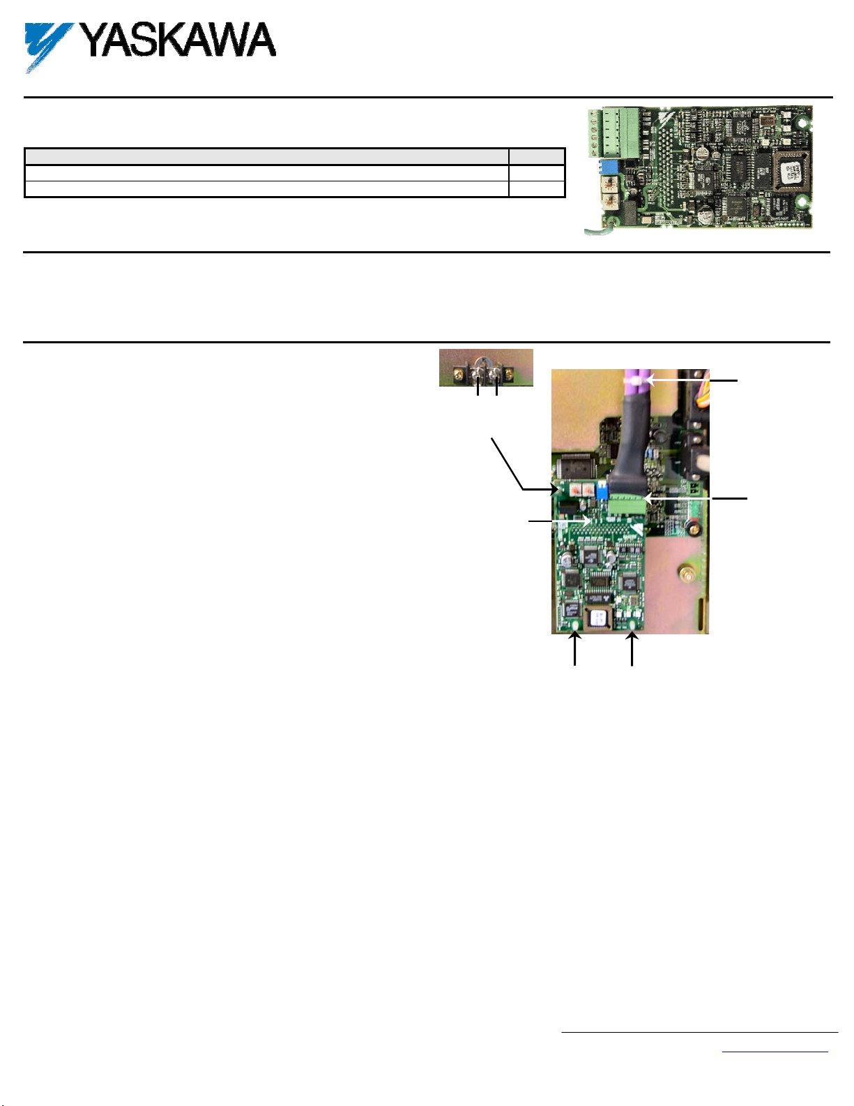
Attach the CM061 Profibus-DP Option (SI-P1 card) to the master control board.
Attach the CM061 Profibus-DP Option ground wire to the ground terminal
as shown. Make sure that the terminal is connected to a reliable, noise free
ground.
Connect the CM061 Profibus-DP Option card to the 2CN connector on the
master control board.
Secure the Profibus cable to the support with a tie wrap to provide strain
relief for the connector.
Attach the Profibus cable to the CM061 Profibus-DP Option card as shown
(this picture shows the standard Phoenix connector shrink-wrapped for
additional protection).
Fully engage the stand-offs in the mounting holes on the card.
Route the Profibus cable away from any power wires within the cabinet.
When outside of the cabinet, run the Profibus cable in its own conduit.
However, it may be run with low voltage signals such as feedback wiring.
SI-P1 Card
Ground Terminal
2CN Connector
Profibus Cable
Support
SI-P1 Card
Stand-offs
Attaching the CM061 Profibus-DP Option on a G5HHP master control board.
Yaskawa Electric America, Inc. – www.yaskawa.com
IG.G5HHP.12 Page 1 of 9
Date: 11/06/06 Rev: 06-11
Page 2
Connect the drive to the Profibus-DP communication network.
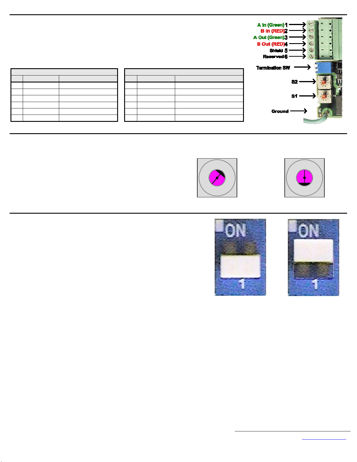
Connect the Profibus-DP network cable as shown in the figure to the right.
The cable shield must be contiguous between the beginning and end of any network segment. It is recommended
that the shield of the in cable and the out cable be twisted together. Do not connect the shield to the shield
connector, rather fold it back and secure it to the cable.
Use the pluggable connector that came with the CM061 Profibus-DP Option. The pluggable connector contains a
circuit board that remaps the terminal connections. Do not use an alternate connector. Damage to the CM061
Profibus-DP Option and/or associated network devices could be damaged if an alternate connector is used.
Plug Socket
Pin Description Definition Pin Description Definition
1 A In (Green) Negative 1 Reserved No Connection
2 B In (Red) Positive 2 Reserved No Connection
3 A Out (Green) Negative 3 A In/Out (Green) Negative
4 B Out (Red) Positive 4 B In/Out (Red) Positive
5 Shield Shield 5 Shield Shield
6 Reserved No Connection
Set the node address.
Set the node address for the drive by setting the 10‘s digit with S2
and the 1’s digit with S1.
All devices on the network must have unique node addresses. Check
the network layout to verify that the node address selected is unique
and falls between 3 – 99.
Node addresses 0 and 1 are typically reserved for master controllers.
Node address 2 is typically reserved for diagnostic equipment.
Set network termination.
If this drive is either the first or the last device on the network, including any PLC and/or
Profibus-DP Master, and active termination is not used, set the termination resistor switch to
ON.
If this device is not the first or last device on the network or active termination is used, set
the termination resistor switch to OFF.
Active termination is the recommended termination method and is required for networks
operating above 1.5Mbps. Active termination will eliminate the possibility of network failure
due to the removal of a terminated device.
The Siemens Profibus Terminator part number is 6ES7 972-0DA00-0AA0.
6 Reserved No Connection
Set address switch 2 to "1" Set address switch 1 to "5"
0
9
8
7
6
S2
Address = S2 (x10) + S1
Example: Set node address to 15
1
2
3
4
5
0
1
9
8
7
2
3
4
6
5
S1
OFF
Yaskawa Electric America, Inc. – www.yaskawa.com
IG.G5HHP.12 Page 2 of 9
Date: 11/06/06 Rev: 06-11
ON
Page 3
Configure the Profibus-DP network for the drive. Refer to the documentation included with the
Profibus configuration utility supplied with the Profibus-DP Master controller.
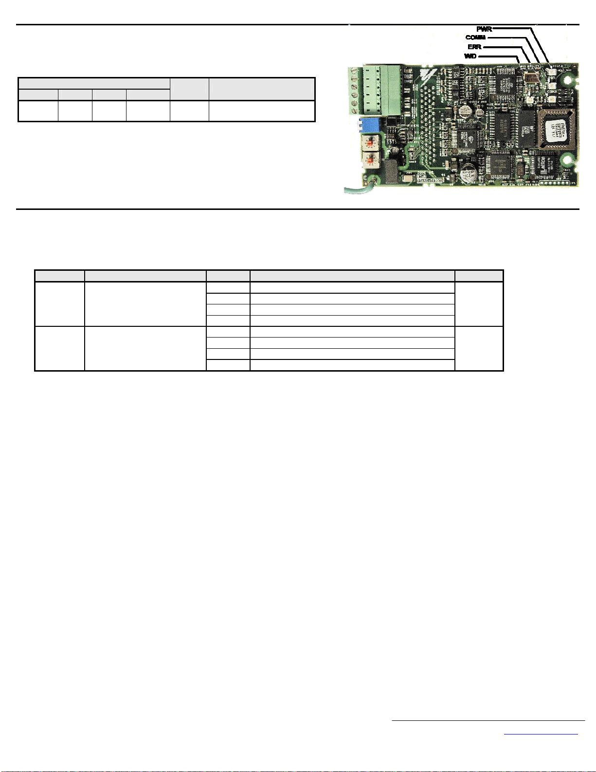
Apply power to the drive and verify that the diagnostic LEDs on the front of the CM061
Profibus-DP Option are in their correct state.
LED Display
PWR COM ERR WD
Solid
Green
Solid
Green
OFF
Flashing
Green
Content Cause
Normal Normal communication
Remove power from the drive and wait for the charge lamp to be completely extinguished. Wa it at least five additional minutes for the drive to be completely discharged.
Measure the DC bus voltage and verify that it is at a safe level.
Reinstall the operator keypad and all drive covers. Apply power to the drive.
Set parameters b1-01 and b1-02 to their appropriate values. Refer to the table below for available b1-01 and b1-02 values.
Parameter Function Data Description Default
0 Digital Operator
b1-01 Reference Source Select
b1-02 Run Command Source Select
1 Terminals
2 Built-in Modbus RTU Terminals
3
Option Card (CM061 Profibus-DP Option)
0 Digital Operator
1 Terminals
2 Built-in Modbus RTU Terminals
3
Option Card (CM061 Profibus-DP Option)
1
1
Yaskawa Electric America, Inc. – www.yaskawa.com
IG.G5HHP.12 Page 3 of 9
Date: 11/06/06 Rev: 06-11
Page 4

LED Status Indicators and Diagnostics
LED Display
PWR COM ERR WD
OFF OFF OFF OFF
Solid
Green
Solid
Green
Solid
Green
Solid
Green
Solid
Green
Solid
Green
OFF
OFF
OFF
Solid
Green
Solid
Green
Solid
Green
Solid
Red
Solid
Red
Flashing
Red
Flashing
Red
OFF
OFF
Solid
Red
Flashing
Red
Solid
Green
Solid
Green
Solid
Green
Flashing
Green
Content Cause Solution
Option is not powered
Power
OFF
CPU
Error
Drive
Error
Com
Error
Com
Error
CPU
Init
Normal Normal —
Poor connection to drive
Option unit CPU error
Error in Drive unit
Communication Failure
Communication Fault
Initialization • Wait until WD LED is flashing.
• Check the main circuit wiring on the drive.
• Cycle drive power.
• Turn of the drive power.
• Check the Profibus-DP Option connection to the drive 2CN
connector,
• Cycle drive power.
• Cycle drive power.
• Replace Profibus-DP Option if fault persists.
• Cycle drive power.
• Replace Profibus-DP Option if fault persists.
• Replace drive if fault persists.
• Check whether the address set in the Profibus-DP Master
differs from the address of the option unit.
• Check that the master is functioning properly.
• Check that the termination resistor is correctly connected to
the communication line.
• Check whether the communication line is correctly connected
(disconnected or poor connection).
• Check that the communication line is separated from the main
power line.
• Check whether the address is duplicated with any other
devices on the Profibus-DP network.
Yaskawa Electric America, Inc. – www.yaskawa.com
IG.G5HHP.12 Page 4 of 9
Date: 11/06/06 Rev: 06-11
Page 5

Profibus-DP Configuration
To simplify the drive configuration, the GSD file can be obtained at
www.yaskawa.com
Product, and Network Comms-Profibus. Then select the file
YASK00CA.GSD.
Load the GSD file, YASK00CA.GSD, into the proper directory for the
configuration tool used. Retrieve the GSD file from either
www.yaskawa.com
file is loaded.
Select the Profibus-DP INTER device when adding Yaskawa drives to the
Profibus configuration. See the figure to the right.
The CM061 Profibus-DP Option supports three configur ation options:
Extended Data 1 (32 words of input and output), Extended Data 2 (12 words
of input and output) and Basic Data (3 words of I/O). Refer to the Profibus-
DP Option Technical Manual (TM.AFD.12) for further information on
each configuration. See the figure to the right.
. Select Downloads, Browse, By Inverter Drives, By
or www.profibus.org to make sure that the latest GSD
Yaskawa Electric America, Inc. – www.yaskawa.com
IG.G5HHP.12 Page 5 of 9
Date: 11/06/06 Rev: 06-11
Page 6

Parameter Table
Name Addr Text Limits Default Cntrl Met __ Name Addr Text Limits Default Cntrl Met
A1-00 100 Language Select 0 ~ 1 0 b3-01 18E Speed Search Mode Select 0 ~ 1 0
A1-01 101 Access Level Select 0 ~ 4 2 b3-02 18F Speed Search Current Level 0 ~ 200 150
A1-02 102 Control Mode Select 0 ~ 3 0 b3-03 190 Speed Search Decel Time 0.1 ~ 10.0 10.0
A1-03 103 Initialization Select 0 ~ 3330 0 b4-01 192 Timer On Delay 0.0 ~ 300.0 0.0
A1-04 104 Password 0 ~ 9999 0 b4-02 193 Timer Off Delay 0.0 ~ 300.0 0.0
A1-05 105 Password 0 ~ 9999 0 b5-01 194 PID Mode Select 0 ~ 2 0
A2-01 106 User Parameter 01 180h ~ 0 b5-02 195 PID P Gain 0.00 ~ 25.00 1.00
A2-02 107 User Parameter 02 180h ~ 0 b5-03 196 PID I Time 0.0 ~ 360.0 1.0
A2-03 108 User Parameter 03 180h ~ 0 b5-04 197 PID I Limit 0.00 ~ 100.0 100.0
A2-04 109 User Parameter 04 180h ~ 0 b5-05 198 PID D Time 0.0 ~ 10.00 0.00
A2-05 10A User Parameter 05 180h ~ 0 b5-06 199 PID Limit 0.0 ~ 100.0 100
A2-06 10B User Parameter 06 180h ~ 0 b5-07 19A PID Offset -100. 0 ~ +100.0 0.0
A2-07 10C User Parameter 07 180h ~ 0 b5-08 19B PID Delay 0.00 ~ 10.00 0.00
A2-08 10D User Parameter 08 180h ~ 0 b6-01 19C Dwell Reference at Start 0.0 ~ 150.0 0.0
A2-09 10E User Parameter 09 180h ~ 0 b6-02 19D Dwell Time at Start 0.0 ~ 10.0 0.0
A2-10 10F User Parameter 10 180h ~ 0 b6-03 19E Dwell Reference at Stop 0.0 ~ 150.0 0.0
A2-11 110 User Parameter 11 180h ~ 0 b6-04 19F Dwell Time at Stop 0.0 ~ 10.0 0.0
A2-12 111 User Parameter 12 180h ~ 0 b7-01 1A0 Droop Gain 0.0 ~ 100.0 0.0 FV
A2-13 112 User Parameter 13 180h ~ 0 b7-02 1A1 Droop Delay 0.03 ~ 2.00 0.05 FV
A2-14 113 User Parameter 14 180h ~ 0 b8-01 1A2 Energy Savings Gain 0 ~ 100 80
A2-15 114 User Parameter 15 180h ~ 0 b8-02 1A3 Energy Savings Reference 0.0 ~ 150.0 0.0
A2-16 115 User Parameter 16 180h ~ 0 b9-01 1A4 Zero Servo Gain 0 ~ 100 5 FV
A2-17 116 User Parameter 17 180h ~ 0 b9-02 1A5 Zero Servo Completion Width 0 ~ 16383 10 FV
A2-18 117 User Parameter 18 180h ~ 0 C1-01 200 Accel Time 1 0.0 ~ 6000.0 30.0
A2-19 118 User Parameter 19 180h ~ 0 C1-02 201 Decel Time 1 0.0 ~ 6000.0 30.0
A2-20 119 User Parameter 20 180h ~ 0 C1-03 202 Accel Time 2 0.0 ~ 6000.0 30.0
A2-21 11A User Parameter 21 180h ~ 0 C1-04 203 Decel Time 2 0.0 ~ 6000.0 30.0
A2-22 11B User Parameter 22 180h ~ 0 C1-05 204 Accel Time 3 0.0 ~ 6000.0 30.0
A2-23 11C User Parameter 23 180h ~ 0 C1-06 205 Decel Time 3 0.0 ~ 6000.0 30.0
A2-24 11D User Parameter 24 180h ~ 0 C1-07 205 Accel Time 4 0.0 ~ 6000.0 30.0
A2-25 11E User Parameter 25 180h ~ 0 C1-08 207 Decel Time 4 0.0 ~ 6000.0 30.0
A2-26 11F User Parameter 26 180h ~ 0 C1-09 208 Fast Stop Time 0.0 ~ 6000.0 30.0
A2-27 120 User Parameter 27 180h ~ 0 C1-10 209 Accel/Decel Unit Select 0 ~ 1 0
A2-28 121 User Parameter 28 180h ~ 0 C1-11 20A Accel/Decel Switch Frequency 0.0 ~ 150.0 0.0
A2-29 122 User Parameter 29 180h ~ 0 C2-01 20B S-Curve Accel at Start 0.00 ~ 2.50 0.20
A2-30 123 User Parameter 30 180h ~ 0 C2-02 20C S-Curve Accel at End 0.00 ~ 2.50 0.20
A2-31 124 User Parameter 31 180h ~ 0 C2-03 20D S-Curve Decel at Start 0.00 ~ 2.50 0.20
A2-32 125 User Parameter 32 180h ~ 0 C2-04 20E S-Curve Decel at End 0.00 ~ 2.50 0.20
b1-01 180 Reference Source Select 0 ~ 3 1 C3-01 20F Slip Comp Gain 0.00 ~ 2.50 0.00
b1-02 181 Run Command Source Select 0 ~ 3 1 C3-02 210 Slip Comp Time 0 ~ 10000 2000
b1-03 182 Stopping Method Select 0 ~ 3 0 C3-03 211 Slip Comp Limit 0 ~ 250 200
b1-04 183 Reverse Prohibit Select 0 ~ 1 0 C3-04 212 Slip Comp Regen Select 0 ~ 1 0
b1-05 184 Zero Speed Mode Select 0 ~ 3 0 FV C3-05 242 Flux Select 0 ~ 1 0 OLV
b1-06 185 I/O Scan Time Select 0 ~ 1 1 C4-01 213 Torque Comp Gain 0.00 ~ 2.50 1.00
b1-07 186 Local/Remote Select 0 ~ 1 0 C4-02 214 Torque Comp Time 0 ~ 10000 1000
b2-01 187 DC Injection Start Freq uency 0.0 ~ 10.0 0.5 C5-01 215 ASR P Gain 0.00 ~ 300.00 20.00 w/ PG
b2-02 188 DC Injection Current Level 0 ~ 100 50 C5-02 216 ASR I Time 0.000 ~ 10.000 0.500 w/ PG
b2-03 189 DC Injection Time at Start 0.00 ~ 10.00 0.00 C5-03 217 ASR P Gain 2 0.00 ~ 300.00 20.00 w/ PG
b2-04 18A DC Injection Time at Stop 0.00 ~ 10.00 0.00 C5-04 218 ASR I Time 2 0.000 ~ 10.000 0.500 w/ PG
Yaskawa Electric America, Inc. – www.yaskawa.com
IG.G5HHP.12 Page 6 of 9
Date: 11/06/06 Rev: 06-11
Page 7

Name Addr Text Limits Default Cntrl Met __ Name Addr Text Limits Default Cntrl Met
C5-05 219 ASR Limit 0.0 ~ 20.0 5.0 V/f w/PG
C5-06 21A ASR Delay Time 0.000 ~ 0.500 0.004 FV
C5-07 21B ASR Switchover Frequency 0.0 ~ 150.0 0.0 FV
C5-08 241 ASR I Limit 0 ~ 400 400 FV
C6-01 21C Carrier Frequency Upper Limit 0.4 ~ 2.0 2.0
C6-02 21D Carrier Frequency Lower Limit 0.4 ~ 2.0 1.0
C6-03 21E Carrier Frequency Gain 00 ~ 99 36
C7-01 21F Hunting Prevention Select 0 ~ 1 1
C7-02 220 Hunting Prevention Gain 0.00 ~ 2.50 1.00
C8-08 22A AFR Gain 0.00 ~ 10.00 1.00 OLV
C8-09 22B AFR Time 0 ~ 200 50 OLV
C8-30 240 Carrier Frequency in Auto Tune 0 ~ 1 0 OLV
C9-04 24B CT/VT Operation Mode Select 0 ~ 1
d1-01 280 Frequency Reference 1 0.0 ~ 150.0 0.0
d1-02 281 Frequency Reference 2 0.0 ~ 150.0 0.0
d1-03 282 Frequency Reference 3 0.0 ~ 150.0 0.0
d1-04 283 Frequency Reference 4 0.0 ~ 150.0 0.0
d1-05 284 Frequency Reference 5 0.0 ~ 150.0 0.0
d1-06 285 Frequency Reference 6 0.0 ~ 150.0 0.0
d1-07 286 Frequency Reference 7 0.0 ~ 150.0 0.0
d1-08 287 Frequency Reference 8 0.0 ~ 150.0 0.0
d1-09 288 Jog Frequency Reference 0.0 ~ 150.0 6.0
d2-01 289 Frequency Reference Upper Limit 0.0 ~ 110.0 100.0
d2-02 28A Frequency Reference L ower Limit 0.0 ~ 109.0 0.0
d3-01 28B Jump Frequency 1 0.0 ~ 150.0 0.0
d3-02 28C Jump Frequency 2 0.0 ~ 150.0 0.0
d3-03 28D Jump Frequency 3 0.0 ~ 150.0 0.0
d3-04 28E Jump Bandwidth 0.0 ~ 20.0 1.0
d4-01 28F MOP Reference Memory Select 0 ~ 1 0
d4-02 290 Trim Control Level 0 ~ 100 10
d5-01 291 Torque Control Select 0 ~ 1 0 FV
d5-02 292 Torque Reference Filter 0 ~ 1000 0 FV
d5-03 293 Speed Limit Select 1 ~ 2 1 FV
d5-04 294 Speed Limit Value -120 ~ +120 0 FV
d5-05 295 Speed Limit Bias 0 ~ 120 10 FV
d5-06 296 Speed/Torque Switchover Time 0 ~ 1000 0 FV
E1-01 300 Input Voltage 360 ~ 460 460
E1-02 301 Motor Overload Curve Select 0 ~ 1 0
E1-03 302 V/f Pattern Select 0 ~ F F
E1-04 303 Maximum Output Frequency 50.0 ~ 150.0 60.0
E1-05 304 Maximum Output Voltage 0.0 ~ 510.0 460.0
E1-06 305 Base Frequency 0.0 ~ 150.0 60.0
E1-07 306 Mid Output Frequency A 0.0 ~ 150.0 3.0
E1-08 307 Mid Output Voltage A 0.0 ~ 510.0 27.6
E1-09 308 Minimum Output Frequency 0.0 ~ 150.0 1.5
E1-10 309 Minimum Output Voltage 0.0 ~ 510.0 13.8
E1-11 30A Mid Output Frequency B 0.0 ~ 150.0 0.0
E1-12 30B Mid Output Voltage B 0.0 ~ 510.0 0.0
E1-13 30C Base Voltage 0.0 ~ 510.0 0.0
E2-01 30E Motor Rated Current 80.0 ~ 1600.0 740.0
E2-02 30F Motor Rated Slip 0.00 ~ 20.0 0 1.30
E2-03 310 No-Load Current 0.0 ~ 2000.0 192.0
E2-04 311 Number of Motor Poles 2 ~ 48 4 w/ PG
E2-05 312 Motor Line-to-Line Resistance 0.000 ~ 65.000 0.010
E2-06 313 Leakage Inductance 0.0 ~ 30.0 5.0 OLV, FV
E2-07 314 Saturation Coefficient 1 0.00 ~ 0.50 0.50 OLV, FV
E2-08 315 Saturation Coefficient 2 0.00 ~ 0.75 0.75 OLV, FV
E2-09 316 Mechanical Loss 0.0 ~ 10.0 0.0 OLV, FV
E3-01 317 Motor 2 Control Mode Select 0 ~ 1 1
E4-01 318 Motor 2 Max Output Frequency 50.0 ~ 150.0 60.0
E4-02 319 Motor 2 Max O utput Voltage 0.0 ~ 510.0 460.0
E4-03 31A Motor 2 Base Frequency 0.0 ~ 150.0 60.0
E4-04 31B Motor 2 Mid Output Frequency A 0.0 ~ 150.0 3.0
E4-05 31C Motor 2 Mid Output Voltage A 0.0 ~ 510.0 27.6
E4-06 31D Motor 2 Min Output Frequency 0.0 ~ 150.0 1.5
E4-07 31E Motor 2 Min Output Voltage 0.0 ~ 510.0 13.8
E5-01 31F Motor 2 Rated Current 0.0 ~ 2000.0 740.0
E5-02 320 Motor 2 Rated Slip 0.00 ~ 20.00 1.30
E5-03 321 Motor 2 No-Load Current 0.0 ~ 2000.0 192.0
E5-05 323 Motor 2 L ine-to-Line Resistance 0.000 ~ 65.000 0.010
F1-01 380 Encoder (PG) PPR 0 ~ 60000 1024 w/ PG
F1-02 381 PG Feedback Loss Select 0 ~ 3 1 w/ PG
F1-03 382 PG Overspeed Select 0 ~ 3 1 w/ PG
F1-04 383 PG Deviation Select 0 ~ 3 3 w/ PG
F1-05 384 PG Rotation Select 0 ~ 1 0 w/ PG
F1-06 385 PG Output Monitor Ratio 1 ~ 132 1 w/ PG
F1-07 386 PG Integral Accel/Decel Select 0 ~ 1 0 V/f w/PG
F1-08 387 PG Overspeed Level 0 ~ 120 115 w/ PG
F1-09 388 PG Overspeed Time 0.0 ~ 2.0 0.0 w/ PG
F1-10 389 Speed Deviation Level 0 ~ 50 10 w/ PG
F1-11 38A Speed Deviation Delay Time 0.0 ~ 10.0 0.5 w/ PG
F1-12 38B PG Gear Teeth 1 0 ~ 1000 0 V/f w/PG
F1-13 38C PG Gear Teeth 2 0 ~ 1000 0 V/f w/PG
F1-14 397 PG Loss Detection Delay Time 0.0 ~ 10.0 2.0 w/ PG
F2-01 38D A1-14B Input Select 0 ~ 1 0
F3-01 38E DI-08/DI-16H2 Input Select 0 ~ 7 0
F4-01 38F AO-08/AO-12 Channel 1 Select 1 ~ 33 2
F4-02 390 AO-08/AO-12 Channel 1 Gain 0.00 ~ 2.50 1.00
F4-03 391 AO-08/AO-12 Channel 2 Select 1 ~ 33 3
F4-04 392 AO-08/AO-12 Channel 2 Gain 0.00 ~ 2.50 0.50
F5-01 393 DO-02C Channel 1 Select 0 ~ 37 0
F5-02 394 DO-02C Channel 2 Select 0 ~ 37 1
F6-01 395 DO-08 Output Select 0 ~ 1 0
F7-01 396 PO-36F Output Select 0 ~ 4 1
F8-01 398 SI-F/G E-15 Detection Select 0 ~ 3 1
F9-01 399 EF0 Fault Select 0 ~ 1 0
F9-02 39A EF0 Detection Select 0 ~ 1 0
F9-03 39B EF0 Response Select 0 ~ 3 1
F9-04 39C Trace Sample Time 0 ~ 60000 0
F9-06 39F BUS Fault Select 0 ~ 3 1
H1-01 400 DI Terminal 11 Function Select 0 ~ 77h 24
H1-02 401 DI Terminal 12 Function Select 0 ~ 77h 14
Yaskawa Electric America, Inc. – www.yaskawa.com
IG.G5HHP.12 Page 7 of 9
Date: 11/06/06 Rev: 06-11
Page 8

Name Addr Text Limits Default Cntrl Met __ Name Addr Text Limits Default Cntrl Met
H1-03 402 DI Terminal 13 Function Select 0 ~ 77h 3 L3-03 48A Stall Prevention Accel CHP Limit 0 ~ 100 50
H1-04 403 DI Terminal 14 Function Select 0 ~ 77h 4 L3-04 48B Stall Prevention Decel Select 0 ~ 2 1
H1-05 404 DI Terminal 15 Function Select 0 ~ 77h 6 L3-05 48C Stall Prevention Run Select 0 ~ 2 1
H1-06 405 DI Terminal 16 Function Select 0 ~ 77h 8 L3-06 48D Stall Prevention Run Level 30 ~ 20 0 160
H2-01 406 DO Terminal 53-57 Function 0 ~ 37h 0 L4-01 490 Speed Agree Level 0.0 ~ 150.0 0.0
H2-02 407 DO Terminal 19-50 Function 0 ~ 37h 1 L4-02 491 Speed Agree Width 0.0 ~ 20.0 2.0
H2-03 408 DO Terminal 20-50 Function 0 ~ 37h 2 L4-03 492 Speed Agree Detection Level 0.0 ~ 150.0 0.0
H3-01 409 AI Terminal 36 Signal Type Select 0 ~ 1 0 L4-04 493 Speed Agree Detection Width 0.0 ~ 20.0 2.0
H3-02 40A AI Terminal 36 Gain 0.0 ~ 100.0 100.0 L4-05 494 Reference Loss Detection Select 0 ~ 1 0
H3-03 40B AI Terminal 36 Bias -100.0 ~ +100.0 0.0 L5-01 495 Number of Auto Restarts Select 0 ~ 10 0
H3-04 40C AI Terminal 42 Signal Type Select 0 ~ 1 0 L5-02 496 Auto Restart Fault Select 0 ~ 1 0
H3-05 40D AI Terminal 42 Function Select 1 ~ 1Fh 0 L6-01 498 Torque Detection Select 1 0 ~ 4 0
H3-06 40E AI Terminal 42 Gain 0.0 ~ 100.0 100.0 L6-02 499 Torque Detection Level 1 0 ~ 300 150
H3-07 40F AI Terminal 42 Bias -100.0 ~ +100.0 0.0 L6-03 49A Torque Detection Time 1 0.0 ~ 10.0 0.1
H3-08 410 AI Terminal 39 Signal Type Select 0 ~ 2 2 L6-04 49B Torque Detection Select 2 0 ~ 4 0
H3-09 411 AI Terminal 39 Function Select 1 ~ 1Fh 1F L6-05 49C Torque Detection Level 2 0 ~ 300 150
H3-10 412 AI Terminal 39 Gain 0.0 ~ 100.0 100.0 L6-06 49D Torque Detection Time 2 0.0 ~ 10.0 0.1
H3-11 413 AI Terminal 39 Bias -100.0 ~ +100.0 0.0 L7-01 49E Forward Torque Limit 0 ~ 300 200 OLV, FV
H3-12 414 AI Terminals Filter Time 0.00 ~ 2.00 0.00 L7-02 49F Reverse Torque Limit 0 ~ 300 200 OLV, FV
H4-01 415 AO Terminal 45 Function Select 1 ~ 33h 2 L7-03 4A0 Forward Regen Torque Limit 0 ~ 300 200 OLV, FV
H4-02 416 AO Terminal 45 Gain 0.00 ~ 2.50 1.00 L7-04 4A1 Reverse Regen Torque Limit 0 ~ 300 200 OLV, FV
H4-03 417 AO Terminal 45 Bias -10 ~ +10 0.0 L8-01 4A4 DB Resistor Protection Select 0 ~ 1 0
H4-04 418 AO Terminal 48 Function Select 1 ~ 33h 3 L8-02 4A5 OH Pre-Alarm Level 50 ~ 110 95
H4-05 419 AO Terminal 48 Gain 0.00 ~ 2.50 0.50 L8-03 4A6 OH Pre-Alarm Select 0 ~ 3 3
H4-06 41A AO Terminal 48 Bias -10.0 ~ +10.0 0.0 L8-05 4A8 Input Phase Loss Select 0 ~ 1 0
H4-07 41B AO Term inal Signal Type Select 0 ~ 1 0 L8-07 4AA Output Phase Loss Select 0 ~ 1 1
H5-01 41C Modbus Node Address 0 ~ 20 1F o1-01 500 User Monitor Select 4 ~ 33 6
H5-02 41D Modbus Baud Rate Select 0 ~ 3 3 o1-02 501 Power-On Monitor Select 1 ~ 4 1
H5-03 41E Modbus Parity Select 0 ~ 2 0 o1-03 502 Display Scaling Select 0 ~ 39999 0
H5-04 41F Serial Fault Stopping Method 0 ~ 3 3 o1-04 503 V/f Pattern Unit Select 0 ~ 1 0
H5-05 420 Serial Fault Detection Select 0 ~ 1 1 o1-05 504 Modbus Address Display Select 0 ~ 1 6
L1-01 480 Motor Overload Fault Select 0 ~ 1 1 o2-01 505 Local/Remote Key Select 0 ~ 1 1
L1-02 481 Motor Overload Time Constant 0.1 ~ 5.0 1.0 o2-02 506 Stop Key Function Select 0 ~ 1 1
L2-01 482 Power Loss Detection Select 0 ~ 2 0 o2-03 507 User Initialize Default Select 0 ~ 2 0
L2-02 483 Power Loss Ride-Thru Time 0.0 ~ 2.0 1.0 o2-04 508 Drive Model kVA Select 0 ~ FFh 4400
L2-03 484 Minimum Baseblock Time 0.0 ~ 25.5 10.0 o2-05 509 Operator MOP Function Select 0 ~ 1 0
L2-04 485 Voltage Recovery Ramp Time 0.0 ~ 5.0 3.0 o2-06 50A Operator Detection Select 0 ~ 1 1
L2-05 486 Undervoltage Detection Level 300 ~ 420 380 o2-07 50B Elapsed Time Initial Setting 0 ~ 65535 0
L2-06 487 KEB Decel Time 0.0 ~ 100.0 0.0 o2-08 50C Elapsed Time Function Select 0 ~ 1 0
L3-01 488 Stall Prevention Ac cel Select 0 ~ 2 1 o2-09 50D Initialization Mode Select 0 ~ 2 1
L3-02 489 Stall Prevention Accel Level 0 ~ 200 150
Note: 1: Default values were determined through a 2-wire reset on drive model 4400. Default values may be different for different drive models.
2: Use address FFDDh for the ACCEPT command.
3: Use address FFFDh for the ENTER command.
CAUTION!
Limit the use of the ENTER command. The drive has limited writes when using
the ENTER command.
Yaskawa Electric America, Inc. – www.yaskawa.com
IG.G5HHP.12 Page 8 of 9
Date: 11/06/06 Rev: 06-11
Page 9

Profibus-DP® Option Card
CM061 (SI-P1)
Copies of this Installation Guide along with all technical manuals in “.pdf” format and support files may be obtained from either the CD supplied with the drive or from
www.yaskawa.com
www.profibus.org
. Printed copies of any Yaskawa manual may be obtained by contacting the nearest Yaskawa office. Information on Profibus-DP may be obtained from
.
Reference documents:
Profibus-DP Technical Manual – TM.AFD.12
G5HHP Technical Manual – TM.G5HHP.01
GPD515/G5 Modbus
®
Technical Manual – TM.4025
®
Modbus
is a registered trademark of Schneider Automation, Inc.
GPD is a trademark of Yaskawa, Inc.
®
Profibus
and Profibus-DP® are registered trademarks of Profibus Nutzerorganisation e.V.
YASKAWA ELECTRIC AMERICA, INC.
Drives Division
16555 West Ryerson Road, New Berlin, WI 53151, U.S.A.
Phone: (800) YASKAWA (800-927-5292) Fax: (262) 782-3418
Internet: http://www.yaskawa.com
YASKAWA ELECTRIC AMERICA, INC.
Chicago-Corporate Headquarters
2121 Norman Drive South, Waukegan, IL 60085, U.S.A.
Phone: (800) YASKAWA (800-927-5292) Fax: (847) 887-7310
Internet: http://www.yaskawa.com
MOTOMAN INC.
805 Liberty Lane, West Carrollton, OH 45449, U.S.A.
Phone: (937) 847-6200 Fax: (937) 847-6277
Internet: http://www.motoman.com
YASKAWA ELECTRIC CORPORATION
New Pier Takeshiba South Tower, 1-16-1, Kaigan, Minatoku, Tokyo, 105-0022, Japan
Phone: 81-3-5402-4511 Fax: 81-3-5402-4580
Internet: http://www.yaskawa.co.jp
YASKAWA ELETRICO DO BRASIL COMERCIO LTDA.
Avenida Fagundes Filho, 620 Bairro Saude Sao Paolo-SP, Brasil CEP: 04304-000
Phone: 55-11-5071-2552 Fax: 55-11-5581-8795
Internet: http://www.yaskawa.com.br
YASKAWA ELECTRIC EUROPE GmbH
Am Kronberger Hang 2, 65824 Schwalbach, Germany
Phone: 49-6196-569-300 Fax: 49-6196-888-301
MOTOMAN ROBOTICS AB
Box 504 S38525, Torsas, Sweden
Phone: 46-486-48800 Fax: 46-486-41410
MOTOMAN ROBOTEC GmbH
Kammerfeldstrabe 1, 85391 Allershausen, Germany
Phone: 49-8166-900 Fax: 49-8166-9039
YASKAWA ELECTRIC UK LTD.
1 Hunt Hill Orchardton Woods Cumbernauld, G68 9LF, Scotland, United Kingdom
Phone: 44-12-3673-5000 Fax: 44-12-3645-8182
YASKAWA ELECTRIC KOREA CORPORATION
Paik Nam Bldg. 901 188-3, 1-Ga Euljiro, Joong-Gu, Seoul, Korea
Phone: 82-2-776-7844 Fax: 82-2-753-2639
YASKAWA ELECTRIC (SINGAPORE) PTE. LTD.
Head Office: 151 Lorong Chuan, #04-01, New Tech Park Singapore 556741, Singapore
Phone: 65-282-3003 Fax: 65-289-3003
TAIPEI OFFICE (AND YATEC ENGINEERING CORPORATION)
10F 146 Sung Chiang Road, Taipei, Taiwan
Phone: 886-2-2563-0010 Fax: 886-2-2567-4677
YASKAWA JASON (HK) COMPANY LIMITED
Rm. 2909-10, Hong Kong Plaza, 186-191 Connaught Road West, Hong Kong
Phone: 852-2803-2385 Fax: 852-2547-5773
BEIJING OFFICE
Room No. 301 Office Building of Beijing International Club,
21 Jianguomanwai Avenue, Beijing 100020, China
Phone: 86-10-6532-1850 Fax: 86-10-6532-1851
SHANGHAI OFFICE
27 Hui He Road Shanghai 200437 China
Phone: 86-21-6553-6600 Fax: 86-21-6531-4242
SHANGHAI YASKAWA-TONJI M & E CO., LTD.
27 Hui He Road Shanghai 200437 China
Phone: 86-21-6533-2828 Fax: 86-21-6553-6677
BEIJING YASKAWA BEIKE AUTOMATION ENGINEERING CO., LTD.
30 Xue Yuan Road, Haidian, Beijing 100083 China
Phone: 86-10-6232-9943 Fax: 86-10-6234-5002
SHOUGANG MOTOMAN ROBOT CO., LTD.
7, Yongchang-North Street, Beijing Economic & Technological Development Area,
Beijing 100076 China
Phone: 86-10-6788-0551 Fax: 86-10-6788-2878
YEA, TAICHUNG OFFICE IN TAIWAIN
B1, 6F, No.51, Section 2, Kung-Yi Road, Taichung City, Taiwan, R.O.C.
Phone: 886-4-2320-2227 Fax:886-4-2320-2239
Data subject to change without notice.
Yaskawa Electric America, Inc. – www.yaskawa.com
IG.G5HHP.12 Page 9 of 9
Date: 11/06/06 Rev: 06-11
 Loading...