

Page 1
Unpack the
present and undamaged.
LonWorks Option Card
Installation Guide (IG.AFD.20) 1
Verify that the drive is one of the following series: E7, P7, F7, or G7.
The
Apply power to the drive or panel and verify that they function correctly.
This includes running the drive through the drive keypad (or the door
mounted Bypass controls, in case of E7B, E7L, or P7B. Refer to the
appropriate technical manual for information on connections and
operation.
Remove power and wait for the drive charge lamp to be completely
extinguished. Measure and verify the drive’s DC BUS voltage to be at a
safe level.
LONW
ORKS
Option Kit
Part Qty.
(UTC000057)
LonWorks Option Card
and verify that all components are
is only compatible with these drive series.
1
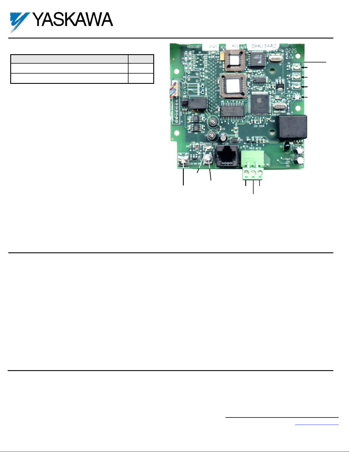
LONWORKS® Option Card
CM048
LEDs
PWR
RECEIVE
TRANSMIT
FAULT
Remove the operator keypad and drive cover(s).
Remove the operator keypad by depressing the tab on the right
side of the keypad and then pulling it out. In E7B, E7C, E7L, P7B,
P7C, or F7C, the keypad may already have been removed and
mounted on the enclosure door.
Remove the drive’s front cover until the entire control card is
exposed. The number of covers and the removal procedure varies
by drive series and capacity. Consult the drive’s technical manual
for details. In E7B, E7C, E7L, P7B, P7C, or F7C, the keypad may
already have been removed and mounted on the enclosure door.
Remove the option card hold-down plug on the left side of the
drive case by carefully compressing the top and bottom until it
becomes free of its holder and then pulling it out.
Mount the
Align the 2CN connector on the back of the
Press the
Standard Connection - Route the four wires from the
E7L Connection - Route the four wires from the
A noise free ground is essential for continuous, stable communications. DO NOT USE THE GROUND TERMINALS LOCATED ON THE DRIVE’S
Standard Termination - Set the Termination Switch S1-1 to ON as shown below. This is independent of whether the drive is the first or last device on
E7L Termination - Set the Termination Switch S1 to ON. This is independent of whether the drive is the first or last device on the
LONW
ORKS
Option Card
the two standoffs on the front of the drive’s control board with the two holes on the right side of the
have locked into their appropriate holes.
R+, R-, S+ and S- terminals on the I/O terminal assembly as shown below.
typically mounted on the left inside wall of the E7L enclosure. Connect the wires as shown below.
TERMINAL BOARD OR CHASSIS. If an external, noise free ground is available, connect a ground wire from the ground terminal on the
option Card
the
LonWorks Option Card
to the ground. If no noise free ground is available, leave the ground terminal on the
LonWorks
network.
on the drive.
LonWorks Option Card
firmly onto the drive’s 2CN connector and standoffs until the 2CN connector is fully seated and the drive standoffs
LonWorks Option Card
LonWorks Option Card
with its mating 2CN connector on the front of the drive’s control board. Align
SERVICE
LED
Ground
Terminal
along the left side of the control board and connect them directly to the
to terminal board TB4 on the E7L control card. The E7L control board is
SERVICE
Button
RJ45
net
net
A
B
shield
LONW
ORKS
Option Card.
LonWorks Option Card
LonWorks
un-terminated.
LonWorks
network.
Yaskawa Electric America, Inc. – www.yaskawa.com
IG.AFD.20, Page 1 of 5
Date: 03/02/2012, Rev: 12-03
Page 2
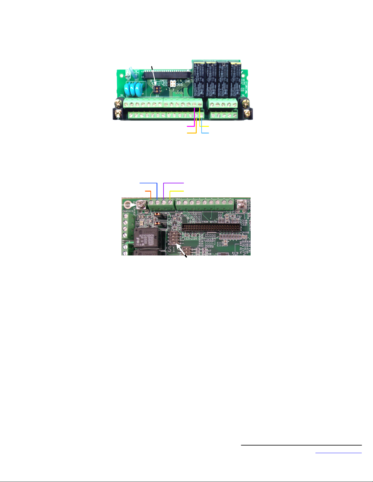
Termination SW
ON
R+ (Purple)
S+ (Orange)
Standard Drive Connection
S- (Blue) R+ (Purple)
S+ (Orange)
R- (Yellow)
Termination SW to ON
E7L Connection
R- (Yellow)
S- (Blue)
Yaskawa Electric America, Inc. – www.yaskawa.com
IG.AFD.20, Page 2 of 5
Date: 03/02/2012, Rev: 12-03
Page 3

Setting the drive parameters
Remove power from the drive and wait for the charge lamp to be completely extinguished. Wait at least five additional minutes for the drive to be
completely discharged. Measure the DC BUS voltage and verify that it is at a safe level.
Reinstall the operator keypad and all drive covers. Apply power to the drive.
Set parameter A1-01 to 2, Advanced.
Set parameters b1-01 and b1-02 to their appropriate values. Refer to the table below for available b1-01 and b1-02 values. Reference Selection
and Operation Method Selection can have different values depending on the application. To control both frequency and run/stop over the network,
set both b1-01 and b1-02 to 2, Serial Communications.
Set parameter H5-01 to 1F (31)
Set parameter H5-02 to 3, 9600 baud
Set parameter H5-03 to 0, No Parity
Set parameter H5-06 to 5, 5ms transmission wait
Set parameter H5-07 to 0, Disabled
Set parameter H5-08 to 0, MODBUS
Parameters H5-04 (Stopping Method at Communications Fault), H5-05 (Serial Fault Detection) and H5-09 (CE Detect Time) should be set according
to the desired drive performance during a communications timeout or failure.
After all drive parameters have been set, power cycle the drive. Communications parameters will not take affect until power has been removed from
the drive until the charge lamp has been extinguished and restored.
For E7L or E7B Bypass-Panel applications, refer to the parameter table and electrical schematic accompanying the unit for parameter and DIP-
switch settings.
Parameter Function Data +/- Limits - Description Default
0 Operator
A1-01 Access Level
1 User
2
2 Advanced
0 Digital Operator
1 Terminals
B1-01 Reference Selection
2 Serial Communication (LONWORKS)
1
3 Option PCB
4 Pulse Input
0 Digital Operator
1 Terminals
B1-02 Operation Method Selection
2 Serial Communication (LONWORKS)
1
3 Option PCB
H5-01 Serial Communications Address 1F 0 – 1F 1F
0 1200 baud
1 2400 baud
H5-02 Serial Baud Rate Select
2 4800 baud
3
3 9600 baud (LONWORKS)
4 19200 baud
ONWORKS)
0
H5-03 Serial Parity Select
0 None (L
1 Even parity
2 Odd parity
H5-06 Transmit Wait
H5-07 RTS Control Select
H5-08 Protocol Select
5 – 65ms 5
5
0 Disabled (L
ONWORKS)
1 Enabled
0 MODBUS (L
ONWORKS)
1 N2 (Metasys)
2 P1 (APOGEE)
0
0
Yaskawa Electric America, Inc. – www.yaskawa.com
IG.AFD.20, Page 3 of 5
Date: 03/02/2012, Rev: 12-03
Page 4

Connect to the
r
Connect the network to the
Network Identification and Node Configuration
LONW
The
option has not been installed on the network. On power up, an un-configured node can be recognized by the SERVICE LED blinking at 2Hz.
Network identification is accomplished with an installation tool. Unique network identities are established by pairing “logical” addresses with a device’s
48-bit Neuron ID.
SERVICE Button
Each option card has a Service Button. If using a configuration tool utilizing this feature, press the Service Button when prompted to do so. When
pressed, a broadcast message is sent which contains the Neuron ID and program ID. This uniquely identifies the node on the network. This method
works best for small networks or with portable installation tools.
Find and Wink
When it is impractical to press each node’s Service Button for installation (e.g. in large networks or a node is physically enclosed), the “find and
wink” installation method is useful. With this method, the installation tool queries the network for all unconfigured nodes. Nodes respond with their
Neuron ID and a logical address is assigned. A “wink” command can then be sent to each logical address. In response to this command, the
TRANSMIT and RECEIVE LED’s will blink rapidly for several seconds. In this manner, the exact physical location of each node can be identified.
Reclaiming a Node
A node can be “reclaimed”, or returned to its unconfigured state, as follows:
Remove power from the drive and wait for the charge lamp to be completely extinguished.
Press and hold the Service Button.
Re-apply drive power, continuing to press and hold the Service Button.
LonWorks
ORKS
Option Card
network.
LONW
ORKS
Option Card
is shipped unconfigured. This implies that the application is loaded and communications parameters are defined but the
as shown.
RJ45 Socket
N
e
t
A
N
S
e
H
t
L
B
D
After approximately 5 seconds, the SERVICE LED should begin flashing at a 0.5 Hz rate, indicating the unconfigured state. This procedure
sets both domain table entries to “undefined” and sets the channel ID to 0.
12345678
N
N
E
E
T
T
A
B
LED Status Indicators and Diagnostics
LED Display
PWR Receive Transmit Fault Service
OFF OFF OFF OFF OFF Power not supplied
ON BLINK BLINK BLINK OFF
ON ON OFF Communications Loss
ON FLASH OFF OFF Normal communications
ON FLASH OFF OFF Normal communications
BLINK
0.5Hz
FLASH
1sON_2sOFF_ContON
Condition Solution
Option is Not Configured
Application missing
Communications not
established
• Configure Option
• Download application image file
• Assign network Identity
• Check that drive has power
• Check option card seating in CN2 connector
• Check drive parameters (refer to table above)
• Check connection between option and drive
• Check network cable connections
Flash each time serial task is complete
Approximately 0.5Hz when drive is at STOP
Approximately 1.0Hz when drive RUN is active
Flash for every 5 netwo
k variables updates
Yaskawa Electric America, Inc. – www.yaskawa.com
IG.AFD.20, Page 4 of 5
Date: 03/02/2012, Rev: 12-03
Page 5

LONWORKS ® Option Card
CM048
Copies of this Installation Guide along with all technical manuals in PDF format and support files may be obtained from either the CD supplied with the drive
or from www.yaskawa.com
may be obtained at
www.echelon.com
. Printed copies of manuals may be obtained by contacting the Yaskawa Help Desk at 800-927-5292. Information on
LonWorks
Reference documents:
E7 Technical Manual – TM.E7.02
P7 Technical Manual – TM.P7.02
F7 Technical Manual – TM.F7.02
G7 Technical Manual – TM.G7.01
F7 Parameter Access Technical Manual – TM.F7.11
MODBUS
LonWorks
YASKAWA ELECTRIC AMERICA, INC.
Drives Division
16555 W. Ryerson Rd., New Berlin, WI 53151, U.S.A.
Phone: (800) YASKAWA (927-5292) Fax: (847) 887-7310
Internet: http://www.yaskawa.com
YASKAWA ELECTRIC AMERICA, INC.
Chicago-Corporate Headquarters
2121 Norman Drive South, Waukegan, IL 60085, U.S.A.
Phone: (800) YASKAWA (800-927-5292) Fax: (847) 887-7310
Internet: http://www.yaskawa.com
MOTOMAN INC.
805 Liberty Lane, West Carrollton, OH 45449, U.S.A.
Phone: (937) 847-6200 Fax: (937) 847-6277
Internet: http://www.motoman.com
YASKAWA ELECTRIC CORPORATION
New Pier Takeshiba South Tower, 1-16-1, Kaigan, Minatoku, Tokyo, 105-0022, Japan
Phone: 81-3-5402-4511 Fax: 81-3-5402-4580
Internet: http://www.yaskawa.co.jp
YASKAWA ELETRICO DO BRASIL COMERCIO LTDA.
Avenida Fagundes Filho, 620 Bairro Saude Sao Paolo-SP, Brasil CEP: 04304-000
Phone: 55-11-5071-2552 Fax: 55-11-5581-8795
Internet: http://www.yaskawa.com.br
YASKAWA ELECTRIC EUROPE GmbH
Am Kronberger Hang 2, 65824 Schwalbach, Germany
Phone: 49-6196-569-300 Fax: 49-6196-888-301
MOTOMAN ROBOTICS AB
Box 504 S38525, Torsas, Sweden
Phone: 46-486-48800 Fax: 46-486-41410
MOTOMAN ROBOTEC GmbH
Kammerfeldstrabe 1, 85391 Allershausen, Germany
Phone: 49-8166-900 Fax: 49-8166-9039
YASKAWA ELECTRIC UK LTD.
1 Hunt Hill Orchardton Woods Cumbernauld, G68 9LF, Scotland, United Kingdom
Phone: 44-12-3673-5000 Fax: 44-12-3645-8182
®
is a registered trademark of Schneider Automation, Inc.
®
is a registered trademark of Echelon Corporation.
YASKAWA ELECTRIC KOREA CORPORATION
Paik Nam Bldg. 901 188-3, 1-Ga Euljiro, Joong-Gu, Seoul, Korea
Phone: 82-2-776-7844 Fax: 82-2-753-2639
YASKAWA ELECTRIC (SINGAPORE) PTE. LTD.
Head Office: 151 Lorong Chuan, #04-01, New Tech Park Singapore 556741, Singapore
Phone: 65-282-3003 Fax: 65-289-3003
TAIPEI OFFICE (AND YATEC ENGINEERING CORPORATION)
10F 146 Sung Chiang Road, Taipei, Taiwan
Phone: 886-2-2563-0010 Fax: 886-2-2567-4677
YASKAWA JASON (HK) COMPANY LIMITED
Rm. 2909-10, Hong Kong Plaza, 186-191 Connaught Road West, Hong Kong
Phone: 852-2803-2385 Fax: 852-2547-5773
BEIJING OFFICE
Room No. 301 Office Building of Beijing International Club,
21 Jianguomanwai Avenue, Beijing 100020, China
Phone: 86-10-6532-1850 Fax: 86-10-6532-1851
SHANGHAI OFFICE
27 Hui He Road Shanghai 200437 China
Phone: 86-21-6553-6600 Fax: 86-21-6531-4242
SHANGHAI YASKAWA-TONJI M & E CO., LTD.
27 Hui He Road Shanghai 200437 China
Phone: 86-21-6533-2828 Fax: 86-21-6553-6677
BEIJING YASKAWA BEIKE AUTOMATION ENGINEERING CO., LTD.
30 Xue Yuan Road, Haidian, Beijing 100083 China
Phone: 86-10-6232-9943 Fax: 86-10-6234-5002
SHOUGANG MOTOMAN ROBOT CO., LTD.
7, Yongchang-North Street, Beijing Economic & Technological Development Area,
Beijing 100076 China
Phone: 86-10-6788-0551 Fax: 86-10-6788-2878
YEA, TAICHUNG OFFICE IN TAIWAIN
B1, 6F, No.51, Section 2, Kung-Yi Road, Taichung City, Taiwan, R.O.C.
Phone: 886-4-2320-2227 Fax: 886-4-2320-2239
Data subject to change without notice
Yaskawa Electric America, Inc. – www.yaskawa.com
IG.AFD.20, Page 5 of 5
Date: 03/02/2012, Rev: 12-03
 Loading...