

Page 1

YASKAWA AC Drive GA700
High Performance Type
Initial Steps
Type: CIPR-GA70Cxxxxxxxx
Models: 200 V class: 0.55 to 110 kW
400 V class: 0.55 to 355 kW
To properly use the product, read this manual thoroughly and retain for easy
reference, inspection, and maintenance. Ensure the end user receives this
manual.
MANUAL NO. TOEP C710617 17D
Initial Steps
EN
Page 2
1 General Information
1 General Information
Do not use this manual as a replacement for the Technical Manual. The products and specifications given in this
manual and the manual contents can change without notice to make the product and manual better. Be sure to
always use the most recent version of this manual. Use the manual for the correct installation, wiring, adjustment,
and operation of this product.
This manual is available for download on our documentation website. Refer to the back page of this manual.
2 Qualifications for the Intended User
Yaskawa created this manual for electrical specialists and engineers who have experience with AC drive
installation, adjustment, repair, inspection, and parts replacement. Persons without technical training, minors,
persons with disabilities or mental problems, persons with perception problems, and persons with pacemakers
must not use or operate this product.
3 Safety
Read the safety guidelines carefully before installing, wiring, or operating this product.
◆ Explanation of Signal Words
DANGER
WARNING
CAUTION
NOTICE
Indicates a hazardous situation, which, if not avoided, will cause death or serious injury.
Indicates a hazardous situation, which, if not avoided, could cause death or serious injury.
Indicates a hazardous situation, which, if not avoided, could cause minor or moderate injury.
Indicates a property damage message.
◆ General Safety Instructions
Yaskawa Electric manufactures and supplies electronic components for a variety of industrial applications. The
selection and application of Yaskawa products is the responsibility of the designer of the equipment or the
customer that assembles the final product. Yaskawa is not responsible for how our products are incorporated into
the final system design. In all cases, Yaskawa products should not be incorporated into a product or design as the
exclusive or sole safety control function. All control functions are designed to dynamically detect failures and
operate safely without exception. All products that are designed to incorporate parts manufactured by Yaskawa
must be provided to the end user and include proper warnings and instructions regarding their safe use and
operation. All warnings from Yaskawa must be promptly issued to the end user. Yaskawa offers warranties only
for the quality of our products, in compliance with standards and specifications that are described in the manual.
Yaskawa does not offer other warranties, either explicit or implied. Injuries, property damage, and lost business
opportunities caused by improper storage or handling and negligence oversight on the part of your company or
your customers will void Yaskawa’s warranty for the product.
Note:
Failure to obey the safety messages in the manual can cause serious injury or death. Yaskawa is not responsible for injuries or damage to
equipment caused by ignoring the safety messages.
• Read this manual carefully when mounting, operating, and repairing AC drives.
• Obey all warnings, cautions, and notices.
• Approved personnel must perform all work.
• Install the drive in an area with these conditions.
DANGER
servicing, disconnect all power to the equipment and wait for the time specified on the warning label at a minimum. The internal
capacitor stays charged after the drive is de-energized. The charge indicator LED extinguishes when the DC bus voltage
decreases below 50 Vdc. To prevent electric shock, always wait for at least the amount of time indicated on the warning labels.
When all indicators are OFF, remove the covers before measuring for dangerous voltages to make sure that the drive is safe.
Failure to obey will cause death or serious injury.
WARNING
power supply wiring to main circuit input terminals R/L1, S/L2, and T/L3. Failure to obey can cause death or serious injury.
WARNING
cause death or serious injury from falling equipment.
Electrical Shock Hazard. Do not examine, connect, or disconnect wiring on an energized drive. Before
Fire Hazard. Do not connect power supply wiring to drive output terminals U/T1, V/T2, and W/T3. Connect
Crush Hazard. Only approved personnel can operate a crane or hoist to move the drive. Failure to obey can
EN 2 YASKAWA ELECTRIC TOEP C710617 17D YASKAWA AC Drive GA700 Initial Steps
Page 3
3 Safety
WARNING
death or serious injury and will void warranty. Yaskawa is not responsible for changes to the product made by the user.
WARNING
repair the drive. Failure to obey can cause death or serious injury.
WARNING
cause death or serious injury from incorrect equipment grounding.
WARNING
Tighten loose clothing and remove all metal objects such as watches or rings. Failure to obey can cause death or serious injury.
WARNING
than 3.5 mA. The IEC/EN 61800-5-1: 2007 standard specifies that users must wire the power supply to automatically turn off
when the protective ground wire disconnects. Users can also connect a protective ground wire that has a minimum crosssectional area of 10 mm
injury.
WARNING
before starting Auto-Tuning. The drive and motor can start suddenly during Auto-Tuning and cause death or serious injury.
WARNING
machine area and attach covers, couplings, shaft keys, and machine loads before energizing the drive. Failure to obey can
cause death or serious injury.
WARNING
sure that the drive rated voltage aligns with the power supply voltage before energizing the drive. Failure to obey can cause
death or serious injury.
WARNING
near flammable or combustible materials. Attach the drive to metal or other noncombustible material. Failure to obey can cause
death or serious injury.
WARNING
tight can cause incorrect operation and damage to the drive. Incorrect connections can also cause death or serious injury from
fire.
WARNING
Tightening screws at an angle outside of the specified range can cause damage the terminal block or start a fire if the
connection is loose.
WARNING
cause death or serious injury from falling equipment.
WARNING
death or serious injury.
WARNING
protection against contact when using a residual current operated protective device or monitoring device as specified by IEC/EN
60755. The drive can cause a residual current with a DC component in the protective earthing conductor. Failure to obey can
cause death or serious injury.
WARNING
C to comply with the EMC Directive before turning on the EMC filter or if there is high resistance grounding. Failure to obey can
cause death or serious injury.
WARNING
blows a fuse or trips an RCM/RCD. Wait for the time specified on the warning label at a minimum and make sure that all
indicators are OFF. Then check the wiring and peripheral device ratings to find the cause of the problem. Contact Yaskawa
before energizing the drive or peripheral devices if the cause is not known. Failure to obey can cause death or serious injury
and damage to the drive.
WARNING
manual. The drive is suited for circuits that supply not more than 100,000 RMS symmetrical amperes, 240 Vac maximum (200 V
Class), 480 Vac maximum (400 V Class). Failure to obey can cause death or serious injury.
CAUTION
moving the drive. Failure to obey can cause minor to moderate injury.
CAUTION
sure that the heatsink is cool to replace the cooling fans. Failure to obey can cause minor to moderate injury.
NOTICE
to obey can cause ESD damage to the drive circuitry.
NOTICE
equipment sequencing can cause damage to the drive.
NOTICE
Electrical Shock Hazard. Do not make changes to the drive body or drive circuitry. Failure to obey can cause
Electrical Shock Hazard. Only let authorized persons install, wire, maintain, examine, replace parts, and
Electrical Shock Hazard. Always ground the motor-side grounding terminal. Contacting the motor case can
Electrical Shock Hazard. Do not work on the drive or around the drive while wearing loose clothing or jewelry.
Electrical Shock Hazard. The leakage current of drive models 4389A to 4675A, 2xxxB/C and 4xxxB/C is more
2
(copper wire) or 16 mm2(aluminum wire). Failure to obey these standards can cause death or serious
Sudden Movement Hazard. Remove all persons and objects from the area around the drive, motor, and load
Sudden Movement Hazard. Remove all persons and objects from the area around the drive, motor, and
Fire Hazard. Do not use the main circuit power supply (Overcurrent Category III) at incorrect voltages. Make
Fire Hazard. Do not put flammable or combustible materials on top of the drive and do not install the drive
Fire Hazard. Tighten all terminal screws to the correct tightening torque. Connections that are too loose or too
Fire Hazard. Tighten screws against the bit at an angle in the specified range described in this manual.
Crush Hazard. Use a lifting mechanism made to move large drives when necessary. Failure to obey can
Electrical Shock Hazard. Do not cause a short circuit on the drive output circuit. Failure to obey can cause
Electrical Shock Hazard. Use a type B Residual Current Monitor/Residual Current Device (RCM/RCD) for
Electrical Shock Hazard. Ground the neutral point on the power supply of drive models 2xxxB/C and 4xxxA/B/
Electrical Shock Hazard. Do not immediately energize the drive or operate peripheral devices after the drive
Fire Hazard. Install sufficient branch circuit short circuit protection as specified by applicable codes and this
Crush Hazard. Do not hold the drive by the front cover or terminal cover. Tighten the screws correctly before
Burn Hazard. Do not touch a hot drive heatsink. De-energize the drive, wait 15 minutes minimum, and make
Observe correct electrostatic discharge (ESD) procedures when touching the drive and circuit boards. Failure
Do not connect or disconnect the motor from the drive while the drive is supplying voltage. Incorrect
Do not do a withstand voltage test or Megger test on the drive. Failure to obey can cause damage to the drive.
EN
YASKAWA ELECTRIC TOEP C710617 17D YASKAWA AC Drive GA700 Initial Steps EN 3
Page 4

4 Moving the Drive
NOTICE
damage to the drive and connected equipment.
NOTICE
NOTICE
ground terminal of the drive. Failure to obey can cause electrical interference and unsatisfactory system performance.
NOTICE
dynamic braking option to the drive. Failure to obey can cause damage to the drive and braking circuit.
NOTICE
to obey can cause damage to the drive.
NOTICE
cause damage to the drive, phase-advancing capacitors, LC/RC noise filters, and leakage breakers (ELCB, GFCI, or RCM/
RCD).
Do not connect or operate damaged equipment or equipment with missing parts. Failure to obey can cause
Install fuses and an RCM/RCD. Failure to obey can cause damage to the drive.
Do not use unshielded wire for control wiring. Use shielded, twisted-pair wires and ground the shield to the
Review the Braking Unit and Braking Resistor Unit Installation Manual TOBPC72060001 before connecting a
Make sure that all connections are correct after installing the drive and connecting peripheral devices. Failure
Do not connect phase-advancing capacitors or LC/RC noise filters to the output circuits. Failure to obey can
◆ Intended Use
This AC drive is electrical equipment that controls the speed and rotational direction of a motor in a commercial
application. Do not use this product for other functions.
1. Read and understand all safety precautions.
2. Wire and ground the drive as specified by all applicable standards and safety precautions.
3. Tightly attach all parts and protective covers.
4. Always use the product in the correct environmental conditions as specified in this manual.
DANGER
before energizing the drive. Use terminals for their intended function only. Incorrect wiring or ground connections, and incorrect
repair of protective covers can cause death or serious injury.
WARNING
death or serious injury and will void warranty. Yaskawa is not responsible for changes to the product made by the user.
Electrical Shock Hazard. Make sure that all electrical connections are correct and install all drive covers
Electrical Shock Hazard. Do not make changes to the drive body or drive circuitry. Failure to obey can cause
◆ Warranty and Exclusion of Liability
• This product is not designed and manufactured for use in life-support machines or systems.
• Contact a Yaskawa representative or your Yaskawa sales representative if you are considering the application of
this product for special purposes, such as machines or systems used for passenger cars, medicine, airplanes and
aerospace, nuclear power, electric power, or undersea relaying.
WARNING
safety devices to minimize the risk of accidents when installing the product where its failure could cause a life-or-death situation,
loss of human life, or a serious accident or physical injury.
Injury to Personnel. Yaskawa manufactured this product with strict quality-control guidelines. Install applicable
4 Moving the Drive
Obey local laws and regulations when moving and installing this product.
CAUTION
moving the drive. Failure to obey can cause minor to moderate injury.
< 15 kg (33 lbs.) 1
≥ 15 kg (33 lbs.) 2 + using appropriate lifting equipment
Refer to the Technical Manual for information about moving the drive with suspension systems, wires, or hanging
metal brackets.
Crush Hazard. Do not hold the drive by the front cover or terminal cover. Tighten the screws correctly before
Drive Weight Persons Necessary to Move the Drive
EN 4 YASKAWA ELECTRIC TOEP C710617 17D YASKAWA AC Drive GA700 Initial Steps
Page 5
5 Receiving
5 Receiving
Please check these items after receiving the drive:
• Examine the drive for damage. Immediately contact the shipping company if the drive is damaged. The
Yaskawa warranty does not cover damage from shipping.
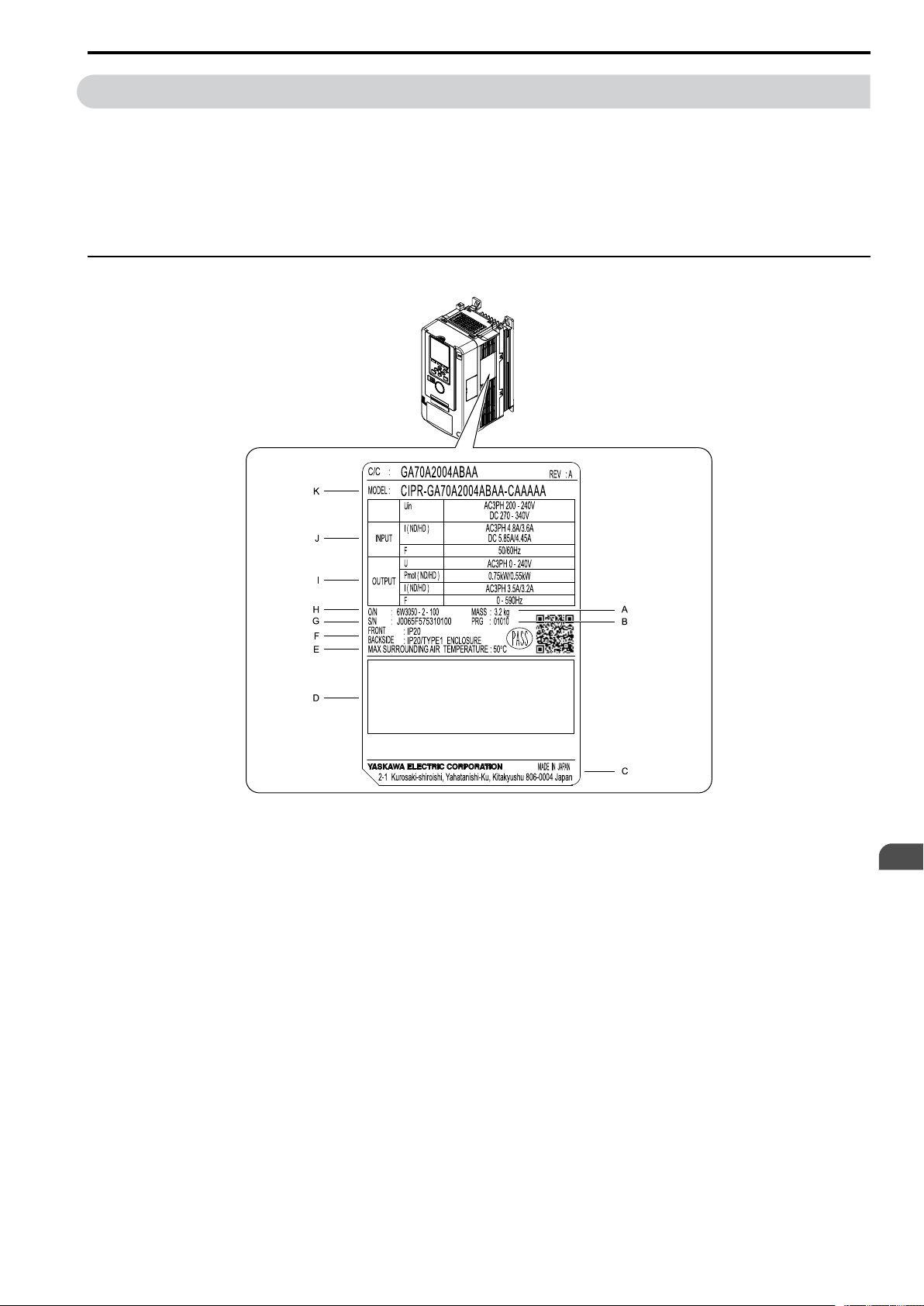
• Verify the drive model number in the "MODEL" section of the drive nameplate to make sure that you received
the correct model.
• Contact your supplier if you receive the incorrect drive model or if the drive does not operate correctly.
◆ Nameplate
A - Mass
B - Drive software version
C - The address of the head office of
Yaskawa Electric Corporation
D - Accreditation standards
E - Surrounding air temperature
F - Protection design
Figure 5.1 Nameplate Information Example
YASKAWA ELECTRIC TOEP C710617 17D YASKAWA AC Drive GA700 Initial Steps EN 5
G - Serial number
H - Lot number
I - Output specifications
J - Input specifications
K - Drive model
EN
Page 6
6 Keypad
6 Keypad
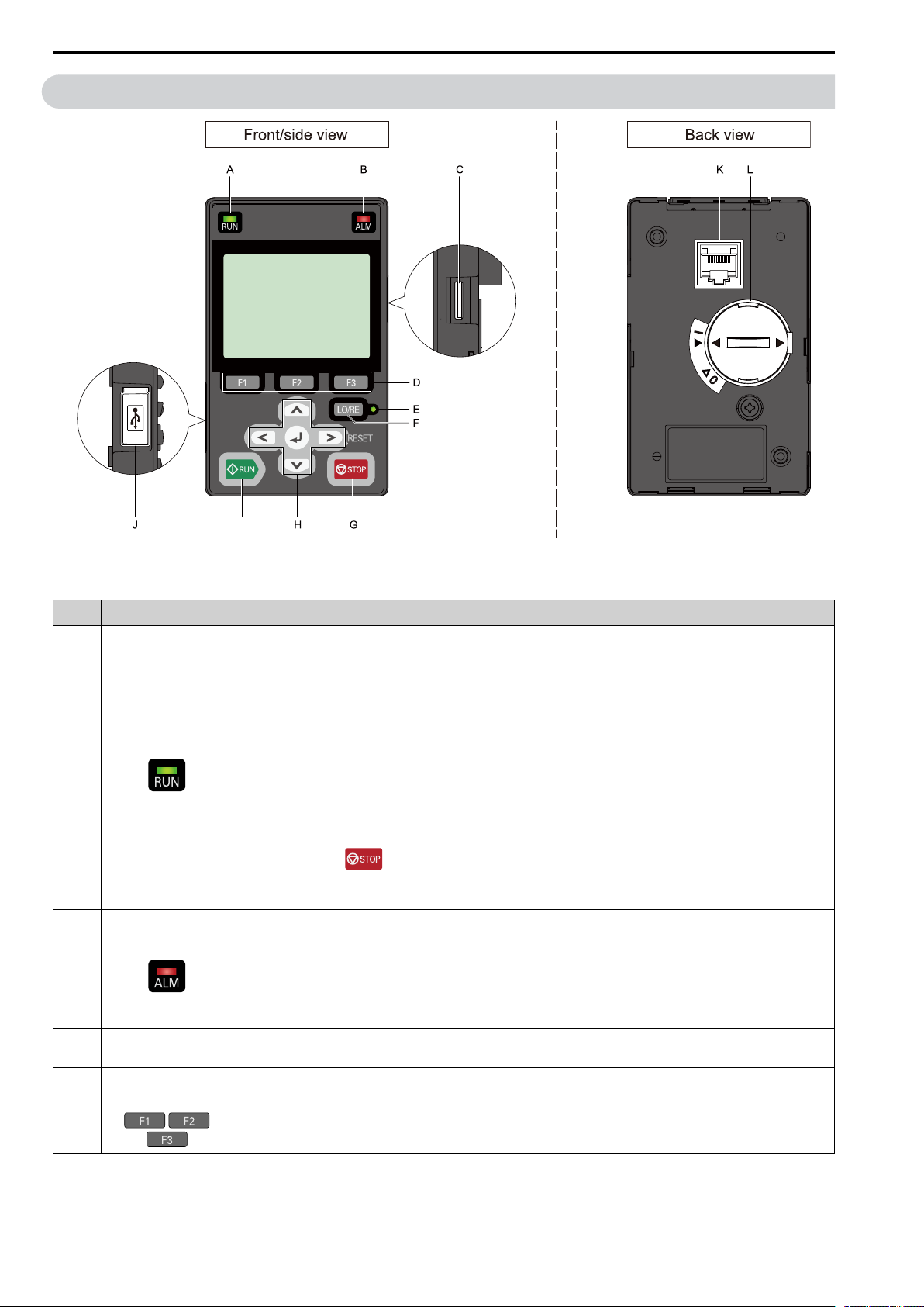
Figure 6.1 Keypad
Table 6.1 Keypad: Names and Functions
No. Name Functions
Illuminates to show that the drive is operating the motor.
The LED turns OFF when the drive stops.
Flashes to show that:
• The drive is decelerating to stop.
• The drive received a Run command with a frequency reference of 0 Hz, but the drive is not set for zero
speed control.
RUN LED
A
ALM LED
B
C
D
microSD Card
Insertion Slot
Function Keys
F1, F2, F3
Flashes quickly to show that:
• The drive received a Run command from the MFDI terminals and is switching to REMOTE Mode
while the drive is in LOCAL Mode.
• The drive received a Run command from the MFDI terminals when the drive is not in Drive Mode.
• The drive received a Fast Stop command.
• The safety function shuts off the drive output.
• The user pushed on the keypad while the drive is operating in REMOTE Mode.
• The drive is energized with an active Run command and b1-17 = 0 [Run Command at Power Up =
Disregard Existing RUN Command].
Illuminates when the drive detects a fault.
Flashes when the drive detects:
• An Alarm
• An oPE parameter setting error
• A fault or alarm during Auto-Tuning
The LED turns OFF when no fault or alarm occurs on the drive.
The insertion point for a microSD card.
The menu shown on the keypad sets the functions for function keys.
The name of each function is in the lower half of the display window.
EN 6 YASKAWA ELECTRIC TOEP C710617 17D YASKAWA AC Drive GA700 Initial Steps
Page 7

No. Name Functions
Illuminates to identify when the drive is operating in LOCAL Mode.
The LED turns OFF when the drive is operating in REMOTE Mode.
E
F
G
LO/RE LED
LO/RE Selection Key
STOP Key
Left Arrow Key Moves the cursor to the left.
Note:
• LOCAL Mode: The keypad controls the Run command and frequency reference. Use the keypad to
enter Run/Stop commands and the frequency reference command.
• REMOTE Mode: The control circuit terminal or serial transmission device controls the Run
command and frequency reference. Use the frequency reference source entered in b1-01 [Frequency
Reference Selection 1] and the Run command source selected in b1-02 [Run Command Selection 1].
Switches drive control for the Run command and frequency reference between the keypad (LOCAL) and
an external source (REMOTE).
Note:
• Stop operation in Drive Mode to enable the LO/RE Selection Key. Set o2-01 = 0 [LO/RE Key
Function Selection = Disabled] to disable when switching from REMOTE to LOCAL will
have a negative effect on system performance.
• The drive will not switch between LOCAL and REMOTE when it is receiving a Run command from
an external source.
Stops drive operation.
Note:
Uses a stop-priority circuit. Push to stop the motor even when a Run command is active at
MFDI terminals. Set o2-02 = 0 [STOP Key Function Selection = Disabled] to disable the priority in
.
6 Keypad
Up Arrow Key/Down
Arrow Key
/
H
Right Arrow Key
(RESET)
ENTER Key
I
J
K RJ-45 Connector Connects the keypad directly to the drive.
L Clock Battery Cover Cover for the customer-supplied clock battery.
WARNING
machine area before switching control sources when b1-07 = 1 [LOCAL/REMOTE Run Selection = Accept Existing RUN
Command]. Failure to obey can cause death or serious injury.
RUN Key
USB Terminal Insertion point for a mini USB cable. Use the mini USB cable to connect the drive to a PC.
Sudden Movement Hazard. Remove all persons and objects from the area around the drive, motor, and
• Scrolls up or down to display the next item or the previous item.
• Selects parameter numbers, and increments or decrements setting values.
• Moves the cursor to the right.
• Continues to the next screen.
• Restarts the drive to clear a fault.
• Enters parameter values and settings.
• Selects menu items to move the user between keypad displays.
• Selects each mode, parameter, and set value.
Starts the drive in LOCAL mode.
Starts the operation in Auto-Tuning Mode.
Note:
Push on the keypad to set the drive to LOCAL Mode before using the keypad to operate the
motor.
EN
YASKAWA ELECTRIC TOEP C710617 17D YASKAWA AC Drive GA700 Initial Steps EN 7
Page 8
6 Keypad
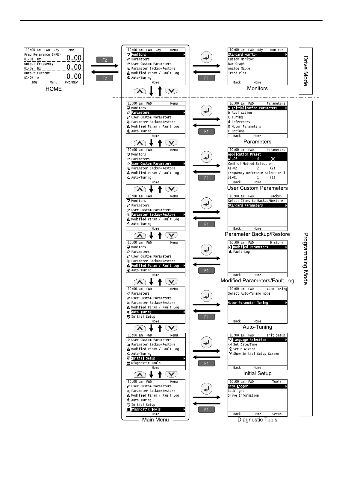
◆ Keypad Mode and Menu Displays
Figure 6.2 Keypad Functions and Display Levels
EN 8 YASKAWA ELECTRIC TOEP C710617 17D YASKAWA AC Drive GA700 Initial Steps
Page 9

6 Keypad
Note:
• Energize the drive with factory defaults to show the Initial Setup screen. Push (Home) to show the HOME screen.
–Select [No] from the [Show Initial Setup Screen] setting to not display the Initial Setup screen.
• Push from the Home screen to show drive monitors.
• Push to set d1-01 [Reference 1] when the Home screen shows U1-01 [Frequency Reference] in LOCAL Mode.
• The keypad will show [Rdy] when the drive is in Drive Mode. The drive is prepared to accept a Run command.
• The drive will not accept a Run command in Programming Mode in the default setting. Set b1-08 [Run Command Select in PRG
Mode] to accept or reject a Run command from an external source while in Programming Mode.
–Set b1-08 = 0 [Disregard RUN while Programming] to reject the Run command from an external source while in Programming Mode
(default).
–Set b1-08 = 1 [Accept RUN while Programming] to accept the Run command from an external source while in Programming Mode.
–Set b1-08 = 2 [Allow Programming Only at Stop] to prevent changes from Drive Mode to Programming Mode while the drive is
operating.
Table 6.2 Drive Mode Screens and Functions
Mode Keypad Screen Function
Drive Mode Monitors Sets monitor items to display.
Parameters Changes parameter settings.
User Custom Parameters Shows the User Parameters.
Parameter Backup/Restore Saves parameters to the keypad as backup.
Programming
Mode
Modified Parameters/Fault Log Shows modified parameters and fault history.
Auto-Tuning Auto-Tunes the drive.
Initial Setup Changes initial settings.
Diagnostic Tools Sets data logs and backlight.
YASKAWA ELECTRIC TOEP C710617 17D YASKAWA AC Drive GA700 Initial Steps EN 9
EN
Page 10

7 LED Status Ring
7 LED Status Ring
The LED Status Ring on the drive cover shows the drive operating status.
A - ALM/ERR
B - Ready
LED Status Description
Illuminated The drive detects a fault.
The drive detects:
• An Alarm
• An oPE parameter setting error
A ALM/ERR
B Ready
C RUN
*1 Refer to Figure 7.1 for the difference between flashing and flashing quickly.
Flashing
Illuminated The drive is operating or is prepared for operation.
Flashing
Flashing Quickly
Illuminated The drive is in regular operation.
Flashing
Flashing Quickly
*1
• A fault or error during Auto-Tuning.
Note:
The LED will illuminate to identify a fault if the drive detects a fault and an alarm at the
same time.
OFF
*1
OFF
*1
OFF The motor is stopped.
No fault or alarm occurs on the drive.
*1
The drive is in STo [Safe Torque OFF] Mode.
The voltage of the main circuit power supply dropped, and only the external 24 V power
supply provides the power to the drive.
• The drive detects a fault.
• There is no fault and the drive received a Run command, but the drive cannot operate (such
as when in Programming Mode, or when is flashing).
• The drive is decelerating to stop.
• The drive received a Run command with a frequency reference of 0 Hz, but the drive is not
*1
set for zero speed control.
• The drive received a DC Injection Braking command.
• The drive received a Run command from the MFDI terminals and is switching to REMOTE
Mode while the drive is in LOCAL Mode.
• The drive received a Run command from the MFDI terminals when the drive is not in
Drive Mode.
• The drive received a Fast Stop command.
• The safety function shuts off the drive output.
• The user pushed on the keypad while the drive is operating in REMOTE Mode.
• The drive is energized with an active Run command and b1-17 = 0 [Run Command at
Power Up = Disregard Existing RUN Command].
• The drive is set to coast-to-stop with timer (b1-03 = 3 [Stopping Method Selection = Coast
to Stop with Timer]), and the Run command is disabled then enabled during the Run wait
time.
C - RUN
EN 10 YASKAWA ELECTRIC TOEP C710617 17D YASKAWA AC Drive GA700 Initial Steps
Page 11

8 Start-Up Procedure
/
Figure 7.1 LED Flashing Statuses
Figure 7.2 Relation between RUN LED and Drive Operation
8 Start-Up Procedure
1. Install and wire the drive.
2. Energize the drive.
3. Use A1-06 [Application Preset] to initialize the drive for a special application if necessary.
4. Run the Setup Wizard to automatically set these functions:
• Control method selection
• Duty rating selection
• Monitor parameters
• Speed reference source
• Run command source
• Acceleration and deceleration times
5. Run the motor without a load.
6. Make sure that the drive is operating correctly and make sure that the host controller is sending commands to
the drive.
7. Connect the load.
8. Run the motor.
9. Make sure that the drive is operating correctly.
10. Fine-tune and set application parameters, such as PID.
11. Check final operation and make sure that parameter settings are correct.
The drive is prepared to run the operation.
EN
YASKAWA ELECTRIC TOEP C710617 17D YASKAWA AC Drive GA700 Initial Steps EN 11
Page 12

9 Mechanical Installation
9 Mechanical Installation
WARNING
near flammable or combustible materials. Attach the drive to metal or other noncombustible material. Failure to obey can cause
death or serious injury.
CAUTION
moving the drive. Failure to obey can cause minor to moderate injury.
Note:
Observe all necessary conditions to safely and correctly install the AC drive. Refer to the Technical Manual for more information.
NOTICE
electrical devices.
Fire Hazard. Do not put flammable or combustible materials on top of the drive and do not install the drive
Crush Hazard. Do not hold the drive by the front cover or terminal cover. Tighten the screws correctly before
Install the drive as specified by EMC Guidelines. Failure to obey can cause incorrect operation and damage to
◆ Installation Position and Distance
Install the drive vertically for sufficient cooling airflow.
Note:
Contact Yaskawa or a Yaskawa representative for more information about installing drive models on their side.
A - Vertical installation B - Horizontal installation
Figure 9.1 Installation Position
■ Single Drive Installation
Use the clearances specified in Figure 9.2 to install the drive. Make sure that there is sufficient space for wiring
and airflow.
A - 50 mm (2 in.) minimum
B - 30 mm (1.2 in.) minimum on both
sides
Figure 9.2 Installation Distances for One Drive
C - 120 mm (4.7 in.) minimum above
and below
D - Airflow direction
■ Install Drives Side-by-Side
Users can install drive models 2004xB to 2082xB and 4002xB to 4044xB side-by-side.
Install the drives as specified by Figure 9.3. Set L8-35 = 1 [Installation Method Selection = Side-by-Side
Mounting].
Derate the output current to align with the ambient temperature.
Install other drive models as specified by Figure 9.2
EN 12 YASKAWA ELECTRIC TOEP C710617 17D YASKAWA AC Drive GA700 Initial Steps
Page 13

9 Mechanical Installation
A - 50 mm (2 in.) minimum
B - 30 mm (1.2 in.) minimum on both
sides
Figure 9.3 Installation Distances for Multiple Drives (Side-by-Side)
Note:
• Align the tops of drives that have different dimensions to help when replacing cooling fans.
• Remove the top protective covers of all drives when mounting UL Type 1 enclosure drives side-by-side.
C - 2 mm (0.08 in.) minimum between
each drive
D - 120 mm (4.7 in.) minimum above
and below
Figure 9.4 Enclosed Wall-Mounted Type (UL Type 1) Installed Side-by-Side
◆ Installation Environment
The installation environment is crucial to ensure proper performance and the expected lifespan of the product.
Ensure the installation environment satisfies the following specifications.
Environment Conditions
Area of Use Indoors
Power supply Overvoltage Category III
Open chassis type (IP20): -10°C to +50 °C (14 °F to 122 °F)
Enclosed wall-mounted type (UL Type 1): -10 °C to +40 °C (14 °F to 104 °F)
• Drive reliability improves in environments without wide temperature fluctuations.
Ambient Temperature
Setting
YASKAWA ELECTRIC TOEP C710617 17D YASKAWA AC Drive GA700 Initial Steps EN 13
• When using the drive in an control panel, install a cooling fan or air conditioner in the area to ensure that the air
temperature inside the enclosure does not exceed the specified levels.
• Do not allow ice to develop on the drive.
• Derate the output current and output voltage to install the drive in areas with ambient temperatures up to 60 °C
(140 °F).
EN
Page 14

9 Mechanical Installation
Environment Conditions
Humidity
Storage Temperature -20 °C to +70 °C (-4 °F to +158 °F) (short-term temperature during transportation)
Surrounding Area
Altitude
Shock
Installation
Orientation
95 RH% or less
Do not allow condensation to develop on the drive.
Pollution degree 2 or less
Install the drive in an area free from:
• oil mist and dust
• metal powder, oil, water, or other foreign materials
• radioactive materials or flammable materials (e.x., wood)
• Harmful gases and liquids
• Low salinity
• Chlorides
Keep wood or other flammable materials away from the drive.
1000 m (3281 ft) maximum
Note:
Derate the output current by 1% for every 100 m (328 ft.) to install the drive in altitudes between 1000 m to
3000 m (3281 ft. to 9843 ft.).
Rated voltage derating is not required:
• when installing the drive at 2000 m (6562 ft.) or lower
• if the drive is grounded with the neutral network when installing the drive at an altitude between 2000 m to
3000 m (6562 ft. to 9843 ft.)
Contact Yaskawa or your nearest sales representative when the drive is not grounded with the neutral network.
• 10 Hz to 20 Hz: 1 G (9.8 m/s
• 20 Hz to 55 Hz:
2004 to 2211, 4002 to 4168: 0.6 G (5.9 m/s
2257 to 2415, 4208 to 4675: 0.2 G (2.0 m/s
Install the drive upright to allow for proper cooling.
2
, 32.15 ft/s2)
2
, 19.36 ft/s2)
2
, 6.56 ft/s2)
NOTICE
electrical interference if components must be near the drive. Failure to obey can cause incorrect operation.
NOTICE
installation and project construction. Put a temporary cover over the top of the drive during installation. Remove the temporary
cover before start-up or the drive will overheat. Failure to obey can cause damage to the drive.
Do not put drive peripheral devices, transformers, or other electronics near the drive. Shield the drive from
Do not let unwanted objects, for example metal shavings or wire clippings, fall into the drive during drive
◆ Removing the Covers
Remove the covers according to the following procedure before wiring the drive.
DANGER
servicing, disconnect all power to the equipment and wait for the time specified on the warning label at a minimum. The internal
capacitor stays charged after the drive is de-energized. The charge indicator LED extinguishes when the DC bus voltage
decreases below 50 Vdc. To prevent electric shock, always wait for at least the amount of time indicated on the warning labels.
When all indicators are OFF, remove the covers before measuring for dangerous voltages to make sure that the drive is safe.
Failure to obey will cause death or serious injury.
DANGER
then remove the covers. Failure to obey could cause death or serious injury.
Electrical Shock Hazard. Do not examine, connect, or disconnect wiring on an energized drive. Before
Electrical shock Hazard. Disconnect the power to the drive and wait for the charge indicator LED to go off,
■ Remove the Front Cover
1. Push the hook on the top part of the keypad and pull forward to remove the keypad.
2. Remove the keypad connector and put it into the connector holder in the direction of the hook on the front
cover.
3. Loosen the front cover screws.
Note:
The number of mounting screws are different for different drive models.
4. Unlock the tabs found on the sides of the front cover.
EN 14 YASKAWA ELECTRIC TOEP C710617 17D YASKAWA AC Drive GA700 Initial Steps
Page 15

5. Carefully pull forward to remove the front cover.
9 Mechanical Installation
A - Keypad connector
B - Hook
Figure 9.5 Remove the Front Cover
C - Connector holder
6. Remove the wiring cover before wiring the main circuit terminal.
A - Wiring cover
■ Remove the Terminal Cover
1. Loosen the screws on the terminal cover.
2. Pull down on the cover.
3. Pull forward on the terminal cover to free it from the drive.
EN
Figure 9.6 Removing the Terminal Cover
YASKAWA ELECTRIC TOEP C710617 17D YASKAWA AC Drive GA700 Initial Steps EN 15
Page 16

9 Mechanical Installation
4. Remove the terminal wiring covers for wiring the main circuit terminals.
◆ Reattaching the Covers
Wire the drive, then reattach the covers before operating the drive.
■ Reattach the Front Cover
1. Reattach the wiring cover.
2. Reattach the front cover to the drive with the supplied screws.
3. Remove the keypad connector from the connector holder on the front cover.
4. Put the keypad connector into the connector on the drive in the direction of the hook.
5. Put the bottom part of the keypad into the drive first, then push the top part of the keypad into the drive to
reattach the keypad.
EN 16 YASKAWA ELECTRIC TOEP C710617 17D YASKAWA AC Drive GA700 Initial Steps
Page 17

9 Mechanical Installation
■ Reattach the Terminal Cover
1. Reattach the wiring cover.
Note:
• The shape of the wiring cover differs depending on the drive model.
• Detach the cutaway section of the wiring cover by clipping only the areas that apply to the wired terminal. If areas that do
not apply to the wired terminal are clipped, the protective enclosure will not maintain the IP20 protective level.
• Hold the cutaway section of the wiring cover firmly to prevent scattering when clipping this section. There is a risk of injury
from scattering of the cutaway section.
• Process the cross section to prevent the cutaway section of the wiring cover from damaging the electric wires.
• If electrical wires other than those specified by Yaskawa are used, the protective enclosure may not maintain the IP20
protective level, even if the wiring cover is used correctly. Contact Yaskawa or your nearest sales representative for details.
2. Reattach the terminal cover to the drive using the supplied screws.
YASKAWA ELECTRIC TOEP C710617 17D YASKAWA AC Drive GA700 Initial Steps EN 17
EN
Page 18

10 Electrical Installation
10 Electrical Installation
DANGER
servicing, disconnect all power to the equipment and wait for the time specified on the warning label at a minimum. The internal
capacitor stays charged after the drive is de-energized. The charge indicator LED extinguishes when the DC bus voltage
decreases below 50 Vdc. When all indicators are OFF, remove the covers before measuring for dangerous voltages to make
sure that the drive is safe. Failure to obey will cause death or serious injury.
DANGER
before energizing the drive. Use terminals for their intended function only. Incorrect wiring or ground connections, and incorrect
repair of protective covers can cause death or serious injury.
WARNING
can cause death or serious injury.
WARNING
Manual for more information about I/O terminals. Incorrect wiring, incorrect grounding, and unsatisfactory repair of the
protective cover could cause death or serious injury and damage to the drive.
Electrical Shock Hazard. Do not examine, connect, or disconnect wiring on an energized drive. Before
Electrical Shock Hazard. Make sure that all electrical connections are correct and install all drive covers
Electrical Shock Hazard. Correctly ground the drive before turning on the EMC filter switch. Failure to obey
Electrical Shock Hazard. Use the drive terminals only for their intended function. Refer to the drive Technical
◆ Standard Connection Diagram
Wire the drive as specified by Figure 10.1. Users can run the motor only with the main circuit wiring when
operating the drive using the keypad.
WARNING
wiring. Incorrect Run/Stop circuit sequence settings can cause death or serious injury from moving equipment.
WARNING
Momentarily closing a digital input terminal can start a drive that is programmed for 3-Wire control. Failure to obey can cause
death or serious injury from moving equipment.
WARNING
When using a 3-Wire sequence:
• Set the drive for 3-Wire sequence.
• Set b1-17 = 0 [Run Command at Power Up = Disregard Existing RUN Command]
• Wire the drive for 3-Wire sequence.
The motor can rotate in reverse when energizing the drive if these three conditions are true:
• The drive is wired for 3-Wire sequence.
• The drive is set for a 2-Wire sequence (default).
• b1-17 = 1 [Accept Existing RUN Command]
Failure to obey can cause death or serious injury from moving equipment.
WARNING
sequence for the drive. Executing the Application Preset function (setting A1-06 to a value other than 0) changes the I/O
terminal function for the drive and may trigger unexpected operation in equipment. Failure to obey can cause death or serious
injury.
NOTICE
manual. The drive is suited for circuits that supply not more than 100,000 RMS symmetrical amperes, 240 Vac maximum (200 V
Class), 480 Vac maximum (400 V Class). Failure to obey can cause death or serious injury.
NOTICE
a drive duty motor or carefully monitor the motor insulation voltage. Failure to obey can cause damage to the motor insulation.
NOTICE
control circuit operation.
Sudden Movement Hazard. Set the multi-function input terminal parameters before closing the control circuit
Sudden Movement Hazard. Correctly wire the start/stop and safety circuits before energizing the drive.
Sudden Movement Hazard.
Sudden Movement Hazard. Execute the Application Preset function after checking I/O signal and the external
Fire Hazard. Install sufficient branch circuit short circuit protection as specified by applicable codes and this
When the input voltage is 440 V or higher or if the wiring distance is longer than 100 m (328 ft.) be sure to use
Do not connect the AC control circuit ground to the drive enclosure. Failure to obey can cause incorrect
EN 18 YASKAWA ELECTRIC TOEP C710617 17D YASKAWA AC Drive GA700 Initial Steps
Page 19

10 Electrical Installation
Figure 10.1 Standard Drive Connection Diagram
*1 Set the wiring sequence to de-energize the drive with the fault relay output. Set L5-02 = 1 [Fault Contact at
Restart Select = Always Active] to de-energize the drive when the drive outputs a fault during fault restart
when using the fault restart function. Be careful when using a cut-off sequence. The default setting for L5-02
is 0 [Active Only when Not Restarting].
*2 Connect peripheral options to terminals -, +1, +2, B1, and B2.
YASKAWA ELECTRIC TOEP C710617 17D YASKAWA AC Drive GA700 Initial Steps EN 19
EN
Page 20

10 Electrical Installation
NOTICE
damage to the drive and peripheral devices.
Do not connect an AC power supply to terminals -, +1, +2, B1, and B2. Failure to obey can cause
*3 Remove the jumper between terminals +1 and +2 when installing a DC reactor.
*4 Models 2110 to 2415 and 4060 to 4675 have a DC reactor.
*5 Set L8-55 = 0 [Internal DB TransistorProtection = Disable] to disable the protection function of the drive
braking transistor when using an optional regenerative converter, regenerative unit, or braking unit. Keeping
L8-55 = 1 [Protection Enabled] can cause rF [Braking Resistor Fault].
*6 Set L3-04 = 0 [Stall Prevention during Decel = Disabled] when using a regenerative converter, regenerative
unit, braking unit, braking resistor, or braking resistor unit. The drive could possibly not stop within the
specified deceleration time when L3-04 = 1 [General Purpose].
*7 Set L8-01 = 1 [3% ERF DB Resistor Protection = Enabled] and set a sequence to de-energize the drive with
the fault relay output when using an ERF-type braking resistor.
*8 Self-cooling motors do not need cooling fan wiring.
*9 Connect 24 V power to terminal PS-AC while the power to the drive control circuit is ON and only the main
circuit is OFF.
*10 Encoder circuit wiring (wiring to PG-B3 option card) is not necessary for applications that do not use motor
speed feedback.
*11 Use a wire jumper between terminals SC and SP or SC and SN to set the MFDI power supply to SINK
Mode, SOURCE Mode, or External power supply.
NOTICE
Do not short circuit terminals SP and SN. Failure to obey will cause damage to the drive.
• SINK Mode: Install a jumper between terminals SC and SP.
Do not short circuit terminals SC and SN. Failure to obey will cause damage to the drive.
• SOURCE Mode: Install a jumper between terminals SC and SN.
Do not short circuit terminals SC and SP. Failure to obey will cause damage to the drive.
• External power supply: No jumper necessary between terminals SC and SN or terminals SC and SP.
*12 The maximum output current capacity for terminals +V and -V on the control circuit is 20 mA.
NOTICE
drive.
Do not install a jumper between terminals +V, -V, and AC. Failure to obey can cause damage to the
*13 DIP switches S1-1 to S1-3 set terminals A1 to A3 for voltage or current input. The default setting for S1-1
and S1-3 is voltage input (“V” side). The default setting for S1-2 is current input (“I” side).
*14 DIP switch S4 sets terminal A3 for analog or PTC input. Set DIP switch S1-3 to the “V” side, and set H3-05
= 0 [Terminal A3 Signal Level Select = 0 to 10V (Lower Limit at 0)] to set terminal A3 for PTC input with
DIP switch S4.
*15 Do not ground the control circuit terminals AC or connect them to the drive. Failure to comply may cause
malfunction or failure.
*16 Connect the positive lead from an external 24 Vdc power supply to terminal PS and the negative lead to
terminal AC. Reversing polarity can cause damage to the drive.
NOTICE
Do not connect reverse terminals PS and AC. Failure to obey will cause damage to the drive.
*17 Use multi-function analog monitor outputs with analog frequency meters, ammeters, voltmeters, and
wattmeters. Do not use monitor outputs with feedback-type signal devices.
*18 Jumper switch S5 sets terminal FM and AM for voltage or current output. The default setting for S5 is
voltage output (“V” side).
*19 Set DIP switch S2 to “ON” to enable the termination resistor in the last drive in a MEMOBUS/Modbus
network.
*20 Use only SOURCE Mode for Safe Disable input.
*21 Disconnect the wire jumpers between terminals H1 and HC and terminals H2 and HC to use the Safe Disable
input.
◆ Wire Gauge and Torque Specifications
Be sure to select the correct wires for the main circuit wiring.
Refer to the Technical Manual for main circuit wire gauges and tightening torques as specified by European
standards and UL standards.
■ Control Circuit Wire Gauges and Tightening Torques
Refer to Table 10.1 and Table 10.2 to select the correct wires and crimp ferrules. Use shielded wire for control
circuit terminal wiring. Use crimp ferrules on the wire ends for more reliable wiring.
EN 20 YASKAWA ELECTRIC TOEP C710617 17D YASKAWA AC Drive GA700 Initial Steps
Page 21

10 Electrical Installation
Table 10.1 Wire Gauges
Bare Wire Crimp Ferrule
Terminal
S1-S8, SC, SN, SP
H1, H2, HC
RP, +V, -V, A1, A2, A3, AC
MP, FM, AM, AC
D+, D-, AC
MA, MB, MC, M1-M6
PS, E(G)
Recommended
Gauge
mm2(AWG)
0.75
(18)
Applicable Gauge
2
mm
(AWG)
• Stranded wire
0.2 to 1.0
(24 to 18)
• Solid wire
0.2 to 1.5
(24 to 16)
Recommended
Gauge
2
(AWG)
mm
0.5
(20)
Applicable Gauge
2
mm
(AWG)
0.25 to 0.5
(24 to 20)
Crimp Ferrules
Attach an insulated sleeve to the wire when connecting crimp ferrules. Refer to Table 10.2 for the recommended
external dimensions and model numbers of the crimp ferrules.
Yaskawa recommends the CRIMPFOX 6 crimping tool from PHOENIX CONTACT.
Figure 10.2 Crimp Ferrule Dimensons
Table 10.2 Crimp Ferrule Models and Dimensions
Wire Gauge
2
mm
(AWG)
0.25 (24) AI 0.25-8YE 12.5 8 0.8 2.0
0.34 (22) AI 0.34-8TQ 12.5 8 0.8 2.0
0.5 (20) AI 0.5-8WH,
Model L (mm) L1 (mm) d1 (mm) d2 (mm)
14 8 1.1 2.5
AI 0.5-8OG
■ Line Voltage Drop
WARNING
than 3.5 mA. The IEC/EN 61800-5-1: 2007 standard specifies that users must wire the power supply to automatically turn off
when the protective ground wire disconnects. Users can also connect a protective ground wire that has a minimum crosssectional area of 10 mm
injury.
Be sure to think about line voltage drop before selecting wire gauges.
Select wire gauges that drop the voltage by 2% or less of the rated voltage. Increase the wire gauge and the cable
length when the risk of voltage drops increases.
Calculate line voltage drop with this formula:
Line voltage drop (V) = × wire resistance (Ω/km) × wiring distance (m) × motor rated current (A) × 10
Electrical Shock Hazard. The leakage current of drive models 4389A to 4675A, 2xxxB/C and 4xxxB/C is more
2
(copper wire) or 16 mm2(aluminum wire). Failure to obey these standards can cause death or serious
-3
■ Dynamic Braking Precautions
EN
Connect braking units to drives with these conditions:
• Models with built-in braking transistors use terminals B1 and -
• Models without built-in braking transistors use terminals +3 and -.
NOTICE
tightening torque information before connecting a dynamic braking option to the drive. Failure to obey can cause damage to the
drive and braking circuit.
Review the Braking Unit and Braking Resistor Unit Installation Manual TOBPC72060001 for wire gauge and
Connect a regenerative converter or regenerative unit with terminals +1 and -.
NOTICE
YASKAWA ELECTRIC TOEP C710617 17D YASKAWA AC Drive GA700 Initial Steps EN 21
Do not connect a braking resistor to terminals +1 or -. Failure to obey can cause damage to the drive circuitry.
Page 22

11 Drive Start-Up
◆ Wiring the Main Circuit and Motor
Refer to Figure 10.3 for a view of the drive with line and load wiring.
WARNING
B2 to the ground terminal. Failure to obey can cause death, serious injury, or damage to equipment.
Electrical Shock Hazard. Do not connect terminals R/L1, S/L2, T/L3, U/T1, V/T2, W/T3, -, +1, +2, +3, B1, or
A - Terminal block (TB2-3)
B - Terminal block (TB2-2)
C - Terminal block (TB2-1)
D - DC bus voltage terminals
(configuration changes by drive
model)
E - Drive ground terminals
F - Motor case ground
Figure 10.3 Wiring the Line and Load
G - Three-phase motor
H - Three-phase power supply
I - Fuses and RCD
J - Terminal block (TB1)
K - Terminal block (TB3)
L - Terminal block (TB4)
11 Drive Start-Up
◆ Setup Wizard
Refer to the motor nameplate to record the information in the following table before starting the drive.
Item Value
Motor Rated Power kW
Motor Rated Voltage V
Motor Rated Current A
Motor Rated Frequency Hz
EN 22 YASKAWA ELECTRIC TOEP C710617 17D YASKAWA AC Drive GA700 Initial Steps
Page 23

11 Drive Start-Up
Item Value
Motor Maximum Output Frequency Hz
Number of Motor Poles
Motor Base Rotation Speed min
Number of Motor Encoder Pulses ppr
-1
(r/min)
The drive setup wizard prepares the drive for operation. Use the information from the table for Auto-Tuning and
test runs.
1. Energize the drive to show the initial setup screen.
Note:
If the keypad does not show the Initial Setup screen, push [Menu] to show the Menu screen then push to
select [Initial Setup].
2. Select [Set Date/Time] to set the date and time.
Note:
Open the clock battery cover to put in a battery to use the clock functions. Use a Hitachi Maxell CR2016 manganese dioxide
lithium battery or an equivalent battery with the these properties:
• Nominal voltage: 3 V
• Operating temperature range: -20°C to +85°C (-4°F to +185°F)
• Nominal battery life: 2 years (20 °C (68 °F) ambient temperature)
3. Select [Setup Wizard] and follow the instructions shown on the keypad until the setup wizard completes.
The drive and motor are prepared for operation.
◆ Auto-Tuning
WARNING
of the rated frequency of the motor. Make sure that there are no issues related to safety in the surrounding area. Failure to obey
can cause death or serious injury and damage to machinery.
WARNING
Failure to comply could cause death or serious injury and damage machinery.
Auto-Tuning automatically sets parameters on the drive connected to the motor. Some parameters need to be input
individually when Auto-Tuning.
1. Select [Auto-Tuning] then select the Auto-Tuning Mode.
2. Use the information in Table 11.1 and Table 11.2 to select T1-01 [Auto-Tuning Mode Selection] and T4-01
[EZ Tuning Mode Selection].
3. Push to start Auto-Tuning.
Refer to the Technical Manual for more information about Auto-Tuning.
Crush Hazard. When performing Rotational Auto-Tuning, the motor rotates at a frequency that is 50% or more
Sudden Movement Hazard. Disconnect the load from the motor when performing Rotational Auto-Tuning.
EN
YASKAWA ELECTRIC TOEP C710617 17D YASKAWA AC Drive GA700 Initial Steps EN 23
Page 24

11 Drive Start-Up
Table 11.1 Auto-Tuning Mode Selection
Mode T1-01 Application Conditions and Benefits
Recommended tuning mode for the most accurate results. Select this tuning mode
Rotational AutoTuning
Stationary AutoTuning 1
Stationary LineLine Resistance
Mode T4-01 Application Conditions and Benefits
Motor Parameter
Setting
Line-to-Line
Resistance
when:
0
• Users can decouple the motor from the load.
• Users cannot decouple the motor from the load, but the motor load is less than
30%.
Automatically calculates motor parameters for vector control. Select this tuning
mode when:
1
• Users cannot decouple the motor from the load.
• The motor test report data is not available.
Select this tuning mode when:
• The drive and motor capacities are different.
2
• The drive is in V/f Control.
• Replacing the drive and motor.
Table 11.2 EZ Tuning Mode Selection
Sets motor parameters.
0
Select this tuning mode after replacing the drive, motor, and motor cables.
1
A1-02 [Control
Method
Selection]
0
[V/f]2[OLV]
- YES
- YES
YES YES
A1-02 = 8
[EZOLV]
YES
YES
◆ Change Parameter Settings
The procedure below shows how to change the C1-01 [Acceleration Time 1] setting. Use this procedure to set
parameters for other applications
1. Push (Home) to show the HOME screen.
Note:
• The keypad will show [Home] in the top right corner when the HOME screen is active.
• If [Home] is not on , push (Back).
2. Push (Menu).
3. Push or to select [Parameters], then push .
EN 24 YASKAWA ELECTRIC TOEP C710617 17D YASKAWA AC Drive GA700 Initial Steps
Page 25

12 Drive Control, Duty Modes, and Programming
4. Push or to select [C Tuning], then push .
5. Push or to select [C1 Accel & Decel Time], then push .
6. Push or to select C1-01, then push .
7. Push or to select the specified digit, then push or to select the correct number.
• Push [Default] to set the parameters to the factory default.
• Push [Min/Max] to move between the minimum value and maximum value.
8. Push to keep the changes.
9. Continue to set parameters or push [Back] to go back to the HOME screen.
12 Drive Control, Duty Modes, and Programming
EN
◆ Drive Control Methods
This section gives information about these basic motor control methods:
• V/f Control (V/f)
• Open Loop Vector control (OLV)
• EZ Vector Control for induction motors only (EZOLV)
Refer to the Technical Manual for information about speed feedback and Permanent Magnet/Synchronous
Reluctance motor control methods.
Use parameter A1-02 [Control Method Selection] to set the correct motor control method for the application.
YASKAWA ELECTRIC TOEP C710617 17D YASKAWA AC Drive GA700 Initial Steps EN 25
Page 26

12 Drive Control, Duty Modes, and Programming
Control Method A1-02 Setting Main Applications
• General variable-speed
• Operating more than one motor from one drive
• When replacing the motor without motor parameter values.
• General variable-speed
• High precision and speed control without speed feedback
• General variable-speed
• No high precision, no speed control, and no speed feedback
V/f
OLV 2
EZOLV 8
(default)
0
◆ Drive Duty Modes
The drive has two duty modes from which to select for the application: Heavy Duty (HD) and Normal Duty (ND).
The duty rating switches to HD2 or ND2 when E1-01 [Input AC Supply Voltage] ≥ 460 V. These specifications are
different between HD1/HD2 and ND1/ND2:
• The input power kVA
• The maximum applicable motor output
• The rated input current
• The rated output capacity
• The rated output current
Refer to Table 12.1 for information about the differences between HD and ND ratings.
Table 12.1 Drive Duty Modes
Duty Rating
Heavy Duty Rating 1
(HD1)
Heavy Duty Rating 2
(HD2)
Normal Duty Rating
1
(ND1)
Normal Duty Rating
2
(ND2)
E1-01 Setting
Input Voltage
• ≥ 200 V and < 240 V
• ≥ 380 V and < 460 V
≥ 460 V and < 480 V
• ≥ 200 V and < 240 V
• ≥ 380 V and < 460 V
≥ 460 V and < 480 V
C6-01
Setting
0
1
Application
• Extruder
• Conveyor
• Constant torque or high
overload capacity
• Fan
• Pump
• Blower
• Variable speed control
◆ Drive Parameters
Refer to the following table when setting the most important parameters.
Note:
Users can change parameters with “RUN” in the “No.” column during Run.
No.
(Hex.)
A1-00
(0100)
RUN
A1-02
(0102)
A1-03
(0103)
b1-01
(0180)
Language Selection Sets the language for the LCD keypad.
Control Method Selection Sets the control method for the drive application and the motor.
Initialize Parameters Sets parameters to default values.
Frequency Reference
Selection 1
Name Description
0: English, 1: Japanese, 2: German, 3: French, 4: Italian, 5: Spanish, 6: Portuguese,
7: Chinese, 8: Czech, 9: Russian, 10: Turkish, 11: Polish, 12: Greek
0: V/f Control, 1: V/f Control w/ PG, 2: Open Loop Vector, 3: Closed Loop Vector,
4: Advanced Open Loop Vector, 5: PM Open Loop Vector,
6: PM Advanced Open Loop Vector, 7: PM Closed Loop Vector, 8: EZ Vector Control
0: No Initialization, 1110: User Initialization, 2220: 2-Wire Initialization,
3330: 3-Wire Initialization
Sets the input method for the frequency reference.
0: Keypad, 1: Analog Input, 2: Memobus/Modbus Communications, 3: Option PCB,
4: Pulse Train Input
Default Carrier
Frequency
2 kHz
2 kHz Swing-PWM
Overload Tolerance
(oL2 [Drive
Overload])
150% rated output
current for 60 s
110% rated output
current for 60 s
EN 26 YASKAWA ELECTRIC TOEP C710617 17D YASKAWA AC Drive GA700 Initial Steps
Page 27

12 Drive Control, Duty Modes, and Programming
No.
(Hex.)
b1-02
(0181)
b1-03
(0182)
b1-04
(0183)
C1-01
(0200)
RUN
C1-02
(0201)
RUN
C2-01
(020B)
C2-02
(020C)
C2-03
(020D)
C2-04
(020E)
C6-01
(0223)
C6-02
(0224)
d1-01 to d1-16
(0280 - 0291)
RUN
d1-17
(0292)
RUN
d2-01
(0289)
d2-02
(028A)
E1-01
(0300)
E1-04
(0303)
E1-05
(0304)
E1-06
(0305)
E1-09
(0308)
E2-01
(030E)
Name Description
Run Command Selection1Sets the input method for the Run command.
0: Keypad, 1: Analog Input, 2: Memobus/Modbus Communications, 3: Option PCB
Stopping Method
Selection
Reverse Operation
Selection
Acceleration Time 1 Sets the length of time to accelerate from zero to maximum output frequency.
Deceleration Time 1 Sets the length of time to decelerate from maximum output frequency to zero.
S-Curve Time @ Start of
Accel
S-Curve Time @ End of
Accel
S-Curve Time @ Start of
Decel
S-Curve Time @ End of
Decel
Normal / Heavy Duty
Selection
Carrier Frequency
Selection
Reference 1 to 16 Sets the frequency reference in the units from o1-03 [Frequency Display Unit Selection].
Jog Reference Sets the Jog frequency reference in the units from o1-03 [Frequency Display Unit
Frequency Reference
Upper Limit
Frequency Reference
Lower Limit
Input AC Supply Voltage Sets the drive input voltage. Set this parameter to the nominal voltage of the AC power
Maximum Output
Frequency
Maximum Output Voltage Sets the maximum voltage for the V/f pattern.
Base Frequency Sets the base frequency for the V/f pattern.
Minimum Output
Frequency
Motor Rated Current
(FLA)
Sets the method to stop the motor after removing a Run command or entering a Stop
command.
0: Ramp to Stop, 1: Coast to Stop, 2: DC Injection Braking to Stop,
3: Coast to Stop with Timer, 9: Stop with Constant Distance
Enables and disables reverse operation. Disable reverse operation in fan or pump
applications where reverse rotation is dangerous.
0: Reverse Enabled, 1: Reverse Disabled
Sets the time to start S-curve acceleration.
Sets the time to complete S-curve acceleration.
Sets the time to start S-curve deceleration.
Sets the time to complete S-curve deceleration.
Sets the duty rating of the drive.
0: Heavy Duty Rating, 1: Normal Duty Rating
Sets the carrier frequency for the transistors in the drive.
1: 2.0 kHz, 2: 5.0 kHz (4.0 kHz for AOLV/PM), 3: 8.0 kHz (6.0 kHz for AOLV/PM),
4: 10.0 kHz (8.0 kHz for AOLV/PM), 5: 12.5 kHz (10.0 kHz for AOLV/PM),
6: 15.0 kHz (12.0 kHz AOLV/PM), 7: Swing PWM 1 (Audible Sound 1),
8: Swing PWM 2 (Audible Sound 2), 9: Swing PWM 3 (Audible Sound 3),
A: Swing PWM 4 (Audible Sound 4), F: User Defined (C6-03 to C6-05)
Selection]. Set H1-xx = 6 [MFDI Function Select = Jog Reference Selection] to use the Jog
frequency reference.
Sets maximum limit for all frequency references. This value is a percentage of E1-04
[Maximum Output Frequency].
Sets minimum limit for all frequency references. This value is a percentage of E1-04
[Maximum Output Frequency].
supply.
Sets the maximum output frequency for the V/f pattern.
Sets the minimum output frequency for the V/f pattern.
Sets the motor rated current in amperes.
EN
YASKAWA ELECTRIC TOEP C710617 17D YASKAWA AC Drive GA700 Initial Steps EN 27
Page 28

12 Drive Control, Duty Modes, and Programming
No.
(Hex.)
E2-11
(0318)
H1-01 to H1-08
(0438, 0439,
0400 - 0405)
H2-01
(040B)
H2-02
(040C)
H3-01
(0410)
H3-02
(0434)
H3-03
(0411)
RUN
H3-04
(0412)
RUN
H3-05
(0413)
H3-06
(0414)
H3-07
(0415)
RUN
H3-08
(0416)
RUN
H3-09
(0417)
H3-10
(0418)
H3-11
(0419)
RUN
H3-12
(041A)
RUN
H3-13
(041B)
H3-14
(041C)
H4-01
(041D)
H4-02
(041E)
RUN
Name Description
Motor Rated Power (kW) Sets the motor rated power in 0.01 kW units. (1 HP = 0.746 kW)
Terminal Sx Function
Selection
Term M1-M2 Function
Selection
Term M3-M4 Function
Selection
Terminal A1 Signal Level
Select
Terminal A1 Function
Selection
Terminal A1 Gain Setting Sets the gain of the analog signal input to MFAI terminal A1.
Terminal A1 Bias Setting Sets the bias of the analog signal input to MFAI terminal A1.
Terminal A3 Signal Level
Select
Terminal A3 Function
Selection
Terminal A3 Gain Setting Sets the gain of the analog signal input to MFAI terminal A3.
Terminal A3 Bias Setting Sets the bias of the analog signal input to MFAI terminal A3.
Terminal A2 Signal Level
Select
Terminal A2 Function
Selection
Terminal A2 Gain Setting Sets the gain of the analog signal input to MFAI terminal A2.
Terminal A2 Bias Setting Sets the bias of the analog signal input to MFAI terminal A2.
Analog Input FilterTime
Constant
Analog Input Terminal
Enable Sel
Terminal FM Analog
Output Select
Terminal FM Analog
Output Gain
Sets the functions for MFDI terminals S1 to S8.
Sets the function for MFDO terminal M1-M2.
Sets the function for MFDO terminal M3-M4.
Sets the input signal level for MFAI terminal A1.
0: 0 to 10V (Lower Limit at 0), 1: -10 to +10V (Bipolar Reference), 2: 4 to 20 mA,
3: 0 to 20 mA
Sets the function for MFAI terminal A1.
Sets the input signal level for MFAI terminal A3.
0: 0 to 10V (Lower Limit at 0), 1: -10 to +10V (Bipolar Reference), 2: 4 to 20 mA,
3: 0 to 20 mA
Sets the function for MFAI terminal A3.
Sets the input signal level for MFAI terminal A2.
0: 0 to 10V (Lower Limit at 0), 1: -10 to +10V (Bipolar Reference), 2: 4 to 20 mA,
3: 0 to 20 mA
Sets the function for MFAI terminal A2.
Sets the time constant for primary delay filters on MFAI terminals.
Sets which Sx terminal is enabled when H1-xx = C [MFDI Function Select = Analog
Terminal Enable Selection] is ON.
1: Terminal A1 only, 2: Terminal A2 only, 3: Terminals A1 and A2, 4: Terminal A3 only,
5: Terminals A1 and A3, 6: Terminals A2 and A3, 7: Terminals A1, A2, and A3
Sets which drive monitor Ux-xx to output from MFAO terminal FM.
Sets the gain of the Ux-xx monitor signal in H4-01 [Terminal FM Analog Output Select].
EN 28 YASKAWA ELECTRIC TOEP C710617 17D YASKAWA AC Drive GA700 Initial Steps
Page 29

13 Faults and Alarms
No.
(Hex.)
H4-03
(041F)
RUN
H4-04
(0420)
H4-05
(0421)
RUN
H4-06
(0422)
RUN
H4-07
(0423)
H4-08
(0424)
L1-01
(0480)
L1-02
(0481)
L3-04
(0492)
Name Description
Terminal FM Analog
Output Bias
Terminal AM Analog
Output Select
Terminal AM Analog
Output Gain
Terminal AM Analog
Output Bias
Terminal FM Signal Level
Select
Terminal AM Signal
Level Select
Motor Overload (oL1)
Protection
Motor Overload
Protection Time
Stall Prevention during
Decel
Sets the bias of the Ux-xx monitor signal in H4-01 [Terminal FM Analog Output Select].
Sets which drive monitor Ux-xx to output from MFAO terminal AM.
Sets the gain of the Ux-xx monitor signal in H4-04 [Terminal AM Analog Output Select].
Sets the bias of the Ux-xx monitor signal in H4-04 [Terminal AM Analog Output Select].
Sets the output signal level from MFAO terminal FM.
0: 0 to 10 Vdc, 1: -10 to +10 Vdc, 2: 4 to 20 mA
Sets the output signal level from MFAO terminal AM.
0: 0 to 10 Vdc, 1: -10 to +10 Vdc, 2: 4 to 20 mA
Sets the motor overload protection function that uses electronic thermal protectors.
0: Disabled, 1: Variable Torque, 2: Constant Torque 10:1 Speed Range,
3: Constant Torque 100:1 SpeedRange, 4: PM Variable Torque, 5: PM Constant Torque,
6: Variable Torque (50Hz)
Sets the motor overload (oL1) protection time. Usually it is not necessary to change this
setting.
Sets the method that the drive will use to prevent overvoltage faults when decelerating.
0: Disabled, 1: General Purpose, 2: Intelligent (Ignore Decel Ramp),
3: General Purpose w/ DB resistor, 4: Overexcitation/High Flux,
5: Overexcitation/High Flux 2
13 Faults and Alarms
Look at the drive keypad for fault and alarm information if the drive or motor do not operate correctly.
For drive alarms:
• Keypad shows the alarm code
• and ALM/ERR on the LED Status Ring flash.
• The drive will continue to operate the motor. Some alarms let the user select a motor stopping method.
For drive faults:
• Keypad shows the fault code
• and ALM/ERR on the LED Status Ring stay illuminated.
• The drive shuts off output, the fault relay output turns ON, and the motor coasts to stop.
◆ Fault Reset Procedure
1. Remove the cause of the fault or alarm.
2. Push (Reset) or on the keypad while the keypad is showing the fault or alarm code.
This table lists the most frequent alarms and faults with possible causes and solutions.
Refer to the Technical Manual for a full list of faults and alarms.
Code Name Causes Possible Solutions
bb Baseblock A digital input set for the software
CrST Remove RUN Command to
Reset
baseblock function is OFF and the drive
will not accept a Run command.
Tried to reset a fault when a Run
command was active.
• Make sure that the digital input function
selections are correct.
• Make sure that the host controller sequence is
correct.
Stop the Run command and reset the drive.
EN
YASKAWA ELECTRIC TOEP C710617 17D YASKAWA AC Drive GA700 Initial Steps EN 29
Page 30

13 Faults and Alarms
EF FWD/REV Run Command
Input Error
EF1 to EF8 External Fault (Terminal
Sx)
GF Ground Fault A current short to ground was more than
oC Overcurrent • There is a short circuit or ground fault
oL1 Motor Overload The motor load is too heavy. Decrease the motor load.
oL2 Drive Overload • The load is too heavy.
ov Overvoltage • The DC bus voltage is too high.
PF Input Phase Loss Drive input power has an open phase. Correct all wiring errors in the main circuit drive
A forward command and a reverse
command were input at the same time
for longer than 500 ms.
One of the digital inputs caused an
external fault through an external
device.
The digital input settings are incorrect.
50% of the rated current on the output
side of the drive.
The motor wiring or insulation are
damaged.
Too much parasitic capacitance at drive
output.
on the drive output side.
• The load is too heavy.
• The accel/decel times are too short.
• The motor data is incorrect.
• The V/f pattern settings are incorrect.
• A magnetic contactor was switched at
the output.
Operating a general-purpose motor
slower than the rated speed with a high
load.
Cycle times are too short during
acceleration and deceleration.
The motor rated current setting is
incorrect.
• The drive capacity is too small.
• Torque is too high at low speed.
• The deceleration time is too short.
• Stall prevention is disabled.
• The braking resistor is missing or
damaged.
• Motor control is not stable.
• The input voltage is too high.
The drive input power terminals are not
tight.
Too much fluctuation in the drive input
power voltage.
Make sure that the sequence is correct. Do not set
the forward and reverse inputs at the same time.
• Find the device that caused the external faults.
Remove the cause and reset the fault.
• Make sure that the digital input terminal
functions are correct.
• Make sure that the output wiring is correct.
• Make sure that the motor does not have short
circuits or damaged insulation.
Replace damaged parts.
Reduce the carrier frequency in C6-02 [Carrier
Frequency Selection].
• Replace damaged output wiring and motor
wiring.
• Repair damaged machine parts.
• Make sure that the drive parameter settings are
correct.
• Make sure that the output contactor sequence is
correct.
Use a motor with external cooling and set the
correct motor type in L1-01 [Motor Overload (oL1)
Protection].
Increase the acceleration and deceleration times.
Make sure that the motor rated current in E2-01
[Motor Rated Current (FLA)] is correct.
• Examine the load.
• Make sure that the drive is sufficiently large for
the load.
• The overload capability of the drive decreases at
low speeds. Decrease the load or replace the
drive with a larger capacity model.
• Increase the deceleration time.
• Set L3-04 [Stall Prevention during Decel] ≠ 0 to
enable stall prevention.
• Replace the braking resistor.
• Make sure that motor parameter settings are
correct and adjust torque and slip compensation
if necessary.
• Make sure that the power supply voltage meets
drive specifications.
input power.
Tighten the terminals to the correct tightening
torque.
• Measure the voltage from the drive input power.
• Make the drive input power stable.
EN 30 YASKAWA ELECTRIC TOEP C710617 17D YASKAWA AC Drive GA700 Initial Steps
Page 31

14 Disposal Instructions
There is unsatisfactory balance between
voltage phases.
The main circuit capacitors are
unserviceable.
STo Safe Torque OFF The two Safe Disable inputs are open.
The drive output is safely disabled and
the motor will not start.
SToF Safe Torque OFF Hardware Opening only one Safe Disable input
disables drive output. (Usually inputs
H1 and H2 must open to disable drive
output.)
• One input is damaged and will not
switch off after removing the external
signal.
• The host controller switched off one
input.
• Make the drive input power stable.
• Disable phase loss detection.
• Make sure that the capacitor maintenance time in
monitor U4-05 [CapacitorMaintenance] is less
than 90%.
• Replace the main capacitors if U4-05 is more
than 90%. Contact Yaskawa or a Yaskawa
representative to replace the main capacitors.
Make sure that there are no problems with the drive
input power. If drive input power is correct and the
alarm continues to occur, replace the control board
or the drive. Contact Yaskawa or a Yaskawa
representative to replace the control board.
• Find the problem causing the host controller
safety device to disable the drive.
• If the Safe Disable function does not disable the
drive or if it is not used for the ISO/EN 13849-1
(PL e (Cat.III)), and IEC/EN 61508 (SIL3),
connect a jumper between terminals HC, H1,
and H2.
• Make sure that the wiring from the host
controller is correct and the controller set the two
signals correctly.
• If the signals are correct and the alarm continues
to occur, replace the drive.
14 Disposal Instructions
Correctly discard the drive, packing material, battery, and microSD card as specified by regional, local, and
municipal laws and regulations for this product. (Example: European Waste 16 02 14)
Note:
• Remove the battery and microSD card from the keypad before discarding the drive.
• The battery is not recyclable. Discard used batteries as specified by the battery manufacturer.
• Customers are responsible for microSD card data protection. PC functions that format and delete the data may not be sufficient to fully
erase the microSD card data.
Yaskawa recommends that customers physically destroy the microSD card in a shredder or use data wipe software to fully erase the
card.
EN
YASKAWA ELECTRIC TOEP C710617 17D YASKAWA AC Drive GA700 Initial Steps EN 31
Page 32

YASKAWA AC Drive GA700
High Performance Type
Initial Steps
YASKAWA EUROPE GmbH
Hauptstraβe 185, 65760 Eschborn, Germany
Phone: +49-6196-569-500
E-mail: support@yaskawa.eu.com
Internet: http://www.yaskawa.eu.com
DRIVE CENTER (INVERTER PLANT)
2-13-1, Nishimiyaichi, Yukuhashi, Fukuoka, 824-8511, Japan
Phone: +81-930-25-2548 Fax: +81-930-25-3431
Internet: http://www.yaskawa.co.jp
YASKAWA AMERICA, INC.
2121, Norman Drive South, Waukegan, IL 60085, U.S.A.
Phone: +1-800-YASKAWA (927-5292) or +1-847-887-7000 Fax: +1-847-887-7310
Internet: http://www.yaskawa.com
*TOEPC71061717*
In the event that the end user of this product is to be the military and said product is to be
employed in any weapons systems or the manufacture thereof, the export will fall under the
relevant regulations as stipulated in the Foreign Exchange and Foreign Trade Regulations.
Therefore, be sure to follow all procedures and submit all relevant documentation according
to any and all rules, regulations and laws that may apply.
Specifications are subject to change without notice for ongoing product modifications and
improvements.
© 2016 YASKAWA Electric Corporation
MANUAL NO. TOEP C710617 17D <3>-0
Published in Japan December 2016
15-11-8_YEU
Original instructions
 Loading...