

Page 1
YASKAWA AC Drive GA500
Installation and Operation Instruction
Type CIPR-GA50Cxxxxxxxx
200 V Class, Three-Phase Input: 0.1 to 22 kW
200 V Class, Single-Phase Input: 0.1 to 4.0 kW
400 V Class, Three-Phase Input: 0.37 to 30 kW
PDF
Page 2

This Page Intentionally Blank
2 YASKAWA TOMPC71061753A YASKAWA AC Drive GA500 Installation and Operation Instruction
Page 3

Table of Contents
1. English . . . . . . . . . . . . . . . . . . . . . . . . . . . . . . . . . . . . . . . . . . . . . . . . . . . . . . . . . .11
General Information . . . . . . . . . . . . . . . . . . . . . . . . . . . . . . . . . . . . . . . . . . . . . . . . . . . . . . . .11
Qualifications for the Intended User . . . . . . . . . . . . . . . . . . . . . . . . . . . . . . . . . . . . . . . . . . .11
Section Safety . . . . . . . . . . . . . . . . . . . . . . . . . . . . . . . . . . . . . . . . . . . . . . . . . . . . . . . . . . . . .11
Explanation of Signal Words . . . . . . . . . . . . . . . . . . . . . . . . . . . . . . . . . . . . . . . . . . . . .11
General Safety Instructions . . . . . . . . . . . . . . . . . . . . . . . . . . . . . . . . . . . . . . . . . . . . . .11
Intended Use. . . . . . . . . . . . . . . . . . . . . . . . . . . . . . . . . . . . . . . . . . . . . . . . . . . . . . . . . 14
Exclusion of Liability . . . . . . . . . . . . . . . . . . . . . . . . . . . . . . . . . . . . . . . . . . . . . . . . . . . 14
Keypad: Names and Functions . . . . . . . . . . . . . . . . . . . . . . . . . . . . . . . . . . . . . . . . . . . . . . 14
Installation . . . . . . . . . . . . . . . . . . . . . . . . . . . . . . . . . . . . . . . . . . . . . . . . . . . . . . . . . . . . . . . 17
Installation Environment. . . . . . . . . . . . . . . . . . . . . . . . . . . . . . . . . . . . . . . . . . . . . . . . 17
Removing/Reattaching Covers . . . . . . . . . . . . . . . . . . . . . . . . . . . . . . . . . . . . . . . . . . 18
Electrical Installation. . . . . . . . . . . . . . . . . . . . . . . . . . . . . . . . . . . . . . . . . . . . . . . . . . . . . . . 18
Standard Connection Diagram . . . . . . . . . . . . . . . . . . . . . . . . . . . . . . . . . . . . . . . . . . 19
Wire Selection. . . . . . . . . . . . . . . . . . . . . . . . . . . . . . . . . . . . . . . . . . . . . . . . . . . . . . . . 21
Control Circuit Wire Gauges and Tightening Torques . . . . . . . . . . . . . . . . . . . . . . . . 21
Drive Start-Up . . . . . . . . . . . . . . . . . . . . . . . . . . . . . . . . . . . . . . . . . . . . . . . . . . . . . . . . . . . . 22
Set up the Drive with General-Purpose Setup Mode . . . . . . . . . . . . . . . . . . . . . . . . . 22
Drive Parameters . . . . . . . . . . . . . . . . . . . . . . . . . . . . . . . . . . . . . . . . . . . . . . . . . . . . . . . . . 23
Troubleshooting . . . . . . . . . . . . . . . . . . . . . . . . . . . . . . . . . . . . . . . . . . . . . . . . . . . . . . . . . . 26
Fault Reset Procedure . . . . . . . . . . . . . . . . . . . . . . . . . . . . . . . . . . . . . . . . . . . . . . . . . 26
Disposal. . . . . . . . . . . . . . . . . . . . . . . . . . . . . . . . . . . . . . . . . . . . . . . . . . . . . . . . . . . . . . . . . 29
Disposal Instructions . . . . . . . . . . . . . . . . . . . . . . . . . . . . . . . . . . . . . . . . . . . . . . . . . . 29
WEEE Directive . . . . . . . . . . . . . . . . . . . . . . . . . . . . . . . . . . . . . . . . . . . . . . . . . . . . . . 29
European Standards . . . . . . . . . . . . . . . . . . . . . . . . . . . . . . . . . . . . . . . . . . . . . . . . . . . . . . 29
CE Low Voltage Directive Compliance . . . . . . . . . . . . . . . . . . . . . . . . . . . . . . . . . . . . 30
Area of Use . . . . . . . . . . . . . . . . . . . . . . . . . . . . . . . . . . . . . . . . . . . . . . . . . . . . . . . . . . 30
Connect a Fuse to the Input Side (Primary Side) . . . . . . . . . . . . . . . . . . . . . . . . . . . . 30
EMC Directive . . . . . . . . . . . . . . . . . . . . . . . . . . . . . . . . . . . . . . . . . . . . . . . . . . . . . . . . 30
Wire Selection. . . . . . . . . . . . . . . . . . . . . . . . . . . . . . . . . . . . . . . . . . . . . . . . . . . . . . . . 30
Install a Drive to Conform to the EMC Directive . . . . . . . . . . . . . . . . . . . . . . . . . . . . . 31
Enable the Internal EMC Filter. . . . . . . . . . . . . . . . . . . . . . . . . . . . . . . . . . . . . . . . . . . 32
Safe Disable Input . . . . . . . . . . . . . . . . . . . . . . . . . . . . . . . . . . . . . . . . . . . . . . . . . . . . . . . . 33
Safe Disable Specifications . . . . . . . . . . . . . . . . . . . . . . . . . . . . . . . . . . . . . . . . . . . . . 33
Safe Disable Circuit . . . . . . . . . . . . . . . . . . . . . . . . . . . . . . . . . . . . . . . . . . . . . . . . . . . 34
Enabling and Disabling the Drive Output (“Safe Torque Off”) . . . . . . . . . . . . . . . . . . 35
Validating the Safe Disable Function. . . . . . . . . . . . . . . . . . . . . . . . . . . . . . . . . . . . . . 36
Safe Disable Monitor Output Function and Keypad Display . . . . . . . . . . . . . . . . . . . 36
YASKAWA TOMPC71061753A YASKAWA AC Drive GA500 Installation and Operation Instruction 3
Page 4

2. Deutsch . . . . . . . . . . . . . . . . . . . . . . . . . . . . . . . . . . . . . . . . . . . . . . . . . . . . . . . . . 38
Allgemeine Informationen . . . . . . . . . . . . . . . . . . . . . . . . . . . . . . . . . . . . . . . . . . . . . . . . . . . 38
Anwenderzielgruppe. . . . . . . . . . . . . . . . . . . . . . . . . . . . . . . . . . . . . . . . . . . . . . . . . . . . . . . . 38
Abschnitt Sicherheit . . . . . . . . . . . . . . . . . . . . . . . . . . . . . . . . . . . . . . . . . . . . . . . . . . . . . . . . 38
Erläuterung der Signalwörter . . . . . . . . . . . . . . . . . . . . . . . . . . . . . . . . . . . . . . . . . . . . . 38
Allgemeine Sicherheitshinweise . . . . . . . . . . . . . . . . . . . . . . . . . . . . . . . . . . . . . . . . . . 38
Bestimmungsgemäßer Gebrauch . . . . . . . . . . . . . . . . . . . . . . . . . . . . . . . . . . . . . . . . . 41
Haftungsausschluss . . . . . . . . . . . . . . . . . . . . . . . . . . . . . . . . . . . . . . . . . . . . . . . . . . . . 42
Bedienteil: Namen und Funktionen . . . . . . . . . . . . . . . . . . . . . . . . . . . . . . . . . . . . . . . . . . . . 42
Installation . . . . . . . . . . . . . . . . . . . . . . . . . . . . . . . . . . . . . . . . . . . . . . . . . . . . . . . . . . . . . . . . 44
Installationsumgebung . . . . . . . . . . . . . . . . . . . . . . . . . . . . . . . . . . . . . . . . . . . . . . . . . . 45
Entfernen/Anbringen von Abdeckungen . . . . . . . . . . . . . . . . . . . . . . . . . . . . . . . . . . . . 46
Elektrische Installation . . . . . . . . . . . . . . . . . . . . . . . . . . . . . . . . . . . . . . . . . . . . . . . . . . . . . . 46
Standard-Anschlussdiagramm . . . . . . . . . . . . . . . . . . . . . . . . . . . . . . . . . . . . . . . . . . . 46
Auswahl von Leitungen . . . . . . . . . . . . . . . . . . . . . . . . . . . . . . . . . . . . . . . . . . . . . . . . . 49
Leiterquerschnitte beim Steuerkreis und Anzugsmomente . . . . . . . . . . . . . . . . . . . . . 49
Inbetriebnahme des Frequenzumrichters . . . . . . . . . . . . . . . . . . . . . . . . . . . . . . . . . . . . . . . 50
Einrichten des Frequenzumrichters mit Standard-Setup . . . . . . . . . . . . . . . . . . . . . . . 50
FU-Parameter . . . . . . . . . . . . . . . . . . . . . . . . . . . . . . . . . . . . . . . . . . . . . . . . . . . . . . . . . . . . . 52
Fehlerbehebung . . . . . . . . . . . . . . . . . . . . . . . . . . . . . . . . . . . . . . . . . . . . . . . . . . . . . . . . . . . 54
Zurücksetzen von Fehlern . . . . . . . . . . . . . . . . . . . . . . . . . . . . . . . . . . . . . . . . . . . . . . . 55
Entsorgung . . . . . . . . . . . . . . . . . . . . . . . . . . . . . . . . . . . . . . . . . . . . . . . . . . . . . . . . . . . . . . . 57
Hinweise zur Entsorgung . . . . . . . . . . . . . . . . . . . . . . . . . . . . . . . . . . . . . . . . . . . . . . . . 57
WEEE-Richtlinie . . . . . . . . . . . . . . . . . . . . . . . . . . . . . . . . . . . . . . . . . . . . . . . . . . . . . . . 58
Europäische Normen . . . . . . . . . . . . . . . . . . . . . . . . . . . . . . . . . . . . . . . . . . . . . . . . . . . . . . . 58
Konformität mit der CE-Niederspannungsrichtlinie. . . . . . . . . . . . . . . . . . . . . . . . . . . . 58
Einsatzort . . . . . . . . . . . . . . . . . . . . . . . . . . . . . . . . . . . . . . . . . . . . . . . . . . . . . . . . . . . . 59
Schutz der Eingangsseite (Primärseite) mit einer Sicherung. . . . . . . . . . . . . . . . . . . . 59
EMV-Richtlinie . . . . . . . . . . . . . . . . . . . . . . . . . . . . . . . . . . . . . . . . . . . . . . . . . . . . . . . . 59
Auswahl von Leitungen . . . . . . . . . . . . . . . . . . . . . . . . . . . . . . . . . . . . . . . . . . . . . . . . . 59
Installieren eines Frequenzumrichters gemäß EMV-Richtlinie. . . . . . . . . . . . . . . . . . . 59
Aktivieren des internen EMV-Filters . . . . . . . . . . . . . . . . . . . . . . . . . . . . . . . . . . . . . . . 60
Eingang „Sicherer Halt“ . . . . . . . . . . . . . . . . . . . . . . . . . . . . . . . . . . . . . . . . . . . . . . . . . . . . . 62
Spezifikationen für „Sicherer Halt“. . . . . . . . . . . . . . . . . . . . . . . . . . . . . . . . . . . . . . . . . 62
Stromkreis „Sicherer Halt“ . . . . . . . . . . . . . . . . . . . . . . . . . . . . . . . . . . . . . . . . . . . . . . . 63
Aktivieren und Deaktivieren des FU-Ausgangs („Sicherer Halt“) . . . . . . . . . . . . . . . . 64
Überprüfen der Funktion „Sicherer Halt“ . . . . . . . . . . . . . . . . . . . . . . . . . . . . . . . . . . . . 65
„Sicherer Halt“-Ausgangsfunktion und Bedienteilanzeige . . . . . . . . . . . . . . . . . . . . . . 65
3. Français . . . . . . . . . . . . . . . . . . . . . . . . . . . . . . . . . . . . . . . . . . . . . . . . . . . . . . . . . 67
Informations générales . . . . . . . . . . . . . . . . . . . . . . . . . . . . . . . . . . . . . . . . . . . . . . . . . . . . . . 67
Qualifications de l'utilisateur visé . . . . . . . . . . . . . . . . . . . . . . . . . . . . . . . . . . . . . . . . . . . . . . 67
Section Sécurité. . . . . . . . . . . . . . . . . . . . . . . . . . . . . . . . . . . . . . . . . . . . . . . . . . . . . . . . . . . . 67
Explication des mots des signaux . . . . . . . . . . . . . . . . . . . . . . . . . . . . . . . . . . . . . . . . . 67
Instructions générales de sécurité . . . . . . . . . . . . . . . . . . . . . . . . . . . . . . . . . . . . . . . . . 67
Utilisation prévue. . . . . . . . . . . . . . . . . . . . . . . . . . . . . . . . . . . . . . . . . . . . . . . . . . . . . . . 70
Exclusion de responsabilité . . . . . . . . . . . . . . . . . . . . . . . . . . . . . . . . . . . . . . . . . . . . . . 71
Clavier : Noms et fonctions . . . . . . . . . . . . . . . . . . . . . . . . . . . . . . . . . . . . . . . . . . . . . . . . . . 71
Installation . . . . . . . . . . . . . . . . . . . . . . . . . . . . . . . . . . . . . . . . . . . . . . . . . . . . . . . . . . . . . . . . 73
Environnement d’installation . . . . . . . . . . . . . . . . . . . . . . . . . . . . . . . . . . . . . . . . . . . . . 74
Retrait/Replacement des couvercles . . . . . . . . . . . . . . . . . . . . . . . . . . . . . . . . . . . . . . 75
4 YASKAWA TOMPC71061753A YASKAWA AC Drive GA500 Installation and Operation Instruction
Page 5

Installation électrique . . . . . . . . . . . . . . . . . . . . . . . . . . . . . . . . . . . . . . . . . . . . . . . . . . . . . . . 75
Schéma de connexion standard. . . . . . . . . . . . . . . . . . . . . . . . . . . . . . . . . . . . . . . . . . . 75
Sélection deu câblage. . . . . . . . . . . . . . . . . . . . . . . . . . . . . . . . . . . . . . . . . . . . . . . . . . . 78
Dimensions des fils du circuit de commande et couples de serrage. . . . . . . . . . . . . . 78
Démarrage du variateur de vitesse . . . . . . . . . . . . . . . . . . . . . . . . . . . . . . . . . . . . . . . . . . . . 79
Configurer le variateur au mode de configuration à usage général . . . . . . . . . . . . . . . 79
Paramètres du variateur de vitesse . . . . . . . . . . . . . . . . . . . . . . . . . . . . . . . . . . . . . . . . . . . . 81
Dépannage . . . . . . . . . . . . . . . . . . . . . . . . . . . . . . . . . . . . . . . . . . . . . . . . . . . . . . . . . . . . . . . 83
Procédure d'annulation de défaut. . . . . . . . . . . . . . . . . . . . . . . . . . . . . . . . . . . . . . . . . . 84
Traitement . . . . . . . . . . . . . . . . . . . . . . . . . . . . . . . . . . . . . . . . . . . . . . . . . . . . . . . . . . . . . . . . 86
Instructions de traitement. . . . . . . . . . . . . . . . . . . . . . . . . . . . . . . . . . . . . . . . . . . . . . . . 86
Directive DEEE . . . . . . . . . . . . . . . . . . . . . . . . . . . . . . . . . . . . . . . . . . . . . . . . . . . . . . . . 87
Normes européennes . . . . . . . . . . . . . . . . . . . . . . . . . . . . . . . . . . . . . . . . . . . . . . . . . . . . . . . 87
Conformité à la directive basse tension CE. . . . . . . . . . . . . . . . . . . . . . . . . . . . . . . . . . 87
Zone d'utilisation . . . . . . . . . . . . . . . . . . . . . . . . . . . . . . . . . . . . . . . . . . . . . . . . . . . . . . . 88
Connecter un fusible au côté entrée (côté primaire) . . . . . . . . . . . . . . . . . . . . . . . . . . . 88
Directive CEM . . . . . . . . . . . . . . . . . . . . . . . . . . . . . . . . . . . . . . . . . . . . . . . . . . . . . . . . . 88
Sélection deu câblage. . . . . . . . . . . . . . . . . . . . . . . . . . . . . . . . . . . . . . . . . . . . . . . . . . . 88
Installer un variateur conforme à la directive CEM . . . . . . . . . . . . . . . . . . . . . . . . . . . . 89
Activer le filtre CEM interne . . . . . . . . . . . . . . . . . . . . . . . . . . . . . . . . . . . . . . . . . . . . . . 89
Entrée d’arrêt de sécurité. . . . . . . . . . . . . . . . . . . . . . . . . . . . . . . . . . . . . . . . . . . . . . . . . . . . . 91
Spécifications de mise en sécurité . . . . . . . . . . . . . . . . . . . . . . . . . . . . . . . . . . . . . . . . . 91
Circuit de désactivation de sécurité . . . . . . . . . . . . . . . . . . . . . . . . . . . . . . . . . . . . . . . . 92
Activation et désactivation de la sortie variateur (« Arrêt couple sûr (STO) »). . . . . . . 93
Validation de la fonction de mise en sécurité . . . . . . . . . . . . . . . . . . . . . . . . . . . . . . . . . 94
Fonction de sortie du moniteur de mise en sécurité et affichage de la console
numérique . . . . . . . . . . . . . . . . . . . . . . . . . . . . . . . . . . . . . . . . . . . . . . . . . . . . . . . . . . . . 94
4. Italiano . . . . . . . . . . . . . . . . . . . . . . . . . . . . . . . . . . . . . . . . . . . . . . . . . . . . . . . . . . 96
Informazioni generiche . . . . . . . . . . . . . . . . . . . . . . . . . . . . . . . . . . . . . . . . . . . . . . . . . . . . . . 96
Qualifiche per l'utente. . . . . . . . . . . . . . . . . . . . . . . . . . . . . . . . . . . . . . . . . . . . . . . . . . . . . . . 96
Sezione sicurezza. . . . . . . . . . . . . . . . . . . . . . . . . . . . . . . . . . . . . . . . . . . . . . . . . . . . . . . . . . 96
Descrizione dei segnali di avvertimento . . . . . . . . . . . . . . . . . . . . . . . . . . . . . . . . . . . . 96
Istruzioni generali di sicurezza. . . . . . . . . . . . . . . . . . . . . . . . . . . . . . . . . . . . . . . . . . . . 96
Uso previsto . . . . . . . . . . . . . . . . . . . . . . . . . . . . . . . . . . . . . . . . . . . . . . . . . . . . . . . . . . 99
Esclusione di responsabilità . . . . . . . . . . . . . . . . . . . . . . . . . . . . . . . . . . . . . . . . . . . . . . 99
Tastierino: nomi e funzioni . . . . . . . . . . . . . . . . . . . . . . . . . . . . . . . . . . . . . . . . . . . . . . . . . . 100
Installazione . . . . . . . . . . . . . . . . . . . . . . . . . . . . . . . . . . . . . . . . . . . . . . . . . . . . . . . . . . . . . 102
Ambiente di installazione . . . . . . . . . . . . . . . . . . . . . . . . . . . . . . . . . . . . . . . . . . . . . . . 103
Rimozione/rimontaggio dei coperchi . . . . . . . . . . . . . . . . . . . . . . . . . . . . . . . . . . . . . . 104
Installazione elettrica . . . . . . . . . . . . . . . . . . . . . . . . . . . . . . . . . . . . . . . . . . . . . . . . . . . . . . 104
Schema connessione standard . . . . . . . . . . . . . . . . . . . . . . . . . . . . . . . . . . . . . . . . . . 104
Selezione dei cavi di collegamento . . . . . . . . . . . . . . . . . . . . . . . . . . . . . . . . . . . . . . . 106
Sezione dei conduttori e coppie di serraggio del circuito di controllo . . . . . . . . . . . . 106
Avvio dell’inverter . . . . . . . . . . . . . . . . . . . . . . . . . . . . . . . . . . . . . . . . . . . . . . . . . . . . . . . . . 107
Configurazione dell’inverter con la modalità Configurazione General-
Purpose. . . . . . . . . . . . . . . . . . . . . . . . . . . . . . . . . . . . . . . . . . . . . . . . . . . . . . . . . . . . . 107
Parametri inverter . . . . . . . . . . . . . . . . . . . . . . . . . . . . . . . . . . . . . . . . . . . . . . . . . . . . . . . . . 109
Risoluzione dei problemi . . . . . . . . . . . . . . . . . . . . . . . . . . . . . . . . . . . . . . . . . . . . . . . . . . . .111
Procedura di reset anomalia . . . . . . . . . . . . . . . . . . . . . . . . . . . . . . . . . . . . . . . . . . . . 112
Smaltimento . . . . . . . . . . . . . . . . . . . . . . . . . . . . . . . . . . . . . . . . . . . . . . . . . . . . . . . . . . . . . 114
YASKAWA TOMPC71061753A YASKAWA AC Drive GA500 Installation and Operation Instruction 5
Page 6

Istruzioni per lo smaltimento . . . . . . . . . . . . . . . . . . . . . . . . . . . . . . . . . . . . . . . . . . . . 114
Direttiva RAEE . . . . . . . . . . . . . . . . . . . . . . . . . . . . . . . . . . . . . . . . . . . . . . . . . . . . . . . 115
Norme europee . . . . . . . . . . . . . . . . . . . . . . . . . . . . . . . . . . . . . . . . . . . . . . . . . . . . . . . . . . . 115
Conformità alle Direttive CE sulla Bassa Tensione. . . . . . . . . . . . . . . . . . . . . . . . . . . 115
Area di utilizzo. . . . . . . . . . . . . . . . . . . . . . . . . . . . . . . . . . . . . . . . . . . . . . . . . . . . . . . . 116
Collegare un fusibile al lato di ingresso (lato primario). . . . . . . . . . . . . . . . . . . . . . . . 116
Direttiva EMC . . . . . . . . . . . . . . . . . . . . . . . . . . . . . . . . . . . . . . . . . . . . . . . . . . . . . . . . 116
Selezione dei cavi di collegamento . . . . . . . . . . . . . . . . . . . . . . . . . . . . . . . . . . . . . . . 116
Installazione di un inverter conforme alla direttiva EMC . . . . . . . . . . . . . . . . . . . . . . 116
Attivare il filtro EMC interno . . . . . . . . . . . . . . . . . . . . . . . . . . . . . . . . . . . . . . . . . . . . . 117
Ingresso Disabilitazione sicura . . . . . . . . . . . . . . . . . . . . . . . . . . . . . . . . . . . . . . . . . . . . . . 118
Specifiche Disabilitazione sicura . . . . . . . . . . . . . . . . . . . . . . . . . . . . . . . . . . . . . . . . . 119
Circuito Disabilitazione sicura . . . . . . . . . . . . . . . . . . . . . . . . . . . . . . . . . . . . . . . . . . . 120
Abilitare e disabilitare l’uscita inverter (“Safe Torque Off”) . . . . . . . . . . . . . . . . . . . . . 121
Convalida della funzione Disabilitazione sicura . . . . . . . . . . . . . . . . . . . . . . . . . . . . . 121
Funzione Disabilitazione sicura uscita monitor e Display tastiera . . . . . . . . . . . . . . . 122
5. Español. . . . . . . . . . . . . . . . . . . . . . . . . . . . . . . . . . . . . . . . . . . . . . . . . . . . . . . . . 124
Información general . . . . . . . . . . . . . . . . . . . . . . . . . . . . . . . . . . . . . . . . . . . . . . . . . . . . . . . 124
Cualificaciones del usuario previsto . . . . . . . . . . . . . . . . . . . . . . . . . . . . . . . . . . . . . . . . . . 124
Sección seguridad . . . . . . . . . . . . . . . . . . . . . . . . . . . . . . . . . . . . . . . . . . . . . . . . . . . . . . . . 124
Explicación de los términos indicativos . . . . . . . . . . . . . . . . . . . . . . . . . . . . . . . . . . . . 124
Instrucciones de seguridad generales . . . . . . . . . . . . . . . . . . . . . . . . . . . . . . . . . . . . 124
Uso previsto . . . . . . . . . . . . . . . . . . . . . . . . . . . . . . . . . . . . . . . . . . . . . . . . . . . . . . . . . 127
Exclusión de responsabilidad . . . . . . . . . . . . . . . . . . . . . . . . . . . . . . . . . . . . . . . . . . . 127
Teclado: Denominaciones y funciones . . . . . . . . . . . . . . . . . . . . . . . . . . . . . . . . . . . . . . . . 128
Instalación . . . . . . . . . . . . . . . . . . . . . . . . . . . . . . . . . . . . . . . . . . . . . . . . . . . . . . . . . . . . . . . 130
Lugar de instalación . . . . . . . . . . . . . . . . . . . . . . . . . . . . . . . . . . . . . . . . . . . . . . . . . . . 131
Desmontaje/montaje de cubiertas. . . . . . . . . . . . . . . . . . . . . . . . . . . . . . . . . . . . . . . . 132
Instalación eléctrica. . . . . . . . . . . . . . . . . . . . . . . . . . . . . . . . . . . . . . . . . . . . . . . . . . . . . . . . 132
Diagrama de conexión estándar . . . . . . . . . . . . . . . . . . . . . . . . . . . . . . . . . . . . . . . . . 132
Selección de cables . . . . . . . . . . . . . . . . . . . . . . . . . . . . . . . . . . . . . . . . . . . . . . . . . . . 134
Secciones de los cables del circuito de control y pares de apriete . . . . . . . . . . . . . . 134
Puesta en marcha del variador . . . . . . . . . . . . . . . . . . . . . . . . . . . . . . . . . . . . . . . . . . . . . . 135
Configure el variador con el modo de configuración de propósito general . . . . . . . . 135
Parámetros del variador . . . . . . . . . . . . . . . . . . . . . . . . . . . . . . . . . . . . . . . . . . . . . . . . . . . . 137
Solución de problemas . . . . . . . . . . . . . . . . . . . . . . . . . . . . . . . . . . . . . . . . . . . . . . . . . . . . . 139
Procedimiento de reinicio en caso de fallo . . . . . . . . . . . . . . . . . . . . . . . . . . . . . . . . . 140
Desecho . . . . . . . . . . . . . . . . . . . . . . . . . . . . . . . . . . . . . . . . . . . . . . . . . . . . . . . . . . . . . . . . 142
Instrucciones para el desecho . . . . . . . . . . . . . . . . . . . . . . . . . . . . . . . . . . . . . . . . . . . 142
Directiva WEEE . . . . . . . . . . . . . . . . . . . . . . . . . . . . . . . . . . . . . . . . . . . . . . . . . . . . . . 143
Normas europeas . . . . . . . . . . . . . . . . . . . . . . . . . . . . . . . . . . . . . . . . . . . . . . . . . . . . . . . . . 143
Cumplimiento de la Directiva de baja tensión CE. . . . . . . . . . . . . . . . . . . . . . . . . . . . 143
Zona de utilización . . . . . . . . . . . . . . . . . . . . . . . . . . . . . . . . . . . . . . . . . . . . . . . . . . . . 144
Conecte un fusible al lado de entrada (lado primario) . . . . . . . . . . . . . . . . . . . . . . . . 144
Directiva EMC . . . . . . . . . . . . . . . . . . . . . . . . . . . . . . . . . . . . . . . . . . . . . . . . . . . . . . . . 144
Selección de cables . . . . . . . . . . . . . . . . . . . . . . . . . . . . . . . . . . . . . . . . . . . . . . . . . . . 144
Instalar un variador para cumplir con la directiva EMC . . . . . . . . . . . . . . . . . . . . . . . 144
Habilitar el filtro EMC interno . . . . . . . . . . . . . . . . . . . . . . . . . . . . . . . . . . . . . . . . . . . . 145
Entrada de desactivación segura. . . . . . . . . . . . . . . . . . . . . . . . . . . . . . . . . . . . . . . . . . . . . 147
Especificaciones de la desactivación segura . . . . . . . . . . . . . . . . . . . . . . . . . . . . . . . 147
Circuito de desactivación segura. . . . . . . . . . . . . . . . . . . . . . . . . . . . . . . . . . . . . . . . . 148
6 YASKAWA TOMPC71061753A YASKAWA AC Drive GA500 Installation and Operation Instruction
Page 7

Activación y desactivación de la salida del convertidor ("Par seguro
desactivado") . . . . . . . . . . . . . . . . . . . . . . . . . . . . . . . . . . . . . . . . . . . . . . . . . . . . . . . . 149
Validación de la función de desactivación segura. . . . . . . . . . . . . . . . . . . . . . . . . . . . 150
Desactivación segura de la función de salida del monitor y de la pantalla del
teclado. . . . . . . . . . . . . . . . . . . . . . . . . . . . . . . . . . . . . . . . . . . . . . . . . . . . . . . . . . . . . . 150
6. Čeština . . . . . . . . . . . . . . . . . . . . . . . . . . . . . . . . . . . . . . . . . . . . . . . . . . . . . . . . . 152
Všeobecné informace . . . . . . . . . . . . . . . . . . . . . . . . . . . . . . . . . . . . . . . . . . . . . . . . . . . . . . 152
Kvalifikace pro určeného uživatele . . . . . . . . . . . . . . . . . . . . . . . . . . . . . . . . . . . . . . . . . . . 152
Bezpečnost úseku. . . . . . . . . . . . . . . . . . . . . . . . . . . . . . . . . . . . . . . . . . . . . . . . . . . . . . . . . 152
Vysvětlení signálních slov . . . . . . . . . . . . . . . . . . . . . . . . . . . . . . . . . . . . . . . . . . . . . . 152
Všeobecné bezpečnostní pokyny . . . . . . . . . . . . . . . . . . . . . . . . . . . . . . . . . . . . . . . . 152
Určené použití . . . . . . . . . . . . . . . . . . . . . . . . . . . . . . . . . . . . . . . . . . . . . . . . . . . . . . . . 155
Vyloučení zodpovědnosti . . . . . . . . . . . . . . . . . . . . . . . . . . . . . . . . . . . . . . . . . . . . . . . 155
Klávesnice: Názvy a funkce . . . . . . . . . . . . . . . . . . . . . . . . . . . . . . . . . . . . . . . . . . . . . . . . . 156
Instalace . . . . . . . . . . . . . . . . . . . . . . . . . . . . . . . . . . . . . . . . . . . . . . . . . . . . . . . . . . . . . . . . 158
Prostředí pro instalaci. . . . . . . . . . . . . . . . . . . . . . . . . . . . . . . . . . . . . . . . . . . . . . . . . . 158
Demontáž/zpětná montáž krytů . . . . . . . . . . . . . . . . . . . . . . . . . . . . . . . . . . . . . . . . . . 159
Elektrická instalace . . . . . . . . . . . . . . . . . . . . . . . . . . . . . . . . . . . . . . . . . . . . . . . . . . . . . . . . 160
Standardní schéma zapojení . . . . . . . . . . . . . . . . . . . . . . . . . . . . . . . . . . . . . . . . . . . . 160
Volba vodiče . . . . . . . . . . . . . . . . . . . . . . . . . . . . . . . . . . . . . . . . . . . . . . . . . . . . . . . . . 162
Průřezy vodičů silového obvodu a utahovací momenty . . . . . . . . . . . . . . . . . . . . . . . 162
Uvedení měniče do chodu . . . . . . . . . . . . . . . . . . . . . . . . . . . . . . . . . . . . . . . . . . . . . . . . . . 163
Nastavení měniče v módu nastavení pro univerzální účely . . . . . . . . . . . . . . . . . . . . 163
Parametry měniče. . . . . . . . . . . . . . . . . . . . . . . . . . . . . . . . . . . . . . . . . . . . . . . . . . . . . . . . . 164
Odstraňování poruch . . . . . . . . . . . . . . . . . . . . . . . . . . . . . . . . . . . . . . . . . . . . . . . . . . . . . . 167
Postup resetování poruchy . . . . . . . . . . . . . . . . . . . . . . . . . . . . . . . . . . . . . . . . . . . . . 167
Likvidace . . . . . . . . . . . . . . . . . . . . . . . . . . . . . . . . . . . . . . . . . . . . . . . . . . . . . . . . . . . . . . . . 170
Pokyny k likvidaci . . . . . . . . . . . . . . . . . . . . . . . . . . . . . . . . . . . . . . . . . . . . . . . . . . . . . 170
Směrnice WEEE . . . . . . . . . . . . . . . . . . . . . . . . . . . . . . . . . . . . . . . . . . . . . . . . . . . . . . 170
Evropské normy . . . . . . . . . . . . . . . . . . . . . . . . . . . . . . . . . . . . . . . . . . . . . . . . . . . . . . . . . . 170
Soulad se směrnicí CE pro nízká napětí . . . . . . . . . . . . . . . . . . . . . . . . . . . . . . . . . . . 171
Oblast využití . . . . . . . . . . . . . . . . . . . . . . . . . . . . . . . . . . . . . . . . . . . . . . . . . . . . . . . . 171
Připojte pojistku ke vstupní straně (primární strana) . . . . . . . . . . . . . . . . . . . . . . . . . 171
Směrnice EMC . . . . . . . . . . . . . . . . . . . . . . . . . . . . . . . . . . . . . . . . . . . . . . . . . . . . . . . 171
Volba vodiče . . . . . . . . . . . . . . . . . . . . . . . . . . . . . . . . . . . . . . . . . . . . . . . . . . . . . . . . . 171
Nainstalujte měnič podle směrnice EMC . . . . . . . . . . . . . . . . . . . . . . . . . . . . . . . . . . 172
Aktivace vnitřního filtru EMC . . . . . . . . . . . . . . . . . . . . . . . . . . . . . . . . . . . . . . . . . . . . 173
Vstup bezpečné deaktivace . . . . . . . . . . . . . . . . . . . . . . . . . . . . . . . . . . . . . . . . . . . . . . . . . 174
Specifikace bezpečné deaktivace . . . . . . . . . . . . . . . . . . . . . . . . . . . . . . . . . . . . . . . . 174
Obvod pro bezpečnou deaktivaci . . . . . . . . . . . . . . . . . . . . . . . . . . . . . . . . . . . . . . . . 175
Aktivace a deaktivace výstupu měniče (“Bezpečné vypnutí momentu”) . . . . . . . . . . 176
Potvrzení funkce bezpečné deaktivace. . . . . . . . . . . . . . . . . . . . . . . . . . . . . . . . . . . . 177
Funkce výstupu Bezpečné deaktivace monitorování a zobrazení klávesnice . . . . . . 177
7. Polski . . . . . . . . . . . . . . . . . . . . . . . . . . . . . . . . . . . . . . . . . . . . . . . . . . . . . . . . . . 179
Informacje ogóólne . . . . . . . . . . . . . . . . . . . . . . . . . . . . . . . . . . . . . . . . . . . . . . . . . . . . . . . . 179
Kwalifikacje użytkownika . . . . . . . . . . . . . . . . . . . . . . . . . . . . . . . . . . . . . . . . . . . . . . . . . . . 179
Bezpieczeństwo . . . . . . . . . . . . . . . . . . . . . . . . . . . . . . . . . . . . . . . . . . . . . . . . . . . . . . . . . . 179
Opis ostrzeżeń . . . . . . . . . . . . . . . . . . . . . . . . . . . . . . . . . . . . . . . . . . . . . . . . . . . . . . . 179
Ogólne zalecenia dotyczące bezpieczeństwa . . . . . . . . . . . . . . . . . . . . . . . . . . . . . . 179
Zastosowanie . . . . . . . . . . . . . . . . . . . . . . . . . . . . . . . . . . . . . . . . . . . . . . . . . . . . . . . . 182
YASKAWA TOMPC71061753A YASKAWA AC Drive GA500 Installation and Operation Instruction 7
Page 8

Wyłączenie odpowiedzialności . . . . . . . . . . . . . . . . . . . . . . . . . . . . . . . . . . . . . . . . . . 183
Klawiatura: opisy i funkcje przycisków. . . . . . . . . . . . . . . . . . . . . . . . . . . . . . . . . . . . . . . . . 183
Instalacja . . . . . . . . . . . . . . . . . . . . . . . . . . . . . . . . . . . . . . . . . . . . . . . . . . . . . . . . . . . . . . . . 186
Środowisko instalacji . . . . . . . . . . . . . . . . . . . . . . . . . . . . . . . . . . . . . . . . . . . . . . . . . . 186
Zdejmowanie/ponowne zakładanie pokryw . . . . . . . . . . . . . . . . . . . . . . . . . . . . . . . . 187
Instalacja elektryczna . . . . . . . . . . . . . . . . . . . . . . . . . . . . . . . . . . . . . . . . . . . . . . . . . . . . . . 188
Standardowy schemat połączeń . . . . . . . . . . . . . . . . . . . . . . . . . . . . . . . . . . . . . . . . . 188
Wybór przewodów . . . . . . . . . . . . . . . . . . . . . . . . . . . . . . . . . . . . . . . . . . . . . . . . . . . . 190
Przekrój przewodów obwodu sterującego i momenty dokręcania. . . . . . . . . . . . . . . 191
Uruchamianie falownika . . . . . . . . . . . . . . . . . . . . . . . . . . . . . . . . . . . . . . . . . . . . . . . . . . . . 191
Konfigurowanie falownika w trybie ustawień ogólnego przeznaczenia. . . . . . . . . . . 191
Parametry falownika . . . . . . . . . . . . . . . . . . . . . . . . . . . . . . . . . . . . . . . . . . . . . . . . . . . . . . . 193
Rozwiązywanie problemów . . . . . . . . . . . . . . . . . . . . . . . . . . . . . . . . . . . . . . . . . . . . . . . . . 196
Procedura kasowania usterek . . . . . . . . . . . . . . . . . . . . . . . . . . . . . . . . . . . . . . . . . . . 196
Utylizacja. . . . . . . . . . . . . . . . . . . . . . . . . . . . . . . . . . . . . . . . . . . . . . . . . . . . . . . . . . . . . . . . 199
Zalecenia dotyczące utylizacji . . . . . . . . . . . . . . . . . . . . . . . . . . . . . . . . . . . . . . . . . . . 199
Dyrektywa w sprawie zużytego sprzętu elektrycznego i elektronicznego
(WEEE) . . . . . . . . . . . . . . . . . . . . . . . . . . . . . . . . . . . . . . . . . . . . . . . . . . . . . . . . . . . . . 199
Normy europejskie . . . . . . . . . . . . . . . . . . . . . . . . . . . . . . . . . . . . . . . . . . . . . . . . . . . . . . . . 199
Oznaczenie CE zgodności z dyrektywą niskonapięciową . . . . . . . . . . . . . . . . . . . . . 200
Miejsce eksploatacji . . . . . . . . . . . . . . . . . . . . . . . . . . . . . . . . . . . . . . . . . . . . . . . . . . . 200
Podłącz bezpiecznik po stronie wejścia (stronie pierwotnej). . . . . . . . . . . . . . . . . . . 200
Dyrektywa kompatybilności elektromagnetycznej . . . . . . . . . . . . . . . . . . . . . . . . . . . 201
Wybór przewodów . . . . . . . . . . . . . . . . . . . . . . . . . . . . . . . . . . . . . . . . . . . . . . . . . . . . 201
Instalacja falownika zgodnie z dyrektywą kompatybilności
elektromagnetycznej . . . . . . . . . . . . . . . . . . . . . . . . . . . . . . . . . . . . . . . . . . . . . . . . . . 201
Włączanie wewnętrznego filtra EMC. . . . . . . . . . . . . . . . . . . . . . . . . . . . . . . . . . . . . . 202
Wejście bezpiecznego wyłączania . . . . . . . . . . . . . . . . . . . . . . . . . . . . . . . . . . . . . . . . . . . 204
Specyfikacje bezpiecznego wyłączania . . . . . . . . . . . . . . . . . . . . . . . . . . . . . . . . . . . 204
Obwód bezpiecznego wyłączania . . . . . . . . . . . . . . . . . . . . . . . . . . . . . . . . . . . . . . . . 205
Włączanie i wyłączanie wyjścia falownika („Bezpieczne wyłączanie momentu
obrotowego”). . . . . . . . . . . . . . . . . . . . . . . . . . . . . . . . . . . . . . . . . . . . . . . . . . . . . . . . . 206
Weryfikowanie działania funkcji bezpiecznego wyłączania . . . . . . . . . . . . . . . . . . . . 207
Funkcja wyjścia monitorującego bezpiecznego wyłączania i wyświetlacz
klawiatury . . . . . . . . . . . . . . . . . . . . . . . . . . . . . . . . . . . . . . . . . . . . . . . . . . . . . . . . . . . 207
8. Русский . . . . . . . . . . . . . . . . . . . . . . . . . . . . . . . . . . . . . . . . . . . . . . . . . . . . . . . . 209
Общая информация . . . . . . . . . . . . . . . . . . . . . . . . . . . . . . . . . . . . . . . . . . . . . . . . . . . . . . 209
Квалификация пользователя . . . . . . . . . . . . . . . . . . . . . . . . . . . . . . . . . . . . . . . . . . . . . . 209
Раздел безопасности . . . . . . . . . . . . . . . . . . . . . . . . . . . . . . . . . . . . . . . . . . . . . . . . . . . . . 209
Значение сигнальных слов . . . . . . . . . . . . . . . . . . . . . . . . . . . . . . . . . . . . . . . . . . . . 209
Общие правила техники безопасности . . . . . . . . . . . . . . . . . . . . . . . . . . . . . . . . . . 209
Назначение . . . . . . . . . . . . . . . . . . . . . . . . . . . . . . . . . . . . . . . . . . . . . . . . . . . . . . . . . 213
Отказ от ответственности . . . . . . . . . . . . . . . . . . . . . . . . . . . . . . . . . . . . . . . . . . . . . 213
Пульт управления: названия и функции . . . . . . . . . . . . . . . . . . . . . . . . . . . . . . . . . . . . . 214
Установка . . . . . . . . . . . . . . . . . . . . . . . . . . . . . . . . . . . . . . . . . . . . . . . . . . . . . . . . . . . . . . . 217
Условия монтажа . . . . . . . . . . . . . . . . . . . . . . . . . . . . . . . . . . . . . . . . . . . . . . . . . . . . 217
Снятие и повторная установка крышек . . . . . . . . . . . . . . . . . . . . . . . . . . . . . . . . . . 218
Электрический монтаж. . . . . . . . . . . . . . . . . . . . . . . . . . . . . . . . . . . . . . . . . . . . . . . . . . . . 218
Стандартная схема соединений. . . . . . . . . . . . . . . . . . . . . . . . . . . . . . . . . . . . . . . . 219
Выбор провода . . . . . . . . . . . . . . . . . . . . . . . . . . . . . . . . . . . . . . . . . . . . . . . . . . . . . . 221
Сечения проводов и моменты затяжки цепи управления. . . . . . . . . . . . . . . . . . . 222
8 YASKAWA TOMPC71061753A YASKAWA AC Drive GA500 Installation and Operation Instruction
Page 9

Запуск привода . . . . . . . . . . . . . . . . . . . . . . . . . . . . . . . . . . . . . . . . . . . . . . . . . . . . . . . . . . 223
Настройка привода с использованием режима общего назначения . . . . . . . . . 223
Параметры привода . . . . . . . . . . . . . . . . . . . . . . . . . . . . . . . . . . . . . . . . . . . . . . . . . . . . . . 224
Поиск и устранение неисправностей . . . . . . . . . . . . . . . . . . . . . . . . . . . . . . . . . . . . . . . . 227
Порядок сброса отказа. . . . . . . . . . . . . . . . . . . . . . . . . . . . . . . . . . . . . . . . . . . . . . . . 227
Утилизация . . . . . . . . . . . . . . . . . . . . . . . . . . . . . . . . . . . . . . . . . . . . . . . . . . . . . . . . . . . . . 230
Инструкции по утилизации . . . . . . . . . . . . . . . . . . . . . . . . . . . . . . . . . . . . . . . . . . . . 230
Директива по утилизации отходов производства электрического и
электронного оборудования . . . . . . . . . . . . . . . . . . . . . . . . . . . . . . . . . . . . . . . . . . . 231
Европейские стандарты. . . . . . . . . . . . . . . . . . . . . . . . . . . . . . . . . . . . . . . . . . . . . . . . . . . 231
Соответствие директиве CE по низковольтному оборудованию. . . . . . . . . . . . . 232
Область использования. . . . . . . . . . . . . . . . . . . . . . . . . . . . . . . . . . . . . . . . . . . . . . . 232
Подключение предохранителя со стороны входов (первичная сторона) . . . . . 232
Директива по электромагнитной совместимости . . . . . . . . . . . . . . . . . . . . . . . . . 232
Выбор провода . . . . . . . . . . . . . . . . . . . . . . . . . . . . . . . . . . . . . . . . . . . . . . . . . . . . . . 232
Монтаж привода в соответствии с правилами Директивы по
электромагнитной совместимости . . . . . . . . . . . . . . . . . . . . . . . . . . . . . . . . . . . . . . 233
Включение внутреннего фильтра электромагнитных помех . . . . . . . . . . . . . . . . 234
Вход безопасной блокировки . . . . . . . . . . . . . . . . . . . . . . . . . . . . . . . . . . . . . . . . . . . . . . 235
Характеристики функции безопасной блокировки. . . . . . . . . . . . . . . . . . . . . . . . . 236
Цепь защитного отключения. . . . . . . . . . . . . . . . . . . . . . . . . . . . . . . . . . . . . . . . . . . 237
Включение и отключение выходного напряжения привода (“Безопасное
отключение крутящего момента”). . . . . . . . . . . . . . . . . . . . . . . . . . . . . . . . . . . . . . . 237
Проверка функции защитного отключения. . . . . . . . . . . . . . . . . . . . . . . . . . . . . . . 238
Функция защитного отключения выхода монитора и дисплей на пульте
оператора. . . . . . . . . . . . . . . . . . . . . . . . . . . . . . . . . . . . . . . . . . . . . . . . . . . . . . . . . . . 239
9. Türkçe . . . . . . . . . . . . . . . . . . . . . . . . . . . . . . . . . . . . . . . . . . . . . . . . . . . . . . . . . . 241
Genel Bilgi . . . . . . . . . . . . . . . . . . . . . . . . . . . . . . . . . . . . . . . . . . . . . . . . . . . . . . . . . . . . . . . 241
Hedef Kullanıcıda Aranan Niteliklikler . . . . . . . . . . . . . . . . . . . . . . . . . . . . . . . . . . . . . . . . . 241
Bölüm Güvenliği . . . . . . . . . . . . . . . . . . . . . . . . . . . . . . . . . . . . . . . . . . . . . . . . . . . . . . . . . . 241
Sinyal Kelimelerinin Açıklaması. . . . . . . . . . . . . . . . . . . . . . . . . . . . . . . . . . . . . . . . . . 241
Genel Güvenlik Talimatları. . . . . . . . . . . . . . . . . . . . . . . . . . . . . . . . . . . . . . . . . . . . . . 241
Kullanım Amacı. . . . . . . . . . . . . . . . . . . . . . . . . . . . . . . . . . . . . . . . . . . . . . . . . . . . . . . 244
Yükümlülük İstisnası . . . . . . . . . . . . . . . . . . . . . . . . . . . . . . . . . . . . . . . . . . . . . . . . . . . 244
Klavye: Adlar ve Fonksiyonlar . . . . . . . . . . . . . . . . . . . . . . . . . . . . . . . . . . . . . . . . . . . . . . . 245
Kurulum . . . . . . . . . . . . . . . . . . . . . . . . . . . . . . . . . . . . . . . . . . . . . . . . . . . . . . . . . . . . . . . . . 247
Kurulum Ortamı . . . . . . . . . . . . . . . . . . . . . . . . . . . . . . . . . . . . . . . . . . . . . . . . . . . . . . 247
Kapakları Çıkarma/Yeniden Takma. . . . . . . . . . . . . . . . . . . . . . . . . . . . . . . . . . . . . . . 248
Elektriksel Kurulum . . . . . . . . . . . . . . . . . . . . . . . . . . . . . . . . . . . . . . . . . . . . . . . . . . . . . . . . 249
Standart Bağlantı Şeması . . . . . . . . . . . . . . . . . . . . . . . . . . . . . . . . . . . . . . . . . . . . . . 249
Tel Seçimi . . . . . . . . . . . . . . . . . . . . . . . . . . . . . . . . . . . . . . . . . . . . . . . . . . . . . . . . . . . 251
Kontrol Devresi Tel Kalınlığı ve Sıkıştırma Torkları. . . . . . . . . . . . . . . . . . . . . . . . . . . 251
Sürücü Çalıştırma . . . . . . . . . . . . . . . . . . . . . . . . . . . . . . . . . . . . . . . . . . . . . . . . . . . . . . . . . 252
Genel Amaçlı Kurulum Moduyla Sürücüyü Kurun . . . . . . . . . . . . . . . . . . . . . . . . . . . . 252
Sürücü Parametreleri . . . . . . . . . . . . . . . . . . . . . . . . . . . . . . . . . . . . . . . . . . . . . . . . . . . . . . 253
Sorun Giderme . . . . . . . . . . . . . . . . . . . . . . . . . . . . . . . . . . . . . . . . . . . . . . . . . . . . . . . . . . . 256
Arıza Sıfırlama Prosedürü . . . . . . . . . . . . . . . . . . . . . . . . . . . . . . . . . . . . . . . . . . . . . . 256
İmha. . . . . . . . . . . . . . . . . . . . . . . . . . . . . . . . . . . . . . . . . . . . . . . . . . . . . . . . . . . . . . . . . . . . 259
İmha Talimatları . . . . . . . . . . . . . . . . . . . . . . . . . . . . . . . . . . . . . . . . . . . . . . . . . . . . . . 259
WEEE Direktifi . . . . . . . . . . . . . . . . . . . . . . . . . . . . . . . . . . . . . . . . . . . . . . . . . . . . . . . 259
Avrupa Standartları. . . . . . . . . . . . . . . . . . . . . . . . . . . . . . . . . . . . . . . . . . . . . . . . . . . . . . . . 259
YASKAWA TOMPC71061753A YASKAWA AC Drive GA500 Installation and Operation Instruction 9
Page 10

CE Düşük Gerilim Direktifi Uyumu . . . . . . . . . . . . . . . . . . . . . . . . . . . . . . . . . . . . . . . . 260
Kullanım Alanı. . . . . . . . . . . . . . . . . . . . . . . . . . . . . . . . . . . . . . . . . . . . . . . . . . . . . . . . 260
Giriş Tarafına bir Sigortayı Bağlayın (Birincil Taraf) . . . . . . . . . . . . . . . . . . . . . . . . . . 260
EMC Direktifi . . . . . . . . . . . . . . . . . . . . . . . . . . . . . . . . . . . . . . . . . . . . . . . . . . . . . . . . . 260
Tel Seçimi . . . . . . . . . . . . . . . . . . . . . . . . . . . . . . . . . . . . . . . . . . . . . . . . . . . . . . . . . . . 260
EMC Direktifine Uygun Bir Sürücü Kurma . . . . . . . . . . . . . . . . . . . . . . . . . . . . . . . . . . 261
İç EMC Filtresini etkinleştir. . . . . . . . . . . . . . . . . . . . . . . . . . . . . . . . . . . . . . . . . . . . . . 262
Güvenli Devredışı Bırakma Girişi. . . . . . . . . . . . . . . . . . . . . . . . . . . . . . . . . . . . . . . . . . . . . 263
Güvenli Devredışı Bırakma Özellikleri . . . . . . . . . . . . . . . . . . . . . . . . . . . . . . . . . . . . . 263
Güvenli Devredışı Bırakma Devresi . . . . . . . . . . . . . . . . . . . . . . . . . . . . . . . . . . . . . . 264
Sürücü Çıkışını Etkinleştirme ve Devredışı Bırakma (“Güvenli Tork Kapalı”) . . . . . . 265
Güvenli Devredışı Bırakma Fonksiyonunu Doğrulama . . . . . . . . . . . . . . . . . . . . . . . 266
Güvenli Devredışı Bırakma Monitörü Çıkış Fonksiyonu ve Tuş takımı Ekranı . . . . . 266
10. Attachment . . . . . . . . . . . . . . . . . . . . . . . . . . . . . . . . . . . . . . . . . . . . . . . . . . . . . . 268
UL Standards . . . . . . . . . . . . . . . . . . . . . . . . . . . . . . . . . . . . . . . . . . . . . . . . . . . . . . . . . . . . 268
Area of Use . . . . . . . . . . . . . . . . . . . . . . . . . . . . . . . . . . . . . . . . . . . . . . . . . . . . . . . . . . 268
Wire the Main Circuit Terminal Block. . . . . . . . . . . . . . . . . . . . . . . . . . . . . . . . . . . . . . 268
China RoHS Compliance . . . . . . . . . . . . . . . . . . . . . . . . . . . . . . . . . . . . . . . . . . . . . . . . . . . 278
Information on Hazardous Substances in This Product. . . . . . . . . . . . . . . . . . . . . . . 278
对应中国RoHS指令 . . . . . . . . . . . . . . . . . . . . . . . . . . . . . . . . . . . . . . . . . . . . . . . . . . . . . . . 279
本产品中含有有害物质的信息 . . . . . . . . . . . . . . . . . . . . . . . . . . . . . . . . . . . . . . . . . . . 279
CE-compliant Fuse (Input Side). . . . . . . . . . . . . . . . . . . . . . . . . . . . . . . . . . . . . . . . . . . . . . 280
Three-Phase 200 V Class . . . . . . . . . . . . . . . . . . . . . . . . . . . . . . . . . . . . . . . . . . . . . . 280
Single-Phase 200 V Class . . . . . . . . . . . . . . . . . . . . . . . . . . . . . . . . . . . . . . . . . . . . . . 280
Three-Phase 400 V Class . . . . . . . . . . . . . . . . . . . . . . . . . . . . . . . . . . . . . . . . . . . . . . 281
Factory-Recommended Branch Circuit Protection for UL Listing . . . . . . . . . . . . . . . . . . . 281
Three-Phase 200 V Class . . . . . . . . . . . . . . . . . . . . . . . . . . . . . . . . . . . . . . . . . . . . . . 281
Single-Phase 200 V Class . . . . . . . . . . . . . . . . . . . . . . . . . . . . . . . . . . . . . . . . . . . . . . 282
Three-Phase 400 V Class . . . . . . . . . . . . . . . . . . . . . . . . . . . . . . . . . . . . . . . . . . . . . . 282
Main Circuit Wire Gauges and Tightening Torques (for CE Standards) . . . . . . . . . . . . . . 283
Three-Phase 200 V Class . . . . . . . . . . . . . . . . . . . . . . . . . . . . . . . . . . . . . . . . . . . . . . 283
Single-Phase 200 V Class . . . . . . . . . . . . . . . . . . . . . . . . . . . . . . . . . . . . . . . . . . . . . . 288
Three-Phase 400 V Class . . . . . . . . . . . . . . . . . . . . . . . . . . . . . . . . . . . . . . . . . . . . . . 291
Main Circuit Wire Gauges and Tightening Torques (for UL Standards) . . . . . . . . . . . . . . 296
Three-Phase 200 V Class . . . . . . . . . . . . . . . . . . . . . . . . . . . . . . . . . . . . . . . . . . . . . . 296
Single-Phase 200 V Class . . . . . . . . . . . . . . . . . . . . . . . . . . . . . . . . . . . . . . . . . . . . . . 300
Three-Phase 400 V Class . . . . . . . . . . . . . . . . . . . . . . . . . . . . . . . . . . . . . . . . . . . . . . 303
Revision History . . . . . . . . . . . . . . . . . . . . . . . . . . . . . . . . . . . . . . . . . . . . . . . . . . . . . . 308
10 YASKAWA TOMPC71061753A YASKAWA AC Drive GA500 Installation and Operation Instruction
Page 11

1 English
1 English
◆
General Information
Do not use this manual as an alternative to the Technical Manual.
The products and specifications given in this manual and the manual contents can change
without notice to make the product and manual better.
Be sure to always use the latest version of this manual. Use this manual to correctly install, wire,
set, and operate this product.
Users can download the Technical Manual from the Yaskawa documentation website printed on
the back cover.
◆ Qualifications for the Intended User
Yaskawa created this manual for electrical specialists and engineers who have experience with
AC drive installation, adjustment, repair, inspection, and parts replacement. Persons without
technical training, minors, persons with disabilities or mental problems, persons with perception
problems, and persons with pacemakers must not use or operate this product.
◆ Section Safety
Read all safety precautions before you install, wire, or operate the drive.
■ Explanation of Signal Words
WARNING
drive. Install the drive as specified by this manual and local codes. The symbols in this section identify safety
messages in this manual. If you do not obey these safety messages, the hazards can cause serious injury, death,
or damage to the products and related equipment and systems.
These identifier words categorize and emphasize important safety precautions in these
instructions.
DANGER
prevent it.
WARNING
prevent it.
CAUTION
NOTICE
injury.
Read and understand this manual before you install, operate, or do maintenance on the
This signal word identifies a hazard that will cause serious injury or death if you do not
This signal word identifies a hazard that can cause death or serious injuries if you do not
Identifies a hazardous situation, which, if not avoided, can cause minor or moderate injury.
This signal word identifies a property damage message that is not related to personal
■ General Safety Instructions
Yaskawa Electric manufactures and supplies electronic components for a variety of industrial
applications. The selection and application of Yaskawa products is the responsibility of the
designer of the equipment or the customer who assembles the final product. Yaskawa is not
responsible for how our products are incorporated into the final system design. In all cases,
Yaskawa products should not be incorporated into a product or design as the exclusive or sole
safety control function. All control functions are designed to dynamically detect failures and
operate safely without exception. All products that are designed to incorporate parts
manufactured by Yaskawa must be provided to the end user and include proper warnings and
instructions regarding their safe use and operation. All warnings from Yaskawa must be
promptly issued to the end user. Yaskawa offers warranties only for the quality of our products,
in compliance with standards and specifications that are described in the manual. Yaskawa does
not offer other warranties, either explicit or implied. Injuries, property damage, and lost business
YASKAWA TOMPC71061753A YASKAWA AC Drive GA500 Installation and Operation Instruction 11
Page 12

1 English
opportunities caused by improper storage or handling and negligence oversight on the part of
your company or your customers will void Yaskawa's warranty for the product.
Note:
Failure to obey the safety messages in the manual can cause serious injury or death. Yaskawa is not responsible for
injuries or damage to equipment caused by ignoring the safety messages.
• Read this manual carefully when mounting, operating, and repairing AC drives.
• Obey all warnings, cautions, and notices.
• Approved personnel must perform all work.
• Install the drive according to this manual and local codes.
DANGER
drive. Before servicing, disconnect all power to the equipment and wait for the time specified on the warning label
at a minimum. The internal capacitor stays charged after the drive is de-energized. The charge indicator LED
extinguishes when the DC bus voltage decreases below 50 Vdc. When all indicators are OFF, measure for
dangerous voltages to make sure that the drive is safe. If you do work on the drive when it is energized, it will
cause serious injury or death from electrical shock. The drive has internal capacitors that stay charged after you
de-energize the drive.
WARNING
T2, and W/T3. Connect main power supply wiring to main circuit input terminals R/L1, S/L2, and T/L3. Incorrect
wiring can cause serious injury or death from fire.
WARNING
drive body and circuitry can cause serious injury or death, will cause damage to the drive, and will void the
warranty. Yaskawa is not responsible for modifications of the product made by the user.
WARNING
replace parts, and repair the drive. If personnel are not approved, it can cause serious injury or death.
WARNING
ground the equipment correctly, it can cause serious injury or death if you touch the motor case.
WARNING
drive. Tighten loose clothing and remove all metal objects, for example watches or rings. Loose clothing can
catch on the drive and jewelry can conduct electricity and cause serious injury or death.
WARNING
standards and local safety regulations. The IEC/EN 61800-5-1:2007 standard specifies that you must wire the
power supply to automatically de-energize when the protective ground wire disconnects. If you turn on the
internal EMC filter, the leakage current of the drive will be more than 3.5 mA. You can also connect a protective
ground wire that has a minimum cross-sectional area of 10 mm
and regulations, it can cause serious injury or death.
WARNING
from the area around the drive, motor, and load. The drive and motor can start suddenly during Auto-Tuning and
cause serious injury or death.
WARNING
drive, motor, and machine and attach covers, couplings, shaft keys, and machine loads before you energize the
drive. If personnel are too close or if there are missing parts, it can cause serious injury or death.
WARNING
incorrect voltages. Operate the drive in the specification range of the input voltage on the drive nameplate.
Voltages that are higher than the permitted nameplate tolerance can cause damage to the drive.
WARNING
install the drive near flammable or combustible materials. Attach the drive to metal or other noncombustible
material. Flammable and combustible materials can start a fire and cause serious injury or death.
WARNING
are too loose or too tight can cause incorrect operation and damage to the drive. Incorrect connections can also
cause death or serious injury from fire.
Electrical Shock Hazard. Do not examine, connect, or disconnect wiring on an energized
Fire Hazard. Do not connect main power supply wiring to drive motor terminals U/T1, V/
Electrical Shock Hazard. Do not modify the drive body or drive circuitry. Modifications to
Electrical Shock Hazard. Only let approved personnel install, wire, maintain, examine,
Electrical Shock Hazard. Always ground the motor-side grounding terminal. If you do not
Electrical Shock Hazard. Do not wear loose clothing or jewelry when you do work on the
Electrical Shock Hazard. Make sure that the protective ground wire conforms to technical
2
(copper wire). If you do not obey the standards
Sudden Movement Hazard. Before you do Auto-Tuning, remove all personnel and objects
Sudden Movement Hazard. Remove all personnel and objects from the area around the
Fire Hazard. Do not use the main circuit power supply (Overvoltage Category III) at
Fire Hazard. Do not put flammable or combustible materials on top of the drive and do not
Fire Hazard. Tighten all terminal screws to the correct tightening torque. Connections that
12 YASKAWA TOMPC71061753A YASKAWA AC Drive GA500 Installation and Operation Instruction
Page 13

1 English
WARNING
you tighten the screws at an angle not in the specified range, you can have loose connections that can cause
damage to the terminal block or start a fire and cause serious injury or death.
WARNING
circuit on the output can cause serious injury or death.
WARNING
conductor, the drive can cause a residual current. When a residual current operated protective or monitoring
device prevents direct or indirect contact, always use a type B Residual Current Monitor/Residual Current Device
(RCM/RCD) as specified by IEC/EN 60755. If you do not use the correct RCM/RCD, it can cause serious injury or
death.
WARNING
2xxxE, BxxxE, and 4xxxE to comply with the EMC Directive before you turn on the EMC filter or if there is high
resistance grounding. If the EMC filter is switched ON without the neutral point being grounded or if there is high
resistance grounding, it can cause death or serious injury.
WARNING
the drive and set parameters. If you do not test the system, it can cause damage to equipment or serious injury or
death.
WARNING
immediately energize the drive or operate peripheral devices. Wait for the time specified on the warning label at a
minimum and make sure that all indicators are OFF. Then check the wiring and peripheral device ratings to find
the cause of the problem. If you do not know the cause of the problem, contact Yaskawa before you energize the
drive or peripheral devices. If you do not fix the problem before you operate the drive or peripheral devices, it can
cause serious injury or death.
WARNING
applicable codes and this manual. The drive is suited for circuits that supply not more than 31,000 RMS
symmetrical amperes, 240 Vac maximum (200 V Class), 480 Vac maximum (400 V Class). Incorrect branch
circuit short circuit protection can cause serious injury or death.
CAUTION
drive. If the drive or covers fall, it can cause moderate injury.
CAUTION
of 15 minutes, then make sure that the heatsink is cool before you replace the cooling fans. If you touch a hot
drive heatsink, it can burn you.
NOTICE
electrostatic discharge (ESD) procedures. If you do not follow procedures, it can cause ESD damage to the drive
circuitry.
NOTICE
outputting voltage. Incorrect equipment sequencing can cause damage to the drive.
NOTICE
tests can cause damage to the drive.
NOTICE
can cause damage to the drive and connected equipment.
NOTICE
do not install these components, it can cause damage to the drive and connected equipment.
NOTICE
personnel read and obey the Braking Unit and Braking Resistor Unit Installation Manual (TOBPC72060001). If
you do not read and obey the manual or if personnel are not qualified it can cause damage to the drive and
braking circuit.
NOTICE
peripheral devices. Incorrect connections can cause damage to the drive.
NOTICE
(RCM/RCD) to the motor circuit. If you connect these devices to the output circuits, it can cause damage to the
drive and connected equipment.
Fire Hazard. Tighten screws at an angle in the specified range shown in this manual. If
Electrical Shock Hazard. Do not cause a short circuit on the drive output circuit. A short
Electrical Shock Hazard. When there is a DC component in the protective earthing
Electrical Shock Hazard. Ground the neutral point on the power supply of drive models
Crush Hazard. Test the system to make sure that the drive operates safely after you wire
Electrical Shock Hazard. After the drive blows a fuse or trips an RCM/RCD, do not
Fire Hazard. Install sufficient branch circuit short circuit protection as specified by
Crush Hazard. Tighten terminal cover screws and hold the case safely when you move the
Burn Hazard. Do not touch a hot drive heatsink. De-energize the drive, wait for a minimum
When you touch the drive and circuit boards, make sure that you observe correct
Do not break the electrical connection between the drive and the motor when the drive is
Do not do a withstand voltage test or use a Megger insulation tester on the drive. These
Do not operate a drive or connected equipment that has damaged or missing parts. You
Install a fuse and equipment for residual current monitoring/detection (RCM/RCD). If you
Before you connect a dynamic braking option to the drive, make sure that qualified
Make sure that all connections are correct after you install the drive and connect
Do not connect phase-advancing capacitors, LC/RC noise filters, or leakage breakers
YASKAWA TOMPC71061753A YASKAWA AC Drive GA500 Installation and Operation Instruction 13
Page 14

1 English
NOTICE
applicable for use with an AC drive. If the motor does not have the correct insulation, it can cause a short circuit or
ground fault from insulation deterioration.
Note:
• Do not use unshielded wire for control wiring. Use shielded, twisted-pair wires and ground the shield to the ground
terminal of the drive. Unshielded wire can cause electrical interference and unsatisfactory system performance.
• Do not put devices that radiate strong electromagnetic waves, for example radio transmitters, near the drive. If you use
these devices near the drive, the drive can operate incorrectly.
Use an inverter-duty motor or vector-duty motor with reinforced insulation and windings
■ Intended Use
The drive is a commercial-use electrical device that controls the speed and rotation direction of a
motor. Do not use the drive for any other purpose.
1. Carefully read the technical manual.
2. Read all safety precautions before you install, wire, or operate the drive.
3. When you install the drive, wire and ground it according to all applicable standards and
safety precautions.
4. Make sure that you correctly install all components and protection covers.
5. Be sure to use the drive in the specified environmental conditions.
WARNING
drive body and circuitry can cause serious injury or death, will cause damage to the drive, and will void the
warranty. Yaskawa is not responsible for modifications of the product made by the user.
Electrical Shock Hazard. Do not modify the drive body or drive circuitry. Modifications to
■ Exclusion of Liability
• This product is not designed and manufactured for use in life-support machines or systems.
• Contact a Yaskawa representative or your Yaskawa sales representative if you are considering
the application of this product for special purposes, such as machines or systems used for
passenger cars, medicine, airplanes and aerospace, nuclear power, electric power, or undersea
relaying.
◆ Keypad: Names and Functions
Figure 1.1 Keypad
14 YASKAWA TOMPC71061753A YASKAWA AC Drive GA500 Installation and Operation Instruction
Page 15
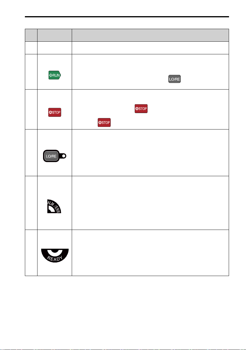
Sym
bol
A USB Terminal
B
C
D
E
F
Name Function
RUN Key
STOP Key
LO/RE LED
ALM/ERR LED
READY LED
1 English
Table 1.1 Keypad: Names and Functions
Insertion point for a USB cable. Uses a USB cable (USB standard 2.0, type A - mini-B) to
connect the keypad to a PC.
Starts the drive in LOCAL Mode.
Starts the operation in Auto-Tuning Mode.
Note:
Before you use the keypad to operate the motor, push on the keypad to set the
drive to LOCAL Mode.
Stops drive operation.
Note:
Uses a stop-priority circuit. Push to stop the motor. This will also stop the motor
when a Run command is active at an external Run command source (REMOTE Mode).
To disable priority, set o2-02 = 0 [STOP Key Function Selection = Disabled].
Illuminated: The keypad controls the Run command (LOCAL Mode).
OFF: The control circuit terminal or serial transmission device controls the Run command
(REMOTE Mode).
Note:
• LOCAL: Operated using the keypad. Use the keypad to enter Run/Stop commands and
the frequency reference command.
• REMOTE: Operated from the control circuit terminal or serial transmission. Use the
frequency reference source entered in b1-01 and the Run command source selected in
b1-02.
Illuminated: The drive detects a fault.
OFF: There are no drive faults or alarms.
Flashing:
• An alarm
• Operation Errors
• An Auto-Tuning error
Note:
The LED will illuminate to identify a fault if the drive detects a fault and an alarm at the
same time.
Illuminated: The drive is operating or is prepared for operation.
OFF:
• The drive detects a fault.
• There is no fault and the drive received a Run command, but the drive cannot operate. For
example, in Programming Mode.
Flashing: The drive is in STo [Safe Torque OFF] state.
Flashing quickly: The voltage of the main circuit power supply decreased, and the external 24
V power supply provides the only power to the drive.
YASKAWA TOMPC71061753A YASKAWA AC Drive GA500 Installation and Operation Instruction 15
Page 16
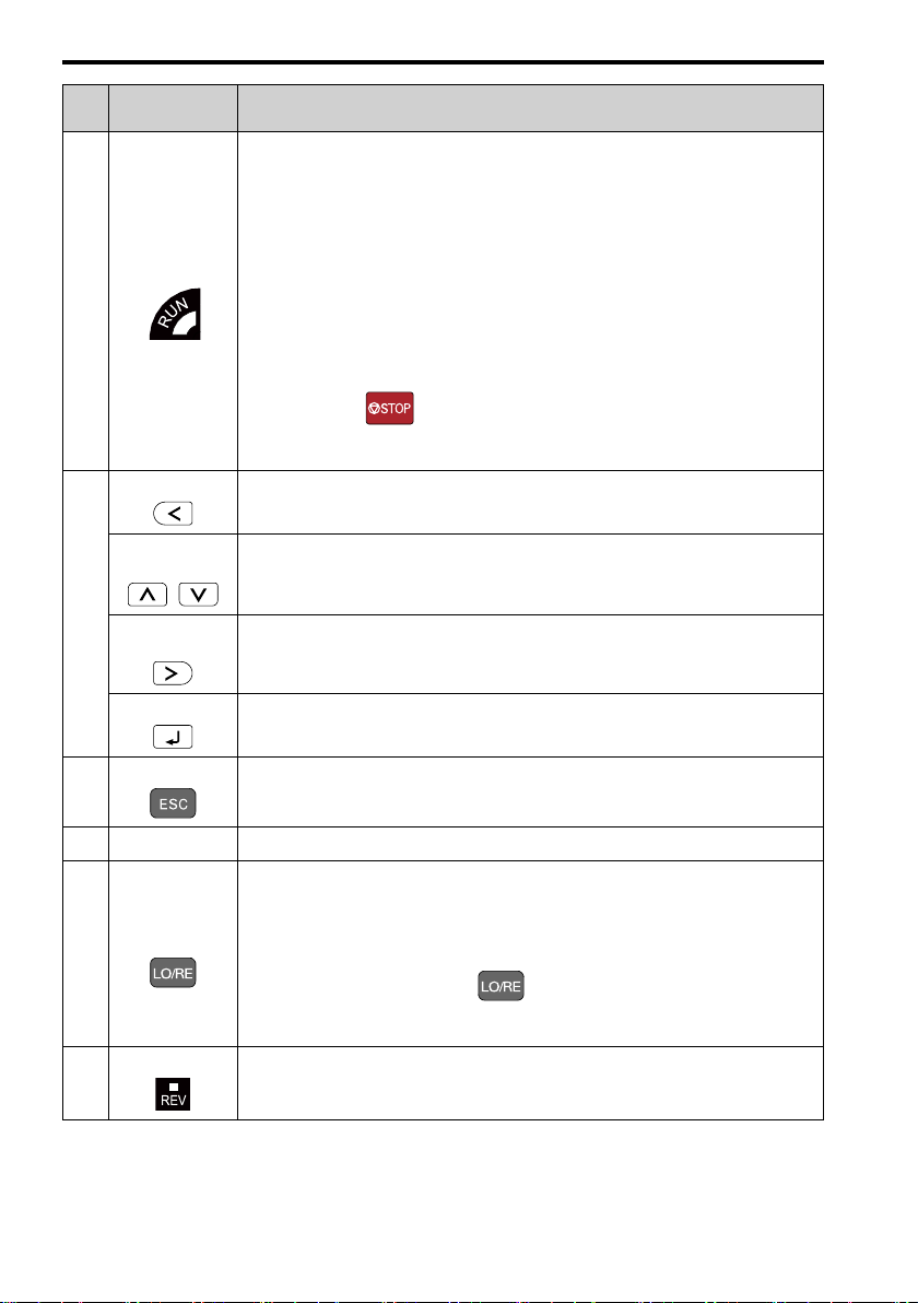
1 English
Sym
bol
G
H
Name Function
Illuminated: The drive is in regular operation.
OFF: The drive is stopped.
Flashing:
• The drive is decelerating to stop.
• The drive received a Run command, but the frequency reference is 0 Hz.
RUN LED
Left Arrow Key Moves the cursor to the left.
Up Arrow Key/
Down Arrow Key
/
Right Arrow Key
(RESET)
ENTER Key • Enters parameter values and settings.
Flashing quickly:
• The drive received a Run command from the MFDI terminals and is switching to
REMOTE Mode while the drive is in LOCAL Mode.
• The drive received a Run command from the MFDI terminals when the drive is not in
Drive Mode.
• The drive received a Fast Stop command.
• The safety function shuts off the drive output.
• The user pushed on the keypad while the drive is operating in REMOTE Mode.
• The drive is energized with an active Run command and b1-17 = 0 [Run Command at
Power Up = Disregard Existing RUN Command].
• Moves to a different screen.
• Selects parameter numbers and increments or decrements setting values.
• Moves the cursor to the right.
• Restarts the drive to clear a fault.
• Selects each mode, parameter, and set value.
ESC Key • Goes back to the previous screen.
I
J LED Display
LO/RE Selection
K
L
16 YASKAWA TOMPC71061753A YASKAWA AC Drive GA500 Installation and Operation Instruction
Key
REV LED Illuminated: The drive received a Reverse run command.
• Push and hold to go back to the frequency reference screen (the initial screen).
Shows parameters, errors, and other data.
Switches drive control for the Run command and frequency reference between the keypad
(LOCAL) and an external source (REMOTE).
Note:
• The LOCAL/REMOTE Selection Key continuously stays enabled after the drive stops
in Drive Mode. If the application must not switch from REMOTE to LOCAL because it
will have a negative effect on system performance, set o2-01 = 0 [LO/RE Key Function
Selection = Disabled] to disable .
• The drive will not switch between LOCAL and REMOTE when it is receiving a Run
command from an external source.
Page 17

1 English
Sym
bol
M
N RJ-45 Connector
REMOTE Run Selection = Accept Existing RUN Command], the drive can start suddenly. Before you change the
control source, remove all personnel from the area around the drive, motor, and load. Sudden starts can cause
serious injury or death.
Name Function
DWEZ LED Illuminated: The drive is In DriveWorksEZ operation.
Connects to the drive. Use an RJ-45 8-pin straight through UTP CAT5e extension cable to
install the keypad in a different location than the drive.
WARNING
Sudden Movement Hazard. If you change the control source when b1-07 = 1 [LOCAL/
◆ Installation
WARNING
install the drive near flammable or combustible materials. Attach the drive to metal or other noncombustible
material. Flammable and combustible materials can start a fire and cause serious injury or death.
CAUTION
drive. If the drive or covers fall, it can cause moderate injury.
NOTICE
can cause incorrect operation and damage to electrical devices.
NOTICE
drive during drive installation. Put a temporary cover over the drive during installation. Remove the temporary
cover before start-up. Unwanted objects inside of the drive can cause damage to the drive.
NOTICE
Incorrect ESD procedures can cause damage to the drive circuitry.
Note:
Do not put drive peripheral devices, transformers, or other electronics near the drive. Shield the drive from electrical
interference if components must be near the drive. Components near the drive can cause incorrect drive operation from
electrical interference.
Fire Hazard. Do not put flammable or combustible materials on top of the drive and do not
Crush Hazard. Tighten terminal cover screws and hold the case safely when you move the
Install the drive as specified by EMC Guidelines. If you do not obey the EMC Guidelines, it
Do not let unwanted objects, for example metal shavings or wire clippings, fall into the
Obey correct electrostatic discharge (ESD) procedures when you touch the drive.
■ Installation Environment
The installation environment is important for the lifespan of the product and to make sure that
the drive performance is correct. Make sure that the installation environment agrees with these
specifications.
Environment
Area of Use
Power Supply
Ambient
Temperature
Setting
Humidity
Storage
Temperature
YASKAWA TOMPC71061753A YASKAWA AC Drive GA500 Installation and Operation Instruction 17
Indoors
Overvoltage Category III
IP20/UL Open Type: -10°C to +50 °C (14 °F to 122 °F)
IP20/UL Type1: -10 °C to +40 °C (14 °F to 104 °F)
• Drive reliability is better in environments that do not have wide temperature fluctuations.
• When installing the drive in an enclosure, use a cooling fan or air conditioner to keep the internal
air temperature in the permitted range.
• Do not let the drive freeze.
95%RH or less
Do not let condensation form on the drive.
-20 °C to +70 °C (-4 °F to +158 °F) (short-term temperature during transportation)
Conditions
Page 18
1 English
2
, 19.36 ft/s2)
Conditions
Environment
Surrounding Area
Altitude
Vibration
Installation
Orientation
Pollution degree 2 or less
Install the drive in an area without:
• Oil mist, corrosive or flammable gas, or dust
• Metal powder, oil, water, or other unwanted materials
• Radioactive or flammable materials.
• Harmful gas or fluids
• Salt
• Direct sunlight
Keep wood and other flammable materials away from the drive.
1000 m (3281 ft) maximum
Note:
Derate the output current by 1% for each 100 m (328 ft) to install the drive in altitudes between
1000 m to 4000 m (3281 ft to 13123 ft).
It is not necessary to derate the rated voltage in these conditions:
• Installing the drive at 2000 m (6562 ft) or lower
• Installing the drive between 2000 m to 4000 m (6562 ft to 13123 ft) and grounding the neutral
point on the power supply.
Contact Yaskawa or your nearest sales representative when not grounding the neutral point.
• 10 Hz to 20 Hz: 1 G (9.8 m/s
• 20 Hz to 55 Hz: 0.6 G (5.9 m/s
Install the drive vertically for sufficient airflow to cool the drive.
2
, 32.15 ft/s2)
■ Removing/Reattaching Covers
DANGER
drive. Before servicing, disconnect all power to the equipment and wait for the time specified on the warning label
at a minimum. The internal capacitor stays charged after the drive is de-energized. The charge indicator LED
extinguishes when the DC bus voltage decreases below 50 Vdc. When all indicators are OFF, measure for
dangerous voltages to make sure that the drive is safe. If you do work on the drive when it is energized, it will
cause serious injury or death from electrical shock. The drive has internal capacitors that stay charged after you
de-energize the drive.
Electrical Shock Hazard. Do not examine, connect, or disconnect wiring on an energized
◆ Electrical Installation
DANGER
drive. Before servicing, disconnect all power to the equipment and wait for the time specified on the warning label
at a minimum. The internal capacitor stays charged after the drive is de-energized. The charge indicator LED
extinguishes when the DC bus voltage decreases below 50 Vdc. When all indicators are OFF, remove the covers
before measuring for dangerous voltages to make sure that the drive is safe. If you do work on the drive when it is
energized, it will cause serious injury or death from electrical shock. The drive has internal capacitors that stay
charged after you de-energize the drive.
WARNING
Charge LED turns off. Remove the front cover and terminal cover to do work on wiring, circuit boards, and other
parts. Use terminals for their correct function only. Incorrect wiring, incorrect ground connections, and incorrect
repair of protective covers can cause death or serious injury.
WARNING
switch. If you touch electrical equipment that is not grounded, it can cause serious injury or death.
WARNING
Refer to the technical manual for more information about the I/O terminals. Wiring and grounding incorrectly or
modifying the cover may damage the equipment or cause injury.
18 YASKAWA TOMPC71061753A YASKAWA AC Drive GA500 Installation and Operation Instruction
Electrical Shock Hazard. Do not examine, connect, or disconnect wiring on an energized
Electrical Shock Hazard. De-energize the drive and wait 5 minutes minimum until the
Electrical Shock Hazard.. Correctly ground the drive before you turn on the EMC filter
Electrical Shock Hazard. Use the terminals for the drive only for their intended purpose.
Page 19

1 English
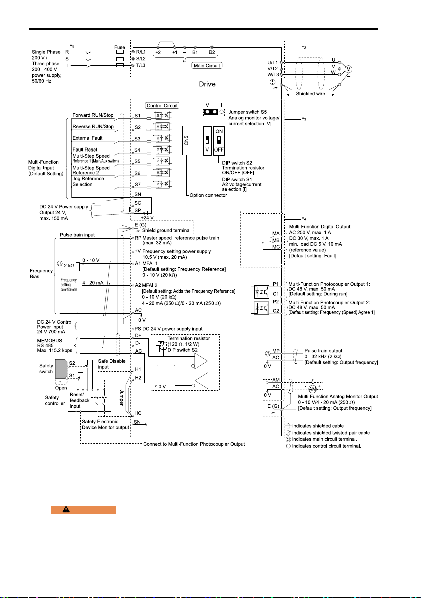
■ Standard Connection Diagram
Wire the drive as specified by Figure 1.2.
WARNING
switches. Incorrect Run/Stop circuit sequence settings can cause serious injury or death from moving equipment.
WARNING
energize the drive. If you momentarily close a digital input terminal, it can start a drive that is programmed for 3Wire control and cause serious injury or death from moving equipment.
WARNING
Parameters = 3-Wire Initialization] and make sure that b1-17 = 0 [Run Command at Power Up = Disregard
Existing RUN Command] (default). If you do not correctly set the drive parameters for 3-Wire operation before
you energize the drive, the motor can suddenly rotate in reverse when you energize the drive.
WARNING
drive before you set the Application Preset function. When you set the Application Preset function (A1-06 ≠ 0), it
changes the I/O terminal functions for the drive and it can cause equipment to operate unusually. This can cause
serious injury or death.
WARNING
applicable codes and this manual. The drive is suited for circuits that supply not more than 31,000 RMS
symmetrical amperes, 240 Vac maximum (200 V Class), 480 Vac maximum (400 V Class). Incorrect branch
circuit short circuit protection can cause serious injury or death.
NOTICE
ft), make sure that the motor insulation voltage is sufficient or use an inverter-duty motor or vector-duty motor with
reinforced insulation. Motor winding and insulation failure can occur.
Note:
Do not connect the AC control circuit ground to the drive enclosure. Failure to obey can cause incorrect control circuit
operation.
Sudden Movement Hazard. Set the MFDI parameters before you close control circuit
Sudden Movement Hazard. Correctly wire the start/stop and safety circuits before you
Sudden Movement Hazard. When you use a 3-Wire sequence, set A1-03 = 3330 [Initialize
Sudden Movement Hazard. Check the I/O signals and the external sequences for the
Fire Hazard. Install sufficient branch circuit short circuit protection as specified by
When the input voltage is 440 V or higher or the wiring distance is longer than 100 m (328
YASKAWA TOMPC71061753A YASKAWA AC Drive GA500 Installation and Operation Instruction 19
Page 20
1 English
Figure 1.2 Standard Drive Connection Diagram
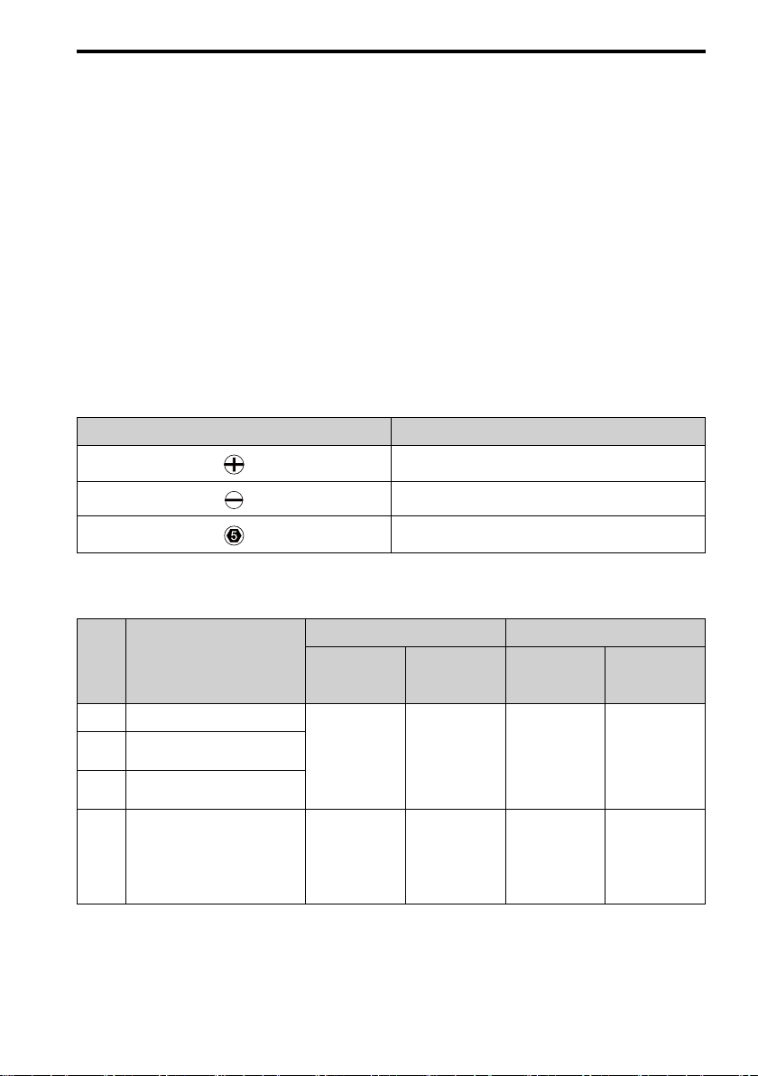
*1 For three-phase 200 V class and 400 V class drives, use terminals -, +1, +2, B1, and B2 to
connect options to the drive. For single-phase 200 V class drives, use terminals -, +1, B1,
and B2 to connect options to the drive.
WARNING
terminals B1, B2, -, +1, +2, and +3 terminals. Do not connect AC power to these terminals. Incorrect wiring
can cause damage to the drive and serious injury or death from fire.
20 YASKAWA TOMPC71061753A YASKAWA AC Drive GA500 Installation and Operation Instruction
Fire Hazard. Only connect factory-recommended devices or circuits to drive
Page 21
1 English
*2 For circuit protection, the main circuit is separated from the surface case that can touch
the main circuit.
*3 The control circuit is a Safety Extra-Low Voltage circuit. Separate this circuit from other
circuits with reinforced insulation. Make sure that the Safety Extra-Low Voltage circuit is
connected as specified.
*4 Reinforced insulation separates the output terminals from other circuits. Users can also
connect circuits that are not Safety Extra-Low Voltage circuits if the drive output is 250
Vac 1 A maximum or 30 Vdc 1 A maximum.
*5 Set L8-05 = 1 [Output Phase Loss Protect Select = Enabled] or set the wiring sequence to
prevent input phase loss.
■ Wire Selection
Select the correct wires for main circuit wiring.
Refer to Main Circuit Wire Gauges and Tightening Torques (for CE Standards) on page 283 for
wire gauges and tightening torques as specified by European standards.
Refer to Main Circuit Wire Gauges and Tightening Torques (for UL Standards) on page 296 for
wire gauges and tightening torques as specified by UL standards.
Table 1.2 Icons to Identify Screw Shapes
Icon Screw Shape
+/-
Slotted (-)
Hex socket cap (WAF: 5 mm)
■ Control Circuit Wire Gauges and Tightening Torques
Table 1.3 Control Circuit Wire Gauges and Tightening Torques
Termi
nal
Block
TB1-1 PS, S1 - S7, SN, SC, SP
AM, AC, A1, A2, +V, H1, H2,
TB1-2
HC
MP, RP, AC, D+, D-, P1, C1, P2,
TB1-3
C2
TB2 MA, MB, MC
Terminal
Recommended
mm
Crimp Ferrules
Attach an insulated sleeve when you use crimp ferrules. Refer to Table 1.4 for the recommended
external dimensions and model numbers of the crimp ferrules.
Use the CRIMPFOX 6, a crimping tool made by PHOENIX CONTACT.
YASKAWA TOMPC71061753A YASKAWA AC Drive GA500 Installation and Operation Instruction 21
Bare Wire Crimp Ferrule
Gauge
2
(AWG)
0.75
(18)
0.75
(18)
Applicable
Gauge
mm2(AWG)
• Stranded wire
0.25 - 1.0
(24 - 17)
• Solid wire
0.25 - 1.5
(24 - 16)
• Stranded wire
0.25 - 1.5
(24 -16)
• Solid wire
0.25 - 1.5
(24 - 16)
Recommended
Gauge
mm2(AWG)
0.5
(20)
0.5
(20)
Applicable
Gauge
mm2(AWG)
0.25 - 0.5
(24 - 20)
0.25 - 1.0
(24 - 17)
Page 22
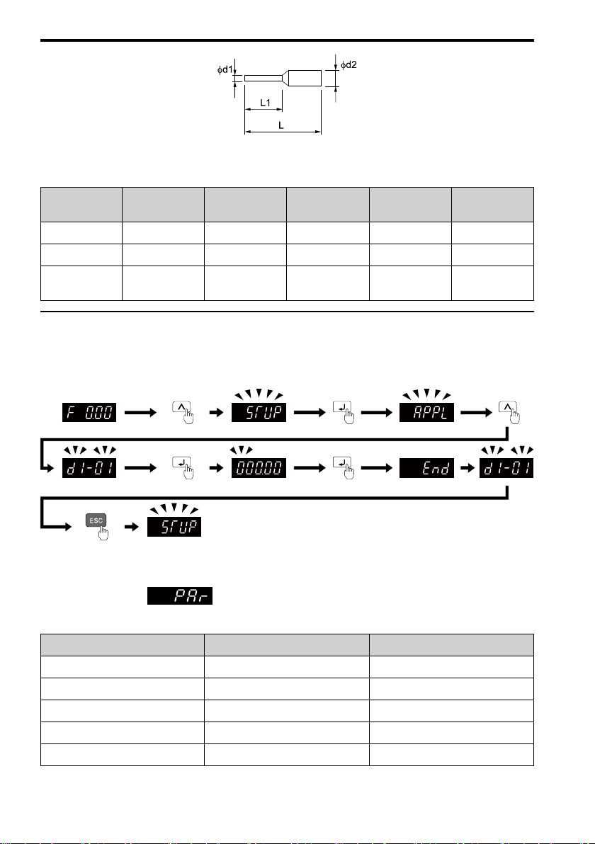
1 English
Figure 1.3 External Dimensions of Crimp Ferrules
Table 1.4 Crimp Ferrule Models and Sizes
Wire Gauge
2
(AWG)
mm
0.25 (24) AI 0.25-8YE 12.5 8 0.8 2.0
0.34 (22) AI 0.34-8TQ 12.5 8 0.8 2.0
0.5 (20)
Model L (mm) L1 (mm) φd1 (mm) φd2 (mm)
AI 0.5-8WH,
AI 0.5-8OG
14 8 1.1 2.5
◆ Drive Start-Up
■ Set up the Drive with General-Purpose Setup Mode
Drive parameters are in letter groups from A to U. Setup Mode [STUP] contains only the most
frequently used parameters to help you set up the drive more easily.
Figure 1.4 Parameters in General-Purpose Setup Mode
Table 1.5 shows the parameters available in Setup Mode. To access parameters not shown in the
Setup Mode, use the menu.
Table 1.5 Parameters in General-Purpose Setup Mode
User Parameters Parameter Name
A2-01 A1-02 Control Method Selection
A2-02 b1-01 Frequency Reference Selection 1
A2-03 b1-02 Run Command Selection 1
A2-04 b1-03 Stopping Method Selection
A2-05 C1-01 Acceleration Time 1
22 YASKAWA TOMPC71061753A YASKAWA AC Drive GA500 Installation and Operation Instruction
Page 23
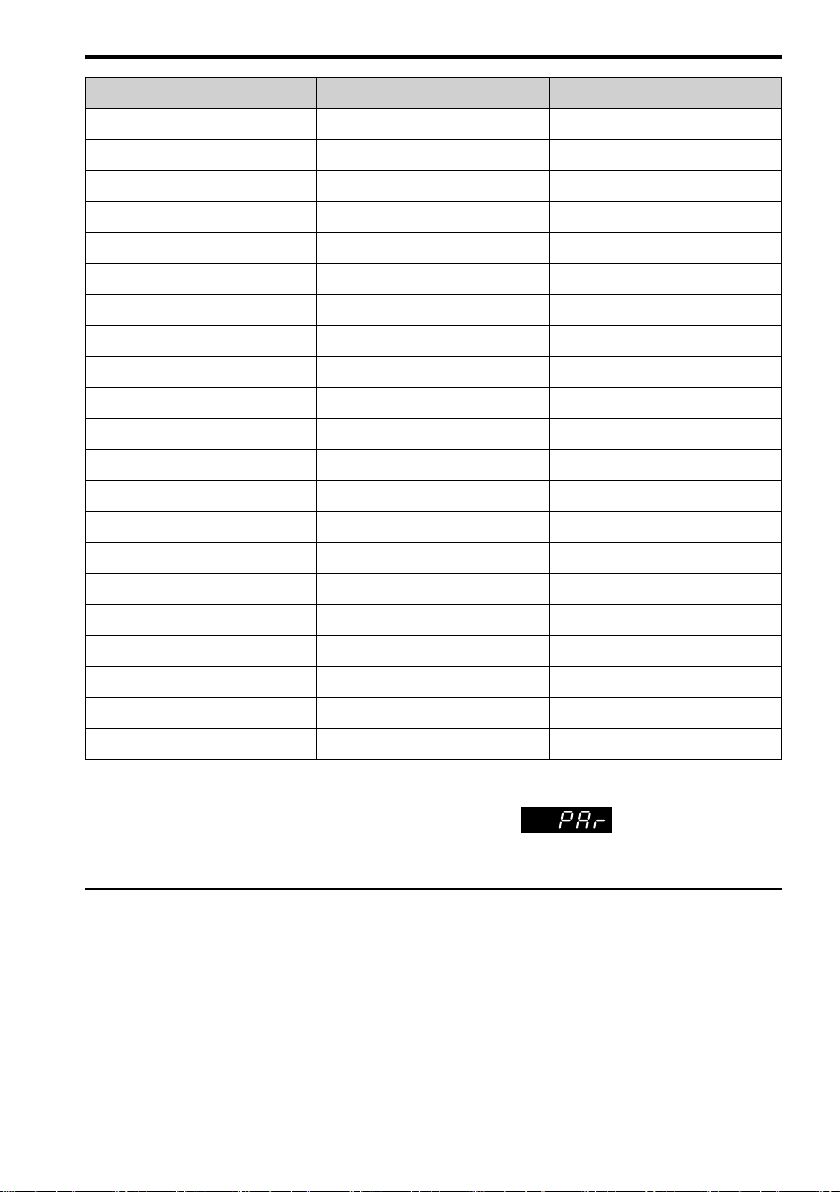
User Parameters Parameter Name
A2-06 C1-02 Deceleration Time 1
A2-07 C6-01 Normal / Heavy Duty Selection
A2-08 C6-02 Carrier Frequency Selection
A2-09 d1-01 Reference 1
A2-10 d1-02 Reference 2
A2-11 d1-03 Reference 3
A2-12 d1-04 Reference 4
A2-13 d1-17 Jog Reference
A2-14 E1-01 Input AC Supply Voltage
A2-15 E1-03 V/f Pattern Selection
A2-16 E1-04 Maximum Output Frequency
A2-17 E1-05 Maximum Output Voltage
A2-18 E1-06 Base Frequency
A2-19 E1-09 Minimum Output Frequency
A2-20 E1-13 Base Voltage
A2-21 E2-01 Motor Rated Current (FLA)
A2-22 E2-04 Motor Pole Count
A2-23 E2-11 Motor Rated Power
A2-24 H4-02 Terminal AM Analog Output Gain
A2-25 L1-01 Motor Overload (oL1) Protection
A2-26 L3-04 Stall Prevention during Decel
Note:
• When you change A1-02 [Control Mode Selection], the settings of some parameters automatically change.
1 English
• This manual also shows parameters that are not in Setup Mode. Use the to set the parameters not
shown in the Setup Mode.
• Display parameters change when the A1-06 [Application Preset] setting changes.
◆ Drive Parameters
Refer to the following table when you set the most important parameters.
Note:
You can change parameters that have “RUN” in the “No.” column during drive operation.
YASKAWA TOMPC71061753A YASKAWA AC Drive GA500 Installation and Operation Instruction 23
Page 24

1 English
No.
(Hex.)
A1-02 Control Method
A1-03 Initialize Parameters Sets parameters to default values.
b1-01 Frequency Reference
b1-02 Run Command
b1-03 Stopping Method
b1-04 Reverse Operation
C1-01
RUN
C1-02
RUN
C2-01 S-Curve Time @ Start
C2-02 S-Curve Time @ End
C2-03 S-Curve Time @ Start
C2-04 S-Curve Time @ End
C6-01 Normal / Heavy Duty
C6-02 Carrier Frequency
d1-01 - d1-16
RUN
d1-17
RUN
d2-01 Frequency Reference
Name Description
Selection
Selection 1
Selection 1
Selection
Selection
Acceleration Time 1 Sets the length of time to accelerate from zero to maximum output frequency.
Deceleration Time 1 Sets the length of time to decelerate from maximum output frequency to zero.
of Accel
of Accel
of Decel
of Decel
Selection
Selection
Reference 1 to 16 Sets the frequency reference in the units from o1-03 [Frequency Display Unit
Jog Reference Sets the Jog frequency reference in the units from o1-03 [Frequency Display
Upper Limit
Sets the control method for the drive application and the motor.
0: V/f Control, 2: Open Loop Vector, 5: PM Open Loop Vector,
6: PM Advanced Open Loop Vector, 8: EZ Vector Control
0: No Initialization, 1110: User Initialization, 2220: 2-Wire Initialization,
3330: 3-Wire Initialization
Sets the input method for the frequency reference.
0: Keypad, 1: Analog Input, 2: Memobus/Modbus Communications,
3: Option PCB, 4: Pulse Train Input
Sets the input method for the Run command.
0: Keypad, 1: Digital Input, 2: Memobus/Modbus Communications,
3: Option PCB
Sets the method to stop the motor after removing a Run command or entering a
Stop command.
0: Ramp to Stop, 1: Coast to Stop, 2: DC Injection Braking to Stop,
3: Coast to Stop with Timer, 9: Stop with Constant Distance
Sets the reverse operation function. Disable reverse operation in fan or pump
applications where reverse rotation is dangerous.
0: Reverse Enabled, 1: Reverse Disabled
Sets the S-curve acceleration time at start.
Sets the S-curve acceleration time at completion.
Sets the S-curve deceleration time at start.
Sets the S-curve deceleration time at completion.
Sets the drive duty rating.
0: Heavy Duty Rating, 1: Normal Duty Rating
Sets the carrier frequency for the transistors in the drive.
1: 2.0 kHz, 2: 5.0 kHz (4.0 kHz AOLV/PM), 3: 8.0 kHz (6.0 kHz AOLV/PM),
4: 10.0 kHz (8.0 kHz AOLV/PM), 5: 12.5 kHz (10.0 kHz AOLV/PM),
6: 15.0 kHz (12.0 kHz AOLV/PM), 7: Swing PWM4 (Audible Sound 1),
8: Swing PWM4 (Audible Sound 2), 9: Swing PWM4 (Audible Sound 3),
A: Swing PWM4 (Audible Sound 4), B: Leakage Current Rejection PWM,
F: User Defined (C6-03 to C6-05)
Selection.
Unit Selection]. Set H1-xx = 6 [MFDI Function Select = Jog Reference
Selection] to use the Jog frequency reference.
Sets maximum limit for all frequency references. The maximum output
frequency is 100%.
24 YASKAWA TOMPC71061753A YASKAWA AC Drive GA500 Installation and Operation Instruction
Page 25

1 English
No.
(Hex.)
d2-02 Frequency Reference
E1-01 Input AC Supply
E1-04 Maximum Output
E1-05 Maximum Output
E1-06 Base Frequency Sets the base frequency for the V/f pattern.
E1-09 Minimum Output
E2-01 Motor Rated Current Sets the motor rated current in amps.
E2-11 Motor Rated Power Sets the motor rated output in the units from o1-58 [Motor Power Unit
H1-01 - H1-07Terminal S1 to S7
H2-01 Term MA/MB-MC
H2-02 Term P1-C1 Function
H2-03 Term P2-C2 Function
H3-01 Terminal A1 Signal
H3-02 Terminal A1 Function
H3-03
RUN
H3-04
RUN
H3-09 Terminal A2 Signal
H3-10 Terminal A2 Function
H3-11
RUN
H3-12
RUN
H3-13 Analog Input
Name Description
Lower Limit
Voltage
Frequency
Voltage
Frequency
Function Selection
Function Selection
Selection
Selection
Level Select
Selection
Terminal A1 Gain
Setting
Terminal A1 Bias
Setting
Level Select
Selection
Terminal A2 Gain
Setting
Terminal A2 Bias
Setting
FilterTime Constant
Sets minimum limit for all frequency references. The maximum output
frequency is 100%.
Sets the drive input voltage.
Sets the maximum output frequency for the V/f pattern.
Sets the maximum output voltage for the V/f pattern.
Sets the minimum output frequency for the V/f pattern.
Selection].
Sets functions for MFDI terminals S1 to S7.
Sets a function for MFDO terminal MA-MC or MB-MC.
Sets a function for MFDO terminal P1-C1.
Sets a function for MFDO terminal P2-C2.
Sets the input signal level for MFAI terminal A1.
0: 0 to 10V (Lower Limit at 0), 1: 0 V to 10 V (Without Lower Limit)
Sets a function for MFAI terminal A1.
Sets the gain of the analog signal input to MFAI terminal A1.
Sets the bias of the analog signal input to MFAI terminal A1.
Sets the input signal level for MFAI terminal A2.
0: 0-10V (LowLim=0), 1: 0 V to 10 V (Without Lower Limit), 2: 4 to 20 mA,
3: 0 to 20 mA
Sets a function for MFAI terminal A2.
Sets the gain of the analog signal input to MFAI terminal A2.
Sets the bias of the analog signal input to MFAI terminal A2.
Sets the time constant to apply a primary delay filter to the MFAI terminal.
YASKAWA TOMPC71061753A YASKAWA AC Drive GA500 Installation and Operation Instruction 25
Page 26
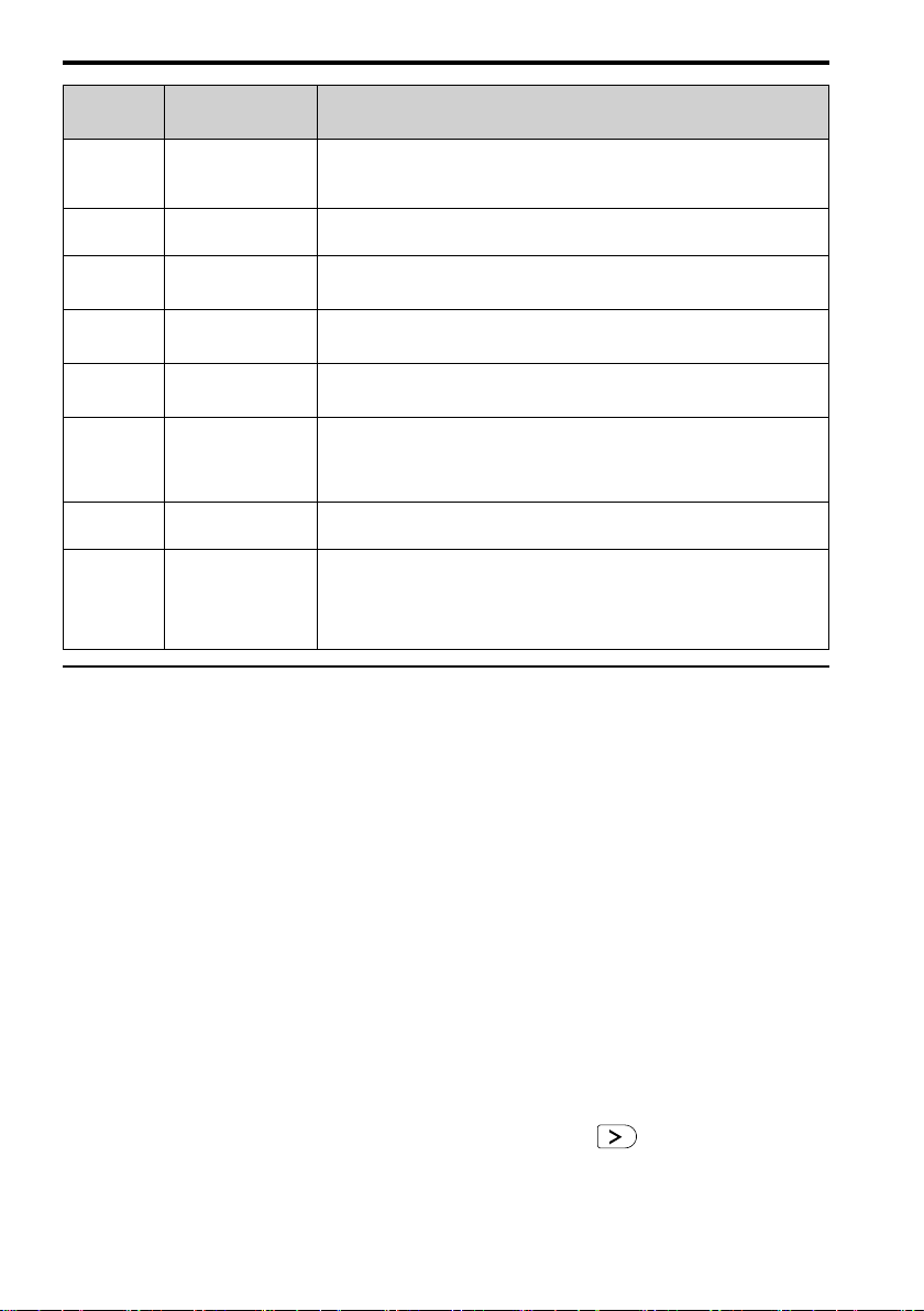
1 English
No.
(Hex.)
H3-14 Analog Input Terminal
H4-01 Terminal AM Analog
H4-02
RUN
H4-03
RUN
H4-07 Terminal AM Signal
L1-01 Motor Overload (oL1)
L1-02 Motor Overload
L3-04 Stall Prevention during
Name Description
Enable Sel
Output Select
Terminal AM Analog
Output Gain
Terminal AM Analog
Output Bias
Level Select
Protection
Protection Time
Decel
Sets the enabled terminal or terminals when H1-xx = C [MFDI Function Select
= Analog Terminal Enable Selection] is ON.
1: Terminal A1 only, 2: Terminal A2 only, 7: All Terminals Enabled
Sets the monitoring number to be output from the MFAO terminal AM.
Sets the gain of the monitor signal that is sent from MFAO terminal AM.
Sets the bias of the monitor signal that is sent from MFAO terminal AM.
Sets the MFAO terminal AM output signal level.
0: 0 to 10 V, 2: 4 to 20 mA
Sets the motor overload protection with electronic thermal protectors.
0: No, 1: Variable Torque, 2: Constant Torque 10:1 Speed Range,
3: Constant Torque 100:1 SpeedRange, 4: PM Variable Torque,
5: PM Constant Torque, 6: Variable Torque (50Hz)
Sets the operation time for the electronic thermal protector of the drive to
prevent damage to the motor. Usually it is not necessary to change this setting.
Sets the method that the drive will use to prevent overvoltage faults when
decelerating.
0: No, 1: General Purpose, 2: Intelligent (Ignore Decel Ramp),
3: General Purpose w/ DB resistor, 4: Overexcitation/High Flux,
5: Overexcitation/High Flux 2, 7: Overexcitation/High Flux 3
◆ Troubleshooting
If the drive or motor do not operate correctly, look at the drive keypad for fault and alarm
information.
• For drive faults:
– The keypad shows the fault code.
– ALM/ERR LED stays illuminated.
– The drive shuts off output, and the output terminal set for Fault [H2-01 to H2-03 = E]
activates. The motor coasts to stop.
• For drive alarms:
– The keypad shows the alarm code.
– ALM/ERR LED flashes.
– The drive will continue to operate the motor. Some alarms let you select a motor stopping
method.
■ Fault Reset Procedure
1. Remove the cause of the alarm or fault.
2. While the keypad is showing the fault or alarm code, push on the keypad.
This table gives information about the causes and possible solutions of the most frequent faults
and alarms.
26 YASKAWA TOMPC71061753A YASKAWA AC Drive GA500 Installation and Operation Instruction
Page 27

Refer to the technical manual for a complete list of all faults and alarms.
Code Name Causes Possible Solutions
bb Baseblock
CrST Cannot Reset
FWD/REV Run
EF
Command Input Error
EF1 - EF7
External Fault
(Terminal Sx)
GF Ground Fault
oC Overcurrent
oL1 Motor Overload
An external baseblock command
was entered through one of the
MFDI terminals Sx, and the drive
output stopped as shown by an
external baseblock command.
The drive received a fault reset
command when a Run command
was active.
A forward command and a reverse
command were input at the same
time for longer than 0.5 s.
MFDI terminal Sx caused an
external fault through an external
device.
External Fault [H1-xx = 20 to 2B]
is set to MFDI terminal, but the
terminal is not in use.
Overheating caused damage to the
motor or the motor insulation is
not satisfactory.
The motor main circuit cable is
contacting ground to make a short
circuit.
An increase in the stray
capacitance of the cable and the
ground terminal caused an
increase in the leakage current.
There was a problem with the
drive hardware.
• The motor main circuit cable is
contacting ground to make a
short circuit.
• The load is too large.
• The acceleration time is too
short.
• The V/f pattern settings are
incorrect.
• The motor data is incorrect.
• A magnetic contactor was
switched at the output.
The motor load is too large. Decrease the motor load.
The drive is operating a generalpurpose motor with a high load at
lower speed than the rated speed.
Examine the external sequence and timing
of the baseblock command input.
Turn off the Run command then de-energize
and re-energize the drive.
Examine the forward and reverse command
sequence and correct the problem.
• Remove the cause of the external fault to
clear the external fault input in the
MFDI.
• Correctly set the MFDI.
Measure the motor insulation resistance, and
replace the motor if there is electrical
conduction or unserviceable insulation.
• Examine the motor main circuit cable for
damage, and repair short circuits.
• Measure the resistance between the
motor main circuit cable and the ground
terminal. If there is electrical conduction,
replace the cable.
• If the wiring length of the cable is more
than 100 m, decrease the carrier
frequency.
• Decrease the stray capacitance.
Replace the control board or the drive. For
information about replacing the control
board, contact Yaskawa or your nearest sales
representative.
• Replace damaged output cables or motor
cables.
• Repair damaged devices.
• Make sure that the parameter settings are
correct.
• Make sure that the sequence of the
electromagnetic contactor on the drive
output side is correct.
Use a motor with an external cooling fan
and set the correct motor type to L1-01
[Motor Overload (oL1) Protection].
1 English
YASKAWA TOMPC71061753A YASKAWA AC Drive GA500 Installation and Operation Instruction 27
Page 28

1 English
oL2 Drive Overload
ov Overvoltage
PF Input Phase Loss
STo Safe Torque OFF
The acceleration/deceleration
times or cycle times are too short.
The setting of the motor rated
current is incorrect.
• The load is too large.
• The drive capacity is too small.
• The torque is too large at low
speed.
• The power supply voltage is
too high.
• The deceleration time is too
short.
• The stall prevention function is
disabled.
• The braking resistor is not
connected or is broken.
• Motor control is not stable.
• The input voltage is too high.
There is a phase loss in the drive
input power.
Loose wiring in the input power
terminals.
The drive input power voltage is
changing too much.
Unsatisfactory balance between
voltage phases.
The main circuit capacitors have
become unserviceable.
Safe Disable inputs H1-HC and
H2-HC are open.
Increase the acceleration and deceleration
times.
Make sure that the rated current set in E2-01
[Motor Rated Current (FLA)] is correct.
• Examine the load.
• Make sure that the drive is large enough
for the load.
• The overload capability of the drive
decreases at low speeds. Decrease the
load or replace the drive with a larger
capacity drive.
• Increase the deceleration time.
• Set L3-04 ≠ 0 [Stall Prevention during
Decel ≠ Disabled] to enable stall
prevention.
• Replace the braking resistor.
• Make sure that the motor parameter
settings are correct, and adjust the torque
and slip compensation if necessary.
• Make sure that the supply voltage is
correct for the drive specifications.
Correct all wiring errors with the main
circuit power supply.
Tighten the screws to the correct tightening
torque.
• Examine the supply voltage for
problems.
• Make the drive input power stable.
• Examine the supply voltage for
problems.
• Make the drive input power stable.
• If the supply voltage is good, examine
the magnetic contactor on the main
circuit side for problems.
• Examine the capacitor maintenance time
in monitor U4-05
[CapacitorMaintenance].
• If U4-05 is more than 90%, replace the
capacitor. Contact Yaskawa or your
nearest sales representative for more
information.
• Examine the supply voltage for
problems.
• Re-energize the drive.
• If the alarm stays, replace the circuit
board or the drive. For information about
replacing the control board, contact
Yaskawa or your nearest sales
representative.
• Make sure that the Safe Disable signal is
input from an external source to terminal
H1-HC and H2-HC.
• When the Safe Disable function is not in
use, connect terminals H1-HC and H2HC.
28 YASKAWA TOMPC71061753A YASKAWA AC Drive GA500 Installation and Operation Instruction
Page 29
1 English
SToF
Safe Torque OFF
Failure
One of the two terminals H1-HC
and H2-HC received the Safe
Disable input signal.
The Safe Disable input signal is
wired incorrectly.
There is internal damage to one
Safe Disable channel.
• Make sure that the Safe Disable signal is
input from an external source to
terminals H1-HC or H2-HC.
• When the Safe Disable function is not in
use, connect terminals H1-HC and H2HC.
Replace the board or the drive. For
information about replacing the control
board, contact Yaskawa or your nearest sales
representative.
◆ Disposal
■ Disposal Instructions
Correctly dispose of the drive and packing material as specified by applicable regional, local,
and municipal laws and regulations.
■ WEEE Directive
The wheelie bin symbol on this product, its manual, or its packaging identifies that you must
recycle it at the end of its product life.
You must discard the product at an applicable collection point for electrical and electronic
equipment (EEE). Do not discard the product with usual waste.
◆ European Standards
Figure 1.5 CE Mark
The CE Mark identifies that the product meets environmental and safety standards in the
European Union. Products manufactured, sold, or imported in the European Union must display
the CE Mark.
European Union standards include standards for electrical appliances (Low Voltage Directive),
standards for electrical noise (EMC Directive), and standards for machinery (Machinery
Directive).
This product displays the CE Mark in accordance with the Low Voltage Directive, the EMC
Directive, and the Machinery Directive.
YASKAWA TOMPC71061753A YASKAWA AC Drive GA500 Installation and Operation Instruction 29
Page 30

1 English
Table 1.6 Harmonized Standard
European Directive Harmonized Standard
CE Low Voltage Directive Compliance
2014/35/EU
EMC Directive
2014/30/EU
Machinery Directive
2006/42/EC
IEC/EN 61800-5-1:2007
EN 61800-3: 2004+A1:2012
• EN ISO 13849-1:2015 (PL e (Cat.III))
• IEC 62061(ed.1);am1;am2 (SILCL3)
• EN 62061:2005/A2:2015 (SILCL3)
• IEC/EN 61800-5-2:2016
The customer must display the CE Mark on the final device containing this product. Customers
must verify that the final device complies with EU standards.
■ CE Low Voltage Directive Compliance
It has been confirmed that this product complies with the CE Low Voltage Directive by
conducting a test according to IEC/EN 61800-5-1:2007.
The following conditions must be satisfied for machines and devices incorporating this product
to comply with the CE Low Voltage Directive.
■ Area of Use
Install this product in a location with Overvoltage Category III and pollution degree 2 or less as
specified in IEC/CE 60664.
■ Connect a Fuse to the Input Side (Primary Side)
The drive circuit protection must comply with IEC/EN 61800-5-1:2007 for protection against a
short circuit in the internal circuitry. Connect semiconductor fuses on the input side for branch
circuit protection.
Refer to Single-Phase 200 V Class on page 280, Three-Phase 200 V Class on page 280, and
Three-Phase 400 V Class on page 281 for more information. About recommended fuses.
WARNING
immediately energize the drive or operate peripheral devices. Wait for the time specified on the warning label at a
minimum and make sure that all indicators are OFF. Then check the wiring and peripheral device ratings to find
the cause of the problem. If you do not know the cause of the problem, contact Yaskawa before you energize the
drive or peripheral devices. If you do not fix the problem before you operate the drive or peripheral devices, it can
cause serious injury or death.
Electrical Shock Hazard. After the drive blows a fuse or trips an RCM/RCD, do not
■ EMC Directive
Use drives with built-in EMC filters or install external EMC filters to the drive input side to
comply with the EMC Directive.
Drives with built-in EMC filters (models 2xxxE, BxxxE, 4xxxE) were tested in accordance with
European standard IEC/EN 61800-3:2004/A1:2012, and comply with the EMC Directive.
■ Wire Selection
Select the correct wires for main circuit wiring.
Refer to Main Circuit Wire Gauges and Tightening Torques (for CE Standards) on page 283 for
wire gauges and tightening torques as specified by European standards.
Refer to Main Circuit Wire Gauges and Tightening Torques (for UL Standards) on page 296 for
wire gauges and tightening torques as specified by UL standards.
30 YASKAWA TOMPC71061753A YASKAWA AC Drive GA500 Installation and Operation Instruction
Page 31

1 English
Table 1.7 Icons to Identify Screw Shapes
Icon Screw Shape
+/-
Slotted (-)
Hex socket cap (WAF: 5 mm)
■ Install a Drive to Conform to the EMC Directive
Install drive models 2xxxE, BxxxE, and 4xxxE with this procedure to comply with the EMC
Directive when the drive is a single unit or installed in a larger device.
1. Install the drive on a grounded metal plate.
2. Wire the drive and motor.
3. Turn on the EMC filter switch.
4. Ground the wire shielding on the drive side and motor side.
A - Drive
B - Maximum wiring length
C - Motor
Figure 1.6 Wiring the Drive and Motor
*1 The maximum wiring length between the drive and motor is: Keep the wire as
short as possible.
2xxxE, 4xxxE: 20 m (65.6 ft)
BxxxE: 10 m (32.8 ft)
D - Metal conduit
*1
E - Grounding wire
5. Use a cable clamp to ground the motor cable to the metal plate.
Note:
Make sure that the protective ground wire complies with technical specifications or local safety standards.
6. Connect an AC reactor or DC reactor to decrease harmonic distortion.
Note:
To maintain compliance with IEC/EN 61000-3-2 on drive models 2001 to 2006, 4001 to 4004, install a DC
reactor.
YASKAWA TOMPC71061753A YASKAWA AC Drive GA500 Installation and Operation Instruction 31
Page 32

1 English
■ Enable the Internal EMC Filter
On drive models 2xxxE, BxxxE, and 4xxxE, move the screw or screws to turn ON and OFF
(enable and disable) the EMC filter.
Make sure that the symmetric grounding network is applied, and install the screw or screws in
the ON position to enable the built-in EMC filter in compliance with the EMC Directive. The
EMC filter switch screw or screws are installed in the OFF position by default.
WARNING
the warning label, and check the drive for dangerous voltages before you remove covers or touch EMC filter
screws. If you touch the screws when there are dangerous voltages, it will cause serious injury or death.
WARNING
energized. If you touch the internal components of an energized drive, it can cause serious injury or death.
WARNING
2xxxE, BxxxE, and 4xxxE to comply with the EMC Directive before you turn on the EMC filter or if there is high
resistance grounding. If the EMC filter is switched ON without the neutral point being grounded or if there is high
resistance grounding, it can cause death or serious injury.
WARNING
equipment that is not grounded, it can cause serious injury or death.
NOTICE
specified torque. If you fully remove the screws or tighten the screws to an incorrect torque, it can cause drive
failure.
NOTICE
symmetrically grounded. If the screws are not in the correct position, it can cause damage to the drive.
Electrical Shock Hazard. Disconnect all power to the drive, wait for the time specified on
Electrical Shock Hazard. Do not remove covers or touch circuit boards while the drive is
Electrical Shock Hazard. Ground the neutral point on the power supply of drive models
Electrical Shock Hazard. Connect the ground cable correctly. If you touch electrical
To disable the internal EMC filter, move the screws from ON to OFF and then tighten to the
Move the EMC switch screw or screws to the OFF position for networks that are not
Figure 1.7 Symmetric Grounding
NOTICE
grounding network, put the EMC Filter screw or screws in the OFF position to disable the built-in EMC filter.
Failure to obey the instructions can damage the drive.
When you use the drive with a non-grounding, high-resistance grounding, or asymmetric-
If you lose an EMC filter switch screw, use Table 1.8 to find the correct replacement screw and
install the new screw with the correct tightening torque.
NOTICE
can cause damage to the drive.
32 YASKAWA TOMPC71061753A YASKAWA AC Drive GA500 Installation and Operation Instruction
Only use the screws specified in this manual. If you use screws that are not approved, it
Page 33

1 English
Table 1.8 Screw Sizes and Tightening Torques
Model Screw Size
B001 - B004
2001 - 2006
B006 - B012
2010 - 2021
4001 - 4012
2030 - 2082
4018 - 4060
M3 × 16
M3 × 20
M4 × 20
Tightening Torque
N∙m (in∙lb)
0.5 - 0.6
(4.4 - 5.3)
0.5 - 0.6
(4.4 - 5.3)
1.2 - 1.5
(10.6 - 13.3)
◆ Safe Disable Input
Figure 1.8 TUV Mark
The TUV mark identifies that the product complies with the safety standards.
This section gives precautions to support the Safe Disable input. Contact Yaskawa for more
information.
The safety function complies with the standards shown in Table 1.9.
Table 1.9 Applied Safety Standards and Unified Standards
Safety
Standards
IEC/EN 61508:2010 (SIL3)
Functional
Safety
Machine
Safety
EMC
Note:
SIL = Safety Integrity Level.
IEC/EN 62061:2005/A2:2015 (SILCL3)
IEC/EN61800-5-2:2016 (SIL3)
ISO/EN ISO 13849-1:2015 (Cat.3, PL e)
IEC/EN 61000-6-7:2015
Unified Standards
■ Safe Disable Specifications
The Safe Disable input provides the stop function that complies with “Safe Torque Off” as
specified by IEC/EN 61800-5-2:2016. The Safe Disable input meets the requirements of EN
ISO 13849-1 and IEC/EN 61508. It also has a safety status monitor to detect safety circuit
errors.
When you install the drive as a component in a system, you must make sure that the system
complies with the applicable safety standards.
Refer to Table 1.10 for safety function specifications.
YASKAWA TOMPC71061753A YASKAWA AC Drive GA500 Installation and Operation Instruction 33
Page 34

1 English
Table 1.10 Safe Disable Specifications
Item Description
• Input: 2
Safe Disable input (H1, H2)
Signal ON level: 18 Vdc to 28 Vdc
Input/Output
Response time from when the input opens to when the
drive output stops
Response time from when the H1 and H2 terminal
inputs open to when the EDM signal operates
Less frequent operation
Failure probability
Performance level
HFT (hardware fault tolerance) N = 1
Type of subsystem Type B
MTTF
D
DCavg Medium
Mission time 10 years
Note:
EDM = External Device Monitoring
PFD = Probability of Failure on Demand
PFH = Probability of Dangerous Failure per Hour
request mode
Frequent operation request
mode or continuous mode
Signal OFF level: -4 Vdc to +4 Vdc
• Output: 1
MFDO safety monitor output for external device monitor
(EDM)
3 ms or less
30 ms or less
PFD = 1.38E
PFH = 3.35E
The Safe Disable input complies with the performance level
requirements of EN ISO 13849-1.
High
-5
-9
■ Safe Disable Circuit
The Safe Disable circuit has two isolated channels (terminals H1 and H2) that stop the output
transistors. The input can use the internal power supply of the drive.
Set the EDM function to one of the MFDO terminals [H2-xx = 21 or 121] to monitor the status
of the Safe Disable function. This is the “Safe Disable monitor output function”.
34 YASKAWA TOMPC71061753A YASKAWA AC Drive GA500 Installation and Operation Instruction
Page 35

Figure 1.9 Safe Disable Function Wiring Example
1 English
■ Enabling and Disabling the Drive Output (“Safe Torque Off”)
Refer to Figure 1.10 for an example of drive operation when as the drive changes from the "Safe
Torque Off" status to usual operation.
Figure 1.10 Safe Disable Operation
Switching from Usual Operation to “Safe Torque Off”
Turn OFF (open) safety input terminal H1 or H2 to enable the Safe Disable function. When the
Safe Disable function is enabled while the motor is operating, the drive output and motor torque
turn off and the motor always coasts to stop. The b1-03 [Stopping Method Selection] setting
does not have an effect on the stopping method.
The “Safe Torque Off” status is only possible with the Safe Disable function. Clear the Run
command to stop the drive. Turning off drive output (a baseblock condition) ≠ “Safe Torque
Off”.
YASKAWA TOMPC71061753A YASKAWA AC Drive GA500 Installation and Operation Instruction 35
Page 36

1 English
Note:
• When it is necessary to ramp to stop the motor, do not turn off terminals H1 and H2 until the motor fully stops. This
will prevent the motor from coasting to stop during usual operation.
• A maximum of 3 ms will elapse from when terminals H1 or H2 shut off until the drive switches to the "Safe Torque
Off" status. Set the OFF status for terminals H1 and H2 to hold for at least 3 ms. The drive may not be able to switch
to the “Safe Torque Off” status if terminals H1 and H2 are only open for less than 3 ms.
Going from “Safe Torque Off” to Usual Operation
The safety input will only release when there is no Run command.
• During Stop
When the Safe Disable function is triggered during stop, close the circuit between terminals
H1-HC and H2-HC to disable “Safe Torque Off”. Enter the Run command after the drive
stops correctly.
• During Run
When the Safe Disable function is triggered during run, close the circuit between terminals
H1-HC and H2-HC to disable “Safe Torque Off” after clearing the Run command. Enter the
Stop command, then enter the Run command when terminals H1 and H2 are ON or OFF.
■ Validating the Safe Disable Function
After you replace parts or do maintenance on the drive, complete all necessary wiring to start the
drive, then follow these steps to test the Safe Disable input. Keep a record of the test results.
1. When the two input channels are OFF (Open), make sure that the keypad flashes STo [Safe
Torque OFF], and make sure that the motor is not running.
2. Monitor the ON/OFF status of the input channels and make sure that MFDO set to the
EDM function operates as shown in Table 1.11.
If one or more of the these items are true, the ON/OFF status of the MFDO may not display
correctly on the keypad.
• Incorrect parameter settings.
• A problem with an external device.
• The external wiring has a short circuit or is disconnected.
• There is damage to the device.
Find the cause and repair the problem to correctly display the status.
3. Make sure that the EDM signal operates during usual operation as shown in Table 1.11.
■ Safe Disable Monitor Output Function and Keypad Display
Refer to Table 1.11 for information about the relation between the input channel status, Safety
monitor output status, and drive output status.
36 YASKAWA TOMPC71061753A YASKAWA AC Drive GA500 Installation and Operation Instruction
Page 37

1 English
Table 1.11 Safe Disable Input and External Device Monitor (EDM) Terminal Status
Input Channel Status
Input 1
(H1-HC)
ON
(Close the
circuit)
OFF
(Open)
ON
(Close the
circuit)
OFF
(Open)
Input 2
(H2-HC)
ON
(Close the
circuit)
ON
(Close the
circuit)
OFF
(Open)
OFF
(Open)
Safety Monitor
Output Status
MFDO
Terminal
(H2-xx =
21)
OFF ON
OFF ON
OFF ON
ON OFF
MFDO
Terminal
(H2-xx =
121)
Drive
Output
Status
Baseblock
(Drive
ready)
Safety
status
(STo)
Safety
status
(STo)
Safety
status
(STo)
Keypad
Display
Normally
displayed
SToF
(Flashing)
SToF
(Flashing)
STo
(Flashing)
READY
LED
READY:
Illuminated
ALM/ERR:
Flashing
ALM/ERR:
Flashing
READY:
Flashing
MEMOBUS Register
0020H
bit C bit D
0 0
1 0
1 0
0 1
Safety Function Status Monitor
The drive Safety monitor output sends a feedback signal about the status of the Safety function.
The Safety monitor output is one of the possible settings available for the MFDO terminals. If
there is damage to the Safe Disable circuit, a controller (PLC or safety relay) must read this
signal as an input signal to hold the “Safe Torque Off” status. This will help verify the condition
of the safety circuit. Refer to the manual for the safety device for more information about the
Safety function.
It is possible to switch polarity of the Safety monitor output signal with the MFDO function
settings. Refer to Table 1.11 for setting instructions.
Keypad Display
If the two input channels are OFF (Open), the keypad will flash STo [Safe Torque OFF].
If there is damage to the Safe disable circuit or the drive, the keypad will flash SToF [Safe
Torque OFF Hardware] when one input channel is OFF (Open), and the other is ON (Short
circuit). When you use the Safe disable circuit correctly, the keypad will not show SToF.
If there is damage to the drive, the keypad will show SCF [Safety Circuit Fault] when the drive
detects a fault in the Safe disable circuit. Refer to the chapter on Troubleshooting for more
information.
YASKAWA TOMPC71061753A YASKAWA AC Drive GA500 Installation and Operation Instruction 37
Page 38

2 Deutsch
2 Deutsch
◆
Allgemeine Informationen
Verwenden Sie dieses Handbuch nicht als Alternative zum Technischen Handbuch.
Die in diesem Handbuch genannten Produkte und Spezifikationen und der Inhalt des Handbuchs
können unangekündigt geändert werden, um das Produkt und das Handbuch zu verbessern.
Achten Sie darauf, dass Sie stets die aktuelle Version dieses Handbuchs verwenden. Verwenden
Sie dieses Handbuch, um das Produkt korrekt zu installieren, zu verdrahten, einzustellen und zu
bedienen.
Das Technische Handbuch kann von der Yaskawa Website für Dokumentationen heruntergeladen werden, deren Adresse Sie auf der Umschlagrückseite finden.
◆ Anwenderzielgruppe
Dieses Handbuch von Yaskawa richtet sich an Elektroingenieure und Spezialisten, die über
Erfahrung mit der Installation, der Anpassung, der Inspektion und der Wartung von Frequenzumrichtern verfügen. Personen ohne technische Ausbildung, Minderjährige, Personen mit
Behinderungen oder psychischen Erkrankungen sowie Personen mit Schrittmachern dürfen dieses Produkt weder verwenden noch betreiben.
◆ Abschnitt Sicherheit
Lesen Sie alle Sicherheitshinweise, bevor Sie den Frequenzumrichter installieren, verdrahten
oder betreiben.
■ Erläuterung der Signalwörter
WARNUNG
ter installieren, betreiben oder Wartungsmaßnahmen daran durchführen. Installieren Sie den Frequenzumrichter
entsprechend diesem Handbuch und den örtlichen Vorschriften. Die Symbole in diesem Abschnitt kennzeichnen
Sicherheitshinweise im Handbuch. Das Nichtbeachten dieser Sicherheitshinweise kann schwere oder tödliche
Verletzungen oder Schäden an den Produkten und damit verbundener Ausrüstung und Systemen zur Folge
haben.
Mit diesen Kennzeichnungen werden wichtige Sicherheitsvorkehrungen in diesen Anweisungen
kategorisiert und hervorgehoben.
GEFAHR
Verletzungen verursacht.
WARNUNG
Verletzungen verursachen kann.
VORSICHT
Verletzungen zur Folge haben kann.
HINWEIS
Verletzungsgefahr.
Machen Sie sich mit dem Inhalt dieses Handbuch vertraut, bevor Sie den Frequenzumrich-
Dieses Signalwort kennzeichnet eine Gefahr, die bei Nichtbeachten schwere oder tödliche
Dieses Signalwort kennzeichnet eine Gefahr, die bei Nichtbeachten schwere oder tödliche
Weist auf eine gefährliche Situation hin, die bei Nichtbeachten leichte oder mittelschwere
Dieses Signalwort kennzeichnet ein Risiko für Sachschäden , bedeutet jedoch keine
■ Allgemeine Sicherheitshinweise
Yaskawa Electric ist Hersteller und Anbieter von elektronischen Komponenten für verschiedene
industrielle Anwendungen. Für die Auswahl und Anwendung von Produkten von Yaskawa ist
der Konstrukteur der Ausrüstung zuständig bzw. der Kunde, der das Endprodukt fertigt. Yaskawa ist nicht dafür verantwortlich, wie seine Produkte in das endgültige Systemdesign eingebunden sind. Generell sollten Produkte von Yaskawa nicht die einzige Sicherheitsvorrichtung
eines Produkts oder einer Konstruktion darstellen. Alle Steuerfunktionen sind dafür ausgelegt,
38 YASKAWA TOMPC71061753A YASKAWA AC Drive GA500 Installation and Operation Instruction
Page 39

2 Deutsch
Fehler dynamisch zu erkennen und einen durchgängig sicheren Betrieb zu gewährleisten. Alle
Produkte, die Komponenten von Yaskawa beinhalten, müssen dem Endanwender mit entsprechenden Warnhinweisen und Anweisungen zum sicheren Gebrauch und Betrieb zur Verfügung
gestellt werden. Alle Warnhinweise von Yaskawa müssen umgehend an den Endanwender weitergereicht werden. Yaskawa garantiert nur für die Qualität seiner eigenen Produkte, in Übereinstimmung mit den Normen und Spezifikationen, die in diesem Handbuch beschrieben sind.
Yaskawa übernimmt keine anderen Garantien, weder ausdrücklich noch implizit. Verletzungen,
Sachschäden und entgangene Geschäftsmöglichkeiten, die auf unsachgemäße Lagerung oder
Handhabung und mangelhafte Aufsicht durch Ihr Unternehmen oder seiner Kunden zurückgehen, sind nicht durch die Produktgarantie von Yaskawa abgedeckt.
Anmerkung:
Das Nichtbeachten der Sicherheitshinweise im Handbuch kann schwere oder tödliche Verletzungen zur Folge haben.
Yaskawa ist nicht verantwortlich für Verletzungen oder Sachschäden, die auf das Nichtbeachten der Sicherheitshinweise
zurückzuführen sind.
• Lesen Sie dieses Handbuch sorgfältig, um Frequenzumrichter zu installieren, zu betreiben und zu reparieren.
• Beachten Sie alle Warnungen, Vorsichtshinweise und andere Hinweise.
• Sämtliche Arbeiten dürfen nur von zugelassenem Personal durchgeführt werden.
• Installieren Sie den Frequenzumrichter gemäß diesem Handbuch und den örtlichen Vorschriften.
GEFAHR
Verdrahtung weder untersucht, angeschlossen noch getrennt werden. Trennen Sie vor Wartungsmaßnahmen die
Ausrüstung von der Stromversorgung und halten Sie die auf dem Warnschild angegebene Mindestwartezeit ein.
Der interne Kondensator bleibt geladen, nachdem der Frequenzumrichter von der Spannungsversorgung
getrennt wurde. Die Ladungs-LED leuchtet so lange, bis die Zwischenkreisspannung 50 VDC unterschritten hat.
Wenn alle Anzeigen AUS sind, prüfen Sie auf gefährliche Spannungen, um die Sicherheit zu gewährleisten.
Wenn Sie am spannungsführenden Frequenzumrichter arbeiten, kann es schweren oder tödlichen Verletzungen
durch Stromschlag kommen. Der Frequenzumrichter hat interne Kondensatoren, die beim Ausschalten des Frequenzumrichters geladen bleiben.
WARNUNG
U/T1, V/T2 und W/T3. Verbinden Sie die Hauptspannungsversorgung mit den Leistungsteileingängen R/L1, S/L2
und T/L3. Fehlerhafte Verdrahtung kann schwere oder tödliche Verletzungen zur Folge haben.
WARNUNG
Schaltungsanordnung des Frequenzumrichters vor. Änderungen am Gehäuse oder den Schaltkreisen des Frequenzumrichters können schwere oder tödliche Verletzungen oder Schäden am Frequenzumrichter zur Folge
haben und führen zum Erlöschen der Garantie. Yaskawa haftet nicht für Änderungen am Produkt durch den
Anwender.
WARNUNG
Teilen und dem Reparieren des Frequenzumrichters darf nur zugelassenes Personal zum Einsatz kommen.
Durch nicht zugelassenes Personal kann es zu schweren oder tödlichen Verletzungen kommen.
WARNUNG
Wenn Sie die Ausrüstung nicht korrekt erden, kann das Berühren des Motorgehäuses zu schweren oder tödlichen
Verletzungen führen.
WARNUNG
Kleidung oder Schmuck. Ziehen Sie lose Kleidung straff und entfernen Sie alle Metallobjekte wie etwa Armbanduhren oder Ringe. Lose Kleidung kann sich am Frequenzumrichter verfangen und Schmuck kann Strom leiten
und schwere oder tödliche Verletzungen verursachen.
WARNUNG
men und den örtlichen Sicherheitsvorschriften entspricht. In der Norm IEC/EN 61800-5-1:2007 ist festgelegt,
dass die Spannungsversorgung so verdrahtet sein muss, dass sich diese automatisch ausschaltet, wenn der
Schutzleiter getrennt wird. Wenn Sie den internen EMV-Filter aktivieren, übersteigt der Leckstrom des Frequenzumrichters 3.5 mA. Sie können auch einen Schutzleiter anschließen, der eine Querschnittsfläche von mindestens
2
10 mm
(Kupferdraht) aufweist. Wenn Sie die Normen und Vorschriften nicht beachten, kann dies schwere oder
tödliche Verletzungen zur Folge haben.
Gefahr eines Stromschlags. An einem spannungsführenden Frequenzumrichter darf die
Feuergefahr. Verbinden Sie die Hauptspannungsversorgung nicht mit den Motorklemmen
Gefahr eines Stromschlags. Nehmen Sie keine Änderungen am Gehäuse oder an der
Gefahr eines Stromschlags. Zum Installieren, Verdrahten, Warten, Prüfen, Ersetzen von
Gefahr eines Stromschlags. Der Erdungschluss des Motors muss immer geerdet werden.
Gefahr eines Stromschlags. Tragen Sie bei Arbeiten am Frequenzumrichter keine lose
Gefahr eines Stromschlags. Stellen Sie sicher, dass der Schutzleiter den technischen Nor-
YASKAWA TOMPC71061753A YASKAWA AC Drive GA500 Installation and Operation Instruction 39
Page 40

2 Deutsch
WARNUNG
keine Personen oder Objekte im Bereich um den Frequenzumrichter, den Motor und die Last befinden. Der Frequenzumrichter und der Motor können beim Autotuning plötzlich starten, was schwere oder tödliche Verletzungen
zur Folge haben kann.
WARNUNG
sich keine Personen oder Objekte im Bereich um den Frequenzumrichter, den Motor und im Maschinenbereich
befinden; außerdem müssen Abdeckungen angebracht und Kupplungen, Passfedern und Maschinenlasten gesichert werden. Wenn Personen keinen ausreichenden Sicherheitsabstand haben oder wenn Teile fehlen, kann
dies zu schweren oder tödlichen Verletzungen führen.
WARNUNG
nung Kategorie III) nicht bei falschen Spannungswerten. Betreiben Sie den Frequenzumrichter in dem auf dem
Typenschild angegebenen Bereich der Eingangsspannung. Spannungen oberhalb der auf dem Typenschild verzeichneten Verträglichkeitsgrenze können zu Schäden am Frequenzumrichter führen.
WARNUNG
quenzumrichter, und installieren Sie ihn nicht in der Nähe von entflammbaren oder brennbaren Materialien. Befestigen Sie den Umrichter an Metall oder einem anderen nicht brennbaren Material. Entflammbare und brennbare
Materialien können einen Brand auslösen und schwere oder tödliche Verletzungen verursachen.
WARNUNG
Verbindungen, die zu locker oder zu fest sind, können den Betrieb beeinträchtigen und den Frequenzumrichter
beschädigen. Fehlerhafte Verbindungen können außerdem schwere oder tödliche Verletzungen durch Feuer
oder elektrischen Schlag zur Folge haben.
WARNUNG
in diesem Handbuch fest. Wenn die Schrauben unter einem Winkel außerhalb des zulässigen Bereichs festgezogen werden, kann dies zu losen Verbindungen führen, die Klemmenleiste beschädigen oder einen Brand verursachen; dies kann schwere oder tödliche Verletzungen zur Folge haben.
WARNUNG
Ein Kurzschluss am Ausgang kann schwere oder tödliche Verletzungen zur Folge haben.
WARNUNG
quenzumrichter einen Fehlerstrom verursachen. Wenn ein Fehlerstromschutz- oder -überwachungsgerät einen
direkten oder indirekten Kontakt verhindert, verwenden Sie immer einen Fehlerstromschutzschalter Typ B (RCM/
RCD) gemäß IEC/EN 60755. Wenn Sie keinen korrekten Fehlerstromschutzschalter (RCM/RCD) verwenden,
kann dies schwere oder tödliche Verletzungen zur Folge haben.
WARNUNG
Erdung vorliegt, erden Sie den Neutralpunkt an der Spannungsversorgung der Modelle 2xxxE, BxxxE und 4xxxE,
um die EMV-Richtlinie zu erfüllen. Wenn der EMV-Filter aktiv ist, ohne dass der Neutralpunkt geerdet ist, oder
wenn die Erdung einen hohen Widerstand hat, kann dies schwere oder tödliche Verletzungen zur Folge haben.
WARNUNG
quenzumrichter nach dem Verdrahten und Einstellen der Parameter sicher funktioniert. Wenn Sie das System
nicht testen, kann dies Schäden an Ausrüstung oder schwere oder tödliche Verletzungen zur Folge haben.
WARNUNG
Fehlerstromschutzschalter (RCM/RCD) ausgelöst wurde, schalten Sie den FU nicht sofort wieder ein und betreiben Sie keine Peripheriegeräte. Warten Sie mindestens die auf dem Warnschild angegebene Zeit ab und stellen
Sie sicher, dass alle Anzeigen aus sind. Überprüfen Sie dann die Verdrahtung und die elektrischen Nennwerte
von Peripheriegeräten, um die Ursache des Problems zu finden. Wenn die Ursache nicht bekannt ist, wenden Sie
sich an Yaskawa, bevor Sie den Frequenzumrichter oder Peripheriegeräte einschalten. Wenn Sie das Problem
vor dem Betrieb des Frequenzumrichters oder externer Geräte nicht beheben, kann dies zu schweren oder tödlichen Verletzungen führen.
WARNUNG
schriften und dieses Handbuch vorgegeben. Der Frequenzumrichter ist geeignet für Stromkreise, die nicht mehr
als 31,000 A (eff.) symmetrisch bei max. 240 VAC (200 V-Klasse) bzw. max. 480 VAC (400 V-Klasse) liefern. Fehlerhafte Sicherungen können schwere oder tödliche Verletzungen zur Folge haben.
VORSICHT
halten Sie das Gehäuse fest, wenn Sie den Frequenzumrichter bewegen. Wenn der Frequenzumrichter oder
Abdeckungen herunterfallen, kann es zu leichten Verletzungen kommen.
Gefahr durch plötzliche Bewegung. Wenn Sie mit dem Autotuning beginnen, dürfen sich
Gefahr durch plötzliche Bewegung. Wenn Sie den Frequenzumrichter einschalten, dürfen
Feuergefahr. Betreiben Sie die Spannungsversorgung des Leistungskreises (Überspan-
Feuergefahr. Stellen Sie keine entflammbaren oder brennbaren Materialien auf den Fre-
Feuergefahr. Ziehen Sie alle Klemmenschrauben mit dem korrekten Anzugsmoment fest.
Feuergefahr. Ziehen Sie Schrauben nur unter einem Winkel entsprechend den Angaben
Gefahr eines Stromschlags. Führen Sie keinen Kurzschluss im FU-Ausgangskreis herbei.
Gefahr eines Stromschlags. Wenn im Schutzleiter ein DC-Anteil vorliegt, kann der Fre-
Gefahr eines Stromschlags. Bevor Sie das EMV-Filter aktivieren oder wenn hochohmige
Gefahr von Quetschungen. Testen Sie das System, um sicherzustellen, dass der Fre-
Gefahr eines Stromschlags. Nachdem am Frequenzumrichter eine Sicherung oder ein
Feuergefahr. Installieren Sie korrekte Sicherungen, wie durch die entsprechenden Vor-
Gefahr von Quetschungen. Ziehen Sie die Schrauben der Klemmenabdeckung an und
40 YASKAWA TOMPC71061753A YASKAWA AC Drive GA500 Installation and Operation Instruction
Page 41

2 Deutsch
VORSICHT
Lüfter austauschen, trennen Sie den Frequenzumrichter von der Spannungsversorgung und warten Sie mindestens 15 Minuten, bis der Kühlkörper ausreichend abgekühlt ist. Wenn Sie einen heißen FU-Kühlkörper anfassen,
können Sie sich verbrennen.
HINWEIS
Vorgehensweise zur elektrostatischen Entladung (ESD). Wenn Sie Anweisungen nicht befolgen, kann dies ESDSchäden an der FU-Elektronik zur Folge haben.
HINWEIS
dem Motor, während der Frequenzumrichter Spannung abgibt. Eine fehlerhafte Ablaufsteuerung kann Schäden
am Frequenzumrichter zur Folge haben.
HINWEIS
rät am Frequenzumrichter. Diese Tests können Schäden am Frequenzumrichter verursachen.
HINWEIS
oder fehlenden Teilen. Das Nichtbeachten kann zu Schäden am Frequenzumrichter und an verbundener Ausrüstung führen.
HINWEIS
RCD). Wenn Sie diese Komponenten nicht installieren, kann dies zu Schäden am Frequenzumrichter und an verbundener Ausrüstung führen.
HINWEIS
Sie sicher, dass sich geeignetes Personal mit dem Installationshandbuch zur Bremseinheit und Bremswiderstandseinheit (TOBPC72060001) vertraut macht und die Anweisungen befolgt. Wenn Sie das Handbuch nicht
lesen oder die Anweisungen nicht beachten, oder wenn ungeeignetes Personal eingesetzt wird, kann dies zu
Schäden am Frequenzumrichter und am Bremskreis führen.
HINWEIS
nen Geräten sicher, dass alle Verbindungen korrekt sind. Fehlerhafte Verbindungen können Schäden am Frequenzumrichter zur Folge haben.
HINWEIS
stromschutzschalter (RCM/RCD) mit dem Motorkreis. Wenn Sie diese Geräte mit den Ausgangskreisen verbinden, kann dies Schäden am Frequenzumrichter und verbundener Ausrüstung verursachen.
HINWEIS
Isolierung und entsprechenden Windungen. Wenn der Motor nicht korrekt isoliert ist, kann dies einen Kurzschluss
oder Erdschluss durch defekte Isolierung zur Folge haben.
Anmerkung:
• Verwenden Sie keine ungeschirmten Leitungen als Steuerleitungen. Verwenden Sie abgeschirmte, paarweise verdrillte
Drähte, und erden Sie die Abschirmung an der Erdungsklemme des Frequenzumrichters. Eine nicht abgeschirmte Verdrahtung kann elektrische Störungen und eine mangelhafte Systemleistung zur Folge haben.
• Betreiben Sie in der Nähe des Frequenzumrichters keine Geräte, die elektromagnetisch stark abstrahlen, etwa Funksen-
der. Wenn derartige Geräte in der Nähe des Frequenzumrichters verwendet werden, kann dies den korrekten Betrieb
des Frequenzumrichters beeinträchtigen.
Gefahr von Verbrennungen. Berühren Sie keinen heißen FU-Kühlkörper. Bevor Sie die
Beachten Sie beim Berühren des Frequenzumrichters und der Schaltplatinen die korrekte
Unterbrechen Sie nicht die elektrische Verbindung zwischen dem Frequenzumrichter und
Führen Sie keine Hochspannungsprüfung durch und verwenden Sie kein Isolationsprüfge-
Betreiben Sie keinen Frequenzumrichter oder verbundene Ausrüstung mit beschädigten
Installieren Sie eine Sicherung und Ausrüstung zur Fehlerstromüberwachung (RCM/
Bevor Sie eine dynamische Bremsoption mit dem Frequenzumrichter verbinden, stellen
Stellen Sie nach der Installation des Frequenzumrichters und dem Anschließen von exter-
Verbinden Sie keine Blindstromkompensationsanlage, LC/RC-Entstörfilter oder Fehler-
Verwenden Sie einen für Frequenzumrichter ausgelegten (Vektor-) Motor mit verstärkter
■ Bestimmungsgemäßer Gebrauch
Der Frequenzumrichter ist ein elektrisches Gerät für den kommerziellen Einsatz und regelt die
Drehzahl und Drehrichtung eines Motors. Setzen Sie den Frequenzumrichter nicht für andere
Zwecke ein.
1. Lesen Sie das Technische Handbuch sorgfältig durch.
2. Lesen Sie alle Sicherheitshinweise, bevor Sie den Frequenzumrichter installieren, verdrahten oder betreiben.
3. Wenn Sie den Frequenzumrichter installieren, verdrahten und erden Sie ihn gemäß allen
geltenden Normen und Sicherheitsvorkehrungen.
4. Stellen Sie sicher, dass alle Komponenten und Schutzabdeckungen korrekt installiert
werden.
YASKAWA TOMPC71061753A YASKAWA AC Drive GA500 Installation and Operation Instruction 41
Page 42

2 Deutsch
5. Stellen Sie sicher, dass der Frequenzumrichter unter den spezifizierten Umgebungsbedingungen eingesetzt wird.
WARNUNG
Schaltungsanordnung des Frequenzumrichters vor. Änderungen am Gehäuse oder den Schaltkreisen des Frequenzumrichters können schwere oder tödliche Verletzungen oder Schäden am Frequenzumrichter zur Folge
haben und führen zum Erlöschen der Garantie. Yaskawa haftet nicht für Änderungen am Produkt durch den
Anwender.
Gefahr eines Stromschlags. Nehmen Sie keine Änderungen am Gehäuse oder an der
■ Haftungsausschluss
• Dieses Produkt ist nicht zur Verwendung in lebenserhaltenden Maschinen oder Systemen kon-
struiert und vorgesehen.
• Wenden Sie sich an einen Fachberater für Yaskawa, wenn Sie planen, dieses Produkt für
einen speziellen Zweck einzusetzen; dies betrifft etwa Maschinen oder Systeme für Personenkraftwagen, die Bereiche Medizin, Luft- und Raumfahrt, Kernenergie, Stromerzeugung sowie
Unterwasseranwendungen.
◆ Bedienteil: Namen und Funktionen
Abbildung 2.1 Bedienteil
Tabelle 2.1 Bedienteil: Namen und Funktionen
Sy-
mb-
ol
A USB-Anschluss
B
42 YASKAWA TOMPC71061753A YASKAWA AC Drive GA500 Installation and Operation Instruction
Name Funktion
Anschluss für ein USB-Kabel. Um das Bedienteil mit einem PC zu verbinden, wird ein USBKabel (USB 2.0, Typ A - mini-B) verwendet.
Startet den Frequenzumrichter im LOCAL-Betrieb.
Taste RUN
Startet den Autotuning-Betrieb.
Anmerkung:
Bevor Sie den Motor mit dem Bedienteil betreiben, drücken Sie auf dem Bedienteil, um den Frequenzumrichter auf LOCAL-Betrieb zu setzen.
Page 43

Sy-
mb-
ol
C
D
E
F
G
Name Funktion
Stoppt den FU-Betrieb.
Anmerkung:
Taste STOP
LO/RE-LED
ALM/ERR-LED
READY-LED
RUN-LED
Es kommt ein Stopp-Prioritätskreis zum Einsatz. Drücken Sie , um den Motor zu
stoppen. Dadurch wird der Motor auch dann gestoppt, wenn ein Startbefehl von einer
externen Startbefehlquelle aktiv ist (REMOTE-Betriebsart). Um die Priorität von
zu deaktivieren, setzen Sie o2-02 = 0 [STOP-Taste Funktionsauswahl = Deaktiviert].
Leuchtet: Der Startbefehl wird vom Bedienteil gesteuert (LOCAL-Betriebsart).
AUS: Der Startbefehl wird von der Steuerkreisklemme oder über die serielle Datenübertra-
gung gesteuert (REMOTE-Betriebsart).
Anmerkung:
• LOCAL: Steuerung über das Bedienteil. Geben Sie mit dem Bedienteil Start-/Stopp-
Befehle ein und legen Sie den Frequenzsollwert fest.
• REMOTE: Steuerung über die Steuerkreisklemme oder die serielle Datenübertragung.
Verwenden Sie die Frequenzsollwertquelle von b1-01 und die Startbefehlquelle von b1-
02.
Leuchtet: Der Frequenzumrichter hat einen Fehler erkannt.
AUS: Es liegen keine Fehler oder Alarme vor.
Blinkt:
• Alarm
• Betriebsfehler
• Autotuning-Fehler
Anmerkung:
Die LED leuchtet, wenn ein Fehler und ein Alarm zur gleichen Zeit vorliegen.
Leuchtet: Der Frequenzumrichter ist in Betrieb oder ist betriebsbereit.
AUS:
• Der Frequenzumrichter hat einen Fehler erkannt.
• Es liegt kein Fehler vor und der Frequenzumrichter hat einen Startbefehl erhalten, aber der
Betrieb ist nicht möglich. Dies kommt beispielsweise im Programmierbetrieb vor.
Blinkt: Der Frequenzumrichter befindet sich im Zustand STo [Sicherer Halt (EDM)] .
Schnelles Blinken: Die Spannung der Leistungskreisversorgung ist abgefallen, und nur die
externe 24 V-Versorgung liefert Spannung an den Frequenzumrichter.
Leuchtet: Frequenzumrichter befindet sich im Normalbetrieb.
AUS: Der Frequenzumrichter ist gestoppt.
Blinkt:
• Der Frequenzumrichter befindet sich im Tieflauf.
• Der Frequenzumrichter hat einen Startbefehl erhalten, aber der Frequenzsollwert ist 0 Hz.
Blinkt schnell:
• Der Frequenzumrichter hat einen Startbefehl von den MFDI-Klemmen erhalten und schal-
tet von LOCAL- auf REMOTE-Betrieb um.
• Der Frequenzumrichter hat außerhalb des Steuerbetriebs einen Startbefehl von den MFDI-
Klemmen erhalten.
• Der Frequenzumrichter hat einen Schnellstopp-Befehl erhalten.
• Die Sicherheitsfunktion hat den FU-Ausgang ausgeschaltet.
2 Deutsch
• Der Anwender hat auf dem Bedienteil gedrückt, während sich der Frequenzum-
richter im REMOTE-Betrieb befand.
• Der Frequenzumrichter ist eingeschaltet, hat einen aktiven Startbefehl und b1-17 = 0
[Startbefehl beim Einschalten = Besteh. Startbefehl ignorieren].
YASKAWA TOMPC71061753A YASKAWA AC Drive GA500 Installation and Operation Instruction 43
Page 44

2 Deutsch
Sy-
mb-
ol
Name Funktion
Taste Nach-links Bewegung des Cursors nach links.
Tasten Nach-oben/
Nach-unten
H
I
J LED-Display
K
L
M
/
Taste Nach-rechts
(RESET)
Taste EINGABE • Bestätigen von Parameterwerten und Einstellungen.
ESC-Taste • Kehrt zum vorherigen Bildschirm zurück.
LO/RE-
Auswahltaste
REV-LED Leuchtet: Der Frequenzumrichter hat einen Rückwärts-Startbefehl erhalten.
DWEZ-LED Leuchtet: Der Frequenzumrichter befindet sich im DriveWorksEZ-Betrieb.
• Wechselt zu einem anderen Bildschirm.
• Auswahl von Parameternummern und Erhöhen bzw. Verringern von Einstellwerten.
• Bewegt den Cursor nach rechts.
• Rücksetzen eines Fehlers am Frequenzumrichter
• Auswahl von Betriebsarten, Parametern und Einstellwerten.
• Halten Sie die Taste gedrückt, um zum Frequenzsollwertbildschirm (dem Startbildschirm)
zurückzukehren.
Zeigt Parameter, Fehler und andere Daten an.
Schaltet die FU-Steuerung für den Startbefehl und den Frequenzsollwert zwischen dem
Bedienteil (LOCAL) und einer externen Quelle (REMOTE) um.
Anmerkung:
• Die LOCAL/REMOTE-Auswahltaste bleibt auch nach dem Stoppen des Frequenzum-
richters im Steuerbetrieb aktiviert. Wenn die Anwendung nicht von REMOTE auf
LOCAL umschalten soll, weil dies einen negativen Effekt auf die Systemleistung hätte,
setzen Sie o2-01 = 0 [LO/RE-Taste Funktionsauswahl = Deaktiviert] um zu
deaktivieren.
• Der Freqenzumrichter wird nicht zwischen LOCAL und REMOTE umschalten, wenn er
einen Startbefehl von einer externen Quelle erhält.
N RJ-45-Anschluss
WARNUNG
[Auswahl LOCAL/REMOTE Start = Besteh. Startbefehl akzeptieren] ist, kann der Frequenzumrichter plötzlich
starten. Wenn Sie die Regelungsquelle ändern, dürfen sich keine Personen im Bereich um den Frequenzumrichter, den Motor und die Last befinden. Plötzliche Starts können schwere oder tödliche Verletzungen zur Folge
haben.
Verbindung zum Frequenzumrichter Verwenden Sie ein RJ-45-Verlängerungskabel (8-polige
direkte unabgeschirmte verdrillte Doppelleitung, CAT5e), um das Bedienteil vom Frequenzumrichter entfernt zu installieren.
Gefahr durch plötzliche Bewegung. Wenn Sie die Regelungsquelle ändern und b1-07 = 1
◆ Installation
WARNUNG
quenzumrichter, und installieren Sie ihn nicht in der Nähe von entflammbaren oder brennbaren Materialien. Befestigen Sie den Umrichter an Metall oder einem anderen nicht brennbaren Material. Entflammbare und brennbare
Materialien können einen Brand auslösen und schwere oder tödliche Verletzungen verursachen.
44 YASKAWA TOMPC71061753A YASKAWA AC Drive GA500 Installation and Operation Instruction
Feuergefahr. Stellen Sie keine entflammbaren oder brennbaren Materialien auf den Fre-
Page 45

2 Deutsch
VORSICHT
halten Sie das Gehäuse fest, wenn Sie den Frequenzumrichter bewegen. Wenn der Frequenzumrichter oder
Abdeckungen herunterfallen, kann es zu leichten Verletzungen kommen.
HINWEIS
linien nicht beachtet werden, kann dies den Betrieb beeinträchtigen und zu Schäden an elektrischen Geräten
führen.
HINWEIS
Objekte wie Metallspäne oder Drahtenden hineinfallen. Schützen Sie den Frequenzumrichter während der Installation mit einer provisorischen Abdeckung. Entfernen Sie die provisorische Abdeckung vor dem Einschalten.
Unerwünschte Objekte im Frequenzumrichter können Schäden am Frequenzumrichter verursachen.
HINWEIS
dung (ESD). Eine falsche ESD-Vorgehensweise kann Schäden an der FU-Elektronik zur Folge haben.
Anmerkung:
Bringen Sie keine Peripheriegeräte, Transformatoren oder andere Elektronik in die Nähe des Frequenzumrichters. Wenn
sich Komponenten in der Nähe des Frequenzumrichters befinden müssen, schirmen Sie diesen gegen elektrische Störungen ab. Komponenten in der Nähe des Frequenzumrichters können einen fehlerhaften Betrieb durch elektrische Störungen verursachen.
Gefahr von Quetschungen. Ziehen Sie die Schrauben der Klemmenabdeckung an und
Installieren Sie den Frequenzumrichter gemäß den EMV-Richtlinien. Wenn die EMV-Richt-
Lassen Sie während der Installation des Frequenzumrichters keine unerwünschten
Beachten Sie beim Berühren des Frequenzumrichters eine korrekte elektrostatische Entla-
■ Installationsumgebung
Eine ordnungsgemäße Installationsumgebung ist wichtig für die Lebensdauer des Produkts und
gewährleistet, dass die Leistung den Vorgaben entspricht. Stellen Sie sicher, dass die Installationsumgebung mit den folgenden Spezifikationen übereinstimmt.
Umgebungsfak-
tor
Einsatzort
Spannungsversor-
gung
Umgebungstempe-
ratur Einstellung
Luftfeuchtigkeit
Lagertemperatur
Umgebungsbe-
reich
In geschlossenen Räumen
Überspannung Kategorie III
IP20/UL Offener Typ: -10 °C bis +50 °C (14 °F bis 122 °F)
IP20/UL Typ 1: -10 °C bis +40 °C (14 °F bis 104 °F)
• Der Frequenzumrichter funktioniert zuverlässiger in Umgebungen ohne große
Temperaturschwankungen.
• Wenn Sie den Frequenzumrichter in einem Gehäuse installieren, halten Sie die interne Lufttempe-
ratur mit einem Lüfter oder einer Klimaanlage im zulässigen Bereich.
• Schützen Sie den Frequenzumrichter vor Frost.
95 % relative Feuchte oder darunter
Vermeiden Sie Kondensation am Frequenzumrichter.
-20 °C bis +70 °C (-4 °F bis +158 °F) (kurzfristige Temperatur beim Transport)
Verschmutzungsgrad 2 oder darunter
Installieren Sie den Frequenzumrichter nicht in einem Bereich, wo folgende Bedingungen zutreffen:
• Ölnebel, korrosives oder entflammbares Gas bzw. Staub
• Metallpulver, Öl, Wasser oder andere unerwünschte Stoffe
• Radioaktive oder brennbare Stoffe
• Schädliche Gase oder Flüssigkeiten
• Salz
• Direkte Sonneneinstrahlung
Halten Sie Holz und andere entflammbare Materialien vom Frequenzumrichter fern.
Umgebungsbedingungen
YASKAWA TOMPC71061753A YASKAWA AC Drive GA500 Installation and Operation Instruction 45
Page 46

2 Deutsch
Umgebungsfak-
tor
Höhe über NN
Vibrationen
Installationsaus-
richtung
Maximal 1000 m (3281 ft)
Anmerkung:
Um den Frequenzumrichter in Höhen zwischen 1000 m und 4000 m (3281 ft bis 13123 ft) zu
installieren, verringern Sie den Ausgangsstrom um 1% für jeweils 100 m (328 ft).
Unter den folgenden Bedingungen ist es nicht notwendig, die Nennspannung zu reduzieren:
• Installation des Frequenzumrichters auf 2000 m (6562 ft.) oder darunter
• Installation des Frequenzumrichters zwischen 2000 m und 4000 m (6562 ft bis 13123 ft) mit
Erdung des Neutralpunkts der Spannungsversorgung.
Wenden Sie sich an Yaskawa oder einen Fachhändler, wenn Sie den Frequenzumrichter nicht
mit dem Neutralpunkt verbinden.
• 10 Hz bis 20 Hz: 1 G (9.8 m/s
• 20 Hz bis 55 Hz: 0.6 G (5.9 m/s
Installieren Sie den Frequenzumrichter vertikal, um eine ausreichende Luftzirkulation zu
gewährleisten.
Umgebungsbedingungen
2
, 32.15 ft/s2)
2
, 19.36 ft/s2)
■ Entfernen/Anbringen von Abdeckungen
GEFAHR
Verdrahtung weder untersucht, angeschlossen noch getrennt werden. Trennen Sie vor Wartungsmaßnahmen die
Ausrüstung von der Stromversorgung und halten Sie die auf dem Warnschild angegebene Mindestwartezeit ein.
Der interne Kondensator bleibt geladen, nachdem der Frequenzumrichter von der Spannungsversorgung
getrennt wurde. Die Ladungs-LED leuchtet so lange, bis die Zwischenkreisspannung 50 VDC unterschritten hat.
Wenn alle Anzeigen AUS sind, prüfen Sie auf gefährliche Spannungen, um die Sicherheit zu gewährleisten.
Wenn Sie am spannungsführenden Frequenzumrichter arbeiten, kann es schweren oder tödlichen Verletzungen
durch Stromschlag kommen. Der Frequenzumrichter hat interne Kondensatoren, die beim Ausschalten des Frequenzumrichters geladen bleiben.
Gefahr eines Stromschlags. An einem spannungsführenden Frequenzumrichter darf die
◆ Elektrische Installation
GEFAHR
Verdrahtung weder untersucht, angeschlossen noch getrennt werden. Trennen Sie vor Wartungsmaßnahmen die
Ausrüstung von der Stromversorgung und halten Sie die auf dem Warnschild angegebene Mindestwartezeit ein.
Der interne Kondensator bleibt geladen, nachdem der Frequenzumrichter von der Spannungsversorgung
getrennt wurde. Die Ladungs-LED leuchtet so lange, bis die Zwischenkreisspannung 50 VDC unterschritten hat.
Wenn alle Anzeigen AUS sind, prüfen Sie auf gefährliche Spannungen, um die Sicherheit zu gewährleisten.
Wenn Sie am spannungsführenden Frequenzumrichter arbeiten, kann es schweren oder tödlichen Verletzungen
durch Stromschlag kommen. Der Frequenzumrichter hat interne Kondensatoren, die beim Ausschalten des Frequenzumrichters geladen bleiben.
WARNUNG
Minuten, bis die Ladungs-LED erlischt. Entfernen Sie die vordere Abdeckung und die Klemmenabdeckung, um
Arbeiten an der Verdrahtung, den Schaltplatinen und anderen Komponenten durchzuführen. Verwenden Sie die
Klemmen nur für ihre bestimmungsgemäße Funktion. Fehlerhafte Verdrahtung oder inkorrekte Erdverbindungen
sowie mangelhafte Reparaturen von Schutzabdeckungen können schwere oder tödliche Verletzungen zur Folge
haben.
WARNUNG
Sie den EMV-Filterschalter aktivieren. Wenn Sie nicht geerdete elektrische Ausrüstung berühren, kann dies zu
schweren oder tödlichen Verletzungen führen.
WARNUNG
den bestimmungsgemäßen Zweck. Weitere Informationen zu den E/A-Klemmen erhalten Sie im Technischen
Handbuch. Durch fehlerhaftes Verdrahten und Erden oder Verändern der Abdeckung kann es zu Schäden an der
Ausrüstung oder zu Verletzungen kommen.
Gefahr eines Stromschlags. An einem spannungsführenden Frequenzumrichter darf die
Gefahr eines Stromschlags. Schalten Sie den Frequenzumrichter aus und warten Sie 5
Gefahr eines Stromschlags.. Erden Sie den Frequenzumrichter ordnungsgemäß, bevor
Gefahr eines Stromschlags. Verwenden Sie die Klemmen des Frequenzumrichters nur für
■ Standard-Anschlussdiagramm
Verdrahten Sie den Frequenzumrichter gemäß Abbildung 2.2.
46 YASKAWA TOMPC71061753A YASKAWA AC Drive GA500 Installation and Operation Instruction
Page 47

2 Deutsch
WARNUNG
takte schließen. Eine falsche Start/Stopp-Ablaufsteuerung kann zu schweren oder tödlichen Verletzungen durch
sich bewegende Ausrüstung führen.
WARNUNG
sen die Start/Stopp- und Sicherheitskreise korrekt verdrahtet werden. Wenn eine Digitaleingangsklemme kurzzeitig geschlossen wird, kann dies zum Start des Frequenzumrichters führen, wenn dieser für 3-Draht-Ansteuerung
programmiert ist; dies kann zu schweren oder tödlichen Verletzungen durch sich bewegende Ausrüstung führen.
WARNUNG
zen Sie A1-03 = 3330 [Parameter initialisieren = 3-Draht-Initialisierung] und stellen Sie sicher, dass b1-17 = 0
[Startbefehl beim Einschalten = Besteh. Startbefehl ignorieren] (Werkseinstellung). Wenn Sie vor dem Einschalten des Frequenzumrichters die Parameter für 3-Draht-Ansteuerung nicht korrekt einstellen, kann sich der Motor
beim Einschalten plötzlich rückwärts drehen.
WARNUNG
einstellung“ verwenden, prüfen Sie die E/A-Signale und die externe Ablaufsteuerung des Frequenzumrichters.
Wenn Sie voreingestellte Anwendungsparameter verwenden (A1-06 ≠ 0), ändert dies die E/A-Klemmenfunktionen des Frequenzumrichters und die Ausrüstung kann in ungewohnter Weise reagieren. Dies kann schwere oder
tödliche Verletzungen zur Folge haben.
WARNUNG
schriften und dieses Handbuch vorgegeben. Der Frequenzumrichter ist geeignet für Stromkreise, die nicht mehr
als 31,000 A (eff.) symmetrisch bei max. 240 VAC (200 V-Klasse) bzw. max. 480 VAC (400 V-Klasse) liefern. Fehlerhafte Sicherungen können schwere oder tödliche Verletzungen zur Folge haben.
HINWEIS
100 Meter (328 ft) ist, achten Sie besonders auf eine ausreichende Motorisolationsspannung, oder verwenden
Sie einen für Frequenzumrichter ausgelegten (Vektor-) Motor mit verstärkter Isolierung. Motorwicklungs- und Isolationsdefekte können auftreten.
Anmerkung:
Verbinden Sie die Steuerkreismasseklemme AC nicht mit dem FU-Gehäuse. Eine fehlerhafte Erdverdrahtung kann den
Steuerkreisbetrieb beeinträchtigen.
Gefahr durch plötzliche Bewegung. Stellen Sie die MFDI-Parameter ein, bevor Sie Kon-
Gefahr durch plötzliche Bewegung. Bevor Sie den Frequenzumrichter einschalten, müs-
Gefahr durch plötzliche Bewegung. Wenn Sie eine 3-Draht-Ansteuerung verwenden, set-
Gefahr durch plötzliche Bewegung. Bevor Sie die Funktion „Anwendungsparameter Vor-
Feuergefahr. Installieren Sie korrekte Sicherungen, wie durch die entsprechenden Vor-
Wenn die Eingangsspannung 440 V oder mehr beträgt, oder wenn die Leitung länger als
YASKAWA TOMPC71061753A YASKAWA AC Drive GA500 Installation and Operation Instruction 47
Page 48

2 Deutsch
Abbildung 2.2 FU-Standard-Anschlussdiagramm
*1 Um optionale Geräte mit Frequenzumrichtern der Drehstromklassen 200 V und 400 V zu
verbinden, verwenden Sie die Klemmen -, +1, +2, B1 und B2. Um optionale Geräte mit
einem Frequenzumrichter der 200 V-Klasse (einphasig) zu verbinden, verwenden Sie die
Klemmen -, +1, B1 und B2.
WARNUNG
kreise an den Klemmen B1, B2, -, +1, +2 und +3 des Frequenzumrichters. Verbinden Sie keine AC-Spannungsversorgung mit diesen Klemmen. Fehlerhafte Verdrahtung kann zu Schäden am Frequenzumrichter
und zu schweren oder tödlichen Verletzungen durch Brände führen.
48 YASKAWA TOMPC71061753A YASKAWA AC Drive GA500 Installation and Operation Instruction
Feuergefahr. Verwenden Sie nur vom Hersteller empfohlene Geräte oder Schalt-
Page 49

2 Deutsch
*2 Zum Schaltungsschutz ist das Leistungsteil von dem Gehäuse, das den Leistungsteil
berühren kann, getrennt.
*3 Der Steuerkreis ist ein sicherer Niederspannungsstromkreis. Trennen Sie diesen Strom-
kreis von anderen Stromkreisen durch verstärkte Isolation. Stellen Sie sicher, dass der
sichere Niederspannungsstromkreis wie angegeben verbunden wird.
*4 Durch verstärkte Isolation werden die Ausgangsklemmen von anderen Stromkreisen
getrennt. Es lassen sich auch Stromkreise verbinden, die keine sicheren Niederspannungsstromkreise sind, wenn der Frequenzumrichterausgang maximal 250 VAC bei 1 A oder
maximal 30 VDC bei 1 A abgibt.
*5 Stellen Sie den Parameter L8-05 = 1 [Auswahl Eing.phasen-Ausf.schutz = Aktiviert] ein
oder stellen Sie die Verdrahtungsreihenfolge ein, um den Eingangsphasenverlust zu
vermeiden.
■ Auswahl von Leitungen
Wählen Sie für die Leistungsteilverdrahtung geeignete Leitungen aus.
Der Abschnitt Main Circuit Wire Gauges and Tightening Torques (for CE Standards) auf Seite
283 enthält die Leiterquerschnitte und Anzugsmomente nach europäischen Normen.
Der Abschnitt Main Circuit Wire Gauges and Tightening Torques (for UL Standards) auf Seite
296 enthält die Leiterquerschnitte und Anzugsmomente nach UL-Normen.
Tabelle 2.2 Symbole zur Kennzeichnung von Schraubenformen
Symbol Schraubenform
+/-
Schlitz (-)
Innensechskant (Schlüsselgröße 5 mm)
■ Leiterquerschnitte beim Steuerkreis und Anzugsmomente
Tabelle 2.3 Leiterquerschnitte beim Steuerkreis und Anzugsmomente
Klem-
men-
leiste
TB1-1 PS, S1 - S7, SN, SC, SP
AM, AC, A1, A2, +V, H1, H2,
TB1-2
HC
MP, RP, AC, D+, D-, P1, C1, P2,
TB1-3
C2
TB2 MA, MB, MC
YASKAWA TOMPC71061753A YASKAWA AC Drive GA500 Installation and Operation Instruction 49
Klemme
Blanker Draht Aderendhülse
Empfohlener
Querschnitt
2
mm
(AWG)
0.75
(18)
0.75
(18)
Anwendbarer
Querschnitt
mm2(AWG)
• Litze
0.25 - 1.0
(24 - 17)
• Volldraht
0.25 - 1.5
(24 - 16)
• Litze
0.25 - 1.5
(24 -16)
• Volldraht
0.25 - 1.5
(24 - 16)
Empfohlener
Querschnitt
mm2(AWG)
0.5
(20)
0.5
(20)
Anwendbarer
Querschnitt
mm2(AWG)
0.25 - 0.5
(24 - 20)
0.25 - 1.0
(24 - 17)
Page 50

2 Deutsch
Aderendhülsen
Verwenden Sie isolierte Aderendhülsen. Die empfohlenen Außenabmessungen und Modellnummern der Aderendhülsen können Sie Tabelle 2.4 entnehmen.
Verwenden Sie das Crimpwerkzeug CRIMPFOX 6 von PHOENIX CONTACT.
Abbildung 2.3 Externe Abmessungen von Aderendhülsen
Tabelle 2.4 Modelle und Größen von Aderendhülsen
Leiterquer-
schnitt
2
(AWG)
mm
0.25 (24) AI 0.25-8YE 12.5 8 0.8 2.0
0.34 (22) AI 0.34-8TQ 12.5 8 0.8 2.0
0.5 (20)
Modell L (mm) L1 (mm) φd1 (mm) φd2 (mm)
AI 0.5-8WH,
AI 0.5-8OG
14 8 1.1 2.5
◆ Inbetriebnahme des Frequenzumrichters
■ Einrichten des Frequenzumrichters mit Standard-Setup
Die FU-Parameter sind in Buchstabengruppen von A bis U gruppiert. Der Setup-Modus [STUP]
enthält nur die am häufigsten verwendeten Parameter, um die Einrichtung des Frequenzumrichters zu vereinfachen.
Abbildung 2.4 Parameter beim Standard-Setup
Tabelle 2.5 enthält die Parameter beim Standard-Setup. Um auf Parameter zuzugreifen, die nicht
im Setup-Modus angezeigt werden, verwenden Sie das Menü .
50 YASKAWA TOMPC71061753A YASKAWA AC Drive GA500 Installation and Operation Instruction
Page 51

2 Deutsch
Tabelle 2.5 Parameter beim Standard-Setup
Anwenderparameter Parameter Name
A2-01 A1-02 Auswahl Regelverfahren
A2-02 b1-01 Auswahl Frequenzsollwert 1
A2-03 b1-02 Auswahl Startbefehl 1
A2-04 b1-03 Auswahl des Stoppverfahrens
A2-05 C1-01 Hochlaufzeit 1
A2-06 C1-02 Tieflaufzeit 1
A2-07 C6-01 Auswahl der Beanspruchung des
A2-08 C6-02 Auswahl der Taktfrequenz
A2-09 d1-01 Frequenzsollwert 1
A2-10 d1-02 Frequenzsollwert 2
A2-11 d1-03 Frequenzsollwert 3
A2-12 d1-04 Frequenzsollwert 4
A2-13 d1-17 Tippbetrieb-Frequenzsollwert
A2-14 E1-01 Eingangsspannung
A2-15 E1-03 Auswahl U/f-Kennlinie
A2-16 E1-04 Maximale Ausgangsfrequenz
A2-17 E1-05 Maximale Ausgangsspannung
A2-18 E1-06 Nennfrequenz
A2-19 E1-09 Minimale Ausgangsfrequenz
A2-20 E1-13 Nennspannung
A2-21 E2-01 Motornennstrom
A2-22 E2-04 Anzahl der Motorpole
A2-23 E2-11 Motornennleistung
A2-24 H4-02 Klemme AM Analogausg. Verstärk.
A2-25 L1-01 Motor-Überlastschutz (oL1)
A2-26 L3-04 Kippschutz beim Tieflauf
Anmerkung:
• Wenn Sie A1-02 [Auswahl Regelverfahren] ändern, werden auch einige andere Parameter automatisch geändert.
• In diesem Handbuch sind auch Parameter enthalten, die nicht Teil des Setup-Modus sind. Verwenden Sie
, um Parameter einzustellen, die nicht Teil des Setup-Modus sind.
• Die Anzeigeparameter ändern sich entsprechend der Einstellung von A1-06 [Anwendungsparam. Voreinstellung].
Frequenzumrichters
YASKAWA TOMPC71061753A YASKAWA AC Drive GA500 Installation and Operation Instruction 51
Page 52

2 Deutsch
◆ FU-Parameter
Die folgende Tabelle beschreibt die wichtigsten Parameter und ihre Einstellungen.
Anmerkung:
Parameter mit „RUN“ in der Spalte „Nr.“ lassen sich während des FU-Betriebs ändern.
Nr.
(hex.)
A1-02 Auswahl
A1-03 Parameter initialisieren Setzt die Parameter auf die Werkseinstellung.
b1-01 Auswahl Frequenzsoll-
b1-02 Auswahl Startbefehl 1 Legt die Eingabemethode für den Startbefehl fest.
b1-03 Auswahl des
b1-04 Auswahl
C1-01
RUN
C1-02
RUN
C2-01 S-Kurve am Beginn
C2-02 S-Kurve am Ende des
C2-03 S-Kurve am Beginn
C2-04 S-Kurve am Ende des
C6-01 Auswahl der Bean-
Name Beschreibung
Regelverfahren
wert 1
Stoppverfahrens
Rückwärtslauf
Hochlaufzeit 1 Legt die Zeitdauer für den Hochlauf von null auf die maximale Ausgangsfre-
Tieflaufzeit 1 Legt die Zeitdauer für den Tieflauf von der maximalen Ausgangsfrequenz auf
des Hochlaufs
Hochlaufs
des Tieflaufs
Tieflaufs
spruchung des
Frequenzumrichters
Legt das Regelverfahren für die Antriebsanwendung und den Motor fest.
0: U/f-Regelung, 2: Vektorregelung ohne Rückführung,
5: Vektorregelung PM ohne Rückf., 6: Erw. Vektorregelung PM o. Rückf.,
8: EZ Vektorregelung (alle Motoren)
0: Keine Initialisierung, 1110: Initialisierung Anwenderparam.,
2220: 2-Draht-Initialisierung, 3330: 3-Draht-Initialisierung
Legt die Quelle für den Frequenzsollwert fest.
0: Bedienteil, 1: Analogeingang, 2: Memobus/Modbus-Kommunikation,
3: Optionskarte, 4: Impulseingang (Klemme RP)
0: Bedienteil, 1: Digitaleingang, 2: Memobus/Modbus-Kommunikation,
3: Optionskarte
Legt das Verfahren fest, mit dem der Motor angehalten wird, nachdem ein StartBefehl entfernt oder ein Stopp-Befehl ausgegeben wurde.
0: Rampe bis zum Stillstand, 1: Freilauf bis zum Stillstand,
2: Gleichstrombremse bis Stillstand, 3: Freilauf mit Timer,
9: Stopp mit konstantem Abstand
Einstellung für den Rückwärtsbetrieb. Deaktivieren Sie den Rückwärtsbetrieb
bei z. B. Lüfter- oder Pumpanwendungen, wo Rückwärtslauf eine Gefahr
darstellt.
0: Rückwärtslauf aktiviert, 1: Rückwärtslauf deaktiviert
quenz fest.
null fest.
Legt die S-Kurven-Hochlaufzeit am Beginn des Hochlaufs fest.
Legt die S-Kurven-Hochlaufzeit am Ende des Hochlaufs fest.
Legt die S-Kurven-Tieflaufzeit am Beginn des Tieflaufs fest.
Legt die S-Kurven-Tieflaufzeit am Ende des Tieflaufs fest.
Legt den Beanspruchungsgrad des Frequenzumrichters fest.
0: Heavy-Duty-Betrieb, 1: Normal-Duty-Betrieb
52 YASKAWA TOMPC71061753A YASKAWA AC Drive GA500 Installation and Operation Instruction
Page 53

2 Deutsch
Nr.
(hex.)
C6-02 Auswahl der
d1-01 - d1-16
RUN
d1-17
RUN
d2-01 Frequenzsollwert-
d2-02 Frequenzsollwert-
E1-01 Eingangsspannung Legt die Eingangsspannung des Frequenzumrichters fest.
E1-04 Maximale
E1-05 Maximale
E1-06 Nennfrequenz Legt die Nennfrequenz für die U/f-Kennlinie von fest.
E1-09 Minimale
E2-01 Motornennstrom Legt den Motornennstrom in Ampere fest.
E2-11 Motornennleistung Zum Einstellen der Motornennausgangsleistung in der Schrittweite von o1-58
H1-01 - H1-07Klemmen S1 bis S7
H2-01 Klemmen MA/MB-
H2-02 Klemmen P1-C1
H2-03 Klemmen P2-C2
H3-01 Klemme A1 Auswahl
H3-02 Klemme A1
H3-03
RUN
H3-04
RUN
Name Beschreibung
Taktfrequenz
Sollwerte 1 bis 16 Setzt den Frequenzsollwert in den Einheiten von o1-03 [Auswahl
TippbetriebFrequenzsollwert
Obergrenze
Untergrenze
Ausgangsfrequenz
Ausgangsspannung
Ausgangsfrequenz
Funktionsauswahl
MC Funktionsauswahl
Funktionsauswahl
Funktionsauswahl
Signalpegel
Funktionsauswahl
Klemme A1
Verstärkung
Klemme A1
Vorspannung
Legt die Taktfrequenz für die IGBTs im Frequenzumrichter fest.
1: 2.0 kHz, 2: 5.0 kHz (4.0 kHz für erw. Vektorregel. o. Rückf./PM),
3: 8.0 kHz (6.0 kHz für erw. Vektorregel. o. Rückf./PM),
4: 10.0 kHz (8.0 kHz für erw. Vektorregel. o. Rückf./PM),
5: 12.5 kHz (10.0 kHz für erw. Vektorregel. o. Rückf./PM),
6: 15.0 kHz (12.0 kHz für erw. Vektorregel. o. Rückf./PM),
7: Swing-PWM1 (Geräuschmuster 1), 8: Swing-PWM2 (Geräuschmuster 2),
9: Swing-PWM3 (Geräuschmuster 3), A: Swing-PWM4 (Geräuschmuster 4),
B: Leckstromunterdrückung PWM, F: Anwenderdefiniert (C6-03 bis C6-05)
Frequenzanzeigeeinheit.
Legt den Tippbetrieb-Frequenzsollwert in Schritten von o1-03 [Auswahl Fre-
quenzanzeigeeinheit] fest. Setzen Sie H1-xx = 6 [MFDI Funktionsauswahl =
Auswahl Sollwert Tippbetrieb], um den Tippbetrieb-Frequenzsollwert zu
verwenden.
Legt den oberen Grenzwert für alle Frequenzsollwerte fest. Die maximale Ausgangsfrequenz ist 100%.
Legt den unteren Grenzwert für alle Frequenzsollwerte fest. Die maximale Ausgangsfrequenz ist 100%.
Legt die maximale Ausgangsfrequenz für die U/f-Kennlinie fest.
Legt die maximale Ausgangsspannung für die U/f-Kennlinie von fest.
Legt die minimale Ausgangsfrequenz für die U/f-Kennlinie von fest.
[Auswahl Motorleistungseinheit].
Legt Funktionen für die MFDI-Klemmen S1 bis S7 fest.
Legt eine Funktion für die MFDO-Klemme MA-MC oder MB-MC fest.
Legt eine Funktion für die MFDO-Klemme P1-C1 fest.
Legt eine Funktion für die MFDO-Klemme P2-C2 fest.
Legt den Eingangssignalpegel für die analoge MFAI-Klemme A1 fest.
0: 0 bis 10 V (Unterer Grenzwert ist 0), 1: 0 bis 10 V (Ohne unteren Grenzwert)
Legt die Funktion der MFAI-Klemme A1 fest.
Legt die Verstärkung des analogen Eingangssignals an der MFAI-Klemme A1
fest.
Legt die Vorspannung des analogen Eingangssignals an der MFAI-Klemme A1
fest.
YASKAWA TOMPC71061753A YASKAWA AC Drive GA500 Installation and Operation Instruction 53
Page 54

2 Deutsch
Nr.
(hex.)
H3-09 Klemme A2 Auswahl
H3-10 Klemme A2
H3-11
RUN
H3-12
RUN
H3-13 Analogeingang
H3-14 Ausw. Analogeing.
H4-01 Klemme AM
H4-02
RUN
H4-03
RUN
H4-07 Klemme AM Auswahl
L1-01 Motor-Überlastschutz
L1-02 Motor-
L3-04 Kippschutz beim
Name Beschreibung
Signalpegel
Funktionsauswahl
Klemme A2
Verstärkung
Klemme A2
Vorspannung
Verzög.zeitkonst.
klemmen.-Aktiv.
Funktionsauswahl
Klemme AM Analogausg. Verstärk.
Klemme AM Analogausg. Vorspann.
Signalpegel
(oL1)
Überlastschutzzeit
Tieflauf
Legt den Eingangssignalpegel für die analoge MFAI-Klemme A2 fest.
0: 0 bis 10 V (Unterer Grenzwert ist 0), 1: 0 bis 10 V (Ohne unteren Grenzwert),
2: 4 bis 20 mA, 3: 0 bis 20 mA
Legt die Funktion der MFAI-Klemme A2 fest.
Legt die Verstärkung des analogen Eingangssignals an der MFAI-Klemme A2
fest.
Legt die Vorspannung des analogen Eingangssignals an der MFAI-Klemme A2
fest.
Legt die Hauptverzögerungszeitkonstante an der MFAI-Klemme fest.
Zum Festlegen der aktivierten Klemme oder Klemmen, wenn H1-xx = C [MFDI
Funktionsauswahl = Auswahl Analogeingang aktivieren] im Zustand EIN ist.
1: Nur Klemme A1, 2: Nur Klemme A2, 7: Alle Klemmen aktiviert
Zum Festlegen der Anzeigenummer zur Ausgabe an der MFAO-Klemme AM.
Legt die Verstärkung des von der MFAO-Klemme AM gesendeten Anzeigesignals fest.
Legt die Vorspannung des von der MFAO-Klemme AM gesendeten Anzeigesignals fest.
Stellt den Signalpegel der MFAO-Ausgangsklemme AM ein.
0: 0 bis 10 V, 2: 4 bis 20 mA
Einstellung der elektrothermischen Motorüberlast-Schutzfunktion.
0: Nein, 1: Variables Drehmoment, 2: Konst. Drehm. Drehz.bereich 10:1,
3: Konst. Drehm. Drz.bereich 100:1, 4: PM Variables Drehmoment,
5: PM Konstantes Drehmoment, 6: Variables Drehmoment (50 Hz)
Setzt die Betriebszeit für die elektronische Thermoschutzvorrichtung des Frequenzumrichters zum Schutz des Motors vor Beschädigung. Diese Einstellung
muss normalerweise nicht geändert werden.
Legt das Verfahren fest, mit dem der Frequenzumrichter Überspannungsfehler
beim Tieflauf verhindert.
0: Nicht aktiv, 1: Standard, 2: Intelligent (Tiefl.rampe ignor.),
3: Mit Bremswiderstand, 4: Übermagnetisierung/Hochfluss,
5: Übermagnetisierung/Hochfluss 2, 7: Übermagnetisierung/Hochfluss 3
◆ Fehlerbehebung
Wenn der Frequenzumrichter oder der Motor nicht korrekt funktioniert, prüfen Sie die Fehlerund Alarminformationen auf dem Bedienteil.
• Bei FU-Fehlern:
– Auf dem Bedienteil wird der Fehlercode angezeigt.
– Die ALM/ERR-LED leuchtet.
– Der Frequenzumrichter schaltet den Ausgang ab und die Ausgangsklemme für Fehler [H2-
01 bis H2-03 = E] wird aktiviert. Es findet ein Freilauf bis zum Stillstand statt.
54 YASKAWA TOMPC71061753A YASKAWA AC Drive GA500 Installation and Operation Instruction
Page 55

2 Deutsch
• Bei FU-Alarmen:
– Auf dem Bedienteil wird der Alarmcode angezeigt.
– Die ALM/ERR-LED blinkt.
– Der Frequenzumrichter treibt den Motor weiterhin an. Bei bestimmten Alarmen können Sie
ein Motor-Stoppverfahren auswählen.
■ Zurücksetzen von Fehlern
1. Beheben Sie die Ursache des Alarms oder Fehlers.
2. Während das Bedienteil den Fehler oder Alarmcode anzeigt, drücken Sie auf dem
Bedienteil.
Diese Tabelle enthält Informationen über die Ursachen und möglichen Lösungen der häufigsten
Fehler und Alarme.
Die vollständige Liste aller Fehler und Alarme finden Sie im Technischen Handbuch.
Code Bezeichnung Ursache Fehlerbehebung
bb Reglersperre
Zurücksetzen nicht
CrST
möglich
Fehler Vorw/Rückw-
EF
Startbefehl
EF1 - EF7
Externer Fehler
(Klemme Sx)
GF Erdschluss
Ein externer Reglersperrenbefehl
wurde über eine der MFDI-Klemmen Sx eingegeben, und der FUAusgang wurde entsprechend
gestoppt.
Der Frequenzumrichter hat einen
Befehl zur Fehlerrücksetzung
erhalten, während ein Startbefehl
aktiv war.
Ein Vorwärts- und ein RückwärtsBefehl wurden zur gleichen Zeit
länger als 0.5 s eingegeben.
Die MFDI-Klemme Sx hat einen
externen Fehler über ein externes
Gerät ausgelöst.
Externer Fehler [H1-xx = 20 bis
2B] ist auf die MFDI-Klemme ein-
gestellt, aber die Klemme wird
nicht verwendet.
Der Motor wurde durch Übertemperatur beschädigt oder die Motorisolierung ist nicht ausreichend.
Das Motor-Leistungsteilkabel hat
Kontakt mit dem Erdleiter und
verursacht einen Kurzschluss.
Eine Vergrößerung der Streukapazität des Kabels und der Erdungsklemme hat zu einem erhöhten
Leckstrom geführt.
Ein Problem mit der FU-Hardware
ist aufgetreten.
Überprüfen Sie den externen Prozessablauf
und die Zeitsteuerung des BaseblockSignals.
Schalten Sie den Startbefehl aus, und schalten Sie dann den Frequenzumrichter aus und
wieder ein.
Überprüfen Sie die Vorwärts- und Rückwärtsbefehlsfolge und beheben Sie das
Problem.
• Beheben Sie die Ursache für den exter-
nen Fehler, um den externen Fehlereingang am MFDI zu löschen.
• Stellen Sie den MFDI korrekt ein.
Messen Sie den Isolationswiderstand des
Motors und ersetzen Sie den Motor bei elektrischer Leitfähigkeit und defekter
Isolierung.
• Überprüfen Sie das Motor-Leistungska-
bel auf Schäden und beheben Sie
Kurzschlüsse.
• Messen Sie den Widerstand zwischen
dem Motor-Leistungsteilkabel und der
Erdungsklemme. Ersetzen Sie bei elektrischer Leitfähigkeit das Kabel.
• Wenn die Verdrahtungslänge mehr als
100 m beträgt, verringern Sie die
Taktfrequenz.
• Verringern Sie die Streukapazität.
Ersetzen Sie die Steuerplatine oder den Frequenzumrichter. Informationen zum Austauschen der Steuerplatine erhalten Sie bei
Yaskawa oder einem Fachhändler.
YASKAWA TOMPC71061753A YASKAWA AC Drive GA500 Installation and Operation Instruction 55
Page 56

2 Deutsch
oC Überstrom
oL1 Motor Überlast
oL2 Umrichterüberlast
ov Überspannung
PF Phasenausfall Eingang
• Die Motorleitung hat Verbin-
dung zu Erdpotential und verursacht einen Kurzschluss.
• Die Last ist zu groß.
• Die Hochlaufzeit ist zu kurz.
• Die U/f-Kennlinieneinstellung
ist fehlerhaft.
• Die Motordaten sind fehlerhaft.
• Ein Motorschutzrelais am Aus-
gang wurde ausgelöst.
Die Motorlast ist zu groß. Verringern Sie die Motorlast.
Der Frequenzumrichter treibt
einen Standardmotor mit hoher
Last unterhalb der Nenndrehzahl
an.
Die Hochlauf-/Tieflaufzeiten oder
die Zykluszeiten sind zu kurz.
Die Einstellung des Motornennstroms ist nicht korrekt.
• Die Last ist zu groß.
• Die Leistungsfähigkeit des Fre-
quenzumrichters ist zu gering.
• Das Drehmoment ist zu hoch
bei niedriger Drehzahl.
• Die Versorgungsspannung ist
zu hoch.
• Die Tieflaufzeit ist zu kurz.
• Die Kippschutzfunktion ist
deaktiviert.
• Der Bremswiderstand ist nicht
angeschlossen oder defekt.
• Die Motorregelung ist nicht
stabil.
• Die Eingangsspannung ist zu
hoch.
Bei der Eingangsspannung des
Frequenzumrichters liegt ein Phasenverlust vor.
Lose Verdrahtung an den
Eingangsspannungsklemmen.
Die Eingangsspannung des Frequenzumrichters schwankt zu
stark.
• Ersetzen Sie defekte Ausgangsleitung
bzw. Motorleitung.
• Reparieren Sie defekte Geräte.
• Stellen Sie sicher, dass die Parameter
korrekt eingestellt sind.
• Stellen Sie sicher, dass die Ablaufsteue-
rung des Schützes auf der FU-Ausgangsseite korrekt ist.
Verwenden Sie einen Motor mit externer
Kühlung und stellen Sie den korrekten
Motortyp in L1-01 [Motor-Überlastschutz
(oL1)] ein.
Erhöhen Sie die Hochlauf- und
Tieflaufzeiten.
Stellen Sie sicher, dass der Nennstrom in
E2-01 [Motornennstrom] korrekt eingestellt
ist.
• Überprüfen Sie die Last.
• Stellen Sie sicher, dass der Frequenzum-
richter für die Last ausreichend dimensioniert ist.
• Bei niedrigen Drehzahlen nimmt die
Fähigkeit des FU für Überlastsituationen
ab. Verringern Sie die Last oder ersetzen
Sie den Frequenzumrichter durch ein
Modell mit höherer Leistung.
• Erhöhen Sie die Tieflaufzeit.
• Setzen Sie L3-04 ≠ 0 [Kippschutz beim
Tieflauf ≠ Deaktiviert], um den Kippschutz zu aktivieren.
• Ersetzen Sie den Bremswiderstand.
• Stellen Sie sicher, dass die Motorparame-
ter korrekt eingestellt sind, und passen
Sie gegebenenfalls die Drehmoment- und
Schlupfkompensation an.
• Stellen Sie sicher, dass die Versorgungs-
spannung des Frequenzumrichters der
Spezifikation entspricht.
Beheben Sie alle Verdrahtungsfehler bei der
Spannungsversorgung des Leistungsteils.
Ziehen Sie die Schrauben mit dem korrekten
Anzugsmoment fest.
• Überprüfen Sie die Versorgungsspannung
auf Probleme.
• Sorgen Sie für eine stabile Eingangsspan-
nung am Frequenzumrichter.
56 YASKAWA TOMPC71061753A YASKAWA AC Drive GA500 Installation and Operation Instruction
Page 57

2 Deutsch
STo STO aktiv
Fehler Sicherer Halt
SToF
(EDM)
Unzureichende Symmetrie der
Spannungsphasen.
Die Leistungsteilkondensatoren
sind unbrauchbar geworden.
Die Eingänge für „Sicherer Halt“
H1-HC und H2-HC sind offen.
Eine der beiden Klemmen H1-HC
und H2-HC hat das Eingangssignal „Sicherer Halt“ empfangen.
Das Eingangssignal „Sicherer
Halt“ ist falsch verdrahtet.
Einer der „Sicherer Halt“-Kanäle
ist intern beschädigt.
• Überprüfen Sie die Versorgungsspannung
auf Probleme.
• Sorgen Sie für eine stabile Eingangsspan-
nung am Frequenzumrichter.
• Wenn die Versorgungsspannung in Ord-
nung ist, überprüfen Sie das Schütz auf
der Leistungsteilseite auf Probleme.
• Überprüfen Sie die Kondensator-War-
tungszeit in der Anzeige U4-05 [Konden-
sator-Wartung].
• Wenn U4-05 höher als 90% ist, ersetzen
Sie den Kondensator. Weitere Informationen erhalten Sie bei Yaskawa oder
einem Fachhändler.
• Überprüfen Sie die Versorgungsspannung
auf Probleme.
• Schalten Sie den Frequenzumrichter ein.
• Wenn der Alarm weiterhin besteht, erset-
zen sie die Schaltplatine oder den Frequenzumrichter. Informationen zum
Austauschen der Steuerplatine erhalten
Sie bei Yaskawa oder einem
Fachhändler.
• Stellen Sie sicher, dass das Signal für
„Sicherer Halt“ von einer externen Quelle
an die Klemmen H1-HC und H2-HC
gesendet wird.
• Wenn die Funktion „Sicherer Halt“ nicht
verwendet wird, verbinden Sie die Klemmen H1-HC und H2-HC.
• Stellen Sie sicher, dass das Signal für
„Sicherer Halt“ von einer externen Quelle
an die Klemmen H1-HC oder H2-HC
gesendet wird.
• Wenn die Funktion „Sicherer Halt“ nicht
verwendet wird, verbinden Sie die Klemmen H1-HC und H2-HC.
Ersetzen Sie die Platine oder den Frequenzumrichter. Informationen zum Austauschen
der Steuerplatine erhalten Sie bei Yaskawa
oder einem Fachhändler.
◆ Entsorgung
■ Hinweise zur Entsorgung
Entsorgen Sie den Frequenzumrichter und das Verpackungsmaterial gemäß den geltenden Gesetzen und Bestimmungen auf regionaler und örtlicher Ebene.
YASKAWA TOMPC71061753A YASKAWA AC Drive GA500 Installation and Operation Instruction 57
Page 58

2 Deutsch
■ WEEE-Richtlinie
Das Rolltonnensymbol auf diesem Produkt, seiner Anleitung oder seiner Verpackung zeigt an,
dass das Produkt am Ende seiner Lebensdauer recycelt werden muss.
Das Produkt muss an einer geeigneten Sammelstelle für Elektro- und Elektronikgeräte (EEE)
entsorgt werden. Das Produkt darf nicht mit dem üblichen Abfall entsorgt werden.
◆ Europäische Normen
Abbildung 2.5 CE-Kennzeichnung
Mit dem CE-Kennzeichen wird belegt, dass das Produkt die Umwelt- und Sicherheitsnormen
der Europäischen Union erfüllt. Produkte, die in der Europäischen Union hergestellt, verkauft
oder importiert werden, müssen das CE-Kennzeichen aufweisen.
Die EU-Vorgaben umfassen Normen für elektrische Hausgeräte (Niederspannungsrichtlinie), für
elektrische Störungen (EMV-Richtlinie) und für Maschinen (Maschinenrichtlinie).
Dieses Produkt besitzt die CE-Kennzeichnung gemäß der Niederspannungsrichtlinie, der EMVRichtlinie und der Maschinenrichtlinie.
Tabelle 2.6 Harmonisierte Norm
Europäische Richtlinie Harmonisierte Norm
Konformität mit der CE-Niederspannungsrichtlinie
2014/35/EU
EMV-Richtlinie
2014/30/EU
Maschinenrichtlinie
2006/42/EC
IEC/EN 61800-5-1:2007
EN 61800-3: 2004+A1:2012
• EN ISO 13849-1:2015 (PL e (Cat.III))
• IEC 62061:2005/A2:2015 (SILCL3)
• EN 62061:2005/A2:2015 (SILCL3)
• IEC/EN 61800-5-2:2016
Der Kunde muss die CE-Kennzeichnung auf dem Endgerät, das dieses Produkt umfasst, anbringen. Kunden müssen überprüfen, dass das Endgerät mit den EU-Normen übereinstimmt.
■ Konformität mit der CE-Niederspannungsrichtlinie
Durch eine Prüfung gemäß IEC/EN 61800-5-1:2007 wurde bestätigt, dass dieses Produkt der
CE-Niederspannungsrichtlinie entspricht.
58 YASKAWA TOMPC71061753A YASKAWA AC Drive GA500 Installation and Operation Instruction
Page 59

2 Deutsch
Die folgenden Bedingungen müssen zutreffen, damit Maschinen und Geräte, die dieses Produkt
umfassen, der CE-Niederspannungsrichtlinie entsprechen.
■ Einsatzort
Installieren Sie dieses Produkt an einem Standort mit Überspannungskategorie III und einem
Verschmutzungsgrad von 2 oder darunter, entsprechend IEC/CE 60664.
■ Schutz der Eingangsseite (Primärseite) mit einer Sicherung
Der Schaltungsschutz des Frequenzumrichters muss IEC/EN 61800-5-1:2007 entsprechen, um
für Schutz vor Kurzschlüssen im internen Stromkreis zu sorgen. Installieren Sie auf der Eingangsseite Halbleitersicherungen für den Stromkreisschutz.
Unter Single-Phase 200 V Class auf Seite 280, Three-Phase 200 V Class auf Seite 280 und
Three-Phase 400 V Class auf Seite 281 erhalten Sie weitere Informationen. Informationen über
empfohlene Sicherungen.
WARNUNG
Fehlerstromschutzschalter (RCM/RCD) ausgelöst wurde, schalten Sie den FU nicht sofort wieder ein und betreiben Sie keine Peripheriegeräte. Warten Sie mindestens die auf dem Warnschild angegebene Zeit ab und stellen
Sie sicher, dass alle Anzeigen aus sind. Überprüfen Sie dann die Verdrahtung und die elektrischen Nennwerte
von Peripheriegeräten, um die Ursache des Problems zu finden. Wenn die Ursache nicht bekannt ist, wenden Sie
sich an Yaskawa, bevor Sie den Frequenzumrichter oder Peripheriegeräte einschalten. Wenn Sie das Problem
vor dem Betrieb des Frequenzumrichters oder externer Geräte nicht beheben, kann dies zu schweren oder tödlichen Verletzungen führen.
Gefahr eines Stromschlags. Nachdem am Frequenzumrichter eine Sicherung oder ein
■ EMV-Richtlinie
Verwenden Sie Frequenzumrichter mit integrierten EMV-Filtern oder installieren Sie externe
EMV-Filter auf der FU-Eingangsseite, damit die EMV-Richtlinie erfüllt ist.
Frequenzumrichter mit integrierten EMV-Filtern (Modelle 2xxxE, BxxxE, 4xxxE) wurden
gemäß der EU-Norm IEC/EN 61800-3:2004/A1:2012 getestet und entsprechen der EMVRichtlinie.
■ Auswahl von Leitungen
Wählen Sie für die Leistungsteilverdrahtung geeignete Leitungen aus.
Der Abschnitt Main Circuit Wire Gauges and Tightening Torques (for CE Standards) auf Seite
283 enthält die Leiterquerschnitte und Anzugsmomente nach europäischen Normen.
Der Abschnitt Main Circuit Wire Gauges and Tightening Torques (for UL Standards) auf Seite
296 enthält die Leiterquerschnitte und Anzugsmomente nach UL-Normen.
Tabelle 2.7 Symbole zur Kennzeichnung von Schraubenformen
Symbol Schraubenform
+/-
Schlitz (-)
Innensechskant (Schlüsselgröße 5 mm)
■ Installieren eines Frequenzumrichters gemäß EMV-Richtlinie
Installieren Sie die Modelle 2xxxE, BxxxE und 4xxxE wie in dieser Vorgehensweise beschrieben, um die EMV-Richtlinie zu erfüllen, wenn es sich um einen einzelnen Frequenzumrichter
handelt oder dieser in einer größeren Vorrichtung installiert wird.
YASKAWA TOMPC71061753A YASKAWA AC Drive GA500 Installation and Operation Instruction 59
Page 60

2 Deutsch
1. Installieren Sie den Frequenzumrichter auf einer geerdeten Metallplatte.
2. Verdrahten Sie den Frequenzumrichter und den Motor.
3. Aktivieren Sie die EMV-Filterschraube.
4. Erden Sie die Leitungsabschirmung auf der FU-Seite und der Motorseite.
A - Frequenzumrichter
B - Maximale Leitungslänge
C - Motor
Abbildung 2.6 Frequenzumrichter und Motor verdrahten
*1 Der maximale Leitungslänge zwischen dem Frequenzumrichter und dem Motor
beträgt: Halten Sie die Leitung so kurz wie möglich.
2xxxE, 4xxxE: 20 m (65.6 ft)
BxxxE: 10 m (32.8 ft)
D - Metallrohr
*1
E - Erdungsleitung
5. Verwenden Sie eine Schirmschelle, um die Motorleitung an der Metallplatte zu erden.
Anmerkung:
Stellen Sie sicher, dass der Schutzleiter den technischen Normen bzw. den örtlichen Sicherheitsvorschriften
entspricht.
6. Verbinden Sie eine Netzdrossel oder Zwischenkreisdrossel, um den Oberschwingungs-
gehalt zu reduzieren.
Anmerkung:
Damit die Modelle 2001 bis 2006 und 4001 bis 4004 der Norm IEC/EN 61000-3-2 entsprechen, installieren
Sie eine Zwischenkreisdrossel.
■ Aktivieren des internen EMV-Filters
Schrauben Sie bei den Frequenzumrichtermodellen 2xxxE, BxxxE und 4xxxE den oder die
Schraubschalter, um den EMV-Filter zu aktivieren oder zu deaktivieren (ON und OFF).
Stellen Sie sicher, dass das symmetrische Erdungsnetz vorhanden ist, und setzen Sie den oder
die Schraubschalter in die ON-Position, um den integrierten EMV-Filter entsprechend der EMVRichtlinie zu aktivieren. Der oder die Schraubschalter des EMV-Filters sind in Werkseinstellung
in der OFF-Position.
WARNUNG
sorgung, warten Sie die auf dem Warnschild angegebene Zeit ab, und überprüfen Sie den Frequenzumrichter auf
gefährliche Spannungen, bevor Sie Abdeckungen entfernen oder EMV-Filterschrauben berühren. Wenn Sie die
Schrauben bei spannungsführendem Frequenzumrichters berühren, kann dies zu schweren oder tödlichen Verletzungen führen.
Gefahr eines Stromschlags. Trennen Sie den Frequenzumrichter von der Spannungsver-
60 YASKAWA TOMPC71061753A YASKAWA AC Drive GA500 Installation and Operation Instruction
Page 61

2 Deutsch
WARNUNG
Schaltplatinen, während der Frequenzumrichter eingeschaltet ist. Wenn Sie die internen Komponenten eines
spannungsführenden Frequenzumrichters berühren, kann dies zu schweren oder tödlichen Verletzungen führen.
WARNUNG
Erdung vorliegt, erden Sie den Neutralpunkt an der Spannungsversorgung der Modelle 2xxxE, BxxxE und 4xxxE,
um die EMV-Richtlinie zu erfüllen. Wenn der EMV-Filter aktiv ist, ohne dass der Neutralpunkt geerdet ist, oder
wenn die Erdung einen hohen Widerstand hat, kann dies schwere oder tödliche Verletzungen zur Folge haben.
WARNUNG
Sie nicht geerdete elektrische Ausrüstung berühren, kann dies zu schweren oder tödlichen Verletzungen führen.
HINWEIS
OFF, und ziehen Sie sie dann mit dem korrekten Anzugsmoment fest. Wenn Sie die Schrauben komplett entfernen oder mit einem falschen Drehmoment anziehen, kann es zum Ausfall des Frequenzumrichters kommen.
HINWEIS
(n) in die OFF-Position. Wenn die Schrauben nicht in der korrekten Position sind, kann dies zu Schäden am Frequenzumrichter führen.
Gefahr eines Stromschlags. Entfernen Sie keine Abdeckungen und berühren Sie nicht die
Gefahr eines Stromschlags. Bevor Sie das EMV-Filter aktivieren oder wenn hochohmige
Gefahr eines Stromschlags. Schließen Sie die Erdungsleitung ordnungsgemäß an. Wenn
Um den internen EMV-Filter zu deaktivieren, schrauben Sie die Schrauben von ON auf
Schrauben Sie für Netzwerke, die nicht symmetrisch geerdet sind, die EMV-Filterschraube
Abbildung 2.7 Symmetrische Erdung
HINWEIS
trisch geerdeten Netzwerk verwenden, setzen Sie die EMV-Filterschraube(n) in die OFF-Position, um den integrierten EMV-Filter zu deaktivieren. Das Nichtbeachten der Anweisungen kann Schäden am Frequenzumrichter
zur Folge haben.
Wenn Sie den Frequenzumrichters in einem hochohmigen, nicht geerdeten oder asymme-
Wenn Sie eine EMV-Filterschraube verlieren, können Sie anhand von Tabelle 2.8 die korrekte
Ersatzschraube ermitteln und mit dem korrekten Anzugsmoment installieren.
HINWEIS
zugelassene Schrauben verwenden, kann dies Schäden am Frequenzumrichter verursachen.
B001 - B004
B006 - B012
Verwenden Sie nur die in diesem Handbuch angegebenen Schrauben. Wenn Sie nicht
Tabelle 2.8 Schraubengrößen und Anzugsmomente
Modell Schraubengröße
2001 - 2006
2010 - 2021
4001 - 4012
2030 - 2082
4018 - 4060
M3×16
M3×20
M4×20
Anzugsmoment
Nm (in∙lb)
0.5 - 0.6
(4.4 - 5.3)
0.5 - 0.6
(4.4 - 5.3)
1.2 - 1.5
(10.6 - 13.3)
YASKAWA TOMPC71061753A YASKAWA AC Drive GA500 Installation and Operation Instruction 61
Page 62

2 Deutsch
◆ Eingang „Sicherer Halt“
Abbildung 2.8 TÜV-Markierung
Die TÜV-Markierung weist darauf hin, dass das Produkt den Sicherheitsnormen entspricht.
In diesem Abschnitt sind Vorsichtsmaßnahmen für den Betrieb des Eingangs „Sicherer Halt“
beschrieben. Weitere Informationen erhalten Sie von Yaskawa.
Die Sicherheitsfunktion entspricht den Normen in Tabelle 2.9.
Tabelle 2.9 Angewandte Sicherheitsnormen und Einheitsnormen
Sicherheits-
normen
Funktionale
Sicherheit
Maschinensicherheit
EMV
LVD
Anmerkung:
SIL = Safety Integrity Level (Sicherheitsanforderungsstufe).
IEC/EN 61508:2010 (SIL3)
IEC/EN 62061:2005/A2:2015 (SILCL3)
IEC/EN61800-5-2:2016 (SIL3)
ISO/EN ISO 13849-1:2015 (Cat. 3, PL e)
IEC/EN 61000-6-7:2015
IEC/EN 61326-3-1:2017
IEC/EN 61800-5-1:2007
Einheitsnormen
■ Spezifikationen für „Sicherer Halt“
Der Eingang „Sicherer Halt“ stellt die Stoppfunktion gemäß der Definition von „Safe Torque
Off” in IEC/EN 61800-5-2:2016 zur Verfügung. Der Eingang „Sicherer Halt“ erfüllt die Vorgaben von EN ISO 13849-1 und IEC/EN 61508. Außerdem verfügt er über eine Anzeige für den
Sicherheitsstatus, um Fehler der Sicherheitsschaltung zu erkennen.
Wenn Sie den Frequenzumrichter als Komponente in einem System installieren, müssen Sie
sicherstellen, dass das System den anwendbaren Sicherheitsnormen entspricht.
Unter Tabelle 2.10 erhalten Sie Informationen über die Sicherheitsspezifikationen.
Tabelle 2.10 Spezifikationen für „Sicherer Halt“
Eigenschaft Beschreibung
• Eingang: 2
Eingang „Sicherer Halt“ (H1, H2)
Signal-EIN-Pegel: 18 VDC bis 28 VDC
Eingang/Ausgang
Reaktionszeit vom Öffnen des Eingangs bis zum
Abschalten des FU-Ausgangs
Signal-AUS-Pegel: -4 VDC bis +4 VDC
• Ausgang: 1
MFDO-Sicherheitsanzeigeausgang für externe Geräteüberwachung (EDM)
3 ms oder weniger
62 YASKAWA TOMPC71061753A YASKAWA AC Drive GA500 Installation and Operation Instruction
Page 63

2 Deutsch
Eigenschaft Beschreibung
Reaktionszeit vom Öffnen der Klemmeneingänge H1
und H2 bis zum Aktivieren des EDM-Signals
Abrufbetrieb mit geringer
Häufigkeit
Ausfallwahrscheinlichkeit
Leistungsniveau
HFT (Hardware-Fehlertoleranz) N = 1
Art von Untersystem Typ B
MTTF
D
DCavg Mittel
Einsatzzeit 10 Jahre
Anmerkung:
EDM = External Device Monitoring (Externe Geräteüberwachung)
PFD = Probability of Failure on Demand (Wahrscheinlichkeit für angeforderten Ausfall)
PFH = Probability of Dangerous Failure per Hour (Wahrscheinlichkeit für gefährlichen Ausfall pro Stunde)
Abrufbetrieb mit hoher
Häufigkeit oder
kontinuierlich
30 ms oder weniger
PFD = 1.38E
PFH = 3.35E
Der Eingang „Sicherer Halt“ erfüllt die Leistungsvorgaben von
EN ISO 13849-1.
Hoch
-5
-9
■ Stromkreis „Sicherer Halt“
Der Stromkreis „Sicherer Halt“ hat zwei isolierte Kanäle (Klemmen H1 und H2), die die Ausgangstransistoren stoppen. Der Eingang kann die interne Spannungsversorgung des Frequenzumrichters verwenden.
Setzen Sie die EDM-Funktion auf eine der MFDO-Klemmen [H2-xx = 21 oder 121], um den
Status der Funktion „Sicherer Halt“ anzuzeigen. Dies ist damit die Anzeigeausgangsfunktion von
„Sicherer Halt“.
YASKAWA TOMPC71061753A YASKAWA AC Drive GA500 Installation and Operation Instruction 63
Page 64

2 Deutsch
Abbildung 2.9 Verdrahtungsbeispiel für die Funktion „Sicherer Halt“
■ Aktivieren und Deaktivieren des FU-Ausgangs („Sicherer Halt“)
Abbildung 2.10 zeigt ein Beispiel dafür, wie der Frequenzumrichter vom Zustand „Sicherer
Halt“ in den Normalbetrieb wechselt.
Abbildung 2.10 Betrieb von „Sicherer Halt“
Umschalten vom Normalbetrieb zu „Sicherer Halt“
Schalten Sie die Sicherheitseingangsklemme H1 oder H2 AUS (geöffnet), um die Funktion
„Sicherer Halt“ zu aktivieren. Wenn die Funktion „Sicherer Halt“ aktiviert wird, während der
Motor in Betrieb ist, schaltet der Frequenzumrichter den Ausgang und damit das Motordrehmoment aus, und es findet ein Freilauf bis zum Stillstand statt. Die Einstellung b1-03 [Auswahl des
Stoppverfahrens] hat keinen Einfluss auf das Stoppverfahren.
64 YASKAWA TOMPC71061753A YASKAWA AC Drive GA500 Installation and Operation Instruction
Page 65

2 Deutsch
Der Zustand „Sicherer Halt“ ist nur mit der Funktion „Sicherer Halt“ möglich. Löschen Sie den
Startbefehl, um den Frequenzumrichter anzuhalten. Abschalten des FU-Ausgangs (Reglersperre)
≠ „Sicherer Halt“.
Anmerkung:
• Wenn der Motor durch Rampenlauf gestoppt werden muss, schalten Sie die Klemmen H1 und H2 erst aus, wenn der
Motor zum Stillstand gekommen ist. Dadurch wird verhindert, dass beim Normalbetrieb ein Freilauf des Motors bis
zum Stillstand stattfindet.
• Maximal 3 ms vergehen vom Abschalten der Klemmen H1 oder H2 bis zum Umschalten des Frequenzumrichters in
den Zustand „Sicherer Halt“. Stellen Sie den AUS-Zustand der Klemmen H1 und H2 auf eine Dauer von mindestens 3
ms ein. Der Frequenzumrichter kann eventuell nicht zum Zustand „Sicherer Halt” wechseln, wenn die Klemmen H1
und H2 weniger als 3 ms lang geöffnet sind.
Übergang von „Sicherer Halt“ zum Normalbetrieb
Der Sicherheitseingang wird nur freigegeben, wenn kein Startbefehl anliegt.
• Bei Stopp
Wenn die Funktion „Sicherer Halt“ bei Stopp ausgelöst wird, schließen Sie die Verbindung
zwischen den Klemmen H1-HC und H2-HC, um „Sicherer Halt“ zu deaktivieren. Geben Sie
den Startbefehl ein, nachdem der Frequenzumrichter zum Stopp gekommen ist.
• Bei Betrieb
Wenn die Funktion „Sicherer Halt“ bei Betrieb ausgelöst wird, schließen Sie die Verbindung
zwischen den Klemmen H1-HC und H2-HC, um nach dem Löschen des Startbefehls „Sicherer
Halt“ zu deaktivieren. Geben Sie den Stoppbefehl ein, und geben Sie dann den Startbefehl ein,
wenn die Klemmen H1 und H2 EIN oder AUS sind.
■ Überprüfen der Funktion „Sicherer Halt“
Wenn Sie Teile ausgetauscht oder Wartungsmaßnahmen am Frequenzumrichter durchgeführt
haben, nehmen Sie zuerst die erforderliche Verdrahtung zum Starten des Frequenzumrichters
vor; testen Sie dann den Eingang „Sicherer Halt“ wie im Folgenden beschrieben. Bewahren Sie
diese Prüfergebnisse auf.
1. Wenn die zwei Eingangskanäle AUS (geöffnet) sind, stellen Sie sicher, dass am Bedienteil
STO aktiv blinkt, und achten Sie darauf, dass der Motor nicht läuft.
2. Überwachen Sie den EIN/AUS-Status der Eingangskanäle und stellen Sie sicher, dass die
MFDO-Klemme, die auf die EDM-Funktion eingestellt ist, entsprechend den Angaben von
Tabelle 2.11 funktioniert.
Wenn einer oder mehrere der folgenden Punkte zutrifft, wird der EIN/AUS-Status des
MFDO möglicherweise nicht korrekt auf dem Bedienteil angezeigt.
• Fehlerhafte Parametereinstellungen
• Problem mit einem externen Gerät
• Externe Verdrahtung hat einen Kurzschluss oder ist getrennt.
• Gerät ist beschädigt.
Finden Sie die Ursache heraus und beheben Sie das Problem, damit der Status korrekt angezeigt wird.
3. Stellen Sie sicher, dass das EDM-Signal bei Normalbetrieb entsprechend Tabelle 2.11
funktioniert.
■ „Sicherer Halt“-Ausgangsfunktion und Bedienteilanzeige
Unter Tabelle 2.11 erhalten Sie Informationen über den Zusammenhang von Eingangskanalstatus, Sicherheitsausgangsstatus und FU-Ausgangstatus.
YASKAWA TOMPC71061753A YASKAWA AC Drive GA500 Installation and Operation Instruction 65
Page 66

2 Deutsch
Tabelle 2.11 „Sicherer Halt“-Eingangsstatus und EDM-Ausgangsstatus (External Device
Monitor)
Eingangskanal-
Status
Eingang 1
(H1-HC)
EIN
(Stromkreis
schließen)
OFF
(Geöffnet)
ON
(Stromkreis
schließen)
OFF
(Geöffnet)
Eingang 2
(H2-HC)
ON
(Stromkreis
schließen)
ON
(Stromkreis
schließen)
OFF
(Geöffnet)
OFF
(Geöffnet)
Sicherheitsausgang-
Status
MFDO-
Klemme
(H2-xx =
21)
OFF ON
OFF ON
OFF ON
ON OFF
MFDO-
Klemme
(H2-xx =
121)
FU-Aus-
gangssta-
tus
Regler-
sperre
(FU bereit)
Sicherheits-
status
(STo)
Sicherheits-
status
(STo)
Sicherheits-
status
(STo)
Bedien-
teilan-
zeige
Normale
Anzeige
SToF
(Blinkt)
SToF
(Blinkt)
STo
(Blinkt)
READY-
LED
READY:
Leuchtet
ALM/ERR:
Blinkt
ALM/ERR:
Blinkt
READY:
Blinkt
MEMOBUS-Register
0020H
Bit C Bit D
0 0
1 0
1 0
0 1
Sicherheitsfunktion-Statusausgang
Der FU-Sicherheitsausgang sendet ein Rückführungssignal über den Status der Sicherheitsfunktion. Der Sicherheitsausgang ist eine der möglichen Einstellungen für die MFDO-Klemmen.
Wenn der Stromkreis für „Sicherer Halt“ defekt ist, muss eine Steuerung (SPS oder Sicherheitsrelais) dieses Signal als Eingang erhalten, um den Status „Sicherer Halt“ aufrechtzuerhalten.
Dies hilft dabei, den Zustand des Sicherheitsstromkreises zu überprüfen. Weitere Informationen
zur Sicherheitsfunktion finden Sie im Gerätehandbuch.
Es besteht die Möglichkeit, die Polarität des Sicherheitsausgangssignals mit den MFDO-Funktionseinstellungen umzukehren. Unter Tabelle 2.11 erhalten Sie Anweisungen zur Einstellung.
Bedienteilanzeige
Wenn die zwei Eingangskanäle AUS (geöffnet) sind, blinkt auf dem Bedienteil STo [Sicherer
Halt (EDM)].
Wenn der „Sicherer Halt“-Stromkreis oder der Frequenzumrichter beschädigt ist, blinkt am
Bedienteil SToF [Fehler STO Eingang], wenn ein Eingangskanal AUS (geöffnet) ist und der
andere EIN (Kurzschluss) ist. Wenn der „Sicherer Halt“-Stromkreis korrekt verwendet wird,
erscheint auf dem Bedienteil nicht SToF.
Wenn der Frequenzumrichter beschädigt ist, wird am Bedienteil SCF [Fehler Sicherheitsschal-
tung] angezeigt, wenn ein Fehler im Stromkreis „Sicherer Halt“ erkannt wird. Weitere Informa-
tionen finden Sie im Kapitel über Fehlerbehebung.
66 YASKAWA TOMPC71061753A YASKAWA AC Drive GA500 Installation and Operation Instruction
Page 67

3 Français
3 Français
◆
Informations générales
Ne pas utiliser ce manuel à la place du manuel technique.
Les produits et caractéristiques indiqués dans ce manuel ainsi que le contenu du manuel peuvent
changer sans préavis afin d'améliorer le produit et le manuel.
Veillez toujours à utiliser la dernière version de ce manuel. Utilisez ce manuel pour installer,
raccorder, régler et utiliser correctement ce produit.
Les utilisateurs peuvent télécharger le manuel technique à partir du site Web de documentation
de Yaskawa dont l’adresse figure sur la couverture arrière.
◆ Qualifications de l'utilisateur visé
Yaskawa a créé ce manuel à l'intention des électriciens spécialisés et des ingénieurs
expérimentés dans l'installation, le réglage, la réparation, l'inspection et le remplacement de
pièces de variateurs de vitesse CA Les personnes sans formation technique, les mineurs, les
personnes handicapées physiquement ou mentalement, les personnes ayant des problèmes de
perception ainsi que les personnes ayant un stimulateur cardiaque ne doivent pas utiliser ou faire
fonctionner ce produit.
◆ Section Sécurité
Lisez toutes les précautions de sécurité avant d’installer, de câbler ou d’utiliser le variateur.
■ Explication des mots des signaux
AVERTISSEMENT
maintenance du variateur. Installez les variateurs de vitesse comme spécifié par ce manuel et la législation
locale. Les symboles de cette section identifient les messages de sécurité de ce manuel. Si vous ne respectez
pas ces messages de sécurité, les dangers peuvent entraîner des blessures graves, la mort ou des dommages
aux produits et équipements et systèmes associés.
Ces mots d’identification classent et soulignent les précautions de sécurité importantes dans ces
instructions.
ou la mort si vous ne l’empêchez pas.
vous ne l’empêchez pas.
blessures légères ou modérées.
blessure personnelle.
DANGER
AVERTISSEMENT
ATTENTION
AVIS
Lisez et comprenez ce manuel avant d’installer, d’utiliser ou d’effectuer la
Ce mot de signal identifie un danger pouvant entraîner des blessures graves
Ce mot de signal identifie un danger pouvant entraîner des blessures graves si
Indique une situation dangereuse qui, si elle n’est évitée, peut causer des
Ce signal identifie un message de dommage matériel qui n’est pas lié à une
■ Instructions générales de sécurité
Yaskawa Electric produit et fournit des composants électroniques destinés à diverses
applications industrielles. La responsabilité du choix et de l’application de produits Yaskawa
relève du concepteur de l’équipement ou du client qui assemble le produit final. Yaskawa n’est
aucunement responsable de la façon dont ses produits sont intégrés à la conception du système
final. Dans aucun cas, les produits Yaskawa ne devront être intégrés à un produit ou à une
conception en tant que fonction de contrôle de la sécurité exclusive ou unique. Toutes les
fonctions de contrôle sont conçues pour détecter dynamiquement les défaillances et fonctionner
en toute sécurité, sans exception. Tous les produits conçus pour intégrer des composants
YASKAWA TOMPC71061753A YASKAWA AC Drive GA500 Installation and Operation Instruction 67
Page 68

3 Français
fabriqués par YASKAWA doivent être fournis à l’utilisateur final et inclure les mises en garde et
les instructions appropriées relatives à leur bon fonctionnement en toute sécurité. Tous les
avertissements fournis par Yaskawa doivent être rapidement transmis à l’utilisateur final.
Yaskawa garantit exclusivement la qualité de ses propres produits conformément aux normes et
spécifications citées dans le manuel. Yaskawa ne propose pas d’autres garanties, explicites ou
implicites. Les blessures, les dommages matériels et pertes d’opportunités commerciales causées
par un mauvais entreposage, une mauvaise manipulation, un oubli ou une négligence de la part
de votre entreprise ou vos clients annulera la garantie de Yaskawa pour le produit.
Remarque:
Le non-respect des messages de sécurité du manuel peut entraîner la mort ou de graves blessures. Yaskawa ne peut être
tenu responsable des blessures ou dommages à l’équipement résultant de la non prise en compte des messages de
sécurité.
• Lisez attentivement ce manuel lors du montage, du fonctionnement et de la réparation des variateurs de vitesse CA.
• Respectez tous les avertissements, avis et informations.
• Seul du personnel agréé doit effectuer les travaux.
• Installez ce variateur en tenant compte du présent guide et des prescriptions locales en vigueur.
sur un variateur de vitesse sous tension. Avant toute intervention, couper l’alimentation électrique à l’équipement
et attendre au moins le temps indiqué sur l’étiquette d’avertissement. Le condensateur interne reste chargé
même lorsque le variateur est hors tension. La DEL de charge s’éteint lorsque la tension du bus CC passe sous
50 VCC. Lorsque tous les indicateurs sont éteints, mesurer pour des tensions dangereuses afin de vous assurer
que le variateur est sécurisé. Le fait de travailler sur le variateur lorsqu'il est sous tension entraînera des
blessures graves ou la mort par choc électrique. Le variateur de vitesse dispose de condensateurs internes qui
restent chargés après la mise hors tension du variateur.
principale aux borniers U/T1, V/T2, et W/T3 du moteur du variateur de vitesse. Raccordez le câblage de
l'alimentation électrique principal aux borniers d'entrée R/L1, S/L2, et T/L3 du circuit principal. Un câblage
incorrect peut causer des blessures graves, voire mortelles, suite à un incendie.
vitesse. Les modifications apportées au boîtier et aux circuits du variateur peuvent entraîner des blessures
graves ou la mort, endommager le variateur et annuler la garantie. Yaskawa décline toute responsabilité en cas
de modification du produit par l’utilisateur.
entretenir, examiner, réparer le variateur de vitesse ou remplacer ses pièces. Si le personnel n’est pas approuvé,
cela peut entraîner des blessures graves ou la mort.
la prise de terre. Si vous ne raccordez pas correctement l’équipement à la terre, le fait de toucher le boîtier du
moteur peut entraîner des blessures graves ou la mort.
lorsque vous travaillez sur le variateur. Resserrez les vêtements amples et enlevez tous les objets métalliques
tels que les montres ou bagues. Des vêtements amples peuvent être accrochés par le variateur de vitesse et les
bijoux peuvent conduire l’électricité et ainsi causer des blessures graves ou la mort.
les normes techniques et les dispositions de sécurité locales en vigueur. La norme CEI/EN 61800-5-1:2007
spécifie que vous devez brancher le bloc d’alimentation électrique de manière à le mettre automatiquement hors
tension lorsque le fil de terre se déconnecte. Si vous allumez le filtre CEM interne, le courant de fuite du variateur
sera supérieur à 3,5 mA. Vous pouvez également connecter un fil de terre de protection d’une section
transversale minimale de 10 mm
peut entraîner des blessures graves ou la mort.
tout personnel et objet à distance de la zone entourant le variateur de vitesse, le moteur et la charge. Le variateur
de vitesse et le moteur peuvent démarrer soudainement pendant l’auto-ajustement et entraîner de graves
blessures ou la mort.
DANGER
AVERTISSEMENT
AVERTISSEMENT
AVERTISSEMENT
AVERTISSEMENT
AVERTISSEMENT
AVERTISSEMENT
AVERTISSEMENT
Risque d’électrocution. Ne pas examiner, connecter ou déconnecter le câblage
Risque d’incendie. Ne connectez pas le câblage de l'alimentation électrique
Risque d’électrocution. Ne pas modifier le boîtier ou les circuits du variateur de
Risque d’électrocution. Seul du personnel autorisé peut installer, raccorder,
Risque d’électrocution. La borne de terre côté moteur doit toujours être reliée à
Risque d’électrocution. Ne portez pas de vêtements amples ou de bijoux
Risque d’électrocution. Assurez-vous que le câble de mise à la terre respecte
2
(fil de cuivre). Si vous ne respectez pas les normes et réglementations, cela
Risque de mouvement soudain. Avant de démarrer un auto-ajustement, tenir
68 YASKAWA TOMPC71061753A YASKAWA AC Drive GA500 Installation and Operation Instruction
Page 69

3 Français
AVERTISSEMENT
la zone entourant le variateur, le moteur ainsi que la machine et fixez les couvercles, les accouplements, les clés
de l’arbre et les charges de la machine avant de mettre le variateur de vitesse sous tension. Si le personnel est
trop proche ou s’il manque des pièces, cela peut entraîner des blessures graves ou la mort.
AVERTISSEMENT
(sur-tension de catégorie III) à des tensions incorrectes. Utiliser le variateur dans la plage de spécifications de la
tension d’entrée figurant sur la plaque signalétique du variateur. Des tensions dépassant la tolérance autorisée
figurant sur la plaque signalétique peuvent endommager le variateur.
AVERTISSEMENT
combustibles sur le dessus du variateur de vitesse et n’installez pas le variateur de vitesse à proximité de
matériaux inflammables ou combustibles. Fixez le variateur de vitesse à un support en métal ou autre matériau
ininflammable. Les matériaux inflammables et combustibles peuvent causer un incendie et provoquer des
blessures graves ou la mort.
AVERTISSEMENT
Les connexions qui sont trop lâches ou trop serrées peuvent induire un mauvais fonctionnement et endommager
le variateur de vitesse. De mauvais raccordements peuvent également entraîner la mort ou de graves blessures
par le feu.
AVERTISSEMENT
ce manuel. Si vous serrez les vis à un angle qui n’est pas dans la plage spécifiée, vous risquez d’avoir des
connexions desserrées qui risquent d’endommager le bornier ou de provoquer un incendie et de provoquer des
blessures graves, voire mortelles.
AVERTISSEMENT
du variateur de vitesse. Un court-circuit à la sortie peut entraîner des blessures graves ou la mort.
AVERTISSEMENT
continue dans le conducteur de protection, le variateur de vitesse peut générer un courant résiduel. En cas
d’utilisation d’un dispositif de protection contre le courant résiduel ou d’un dispositif de surveillance, pour assurer
une protection en cas de contact direct ou indirect, utilisez toujours un appareil de type B, disjoncteur différentiel
(RCM ou RCD), conformément à la norme CEI 60755. Si vous n’utilisez pas le RCM/RCD correct, cela peut
entraîner des blessures graves ou la mort.
AVERTISSEMENT
électrique des modèles de variateur de vitesse 2xxxE, BxxxE et 4xxxE pour vous conformer à la directive CEM,
ou si la résistance de la terre est élevée, avant d’enclencher le filtre CEM. Si le filtre CEM est sur ON sans que le
neutre ne soit mis à la terre ou si la résistance à la terre est élevée, cela peut entraîner des blessures graves,
voire mortelles.
AVERTISSEMENT
fonctionne en toute sécurité après avoir connecté le variateur et défini les paramètres. Si vous ne testez pas le
système, cela peut endommager le matériel ou provoquer des blessures graves ou la mort.
AVERTISSEMENT
fonctionner de périphérique immédiatement après que le variateur de vitesse ait grillé un fusible ou déclenché un
RMC/RCD. Attendez au moins le temps indiqué sur l’étiquette d’avertissement et assurez-vous que tous les
indicateurs soient éteints. Ensuite, vérifiez le câblage et les classes des périphériques pour trouver la cause du
problème. Si vous ne connaissez pas la cause du problème, contactez Yaskawa avant de mettre votre variateur
de vitesse ou les périphériques sous tension. Si vous ne réglez pas le problème avant d’utiliser le variateur de
vitesse ou les périphériques, cela peut entraîner des blessures graves ou la mort.
AVERTISSEMENT
de dérivation suffisante, telle que spécifiée par les réglementations applicables et ce manuel. Ce variateur de
vitesse est prévu pour les circuits fournissant un courant ne dépassant pas 31,000 ampères symétriques en
valeur efficace, 240 V CA maximum (classe 200 V) ou 480 V CA maximum (classe 400 V). Une protection
incorrecte contre les courts-circuits du circuit de dérivation peut provoquer des blessures graves ou la mort.
protégé lorsque vous déplacez le variateur. La chute du variateur ou des couvercles peut causer des blessures
légères.
ATTENTION
Risque de mouvement soudain. Tenez le personnel et les objets à distance de
Risque d’incendie. Ne pas utiliser l’alimentation électrique du circuit principal
Risque d’incendie. Ne disposez pas de matériaux inflammables ou
Risque d’incendie. Serrez les vis des bornes au couple de serrage adéquat.
Risque d’incendie. Serrer les vis à un angle respectant la plage indiquée dans
Risque d’électrocution. Ne provoquez pas de court-circuit sur le circuit de sortie
Risque d’électrocution. Lorsqu’il y a un courant résiduel à composante
Risque d’électrocution. Raccordez le neutre à la terre sur l’alimentation
Risque de contusion. Testez le système pour vous assurer que le variateur
Risque d’électrocution. Ne mettez pas le variateur sous tension et ne faites pas
Risque d’incendie. Installez une protection contre les courts-circuits du circuit
Risque de contusion. Serrez les vis du cache-bornes et maintenez le boîtier
YASKAWA TOMPC71061753A YASKAWA AC Drive GA500 Installation and Operation Instruction 69
Page 70

3 Français
quand il est chaud. Mettez le variateur de vitesse hors tension, attendez 15 minutes minimum et assurez-vous
que le dissipateur thermique est froid avant de remplacer les ventilateurs de refroidissement. Vous pouvez vous
brûler en touchant un dissipateur thermique du variateur de vitesse.
veillez à respecter les procédures correctes relatives aux décharges électrostatiques (DES). Si vous ne
respectez pas ces procédures, cela peut endommager l’ensemble des circuits du variateur de vitesse par
décharge électrostatique.
variateur émet une tension. Un séquençage incorrect de l’équipement peut endommager le variateur de vitesse.
d’isolement Megger sur le variateur de vitesse. Ces tests peuvent endommager le variateur de vitesse.
endommagé ou auquel il manque des pièces. Vous pouvez endommager le variateur de vitesse ainsi que
l’équipement connecté.
pas ces composants, cela peut endommager le variateur et l’équipement connecté.
assurez-vous qu’un personnel qualifié lise et respecte le manuel d’installation de l’unité de freinage et de l’unité
de résistance de freinage (TOBPC72060001). Si vous ne lisez pas ou ne respectez pas les instructions manuel,
ou si le personnel n’est pas qualifié, cela peut endommager le variateur de vitesse et le circuit de freinage.
variateur de vitesse et branché les périphériques. Un raccordement incorrect peut endommager le variateur de
vitesse.
LC/RC ou les différentiels (RCM/RCD) aux circuits du moteur. Si vous connectez ces périphériques aux circuits
de sortie, cela peut endommager le variateur et l’équipement connecté.
que des bobinages adaptés à une utilisation avec un variateur CA. Si le moteur ne dispose pas de l’isolation
correcte, cela peut provoquer un court-circuit ou une fuite de terre dû à la détérioration de l’isolant.
ATTENTION
AVIS
AVIS
AVIS
AVIS
AVIS
AVIS
AVIS
AVIS
AVIS
Remarque:
• Ne pas utiliser pas de câbles non blindés pour le câblage de commande. Utilisez des câbles blindés à paire torsadée et
raccordez la borne correspondante du variateur de vitesse à la terre. Un câblage non blindé peut causer des
interférences électriques et nuire aux performances du système.
• Ne pas placer de périphériques émettant de fortes ondes électromagnétiques, comme par exemple des émetteurs radio,
à proximité du variateur. L’utilisation de tels dispositifs à proximité du variateur peut l’empêcher de fonctionner
correctement.
Risque de brûlures. Ne pas toucher un dissipateur thermique du variateur
Lorsque vous touchez le variateur de vitesse et les cartes de circuits imprimés,
Ne pas couper la connexion électrique entre le variateur et le moteur lorsque le
Ne pas effectuer de test de tension de tenue ou effectuer un appareil de test
Ne mettez pas en service un variateur ou du matériel raccordé s’il est
Installez un fusible et un disjoncteur différentiel (RCM/RCD). Si vous n’installez
Avant de connecter une option de freinage dynamique au variateur de vitesse,
Assurez-vous que toutes les connexions sont correctes après avoir installé le
Ne connectez pas les condensateurs d’avance de phase, les filtres antibruit
Utilisez un moteur à onduleur ou un moteur vectoriel à isolation renforcée ainsi
■ Utilisation prévue
Le variateur de vitesse est un équipement électrique à usage commercial qui contrôle la vitesse
et le sens de rotation d’un moteur. N’utilisez pas le variateur pour quelque autre utilisation.
1. Lisez attentivement le manuel technique.
2. Lisez toutes les précautions de sécurité avant d’installer, de câbler ou d’utiliser le variateur.
3. Lorsque vous installez le variateur, connectez-le et raccordez-le à la terre conformément à
toutes les normes et consignes de sécurité applicables.
4. Veillez à installer correctement tous les composants et les capots de protection.
5. Veillez à utiliser le variateur dans les conditions environnementales spécifiées.
AVERTISSEMENT
vitesse. Les modifications apportées au boîtier et aux circuits du variateur peuvent entraîner des blessures
graves ou la mort, endommager le variateur et annuler la garantie. Yaskawa décline toute responsabilité en cas
de modification du produit par l’utilisateur.
70 YASKAWA TOMPC71061753A YASKAWA AC Drive GA500 Installation and Operation Instruction
Risque d’électrocution. Ne pas modifier le boîtier ou les circuits du variateur de
Page 71

3 Français
■ Exclusion de responsabilité
• Ce produit n'est ni conçu ni fabriqué pour une utilisation dans des machines ou des systèmes
de survie.
• Contactez un consultant Yaskawa ou votre représentant Yaskawa si vous envisagez
l'application de ce produit à des fins particulières, comme des machines ou systèmes utilisés
pour les voitures particulières, la médecine, les avions et l'aérospatiale, l'énergie nucléaire,
l'énergie électrique, ou des relais sous-marins.
◆ Clavier : Noms et fonctions
Figure 3.1 Console numérique
Tableau 3.1 Clavier : Noms et fonctions
Sym
bole
A Bornier USB
B
C
Nom Fonction
Point d’insertion pour un câble USB. Utilise un câble USB (USB standard 2.0, type A – miniB) pour raccorder le clavier à un PC.
Démarre le variateur en mode LOCAL.
Touche RUN
Touche STOP
Lance le fonctionnement en mode auto-ajustement.
Remarque:
Avant d’utiliser le clavier pour faire fonctionner le moteur, appuyer sur sur le
clavier pour régler le variateur de vitesse en mode LOCAL.
Arrête le fonctionnement du variateur de vitesse.
Remarque:
Utilise un circuit d’arrêt prioritaire. Pressez pour arrêter le moteur. Cela arrêtera
également le moteur lorsqu’une commande Marche est active sur une source de
commande Marche externe (mode REMOTE). Pour désactiver priorité, régler o2-
02 = 0 [Sélection fonction touche STOP = Désactivé].
YASKAWA TOMPC71061753A YASKAWA AC Drive GA500 Installation and Operation Instruction 71
Page 72

3 Français
Sym
bole
D
E
F
G
Nom Fonction
Allumée : le clavier contrôle la commande Marche (mode LOCAL).
OFF : le bornier du circuit de commande ou le dispositif de transmission en série contrôle la
DEL LO/RE
DEL ALM/ERR
DEL READY
DEL RUN
commande Marche (mode REMOTE).
Remarque:
• LOCAL : utilisé via le clavier. Utilisez le clavier pour entrer les commandes Marche/
Arrêt et la commande de la référence de fréquence.
• REMOTE : utilisé depuis le bornier du circuit de commande ou le dispositif de
transmission en série. Utiliser la source de la référence de fréquence dans b1-01 et la
source de commande Marche sélectionnée dans b1-02.
Allumée : le variateur de vitesse détecte un défaut.
OFF : il n’y a ni défaut ni alarme.
Clignotante:
• Une alarme
• Errors d’exploitation
• Une erreur d’auto-ajustement
Remarque:
La DEL s’allumera pour identifier un défaut si le variateur de vitesse détecte un défaut et
une alarme en même temps.
Allumée : le variateur de vitesse est prêt à fonctionner.
OFF:
• Le variateur de vitesse détecte un défaut.
• Il n’y a pas de défaut et le variateur de vitesse a reçu une commande Marche, mais le
variateur ne peut pas fonctionner. Par exemple, en mode programmation.
Clignotante : la tension d’alimentatione variateur de vitesse est en mode STo [Arrêt couple sûr
(STO)].
Cligotement rapde : la tension de l’alimentation du circuit principal a diminué et
l’alimentation externe 24 V ne fournit la puissance qu’au variateur de vitesse.
Allumée : le variateur de vitesse fonctionne normalement.
OFF : le variateur est à l’arrêt.
Clignotante:
• Le variateur de vitesse est en décélération jusqu’à l’arrêt.
• Le variateur de vitesse a reçu une commande Marche, mais la référence de fréquence est
de 0 Hz.
Clignote rapidement:
• Le variateur de vitesse a reçu une commande Marche des borniers MFDI et est passé en
mode REMOTE tandis que le variateur est en mode LOCAL.
• Le variateur de vitesse a reçu une commande Marche des borniers MFDI alors que le
variateur n’est pas en mode variateur de vitesse.
• Le variateur de vitesse a reçu une commande d’arrêt rapide.
• La fonction de sécurité arrête la sortie du variateur de vitesse.
• L’utilisateur a pressé sur le clavier alors que le variateur de vitesse fonctionne en
mode REMOTE.
• Le variateur de vitesse est mis sous tension avec une commande Marche active et b1-17 =
0 [Exécuter la commande à l’allumage = Ignorer la commande RUN existante].
72 YASKAWA TOMPC71061753A YASKAWA AC Drive GA500 Installation and Operation Instruction
Page 73

3 Français
Sym
bole
H
I
J Affichage DEL
K
L
Nom Fonction
Flèche vers la
gauche
Flèche vers le
haut/vers le bas
/
Flèche vers la
droite (RESET)
Touche ENTER • Entre les valeurs et les réglages des paramètres.
Touche ESC • Ramène à l’écran précédent.
Touche de
sélection LO/RE
DEL REV Allumée : le variateur de vitesse recevra une commande Marche arrière.
Déplace le curseur d’un cran à gauche.
• Déplacement vers un écran différent.
• Sélectionne les numéros des paramètres et incrémente ou décrémente les valeurs de
réglage.
• Déplace le curseur d’un cran à droite.
• Rédémarre le variateur de vitesse pour éliminer une situation de défaut.
• Sélectionne chaque mode, paramètre et valeur de consigne.
• Maintenir la touche enfoncée pour revenir à l’écran de référence de fréquence (l’écran
initial).
Affiche les paramètres, les erreurs et d’autres données.
Commute la commande du variateur de vitesse la commande Marche et la référence de
fréquence entre le clavier (LOCAL) et une source externe (REMOTE).
Remarque:
• La touche de sélection LOCAL/REMOTE reste en permanence activée après l’arrêt du
variateur en mode Variateur. Si l’application ne doit pas passer de REMOTE à LOCAL
parce que cela aura un effet négatif sur les performances du système, définir o2-01 = 0
[Sélection fonction touche LO/RE = Désactivé] pour désactiver .
• Le variateur de vitesse ne basculera pas entre LOCAL et REMOTE s’il reçoit une
commande Marche d’une source externe.
DEL DWEZ Allumée : le variateur de vitesse est en fonctionnement DriveWorksEZ.
M
N Connecteur RJ-45
AVERTISSEMENT
lorsque b1-07 = 1 [Sélect. marche LOCAL/REMOTE = Accepter commande RUN existante], le variateur peut
démarrer soudainement. Avant de changer la source de commande, éloignez tout personnel et objet de la zone
entourant le variateur de vitesse, le moteur et la charge. Des mises en marche soudaines peuvent entraîner des
blessures graves ou la mort.
Raccordement au moteur. Utiliser un câble d’extension UTP CAT5e RJ-45 à 8 broches pour
installer le clavier à un emplacement autre que le moteur.
Risque de mouvement soudain. Si vous modifiez la source de commande
◆ Installation
AVERTISSEMENT
combustibles sur le dessus du variateur de vitesse et n’installez pas le variateur de vitesse à proximité de
matériaux inflammables ou combustibles. Fixez le variateur de vitesse à un support en métal ou autre matériau
ininflammable. Les matériaux inflammables et combustibles peuvent causer un incendie et provoquer des
blessures graves ou la mort.
YASKAWA TOMPC71061753A YASKAWA AC Drive GA500 Installation and Operation Instruction 73
Risque d’incendie. Ne disposez pas de matériaux inflammables ou
Page 74

3 Français
protégé lorsque vous déplacez le variateur. La chute du variateur ou des couvercles peut causer des blessures
légères.
CEM. Le non-respect des instructions CEM peut causer un mauvais fonctionnement et endommager les
appareils électriques.
métal ou des chutes de fil, tomber dans le variateur de vitesse lors de l’installation du variateur. Placer un
couvercle temporaire sur le variateur de vitesse lors de l’installation. Retirer le couvercle temporaire avant le
démarrage. La présence d’objets indésirables à l’intérieur du variateur de vitesse peut endommager celui-ci.
lorsque vous touchez le variateur. Des procédures DES incorrectes peuvent endommager l’ensemble des circuits
du variateur de vitesse.
ATTENTION
AVIS
AVIS
AVIS
Remarque:
Ne pas placer de périphériques, transformateurs ou autres appareils électroniques à proximité du variateur de vitesse.
Protégez le lecteur contre les interférences électriques si des composants doivent se trouver à proximité du variateur de
vitesse. Les composants situés à proximité du variateur peuvent provoquer un fonctionnement incorrect de celui-ci en
raison d’interférences électriques.
Risque de contusion. Serrez les vis du cache-bornes et maintenez le boîtier
Installez les variateurs de vitesse comme spécifié par les lignes directrices
Ne pas laisser des objets non désirés, comme par exemple des copeaux de
Respectez les procédures correctes de décharge électrostatique (DES)
■ Environnement d’installation
L’environnement de l’installation est important pour la durée de vie du produit et pour s’assurer
que les performances du variateur sont correctes. Assurez-vous que l’environnement
d’installation est conforme à ces spécifications.
Environnement
Zone d’utilisation
Alimentation
électrique
Réglage
température
ambiante
Humidité
Température de
stockage
Zone adjacente
À l’intérieur
Surtension de catégorie III
Type IP20/UL ouvert : -10°C à +50°C (14°F à 122°F)
IP20/UL Type1 : -10°C à +40°C (14°F à 104°F)
• La fiabilité du variateur est plus grande dans des environnements qui ne subissent pas de
fluctuations de température.
• Lors de l’installation du variateur de vitesse dans un boîtier, utilisez un ventilateur de
refroidissement ou un conditionnement d’air pour maintenir la température de l’air interne dans la
plage autorisée.
• Ne laissez pas geler le variateur de vitesse.
RH 95 % ou moins
Ne laissez pas la condensation de se former sur le variateur.
-20 °C à +70 °C (-4 °F à +158 °F) (température à court terme pendant le transport)
Degré de pollution 2 ou moins
Installez le variateur dans un lieu non exposé :
• Aux brouillards d’huile, gaz corrosifs ou inflammables, ou à la poussière
• À des poudres métalliques, de l’huile, de l’eau et autres matériaux étrangers
• À des matériaux radioactifs ou à des inflammables
• À des gaz ou fluides nocifs
• Au sel
• À la lumière directe du soleil
Gardez le bois et autres matériaux inflammables loin du variateur de variateur de vitesse.
Conditions
74 YASKAWA TOMPC71061753A YASKAWA AC Drive GA500 Installation and Operation Instruction
Page 75

3 Français
2
, 19,36 pi/s2)
Conditions
Environnement
Altitude
Vibrations
Orientation
d’installation
1000 m (3281 pi.) max
Remarque:
Réduisez la valeur nominale du courant de sortie de 1 % pour chaque 100 m (328 pi) pour
installer le variateur de vitesse à des altitudes comprises entre 1000 m et 4000 m (328113123 pi).
Il n’est pas nécessaire de réduire la valeur nominale de la tension nominale dans les conditions
suivantes :
• Installation du variateur à 2000 m (6562 pi) ou moins.
• Installation du variateur entre 2000 m et 4000 m (6562-13123 pi) avec raccordement du neutre
à la terre sur l’alimentation électrique.
Contactez Yaskawa ou votre représentant commercial le plus proche lorsque vous ne raccordez
pas le neutre à la terre.
• 10 Hz à 20 Hz : 1 G (9,8 m/s
• 20 Hz à 55 Hz : 0,6 G (5,9 m/s
Installez le variateur de vitesse verticalement afin de lui assurer une circulation d’air suffisante pour
son refroidissement.
2
, 32,15 pi/s2)
■ Retrait/Replacement des couvercles
sur un variateur de vitesse sous tension. Avant toute intervention, couper l’alimentation électrique à l’équipement
et attendre au moins le temps indiqué sur l’étiquette d’avertissement. Le condensateur interne reste chargé
même lorsque le variateur est hors tension. La DEL de charge s’éteint lorsque la tension du bus CC passe sous
50 VCC. Lorsque tous les indicateurs sont éteints, mesurer pour des tensions dangereuses afin de vous assurer
que le variateur est sécurisé. Le fait de travailler sur le variateur lorsqu'il est sous tension entraînera des
blessures graves ou la mort par choc électrique. Le variateur de vitesse dispose de condensateurs internes qui
restent chargés après la mise hors tension du variateur.
DANGER
Risque d’électrocution. Ne pas examiner, connecter ou déconnecter le câblage
◆ Installation électrique
sur un variateur de vitesse sous tension. Avant toute intervention, couper l’alimentation électrique à l’équipement
et attendre au moins le temps indiqué sur l’étiquette d’avertissement. Le condensateur interne reste chargé
même lorsque le variateur est hors tension. La DEL de charge s’éteint lorsque la tension du bus CC passe sous
50 VCC. Lorsque tous les indicateurs sont éteints, mesurer pour des tensions dangereuses afin de vous assurer
que le variateur est sécurisé. Le fait de travailler sur le variateur lorsqu'il est sous tension entraînera des
blessures graves ou la mort par choc électrique. Le variateur de vitesse dispose de condensateurs internes qui
restent chargés après la mise hors tension du variateur.
5 minutes jusqu'à ce que le voyant de charge s’éteigne. Retirer le capot avant et le couvercle du bornier pour
effectuer des travaux sur le câblage, les circuits imprimés et autres pièces. N'utiliser les borniers que pour une
fonction adéquate. Un câblage incorrect, des branchements à la prise de terre incorrects ainsi qu’une réparation
incorrecte des capots de protection peuvent entraîner la mort ou des blessures graves.
prise de terre avant d’enclencher l’interrupteur du filtre CEM. Toucher un équipement électrique non raccordé à la
terre peut entraîner des blessures graves ou la mort.
prévue. Pour de plus amples informations sur les borniers E/S, reportez-vous au manuel technique. Le câblage et
la mise à la terre incorrects ou la modification du couvercle peuvent endommager l'équipement ou causer des
blessures.
DANGER
AVERTISSEMENT
AVERTISSEMENT
AVERTISSEMENT
Risque d’électrocution. Ne pas examiner, connecter ou déconnecter le câblage
Risque d’électrocution. Mettre le variateur hors tension et attendre au moins
Risque d’électrocution.. Raccordez correctement le variateur de vitesse à la
Risque d’électrocution. N'utilisez les borniers du variateur que pour la fonction
■ Schéma de connexion standard
Raccordez le variateur de vitesse comme spécifié à la Figure 3.2.
YASKAWA TOMPC71061753A YASKAWA AC Drive GA500 Installation and Operation Instruction 75
Page 76

3 Français
AVERTISSEMENT
fermer les interrupteurs du circuit de commande. Un réglage incorrect de la séquence du circuit marche/arrêt
peut causer des blessures graves ou la mort par l’équipement mobile.
AVERTISSEMENT
et de sécurité avant de mettre le variateur de vitesse sous tension. Si vous fermez momentanément une borne
d’entrée numérique, cela peut lancer un variateur de vitesse programmé pour la commande 3 fils et l’équipement
en mouvement est susceptible de causer de graves blessures ou la mort.
AVERTISSEMENT
réglez A1-03 = 3330 [Initialiser les paramètres = Initialisation 3 fils] et assurez-vous que b1-17 = 0 [Exécuter la
commande à l'allumage = Ignorer la commande RUN existante] (par défaut). Si vous ne définissez pas
correctement les paramètres du variateur pour le fonctionnement à 3 fils avant de mettre le variateur sous
tension, le moteur risque de se mettre soudainement à tourner en sens inverse lors de la mise sous tension du
variateur.
AVERTISSEMENT
séquence externe du variateur de vitesse sont corrects avant d’entrer la fonction de Préréglage de l’application.
Lors de l’exécution de la fonction Préréglage de l’application (A1-06 ≠ 0), cela modifie les fonctions E/S de la
borne pour le variateur de vitesse et peut causer un fonctionnement inhabituel de l’équipement. Cela peut
entraîner des blessures graves ou la mort.
AVERTISSEMENT
de dérivation suffisante, telle que spécifiée par les réglementations applicables et ce manuel. Ce variateur de
vitesse est prévu pour les circuits fournissant un courant ne dépassant pas 31,000 ampères symétriques en
valeur efficace, 240 V CA maximum (classe 200 V) ou 480 V CA maximum (classe 400 V). Une protection
incorrecte contre les courts-circuits du circuit de dérivation peut provoquer des blessures graves ou la mort.
câblage est supérieure à 100 m (328 pi), assurez-vous que la tension d’isolation du moteur est suffisante ou
utilisez un moteur à onduleur ou un moteur vectoriel à isolation renforcée. Une défaillance du câblage du moteur
et de l’isolation peut se produire.
Remarque:
Ne pas connecter la prise de terre du circuit de commande CA au boîtier du variateur de vitesse. Une mise à la terre
incorrecte peut entraîner un fonctionnement incorrect du circuit de contrôle.
AVIS
Risque de mouvement soudain. Définissez les paramètres MFDI avant de
Risque de mouvement soudain. Câblez correctement les circuits marche/arrêt
Risque de mouvement soudain. Lorsque vous utilisez une séquence à 3 fils,
Risque de mouvement soudain. Vérifier que les signaux E/S ainsi que la
Risque d’incendie. Installez une protection contre les courts-circuits du circuit
Lorsque la tension d’entrée est de 440 V ou plus, ou lorsque la distance de
76 YASKAWA TOMPC71061753A YASKAWA AC Drive GA500 Installation and Operation Instruction
Page 77

3 Français
Figure 3.2 Schéma de connexion de variateur de vitesse standard
*1 Pour les variateur triphasés de classe 200 V et 400 V, utilisez les bornes -, +1, +2, B1 et
B2 pour raccorder les options au variateur. Pour les variateur monophasés de classe 200 V,
utilisez les bornes -, +1, B1 et B2 pour raccorder les options au variateur.
AVERTISSEMENT
recommandés en usine pour piloter les bornes B1, B2, -, +1, +2 et +3 du variateur de vitesse. Ne
connectez pas d’alimentation en courant alternatif à ces bornes. Un câblage incorrect peut causer des
dommages au variateur ainsi que des blessures graves, voire mortelles, suite à un incendie.
Risque d’incendie. Ne branchez que des appareils ou des circuits
*2 Pour la protection du circuit, le circuit principal est séparé du boîtier de surface qui peut
toucher le circuit principal.
YASKAWA TOMPC71061753A YASKAWA AC Drive GA500 Installation and Operation Instruction 77
Page 78

3 Français
*3 Le circuit de commande est un circuit de sécurité à très basse tension. Séparez ce circuit
des autres circuits avec isolation renforcée. Assurez-vous que le circuit de sécurité à très
basse tension est connecté comme spécifié.
*4 L’isolation renforcée sépare les bornes de sortie des autres circuits. Les utilisateurs
peuvent également connecter des circuits qui ne sont pas des circuits de sécurité à très
basse tension, si la sortie du variateur est de 250 V CA 1 A maximum ou 30 V CC 1 A
maximum.
*5 Définissez le paramètre L8-05 = 1 [Sél. prot. perte de phase entrée = Activé] ou
définissez la séquence de câblage afin d'éviter toute perte de phase d'entrée.
■ Sélection deu câblage
Sélectionnez les fils adéquats pour le câblage du circuit principal.
Reportez-vous au Main Circuit Wire Gauges and Tightening Torques (for CE Standards) à la
page 283 pour les dimensions des fils et les couples de serrage tel que spécifié par les normes
européennes.
Reportez-vous au Main Circuit Wire Gauges and Tightening Torques (for UL Standards) à la
page 296 pour les dimensions des fils et les couples de serrage tel que spécifié par les normes
UL.
Tableau 3.2 Icônes permettant d'identifier les formes de vis
Icône Forme de vis
+/-
Encoche (-)
Tête à douille hexagonale (WAF: 5 mm)
■ Dimensions des fils du circuit de commande et couples de serrage
Tableau 3.3 Dimensions des fils du circuit de commande et couples de serrage
Fil nu Embouts à sertir
Bloc
bor
nier
TB1-1 PS, S1 - S7, SN, SC, SP
AM, AC, A1, A2, +V, H1, H2,
TB1-2
HC
MP, RP, AC, D+, D-, P1, C1, P2,
TB1-3
C2
TB2 MA, MB, MC
78 YASKAWA TOMPC71061753A YASKAWA AC Drive GA500 Installation and Operation Instruction
Bornier
Épaisseur de
fil
recommandée
2
(AWG)
mm
0.75
(18)
0.75
(18)
Épaisseur de
fil applicable
2
(AWG)
mm
• Torons
0.25 - 1.0
(24 - 17)
• Fil plein
0.25 - 1.5
(24 - 16)
• Torons
0.25 - 1.5
(24 -16)
• Fil plein
0.25 - 1.5
(24 - 16)
Épaisseur de
fil
recommandée
2
mm
(AWG)
0.5
(20)
0.5
(20)
Épaisseur de
fil applicable
2
(AWG)
mm
0.25 - 0.5
(24 - 20)
0.25 - 1.0
(24 - 17)
Page 79

3 Français
Embouts à sertir
Attachez un manchon isolant sur le fil lorsque vous utilisez des embouts à sertir. Reportez-vous
au Tableau 3.4 pour les dimensions extérieures recommandées et les numéros de modèle des
embouts à sertir.
Utilisez l’outil de sertissage CRIMPFOX 6 de PHOENIX CONTACT.
Figure 3.3 Dimensions extérieures des embouts à sertir
Tableau 3.4 Dimensions et modèles des embouts à sertir
Épaisseur des
fils
2
mm
(AWG)
0.25 (24) AI 0.25-8YE 12.5 8 0.8 2.0
0.34 (22) AI 0.34-8TQ 12.5 8 0.8 2.0
0.5 (20)
Modèle L (mm) L1 (mm) φd1 (mm) φd2 (mm)
AI 0.5-8WH,
AI 0.5-8OG
14 8 1.1 2.5
◆ Démarrage du variateur de vitesse
■ Configurer le variateur au mode de configuration à usage général
Les paramètres de variateur sont des groupes de lettres de A à U. le mode de configuration
[STUP] contient uniquement les paramètres les plus fréquemment utilisés pour vous aider à
configurer plus facilement le variateur.
Figure 3.4 Paramètres en mode de configuration à usage général
Tableau 3.5 affiche les paramètres disponibles dans le mode de configuration. Pour accéder aux
paramètres non affichés dans le mode de, utilisez le [PAr].
YASKAWA TOMPC71061753A YASKAWA AC Drive GA500 Installation and Operation Instruction 79
Page 80

3 Français
Tableau 3.5 Paramètres en mode de configuration à usage général
Paramètres utilisateur Paramètre Nom
A2-01 A1-02 Sélection méthode de commande
A2-02 b1-01 Sélect. Réf. de fréquence 1
A2-03 b1-02 Sélection commande marche 1
A2-04 b1-03 Sélection méthode d’arrêt
A2-05 C1-01 Temps d’accélération 1
A2-06 C1-02 Temps de décélération 1
A2-07 C6-01 Sélection charge normale/lourde
A2-08 C6-02 Sélection fréquence porteuse
A2-09 d1-01 Référence 1
A2-10 d1-02 Référence 2
A2-11 d1-03 Référence 3
A2-12 d1-04 Référence 4
A2-13 d1-17 Référence JOG
A2-14 E1-01 Tension alimentation entrée CA
A2-15 E1-03 Sélection modèle U/f
A2-16 E1-04 Fréquence de sortie max
A2-17 E1-05 Tension de sortie max
A2-18 E1-06 Fréquence de base
A2-19 E1-09 Fréquence de sortie min
A2-20 E1-13 Tension de base
A2-21 E2-01 Courant nominal moteur (FLA)
A2-22 E2-04 Décompte de pôles du moteur
A2-23 E2-11 Puissance nominale moteur
A2-24 H4-02 Gain sortie analog. borne AM
A2-25 L1-01 Protection surcharge moteur(oL1)
A2-26 L3-04 Protect ctre le calage pdt décél
Remarque:
• Lorsque vous modifiez A1-02 [Sélection Mode de commande], les paramètres de certains paramètres changent
automatiquement.
• Ce manuel montre également les paramètres qui ne sont pas en mode de configuration. Utilisez pour
fixer les paramètres non affichés dans le mode de configuration.
• Les paramètres d’affichage changent lorsque le paramètre A1-06 [Préréglage de l’application] est modifié.
80 YASKAWA TOMPC71061753A YASKAWA AC Drive GA500 Installation and Operation Instruction
Page 81

3 Français
◆ Paramètres du variateur de vitesse
Reportez-vous au tableau suivant lorsque vous configurez les paramètres les plus importants.
Remarque:
Vous pouvez modifier les paramètres qui ont « RUN » dans la colonne « No. » pendant le fonctionnement du variateur.
Non.
(Hex.)
A1-02 Sélection méthode de
A1-03 Initialiser les
b1-01 Sélect. Réf. de
b1-02 Sélection commande
b1-03 Sélection méthode
b1-04 Sélect. marche arrière Définit la fonction de fonctionnement en manche arrière. Désactiver le
C1-01
RUN
C1-02
RUN
C2-01 Temps Courbe S en
C2-02 Temps Courbe S en fin
C2-03 Temps Courbe S en
C2-04 Temps Courbe S en fin
C6-01 Sélection charge
Nom Description
commande
paramètres
fréquence 1
marche 1
d'arrêt
Temps d'accélération 1 Définit la longueur du temps pour accélérer depuis zéro jusqu'à la fréquence de
Temps de décélération1Définit la longueur du temps pour décélérer depuis la fréquence de sortie
début d'accél.
d’accél.
début de déc.
de décél.
normale/lourde
Définit la méthode de commande pour l'application du variateur de vitesse et le
moteur.
0: Commande U/f, 2: Vectorielle boucle ouverte, 5: Vector boucle ouverte PM,
6: Vector avancée boucle ouv. PM, 8: Contrôle vectoriel EZ
Définit les paramètres aux valeurs par défaut.
0: Pas d'initialisation, 1110: Initialisation utilisateur, 2220: Initialisation 2 fils,
3330: Initialisation 3 fils
Définit la méthode d'entrée pour la référence de fréquence.
0: Console numérique, 1: Entrées analogiques,
2: Communications Memobus/Modbus, 3: Option PCB,
4: Entrée train d'impulsions
Définit la méthode d'entrée pour la commande Marche.
0: Console numérique, 1: Entrée numérique,
2: Communications Memobus/Modbus, 3: Option PCB
Définit la méthode pour arrêter le moteur après avoir retiré une commande
Marche ou en entrant une commande d'arrêt.
0: Rampe jusque Arrêt, 1: Roue libre jusque Arrêt,
2: Frein injection CC jusqu'à Arrêt, 3: Roue libre à Arrêt avec tempo,
9: Arrêt avec distance constante
fonctionnement inverse dans les applications ventilateur ou pompe où la rotation
inverse est dangereuse.
0: Marche arrière activée, 1: Marche arrière désactivée
sortie maximale.
maximale jusqu'à zéro.
Définit le temps d’accélération de la courbe en S au démarrage.
Définit le temps d’accélération de la courbe en S à la fin.
Définit le temps de décélération de la courbe en S au démarrage.
Définit le temps de décélération de la courbe en S.
Définit la plage de service du variateur de vitesse.
0: Taux charge lourde, 1: Taux de charge normale
YASKAWA TOMPC71061753A YASKAWA AC Drive GA500 Installation and Operation Instruction 81
Page 82

3 Français
Non.
(Hex.)
C6-02 Sélection fréquence
d1-01 - d1-16
RUN
d1-17
RUN
d2-01 Limite haute référence
d2-02 Limite basse référence
E1-01 Tension alimentation
E1-04 Fréquence de sortie
E1-05 Tension de sortie max Définit la tension de sortie maximale pour le modèle U/f.
E1-06 Fréquence de base Définit la fréquence de base pour le modèle U/f.
E1-09 Fréquence de sortie
E2-01 Courant nominal du
E2-11 Puissance nominale
H1-01 - H1-07Sélection fonction
H2-01 Sélection fonction
H2-02 Sélection de fonction
H2-03 Sélection de fonction
H3-01 Sélect. niv. signal
H3-02 Sélection fonction
H3-03
RUN
H3-04
RUN
Nom Description
porteuse
Référence 1 à 16 Définit la référence de fréquence dans cette unité depuis o1-03 [Sél. unité
Référence JOG Définit la référence de fréquence Jog dans les unités depuis o1-03 [Sél. unité
de fréq.
de fréq.
entrée CA
max
min
moteur
moteur
bornes S1 à S7
borne MA/MB-MC
borne P1-C1
borne P2-C2
borne A1
borne A1
Réglage gain borne A1 Règle le gain du signal de l'entrée analogique au bornier A1 MFAI.
Réglage écart borneA1Définit l'écart du signal de l'entrée analogique au bornier A1 MFAI.
Définit la fréquence porteuse pour les transistors dans le variateur de vitesse.
1: 2.0 kHz, 2: 5.0 kHz (4.0 kHz pour AOLV/PM),
3: 8.0 kHz (6.0 kHz pour AOLV/PM), 4: 10.0 kHz (8.0 kHz pour AOLV/PM),
5: 12.5 kHz (10.0 kHz pour AOLV/PM),
6: 15.0 kHz (12.0 kHz pour AOLV/PM), 7: Swing MLI1 (son audible 4),
8: Swing MLI2 (son audible 4), 9: Swing MLI3 (son audible 4),
A: Swing MLI4 (son audible 4), B: Rejet de courant de fuite PWM,
F: Utilisateur déf. (C6-03 à C6-05)
d'affichage de fréq.
d'affichage de fréq]. Définit H1-xx = 6 [Sélection fonction MFDI = Sélection
Référence Jog] pour utiliser la référence de fréquence Jog.
Définit la limite maximale pour toutes les références de fréquence. La fréquence
de sortie maximale est de 100 %.
Définit la limite minimale pour toutes les références de fréquence. La fréquence
de sortie maximale est de 100 %.
Définit la tension d'entrée du variateur de vitesse.
Définit la fréquence de sortie maximale pour le modèle U/f.
Définit la fréquence de sortie min pour le modèle U/f.
Définit le courant nominal du moteur en ampères.
Règle la puissance nominale de sortie du moteur dans les unités de o1-58
[Sélection unité alim moteur].
Définit des fonctions pour les borniers MFDI S1 à S7.
Définit une fonction pour le bornier MA-MC ou MB-MC.
Définit une fonction pour le bornier P1-C1 MFDO.
Définit une fonction pour le bornier P2-C2 MFDO.
Définit le niveau du signal d'entrée pour le bornier A1 MFAI.
0: 0 à 10 V (limite basse à 0), 1: 0 à 10 V (sans limite basse)
Définit la fonction pour le bornier A1 MFAI.
82 YASKAWA TOMPC71061753A YASKAWA AC Drive GA500 Installation and Operation Instruction
Page 83

3 Français
Non.
(Hex.)
H3-09 Sélect. niv. signal
H3-10 Sélection fonction
H3-11
RUN
H3-12
RUN
H3-13 Const.Temps filtre
H3-14 Sél borne entrée
H4-01 Sél. sortie analog.
H4-02
RUN
H4-03
RUN
H4-07 Sélect. niv. signal
L1-01 Protection surcharge
L1-02 T de protect de
L3-04 Protect ctre le calage
Nom Description
borne A2
borne A2
Réglage gain borne A2 Règle le gain du signal de l'entrée analogique au bornier A2 MFAI.
Réglage écart borneA2Définit l'écart du signal de l'entrée analogique au bornier A2 MFAI.
entrée analog
analog activ
borne AM
Gain sortie analog.
borne AM
Écart sortie analog.
borne AM
borne FM
moteur(oL1)
surcharge moteur
pdt décél
Définit le niveau du signal d'entrée pour le bornier A2 MFAI.
0: 0-10 V (LimBasse=0), 1: 0 à 10 V (sans limite basse), 2: 4 à 20 mA,
3: 0 à 20 mA
Définit la fonction pour le bornier A2 du MFAI.
Définit la constante de temps pour appliquer un filtre de délai primaire aux
bornes MFAI.
Définit la ou les bornes activées lorsque H1 xx-= C [Sélection fonction MFDI =
Sélect. borne analog. activée] est sur ON.
1: Borne A1 seulement, 2: Borne A2 seulement, 7: Toutes les bornes activées
Définit le nombre de surveillance qui doit être la sortie de la borne AM du
MFAO.
Définit le gain du signal de surveillance envoyé par la borne AM du MFAO.
Définit l'écart du signal de surveillance envoyé par la borne AM du MFAO.
Définit le niveau du signal de sortie du bornier AM du MFAO.
0: 0 à 10 V, 2: 4 à 20 mA
Définit la protection de surcharge du moteur avec des protecteurs thermiques
électroniques.
0: Non, 1: Couple variable, 2: Gamme vitesse couple const 10:1,
3: Plage vitesse couple const 100:1, 4: Couple variable PM,
5: Couple constant PM, 6: Couple variable (50Hz)
Définit le temps de fonctionnement de la protection thermique électronique du
variateur pour éviter d'endommager le moteur. Habituellement, il n’est pas
nécessaire de modifier ce paramètre.
Définit la méthode que le variateur de vitesse utilisera pour éviter les défauts de
surtension lors de la décélération.
0: Non, 1: Usage général, 2: Intelligent (ignor rampe décél),
3: Usage général avec résistance DB, 4: Flux surexcitation/haut,
5: Flux surexcitation/haut 2, 7: Flux surexcitation/haut 3
◆ Dépannage
Si le variateur de vitesse ou le moteur ne fonctionnent pas correctement, regardez la console
numérique pour y trouver les informations sur les défauts et alarmes.
• Pour les défauts du variateur de vitesse :
– La console affiche le code du défaut.
– La DEL ALM/ERR reste allumée.
– Le variateur arrête la sortie et le terminal de sortie défini pour Défaut [H2-01 à H2-03 = E]
s’active. Le moteur s'arrête en roues libres
YASKAWA TOMPC71061753A YASKAWA AC Drive GA500 Installation and Operation Instruction 83
Page 84

3 Français
• Pour les alarmes du variateur de vitesse :
– La console affiche le code de l’alarme.
– La DEL ALM/ERR clignotte.
– Le variateur de vitesse continuera à faire fonctionner le moteur. Certaines alarmes vous
permettent de sélectionner une méthode d’arrêt du moteur.
■ Procédure d'annulation de défaut.
1. Supprimer la cause de l’alarme ou du défaut.
2. Pendant que la console numérique affiche le code d’erreur ou d’alarme, appuyez sur
sur le clavier.
Ce tableau contient des informations sur les causes et les solutions possibles des défauts et
alarmes les plus fréquents.
Reportez-vous au manuel technique pour une liste complète de tous les défauts et alarmes.
Code Nom Cause Mesure corrective
bb Mise en sécurité
CrST
EF1 - EF7
Remise à zéro
impossible
Err. entrée cde marche
EF
FWD/REV
Défaut extérieur (Borne
Sx)
GF Défaut de masse
Une commande de blocage IGBT
externe a été introduite via l’une
des bornes MFDI Sx et la sortie
variateur s’est arrêtée comme
indiqué par une commande
blocage IGBT externe.
Le variateur de vitesse a reçu une
commande de remise à zéro d’un
défaut pendant qu’une commande
Marche était active.
Une commande avant et une
commande inverse ont été
introduites en même temps
pendant plus de 0,5 s.
Le terminal MFDI Sx a causé un
défaut externe par le biais d’un
dispositif externe.
Défaut externe [H1-xx = 20 à 2B]
est réglé sur la borne MFDI, mais
la borne n’est pas utilisée.
La surchauffe a endommagé le
moteur ou l’isolation du moteur
n’est pas satisfaisante.
Le câble du circuit principal du
moteur est en contact la terre,
créant un court-circuit.
Examiner la séquence externe et la
synchronisation de l’entrée de la commande
de blocage IGBT.
Désactiver la commande Marche, puis
désactiver et rallumer le variateur de vitesse.
Examinez la séquence de commandes avant
et arrière et corrigez le problème.
• Supprimez la cause du défaut externe
pour supprimer l’entrée de défaut externe
dans le MFDI.
• Définissez correctement le MFDI.
Mesurer la résistance de l’isolation du
moteur et remplacer le moteur en cas de
conduction électrique ou d’isolation
inutilisable.
• Examiner le câble du circuit principal du
moteur à la recherche de dommages et
réparer les courts-circuits.
• Mesurer la résistance entre le câble du
circuit principal du moteur et la borne de
terre. En cas de conduction électrique,
remplacer le câble.
84 YASKAWA TOMPC71061753A YASKAWA AC Drive GA500 Installation and Operation Instruction
Page 85

3 Français
oC Surintensité
oL1 Surcharge moteur
Surcharge variateur de
oL2
fréquence
ov Surtension
Une augmentation de la
capacitance parasite du câble et de
la borne de terre a provoqué une
augmentation du courant de fuite.
Il y avait un problème avec le
matériel du variateur de vitesse.
• Le câble du circuit principal du
moteur est en contact la terre,
créant un court-circuit.
• La charge est trop élevée.
• Le temps d’accélération est trop
court.
• Les valeurs de la
caractéristique U/f sont
incorrectes.
• Les données du moteur sont
incorrectes.
• Un contacteur magnétique a été
commuté à la sortie.
La charge du moteur est trop
élevée.
Le variateur utilise un moteur à
usage général avec une charge
élevée, à une vitesse inférieure à la
vitesse nominale.
Les temps d'accélération/
décélération ou les temps de cycle
sont trop courts.
Le réglage du courant nominal du
moteur n'est pas correct.
• La charge est trop élevée.
• La capacité du variateur de
vitesse est trop faible.
• Le couple est trop élevé à basse
vitesse.
• La tension d'alimentation est
trop élevée.
• Le temps de décélération est
trop court.
• La fonction de protection
contre le calageest désactivée.
• La résistance de freinage n'est
pas raccordée ou est cassée.
• La commande moteur n'est pas
stable.
• La tension d'entrée est trop
élevée.
• Si la longueur de câblage du câble est
supérieure à 100 m, diminuer la
fréquence porteuse.
• Diminuer la capacitance parasite.
Remplacer la carte de commande ou le
variateur de vitesse. Pour de plus amples
informations sur le remplacement de la carte
de commande, contactez Yaskawa ou votre
revendeur le plus proche.
• Remplacez les câbles de sortie et les
câbles du moteur endommagés.
• Réparez les dispositifs endommagés.
• Assurez-vous que les paramètres définis
sont corrects.
• Assurez-vous que la séquence du
contacteur électromagnétique du côté de
la sortie du variateur est correcte.
Réduisez la charge du moteur.
Utilisez un moteur doté d'un ventilateur de
refroidissement externe et définissez le type
de moteur correct dans L1-01 [Protection
surcharge moteur(oL1)].
Augmentez les temps d'accélération et de
décélération
Assurez-vous que le courant nominal du
moteur dans E2-01 [Courant nominal
moteur (FLA)] est correct.
• Examinez la charge.
• Assurez-vous que le variateur de vitesse
est suffisamment puissant pour la charge.
• La capacité de surcharge du variateur de
fréquence est réduite à basse vitesse.
Diminuez la charge ou remplacez le
variateur de vitesse par un variateur de
capacité supérieure.
• Augmentez le temps de décélération
• Fixez L3-04 [Protect ctre le calage pdt
décél. ≠ Désactivé] pour permettre la
protection contre le calage.
• Remplacez la résistance de freinage.
• Assurez-vous que les réglages des
paramètres du moteur soient corrects et
réglez le couple et la compensation de
glissement si nécessaire.
• Assurez-vous que la tension de
l'alimentation est conforme aux
spécifications du variateur.
YASKAWA TOMPC71061753A YASKAWA AC Drive GA500 Installation and Operation Instruction 85
Page 86

3 Français
PF Perte phase entrée
Couple de sécurité
STo
désactivé
SToF
Défaut d’Arrêt couple
sûr (STO)
Il y a une perte de phase dans la
puissance d’entrée du variateur.
Pertes dans le câblage des bornes
de puissance d’entrée.
La tension d’alimentation du
variateur change trop.
Équilibre insatisfaisant entre les
phases de tension.
Les condensateurs du circuit
principal ont été rendus
inutilisables.
Les entrées de mise en sécurité
H1-HC et H2-HC sont ouvertes.
L’un des deux terminaux H1-HC et
H2-HC a reçu le signal d’entrée
d’arrêt de sécuritée.
Le signal d’entrée d’arrêt de
sécurité est mal raccordé.
Un canal de mise en sécurité a
subi des dommages internes.
Corrigez toutes les erreurs de câblage dans
l’alimentation électrique du variateur du
circuit principal.
Serrez les vis au couple de serrage adéquat.
• Examiner la tension d’alimentation à la
recherche de problèmes.
• Stabilisez l'alimentation d'entrée du
variateur de vitesse.
• Examiner la tension d’alimentation à la
recherche de problèmes.
• Stabilisez l'alimentation d'entrée du
variateur de vitesse.
• Si la tension d’alimentation est bonne,
examinez le contacteur magnétique du
côté du circuit principal pour détecter
d’éventuels problèmes.
• Vérifiez que le temps de maintenance du
condensateur U4-05
[MaintenanceCondensateur].
• Si U4-05 est supérieur à 90 %, remplacez
le condensateur. Contacter Yaskawa pour
votre revendeur le plus proche pour de
plus amples informations.
• Examiner la tension d’alimentation à la
recherche de problèmes.
• Redémarrez le variateur.
• Si l’alarme persiste, remplacez le circuit
imprimé ou le variateur. Pour de plus
amples informations sur le remplacement
de la carte de commande, contactez
Yaskawa ou votre revendeur le plus
proche.
• Assurez-vous que le signal de mise en
sécurité est transmis par une source
externe aux bornes H1-HC et H2-HC.
• Lorsque la fonction de mise en sécurité
n’est pas utilisée, connectez les bornes
H1-HC et H2-HC.
• Assurez-vous que le signal de mise en
sécurité est transmis par une source
externe aux bornes H1-HC ou H2-HC.
• Lorsque la fonction de mise en sécurité
n’est pas utilisée, connectez les bornes
H1-HC et H2-HC.
Remplacer la carte ou le variateur de
vitesse. Pour de plus amples informations
sur le remplacement de la carte de
commande, contactez Yaskawa ou votre
revendeur le plus proche.
◆ Traitement
■ Instructions de traitement
Éliminer le variateur de vitesse et le matériel d’emballage conformément aux les lois et
réglementations régionales, locales et municipales.
86 YASKAWA TOMPC71061753A YASKAWA AC Drive GA500 Installation and Operation Instruction
Page 87

3 Français
■ Directive DEEE
Apposé sur ce produit, son manuel ou son emballage, le symbole représentant une poubelle à
roulettes indique qu’il vous faudra le recycler à la fin de sa durée de vie.
Vous devrez alors évacuer ce produit dans un centre de collecte pour le recyclage des appareils
électriques et électroniques (EEE). Ne jetez pas le produit avec les déchets usuels.
◆ Normes européennes
Figure 3.5 Marquage CE
La marque CE identifie que le produit répond aux normes environnementales et de sécurité dans
l’Union européenne. Les produits fabriqués, vendus ou importés dans l’Union européenne
doivent porter le marquage CE.
Les normes de l’Union européenne incluent des normes relatives aux appareils électriques
(directive sur la basse tension), au bruit électrique (directive CEM) et aux les machines
(directive sur les machines).
Ce produit porte le marquage CE conformément à la directive basse tension, à la directive CEM
et à la directive relative aux machines.
Tableau 3.6 Normes harmonisées
Directive européenne Normes harmonisées
Conformité à la directive basse tension CE
2014/35/EU
Directive CEM
2014/30/EU
Directive machine
2006/42/EC
CEI/EN 61800-5-1:2007
EN 61800-3: 2004+A1:2012
• EN ISO 13849-1:2015 (PL e (Cat.III))
• CEI 62061:2005/A2:2015 (SILCL3)
• EN 62061:2005/A2:2015 (NISCL3)
• CEI/EN 61800-5-2:2016
Le client doit afficher le marquage CE sur l’appareil final contenant ce produit. Les clients
doivent vérifier que le dispositif final est conforme aux normes de l’UE.
■ Conformité à la directive basse tension CE
La réalisation d’un test conforme à la norme CEI/EN 61800-5-1:2007 confirme que ce produit
est conforme à la directive basse tension CE.
YASKAWA TOMPC71061753A YASKAWA AC Drive GA500 Installation and Operation Instruction 87
Page 88

3 Français
Les conditions suivantes doivent être remplies pour que les machines et appareils incorporant ce
produit soient conformes à la directive CE basse tension.
■ Zone d'utilisation
Installez ce produit dans un endroit ayant une catégorie de surtension III et un degré de pollution
de 2 ou moins, comme spécifié dans la norme CEI/CE 60664.
■ Connecter un fusible au côté entrée (côté primaire)
La protection des circuits du variateur doit être conforme à la norme CEI/EN 61800-5-1:2007
pour la protection contre les courts-circuits dans les circuits internes. Raccordez des fusibles à
semi-conducteurs du côté entrée pour la protection du circuit de dérivation.
Pour de plus amples informations, reportez-vous à Single-Phase 200 V Class à la page 280,
Three-Phase 200 V Class à la page 280 et Three-Phase 400 V Class à la page 281. Fusibles
recommandés.
AVERTISSEMENT
fonctionner de périphérique immédiatement après que le variateur de vitesse ait grillé un fusible ou déclenché un
RMC/RCD. Attendez au moins le temps indiqué sur l’étiquette d’avertissement et assurez-vous que tous les
indicateurs soient éteints. Ensuite, vérifiez le câblage et les classes des périphériques pour trouver la cause du
problème. Si vous ne connaissez pas la cause du problème, contactez Yaskawa avant de mettre votre variateur
de vitesse ou les périphériques sous tension. Si vous ne réglez pas le problème avant d’utiliser le variateur de
vitesse ou les périphériques, cela peut entraîner des blessures graves ou la mort.
Risque d’électrocution. Ne mettez pas le variateur sous tension et ne faites pas
■ Directive CEM
Utilisez des variateurs avec filtres CEM intégrés ou installez des filtres CEM externes du côté de
l’entrée variateur pour respecter la directive CEM.
Les variateurs avec filtres CEM intégrés (modèles 2xxxE, BxxxE, 4xxxE) ont été testés
conformément à la norme européenne CEI/EN 61800-3:2004/A1:2012 et sont conformes à la
directive CEM.
■ Sélection deu câblage
Sélectionnez les fils adéquats pour le câblage du circuit principal.
Reportez-vous au Main Circuit Wire Gauges and Tightening Torques (for CE Standards) à la
page 283 pour les dimensions des fils et les couples de serrage tel que spécifié par les normes
européennes.
Reportez-vous au Main Circuit Wire Gauges and Tightening Torques (for UL Standards) à la
page 296 pour les dimensions des fils et les couples de serrage tel que spécifié par les normes
UL.
Tableau 3.7 Icônes permettant d'identifier les formes de vis
Icône Forme de vis
+/-
Encoche (-)
Tête à douille hexagonale (WAF: 5 mm)
88 YASKAWA TOMPC71061753A YASKAWA AC Drive GA500 Installation and Operation Instruction
Page 89

3 Français
■ Installer un variateur conforme à la directive CEM
Si le variateur est une unité simple ou s’il est installé dans un dispositif plus vaste, installez les
modèles de variateur 2xxxE, BxxxE et 4xxxE selon cette procédure pour vous conformer à la
directive CEM.
1. Installez le variateur sur la plaque métallique de mise à la terre.
2. Câblez le variateur et le moteur.
3. Enclenchez l’interrupteur du filtre CEM.
4. Raccordez le fil blindé à la terre du côté du variateur et du moteur.
A - Variateur de vitesse
B - Longueur de maximale du
C - Moteur
*1 La longueur de câblage maximale entre le variateur et le moteur est : utiliser le
câble le plus court possible.
2xxxE, 4xxxE : 20 m (65,6 pi)
BxxxE : 10 m (32,8 pi)
*1
câblage
Figure 3.6 Raccordement du variateur et du moteur
D - Conduit métallique
E - Câblage de mise à la terre
5. Utilisez un serre-câble pour raccorder le câble du moteur à la plaque métallique.
Remarque:
Assurez-vous que le câble de terre respecte les spécifications techniques et les normes de sécurité locales
en vigueur.
6. Connectez une réactance CC ou CA pour réduire la distorsion harmonique.
Remarque:
Pour maintenir la conformité à la norme CEI/EN 61000-3-2 sur les modèles de variateurs 2001 à 2006, 4001
à 4004, installez une réactance CC.
■ Activer le filtre CEM interne
Sur les modèles de variateur 2xxxE, BxxxE et 4xxxE, déplacez la ou les vis pour activer et
désactiver (ON et OFF) le filtre CEM.
Assurez-vous d’appliquer un réseau de mise à la terre symétrique et installez la ou les vis en
position ON pour activer le filtre CEM intégré conformément à la directive CEM. La ou les vis
du commutateur du filtre CEM sont par défaut en position OFF.
YASKAWA TOMPC71061753A YASKAWA AC Drive GA500 Installation and Operation Instruction 89
Page 90

3 Français
AVERTISSEMENT
le temps indiqué sur l'étiquette d'avertissement et vérifiez que le variateur n'est plus soumis à des tensions
dangereuses avant de retirer le capot ou de toucher les vis du filtre CEM. Si vous touchez les vis alors qu'il y a
des tensions dangereuses, cela entraînera des blessures graves ou la mort.
AVERTISSEMENT
variateur est sous tension. Toucher les composants internes d’un variateur de vitesse sous tension peut entraîner
des blessures graves ou la mort.
AVERTISSEMENT
électrique des modèles de variateur de vitesse 2xxxE, BxxxE et 4xxxE pour vous conformer à la directive CEM,
ou si la résistance de la terre est élevée, avant d’enclencher le filtre CEM. Si le filtre CEM est sur ON sans que le
neutre ne soit mis à la terre ou si la résistance à la terre est élevée, cela peut entraîner des blessures graves,
voire mortelles.
AVERTISSEMENT
équipement électrique non raccordé à la terre peut entraîner des blessures graves ou la mort.
serrez-les au couple spécifié. Si vous retirez complètement les vis ou si vous serrez les vis à un couple incorrect,
cela peut entraîner une panne du variateur.
qui ne sont pas symétriquement mis à la terre. Si les vis ne sont pas dans la bonne position, cela peut
endommager le variateur.
AVIS
AVIS
Risque d’électrocution. Coupez l'alimentation électrique au variateur, attendez
Risque d’électrocution. Ne pas retirer capots ou les cartes de circuit lorsque le
Risque d’électrocution. Raccordez le neutre à la terre sur l’alimentation
Risque d’électrocution. Connectez correctement le câble de terre. Toucher un
Pour désactiver le filtre CEM interne, déplacez les vis de ON à OFF, puis
Déplacez la ou les vis du commutateur CEM en position OFF pour les réseaux
Figure 3.7 Terre symétrique
une mise à la terre à haute résistance ou asymétrique, mettez la ou les vis du filtre CEM en position OFF pour
désactiver le filtre CEM intégré. Le non-respect de ces instructions peut endommager le variateur de vitesse.
AVIS
Lorsque vous utilisez le variateur avec un réseau sans mise à la terre, avec
Si vous perdez une vis du commutateur de filtre CEM, utilisez Tableau 3.8 pour trouver la vis de
remplacement appropriée et fixez la nouvelle vis au couple de serrage correct.
sont pas approuvées, cela peut endommager le variateur de vitesse.
AVIS
Tableau 3.8 Dimensions des vis et couples de serrage
Modèle Dimensions des vis
B001 - B004
2001 - 2006
B006 - B012
2010 - 2021
4001 - 4012
2030 - 2082
4018 - 4060
N’utilisez que les vis spécifiées dans ce manuel. Si vous utilisez des vis qui ne
Couple de serrage
N∙m (in∙lb)
M3×16
M3×20
M4×20
0,5 – 0,6
(4,4 – 5,3)
0,5 – 0,6
(4,4 – 5,3)
1,2 – 1,5
(10,6 – 13,3)
90 YASKAWA TOMPC71061753A YASKAWA AC Drive GA500 Installation and Operation Instruction
Page 91

3 Français
◆ Entrée d’arrêt de sécurité
Figure 3.8 Marquage TUV
Le marquage TUV indique que le produit est conforme aux normes de sécurité.
Cette section indique des précautions à prendre pour l’entrée d’arrêt de sécurité. Contacter
Yaskawa pour de plus amples informations.
La fonction de sécurité indique que le produit est conforme aux normes montrées dans Tableau
3.9.
Tableau 3.9 Normes de sécurité et normes unifiées appliquées
Normes de
sécurité
Sécurité
fonctionnelle
Sécurité
machine
CEM
LVD
Remarque:
NIS = Niveau d’Intégrité de Sécurité.
CEI/EN 61508:2010 (NIS3)
CEI/EN 62061:2005/A2:2015 (NISCL3)
CEI/EN 61800-5-2:2016 (NIS3)
ISO/EN ISO 13849-1:2015 (Cat.3, PL e)
CEI/EN 61000-6-7:2015
IEC/EN 61326-3-1:2017
CEI/EN 61800-5-1:2007
Normes unifiées
■ Spécifications de mise en sécurité
L’entrée d’arrêt de sécurité fournit la fonction d’arrêt conforme à la « Désactivation sûre du
couple » tel que spécifié par la norme CEI/EN 61800-5-2:2016. L’entrée d’arrêt de sécurité
répond aux exigences des normes EN ISO 13849-1 et CEI/EN 61508. Elle dispose également
d’un moniteur d’état de sécurité pour détecter les erreurs du circuit de sécurité.
Lorsque vous installez le variateur en tant que composant d’un système, vous devez vous assurer
que le système est conforme aux normes de sécurité applicables.
Reportez-vous à Tableau 3.10 pour les spécifications de la fonction de sécurité.
YASKAWA TOMPC71061753A YASKAWA AC Drive GA500 Installation and Operation Instruction 91
Page 92

3 Français
Tableau 3.10 Spécifications de mise en sécurité
Fonction Description
• Entrée : 2
Entrée/Sortie
Temps de réponse depuis l’ouverture de l’entrée lorsqu’à
l’arrêt de la sortie variateur
Temps de réponse depuis l’ouverture des entrées des
bornes H1 et H2 jusqu’au fonctionnement du signal de
l’EDM
Mode de demande de
fonctionnement moins
Probabilité d’échec
Niveau de performance
HFT (tolérance aux pannes matérielles) N = 1
Type de sous-système Type B
MTTF
D
DCavg Moyen
Temps de mission 10 ans
Remarque:
EDM = état du dispositif externe
PFD = probabilité d’échec sur demande
PFH = probabilité de défaillance dangereuse par heure
fréquent
Mode de demande de
fonctionnement fréquent ou
mode continu
• Sortie : 1
3 ms ou moins
30 ms ou moins
PFD = 1.38E
PFH = 3.35E
L’entrée d’arrêt de sécurité répond aux exigences des niveaux de
performance de la norme EN ISO 13849-1.
Haut
Entrée d’arrêt de sécurité (H1, H2)
Niveau de signal ON : 18 V CC à 28 V CC
Niveau du signal OFF : -4 V CC à +4 V CC
Sortie du moniteur de sécurité MFDO pour l’état du
dispositif externe (EDM)
-5
-9
■ Circuit de désactivation de sécurité
Le circuit de désactivation de sécurité comporte deux canaux isolés (borniers H1 et H2) qui
arrêtent les transistors de sortie. L’entrée peut utiliser l’alimentation interne du variateur de
vitesse.
Régler la fonction EDM sur l’un des borniers MFDO [H2-xx = 21 ou 121] pour surveiller l’état
de la fonction de désactivation de sécurité. Ceci est la « fonction de sortie du suivi de
désactivation de sécurité ».
92 YASKAWA TOMPC71061753A YASKAWA AC Drive GA500 Installation and Operation Instruction
Page 93

Figure 3.9 Exemple de câblage de la fonction de désactivation de sécurité
3 Français
■ Activation et désactivation de la sortie variateur (« Arrêt couple sûr (STO) »)
Reportez-vous à Figure 3.10 pour un exemple de fonctionnement du variateur lorsque le
variateur passe de l'état « Arrêt couple sûr » au fonctionnement normal.
Figure 3.10 Fonctionnement de mise en sécurité
Passage du fonctionnement habituel à « Arrêt couple sûr »
Désactivez (OFF = ouvrir) la borne d'entrée de sécurité H1 ou H2 pour activer la fonction de
mise en sécurité. Lorsque la fonction de mise en sécurité est activée alors que le moteur
fonctionne, la sortie variateur et le couple moteur sont désactivés et le moteur s'arrête toujours
en roues libres. Le réglage b1-03 [Sélection méthode d'arrêt] n'a pas d'effet sur la méthode
d'arrêt.
YASKAWA TOMPC71061753A YASKAWA AC Drive GA500 Installation and Operation Instruction 93
Page 94

3 Français
L'état d'« Arrêt couple sûr » n'est possible qu'avec la fonction Mise en sécurité. Désactivez la
commande Marche pour arrêter le variateur. La désactivation de la sortie variateur (une
condition de mise en sécurité) ≠ « Arrêt Arrêt couple sûr ».
Remarque:
• Lorsqu'une Rampe jusque arrêt est nécessaire pour arrêter le moteur, ne coupez pas les bornes H1 et H2 avant que le
moteur ne soit complètement arrêté. Cela empêchera au moteur de tourner en roue libre pendant le fonctionnement
normal.
• Un maximum de 3 ms s'écoulera entre la coupure aux bornes H1 ou H2 et le passage du variateur de vitesse à l'état
« Arrêt couple sûr ». Définissez le statut OFF pour les bornes H1 et H2 pendant au moins 3 ms. Il est possible que le
variateur ne puisse pas passer à l'état « Arrêt couple sûr » si les bornes H1 et H2 sont ouvertes pendant moins de 3 ms.
Passage de « Arrêt couple sûr » au fonctionnement habituel
L'entrée de sécurité ne sera libérée que s'il n'y a pas de commande Marche.
• Pendant l'arrêt
Lorsque la fonction de mise en sécurité est déclenchée pendant l'arrêt, fermez le circuit entre
les bornes H1-HC et H2-HC pour désactiver l'« Arrêt couple sûr ». Entrez la commande
Marche après l'arrêt correct du variateur.
• En cours de fonctionnement
Lorsque la fonction de mise en sécurité est déclenchée pendant le fonctionnement, fermez le
circuit entre les bornes H1-HC et H2-HC pour désactiver l'« Arrêt couple sûr », après avoir
supprimé la commande Marche. Entrez la commande Stop, puis entrez la commande Marche
lorsque les bornes H1 et H2 sont sur ON ou OFF.
■ Validation de la fonction de mise en sécurité
Après avoir remplacé des pièces ou effectué des opérations de maintenance sur le variateur,
connectez tous les câblages nécessaires pour démarrer le variateur, puis procédez comme suit
pour tester l’entrée de mise en sécurité. Gardez une trace des résultats du test.
1. Lorsque les deux canaux d’entrée sont sur OFF (ouvert), assurez-vous que la console
numérique clignote STo [Arrêt couple sûr (STO)] et que le moteur ne fonctionne pas.
2. Vérifiez l’état ON/OFF des canaux d’entrée et assurez-vous que le MFDO réglé sur la
fonction EDM fonctionne comme indiqué dans Tableau 3.11.
Si un ou plusieurs de ces éléments sont vrais, le statut ON/OFF du MFDO peut ne pas
s’afficher correctement sur la console numérique.
• Réglage de paramètre incorrect.
• Un problème avec un périphérique externe.
• Le câblage externe présente un court-circuit ou est déconnecté.
• L’appareil est endommagé.
Trouvez la cause et réparez le problème pour afficher correctement le statut.
3. Assurez-vous que le signal EDM fonctionne pendant le fonctionnement normal, comme
indiqué dans Tableau 3.11.
■ Fonction de sortie du moniteur de mise en sécurité et affichage de la console
numérique
Reportez-vous à Tableau 3.11 pour plus d’informations sur la relation entre l’état du canal
d’entrée, l’état de la sortie affichage de sécurité et l’état de sortie du variateur.
94 YASKAWA TOMPC71061753A YASKAWA AC Drive GA500 Installation and Operation Instruction
Page 95

3 Français
Tableau 3.11 État du terminal de l’entrée d’arrêt de sécurité et du suivi des dispositifs
externes (EDM)
État du canal d’entrée
Entrée 1
(H1-HC)
(Fermer le
circuit)
OFF
(Ouvert)
(Fermer le
circuit)
OFF
(Ouvert)
ON
ON
Entrée 2
(H2-HC)
ON
(Fermer le
circuit)
ON
(Fermer le
circuit)
OFF
(Ouvert)
OFF
(Ouvert)
État de la sortie
affichage de sécurité
Bornier
MFDO
(H2-xx =
21)
OFF ON
OFF ON
OFF ON
ON OFF
Bornier
MFDO
(H2-xx =
121)
État de la
sortie du
variateur
Mise en
sécurité
(Variateur
prêt)
État de
sécurité
(STo)
État de
sécurité
(STo)
État de
sécurité
(STo)
Affichage
cons
numéri
que
Normale
ment
affiché
SToF
(Cligno
tante)
SToF
(Cligno
tante)
STo
(Cligno
tante)
DEL
READY
READY :
allumé
ALM/
ERR :
clignotant
ALM/
ERR :
clignotant
READY :
clignotant
Registre MODBUS
0020H
bit C bit D
0 0
1 0
1 0
0 1
Moniteur d’état de la fonction de sécurité
La sortie affichage de sécurité du variateur envoie un signal de retour concernant l’état de la
fonction de sécurité. La sortie affichage de sécurité est l’un des réglages possibles disponibles
pour la borne MFDO. En cas d’endommagement du circuit de mise en sécurité, un contrôleur
(PLC ou relais de sécurité) doit lire ce signal comme signal d’entrée pour maintenir l’état de
« Désactivation sûre du couple ». Cela aidera à vérifier l’état du circuit de sécurité. Reportezvous au manuel du dispositif de sécurité pour de plus amples informations sur la fonction de
sécurité.
Il est possible de changer la polarité du signal de sortie affichage de sécurité avec les paramètres
de la fonction MFDO. Reportez-vous à Tableau 3.11 pour les instructions de réglage.
Affichage cons numérique
Si les deux canaux d’entrée sont sur OFF (ouvert), la console numérique fera clignoter STo
[Arrêt couple sûr (STO)].
Si le circuit de mise en sécurité ou le variateur est endommagé, la console numérique fera
clignoter SToF [Défaut arrêt couple sûr matériel] lorsqu’un canal d’entrée est OFF (ouvert) et
que l’autre est ON (court-circuit). Lorsque vous utilisez le circuit de mise en sécurité
correctement, la console numérique n’affiche pas SToF.
Si le variateur est endommagé, la console numérique affiche SCF [Défaut circuit de sécurité]
lorsque le variateur détecte une défaillance dans le circuit de mise en sécurité. Pour de plus
amples informations, reportez-vous au chapitre sur le dépannage.
YASKAWA TOMPC71061753A YASKAWA AC Drive GA500 Installation and Operation Instruction 95
Page 96

4 Italiano
4 Italiano
◆
Informazioni generiche
Non utilizzare il presente manuale in alternativa al Manuale tecnico.
Prodotti e specifiche descritti nel presente manuale e i contenuti del manuale possono cambiare
senza preavviso, per migliorare il prodotto e il manuale stesso.
Verificare di avere sempre a disposizione la versione più recente del presente manuale.
Utilizzare questo manuale per installare, cablare, impostare e utilizzare correttamente il
prodotto.
Il Manuale tecnico può essere scaricato dal sito di documentazione di Yaskawa, stampato sul
retro della copertina.
◆ Qualifiche per l'utente
Yaskawa ha redatto il presente manuale per elettricisti specializzati e ingegneri elettronici con
esperienza nelle operazioni di installazione, regolazione, riparazione, ispezione e sostituzione di
parti di inverter CA. Le persone prive di formazione tecnica, i minorenni, i disabili o le persone
con problemi mentali, le persone con problemi di percezione e i portatori di pacemaker non
devono utilizzare o azionare il prodotto.
◆ Sezione sicurezza
Leggere tutte le precauzioni di sicurezza prima di installare, cablare o azionare l’inverter.
■ Descrizione dei segnali di avvertimento
AVVERTENZA
eseguire la manutenzione dell’inverter. Installare l’inverter secondo quanto specificato nel presente manuale e
nelle normative locali. I simboli di questa sezione identificano i messaggi di sicurezza contenuti nel presente
manuale. Se non si osservano questi messaggi di sicurezza, i pericoli possono causare lesioni gravi, morte o
danni ai prodotti e alle relative apparecchiature e sistemi.
Questi termini identificano e sottolineano le importanti precauzioni di sicurezza contenute in
queste istruzioni.
PERICOLO
o mortali se non si prendono le adeguate precauzioni.
AVVERTENZA
lesioni se non si prendono le adeguate precauzioni.
ATTENZIONE
moderate.
AVVISO
correlato a lesioni personali.
Leggere e comprendere il presente manuale prima di installare, utilizzare o
Questo segnale di avvertimento identifica un pericolo che può causare lesioni gravi
Questo segnale di avvertimento indica un pericolo che può causare la morte o gravi
Identifica una situazione pericolosa che, se non evitata, può causare lesioni lievi o
Questo segnale di avvertimento identifica un messaggio relativo a danni a cose non
■ Istruzioni generali di sicurezza
Yaskawa Electric produce e fornisce componenti elettronici per una vasta gamma di applicazioni
industriali. La selezione e l’applicazione di prodotti Yaskawa è responsabilità del progettista
dell’apparecchiatura o del cliente che assembla il prodotto finale. Yaskawa non sarà ritenuta
responsabile per le modalità secondo cui i prodotti sono incorporati nel progetto del sistema
finale. In ogni caso, i prodotti Yaskawa non devono essere incorporati in un prodotto o progetto
come esclusiva e unica funzione di controllo della sicurezza. Tutte le funzioni di controllo sono
progettate per rilevare dinamicamente le anomalie e funzionare in sicurezza, senza eccezioni.
Tutti i prodotti progettati per incorporare le parti prodotte da Yaskawa devono essere forniti
96 YASKAWA TOMPC71061753A YASKAWA AC Drive GA500 Installation and Operation Instruction
Page 97

4 Italiano
all’utente finale e includere le opportune avvertenze e istruzioni relative all’uso e al
funzionamento sicuro. Ogni avvertenza Yaskawa deve essere trasmessa adeguatamente all’utente
finale. Yaskawa offre garanzie solo per la qualità dei prodotti, conformemente agli standard e
alle specifiche descritte nel presente manuale. Yaskawa non offre garanzie, sia esplicite o
implicite. Infortuni, danni alla proprietà e perdite di opportunità di business causate da
stoccaggio o movimentazione inadeguati e negligenza o disattenzione sulla parte della propria
azienda o del proprio cliente invalideranno la garanzia Yaskawa per il prodotto.
Nota:
L’inosservanza dei messaggi di sicurezza del manuale può causare gravi infortuni o la morte. Yaskawa non sarà ritenuta
responsabile per infortuni o danni all’apparecchiatura qualora i messaggi di sicurezza siano stati ignorati.
• Leggere con attenzione il presente manuale durante il montaggio, l’uso e la riparazione degli inverter CA.
• Rispettare ogni avvertenza, precauzione e avviso.
• Il lavoro deve essere effettuato esclusivamente da personale approvato.
• Installare l’inverter in base alle indicazioni del presente manuale e delle normative locali.
PERICOLO
inverter alimentato. Prima delle operazioni di manutenzione, scollegare l'alimentazione verso l'apparecchiatura,
quindi attendere almeno il periodo indicato sull'etichetta di avvertenza. Il condensatore interno rimane carico
anche dopo lo spegnimento dell'inverter. L'indicatore di carica a LED si spegne quando la tensione del bus CC
scende al di sotto di 50 Vcc. Quando tutti gli indicatori sono spenti (OFF), misurare le tensioni pericolose per
verificare che l’inverter sia sicuro. Se si eseguono interventi su un inverter alimentato, si possono verificare
lesioni gravi o la morte per scossa elettrica. L’inverter è dotato di condensatori interni che conservano la carica
anche dopo lo spegnimento.
AVVERTENZA
morsetti del motore dell’inverter U/T1, V/T2 e W/T3. Collegare il cablaggio dell’alimentazione principale ai
morsetti di ingresso del circuito principale R/L1, S/L2 e T/L3. Un cablaggio errato può causare lesioni gravi o
mortali dovute a incendio.
AVVERTENZA
modifiche apportate al corpo e ai circuiti dell’inverter possono causare lesioni gravi o mortali, danni all’inverter
stesso e l’annullamento della garanzia. Yaskawa non sarà ritenuta responsabile per le modifiche al prodotto
apportate dall’utente.
AVVERTENZA
installare, cablare, eseguire la manutenzione, esaminare, sostituire parti e riparare l’inverter. Il coinvolgimento di
personale non autorizzato può causare lesioni gravi o mortali.
AVVERTENZA
motore. Se l’apparecchiatura non viene messa a terra correttamente, il contatto con il telaio del motore può
causare gravi lesioni o la morte.
AVVERTENZA
lavora con l’inverter. Stringere gli indumenti larghi e togliersi di dosso tutti gli oggetti metallici quali, per esempio,
orologi o anelli. Indumenti larghi possono impigliarsi nell’inverter, mentre i gioielli possono condurre elettricità e
causare lesioni gravi o mortali.
AVVERTENZA
agli standard tecnici e alle norme di sicurezza locali. Lo standard IEC/EN 61800-5-1: 2007 specifica che gli utenti
devono cablare l’alimentazione in modo che si spenga automaticamente quando il filo di messa a terra protettivo
si scollega. Se si accende il filtro EMC interno, la corrente di dispersione dell’inverter sarà superiore a 3.5 mA. È
anche possibile collegare un filo di messa a terra protettivo con area della sezione trasversale minima di 10 mm
(filo di rame). In caso di mancata adesione agli standard e alle normative, si possono verificare lesioni gravi o
mortali.
AVVERTENZA
carico da persone e oggetti prima di avviare l’Auto-Tuning. Durante l’Auto-Tuning, inverter e motore possono
avviarsi improvvisamente e causare la morte o gravi infortuni.
AVVERTENZA
macchina da persone e oggetti e agganciare coperchi, raccordi, chiavi dell’asse e carichi della macchina prima di
accendere l’inverter. La distanza troppo ravvicinata del personale o la mancanza di parti dell’unità possono
causare lesioni gravi o mortali.
Pericolo di scossa elettrica. Non controllare, collegare o scollegare cablaggi su un
Pericolo di incendio. Non collegare il cablaggio dell’alimentazione principale ai
Pericolo di scossa elettrica. Non modificare il corpo o i circuiti dell’inverter. Eventuali
Pericolo di scossa elettrica. Consentire unicamente al personale autorizzato di
Pericolo di scossa elettrica. Mettere sempre a terra il morsetto di messa a terra lato
Pericolo di scossa elettrica. Evitare di indossare indumenti larghi o gioielli quando si
Pericolo di scossa elettrica. Verificare che il cavo di terra di protezione sia conforme
Pericolo di movimento improvviso. Sgomberare l’area attorno a inverter, motore e
Pericolo di movimento improvviso. Sgomberare l’area attorno a inverter, motore e
2
YASKAWA TOMPC71061753A YASKAWA AC Drive GA500 Installation and Operation Instruction 97
Page 98

4 Italiano
AVVERTENZA
di sovratensione III) a tensioni inadeguate. Azionare l’inverter entro i limiti della tensione di ingresso indicati sulla
targhetta dell’unità. Tensioni più elevate della tolleranza consentita indicata sulla targhetta possono causare
danni all’inverter.
AVVERTENZA
l’inverter e non installare l’inverter vicino a materiali infiammabili o combustibili. Fissare l’inverter a metalli o ad
altri materiali non infiammabili. I materiali infiammabili e combustibili possono provocare incendi e causare lesioni
gravi o la morte.
AVVERTENZA
serraggio. I collegamenti allentati o eccessivamente serrati possono causare il funzionamento errato o danni
all’inverter. Anche collegamenti errati possono causare la morte o gravi infortuni a causa di incendi.
AVVERTENZA
manuale. Se le viti vengono serrate con un’angolazione diversa da quella specificata, è possibile che i
collegamenti risultino allentati e che la morsettiera venga danneggiata, o che si inneschi un incendio con
conseguenti lesioni gravi o mortali.
AVVERTENZA
dell’inverter. Un cortocircuito al circuito di uscita può causare lesioni gravi o mortali.
AVVERTENZA
un componente CC, l’inverter può causare una corrente residua. Dovendo utilizzare un dispositivo di protezione o
monitoraggio azionato da corrente residua per protezione contro il contatto diretto o indiretto, utilizzare sempre
un dispositivo di monitoraggio corrente residua/a corrente residua (RCM/RCD) di tipo B, come specificato da IEC/
EN 60755. Se non si utilizza il RCM/RCD corretto, si possono verificare lesioni gravi o mortali.
AVVERTENZA
modelli di inverter 2xxxE, BxxxE, e 4xxxE in conformità alla direttiva EMC prima di attivare il filtro EMC o in caso
di messa a terra ad alta resistenza. Se il filtro EMC viene attivato senza messa a terra del punto neutro, o se è
presente una messa a terra ad alta resistenza, si possono verificare lesioni gravi o mortali.
AVVERTENZA
funzioni in modo sicuro dopo averlo cablato e aver impostato i parametri. Se non si eseguono i test di sistema, si
possono verificare danni all’apparecchiatura e lesioni gravi o mortali.
AVVERTENZA
dispositivi periferici dopo il salto di un fusibile o lo scatto di un RCM/RCD. Attendere almeno il tempo specificato
sull’etichetta di avvertenza e verificare che tutte le spie siano spente. Successivamente, verificare i valori
nominali di cablaggi e dei dispositivi periferici, per trovare la causa del problema. Se non si conosce la causa del
problema, contattare Yaskawa prima di attivare l’inverter o i dispositivi periferici. Se il problema non viene risolto
prima di utilizzare l’inverter o le periferiche, si possono verificare lesioni gravi o mortali.
AVVERTENZA
del circuito, secondo quanto specificato dalle norme in vigore e nel presente manuale. L’inverter è adatto per
circuiti che erogano al massimo 31,000 Ampere simmetrici RMS, 240 Vca massimo (classe 200 V), 480 Vca
massimo (classe 400 V). Un’errata protezione del ramo del circuito contro i cortocircuiti può causare lesioni gravi
o mortali.
ATTENZIONE
telaio in posizione di sicurezza mentre si sposta l’inverter. La caduta dell’inverter o dei coperchi può causare
lesioni moderate.
ATTENZIONE
caldo. Spegnere l’inverter, attendere almeno 15 minuti, poi verificare che il dissipatore di calore sia freddo prima
di sostituire le ventole di raffreddamento. Se si entra in contatto con un dissipatore di calore dell’inverter ancora
caldo, esiste il rischio di ustioni.
AVVISO
si entra in contatto con l’inverter e le scheda di circuito. Se non si seguono le procedure, si possono verificare
danni da scarica elettrostatica alla circuiteria dell’inverter.
AVVISO
sta erogando tensione. La sequenzializzazione errata delle apparecchiature può causare danni all’inverter.
Pericolo di incendio. Non utilizzare l’alimentazione del circuito principale (categoria
Pericolo di incendio. Non collocare materiali infiammabili o combustibili sopra
Pericolo di incendio. Serrare tutte le viti dei morsetti alla corretta coppia di
Pericolo di incendio. Serrare le viti secondo l’angolazione specificata nel presente
Pericolo di scossa elettrica. Non provocare un cortocircuito sul circuito di uscita
Pericolo di scossa elettrica. Se nel conduttore protettivo di messa a terra è presente
Pericolo di scossa elettrica. Mettere a terra il punto neutro sull’alimentazione dei
Pericolo di schiacciamento. Eseguire i test del sistema per accertarsi che l’inverter
Pericolo di scossa elettrica. Non riaccendere immediatamente l’inverter o azionare i
Pericolo di incendio. Installare una protezione da cortocircuito sufficiente sul ramo
Pericolo di schiacciamento. Serrare le viti del coperchio dei morsetti e mantenere il
Pericolo di ustioni. Non toccare il dissipatore di calore dell’inverter mentre è ancora
Osservare le corrette procedure relative alle scariche elettrostatiche (ESD) quando
Non interrompere il collegamento elettrico tra l’inverter e il motore mentre l’inverter
98 YASKAWA TOMPC71061753A YASKAWA AC Drive GA500 Installation and Operation Instruction
Page 99

4 Italiano
AVVISO
Questi test possono danneggiare l’inverter.
AVVISO
o mancanti. Si possono verificare danni all’inverter e alle apparecchiature collegate.
AVVISO
corrente residua (RCM/RCD). In caso di mancata installazione di questi componenti, si possono verificare danni
all’inverter e alle apparecchiature collegate.
AVVISO
personale qualificato legga e rispetti il Manuale di installazione del modulo di frenatura e della resistenza di
frenatura (TOBPC72060001). Se il manuale non viene letto e osservato o se si coinvolge personale non
qualificato, si possono verificare danni all’inverter e al circuito frenante.
AVVISO
che tutti i collegamenti siano corretti. Collegamenti errati possono danneggiare l’inverter.
AVVISO
differenziali (RCM/RCD) al circuito del motore. Se si collegano questi dispositivi ai circuiti di uscita, si possono
verificare danni all’inverter e alle apparecchiature collegate.
AVVISO
applicabili per l’uso con un inverter in CA. Se il motore non ha un’adeguata classe di isolamento, può causare un
cortocircuito o un guasto di terra dovuto al deterioramento dell’isolamento.
Nota:
• Non utilizzare cavi non schermati per il cablaggio di controllo. Utilizzare doppini intrecciati schermati e mettere a
terra la schermatura sul morsetto di terra dell’inverter. Un cavo non schermato può causare interferenze elettriche e
prestazioni del sistema scadenti.
• Non collocare in prossimità dell’inverter dispositivi che irradiano forti onde elettromagnetiche, ad esempio
trasmettitori radio. Se si utilizzano questi dispositivi vicino all’inverter, questo può funzionare in modo errato.
Non sottoporre l’inverter a un test della tensione o a un tester di isolamento Megger.
Non azionare inverter o apparecchiature collegate che presentino parti danneggiate
Installare un fusibile e un dispositivo per il monitoraggio e il rilevamento della
Prima di collegare un’opzione di frenatura dinamica all’inverter, assicurarsi che il
Dopo l’installazione dell’inverter e il collegamento dei dispositivi periferici, verificare
Non collegare condensatori di rifasamento, filtri antidisturbo LC/RC o interruttori
Utilizzare un motore per uso inverter con isolamento rinforzato e avvolgimenti
■ Uso previsto
L’inverter è un’apparecchiatura elettrica per uso commerciale che controlla la velocità e la
direzione di rotazione di un motore. Non utilizzare l’inverter per qualsiasi altro scopo.
1. Leggere attentamente il Manuale tecnico.
2. Leggere tutte le precauzioni di sicurezza prima di installare, cablare o azionare l’inverter.
3. Quando si installa l’inverter, cablarlo e eseguire la messa a terra secondo tutte le norme e le
precauzioni di sicurezza applicabili.
4. Verificare di aver installato correttamente tutti i componenti e i coperchi di protezione.
5. Assicurarsi di utilizzare l’inverter nelle condizioni ambientali specificate.
AVVERTENZA
modifiche apportate al corpo e ai circuiti dell’inverter possono causare lesioni gravi o mortali, danni all’inverter
stesso e l’annullamento della garanzia. Yaskawa non sarà ritenuta responsabile per le modifiche al prodotto
apportate dall’utente.
Pericolo di scossa elettrica. Non modificare il corpo o i circuiti dell’inverter. Eventuali
■ Esclusione di responsabilità
• Questo prodotto non è progettato e fabbricato per l’uso in macchine o sistemi di supporto alle
funzioni vitali.
• Rivolgersi a un rappresentante Yaskawa o al rappresentante commerciale locale Yaskawa
qualora si consideri l’applicazione di questo prodotto per scopi speciali, quali macchinari o
sistemi utilizzati per automobili comuni, medicina, aeroplani e aerospaziale, energia nucleare,
energia elettrica o trasmissione sottomarina.
YASKAWA TOMPC71061753A YASKAWA AC Drive GA500 Installation and Operation Instruction 99
Page 100

4 Italiano
◆ Tastierino: nomi e funzioni
Tabella 4.1 Tastierino: nomi e funzioni
Sim
bolo
A Morsetto USB
B
C
D
Nome Funzione
Punto di inserimento per un cavo USB. Utilizza un cavo USB (USB standard 2.0, tipo A mini - B) per collegare il tastierino a un PC.
Avvia l’inverter in modo LOCAL.
Tasto RUN
Tasto STOP
LED LO/RE
Avvia il funzionamento in modo Auto-Tuning.
Nota:
Prima di utilizzare il tastierino per azionare il motore, premere sul tastierino per
impostare l’inverter in modalità LOCALE.
Interrompe il funzionamento dell’inverter.
Nota:
Utilizza un circuito a priorità di arresto. Premere per arrestare il motore. Questo
arresta il motore anche quando è attivo un comando RUN da una sorgente comando RUN
esterna (modalità REMOTO). Per disabilitare la priorità del , impostare o2-02 = 0
[Selezione funzione tasto STOP = Disabilitato].
Acceso: il tastierino controlla il comando Run (modalità LOCALE).
Spento: il morsetto del circuito di controllo o il dispositivo di trasmissione seriale controlla il
comando Run (modalità REMOTO).
Nota:
• LOCALE: funzionamento attraverso il tastierino. Utilizzare il tastierino per trasmettere i
comandi Run/Stop e il comando di riferimento di frequenza.
• REMOTO: funzionamento attraverso il morsetto del circuito di controllo o la
trasmissione seriale. Utilizzare la sorgente di riferimento di frequenza immessa in b1-01
e la sorgente comando Run selezionata in b1-02.
Figura 4.1 Tastiera
100 YASKAWA TOMPC71061753A YASKAWA AC Drive GA500 Installation and Operation Instruction
 Loading...