

YASKAWA CIMR-VC BA0012B, V1000, CIMR-VC BA0018B, CIMR-VC 2A0002B, CIMR-VC 2A0001B Quick Start Manual
...Page 1

YASKAWA Europe TOEP C710606 15C YASKAWA AC Drive - V1000 Quick Start Guide EN i
ENGLISH
Quick Start Guide
YASKAWA AC Drive V1000
Compact Vector Control Drive
Models:
200 V Class, Three-Phase Input: 0.1 to 18.5 kW
200 V Class, Single-Phase Input: 0.1 to 4.0 kW
400 V Class, Three-Phase Input: 0.2 to 18.5 kW
MANUAL NO. TOEP C710606 15C
Type: CIMR-VC
To properly use the product, read this manual thoroughly
and retain for easy reference, inspection, and maintenance.
Ensure the end user receives this manual.
1
2
3
4
5
6
7
8
Page 2

EN j YASKAWA Europe TOEP C710606 15C YASKAWA AC Drive - V1000 Quick Start Guide
Copyright © 2010
YASKAWA Europe GmbH.
All rights reserved. No part of this publication may be reproduced, stored in a retrieval system, or transmitted, in any form, or by any means, mechanical, electronic, photocopying,
recording, or otherwise, without the prior written permission of Yaskawa. No patent liability
is assumed with respect to the use of the information contained herein. Moreover, because
Yaskawa is constantly striving to improve its high-quality products, the information contained in this manual is subject to change without notice. Every precaution has been taken in
the preparation of this manual. Nevertheless, Yaskawa assumes no responsibility for errors
or omissions. Neither is any liability assumed for damages resulting from the use of the
information contained in this publication
Page 3

YASKAWA Europe TOEP C710606 15C YASKAWA AC Drive - V1000 Quick Start Guide
V1000
Quick Start Guide
ENGLISH
1 Safety Instructions and General Warnings . . . . . . . . . . 2
2 Mechanical Installation . . . . . . . . . . . . . . . . . . . . . . . . . . 7
3 Electrical Installation. . . . . . . . . . . . . . . . . . . . . . . . . . . 10
4 Keypad Operation . . . . . . . . . . . . . . . . . . . . . . . . . . . . . 19
5 Start Up. . . . . . . . . . . . . . . . . . . . . . . . . . . . . . . . . . . . . . 21
6 Parameter Table. . . . . . . . . . . . . . . . . . . . . . . . . . . . . . . 26
7 Troubleshooting . . . . . . . . . . . . . . . . . . . . . . . . . . . . . . 31
8 Instructions for UL and cUL . . . . . . . . . . . . . . . . . . . . . 36
Page 4

EN 2 YASKAWA Europe TOEP C710606 15C YASKAWA AC Drive - V1000 Quick Start Guide
1 Safety Instructions and General Warnings
1 Safety Instructions and General Warnings
Yaskawa Electric supplies component parts for use in a wide variety of industrial applications. The selection and application of Yaskawa products remain the responsibility of the
equipment designer or end user. Yaskawa accepts no responsibility for the way its products
are incorporated into the final system design. Under no circumstances should any Yaskawa
product be incorporated into any product or design as the exclusive or sole safety control.
Without exception, all controls should be designed to detect faults dynamically and fail
safely under all circumstances. All products designed to incorporate a component part manufactured by Yaskawa must be supplied to the end user with appropriate warnings and
instructions as to the safe use and operation of that part. Any warnings provided by Yaskawa
must be promptly provided to the end user. Yaskawa offers an express warranty only as to
the quality of its products in conforming to standards and specifications published in the
manual. NO OTHER WARRANTY, EXPRESS OR IMPLIED, IS OFFERED. Yaskawa
assumes no liability for any personal injury, property damage, losses, or claims arising from
misapplication of its products.
General Warnings
The following conventions are used to indicate Safety messages in this manual:
WARNING
• Read and understand this manual before installing, operating or servicing this drive.
• All warnings, cautions, and instructions must be followed.
• All work must be performed by qualified personnel.
• The drive must be installed according to this manual and local codes.
• Heed the safety messages in this manual.
The operating company is responsible for any injuries or equipment damage resulting from
failure to heed the warnings in this manual.
WARNING
Indicates a hazardous situation, which, if not avoided, could result in death or serious injury.
CAUTION
Indicates a hazardous situation, which, if not avoided, could result in minor or moderate injury.
NOTICE
Indicates a property damage message.
Page 5

1 Safety Instructions and General Warnings
YASKAWA Europe TOEP C710606 15C YASKAWA AC Drive - V1000 Quick Start Guide EN 3
ENGLISH
Safety Warnings
WARNING
Electrical Shock Hazard
• Do not attempt to modify or alter the drive in any way not explained in this manual.
Failure to comply could result in death or serious injury.
Yaskawa is not responsible for any modification of the product made by the user. This product
must not be modified.
• Do not touch any terminals before the capacitors have fully discharged.
Failure to comply could result in death or serious injury.
Before wiring terminals, disconnect all power to the equipment. The internal capacitor remains
charged even after the power supply is turned off. The charge indicator LED will extinguish
when the DC bus voltage is below 50 Vdc. To prevent electric shock, wait at least five minutes
after all indicators are off and measure the DC bus voltage level to confirm safe level.
• Do not allow unqualified personnel to use equipment.
Failure to comply could result in death or serious injury.
Maintenance, inspection, and replacement of parts must be performed only by authorized
personnel familiar with installation, adjustment, and maintenance of AC drives.
• Do not remove covers or touch circuit boards while the power is on.
Failure to comply could result in death or serious injury.
• Make sure the protective earthing conductor complies with technical standards and local
safety regulations.
The leakage current of this drive exceeds 3.5 mA. Therefore, according to IEC 61800-5-1,
automatic power supply interruption in case of discontinuity of the protective earthing
conductor must be provided or a protective earthing conductor with a cross section of at least
10 mm
2
(Cu) or 16 mm2 (Al) must be used.
• Use appropriate equipment for residual current monitoring/detection (RCM/RCD).
This drive can cause a residual current with a DC component in the protective earthing
conductor. Where a residual current operated protective or monitoring device is used for
protection in case of direct or indirect contact, always use an RCM or RCD of type B according
to IEC 60755.
• Always ground the motor-side grounding terminal.
Improper equipment grounding could result in death or serious injury by contacting the motor
case.
Page 6
1 Safety Instructions and General Warnings
EN 4 YASKAWA Europe TOEP C710606 15C YASKAWA AC Drive - V1000 Quick Start Guide
• Do not perform work on the drive while wearing loose clothing, jewelry or without eye
protection.
Failure to comply could result in death or serious injury.
Remove all metal objects such as watches and rings, secure loose clothing, and wear eye
protection before beginning work on the drive.
• Never short the output circuits of the drive.
Do not short the output circuits of the drive. Failure to comply could result in death or serious
injury.
Sudden Movement Hazard
• Stay clear of the motor during rotational Auto-Tuning. The motor may start operating
suddenly.
During automatic starting of equipment, the machine may start moving suddenly, which could
result in death or serious injury.
• System may start unexpectedly upon application of power, resulting in death or serious
injury.
Clear all personnel from the drive, motor, and machine area before applying power. Secure
covers, couplings, shaft keys, and machine loads before applying power to the drive.
Fire Hazard
• Do not use an improper voltage source.
Failure to comply could result in death or serious injury by fire.
Verify that the rated voltage of the drive matches the voltage of the incoming power supply
before applying power.
• Do not use improper combustible materials.
Failure to comply could result in death or serious injury by fire.
Attach the drive to metal or other noncombustible material.
• Do not connect AC line power to output terminals U, V, and W.
• Make sure that the power supply lines are connected to main circuit input terminals R/
L1, S/L2, T/L3 (or R/L1 and S/L2 for single-phase drives).
Do not connect the AC power line to the output motor terminals of the drive. Failure to comply
could result in death or serious injury by fire as a result of drive damage from line voltage
application to output terminals.
• Tighten all terminal screws to the specified tightening torque.
Loose electrical connections could result in death or serious injury by fire due to overheating of
electrical connections.
WARNING
Page 7

1 Safety Instructions and General Warnings
YASKAWA Europe TOEP C710606 15C YASKAWA AC Drive - V1000 Quick Start Guide EN 5
ENGLISH
CAUTION
Crush Hazard
• Do not carry the drive by the front cover.
Failure to comply may result in minor or moderate injury from the main body of the drive
falling.
Burn Hazard
• Do not touch the heatsink or braking resistor hardware until a powered-down cooling
period has elapsed.
NOTICE
Equipment Hazard
• Observe proper electrostatic discharge procedures (ESD) when handling the drive and
circuit boards.
Failure to comply may result in ESD damage to the drive circuitry.
• Never connect or disconnect the motor from the drive while the drive is outputting voltage.
Improper equipment sequencing could result in damage to the drive.
• Do not perform a withstand voltage test on any part of the drive.
Failure to comply could result in damage to the sensitive devices within the drive.
• Do not operate damaged equipment.
Failure to comply could result in further damage to the equipment.
Do not connect or operate any equipment with visible damage or missing parts.
• Install adequate branch circuit short circuit protection per applicable codes.
Failure to comply could result in damage to the drive.
The drive is suitable for circuits capable of delivering not more than 100,000 RMS symmetrical
Amperes, 240 Vac maximum (200 V Class) and 480 Vac maximum (400V Class).
• Do not use unshielded cable for control wiring.
Failure to comply may cause electrical interference resulting in poor system performance. Use
shielded twisted-pair wires and ground the shield to the ground terminal of the drive.
• Do not allow unqualified personnel to use the product.
Failure to comply could result in damage to the drive or braking circuit.
Carefully review the braking option instruction manual when connecting a braking option to the
drive.
Page 8

1 Safety Instructions and General Warnings
EN 6 YASKAWA Europe TOEP C710606 15C YASKAWA AC Drive - V1000 Quick Start Guide
Precautions for CE Low Voltage Directive Compliance
This drive has been tested according to European standard EN61800-5-1, and it fully complies with the Low Voltage Directive. The following conditions must be met to maintain
compliance when combining this drive with other devices:
Do not use drives in areas with pollution higher than severity 2 and overvoltage category 3
in accordance with IEC664.
Ground the neutral point of the main power supply for 400 V Class drives.
Precautions for UL/cUL Standards Compliance
This drive is tested in accordance with UL standard UL508C and complies with UL requirements.
Precautions for Using the Safe Disable Function
The drive’s Safe Disable function is designed in accordance with the EN954-1, safety category 3 and EN61508, SIL2. It can be utilized to perform a safe stop as defined by the
EN60204-1, stop category 0 (uncontrolled stop by removal of power). Refer to the Technical
Manual for details about the application of this function.
• Do not modify the drive circuitry.
Failure to comply could result in damage to the drive and will void warranty.
Yaskawa is not responsible for modification of the product made by the user. This product must
not be modified.
• Check all the wiring to ensure that all connections are correct after installing the drive and
connecting other devices.
Failure to comply could result in damage to the drive.
• Do not connect unapproved LC or RC interference suppression filters, capacitors, or
overvoltage protection devices to the output of the drive.
Using unapproved filters could result in damage to the drive or motor equipment.
NOTICE
Page 9

ENGLISH
2 Mechanical Installation
YASKAWA Europe TOEP C710606 15C YASKAWA AC Drive - V1000 Quick Start Guide EN 7
2 Mechanical Installation
Upon Receipt
Please perform the following tasks after receiving the drive:
• Inspect the drive for damage. If the drive appears damaged upon receipt, contact your supplier.
• Verify receipt of the correct model by checking the information on the nameplate. If you
have received the wrong model contact your supplier.
Installation Environment
For optimum performance life of the drive, install the drive in an environment that meets the
conditions listed below.
Environment Conditions
Installation Area Indoors
Ambient Temperature
-10°C to +40°C (NEMA Type 1)
-10°C to +50°C (Open-Chassis Type)
When using an enclosure panel, install a cooling fan or air conditioner in the
area to ensure that the air temperature inside the enclosure does not exceed the
specified levels.
Do not allow ice to develop on the drive.
Humidity 95% RH or less and free of condensation
Storage Temperature -20°C to +60°C
Surrounding Area
Install the drive in an area free from:
• oil mist and dust
• metal shavings, oil, water or other foreign materials
• radioactive materials
• combustible materials (e.g., wood)
• harmful gases and liquids
• excessive vibration
•chlorides
• direct sunlight
Altitude 1000 m or less
Vibration 10 - 20 Hz at 9.8 m/s2, 20 - 55 Hz at 5.9 m/s
2
Orientation Install the drive vertically to maintain maximum cooling effects.
Page 10
2 Mechanical Installation
EN 8 YASKAWA Europe TOEP C710606 15C YASKAWA AC Drive - V1000 Quick Start Guide
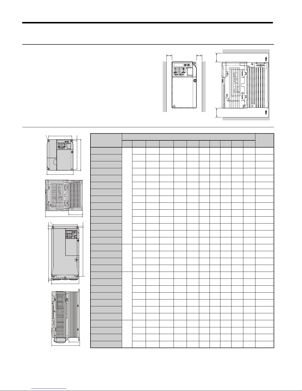
Installation Orientation and Spacing
Always install the drive in an upright position.
Leave space around the unit for proper cooling
as shown in the figure on the right.
Note: Several units can be installed closer
together than shown in the figure by
using “Side-by-Side” mounting. For
details please refer to the Technical
Manual.
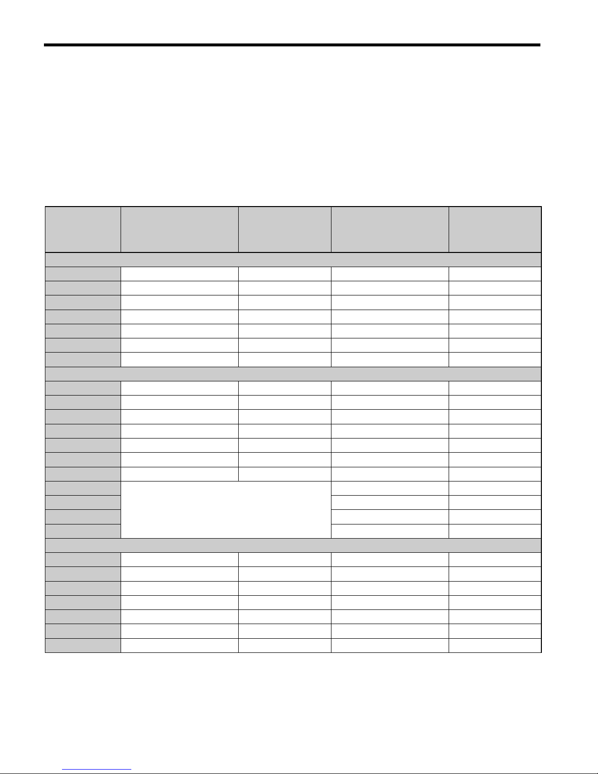
Dimensions
Model
CIMR-VC
Dimensions (mm)
Weight
(kg)
Fig. W H D W1 H1 H2 H3 H4 D1 d
BA0001B
A
68 128 76 56 118 5 - - 6.5 M4 0.6
BA0002B 68 128 76 56 118 5 - - 6.5 M4 0.6
BA0003B 68 128 118 56 118 5 - - 38.5 M4 1.0
BA0006B 108 128 137.5 96 118 5 - - 58 M4 1.7
BA0010B 108 128 154 96 118 5 - - 58 M4 1.8
BA0012B 140 128 163 128 118 5 - - 65 M4 2.4
BA0018B 170 128 180 158 118 5 - - 65 M4 3.0
2A0001B 68 128 76 56 118 5 - - 6.5 M4 0.6
2A0002B 68 128 76 56 118 5 - - 6.5 M4 0.6
2A0004B 68 128 108 56 118 5 - - 38.5 M4 0.9
2A0006B 68 128 128 56 118 5 - - 38.5 M4 1.1
2A0010B 108 128 129 96 118 5 - - 58 M4 1.7
2A0012B 108 128 137.5 96 118 5 - - 58 M4 1.7
2A0020B 140 128 143 128 118 5 - - 65 M4 2.4
2A0030F
B
140 254 140 122 248 6 13 6.2 55 M5 3.8
2A0040F 140 254 140 122 248 6 13 6.2 55 M5 3.8
2A0056F 180 290 163 160 284 8 15 6.2 75 M5 5.5
2A0069F 220 350 187 192 336 7 15 7.2 78 M6 9.2
4A0001B
A
108 128 81 96 118 5 - - 10 M4 1.0
4A0002B 108 128 99 96 118 5 - - 28 M4 1.2
4A0004B 108 128 137.5 96 118 5 - - 58 M4 1.7
4A0005B 108 128 154 96 118 5 - - 58 M4 1.7
4A0007B 108 128 154 96 118 5 - - 58 M4 1.7
4A0009B 108 128 154 96 118 5 - - 58 M4 1.7
4A0011B 140 128 143 128 118 5 - - 65 M4 2.4
4A0018F
B
140 254 140 122 248 6 13 6 55 M5 3.8
4A0023F 140 254 140 122 248 6 13 6.2 55 M5 3.8
4A0031F 180 290 143 160 284 8 15 6 55 M5 5.2
4A0038F 180 290 163 160 284 8 15 6 75 M5 5.5
30mm 30mm
100mm
100mm
Air
Air
B
IP20 / NEMA
Type
1
A
IP20 / Open
Chassis
D
D1
d
H
W1
W
H1
H2
D
D1
W
W1
H
H3
H4
H2
d
H1
Page 11

2 Mechanical Installation
YASKAWA Europe TOEP C710606 15C YASKAWA AC Drive - V1000 Quick Start Guide EN 9
ENGLISH
Model
CIMR-VC
Dimensions (mm)
Weight
(kg)
Fig. W H D W1 H1 H2 H3 H5 D1 d
2A0030A
C
140 247 140 122 248 6 13 13 55 M5 3.6
2A0040A 140 247 140 122 248 6 13 13 55 M5 3.6
2A0056A 180 285 163 160 284 8 15 15 75 M5 5.3
2A0069A 220 335 187 192 336 7 15 15 78 M6 8.7
4A0018A 140 247 140 122 248 6 13 13 55 M5 3.6
4A0023A 140 247 140 122 248 6 13 13 55 M5 3.6
4A0031A 180 285 143 160 284 8 15 15 55 M5 5.0
4A0038A 180 285 163 160 284 8 15 15 75 M5 5.3
W1
d
H1 H2
HH3
W
D
D1
C
IP00 / Open
Chassis
H5
Page 12
EN 10 YASKAWA Europe TOEP C710606 15C YASKAWA AC Drive - V1000 Quick Start Guide
3 Electrical Installation
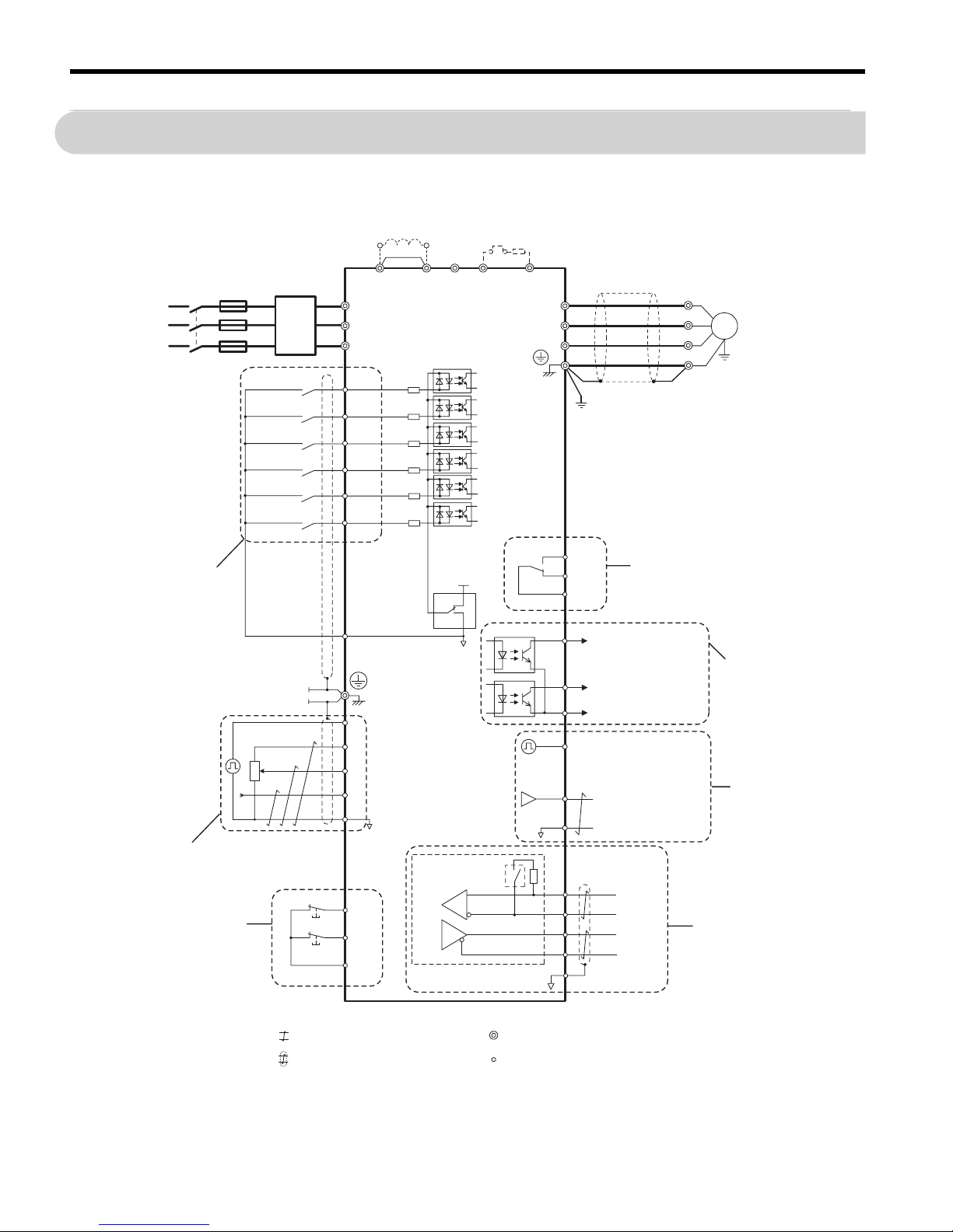
3 Electrical Installation
The figure below shows the main and control circuit wiring.
<1> Single-phase units do not have a T/L3 terminal.
Power
Supply
R/L1
S/L2
T/L3
S1
S2
S3
S4
S5
S6
㪄
B1+1+2 B2
L1
L2
L3
U/T1
V/T2
W/T3
24 V
0V
SINK
SOURCE
MA
P1
MB
MC
+24 V 8 mA
M
U
V
W
SC
P2
MP
AM
AC
PC
IG
R+
R−
S+
S−
H2
RP
+V
A1
A2
AC
2 kΩ
HC
H1
DC reactor
(option)
Filter
Fuses
Main
Switch
Forward/Stop
Reverse/Stop
External Fault
Fault Reset
Multi-speed 1
Multi-speed 2
Multi-function
digital inputs
(default setting)
Link
Thermal
relay
Braking
resistor
(opt)
V1000
Ground
Multi-function relay output
250 Vac / 30 Vdc (10 mA to 1A)
(default setting)
Fault
During run
Frequency agree
Photocoupler
common
Multi-function photocoupler output
48 Vdc, 2 to 50 mA
(default setting)
DIP
switch S3
Shielded ground
terminal
Pulse Input
(max. 32kHz)
Multi-function analog input 1
0 to 10 V (20 k
Ω)
Multi-function analog input 2
0 to 10 V (20 k
Ω) or
0/4 to 20 mA (250
Ω)
Analog input power supply
+10.5 Vdc, max. 20 mA
Multi- function pulse / analog inputs
(default: frequency reference)
Safe Disable
inputs
Monitor outputs
(default setting)
Analog output
0 to +10 Vdc (2mA)
(Output frequency)
Pulse train output
(max. 32 kHz)
(Output frequency)
Terminal resistance
(120
Ω, 1/2 W)
Memobus comm.
RS-485/422
max. 115 kBps
Shielded
Cable
Symbols:
Use twisted pair cables.
Use shielded twisted pair cables.
Indicates a main circuit terminal.
Indicates a control circuit terminal.
<1>
Page 13
3 Electrical Installation
YASKAWA Europe TOEP C710606 15C YASKAWA AC Drive - V1000 Quick Start Guide EN 11
ENGLISH
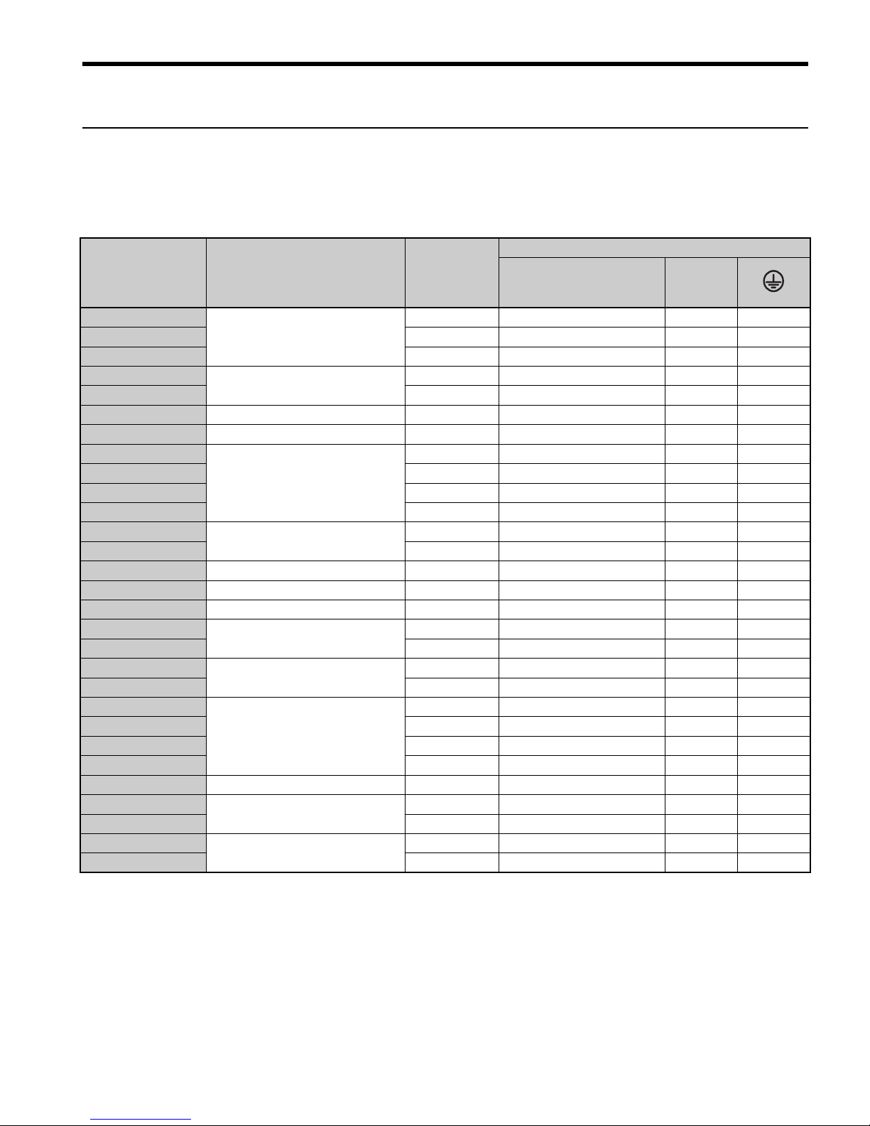
Wiring Specification
Main Circuit
Use the line filters listed up in the table below when wiring the main circuit. Make sure not
to exceed the given tightening torque values.
Model
CIMR-VC
EMC Filter [Schaffner]
Recom.
Motor cable
(mm²)
Main Circuit Terminal Sizes
R/L1,S/L2,T/L3,
U/T1,V/T2,W/T3, - ,
+1, +2
B1, B2
BA0001
FS5855-10-07
2.5 M3.5 M3.5 M3.5
BA0002 2.5 M3.5 M3.5 M3.5
BA0003 2.5 M3.5 M3.5 M3.5
BA0006
FS5855-20-07
2.5 M4 M4 M4
BA0010 4 M4 M4 M4
BA0012 FS5855-30-07 6 M4 M4 M4
BA0018 FS5855-40-07 10 M5 M5 M5
2A0001
FS5856-10-07
2.5 M3.5 M3.5 M3.5
2A0002 2.5 M3.5 M3.5 M3.5
2A0004 2.5 M3.5 M3.5 M3.5
2A0006 2.5 M3.5 M3.5 M3.5
2A0010
FS5856-20-07
2.5 M4 M4 M4
2A0012 4 M4 M4 M4
2A0020 FS5856-30-07 6 M4 M4 M4
2A0030 FS5973-35-07 10 M4 M4 M5
2A0040 FS5973-60-07 16 M4 M4 M5
2A0056
FS5973-100-07
25 M6 M5 M6
2A0069 35 M8 M5 M6
4A0001
FS5857-5-07
2.5 M4 M4 M4
4A0002 2.5 M4 M4 M4
4A0004
FS5857-10-07
2.5 M4 M4 M4
4A0005 2.5 M4 M4 M4
4A0007 2.5 M4 M4 M4
4A0009 2.5 M4 M4 M4
4A0011 FS5857-20-07 2.5 M4 M4 M4
4A0018
FS5972-35-07
6M4M4M5
4A0023 10 M4 M4 M5
4A0031
FS5972-60-07
10 M5 M5 M5
4A0038 16 M5 M5 M6
Page 14
3 Electrical Installation
EN 12 YASKAWA Europe TOEP C710606 15C YASKAWA AC Drive - V1000 Quick Start Guide
Input Fuse Selection
Branch circuit protection shall be provided by any of the following:
• Non-time delay Class J, T, or CC fuses sized at 300% of the drive input rating
Note: Unavailable models are A6T6 with 2A0002, A6T15 with 2A0004 or
4A0004, A6T20 with 4A0005, and A6T25 with 4A0007.
• Time delay Class J, T, or CC fuses sized at 175% of the drive input rating
• Time-delay Class RK5 fuses sized at 225% of the drive input rating
Model
CIMR-VC
Non-Time Delay
Class-T Fuse Type
(Manufacturer: Ferraz)
600 Vac, 200 kAIR
Fuse Ampere
Rating (A)
Fuse Type
(Manufacturer:
Bussmann)
500 Vac, 200 kAIR
Fuse Ampere
Rating (A)
Single-Phase 200 V Class
BA0001 A6T6 6 FWH-25A14F 25
BA0002 A6T10 10 FWH-25A14F 25
BA0003 A6T20 20 FWH-60B 60
BA0006 A6T40 40 FWH-80B 80
BA0010 A6T40 40 FWH-100B 100
BA0012 A6T50 50 FWH-125B 125
BA0018 A6T80 80 FWH-175B 175
Three-Phase 200 V Class
2A0001 A6T3 3 FWH-25A14F 25
2A0002 A6T6 6 FWH-25A14F 25
2A0004 A6T15 15 FWH-25A14F 25
2A0006 A6T20 20 FWH-25A14F 25
2A0010 A6T25 25 FWH-70B 70
2A0012 A6T30 30 FWH-70B 70
2A0020 A6T40 40 FWH-90B 90
2A0030
Not Available
FWH-100B 100
2A0040 FWH-200B 200
2A0056 FWH-200B 200
2A0069 FWH-200B 200
Three-Phase 400 V Class
4A0001 A6T3 3 FWH-40B 40
4A0002 A6T6 6 FWH-40B 40
4A0004 A6T15 15 FWH-50B 50
4A0005 A6T20 20 FWH-70B 70
4A0007 A6T25 25 FWH-70B 70
4A0009 A6T25 25 FWH-90B 90
4A0011 A6T30 30 FWH-90B 90
Page 15

3 Electrical Installation
YASKAWA Europe TOEP C710606 15C YASKAWA AC Drive - V1000 Quick Start Guide EN 13
ENGLISH
Control Circuit
The control terminal board is equipped with screwless terminals. Always use wires within
the specification listed below. For safe wiring it is recommended to use solid wires or flexible wires with ferrules. The stripping length respectively ferrule length should be 8 mm.
4A0018
Not Available
FWH-80B 80
4A0023 FWH-100B 100
4A0031 FWH-125B 125
4A0038 FWH-200B 200
Wire Type Wire size (mm2)
Solid 0.2 to 1.5
Flexible 0.2 to 1.0
Flexible with ferrule 0.25 to 0.5
Model
CIMR-VC
Non-Time Delay
Class-T Fuse Type
(Manufacturer: Ferraz)
600 Vac, 200 kAIR
Fuse Ampere
Rating (A)
Fuse Type
(Manufacturer:
Bussmann)
500 Vac, 200 kAIR
Fuse Ampere
Rating (A)
Page 16

3 Electrical Installation
EN 14 YASKAWA Europe TOEP C710606 15C YASKAWA AC Drive - V1000 Quick Start Guide
EMC Filter Installation
This drive has been tested in accordance with European standards EN61800-3. In order to
comply to the EMC standards, wire the main circuit as described below.
1. Install an appropriate EMC noise filter to the input side.See the list above or refer to the
Technical Manual for details.
2. Place the drive and EMC noise filter in the same enclosure.
3. Use braided shield cable for the drive and motor wiring
4. Remove any paint or dirt from ground connections for minimal ground impedance
5. Install an AC reactor at drives smaller than 1 kW for compliance with the
EN61000-3-2. Refer to the Technical Manual or contact your supplier for details
EMC Standards Compliant Wiring of Single and Three Phase Units
N
L1
E
N
L1
PE
R/L1S/L2 T/L3
U/T1 V/T2
W/T3
Wiring distance as
short as possible
Cable shield
grounding clamp
Drive
Braid shielded motor
cable
EMC
Filter
Grounding Surface
(remove any paint)
Metal plate
Panel or mounting wall
M
Grounding
Surface
(remove any
paint)
Ground shield at
motor side
L3
L2
L1
R/L1S/L2 T/L3
U/T1 V/T2
W/T3
E
L1
PE
R/L1S/L2 T/L3
U/T1 V/T2
W/T3
Wiring distance as
short as possible
Cable shield
grounding clamp
Drive
Braid shielded motor
cable
EMC
Filter
Grounding Surface
(remove any paint)
Metal plate
Panel or mounting wall
M
Grounding
Surface
(remove any
paint)
Ground shield at
motor side
L3
L2
Page 17

3 Electrical Installation
YASKAWA Europe TOEP C710606 15C YASKAWA AC Drive - V1000 Quick Start Guide EN 15
ENGLISH
Main and Control Circuit Wiring
Wiring the Main Circuit Input
Consider the following precautions for the main circuit input.
• Use fuses recommended in Main Circuit on page 11 only.
• When using residual current monitoring or detection devices (RCM/RCD), make sure the
devices are designed for use with AC drives (e.g. type B according to IEC 60755).
• If using a ground fault circuit breaker, make sure that it can detect both DC and high frequency current.
• If using an input switch is used, make sure that the switch does not operate not more than
once every 30 minutes.
• Use a DC reactor or AC reactor on the input side of the drive:
–To suppress harmonic current.
–To improve the power factor on the power supply side.
–When using an advancing capacitor switch.
–With a large capacity power supply transistor (over 600 kVA).
Wiring the Main Circuit Output
Consider the following precautions for the output circuit wiring.
• Do not connect any other load than a 3 phase motor to the drives output.
• Never connect a power source to the drives output.
• Never short or ground the output terminals.
• Do not use phase correction capacitors.
• If using a contactor between the drive and motor, it should never be operated when the
drive is outputting a voltage. Operating while there is voltage output can cause large peak
currents, thus tripping the over current detection or damage the drive.
Ground Connection
Take the following precautions when grounding the drive:
• The drive must always be connected to ground in accordance to the general technical standards and local regulations.
As the leakage current produced by the drive exceeds 3.5 mA, according to IEC 61800-51, at least one of the conditions below must be satisfied:
–The cross-section of the protective earthing conductor must be at least 10 mm
2
(Cu)
or 16 mm2 (Al).
–The power supply must be disconnected automatically in case of discontinuity of
the protective earthing conductor.
• Keep ground wires as short as possible.
Page 18

3 Electrical Installation
EN 16 YASKAWA Europe TOEP C710606 15C YASKAWA AC Drive - V1000 Quick Start Guide
• Always make sure the ground impedance is conformed to the requirements of local safety
and installation regulations.
• Never share the ground wire with other devices such as welding machines, etc.
• Do not loop the ground wire when using more than one drive.
Control Circuit Wiring Precautions
Consider the following precautions for wiring the control circuits.
• Separate control circuit wiring from main circuit wiring and other high-power lines.
• Separate wiring for control circuit terminals MA, MB, MC (contact output) from wiring
to other control circuit terminals.
• For external control power supply use a UL Listed Class 2 power supply.
• Use twisted-pair or shielded twisted-pair cables for control circuits to prevent operating
faults.
• Ground the cable shields with the maximum contact area of the shield and ground.
• Cable shields should be grounded on both cable ends.
• If flexible wires with ferrules are connected they might fit tightly into the terminals. To
disconnect them, grasp the wire end with a pair of pliers, release the terminal using a
straight-edge screw driver, turn the wire for about 45°, and pull it gently out of the terminal. For details, refer to the Technical Manual. Use this procedure for removing the wire
link between HC, H1 and H2 when the Safe Disable function is utilized.
Main Circuit Terminals
Terminal Ty pe Function
R/L1, S/L2, T/L3
Main circuit power
supply input
Connects line power to the drive.
Drives with single-phase 200 V input power have no T/L3 terminal.
U/T1, V/T2, W/T3 Drive output Connects to the motor.
B1, B2 Braking resistor For connecting a braking resistor or the braking resistor unit option.
+1, +2
DC reactor connection
Linked at shipment. Remove the link to install a DC choke.
+1, –
DC power supply
input
For connecting a DC power supply.
(2 terminals)
Ground Terminal
For 200 V class: Ground with 100 Ω or less
For 400 V class: Ground with 10 Ω or less
Page 19

3 Electrical Installation
YASKAWA Europe TOEP C710606 15C YASKAWA AC Drive - V1000 Quick Start Guide EN 17
ENGLISH
Control Circuit Terminals
The figure below shows the control circuit terminal arrangement. The drive is equipped with
screwless terminals.
There are three DIP switches, S1 to S3, located on the terminal board
SW1 Switches analog input A2 between voltage and current input
SW2 Enables or disables the internal RS422/485 comm. port terminal resistance.
SW3
Used to select sourcing (PNP)/sinking (NPN, default) mode for the digital inputs (PNP requires
external 24 Vdc power supply)
S1 S2 S3 S4 S5 S6 SC HC H1 H2 RP
R+
R- S+ S-
IG
P1 P2 PC A1 A2 +V AC AM AC MP
MA MB MC
S1
S2
S3
Use a straght-edge screwdriver
with a blade width of max 2.5 mm
and a thickness of max 0.6 mm to
release the terminals
Page 20

3 Electrical Installation
EN 18 YASKAWA Europe TOEP C710606 15C YASKAWA AC Drive - V1000 Quick Start Guide
Control Circuit Terminal Functions
NOTICE! The terminals HC, H1, H2 are used for the Safe Disable function which cuts the
output voltage in less than 1 ms if at least one of the inputs H1 or H2 is opened. It is
designed in accordance with the EN954-1, safety category 3 and EN61508, SIL2. It
and can be utilized to perform a safe stop as defined by the EN60204-1, stop
category 0. Do not remove the wire link between HC, H1, or H2 unless the Safe
Disable function is used. Refer to the Technical Manual when using this function.
NOTICE! The wiring length to the terminals HC, H1 and H2 should not exceed 30 m.
Type No. Terminal Name (Signal) Function (Signal Level), Default Setting
MultiFunction
Digital
Inputs
S1
toS6Multi-function digital input 1 to 6
Photocoupler inputs, 24 Vdc, 8 mA
Note: Drive preset to sinking mode (NPN). When using
source mode, set DIP switch S3 to “SOURCE” and use an
external 24 Vdc (±10%) power supply.
SC Multi-function input common Sequence common
MultiFunction
Analog/
Pulse
Inputs
RP Pulse train input
Response frequency: 0.5 to 32 kHz, Duty: 30 to 70%, High:
3.5 to 13.2 V, Low: 0.0 to 0.8 V, input impedance: 3 kΩ)
+V Analog input power supply +10.5 V (max allowable current 20 mA)
A1 Multi-function analog input 1
0 to +10 Vdc (20 kΩ) resolution 1/1000
0/4 to 20 mA (250 Ω) resolution: 1/500 (A2 only)
A2 Multi-function analog input 2
AC Frequency reference common 0 V
Safe
Disable
Inputs
HC Safe Disable Input common +24 V (max 10 mA allowed)
H1 Safe Disable Input 1 One or both open: Drive output disabled (time from input
open to drive output switch off is less than 1 ms)
Both Closed: Normal operation
H2 Safe Disable Input 2
MultiFunction
Relay
Output
MA N.O. (fault)
Digital relay output
30 Vdc, 10 mA to 1 A
250 Vac, 10 mA to 1 A
MB N.C. output (fault)
MC Digital output common
MultiFunction
PHC
Output
P1 Photocoupler output 1
Digital photocoupler output
48 Vdc, 2 to 50 mA
P2 Photocoupler output 2
PC Photocoupler output common
Monitor
Output
MP Pulse train output 32 kHz (max)
AM Analog monitor output 0 to 10 Vdc (2 mA or less), Resolution: 1/1000 (10 bit)
AC Monitor common 0 V
MEMOBUS/
Communication
R+ Communications input (+)
MEMOBUS/Modbus communication.:
RS-485 or RS-422, 115.2 kbps (max)
R– Communications input (–)
S+ Communications output (+)
S- Communications output (–)
Page 21

ENGLISH
4 Keypad Operation
YASKAWA Europe TOEP C710606 15C YASKAWA AC Drive - V1000 Quick Start Guide EN 19
4 Keypad Operation
LED Operator and Keys
The LED operator is used to program the drive, to start/
stop it, and to display fault information. The LEDs indicate the drive status.
Keys and Functions
Display Name Function
Data Display Area Displays the frequency reference, parameter number, etc.
ESC Key Returns to the previous menu.
RESET Key
Moves the cursor to the right.
Resets a fault.
RUN Key
Starts the drive in the LOCAL mode. The Run LED
• is on, when the drive is operating the motor.
• flashes during deceleration to stop or when the frequency reference is 0.
• flashes quickly the drive is disabled by a DI, the drive was stopped using a fast
stop DI or a run command was active during power up.
Up Arrow Key Scrolls up to select parameter numbers, setting values, etc.
Down Arrow Key Scrolls down to select parameter numbers, setting values, etc.
STOP Key Stops the drive.
ENTER Key Selects modes, parameters and is used to store settings.
LO/RE Selection
Key
Switches drive control between the operator (LOCAL) and the control circuit
terminals (REMOTE). The LED is on when the drive is in the LOCAL mode
(operation from keypad).
ALM LED Light
Flashing: The drive is in an alarm state.
On: The drive is in a fault state and the output is stopped.
REV LED Light
On: The motor rotation direction is reverse.
Off: The motor rotation direction is forward.
DRV LED Light
On: The drive is ready to operate the motor.
Off: The drive is in the Verify, Setup, Parameter Setting or Auto tuning mode.
FOUT LED Light
On: The output frequency is displayed on the data screen.
Off: Anything else than the output frequency is displayed on the data screen.
STOP
RUN
STOP
ALM
REV
DRV
FOUT
Page 22

4 Keypad Operation
EN 20 YASKAWA Europe TOEP C710606 15C YASKAWA AC Drive - V1000 Quick Start Guide
Menu Structure and Modes
The following illustration explains the operator keypad menu structure.
XXXX
XX
XX
XX
XX
XX
XX
XX
XX
XX
XX
XX
DRV LED is off.
The motor can not be started.
:
:
:
:
Key operation description
Turn the power on (DRV lights)
Forward Selection Reverse Selection
Output Frequency
Output Current
Output Voltage
Monitor Display
Verify Menu
Setup Mode
Parameter Setting Mode
Auto-Tuning
DRV LED is on.
A Run command will start the motor.
The Monitor Displays are used to
read out drive data like terminal
status, output frequency, fault
information etc.
The Verify Menu lists up all
parameters which are unequal to
the default setting.
The Setup Mode can be used to
set up a minimum list of
parameters necessary to run the
application.
In the Parameter Setting Mode all
drive parameters can be set up.
Auto-Tuning measures the motor
data for optimal performance of
the drive/motor combination.
Page 23

ENGLISH
5 Start Up
YASKAWA Europe TOEP C710606 15C YASKAWA AC Drive - V1000 Quick Start Guide EN 21
5Start Up
Drive Setup Procedure
The illustration below shows the basic setup procedure. Each step is explained more detailed
on the following pages.
Install and wire the drive as explained.
Turn the power on.
Set the control mode.
Set/check the basic parameters:
* b1-01, b1-02 for frequency reference and RUN command source
* H1-xx, H2-xx, H3-xx, H4-xx, H6-xx to configure the I/Os
* Frequency reference values
* C1-xx, C2-xx for Acceleration/Deceleration times and S-curves
Run the motor without load, check the operation and verify, if the
upper controller (e.g. PLC,...) commands to the drive work as
desired.
Connect the load, run the motor and check the operation
Fine tune and set application parameters (e.g. PID,...) if necessary.
Final check the operation and verify the settings.
Drive is ready to run the application
START
Perform Auto-Tuning or set the motor data manually.
Initialize the drive if necessary using parameter A1-01.
Select Normal / Heavy Duty
Page 24

5 Start Up
EN 22 YASKAWA Europe TOEP C710606 15C YASKAWA AC Drive - V1000 Quick Start Guide
Power On
Before turning on the power supply,
• Make sure all wires are connected properly.
• Make sure no screws, loose wire ends or tools are left in the drive.
• After turning the power on, the drive mode display should appear and no fault or alarm
should be displayed.
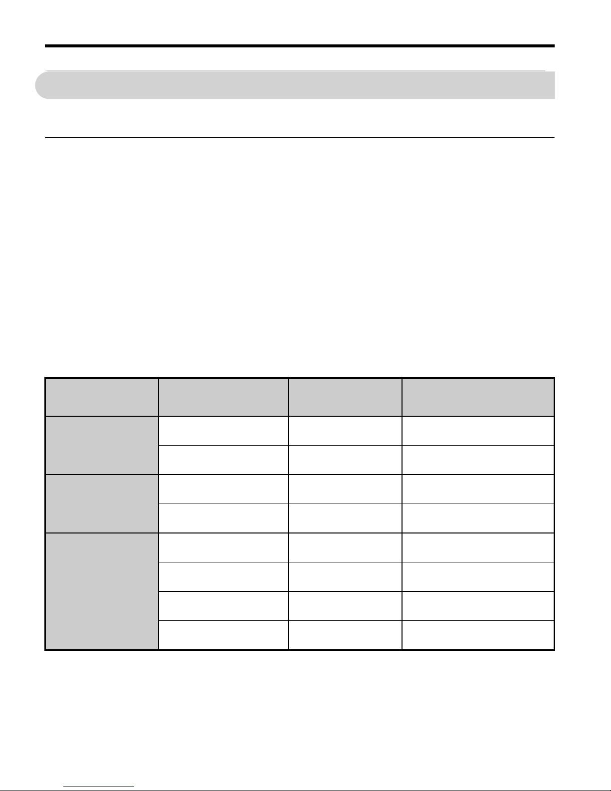
Control Mode Selection (A1-02)
There are three control modes available. Select the control mode that best suits the application the drive will control.
Normal / Heavy Duty Selection (C6-01)
The drive supports two ratings, Normal Duty and Heavy Duty. Both have different output
current ratings (refer to the catalog or Technical Manual). Set the Duty mode in accordance
with the application.
Control Mode Parameter Main Applications
V/f Control
A1-02 = 0
(default)
• General variable speed applications, particularly useful for running multiple motors from a single drive
• When replacing a drive in which parameter settings are unknown
Open Loop
Vector Control (OLV)
A1-02 = 2
• General variable speed applications
• Applications requiring high precision, high speed control
PM Open Loop
Vector Control
A1-02 = 5
• Derated torque-load applications employing permanent magnet motors
(SPM, IPM) and energy savings.
Mode Heavy Duty Rating (HD) Normal Duty Rating (ND)
C6-01 0 1
Application
Applications with a constant torque like
extruders, conveyors and cranes. High
overload capability might be needed.
Applications where the torque increases with
the speed like fans or pumps. High overload
tolerance is normally not needed.
Overload capability (OL2) 150% of drive rated current for 60 s 120% of drive rated current for 60 s
L3-02 Stall Prevention dur-
ing Acceleration
150% 120%
L3-06 Stall Prevention during Run
150% 120%
Default carrier frequency 8 kHz Swing PWM
Page 25

5 Start Up
YASKAWA Europe TOEP C710606 15C YASKAWA AC Drive - V1000 Quick Start Guide EN 23
ENGLISH
Auto-Tuning (T1-)
Auto-Tuning automatically sets up the motor data relevant drive parameters. Three different
modes are supported
For Auto-Tuning enter the Auto-Tuning menu and perform the steps shown in the figure
below. The number of name plate data to be entered depends on the selected type of AutoTuning. This example shows Rotational Auto-Tuning.
If Auto-Tuning can not be performed for some reason (no-load operation impossible etc.),
then set up the maximum frequency and voltage in the E1- parameters and enter the
motor data manually into the E2- parameters.
NOTICE! The Safe Disable inputs must be closed during Auto-Tuning.
Tuning Mode Parameter
Control
Mode
Description
Rotational
Auto-Tuning
T1-01 = 0 OLV
Perform when setting the drive to operate in Open Loop
Vector control. The motor must be able to rotate without
load during the tuning process in order to achieve a high
accuracy.
Terminal resistance
tuning
T1-01 = 2
OLV, V/f
control
Perform in V/f control if the motor cable is long or if the
cable has been changed.
Rotational
Auto-Tuning
for Energy Saving
T1-01 = 3 V/f control
Perform when using Energy Saving or Speed Search.The
motor must be able to rotate without load in order to achieve
a high tuning accuracy.
CAUTION
Never touch the motor until the Auto-Tuning is finished. Even thought the motor may not be
rotating when Auto-Tuning, voltage is still applied to the motor during the tuning process.
Enter the Auto-
Tuning Mode
Select the tuning
method
Set up all name
plate data
The tuning start
display appears
During the tuning the
display flashes
After successful tuning
“End” is displayed
Drive mode
display
Page 26
5 Start Up
EN 24 YASKAWA Europe TOEP C710606 15C YASKAWA AC Drive - V1000 Quick Start Guide
Reference and Run Source
The drive has a LOCAL and a REMOTE mode.
If the drive is operated in the REMOTE mode, make sure that the correct sources for the frequency reference and run command are set in parameters b1-01/02 and that the drive is in
the REMOTE mode.
The LED in the LO/RE key indicates where the Run command is input from.
I/O Setup
Multi-Function Digital Inputs (H1-)
The function of each digital input can be assigned in the H1- parameters. The default setting functions can be seen in the connection diagram on page 10.
Multi-Function Digital Outputs (H2-)
The function of each digital output can be assigned in the H2- parameters. The default
setting functions can be seen in the connection diagram on page 10. The setting value of
these parameters consist of 3 digits, where the middle and right digit set the function and the
left digit sets the output characteristics (0: Output as selected; 1: Inverse output).
Multi-Function Analog Inputs (H3-)
The function of each analog input can be assigned in the H3- parameters. The default
setting of both inputs is “Frequency bias”. Input A1 is set for 0 to 10V input and A2 is set for
4-20 mA input. The addition of both input values builds the frequency reference.
NOTICE! If the input signal level of input A2 is switched between voltage and current, make
sure that DIP switch S1 is in the correct position and parameter H3-09 is set up
correctly.
Monitor Output (H4-)
Use the H4- parameters to set up the output value of the analog monitor output and to
adjust the output voltage levels. The default monitor value setting is “Output frequency”.
Status Description
LOCAL The Run/ Stop command and the frequency reference are entered at the operator keypad.
REMOTE
The Run command source entered in parameter b1-02 and the frequency reference
source entered in parameter b1-01 are used.
LO/RE LED Description
ON Run command is issued from operator.
OFF Run command is issued from a different source than the operator.
Page 27

5 Start Up
YASKAWA Europe TOEP C710606 15C YASKAWA AC Drive - V1000 Quick Start Guide EN 25
ENGLISH
Frequency Reference and Acceleration/ Deceleration Times
Frequency Reference Setup(b1-01)
Set parameter b1-01 according to the frequency reference used.
Acceleration/ Deceleration Times and S-Curves
There are four sets of acceleration and deceleration times which can be set in the C1-
parameters. The default activated accel/decel times are C1-01/02. Adjust these times to the
appropriate values required by the application. If necessary S-curves can be activated in the
C2- parameters for softer accel/decel start and end.
Test Run
Perform the following steps to start up the machine after all parameter settings have been
done.
1. Run the motor without load and check if all input, outputs and the sequence work as
desired.
2. Connect the load to the motor.
3. Run the motor with load and make sure that there is no vibrations, hunting or motor
stalling occurs.
After taking the steps listed above, the drive should be ready to run the application and perform the basic functions. For special setups like PID control etc. refer to the Technical Manual.
b1-01 Reference source Frequency reference input
0 Operator keypad
Set the frequency references in the d1- parameters and used digital inputs to
switch over between different reference values.
1 Analog input Apply the frequency reference signal to terminal A1 or A2.
2 Serial Comm. Serial Communications using the RS422/485 port
3 Option Board Communications option card
4 Pulse input Set the frequency reference at terminal RP using a pulse train signal.
Page 28

EN 26 YASKAWA Europe TOEP C710606 15C YASKAWA AC Drive - V1000 Quick Start Guide
6 Parameter Table
6 Parameter Table
This parameter table shows the most important parameters. Default settings are bold
type. Refer to the Technical Manual for a
complete list of parameters.
Par. Name Description
Initialization Parameters
A1-01
Access
Level
Selection
Selects which parameters are
accessible via the digital operator.
0:Operation only
1:User Parameters
2:Advanced Access Level
A1-02
Control
Method
Selection
Selects the Control Method of the
drive.
0: V/f Control
2: Open Loop Vector (OLV)
5: PM Open Loop Vector (PM)
Note: Not initialized with A1-03!
A1-03
Initialize
Parameters
Resets all parameters to default.
(returns to 0 after initialization)
0:No Initialize
1110: User Initialize (The user
must first set user parameter values
and then store them using parameter o2-03)
2220: 2-Wire Initialization
3330: 3-Wire Initialization
Operation Mode Selection
b1-01
Frequency
Reference
Selection
0:Operator - d1- values
1:Analog input A1 or A2
2:Serial Com - RS-422/485
3:Option board
4:Pulse Input (Terminal RP)
b1-02
Run
Command
Selection
0:Operator - RUN and STOP keys
1:Terminals - Digital Inputs
2:Serial Com - RS-422/485
3:Option board connected
b1-03
Stopping
Method
Selection
Selects the stopping method when
the run command is removed.
0:Ramp to Stop
1:Coast to Stop
2:DC Injection Braking to Stop
3:Coast with Timer (a new run
command is ignored if received
before the timer expires)
b1-04
Reverse
Operation
Selection
0:Reverse enabled
1:Reverse prohibited
b1-14
Phase Order
Selection
Switches the output phase order.
0:Standard
1:Switch phase order
DC Injection Braking
b2-01
DC
Injection
Braking
Start
Frequency
Sets the frequency at which DC
Injection Braking starts when
Ramp to Stop (b1-03 = 0) is
selected. If b2-01< E1-09, DC
Injection Braking starts at E1-09.
b2-02
DC
Injection
Braking
Current
Sets the DC Injection Braking current as a percentage of the drive
rated current.
In OLV the DC excitation current is
determined by E2-03.
b2-03
DC Inj.
Braking
Time/DC
Excitation
Time at
Start
Sets the time of DC Injection Braking at start in units of 0.01 seconds.
Disabled when set to 0.00 seconds.
b2-04
DC Inj.
Braking
Time at
Stop
Sets the DC Injection Braking time
at stop. Disabled when set to 0.00
seconds.
Acceleration/ Deceleration
C1-01
Accel
Time 1
Sets the acceleration time 1 from 0
to the max. output frequency.
C1-02
Decel
Time 1
Sets the deceleration time 1 from
the max. output frequency to 0.
Par. Name Description
Page 29

6 Parameter Table
YASKAWA Europe TOEP C710606 15C YASKAWA AC Drive - V1000 Quick Start Guide EN 27
ENGLISH
Par. Name Description
C1-03
to
C1-08
Accel/Decel
Times 2 to 4
Set the accel/decel times 2 to 4 (set
like C1-01/02).
C2-01 S-Curve 1 S-curve at acceleration start.
C2-02 S-Curve 2 S-curve at acceleration end.
C2-03 S-Curve 3 S-curve at deceleration start.
C2-04 S-Curve 4 S-curve at deceleration end.
Slip Compensation
C3-01
Slip Compensation
Gain
• Increase if the speed is lower than
the frequency reference.
• Decrease if the speed is higher
than the frequency reference.
C3-02
Slip Compensation
Delay Time
• Decrease the setting when the slip
compensation is too slow.
• Increase the setting when the
speed is not stable.
Torque Compensation
C4-01
Torque Compensation
Gain
• Increase this setting when the
torque response is slow.
• Decrease this setting when speed/
torque oscillations occur.
C4-02
Torque Compensation
Delay Time
• Increase this setting when speed /
torque oscillations occur.
• Decrease the setting when the
torque response is too slow.
Duty Mode and Carrier Frequency
C6-01
Normal/
Heavy Duty
Selection
0: Heavy Duty (HD)
Constant torque applications
1:Normal Duty (ND)
Variable torque application
C6-02
Carrier
Frequency
Selection
1:2.0 kHz
2:5.0 kHz
3:8.0 kHz
4:10.0 kHz
5:12.5 kHz
6:15.0 kHz
7 to A: Swing PWM1 to 4
F: User defined
Frequency References
d1-01
to
d1-16
Frequency
Reference
1 to 16
Set the multi-speed references 1 to
16.
d1-17 Jog Speed Jog speed
V/f Pattern
E1-01
Input
Voltage
Setting
Input Voltage
E1-04
Max. Output
Freq.
For a linear V/f characteristics, set
the same values for E1-07 and E1-
09. In this case, the setting for E108 will be disregarded.
Ensure that the four frequencies are
set according to these rules or
OPE10 fault will occur:
E1-04 ≥ E1-06 ≥ E1-07 ≥ E1-09
E1-05
Max. Output
Voltage
E1-06
Base
Frequency
E1-07
Middle Output Freq.
E1-08
Mid. Output
Vo l t a g e
E1-09
Min. Output
Freq.
E1-10
Min. Output
Vo l t a g e
E1-13
Base
Vo l t a g e
Motor Data
E2-01
Motor Rated
Current
Automatically set during Auto-Tuning.
E2-02
Motor Rated
Slip
Motor rated slip in hertz (Hz).
Automatically set by Rotational
Auto-Tuning.
E2-03
Motor
No-Load
Current
Magnetizing current in Ampere.
Automatically set by Rotational
Auto-Tuning.
E2-04 Motor Poles
Number of motor poles.
Automatically set by Auto-Tuning.
E2-05
Motor Lineto-Line
Resistance
Sets the phase-to-phase motor
resistance in ohms.
Automatically set by Auto-Tuning.
E2-06
Motor Leakage Inductance
Sets the voltage drop due to motor
leakage inductance as a percentage
of motor rated voltage.
Automatically set by Auto-Tuning.
Par. Name Description
(E1-04)(E1-06)(E1-07)(E1-09)
(E1-10)
(E1-08)
(E1-05)
(E1-13)
Output voltage
Output frequency
Page 30
6 Parameter Table
EN 28 YASKAWA Europe TOEP C710606 15C YASKAWA AC Drive - V1000 Quick Start Guide
Digital Input Settings
H1-01
to
H1-06
DI S1 to S6
Function
Selection
Selects the function of terminals S1
to S6.
Major functions are listed at the end of the table.
Digital Output Settings
H2-01
DO MA/MB
Function
Set the function for the relay output
MA-MB-MC.
H2-02
DO P1
Function
Sets the function for the photocoupler output P1.
H2-03
DO P2
Function
Sets the function for the photocoupler output P2.
Major functions are listed at the end of the table.
Analog Input Setting
H3-01
A1 Signal
Level Sel.
0:0 to +10 V (neg. input is zeroed)
1:0 to +10 V (bipolar input)
H3-02
A1
Function Sel.
Assign a function to terminal A1.
H3-03 A1 Gain
Sets the input value in % at 10 V
analog input.
H3-04 A1 Bias
Sets the input value in % at 0 V
analog input.
H3-09
A2 Signal
Level Selection
0:0 to +10 V (neg. input is zeroed)
1:0 to +10 V (bipolar input)
2:4 to 20 mA (9 bit input)
3:0 to 20 mA
H3-10
A2
Function Sel.
Assign a function to terminal A2.
H3-11 A2 Gain
Sets the input value in % at
10 V/20 mA analog input.
H3-12 A2 Bias
Sets the input value in % at
0 V/0 mA/4 mA analog input.
Analog Input Setting
H4-01AMMonitor
Selection
Enter value equal to U1-
monitor values. Example: Enter
“103” for U1-03.
H4-02 AM Gain
Sets terminal AM output voltage
equal to 100% monitor value.
H4-02 AM Bias
Sets terminal AM output voltage
equal to 0% monitor value.
Par. Name Description
Pulse Input Setting (Free. ref. input)
H6-02
RP Input
Scaling
Sets the number of pulses (in Hz)
that is equal to 100% input value.
H6-03
Pulse Train
Input Gain
Sets the input value in % at pulse
input with H6-02 frequency.
H6-04
Pulse Train
Input Bias
Sets the input value in % at 0 Hz
pulse input frequency.
Pulse Output Setting
H6-06
MP Monitor
Sel.
Enter value equal to U-
monitor values. Example: Enter
“102” for U1-02.
H6-07
MP Monitor
Scaling
Sets the number of output pulses
when the monitor is 100% (in Hz).
Motor Overheat Protection
L1-01
Motor Overload Prot.
Sel.
Sets the motor overload protection.
0:Disabled
1:Standard fan cooled motor
2:Standard blower cooled motor
3:Vector motor
L1-02
Motor Overload Prot.
Time
Sets the motor overload protection
time in min. Normally no change is
necessary.
Stall Prevention
L3-01
Stall
Prevention
Selection
during
Acceleration
0:Disabled - Motor accelerates at
active acceleration rate and may
stall with too heavy load or too
short accel time.
1:General Purpose - Hold
acceleration when current is
above L3-02.
2:Intelligent - Acceleration in the
shortest possible time.
L3-02
Stall Prev.
Level during Accel.
Sets the current level for stall prevention during acceleration.
L3-04
Stall Prev.
Selection
during
Decel.
0:Disabled - Deceleration as set.
OV might occur.
1:General Purpose - Deceleration
is hold if DC bus voltage rises
high.
L3-05
Stall Prev.
Selection
during Run
0:Disabled - Motor stall or
overload might occur.
1:Decel Time 1 - Reduce speed
using C1-02.
Par. Name Description
Page 31

6 Parameter Table
YASKAWA Europe TOEP C710606 15C YASKAWA AC Drive - V1000 Quick Start Guide EN 29
ENGLISH
L3-06
Stall Prev.
Level during Run
Sets the current level at which stall
prevention during run starts to
operate.
Auto-Tuning
T1-01
Auto-Tuning Mode
Selection
0:Rotational Auto-Tuning
2: Terminal resistance only
3: Rotational Auto-Tuning for
Energy Saving
T1-02 Rated Power Sets the motor rated power (kW).
T1-03
Rated
Voltage
Sets the motor rated voltage (V).
T1-04
Rated
Current
Sets the motor rated current (A).
T1-05
Base
Frequency
Sets the motor base frequency
(Hz).
T1-06 Motor Poles Sets the number of motor poles.
T1-07 Base Speed Sets the motor base speed (RPM).
T1-11
Motor Iron
Loss
Iron loss for determining the
Energy Saving coefficient.
If unknown leave it on default.
Monitor Description
U1-01 Frequency Reference (Hz)
U1-02 Output Frequency (Hz)
U1-03 Output Current (A)
U1-05 Motor Speed (Hz)
U1-06 Output Voltage Reference (Vac)
U1-07 DC Bus Voltage (Vdc)
U1-08 Output Power (kW)
U1-09 Torque Reference (% of motor rated torque)
Par. Name Description
U1-10
Input Terminal Status
U1-11
Output Terminal Status
U1-12
Drive Status
U1-13 Terminal A1 input level
U1-14 Terminal A2 input level
U1-16
Soft Starter Output (freq after accel/decel
ramps)
U1-18 OPE Fault Parameter
U1-24 Pulse Input frequency
Monitor Description
1: Digital input 1
(terminal S1 enabled)
1: Digital input 2
(terminal S2 enabled)
1: Digital input 3
(terminal S3 enabled)
1: Digital input 4
(terminal S4 enabled)
1: Digital input 5
(terminal S5 enabled)
1: Digital input6
(terminal S6 enabled)
: ON : OFF
Reserved
1: Relay Output
(terminal MA-MC closed
MB-MC open)
1: Open Collector Output 1
(terminal P1) enabled
1: Open collector Output 2
(terminal P2) enabled
: ON
Reserved
: OFF
1: During run
1: During zero-speed
1: During REV
1: During fault reset
signal input
1: During speed agree
1: Drive ready
1: During alarm detection
1: During fault detection
Page 32

6 Parameter Table
EN 30 YASKAWA Europe TOEP C710606 15C YASKAWA AC Drive - V1000 Quick Start Guide
Fault Trace
U2-01 Current Fault
U2-02 Previous Fault
U2-03 Frequency Reference at Previous Fault
U2-04 Output Frequency at Previous Fault
U2-05 Output Current at Previous Fault
U2-06 Motor Speed at Previous Fault
U2-07 Output Voltage at Previous Fault
U2-08 DC Bus Voltage at Previous Fault
U2-09 Output Power at Previous Fault
U2-10 Torque Reference at Previous Fault
U2-11 Input Terminal Status at Previous Fault
U2-12 Output Terminal Status at Previous Fault
U2-13 Drive Operation Status at Previous Fault
U2-14 Cumulative Operation Time at Previous Fault
U2-15 Soft-Starter Speed Reference at Previous Fault
U2-16 Motor q-Axis Current at Previous Fault
U2-17 Motor d-Axis Current at Previous Fault
Fault History
U3-01
to
U3-04
Lists the most recent fault that occurred
through the fourth most recent fault.
U3-05
to
U3-08
Accumulated operation time at the most recent
fault through the fourth most recent fault.
U3-09 to
U3-14
Lists the fifth most recent fault that occurred
through the tenth most recent fault.
U3-15 to
U3-20
Accumulated operation time at fifth most
recent fault through the tenth most recent
fault.
* The following faults are not recorded in the error log:
CPF00, 01, 02, 03, UV1, and UV2.
Monitor Description DI/DO
Sel.
Description
Digital Input Function Selections
3 Multi-step speed reference 1
4 Multi-step speed reference 2
5 Multi-step speed reference 3
6
Jog frequency command (higher priority than
multi-step speed reference)
7 Accel/decel time selection 1
F Not used (Set when a terminal is not used)
14 Fault reset (Reset when turned ON)
20 to 2F
External fault; Input mode: N.O. contact /
N.C. contact, Detection mode: Normal/during
operation
Digital Output Function Selections
0
During Run (ON: run command is ON or voltage is being output)
1 Zero Speed
2 Speed Agree
6 Drive Ready
EFault
F Not used
10 Minor fault (Alarm) (ON: Alarm displayed)
Page 33

ENGLISH
7 Troubleshooting
YASKAWA Europe TOEP C710606 15C YASKAWA AC Drive - V1000 Quick Start Guide EN 31
7 Troubleshooting
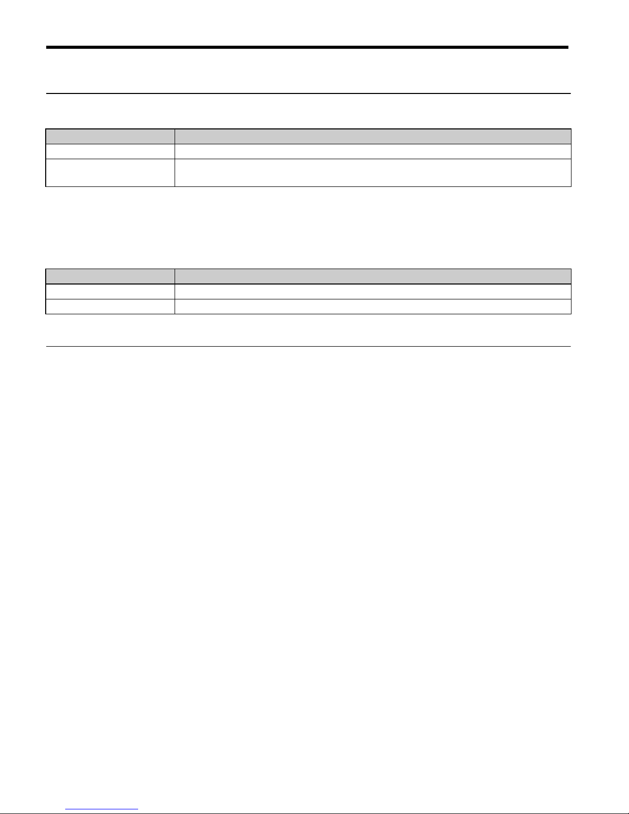
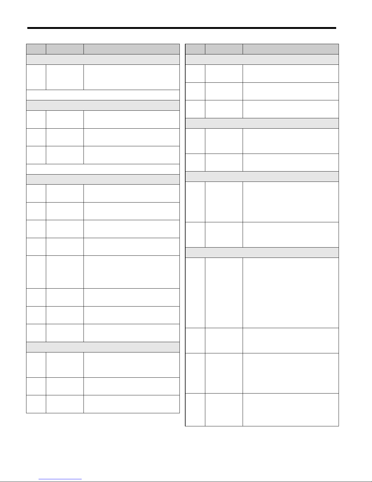
General Fault and Alarms
Faults and alarms indicate problems in the drive or in the machine.
An alarm is indicated by a code on the data display and the flashing ALM LED. The drive
output is not necessarily switched off.
A fault is indicated by a code on the data display and the ALM LED is on. The drive output
is always switched off immediately and the motor coast to stop.
To remove an alarm or reset a fault, trace the cause, remove it and reset the drive by pushing
the Reset key on the operator or cycling the power supply.
This lists up the most important alarms and faults only. Please refer to the Technical Manual
for a complete list.
LED Display AL FLT Cause Corrective Action
Base Block
The software base block function is assigned
to one of the digital inputs and the input is
off. The drive does not accept Run commands.
• Check the digital inputs function selection.
• Check the upper controller sequence.
Control Fault
The torque limit was reached during deceleration for longer than 3 sec. when in Open
Loop Vector control
• The load inertia is too big.
• The torque limit is too low.
• The motor parameters are wrong.
• Check the load.
• Set the torque limit to the most appropriate
setting (L7-01 through L7-04).
• Check the motor parameters.
Control Circuit
Fault
There is a problem in the drive’s control circuit.
• Cycle the drive power supply.
• Initialize the drive.
• Replace the drive if the fault occurs again.
Control Circuit
Fault
There is no terminal board connected to the
control board.
• Check if the terminal board is installed
properly.
• Uninstall and Reapply the terminal board.
• Change the drive.
Cannot Reset
Fault reset was input when a Run command
was active.
Turn off the Run command and reset the
drive.
Option
External Fault
An external fault was tripped by the upper
controller via an option card.
• Remove the fault cause, reset the fault and
restart the drive.
• Check the upper controller program.
External Fault
A forward and reverse command were input
simultaneously for longer than 500 ms. This
alarm stops a running motor.
• Check the sequence and make sure that the
forward and reverse input are not set at the
same time.
to
Page 34

7 Troubleshooting
EN 32 YASKAWA Europe TOEP C710606 15C YASKAWA AC Drive - V1000 Quick Start Guide
External Faults
• An external fault was triggered by an external device via one of the digital inputs S1
to S6.
• The digital inputs are set up incorrectly.
• Find out why the device tripped the EF.
Remove the cause and reset the fault.
• Check the functions assigned to the digital
inputs.
Ground Fault
• Ground leakage current has exceeded 50%
of the drives rated output current.
• Cable or motor insulation is broken.
• Excessive stray capacitance at drive output.
• Check the output wiring and the motor for
short circuits or broken insulation. Replace
any broken parts.
• Reduce the carrier frequency.
Safe Disable
Both Safe Disable inputs are open. The drive
output is safely disabled and the motor can
not be started.
• Check why the upper controller’s safety
device disabled the drive. Remove the
cause and restart.
• Check the wiring.
• If the Safe Disable function is not utilized
for EN60204-1, stop cat. 0 or for disabling
the drive, the terminals HC, H1, H2 must
be linked.
Safe Disable
Fault
Drive output is disabled while only one of
the Safe Disable inputs is open. (normally
both input signals H1 and H2 should be
open)
• One channel is internally broken and does
not switch off, even if the external signal is
removed.
• Only one channel is switched off by the
upper controller.
• Check the wiring from the upper controller
and make sure that both signals are set correctly by the controller.
• If the signals are set correctly and the
alarm does not disappear, replace the drive.
Output Phase
Loss
Output cable is disconnected or the motor
winding is damaged.
Loose wires at the drive output.
Motor is too small (less than 5% of drive
current).
• Check the motor wiring.
• Make sure all terminal screws in the drive
and motor are properly tightened.
• Check the motor and drive capacity.
Overcurrent
Short circuit or ground fault on the drive output side
The load is too heavy.
The accel./decel. times are too short.
Wrong motor data or V/f pattern settings.
A magnetic contactor was switched at the
output.
• Check the output wiring and the motor for
short circuits or broken insulation. Replace
the broken parts.
• Check the machine for damages (gears,
etc.) and repair any broken parts.
• Check the drive parameter settings.
• Check the output contactor sequence.
Heatsink
Overheat
Surrounding temperature is too high.
The cooling fan has stopped.
The heatsink is dirty.
The airflow to the heatsink is restricted.
• Check the surrounding temperature and
install cooling devices if necessary.
• Check the drive cooling fan.
• Clean the heatsink.
• Check the airflow around the heatsink.
Motor
Overload
The motor load is too heavy.
The motor is operated at low speed with
heavy load.
Cycle times of accel./ decel. are too short.
Incorrect motor rated current has been set.
• Reduce the motor load.
• Use a motor with external cooling and set
the correct motor in parameter L1-01
• Check the sequence.
• Check the rated current setting.
LED Display AL FLT Cause Corrective Action
to
or
Page 35

7 Troubleshooting
YASKAWA Europe TOEP C710606 15C YASKAWA AC Drive - V1000 Quick Start Guide EN 33
ENGLISH
Drive
Overload
The load is too heavy.
The drive capacity is too small.
Too much torque at low speed.
• Check the load.
• Make sure that the drive is big enough to
handle the load.
• The overload capability is reduced at low
speeds. Reduce the load or increase the
drive size.
DC
Overvoltage
DC bus voltage rose too high.
The deceleration time is too short.
Stall prevention is disabled.
Braking chopper / resistor broken.
Unstable motor control in OLV.
Too high input voltage.
• Increase the deceleration time.
• Enable stall prevention by parameter
L3-04.
• Make sure the braking resistor and braking
chopper are working correctly.
• Check motor parameter settings and adjust
torque and slip compensation, AFR and
hunting prevention as needed.
• Make sure that the power supply voltage
meets the drives specifications.
Input Phase
Loss
Input voltage drop or phase imbalance.
One of the input phase is lost.
Loose wires at the drive input.
• Check the power supply.
• Make sure that all cables are properly fixed
to the correct terminals.
Braking
Transistor
Fault
The internal braking transistor is broken.
• Cycle the power supply.
• Replace the drive if the fault reoccurs.
DC
Undervoltage
The voltage in the DC bus fell below the
undervoltage detection level (L2-05).
The power supply failed or one input phase
has been lost.
The power supply is too weak.
• Check the power supply.
• Make sure, that the power supply is strong
enough.
Controller
Undervoltage
The drives controller power supply voltage
is too low.
• Cycle power to the drive. Check if the fault
reoccurs.
• Replace the drive if the fault continues to
occur.
DC Charge
Circuit Fault
The charge circuit for the DC bus is broken.
• Cycle power to the drive. Check if the fault
reoccurs.
• Replace the drive if the fault reoccurs.
LED Display AL FLT Cause Corrective Action
Page 36
7 Troubleshooting
EN 34 YASKAWA Europe TOEP C710606 15C YASKAWA AC Drive - V1000 Quick Start Guide
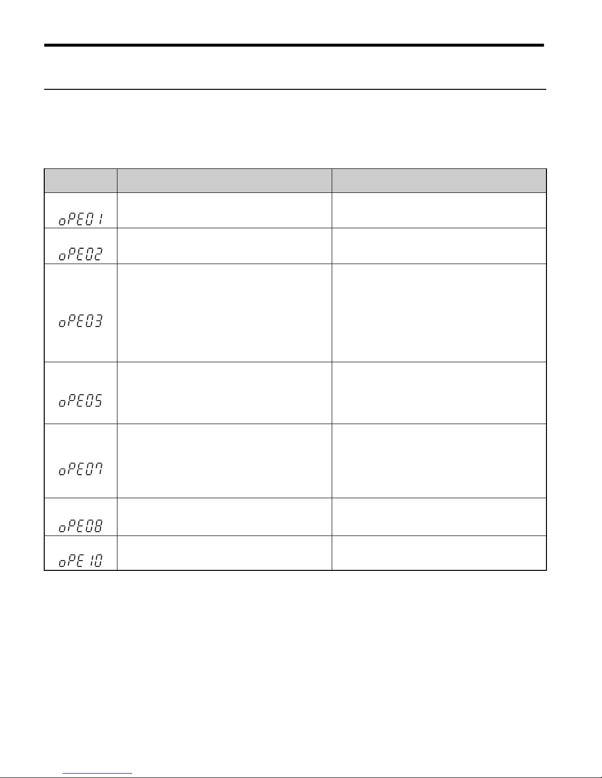
Operator Programing Errors
An Operator Programming Error (OPE) occurs when an inapplicable parameter is set or an
individual parameter setting is inappropriate. When an OPE error is displayed, press the
ENTER button to display U1-18 (OPE fault constant). This monitor will display the parameter that is causing the OPE error.
LED Operator
Display
Cause Corrective Action
oPE01
Drive capacity and value set to o2-04 do not
match.
Correct the value set to o2-04.
oPE02
Parameters were set outside the allowable setting
range.
Set parameters to the proper values.
oPE03
A contradictory setting is assigned to multi-function contact inputs H1-01 through to H1-06.
• The same function is assigned to two inputs.
(this excludes “External fault” and “Not used”)
• Input functions which require the setting of
other input functions were set alone.
• Input functions that are not allowed to be used
simultaneously have been set.
• Fix any incorrect settings.
• Refer to the Technical Manual for more details.
oPE05
• The run command source (b1-02) or frequency
reference source (b1-01) is set to 3 but no
option board is installed.
• The frequency reference source is set to pulse
input but H6-01 is not 0.
• Install the required option board.
• Correct the values set to b1-01 and b1-02.
oPE07
Settings to multi-function analog inputs H3-02
and H3-10 and PID functions conflict.
• H3-02 and H3-10 are set to the same value.
(this excludes settings “0” and “F”)
• PID functions have been assigned to both analog inputs and the pulse input at the same time.
• Fix any incorrect setting.
• Refer to the Technical Manual for more details.
oPE08
A function has been set that cannot be used in the
control mode selected.(might appear after control
mode change)
• Fix any incorrect setting.
• Refer to the Technical Manual for more details.
oPE10
The V/f pattern setting is incorrect.
• Check the V/f pattern settings.
• Refer to the Technical Manual for more details.
Page 37

7 Troubleshooting
YASKAWA Europe TOEP C710606 15C YASKAWA AC Drive - V1000 Quick Start Guide EN 35
ENGLISH
Auto-Tuning Errors
LED Operator
Display
Cause Corrective Action
Er-01
Motor data fault
The input motor data are not valid. (e.g. the base
frequency and base speed do not fit).
Re-enter the data and repeat Auto-Tuning.
Er-02
Minor Fault
• The wiring is faulty.
• The load is too heavy.
• Check the wiring.
• Check the load. Always perform Auto-Tuning
with the load decoupled from the motor.
Er-03
The STOP button was pressed and Auto-Tuning
was canceled.
Repeat the Auto-Tuning.
Er-04
Resistance fault
• Wrong input data.
• Auto tuning exceeded the given time frame.
• Calculated values out of range.
• Check the input data.
• Check the wiring.
• Re-enter the data and repeat the Auto-Tuning.
Er-05
No-Load Current Error
• Incorrect data was entered.
• Auto tuning took too long.
• Calculated values out of range.
Er-08
Rated Slip Error
• Wrong data input.
• Auto tuning exceeded the given time frame.
• Calculated values out of range.
Er-09
Acceleration error
The motor did not accelerate for the specified
acceleration time.
• Increase the acceleration time C1-01.
• Check the torque limits L7-01 and L7-02.
Er-11
Motor speed fault.
The torque reference was too high.
• Increase the acceleration time (C1-01).
• If possible, disconnect the load.
Er-12
Current detection error
• One or all output phases are lost.
• Current is either too low or exceeds the drives
rating.
• The current sensors are faulty.
• Check the wiring.
• Make sure, that the drive rating fits to the motor.
• Check the load. (Auto-Tuning should have been
performed without the load connected.)
• Replace the drive.
End1
Rated current alarm
• The torque reference exceeded 20% during
Auto-Tuning.
• The calculated no-load current is above 80%
of the motor rated current.
• Check the V/f pattern setting.
• Perform Auto-Tuning without the load connected.
• Check the input data and repeat Auto-Tuning.
End2
Motor iron-core saturation alarm
• Calculated core saturation values out of range.
• Incorrect data was entered.
• Check the input data.
• Check the motor wiring.
• Perform Auto-Tuning without load connected.
End3
Rated current alarm Check the input data and repeat tuning.
Page 38
EN 36 YASKAWA Europe TOEP C710606 15C YASKAWA AC Drive - V1000 Quick Start Guide
8 Instructions for UL and cUL
8 Instructions for UL and cUL
UL Standards Compliance
This drive is tested in accordance with UL standard UL508C, File No. E131457 and complies with UL requirements. To ensure continued compliance when using this drive in combination with other equipment, meet the following conditions:
Installation Area
Do not install the drive to an area greater than pollution severity 2 (UL standard).
Main Circuit Terminal Wiring
Yaskawa recommends using UL-listed copper wires (rated at 75°C) and closed-loop connectors or CSA-certified ring connectors sized for the selected wire gauge to maintain proper
clearances when wiring the drive. Use the correct crimp tool to install connectors per manufacturer recommendation. The following table lists a suitable closed-loop connector manufactured by JST Corporation.
Closed-Loop Crimp Terminal Size (JIS C 2805) (same for 200 V and 400 V)
Wire Gauge
mm
2
(AWG)
Terminal Screws
Crimp Terminal
Model Number
Tightening Torque
Nm
(lbin.)
0.75
(18)
M3.5 R1.25-3.5
0.8 to 1.0
(7.1 to 8.9)
M4 R1.25-4
1.2 to 1.5
(10.6 to 13.3)
1.25
(16)
M3.5 R1.25-3.5
0.8 to 1.0
(7.1 to 8.9)
M4 R1.25-4
1.2 to 1.5
(10.6 to 13.3)
2
(14)
M3.5 R2-3.5
0.8 to 1.0
(7.1 to 8.9)
M4 R2-4
1.2 to 1.5
(10.6 to 13.3)
M5 R2-5
2.0 to 2.5
(17.7 to 22.1)
M6 R2-6
4.0 to 5.0
(35.4 to 44.3)
Page 39

8 Instructions for UL and cUL
YASKAWA Europe TOEP C710606 15C YASKAWA AC Drive - V1000 Quick Start Guide EN 37
ENGLISH
Note: Use crimp insulated terminals or insulated tubing for wiring these connections.
Wires should have a continuous maximum allowable temperature of 75°C 600 V
UL approved vinyl sheathed insulation. Ambient temperature should not exceed
30°C.
Input Fuse Selection
Use the fuses listed up in the table on page 12 when wiring the main circuit.
3.5/5.5
(12/10)
M4 R5.5-4
1.2 to 1.5
(10.6 to 13.3)
M5 R5.5-5
2.0 to 2.5
(17.7 to 22.1)
M6 R5.5-6
4.0 to 5.0
(35.4 to 44.3)
M8 R5.5-8
9.0 to 11.0
(79.7 to 97.4)
8
(8)
M4 8-4
1.2 to 1.5
(10.6 to 13.3)
M5 R8-5
2.0 to 2.5
(17.7 to 22.1)
M6 R8-6
4.0 to 5.0
(35.4 to 44.3)
M8 R8-8
9.0 to 11.0
(79.7 to 97.4)
14
(6)
M4 14-4
1.2 to 1.5
(10.6 to 13.3)
M5 R14-5
2.0 to 2.5
(17.7 to 22.1)
M6 R14-6
4.0 to 5.0
(35.4 to 44.3)
M8 R14-8
9.0 to 11.0
(79.7 to 97.4)
22
(4)
M6 R22-6
4.0 to 5.0
(35.4 to 44.3)
M8 R22-8
9.0 to 11.0
(79.7 to 97.4)
30/38
(3/2)
M8 R38-8
9.0 to 11.0
(79.7 to 97.4)
<1> Use the specified crimp terminals(Model No.:14-NK4) when using CIMR-VC2A0030,
VC2A0040, VC4A0023 with the wire 14mm
2
(AWG:6).
Wire Gauge
mm
2
(AWG)
Terminal Screws
Crimp Terminal
Model Number
Tightening Torque
Nm
(lbin.)
Page 40

8 Instructions for UL and cUL
EN 38 YASKAWA Europe TOEP C710606 15C YASKAWA AC Drive - V1000 Quick Start Guide
Low Voltage Wiring for Control Circuit Terminals
Wire low voltage wires with NEC Class 1 circuit conductors; refer to national state or local
codes for wiring. Use a class 2 (UL regulations) power supply for the control circuit terminal.
Control Circuit Terminal Power Supply
Drive Short-Circuit Rating
This drive has undergone the UL short-circuit test, which certifies that during a short circuit
in the power supply the current flow will not rise above 30,000 Amps maximum at 240 V for
200 V class drives and 440 V for 400 V class drives.
• The MCCB and breaker protection and fuse ratings (refer to the preceding table) shall be
equal to or greater than the short-circuit tolerance of the power supply being used.
• Suitable for use on a circuit capable of delivering not more than 30,000 RMS symmetrical
amperes for 240 V in 200 V class drives (up to 440 V for 400 V class drives) motor overload protection
Drive Motor Overload Protection
Set parameter E2-01 (motor rated current) to the appropriate value to enable motor overload
protection. The internal motor overload protection is UL listed and in accordance with the
NEC and CEC.
E2-01 Motor Rated Current
Setting Range: Model Dependent
Factory Default: Model Dependent
The motor rated current parameter (E2-01) protects the motor and allows for proper vector
control when using open loop vector or flux vector control methods (A1-02 = 2 or 3). The
motor protection parameter L1-01 is set as factory default. Set E2-01 to the full load amps
(FLA) stamped on the nameplate of the motor.
Input / Output Terminal Signal Power Supply Specifications
Multi-function photocoupler outputs P1, P2, PC Requires class 2 power supply.
Multi-function digital inputs
S1, S2, S3, S4,
S5, S6, SC
Use the internal LVLC power supply of the drive.
Use class 2 for external power supply.
Multi function analog inputs +V, A1, A2, AC
Use the internal LVLC power supply of the drive.
Use class 2 for external power supply.
Pulse train input RP
Use the internal LVLC power supply of the drive.
Use class 2 for external power supply.
Pulse train output MP
Use the internal LVLC power supply of the drive.
Use class 2 for external power supply.
Page 41

8 Instructions for UL and cUL
YASKAWA Europe TOEP C710606 15C YASKAWA AC Drive - V1000 Quick Start Guide EN 39
ENGLISH
The operator must enter the rated current of the motor (T1-04) in the menu during auto-tuning. If the auto-tuning operation completes successfully (T1-02 = 0), the value entered into
T1-04 will automatically write into E2-01.
L1-01 Motor Overload Protection Selection
The drive has an electronic overload protection function (OL1) based on time, output current, and output frequency, which protects the motor from overheating. The electronic thermal overload function is UL-recognized, so it does not require an external thermal overload
relay for single motor operation.
This parameter selects the motor overload curve used according to the type of motor applied.
Overload Protection Settings
Disable the electronic overload protection (L1-01 = “0: Disabled”) and wire each motor with
its own motor thermal overload when connecting the drive to more than one motor for
simultaneous operation.
Enable the motor overload protection (L1-01 = 1, 2, or 3) when connecting the drive to a single motor unless there is another means of preventing motor thermal overload. The electronic thermal overload function causes an OL1 fault, which shuts off the output of the drive
and prevents additional overheating of the motor. The motor temperature is continually calculated as long as the drive is powered up.
Setting L1-01 = 1 selects a motor with limited cooling capability below rated (base) speed
when running at 100% load. The OL1 function derates the motor any time it is running
below base speed.
Setting L1-01 = 2 selects a motor capable of cooling itself over a 10:1 speed range when running at 100% load. The OL1 function derates the motor when it is running at 1/10 or less of
its rated speed.
Setting L1-01 = 3 selects a motor capable of cooling itself at any speed − including zero
speed − when running at 100% load. The OL1 function does not derate the motor at any
speed.
Setting L1-01 = 4 selects protection for a PM motor.
Setting Description
0 Disabled
1 Standard fan cooled motor (default)
2 Inverter duty motor with a speed range of 1:10
3 Vector motor with a speed range of 1:100
4 Permanent Magnet Motor
Page 42

8 Instructions for UL and cUL
EN 40 YASKAWA Europe TOEP C710606 15C YASKAWA AC Drive - V1000 Quick Start Guide
L1-02 Motor Overload Protection Time
Setting Range: 0.1 to 5.0 Minutes
Factory Default: 1.0 Minutes
The L1-02 parameter will set the allowed operation time before the OL1 fault will occur
when the drive is running at 60 Hz and 150% of the motor’s full load amp rating (E2-01).
Adjusting the value of L1-02 can shift the set of OL1 curves up the Y-axis of the diagram
below but will not change the shape of the curves.
L1-03 Motor Overload Alarm Operation Selection
L1-04 Motor Overload Fault Operation Selection
Motor Overload Protection Time
Setting Description
0 Ramp to Stop
1 Coast to Stop
2 Fast-Stop
3 Alarm Only (factory default)
Setting Description
0 Ramp to Stop
1 Coast to Stop (factory default)
2 Fast-Stop
Cold Start
Hot Start
Motor Current (%)
(E2-01=100 %)
10
7
3
1
0.4
0.1
0 100 200150
Time (minutes)
Page 43

Revision History
The revision dates and the numbers appear on the bottom of the back cover.
Date of Publication Rev. No. Section Revised Content
May 2007 −−First edition
April 2008 All
Addition: CIMR-VCBA0018
June 2008 Back cover
Revision: Address
September 2008 Chapter2
Addition: Dimensions
New models: CIMR-VC2A0030A to 2A0069A
CIMR-VC4A0018A to 4A0038A
December 2009
Revision
History
Revision: Example of the revision dates and the numbers
May 2010
Chapter 1
Chapter 3
Chapter 8
Revision of “Safety Instructions and General Warnings”
Revision of “Main and control circuit wiring”
Add new Chapter “Instructions for UL and cUL”
MANUAL NO.ޓTOEP C710606 15C
Published in GER May 2010 07-5
Date of publication
Place of publication
Date of original publication
1
Revision number
1
2
3
4
5
Page 44

1 YASKAWA ELECTRIC TOEP C710606 15C YASKAWA AC Drive - V1000 Quick Start Guide
08-5-1_YEU
Published in Germany May 2010 07-5
MANUAL NO. TOEP C710606 15C
5
YASKAWA Europe GmbH
In the event that the end user of this product is to be the military and said product is to be employed in any weapons systems or the manufacture
thereof, the export will fall under the relevant regulations as stipulated in the Foreign Exchange and Foreign Trade Regulations. Therefore, be sure
to follow all procedures and submit all relevant documentation according to any and all rules, regulations and laws that may apply.
Specifications are subject to change without notice for ongoing product modifications and improvements.
© 2010 YASKAWA Europe GmbH. All rights reserved.
Quick Start Guide
YASKAWA AC Drive V1000
Compact Vector Control Drive
EUROPEAN HEADQUARTERS
YASKAWA EUROPE GmbH
Hauptstraβe 185, 65760 Eschborn, Germany
Phone: +49 (0)6196 569 300
Fax: +49 (0)6196 569 398
E-mail: info@yaskawa.eu.com Internet: http://www.yaskawa.eu.com
YASKAWA ENGINEERING EUROPE GmbH
Hauptstraβe 185, 65760 Eschborn, Germany
Phone: +49 (0)6196 569 520 Fax: +49 (0)6196 569 598
E-mail: service@yaskawa.de Internet: http://www.yaskawa-eng.eu.com
U.S.A.
YASKAWA ELECTRIC AMERICA, INC.
2121 Norman Drive South, Waukegan, IL 60085, U.S.A.
Phone: +1 847 887 7000 Fax: +1 847 887 7370
Internet: http://www.yaskawa.com
JAPAN
YASKAWA ELECTRIC CORPORATION
New Pier Takeshiba South Tower, 1-16-1, Kaigan, Minatoku, Tokyo, 105-0022, Japan
Phone: +81 (0)3 5402 4511 Fax: +81 (0)3 5402 4580
Internet: http://www.yaskawa.co.jp
 Loading...