

Page 1
A
World of Automation Solutions
TM
CUSTOM SOFTWARE DESCRIPTION
DC INJECTION AND
TRIM CONTROL
Software Number: VSP018262 / VSP018252 Base Version: VSP010026 / VSP010105
Product: V7 Low & High HP Model Number: CIMR-V7AUXXXX1-052
Release Date: 5/14/03 Author: Ty Phillips Beta Version
Overview: Full range DC injection and DC injection via multi-function input functions are added.
Trim control increase/decrease by multi-function input is also included. This manual covers both the
low horsepower version VSP018262 and the high horsepower version VSP018252.
Revision History:
Date: 07/01/04, Rev: 04-07 Page 1 of 6 TM.V7SW.052
Page 2
1.0 Overview:
This software adds full range DC injection, as well as a DC injection command as a multi-function input
selection. DC injection causes DC current to flow in the motor windings, which aligns the motor poles and
provides deceleration and/or holding torque.
A trim control feature for the frequency reference (similar to the GPD515/G5 function) is also included.
This allows for increasing or decreasing (trimming) of the frequency reference by a programmed amount
through a multi-function input contact closure.
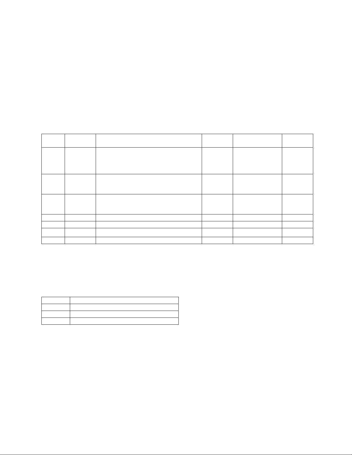
2.0 Related Parameters:
No.
Modbus
Address
Parameter Description Unit Setting Range Default
Stop Method:
n005 0105H
0: Ramp to stop
1: Coast to stop
- 0 ~ 2 0
2: Full range DC injection
Trim control level at maximum
n045 012DH
frequency (n011). 100% = n011
0.1% 0.0 ~ 100.0 *1 10.0
(maximum frequency).
Trim control level at minimum
n046 012EH
frequency (n016). 100% = n011
0.1% 0.0 ~ 100.0 *1 10.0
(maximum frequency).
n089 0159H DC Injection Current 1% 0 ~ 100 50
n090 0015A DC Injection Time at Stop 0.1 sec 0 ~ 25.5 0.0
n091 0015B DC Injection Time at Start 0.1 sec 0 ~ 25.5 0.0
n170 01AAH Minimum Baseblock Time 0.1 sec 0.1 ~ 1.0 0.5
*1: It is not possible to set n045 less than n046 or to set n046 greater than n045. . If n045 < n046 due to
setting by communication, an “oP9” alarm will be displayed.
3.0 Additional Multi-function Input Settings (n050 ~ n056):
Setting Description
28 DC Injection Command
29 Trim Control Increase
30 Trim Control Decrease
When n050 ~ n056 = 28, the corresponding input terminal (S1 ~ S7) is used for commanding DC
Injection.
When n050 ~ n056 = 29/30, the corresponding input terminals (S1 ~ S7) are used for the frequency
reference trim control increase/decrease function.
Date: 07/01/04, Rev: 04-07 Page 2 of 6 TM.V7SW.052
Page 3

4.0 Description of Functionality:
4.1 Full Range DC Injection
When n005 = 2 and the run command is removed, the drive will Baseblock for the time in parameter n170
(Minimum Baseblock Time) and then apply DC injection. The DC injection time is based on n090 (DC
Injection Time at Stop) and output frequency as shown below. Although the minimum Baseblock time
can be set as low as 0.1 Sec, caution should be observed when setting this parameter to avoid
Overvoltage or Overcurrent faults. The acceptable minimum setting will vary based on the motor and
application.
Output
Frequency
n170
Baseblock
Time
Command
Sec
n090 x 10
DC Injection Time = T
n090 (DC Injection
T
Run
Time at Stop)
n011 x 10%
(Max Frequency)
Output Frequency
(when run command
is removed)
Figure 1.0 Full Range DC Injection Timing Chart and Time Calculation Graph
n011
Hz
Date: 07/01/04, Rev: 04-07 Page 3 of 6 TM.V7SW.052
Page 4

4.2 DC Injection Multi-function Digital Input Command
• The DC Injection command will be active under the following conditions: the inverter is ready (i.e. not
in program mode or in a fault state), no run command is present, and the output frequency is less
than the Minimum Frequency (n016).
• The DC Injection Current Level is set by the standard parameter n089 (as a percentage of inverter
rated current).
• The DC Injection at Start and DC Injection at Stop parameters n090 and n091 have priority over the
external DC Injection command.
• Full range DC injection (n005 = 2) has priority over the external DC Injection command.
• The External Baseblock command has priority over the external DC Injection command.
• The RUN LED on the digital operator will be lit solid when the DC injection command is closed.
Run
Command
DC Injection
Command
10ms
Output
Frequency
Baseblock *
DC Injection DC Injection
* To prevent the 10ms Baseblock at the end of deceleration, set the DC Injection Time at Stop (n090) to 0.1 sec.
Figure 2.0 Multi-function Input DC Injection Command Timing Chart
Date: 07/01/04, Rev: 04-07 Page 4 of 6 TM.V7SW.052
Page 5

4.3 Frequency Reference Trim Control Function
When the trim control increase multi-function input is closed, the control trim level will be added to the
frequency reference. When the trim control decrease multi-function input is closed, the trim control level
will be subtracted from the frequency reference. The inverter must be in remote mode and the frequency
reference must be non-digital (n004 ≠ 1) for trim control to function. Also, trim control is disabled when
any of the multi-step speed reference inputs are closed. The trim control level is determined by the
frequency reference, n045 (Trim Control Level at Max Frequency), and n046 (Trim Control Level at Min
Frequency). See Figures 3.0 and 4.0 below.
%
n045 (Trim control level
at max frequency)
Trim Control Level
n046 (Trim control level
at min frequency)
n016
(Min Frequency)
Frequency Reference
(Before Trim Control)
n011
(Max Frequency)
Hz
Figure 3.0 Frequency Reference Trim Control Level Calculation Graph
Date: 07/01/04, Rev: 04-07 Page 5 of 6 TM.V7SW.052
Page 6

n045 (Trim Control Level
at Max Frequency)
n046 (Trim Control Level
at Min Frequency)
Frequency Reference
(Before Trim Control)
n033, n034
Frequency Reference
Upper / Lower limit
Figure 4.0 Frequency Reference Block Diagram Including Trim Control
Trim Control Increase
Multi-function Input
400 Hz
Trim Control Decrease
Multi-function Input
+
++
-
n033, n034
Frequency
Reference
Upper / Lower
Limit
n083 - n085
Jump
Frequencies
n016
Minimum
Frequency
400 Hz
Frequency
Reference
Date: 07/01/04, Rev: 04-07 Page 6 of 6 TM.V7SW.052
 Loading...