

Page 1

V
Software Numbers: VSP015166 (0.4 - 3.7kW)
VSP015292 (5.5 - 7.5kW)
Drive Part Number: CIMR-V7AM*-091
7 Custom Software
Kinetic Energy Back-up
(KEB)
Please note that the high horsepower version VSP015292
contains both the KEB function as well as the Traverse
function. The low horsepower traverse function is available
in software VSP018031 (CIMR-V7AM*-029). Refer to the
manual TM.V7SW.029 for Traverse function details.
Yaskawa Electric America, Inc.
Rev. <1>: July 19, 2001, VSP015164
Rev. <2>: January 8, 2002, VSP015166
Note: This manual is a YEA version of EZZ008774-2.
Date: 02/20/05, Rev: 05-02 Page 1 of 15 TM.V7SW.091
Page 2

1. Basic Specification
The basic specifications of KEB (Kinetic Energy Back-up) function are in conformance with the
description of the V7 Technical Manual (TM.V7.01). The following outlines the exclusive
specifications.
In order to prevent the drive from tripping at low voltage because of a momentary power loss or
power failure during operation or the motor from coasting for a long time period, the drive detects a
momentary power loss or power failure immediately when it occurs, and continues control using the
regenerative energy from the motor or decelerates to a stop. (The KEB function and the standard
software function momentary power loss ride through cannot be used simultaneously.)
The power supply is monitored according to the status of the multi-function digital input terminals;
the motor re-accelerates to the former speed at recovery from the power loss (Power loss
detecting relay must be mounted externally and the run command must be kept during momentary
power loss).
Automatic power loss detection function is available in order to make the motor switch to the
regenerated status promptly without tripping even at a momentary power loss or power failure
during high-load operation (However, perfect prevention from tripping depends on the load ratio,
load inertia, motor characteristics or capacitor size in the drive).
Note: This software does not support the energy-saving control.
Date: 02/20/05, Rev: 05-02 Page 2 of 15 TM.V7SW.091
Page 3
2. Details of KEB Specification
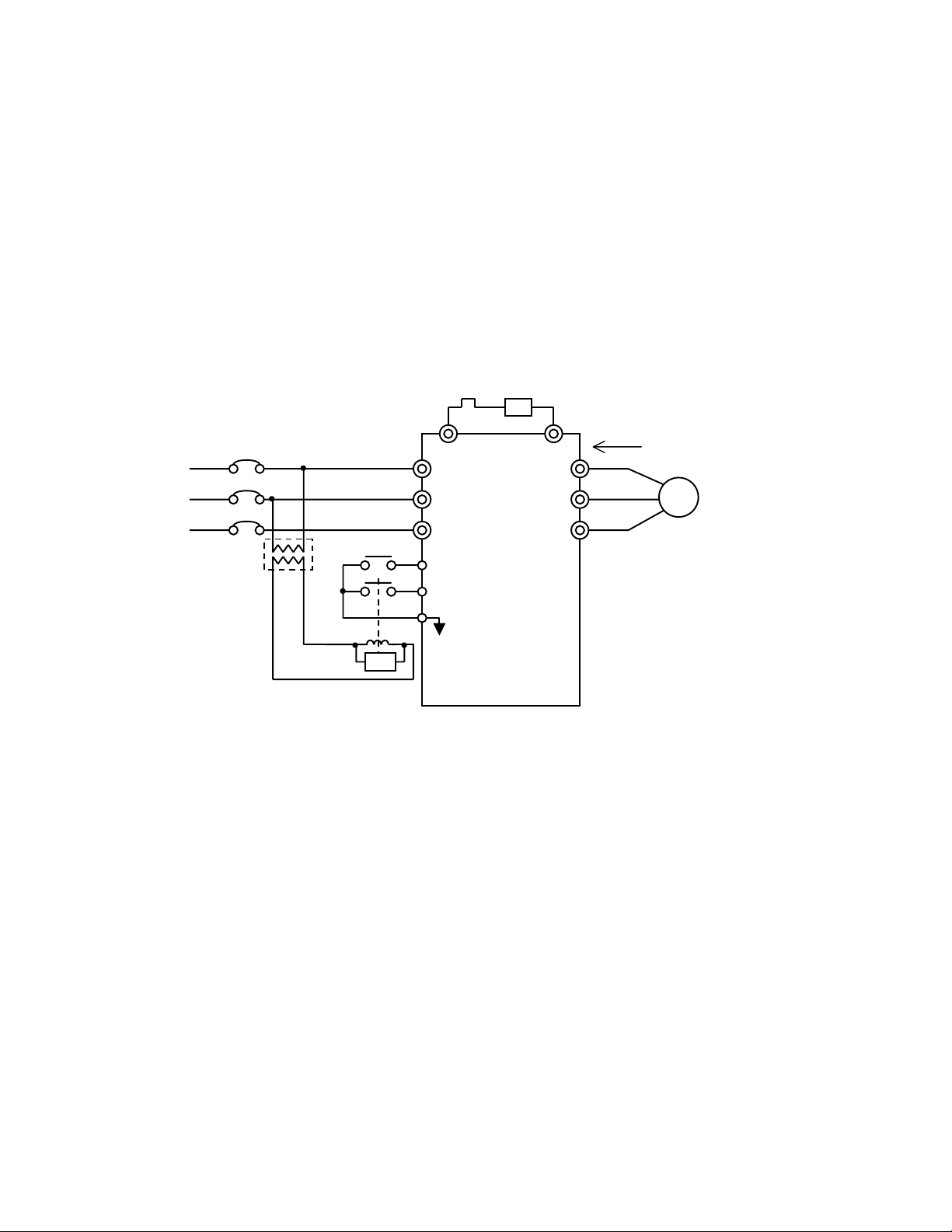
2.1 Basic Circuit
The KEB function becomes active when parameter n081 (Operation after Recovery from
Momentary Power Loss) is set to 3 (KEB Continuous Operation) or when a multi-function digital
input terminal is set to the KEB command. To restore the motor to the former operation status upon
recovery from a power loss, program one of the multi-function digital input terminals S1 to S7 (n050
to 056) to the KEB command (set values: 28 or 29) as shown in the following table. The run
command must also be maintained during the momentary power loss. When the run command is
removed during the momentary power loss, the drive continues decelerating to a stop even if power
returns.
Power Supply
Transformer
SA
B1 B2
R(L1)
S(L2)
T(L3)
S1 Forward Run
S7 KEB Command
n056=××
SC
R
U(T1)
V(T2)
W(T3)
Regenerative
Energy
IM
・ When regenerative energy is too
large and causes an overvoltage
(OV) trip, connect a braking
resistor.
Date: 02/20/05, Rev: 05-02 Page 3 of 15 TM.V7SW.091
Page 4

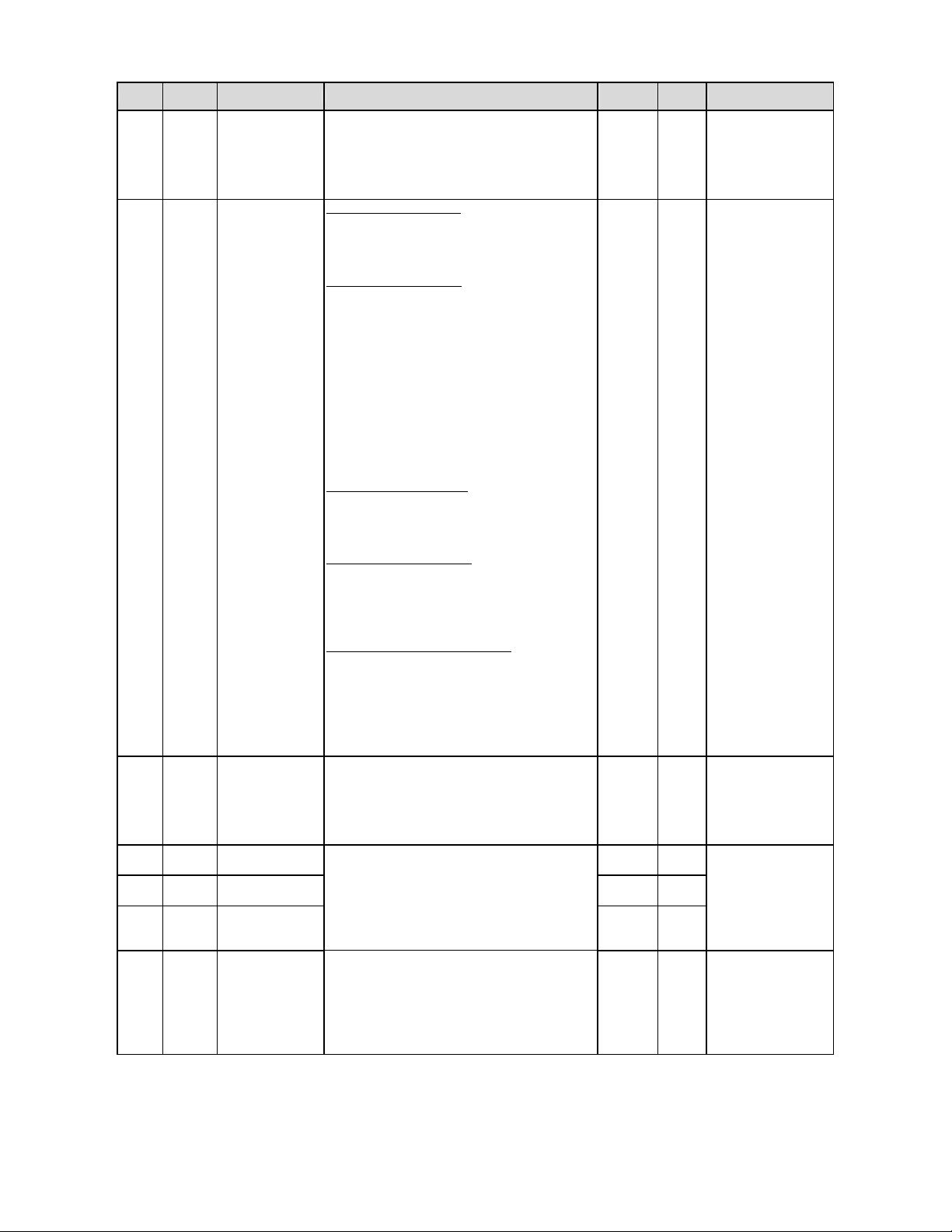
2.2 Added / Modified Parameters
No.
n045 Reserved KEB deceleration time 1
n046 Reserved KEB deceleration time 2
n047 Reserved KEB deceleration Ratio changeover time
n048 Reserved KEB starting voltage
n049 Reserved
n139 Energy saving control selection AVR time constant
n140 Energy saving coefficient K2 Undervoltage detection level
n141 Energy saving control voltage lower limit (@ 60Hz) Operation selection at power ON
n142 Energy saving control voltage lower limit (@ 6Hz)
n143 Power average time KEB compensation time
n144 Search operation voltage limit Power loss detection relay delay time
n145 Search operation voltage step (@100%) KEB re-acceptance prohibition time
n146 Search operation voltage step (@5%) Reserved
n159
n160
n161 Search operation power detection hold width Negative slope time
n162 Time constant of power detection filter Positiv e slope time
n170 Reserved Disturb waveform selection
n171 Reserved Stall prevention during acceleration selection
n172 Reserved Stall prevention voltage during acceleration
Upper voltage limit for energy saving control
Upper voltage limit for energy saving control
5.5/7.5kW standard
VSP010104
Stall prevention during deceleration (braking
Selection of br aking transistor ope ration
(@60Hz)
(@6Hz)
5.5/7.5kW KEB software
VSP01529x
transistor operational) voltage
during stop
Disturb waveform amplitude
Disturb waveform Jump
Note: Reference manual TM.V7SW.029 for details on the Traverse function.
2.3 Setting Range Changes
No. Parameter name Settings
Additional selections:
n050 -
n056
n057 -
n059
n081 Operation selection after momentary power loss
Multi-function input selection 1-7
Multi-function output selection 1-3
28: KEB command (NO)
29: KEB command (NC)
30: Disturb disable (opened = enabled)
31: Simple synchronized Accel/Decel
Additional selections:
22: During KEB operation
23: High-speed operation
24: During disturb up
25: During disturb
Additional selection:
3: KEB operation
Date: 02/20/05, Rev: 05-02 Page 4 of 15 TM.V7SW.091
Page 5
2.4 KEB Function Related Parameters
Modbus
No.
Register
n050 to
0132H to
n056
0138H
n057 to
0139H to
n059
013BH
n081 0151H
n045 012DH
n046 012EH
n047 012FH
n048 0130H
Name Description
Multi-function
Digital Input
Selection 1 - 7
Multi-function
Digital Output
Selection 1 - 3
Selection of
Operation after
Momentary Power
Loss
KEB Deceleration
Time 1
KEB Deceleration
Time 2
KEB Deceleration
Ratio Changeover
Time
KEB Starting
Voltage
Programming the KEB command (settings NO
contact: 28 or NC contact: 29) to a multi-function
digital input enables the KEB function, resulting in
re-acceleration at recovery from the power loss. If a
KEB command is not programmed, operation follows
the setting of parameter n081.
22: During KEB Operation
KEB signal is output dur ing KEB deceleration or
re-acceleration. This function is not active if the
KEB function is not programmed.
23: High-Speed Operation
<1>
This output closes during speed agree the
high-speed (main) frequency selection (when none
of the multi-function digital input functions Multi-step
Speed 1-4 or Jog are closed.).
The output cycles close/open every 0.5 seconds
during speed agree (except for the main speed
reference). The output cycles close/open every 1
second during acceleration or deceleration
regardless of the frequency reference. The output
opens while stopping. This function is active even if
the KEB function is not programmed.
15: Undervoltage Detection
In addition to the standard software conditions of
Undervoltage, the output will also close during
deceleration due to the KEB function.
30: Disturb waveform disable
Signal disables the disturb waveform.
Note: Function available in large HP version only
(VSP01529X).
31: Simple synchronized Accel/Decel
When the signal is input, the Accel/Decel times are
modified as follows:
Time = A ccel/D ecel time x (Fmax / Fref)
Note: Function available in large HP version only
(VSP01529X).
0: Operation not continued.
1: Ride Through. Operation continued at recovery
from power loss within 0.5 second
2: CPU Ride Through. Operation continued at
recovery from power loss (no fault output).
3: KEB Operation.
When KEB operation starts, the motor decelerate s
in KEB Deceleration Time 1. After KEB
Deceleration Ratio Changeover Time, the motor
decelerates in KEB Deceleration Time 2.
The setting unit of KEB Deceler ation Times 1 and 2
depends on the setting of parameter n018:
Accel/Decel Time Setting Unit.
The drive starts KEB operation when main circuit
DC bus voltage becomes less than the KEB
detection voltage value or when the multi-function
digital input function “KEB Command” is closed.
Note: Parameter n081: Momentary Powe r Loss
must be set to 3.
Setting
Range
0 to 3 3
0.00 to
6000 sec
0.00 to
6000sec
0.00 to
2.55sec
135 to
300Vdc
Initial
Value
KEB command cannot
- -
- -
10.0sec
10.0sec
0.10sec
225Vdc
be set to more than two
terminals and settings
28 and 29 cannot be
set at the same time.
All multi-function digital
100msec minimum
Parameters can be set
The setting range and
the initial value are
doubled for 460V units.
Remarks
outputs have a
state length.
during running.
Date: 02/20/05, Rev: 05-02 Page 5 of 15 TM.V7SW.091
Page 6

Modbus
No.
Register
n049 0131H
n139 018BH
n140 018CH
n141 018DH
n142 018EH
n143 018FH
n144 0190H
n145 0191
n146
0192H
<2>
n148
0194H
<2>
Name Description
Stall Prevention
during Deceleration
(and Braking
Transistor
Operational
Voltage)
AVR Time
Parameter
Undervoltage
Detection Level
Operation
Selection at Power
ON
Selection of
Transistor
Operation during
Stop
KEB Compensation
Time
Power Loss
Detection Relay
Delay Ti me
KEB
Re-acceptance
Prohibition Time
KEB
Re-acceleration
Time selection
KEB
Re-acceleration
Time
Sets the Stall Prevention during Decel operational
voltage and the braking transistor turn-on voltage
when a braking resi stor is provided.
Note: This function is active regardless of the KEB
function status or programming.
Sets the time constant of the output voltage AVR
(stabilization) function. AVR function is disabled
when the set value is 0.00sec.
Sets the Undervoltage (UV1) trip level of the DC bus.
Normally, this setting does not ha ve to be chang ed.
Note: This function is active regardless of the KEB
function status or programming.
Operation can be prohibited if the run command
(forward or reverse) is present when the power
supply is turned on. This can prevent accidental
machine operation.
0: Run Permitted
1: Run Prohibited
Note: This function is active regardless of the KEB
function status or programming.
Selects whether the braking transistor circuit is
active when the drive stops.
0: Disabled
1: Enabled
Note: This function is active regardless of the KEB
function status or programming.
An Undervoltage (UV1) trip will occur regardless of
the DC bus voltage when a momentary power loss
lasts more than the KEB Compens ation Time.
Note: This function is disabled when the set value is
0.00 seconds.
Prevents power loss recovery errors caused by a
delay in the opening of the power loss detection
relay by determining when the re-acceleration
sequence is needed. The drive monitors the status
of the KEB Command and the DC bus voltage.
Re-acceleration is made when the multi-function
input terminal and the main circuit DC bus bar
voltage are restored after the power loss detection
relay delay time elapses.
Note: A setting of 50msec will be used when the set
value is 0.0sec.
Re-acceptance of KEB operation can be prohibi ted
only for the specified time after re-acceleration
starts after a momentary power loss.
Note: This function is disabled when the set value is
0.00 seconds.
Selects the KEB re-acceleration time after the KEB
Command is removed.
0: Selected acceleration time (n019, n021, n041 or
n043)
1: KEB re-acceleration time (n148)
Sets the KEB re-accelerat ion time when KEB
re-accelerat i on time selection (n146) is 1.
Note: This parameter is not effective when n146 is
set to 0.
Setting
Range
300 to
400Vdc
0.00 to
2.55sec
135 to
210Vdc
0 to 1 0
0 to 1 0
0.0 to
25.5sec
0.0 to
25.5sec
0.0 to
25.5sec
0 to 1 0
0.00 to
6000sec
Initial
Value
400Vdc
1.00sec
150Vdc
0.0sec
0.1sec
0.0sec
10.0sec
The setting range and
the initial value are
doubled for 460V units.
Remarks
Date: 02/20/05, Rev: 05-02 Page 6 of 15 TM.V7SW.091
Page 7

2.5 Description of Operation
Basic Operation
Setting parameter n081 (Selection of Operation after Recovery from Momentary Power Loss) to 3
(KEB Operation Continued) or setting a multi-function digital input terminal to the KEB command
(NO contact: 28, NC contact: 29) enables the KEB function. The drive detects a power loss due to
the DC bus voltage or the multi-function digital input KEB command, decelerates immediately and
maintains its own DC bus voltage using the regenerative energy from the motor (load) to continue
control of the motor during deceleration.
If the KEB command is not programmed to a multi-function digital input and Selection of Operation
after Momentary Power Loss (parameter n081) is set to 3, KEB monitors the main circuit DC bus
voltage.
KEB Start Voltage: DC bus voltage ≦n048
・
KEB Release Voltage: DC bus voltage ≧n048+15VDC (30VDC for 460V units)
・
When the KEB command is set to the multi-function input and the run command is maintained
during the power loss, the drive monitors the status of the KEB command. After the Power Loss
Detection Relay Delay Time (n144) elapses, the drive will recovery from the power loss when the
KEB command turns OFF and DC bus voltage exceeds the KEB releasing voltage by
re-accelerating up to the speed obtained when KEB operation started. The motor decelerates to a
stop without re-acceleration if the run command turns OFF during a momentary power loss or a
long-term power loss occurs. (Unless the KEB command is set to the multi-function input, the drive
specifies the recovery from the power loss according to the status of DC bus bar voltage after the
Power Loss Detection Relay Delay Time (n144) elapses, and re-accelerates)
When the KEB operation starts, the motor decelerates in KEB Deceleration Time 1 (n045), and then
in KEB Deceleration Time 2 (n046) after KEB Deceleration Ratio Changeover Time (n047) elapses.
Therefore, set a fast deceleration ratio only when the KEB operation starts so that the drive DC bus
bar voltage can be maintained immediately.
Date: 02/20/05, Rev: 05-02 Page 7 of 15 TM.V7SW.091
Page 8

Multi-function Digital Outputs (Parameters n057 to n059)
When the KEB function is programmed, the Undervoltage detection signal (set value: 15) turns ON
with DC bus voltage less than the KEB Starting Voltage (n048) or during KEB deceleration while the
<1>
KEB running signal (set value: 22) turns ON during KEB deceleration or re-acceleration.
The high-speed running signal (set value: 23) is also available. This signal turns ON during speed
agreed of the high (main) speed reference. The high-speed frequency is defined as the reference
when digital input functions Multi-step Speeds 1-3 are OFF (open). The output turns ON/OFF in the
period of 1 second during acceleration or deceleration and in the period of 0.5 second during speed
agreed operation at any frequency reference other than high speed frequency reference, and OFF
during stop.
Mode
During Stop OFF OFF
During Acceleration or
Deceleration
During Speed Agreed ON ON/OFF in period of 0.5 second
High Speed (Main Speed
Frequency Reference Selected)
ON/OFF in period of 1 second ON/OFF in period of 1 second
Low Speed (Any Frequency Reference Other
than Main Speed Frequency Reference)
Stall Prevention Deceleration and Braking Transistor Operational Voltage (n049)
If an Overvoltage trip occurs when KEB starts (no braking resistor and stall prevention during
deceleration enabled: n092 = 0), the stall prevention deceleration operational voltage can be
reduced to avoid an OV trip. When several drives are connected on a common DC bus, connect a
braking resistor to the largest drive and refer to monitor display U-05 (DC bus voltage) to adjust this
parameter in order to avoid OV caused by uneven voltage detection.
Braking transistor operational voltage: DC bus voltage≧n049
・
Braking transistor releasing voltage: DC bus voltage≦n049 -10Vdc (20Vdc for 460V units)
・
AVR Time Constant (Parameter n139)
The time constant of the output voltage AVR (stabilization) function can be adjusted when the output
current or DC bus voltage oscillates during KEB operation. Adjust this parameter in small steps.
When the set value is 0.00sec, the AVR function is disabled.
Date: 02/20/05, Rev: 05-02 Page 8 of 15 TM.V7SW.091
Page 9

Undervoltage Detection Level (Parameter n140)
UV1 trip voltage is set when the KEB function is used. Even if KEB operation is active and the DC
bus voltage is reduced, when voltage becomes lower than this level, an Undervoltage (UV1) trip
occurs and the motor coasts.
・Undervoltage detection level: DC bus voltage≦n140
Undervoltage release level: DC bus voltage≧n140+15Vdc (30Vdc for 460V units)
・
Selection of Operation at Power ON (Parameter n141)
Setting parameter n141 to 1 can prohibit operation, at power up, when the run command from the
inputs terminals is already present. The digital operator displays EF blinking during prohibition of
operation. In this condition, cycle the run command to begin normal operation.
Selection of Transistor Operation during Stop (Parameter n142)
When Selection of Transistor Operation during Stop is set to a 1 (enabled), the braking transistor
turns ON when DC bus voltage exceeds the braking transistor operational voltage n049. In common
DC bus applications, set the main drive with the braking transistor to a 1 (enabled) and all others to
0 (disabled).
KEB Compensation Time (Parameter n143)
When the set value of KEB Compensation Time is other than 0.0sec, the drive measures the
duration of the KEB deceleration. If the time is greater than the KEB Compensation Time, an
Undervoltage (UV1) trip occurs and the motor coasts, regardless of the DC bus voltage.
Power Loss Relay Delay Time (Parameter n144)
Sets the time in order to avoid improper detection caused by delayed operation of the power loss
detection relay or frequent KEB operation when KEB operation is performed by DC bus voltage
detection. The drive will continue KEB deceleration after KEB start until the power loss detection
relay delay time elapses. Then it monitors the status of the multi-function digital input KEB
Command and the DC bus voltage and determines whether re-acceleration is required.
Date: 02/20/05, Rev: 05-02 Page 9 of 15 TM.V7SW.091
Page 10

KEB Re-acceptance Prohibition Time (Parameter n145)
Used when you do not want to repeat KEB operation when a long-term voltage reduction occu rs at
the level where the power loss detection relay does not operate or when a momentary power loss
occurs frequently. If the set value is other than 0.0sec, re-acceptance of the KEB Command is
prohibited from the time when re-acceleration starts at recovery from the power loss to when the set
time elapses. The drive will not perform KEB operation even if a momentary power loss occurs
during prohibition of re-acceptance. A DC bus voltage less than the Undervoltage Detection Level
(n140) result in an Undervoltage trip.
Precautions on Application
1.The multi-function digital input function Acceleration/deceleration Prohibition (set value: 16) is not
supported.
2. If the multi-function digital input function External Baseblock (set value: 12 or 13) is ON during
KEB or the run command is turned OFF when the stopping method is set to "coasting to a stop"
(n005 = 1), the drive enters the baseblock status, resulting in an Undervoltage (UV1) trip because
the drive cannot use regenerative energy from the motor (load). Consideration must be taken so
that the drive will not enter the baseblock status during KEB.
3. Increasing the S-curve time delays the start of KEB operation and can cause Undervoltage trips.
Do not change the initial value (No S-curve, n023 = 0).
Date: 02/20/05, Rev: 05-02 Page 10 of 15 TM.V7SW.091
Page 11

g
O
ON
O
ON
OFFON
2.6 Timing Charts
KEB Using DC Bus Voltage Detection
When a KEB command is not set to the multi-function input, KEB starts according to the drive’s DC
bus voltage. The drive specifies the recovery from power loss when this voltage is restored after
the Power Loss Detection Relay Delay Time elapses, and re-accelerates up to the former speed.
Turn OFF the run command at a momentary power loss or when a power failure occurs if
re-acceleration is not to be made at recovery from the power loss. The following shows the chart
diagram when the run command is turned OFF.
Drive main circuit
DC bus bar voltage
KEB Starting Voltage→
(n048)
Power loss
↓
←Braking Transistor Operational Voltage or Deceleration
Stall Prevention Operational Voltage.(n049)
Power Loss Detection Relay Delay Time (n144)
0
Drive Output Frequency
KEB Deceleration Time 1
(n045)
During under
e Detection
Vol t a
During KEB
Operation
RUN(FWD)
Command
KEB Deceleration Ratio Changeover Time (n047)
FF
FF
KEB Deceleration T im e 2 (n046)
0
After the under voltage detection, according to the
←
status of DC bus bar voltage
Note: To execute re-acceleration at recovery from the power loss, maintain the run command ON
during power loss. If recovery is sometimes detected improperly, set the Power Loss Detection
Relay Delay Time (n144) to a greater value than the possible maximum momentary power loss time.
Date: 02/20/05, Rev: 05-02 Page 11 of 15 TM.V7SW.091
Page 12

g
O
OFFON
O
O
ONONO
p
O
(
)
ON
t
r
p
p
(
)
KEB Command Using Multi-function Digital Input
Programming the KEB command to a multi-function digital input, KEB starts with the KEB Command
OR the drive’s DC bus voltage. The drive specifies the recovery from the power loss when these
signals are restored after the Power Loss Detection Relay Delay Time elapses, and re-accelerates
up to the former speed.
Drive main circuit
DC bus bar voltage
KEB Starting Voltage→
(n048)
Drive output frequency
KEB Deceleration Time 1
Multifunction
Multifunction
n045
ut
KEB Command
In
During under
ut
volta
Out
During KEB
o
RUN(FWD) command
KEB deceleration time 2 (n046)
e detection
eration
FF
FF
FF
Power
loss
↓
Power
Recovery
KEB Deceleration ratio changeover time (n047)
Power Loss Detection Relay Delay Time (n144)
Braking Transistor Operational Voltage or Deceleration
←Stall Prevention Operational Voltage (n049)
0
KEB Re-acceptance prohibition time (n145)
019or n021acceleration ratio
<2>Depending on set value of KEB
FF
n
re-acceleration time selection
0
FF
n146
Note: Set KEB Starting Voltage (n048) to a lower value when using the multi-function digital input
KEB command. This will prevent the DC bus voltage detection circuit from activating KEB.
KEB Without a Braking Resistor
Behavior when deceleration stall prevention operates at deceleration (Stall Prevention during
Deceleration Enabled: n092 = 0)
Drive main circui
DC bus bar voltage
KEB starting voltage→
Drive output frequency
Deceleration ratio or deceleration time
without KEB function →
Power Loss
↓
←Braking transistor operation voltage o
deceleration stall prevention operational
voltage(n049)
When deceleration stall prevention
operates at deceleration
0
0
Date: 02/20/05, Rev: 05-02 Page 12 of 15 TM.V7SW.091
Page 13

O
O
O
O
ON
O
O
(
)
ON
N
d
f
r
(
)
In Case of Rapid Deceleration Only When KEB Starts
Drive main circuit
DC bus bar voltage
KEB Starting Voltage
(n048)
Power Loss
Drive output
frequency
KEB Deceleration
Time 1
KEB Deceleration
Time 2
OFF OFF
Power Recovery
0
KEB Deceleration ratio changeover time (n047)
019or n021acceleration ratio
n
<2>Depending on set value of KEB
re-acceleration time selection
0
ONKEB command
n146
In case of power loss exceeding KEB compensation time
Operation when the multi-function input KEB command is used and the KEB compensation time is
other than 0.0sec.
Drive main circuit
DC bus bar voltage
Power loss
↓
Multifunction
Multifunction
KEB Starting Voltage→
n048
Drive output frequency
KEB Command
Input
During under
During KEB
Output
detection
→
KEB Compensation time(n143)
FF
FF
FF
N
0
UV1 trip occurs and the
motor coasts to a stop.
ote: Without recovery from the power loss within
the KEB compensation time, UV1 trip occurs.
FF
FF
0
Operation is performe
according to the status o
main circuit DC bus ba
voltage after tripping.
Date: 02/20/05, Rev: 05-02 Page 13 of 15 TM.V7SW.091
Page 14

2.7 How to Adjust
Cycle the power supply during constant speed operation or acceleration/deceleration to verify that
the drive decelerates or re-accelerates without tripping. If the drive trips during KEB, adjust the
following points.
Undervoltage (UV1) trip occurs when KEB starts.
(1)
・ Increase the KEB Starting Voltage (n048). However, increasing it excessively makes the
KEB operation perform even if the power supply is normal. Do not set it higher than power
supply voltage value
Reduce the KEB Deceleration Time 1 (n045) and increase the KEB Deceleration Ratio
・
×√2×
0.9.
Changeover Time (n047). Excessively rapid deceleration may make the motor stall.
(2) Undervoltage UV1 trip occurs during KEB deceleration.
Reduce the KEB Deceleration Time 2 (n046).
・
Undervoltage UV1 trip occurs at power loss during acceleration.
(3)
・ Increase the acceleration time.
Overvoltage OV trip occurs when KEB starts or during deceleration.
(4)
Increase KEB Deceleration Time 1 or 2 (n045, n046).
・
When a braking resistor is not provided, reduce the Deceleration Stall Prevention Operational
・
Voltage (n049). Reducing it excessively disables the drive to decelerate at normal
deceleration. Do not make it lower than power supply voltage×
Add a braking resistor if the above does not help.
・
2 ×1.2.
Output current or DC bus bar voltage oscillates during KEB operation.
(5)
Adjust the AVR Time Parameter (n139). However, reducing it excessively may cause
oscillation during normal operation.
Date: 02/20/05, Rev: 05-02 Page 14 of 15 TM.V7SW.091
Page 15

2.6 Guidelines of Selection and Adjustment
Regenerative power required to continue operation.(Pm)
Pm (kW) ≧ Load Power (kW) / (Drive Efficiency×Motor Efficiency)
Required deceleration torque (Tm)
Tm (Nm)
≧(60×Pm)×
3
10
/[2π×
Motor RPM]
Note: Tm must be within the range of motor (drive) stalling torque and overload capacity
Deceleration time (td)
td (sec) ≦ [2πx (Reflected Load Inertia + Motor Inertia)×(Motor RPM)/(60×Tm) ]
Note: In the above equation, Inertia is expressed in kgm2
Undervoltage (UV1)Trip time at power loss with no KEB (tuv)
tuv (msec) = [Drive Capacity (kW)/Load Power (kW)]×15msec
Required backup capacitor capacity to be added for given backup time (Cb)
3
Cb (μF) ≧ [(2×P1×10
×tb) /(Vn2-Vf2)×0.9]×106
Note: In the above equation;
PI: Load power (kW)
tb: Backup time (sec)
Vn: Main circuit DC bus bar voltage (Vdc)
Vf: Undervoltage (UV1) trip voltage (Vdc)
Date: 02/20/05, Rev: 05-02 Page 15 of 15 TM.V7SW.091
 Loading...