

Page 1
YASKAWA AC Drive P1000
Industrial Fan and Pump Drive
Quick Start Guide
Type: CIMR-PU
Models:
To properly use the product, read this manual thoroughly and retain
for easy reference, inspection, and maintenance. Ensure the end user
receives this manual.
200 V Class: 3/4 to 175 HP ND
400 V Class: 3/4 to 1000 HP ND
600 V Class: 2 to 250 HP ND
A
MANUAL NO. TOEP YAIP1U 01B
Page 2

Copyright © 2012 YASKAWA AMERICA, INC. All rights reserved.
No part of this publication may be reproduced, stored in a retrieval system, or transmitted, in any form or by any means,
mechanical, electronic, photocopying, recording, or otherwise, without the prior written permission of Yaskawa. No patent
liability is assumed with respect to the use of the information contained herein. Moreover, because Yaskawa is constantly
striving to improve its high-quality products, the information contained in this manual is subject to change without notice.
Every precaution has been taken in the preparation of this manual. Yaskawa assumes no responsibility for errors or omissions.
Neither is any liability assumed for damages resulting from the use of the information contained in this publication.
Page 3
Quick Reference
u
Easily Set Parameters for Specific Applications
Preset parameter defaults are available for setting up applications. Refer to Application Selection on
page 90.
Perform Auto-Tuning
Automatic tuning sets motor parameters. Refer to Auto-Tuning on page 118.
Maintenance Check Using Drive Monitors
Use drive monitors to check if fans, capacitors, or other components require maintenance. Refer to Performance Life Monitors Maintenance
Monitors on page 159.
Fault Display and Troubleshooting
Refer to Drive Alarms, Faults, and Errors on page 134.
Standards Compliance
Refer to European Standards on page 236 and Refer to UL and CSA Standards on page 244
<1> CE marking applies to 200 V class and 400 V class models only.
<1>
.
YASKAWA ELECTRIC TOEP YAIP1U 01B YASKAWA AC Drive - P1000 Quick Start Guide
3
Page 4

This Page Intentionally Blank
4
YASKAWA ELECTRIC TOEP YAIP1U 01B YASKAWA AC Drive - P1000 Quick Start Guide
Page 5

Table of Contents
QUICK REFERENCE........................................................................................ 3
i. PREFACE & GENERAL SAFETY................................................................... 11
i.1 Preface ........................................................................................................................ 12
Applicable Documentation....................................................................................................... 12
i.2 General Safety ............................................................................................................ 13
Supplemental Safety Information ............................................................................................ 13
Safety Messages..................................................................................................................... 14
General Application Precautions ............................................................................................. 15
Motor Application Precautions................................................................................................. 17
Drive Label Warning Example................................................................................................. 20
Warranty Information............................................................................................................... 20
1. RECEIVING .................................................................................................... 21
1.1 Model Number and Nameplate Check ........................................................................ 22
Nameplate ............................................................................................................................... 22
2. MECHANICAL INSTALLATION ...................................................................... 25
2.1 Mechanical Installation ................................................................................................ 26
Installation Environment .......................................................................................................... 26
Installation Orientation and Spacing........................................................................................ 26
Instructions on Installation Using the Eye Bolts ...................................................................... 28
3. ELECTRICAL INSTALLATION ....................................................................... 41
3.1 Standard Connection Diagram .................................................................................... 42
3.2 Main Circuit Connection Diagram................................................................................ 45
Three-Phase 200 V Class Models 2A0004 to 2A0081
Three-Phase 400 V Class Models 4A0002 to 4A0044
Three-Phase 600 V Class Models 5A0003 to 5A0032 .......................................................... 45
Three-Phase 200 V Class Models 2A0110, 2A0138
Three-Phase 400 V Class Models 4A0058, 4A0072
Three-Phase 600 V Class Models 5A0041, 5A0052 ............................................................. 45
Three-Phase 200 V Class Models 2A0169 to 2A0211
Three-Phase 400 V Class Models 4A0088 to 4A0139
Three-Phase 600 V Class Models 5A0062 to 5A0099 .......................................................... 46
Three-Phase 200 V Class Models 2A0250 to 2A0415
Three-Phase 400 V Class Models 4A0165 to 4A0675
Three-Phase 600 V Class Models 5A0125 to 5A0242 .......................................................... 46
YASKAWA ELECTRIC
TOEP YAIP1U 01B YASKAWA AC Drive - P1000 Quick Start Guide
5
Page 6

Table of Contents
Three-Phase 400 V Class Models 4A0930, 4A1200......................................................................... 47
12-Phase Rectification ...................................................................................................................... 47
3.3 Terminal Cover......................................................................................................................49
Models 2A0004 to 2A0081, 4A0002 to 4A0044, 5A0003 to 5A0032 (IP20/NEMA Type 1
Enclosure)........................................................................................................................................ 49
Models 2A0110 to 2A0250, 4A0208 to 4A0675, and 5A0125 to 5A0242 (IP00/Open Type
Enclosure)........................................................................................................................................ 50
3.4 Digital Operator and Front Cover ..........................................................................................51
Removing/Reattaching the Digital Operator...................................................................................... 51
Removing/Reattaching the Front Cover ............................................................................................ 51
3.5 Top Protective Cover.............................................................................................................54
Removing the Top Protective Cover ................................................................................................. 54
Reattaching the Top Protective Cover .............................................................................................. 54
3.6 Main Circuit Wiring ................................................................................................................55
Main Circuit Terminal Functions........................................................................................................ 55
Protecting Main Circuit Terminals ..................................................................................................... 56
Main Circuit Wire Gauges and Tightening Torque ............................................................................ 57
Main Circuit Terminal and Motor Wiring ............................................................................................ 64
3.7 Control Circuit Wiring ............................................................................................................66
Control Circuit Terminal Block Functions .......................................................................................... 66
Terminal Configuration ...................................................................................................................... 68
Wiring the Control Circuit Terminal ................................................................................................... 69
3.8 Control I/O Connections ........................................................................................................71
Sinking/Sourcing Mode for Digital Inputs .......................................................................................... 71
Using the Pulse Train Output ............................................................................................................ 72
Terminals A1, A2, and A3 Input Signal Selection.............................................................................. 72
Terminal AM/FM Signal Selection ..................................................................................................... 73
3.9 Connect to a PC ....................................................................................................................74
3.10 Wiring Checklist.....................................................................................................................75
4. START-UP PROGRAMMING & OPERATION........................................................ 77
4.1 Using the Digital Operator .....................................................................................................78
Keys and Displays............................................................................................................................. 78
LCD Display ...................................................................................................................................... 79
ALARM (ALM) LED Displays............................................................................................................. 80
LO/RE LED and RUN LED Indications.............................................................................................. 80
Menu Structure for Digital Operator .................................................................................................. 81
4.2 The Drive, Programming, and Clock Adjustment Modes ......................................................82
Real-Time Clock (RTC) ..................................................................................................................... 82
Clock Adjustment .............................................................................................................................. 82
Changing Parameter Settings or Values ........................................................................................... 85
Switching Between LOCAL and REMOTE........................................................................................ 86
4.3 Start-Up Flowchart ................................................................................................................88
4.4 Powering Up the Drive ..........................................................................................................89
Powering Up the Drive and Operation Status Display....................................................................... 89
4.5 Application Selection .............................................................................................................90
4.6 Basic Drive Setup Adjustments .............................................................................................91
EZ Sleep/Wake-up Function ............................................................................................................. 96
6
YASKAWA ELECTRIC TOEP YAIP1U 01B YASKAWA AC Drive - P1000 Quick Start Guide
Page 7

Table of Contents
4.7 Auto-Tuning.........................................................................................................................118
Types of Auto-Tuning ...................................................................................................................... 118
Auto-Tuning Interruption and Fault Codes ...................................................................................... 118
Auto-Tuning Operation Example ..................................................................................................... 119
4.8 No-Load Operation Test Run ..............................................................................................121
No-Load Operation Test Run .......................................................................................................... 121
4.9 Test Run with Load Connected ...........................................................................................123
Test Run with the Load Connected ................................................................................................. 123
4.10 Test Run Checklist ..............................................................................................................124
4.11 Fan and Pump Application Presets .....................................................................................125
A1-03 = 8008: Pump ....................................................................................................................... 125
A1-03 = 8009: Pump w/ PI .............................................................................................................. 125
A1-03 = 8010: Fan .......................................................................................................................... 126
A1-03 = 8011: Fan w/ PI ................................................................................................................. 126
Default Values for Fan and Pump Applications............................................................................... 127
4.12 Fan and Pump Application Preset Details...........................................................................128
5. TROUBLESHOOTING .......................................................................................... 133
5.1 Drive Alarms, Faults, and Errors .........................................................................................134
Types of Alarms, Faults, and Errors................................................................................................ 134
5.2 Fault Detection ....................................................................................................................135
Fault Displays, Causes, and Possible Solutions ............................................................................. 135
5.3 Alarm Detection...................................................................................................................146
Alarm Codes, Causes, and Possible Solutions ............................................................................... 146
5.4 Operator Programming Errors.............................................................................................149
Operator Programming Error Codes, Causes, and Possible Solutions........................................... 149
5.5 Auto-Tuning Fault Detection................................................................................................150
Auto-Tuning Codes, Causes, and Possible Solutions..................................................................... 150
5.6 Copy Function Related Displays .........................................................................................153
Tasks, Errors, and Troubleshooting ................................................................................................ 153
Fault Reset Methods ....................................................................................................................... 153
6. PERIODIC INSPECTION & MAINTENANCE ...................................................... 155
6.1 Inspection ............................................................................................................................156
Recommended Daily Inspection...................................................................................................... 156
Recommended Periodic Inspection................................................................................................. 157
6.2 Periodic Maintenance..........................................................................................................159
Replacement Parts.......................................................................................................................... 159
6.3 Drive Replacement..............................................................................................................161
Replacing the Drive ......................................................................................................................... 161
7. PERIPHERAL DEVICES & OPTIONS .................................................................. 163
7.1 Option Card Installation.......................................................................................................164
Prior to Installing the Option ............................................................................................................ 164
Communication Option Installation Example................................................................................... 165
A. SPECIFICATIONS ................................................................................................ 169
YASKAWA ELECTRIC TOEP YAIP1U 01B YASKAWA AC Drive - P1000 Quick Start Guide
7
Page 8

Table of Contents
A.1 Power Ratings .....................................................................................................................170
Three-Phase 200 V Class Drive Models 2A0004 to 2A0030 .......................................................... 170
Three-Phase 200 V Class Drive Models 2A0040 to 2A0211 .......................................................... 171
Three-Phase 200 V Class Drive Models 2A0250 to 2A0415 .......................................................... 172
Three-Phase 400 V Class Drive Models 4A0002 to 4A0031 .......................................................... 173
Three-Phase 400 V Class Drive Models 4A0038 to 4A0165 .......................................................... 174
Three-Phase 400 V Class Drive Models 4A0208 to 4A1200 .......................................................... 175
Three-Phase 600 V Class Drive Models 5A0003 to 5A0032 .......................................................... 176
Three-Phase 600 V Class Drive Models 5A0041 to 5A0099 .......................................................... 177
Three-Phase 600 V Class Drive Models 5A0125 to 5A0242 .......................................................... 178
A.2 Drive Specifications.............................................................................................................179
A.3 Drive Watt Loss Data ..........................................................................................................181
B. PARAMETER LIST ............................................................................................... 183
B.1 A: Initialization Parameters..................................................................................................184
A1: Initialization ............................................................................................................................... 184
A2: User Parameters....................................................................................................................... 184
B.2 b: Application.......................................................................................................................185
b1: Operation Mode Selection......................................................................................................... 185
b2: DC Injection Braking and Short Circuit Braking......................................................................... 185
b3: Speed Search............................................................................................................................ 186
b4: Timer Function .......................................................................................................................... 187
b5: PID Control................................................................................................................................ 187
b6: Dwell Function........................................................................................................................... 190
b8: Energy Saving ........................................................................................................................... 190
B.3 C: Tuning.............................................................................................................................191
C1: Acceleration and Deceleration Times ....................................................................................... 191
C2: S-Curve Characteristics............................................................................................................ 191
C3: Slip Compensation.................................................................................................................... 192
C4: Torque Compensation .............................................................................................................. 192
C6: Carrier Frequency..................................................................................................................... 192
B.4 d: References ......................................................................................................................193
d1: Frequency Reference................................................................................................................ 193
d2: Frequency Upper/Lower Limits ................................................................................................. 194
d3: Jump Frequency........................................................................................................................ 194
d4: Frequency Reference Hold and Up/Down 2 Function............................................................... 194
d6: Field Weakening and Field Forcing........................................................................................... 195
B.5 E: Motor Parameters ...........................................................................................................196
E1: V/f Pattern ................................................................................................................................. 196
E2: Motor 1 Parameters .................................................................................................................. 197
F4: Analog Monitor Card (AO-A3) ................................................................................................... 197
F6, F7: Communication Option Card............................................................................................... 198
B.6 H Parameters: Multi-Function Terminals.............................................................................202
H1: Multi-Function Digital Inputs ..................................................................................................... 202
H2: Multi-Function Digital Outputs................................................................................................... 205
H3: Multi-Function Analog Inputs .................................................................................................... 206
H4: Analog Outputs ......................................................................................................................... 208
H5: MEMOBUS/Modbus Serial Communication ............................................................................. 209
H6: Pulse Train Input....................................................................................................................... 209
B.7 L: Protection Function .........................................................................................................211
8
YASKAWA ELECTRIC TOEP YAIP1U 01B YASKAWA AC Drive - P1000 Quick Start Guide
Page 9

Table of Contents
L1: Motor Protection ........................................................................................................................ 211
L2: Momentary Power Loss Ride-Thru............................................................................................ 211
L3: Stall Prevention ......................................................................................................................... 212
L4: Speed Detection........................................................................................................................ 213
L5: Fault Restart.............................................................................................................................. 214
L6: Torque Detection....................................................................................................................... 214
L8: Drive Protection......................................................................................................................... 215
B.8 n: Special Adjustment..........................................................................................................217
n1: Hunting Prevention.................................................................................................................... 217
n3: High Slip Braking (HSB) and Overexcitation Braking................................................................ 217
B.9 o: Operator-Related Settings...............................................................................................218
o1: Digital Operator Display Selection............................................................................................. 218
o2: Digital Operator Keypad Functions ........................................................................................... 219
o3: Copy Function ........................................................................................................................... 219
o4: Maintenance Monitor Settings................................................................................................... 219
B.10 S: Special Application..........................................................................................................221
S1: Dynamic Noise Control Function .............................................................................................. 221
S2: Programmable Run Timers....................................................................................................... 221
S3: Secondary PI (PI2) Control ....................................................................................................... 223
S6: P1000 Protection ...................................................................................................................... 225
B.11 T: Motor Tuning ...................................................................................................................226
T1: Induction Motor Auto-Tuning..................................................................................................... 226
B.12 U: Monitors ..........................................................................................................................227
U1: Operation Status Monitors ........................................................................................................ 227
U2: Fault Trace................................................................................................................................ 229
U3: Fault History.............................................................................................................................. 230
U4: Maintenance Monitors .............................................................................................................. 231
U5: PID Monitors ............................................................................................................................. 233
U6: Operation Status Monitors ........................................................................................................ 233
C. STANDARDS COMPLIANCE ............................................................................... 235
C.1 European Standards ...........................................................................................................236
CE Low Voltage Directive Compliance............................................................................................ 236
EMC Guidelines Compliance .......................................................................................................... 238
C.2 UL and CSA Standards .......................................................................................................244
UL Standards Compliance .............................................................................................................. 244
CSA Standards Compliance............................................................................................................ 250
Drive Motor Overload Protection ..................................................................................................... 250
Precautionary Notes on External Heatsink (IP00/Open Type Enclosure) ....................................... 252
YASKAWA ELECTRIC TOEP YAIP1U 01B YASKAWA AC Drive - P1000 Quick Start Guide
9
Page 10

Table of Contents
This Page Intentionally Blank
10
YASKAWA ELECTRIC TOEP YAIP1U 01B YASKAWA AC Drive - P1000 Quick Start Guide
Page 11

i
Preface & General Safety
This section provides safety messages pertinent to this product that, if not heeded, may result in fatality,
personal injury, or equipment damage. Yaskawa is not responsible for the consequences of ignoring
these instructions.
i.1 PREFACE...............................................................................................................12
i.2 GENERAL SAFETY................................................................................................13
YASKAWA ELECTRIC TOEP YAIP1U 01B YASKAWA AC Drive - P1000 Quick Start Guide
11
Page 12
i.1 Preface
i.1 Preface
Yaskawa manufactures products used as components in a wide variety of industrial systems and equipment. The selection and
application of Yaskawa products remain the responsibility of the equipment manufacturer or end user. Yaskawa accepts no
responsibility for the way its products are incorporated into the final system design. Under no circumstances should any
Yaskawa product be incorporated into any product or design as the exclusive or sole safety control. Without exception, all
controls should be designed to detect faults dynamically and fail safely under all circumstances. All systems or equipment
designed to incorporate a product manufactured by Yaskawa must be supplied to the end user with appropriate warnings and
instructions as to the safe use and operation of that part. Any warnings provided by Yaskawa must be promptly provided to
the end user. Yaskawa offers an express warranty only as to the quality of its products in conforming to standards and
specifications published in the Yaskawa manual. NO OTHER WARRANTY, EXPRESS OR IMPLIED, IS OFFERED.
Yaskawa assumes no liability for any personal injury, property damage, losses, or claims arising from misapplication of its
products.
This manual is designed to ensure correct and suitable application of drives. Read this manual before attempting to install,
operate, maintain, or inspect a drive and keep it in a safe, convenient location for future reference. Be sure you understand all
precautions and safety information before attempting application.
u
Applicable Documentation
The following manuals are available for P1000 series drives:
P1000 Series AC Drive Quick Start Guide (TOEPYAIP1U01)
Read this guide first. This guide is packaged together with the product and contains basic information
required to install and wire the drive. It also gives an overview of fault diagnostics, maintenance, and
parameter settings. The purpose of this guide is to prepare the drive for a trial run with an application and
for basic operation. This manual is available for download on our documentation website,
www.yaskawa.com.
P1000 Series AC Drive Technical Manual (SIEPYAIP1U01)
This manual provides detailed information on parameter settings, drive functions, and MEMOBUS/
Modbus specifications. Use this manual to expand drive functionality and to take advantage of higher
performance features. This manual is available for download on our documentation website,
www.yaskawa.com.
12
YASKAWA ELECTRIC TOEP YAIP1U 01B YASKAWA AC Drive - P1000 Quick Start Guide
Page 13
i.2 General Safety
i.2 General Safety
u
Supplemental Safety Information
General Precautions
• The diagrams in this manual may be indicated without covers or safety shields to show details. Replace the covers or shields before
operating the drive and run the drive according to the instructions described in this manual.
• Any illustrations, photographs, or examples used in this manual are provided as examples only and may not apply to all products to
which this manual is applicable.
• The products and specifications described in this manual or the content and presentation of the manual may be changed without notice
to improve the product and/or the manual.
• When ordering a new copy of the manual due to damage or loss, contact your Yaskawa representative or the nearest Yaskawa sales
office and provide the manual number shown on the front cover.
• If nameplate becomes worn or damaged, order a replacement from your Yaskawa representative or the nearest Yaskawa sales office.
WARNING
Read and understand this manual before installing, operating or servicing this drive. The drive must be installed according
to this manual and local codes.
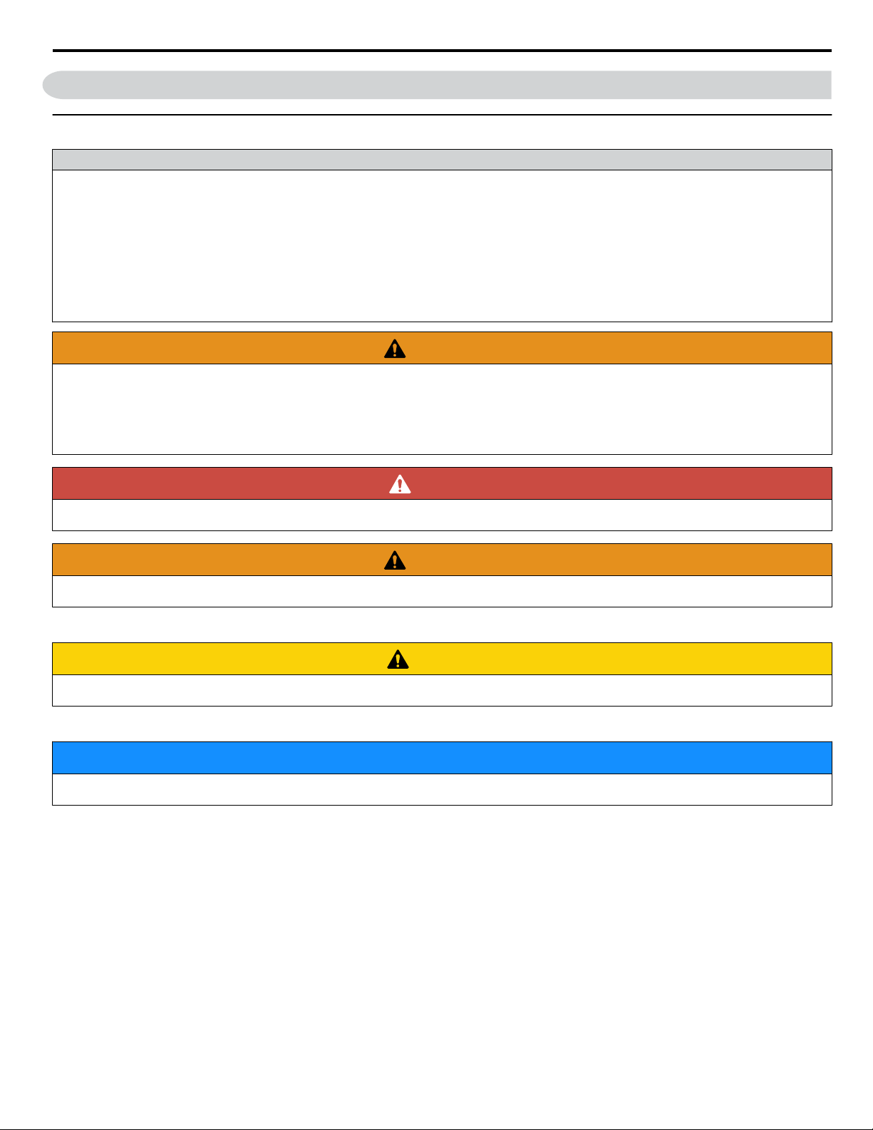
The following conventions are used to indicate safety messages in this manual. Failure to heed these messages could result
in serious or fatal injury or damage to the products or to related equipment and systems.
DANGER
Indicates a hazardous situation, which, if not avoided, will result in death or serious injury.
WARNING
Indicates a hazardous situation, which, if not avoided, could result in death or serious injury.
WARNING!
may also be indicated by a bold key word embedded in the text followed by an italicized safety message.
CAUTION
Indicates a hazardous situation, which, if not avoided, could result in minor or moderate injury.
CAUTION!
may also be indicated by a bold key word embedded in the text followed by an italicized safety message.
NOTICE
Indicates a property damage message.
NOTICE:
may also be indicated by a bold key word embedded in the text followed by an italicized safety message.
YASKAWA ELECTRIC TOEP YAIP1U 01B YASKAWA AC Drive - P1000 Quick Start Guide
13
Page 14

i.2 General Safety
u
Safety Messages
DANGER
Heed the safety messages in this manual.
Failure to comply will result in death or serious injury.
The operating company is responsible for any injuries or equipment damage resulting from failure to heed the warnings in
this manual.
Electrical Shock Hazard
Do not connect or disconnect wiring while the power is on.
Failure to comply will result in death or serious injury.
Before servicing, disconnect all power to the equipment. The internal capacitor remains charged even after the power supply
is turned off. After shutting off the power, wait for at least the amount of time specified on the drive before touching any
components.
WARNING
Sudden Movement Hazard
System may start unexpectedly upon application of power, resulting in death or serious injury.
Clear all personnel from the drive, motor and machine area before applying power. Secure covers, couplings, shaft keys and
machine loads before applying power to the drive.
Electrical Shock Hazard
Do not attempt to modify or alter the drive in any way not explained in this manual.
Failure to comply could result in death or serious injury.
Yaskawa is not responsible for any modification of the product made by the user. This product must not be modified.
Do not allow unqualified personnel to use equipment.
Failure to comply could result in death or serious injury.
Maintenance, inspection, and replacement of parts must be performed only by authorized personnel familiar with installation,
adjustment and maintenance of AC drives.
Do not remove covers or touch circuit boards while the power is on.
Failure to comply could result in death or serious injury.
Make sure the protective earthing conductor complies with technical standards and local safety regulations.
Because the leakage current exceeds 3.5 mA in models 4A0414 and larger, IEC/EN 61800-5-1 states that either the power
supply must be automatically disconnected in case of discontinuity of the protective earthing conductor or a protective
earthing conductor with a cross-section of at least 10 mm2 (Cu) or 16 mm2 (Al) must be used. Failure to comply may result
in death or serious injury.
Always use appropriate equipment for Ground Fault Circuit Interrupters (GFCIs).
The drive can cause a residual current with a DC component in the protective earthing conductor. Where a residual current
operated protective or monitoring device is used for protection in case of direct or indirect contact, always use a type B GFCI
according to IEC/EN 60755.
Fire Hazard
Do not use an improper voltage source.
Failure to comply could result in death or serious injury by fire.
Verify that the rated voltage of the drive matches the voltage of the incoming power supply before applying power.
14
YASKAWA ELECTRIC TOEP YAIP1U 01B YASKAWA AC Drive - P1000 Quick Start Guide
Page 15

i.2 General Safety
WARNING
Install adequate branch circuit protection according to applicable local codes and this Installation Manual. Failure
to comply could result in fire and damage to the drive or injury to personnel.
The device is suitable for use on a circuit capable of delivering not more than 100,000 RMS symmetrical amperes, 240 Vac
maximum (200 V class) and 480 Vac maximum (400 V class), and 600 Vac maximum (600 V class) when protected by
branch circuit protection devices specified in this document.
Crush Hazard
Do not use this drive in lifting applications without installing external safety circuitry to prevent accidental dropping
of the load.
The drive does not possess built-in load drop protection for lifting applications.
Failure to comply could result in death or serious injury from falling loads.
Install electrical and/or mechanical safety circuit mechanisms independent of drive circuitry.
CAUTION
Crush Hazard
Do not carry the drive by the front cover.
Failure to comply may result in minor or moderate injury from the main body of the drive falling.
NOTICE
Observe proper electrostatic discharge procedures (ESD) when handling the drive and circuit boards.
Failure to comply may result in ESD damage to the drive circuitry.
Do not perform a withstand voltage test on any part of the drive.
Failure to comply could result in damage to the sensitive devices within the drive.
Do not operate damaged equipment.
Failure to comply could result in further damage to the equipment.
Do not connect or operate any equipment with visible damage or missing parts.
If a fuse is blown or a Ground Fault Circuit Interrupter (GFCI) is tripped, check the wiring and the selection of the
peripheral devices.
Contact your supplier if the cause cannot be identified after checking the above.
Do not restart the drive immediately operate the peripheral devices if a fuse is blown or a GFCI is tripped.
Check the wiring and the selection of peripheral devices to identify the cause. Contact your supplier before restarting the
drive or the peripheral devices if the cause cannot be identified.
Do not expose the drive to halogen group disinfectants.
Failure to comply may cause damage to the electrical components in the drive.
Do not pack the drive in wooden materials that have been fumigated or sterilized.
Do not sterilize the entire package after the product is packed.
u
General Application Precautions
Selection
n
Installing a Reactor
Use an AC reactor or DC link choke in the following situations:
• to suppress harmonic current.
• to smooth peak current that results from capacitor switching.
• when the power supply is above 600 kVA.
YASKAWA ELECTRIC TOEP YAIP1U 01B YASKAWA AC Drive - P1000 Quick Start Guide
15
Page 16

i.2 General Safety
• when the drive is running from a power supply system with thyristor converters.
Note: A DC link choke is built in to drive models 2A0110 to 2A0415, 4A0058 to 4A1200, and 5A0041 to 5A0242.
4000
Power supply harmonics
reactor required
Power Supply
Capacity (kVA)
600
0
Drive Capacity (kVA)
Figure i.1 Installing a Reactor
Reactor
unnecessary
60 400
Drive Capacity
For specialized motors, make sure that the motor rated current is less than the rated output current for the drive.
When running more than one motor in parallel from a single drive, the capacity of the drive should be larger than [total motor
rated current × 1.1].
Starting Torque
The overload rating for the drive determines the starting and accelerating characteristics of the motor. Expect lower torque
than when running from line power. To get more starting torque, use a larger drive or increase both the motor and drive capacity.
Emergency Stop
During a drive fault condition, the output shuts off but the motor does not stop immediately. A mechanical brake may be
required when it is necessary to stop the motor faster than the ability of the Fast Stop function of the drive.
Options
NOTICE:
Yaskawa-approved devices to these terminals may damage the drive.
The B1, B2, ⊖, ⊕1, ⊕2, and ⊕3 terminals are used to connect optional drive-specific compatible devices only. Connecting non-
Repetitive Starting/Stopping
Laundry machines, punching presses, and other applications with frequent starts and stops often approach 150% of their rated
current values. Heat stress generated from repetitive high current will shorten the life span of the IGBTs.
Yaskawa recommends lowering the carrier frequency, particularly when audible noise is not a concern. It is beneficial to
reduce the load, increase the acceleration and deceleration times, or switch to a larger drive to help keep peak current levels
under 150%. Be sure to check the peak current levels when starting and stopping repeatedly during the initial test run, and
make adjustments accordingly.
Installation
n
Enclosure Panels
Keep the drive in a clean environment by installing the drive in an enclosure panel or selecting an installation area free of
airborne dust, lint, and oil mist. Be sure to leave the required space between drives to provide for cooling, and take proper
measures so the ambient temperature remains within allowable limits and keep flammable materials away from the drive.
Yaskawa offers protective designs for drives that must be used in areas subjected to oil mist and excessive vibration. Contact
Yaskawa or your Yaskawa agent for details.
Installation Direction
NOTICE:
Failure to comply may damage the drive due to improper cooling.
Install the drive upright as specified in the manual. Refer to Mechanical Installation on page 26 for more information on installation.
Settings
n
Upper Limits
NOTICE:
possible danger of accidentally operating equipment at higher than rated speed. The default setting for the maximum output frequency is
60 Hz.
The drive is capable of running the motor up to 400 Hz. Be sure to set the upper limit for the frequency of the drive to prevent the
DC Injection Braking
NOTICE:
16
Excessive current during DC Injection Braking and excessive duration of DC Injection Braking can cause motor overheat.
YASKAWA ELECTRIC TOEP YAIP1U 01B YASKAWA AC Drive - P1000 Quick Start Guide
Page 17

i.2 General Safety
Acceleration/Deceleration Times
Acceleration and deceleration times are affected by the amount of torque generated by the motor, the load torque, and the
inertia moment. Set a longer accel/decel time when Stall Prevention is enabled. The accel/decel times are lengthened for as
long as the Stall Prevention function is in operation. Install one of the available braking options or increase the capacity of the
drive for faster acceleration and deceleration.
General Handling
n
Wiring Check
NOTICE:
perform a final check of all sequence wiring and other connections before turning on the power and also check for short circuits on the
control terminals, which may damage the drive.
Selecting a Circuit Breaker or Circuit Interrupter
Do not connect power supply lines to output terminals U/T1, V/T2, or W/T3. Failure to comply will destroy the drive. Be sure to
Yaskawa recommends installing a Ground Fault Circuit Interrupter (GFCI) to the power supply side. The GFCI should be
designed for use with AC drives (e.g., Type B according to IEC 60755).
Select a Molded Case Circuit Breaker (MCCB) or GFCI with a rated current 1.5 to 2 times higher than the drive rated input
current to avoid nuisance trips caused by harmonics in the drive input current.
Magnetic Contactor Installation
WARNING!
resistors. Failure to comply may cause resistor overheating, fire, and injury to personnel.
NOTICE:
off and on more than once every 30 minutes. Frequent use can damage the drive. Use the drive to stop and start the motor.
Fire Hazard. Shut off the drive with a magnetic contactor (MC) when a fault occurs in any external equipment such as braking
To get the full performance life out of the electrolytic capacitors and circuit relays, refrain from switching the drive power supply
Inspection and Maintenance
WARNING!
amount of time specified on the drive before touching any components after shutting off the power. Failure to comply may cause injury to
personnel from electrical shock.
WARNING!
the cooling fan, shut off the power and wait at least 15 minutes to be sure that the heatsink has cooled down. Failure to comply may cause
burn injury to personnel.
Wiring
Electrical Shock Hazard. Capacitors in the drive do not immediately discharge after shutting off the power. Wait for at least the
Burn Hazard. Because the heatsink can get very hot during operation, take proper precautions to prevent burns. When replacing
Yaskawa recommends using ring terminals on all drive models. Drive models 2A0069 to 2A0415, 4A0058 to 4A1200, and
5A0041 to 5A0242 require the use of use ring terminals for UL/cUL compliance. Use only the tools recommended by the
terminal manufacturer for crimping.
Transporting the Drive
NOTICE:
ester, and other such harmful chemicals.
u
n
Low-Speed Range
Never steam clean the drive. During transport, keep the drive from coming into contact with salts, fluorine, bromine, phthalate
Motor Application Precautions
Standard Induction Motors
The cooling fan of a standard motor should sufficiently cool the motor at the rated speed. As the self-cooling capability of
such a motor reduces with the speed, applying full torque at low speed will possibly damage the motor. Reduce the load torque
as the motor slows to prevent motor damage from overheat. Figure i.2 shows the allowable load characteristics for a Yaskawa
standard motor. Use a motor designed specifically for operation with a drive when 100% continuous torque is needed at low
speeds.
YASKAWA ELECTRIC TOEP YAIP1U 01B YASKAWA AC Drive - P1000 Quick Start Guide
17
Page 18

50
3 6
60
60
70
80
90
100
25% ED (or 15 min)
40% ED (or 20 min)
60% ED (or 40 min)
Frequency (Hz)
Continuous operation
Torque
(%)
20
i.2 General Safety
Figure i.2 Allowable Load Characteristics for a Yaskawa Motor
Insulation Tolerance
NOTICE:
long wiring distances.
High-Speed Operation
NOTICE:
Contact the motor or machine manufacturer.
Consider motor voltage tolerance levels and motor insulation in applications with an input voltage of over 440 V or particularly
Problems may occur with the motor bearings and dynamic balance of the machine when operating a motor beyond its rated speed.
Torque Characteristics
Torque characteristics differ compared to operating the motor directly from line power. The user should have a full
understanding of the load torque characteristics for the application.
Vibration and Shock
The drive allows selection of high carrier PWM control and low carrier PWM. Selecting high carrier PWM can help reduce
motor oscillation.
Take particular caution when adding a variable speed drive to an application running a motor from line power at a constant
speed. If resonance occurs, install shock-absorbing rubber around the base of the motor and enable the Jump frequency selection
to prevent continuous operation in the resonant frequency range.
Audible Noise
The audible noise of the motor varies based on the carrier frequency setting. However, drive current derating may be required.
When using a high carrier frequency, audible noise from the motor is comparable to the motor noise generated when running
from line power.
Synchronous Motors
n
• Contact Yaskawa or a Yaskawa agent when planning to use a synchronous motor not endorsed by Yaskawa.
• Use a standard induction motor when running multiple synchronous motors simultaneously. A single drive does not have
this capability.
• A synchronous motor may rotate slightly in the opposite direction of the Run command at start depending on parameter
settings and rotor position.
• The amount of generated starting torque differs depending on the control mode and motor type. Set up the motor with the
drive after verifying the starting torque, allowable load characteristics, impact load tolerance, and speed control range.
Contact Yaskawa or a Yaskawa agent when planning to use a motor that does not fall within these specifications:
• To restart a coasting motor rotating over 200 Hz while in V/f Control, first use the Short Circuit Braking function to bring
the motor to a stop. Short Circuit Braking requires a special braking resistor. Contact Yaskawa or a Yaskawa agent for
details.
• To restart a coasting motor rotating below 200 Hz, use the Speed Search function if the motor cable is not too long. If the
motor cable is relatively long, stop the motor using Short Circuit Braking.
n
Multi-Pole Motor
The rated current of a multi-pole motor differs from that of a standard motor, so be sure to check the maximum current when
Specialized Motors
selecting a drive. Always stop the motor before switching between the number of motor poles. The motor will coast to stop if
a regen overvoltage (ov) fault occurs or if overcurrent (oC) protection is triggered.
18
YASKAWA ELECTRIC TOEP YAIP1U 01B YASKAWA AC Drive - P1000 Quick Start Guide
Page 19

i.2 General Safety
Submersible Motor
The rated current of a submersible motor is greater than that of a standard motor, so select the drive capacity accordingly. Use
a motor cable large enough to avoid decreasing the maximum torque level from voltage drop caused by a long motor cable.
Explosion-Proof Motor
The motor and the drive must be tested together to be certified as explosion-proof. The drive is not designed for explosionproof areas.
When attaching an encoder to an explosion-proof motor, make sure the encoder is also explosion-proof. Use an insulating
signal converter to connect the encoder signal lines to the speed feedback option card.
Geared Motor
Make sure that the gear and the lubricant are rated for the desired speed range to avoid gear damage when operating at low
speeds or very high speeds. Consult with the manufacturer for applications that require operation outside the rated speed range
of the motor or gear box.
Single-Phase Motor
Variable speed drives are not designed to operate with single phase motors. Using capacitors to start the motor causes excessive
current to flow and can damage drive components. A split-phase start or a repulsion start can burn out the starter coils because
the internal centrifugal switch is not activated. The drive is for use with three-phase motors only.
Motor with Brake
Take caution when using the drive to operate a motor with a built-in holding brake. If the brake is connected to the output side
of the drive, it may not release at start due to low voltage levels, so be sure to install a separate power supply for the motor
brake. Note that motors with built-in brakes tend to generate a fair amount of noise when running at low speeds.
Notes on Power Transmission Machinery
n
Installing an AC drive in machinery that was previously connected directly to the power supply will allow the machine to
operate at variable speeds. Continuous operation outside of the rated speeds can wear on lubrication material in gear boxes
and other power transmission parts. Make sure that lubrication is sufficient within the entire speed range to avoid machine
damage. Note that operation above the rated speed can increase the noise generated by the machine.
YASKAWA ELECTRIC TOEP YAIP1U 01B YASKAWA AC Drive - P1000 Quick Start Guide
19
Page 20
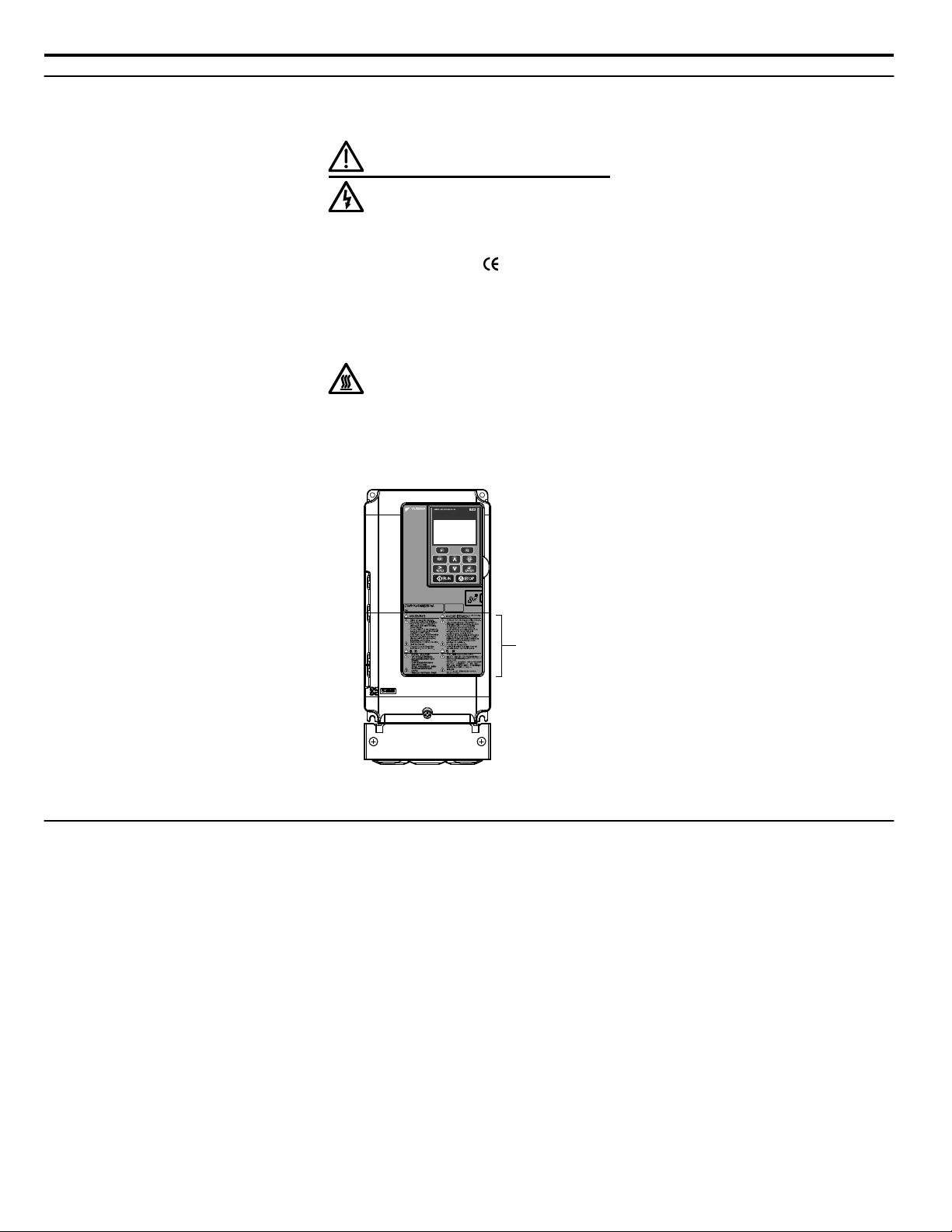
Warning Label
600V 3Phase 5.5kW/3.7kW
i.2 General Safety
u
Drive Label Warning Example
Always heed the warning information listed in Figure i.3 in the position shown in Figure i.4.
WARNING
Risk of electric shock.
●
Read manual before installing.
●
Wait 5 minutes for capacitor
discharge after disconnecting
power supply.
●
To conform to requirements,
make sure to ground the supply
neutral for 400V class.
●
After opening the manual switch
between the drive and motor,
please wait 5 minutes before
inspecting, performing
maintenance or wiring the drive.
Hot surfaces
●
Top and Side surfaces may
become hot. Do not touch.
Figure i.3 Warning Information Example
Figure i.4 Warning Information Position
u
Warranty Information
Restrictions
n
The drive is not designed or manufactured for use in devices or systems that may directly affect or threaten human lives or
health.
Customers who intend to use the product described in this manual for devices or systems relating to transportation, health
care, space aviation, atomic power, electric power, or in underwater applications must first contact their Yaskawa
representatives or the nearest Yaskawa sales office.
WARNING!
be installed in any location where failure of this product could involve or result in a life-and-death situation or loss of human life or in a facility
where failure may cause a serious accident or physical injury, safety devices must be installed to minimize the likelihood of any accident.
20
Injury to Personnel. This product has been manufactured under strict quality-control guidelines. However, if this product is to
YASKAWA ELECTRIC TOEP YAIP1U 01B YASKAWA AC Drive - P1000 Quick Start Guide
Page 21

1
Receiving
This chapter explains how to inspect the drive upon receipt, and gives an overview of the different
enclosure types and components.
1.1 MODEL NUMBER AND NAMEPLATE CHECK......................................................22
YASKAWA ELECTRIC TOEP YAIP1U 01B YASKAWA AC Drive - P1000 Quick Start Guide
21
Page 22
H
G
F
E
D
B
C
A
PRG : 8500
IND.CONT.EQ.
7J48 B
YASKAWA ELECTRIC CORPORATION
Assembled in USA
:
CIMR-PU2A0004FAA
PASS
MODEL
INPUT
OUTPUT
MASS
O / N
S / N
FILE NO
REV : A
: AC3PH 200-240V 50/60Hz 3. 9A
: AC3PH 0-240V 0-400Hz 3. 5A
: 3. 3 kg
:
:
: E131457 IP20
200/400 V Class
600 V Class
PRG : 8500
IND.CONT.EQ.
7J48 B
YASKAWA ELECTRIC CORPORATION
Assembled in USA
:
CIMR-PU5A0003FAA
: AC3PH 500-600V 50/60Hz 3. 6A
: AC3PH 0-600V 0-400Hz 2. 7A
: 3.4 kg
:
:
: E131457 IP20
PASS
MODEL
C/C
INPUT
OUTPUT
MASS
O / N
S / N
FILE NO
REV : A
H
G
F
E
D
A
B
C
: CIMR-PU5A0003FAA
6W3050-2-100 VAJ123456
J0073D207410100
C/C
CIMR-PU2A0004FAA:
6W3050-0-100 VAJ123456
J0073D207410100
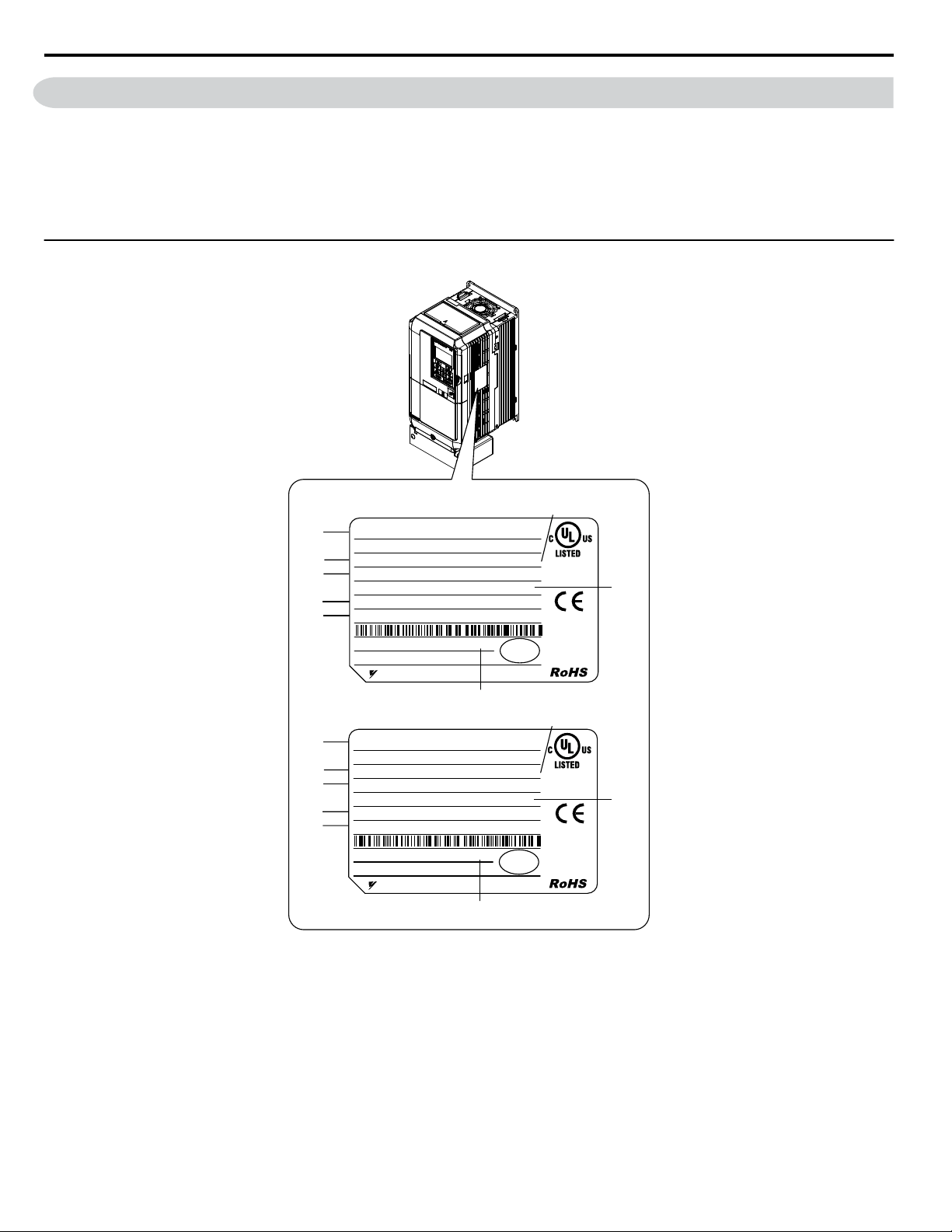
1.1 Model Number and Nameplate Check
1.1 Model Number and Nameplate Check
Please perform the following tasks after receiving the drive:
• Inspect the drive for damage.
If the drive appears damaged upon receipt, contact the shipper immediately.
• Verify receipt of the correct model by checking the information on the nameplate.
• If you have received the wrong model or the drive does not function properly, contact your supplier.
u
Nameplate
22
A – Normal Duty Amps
B – Software version
C – Enclosure type
D – Serial number
E – Lot number
F – Output specifications
G – Input specifications
H – AC drive model
Figure 1.1 Nameplate Information Example
YASKAWA ELECTRIC TOEP YAIP1U 01B YASKAWA AC Drive - P1000 Quick Start Guide
Page 23
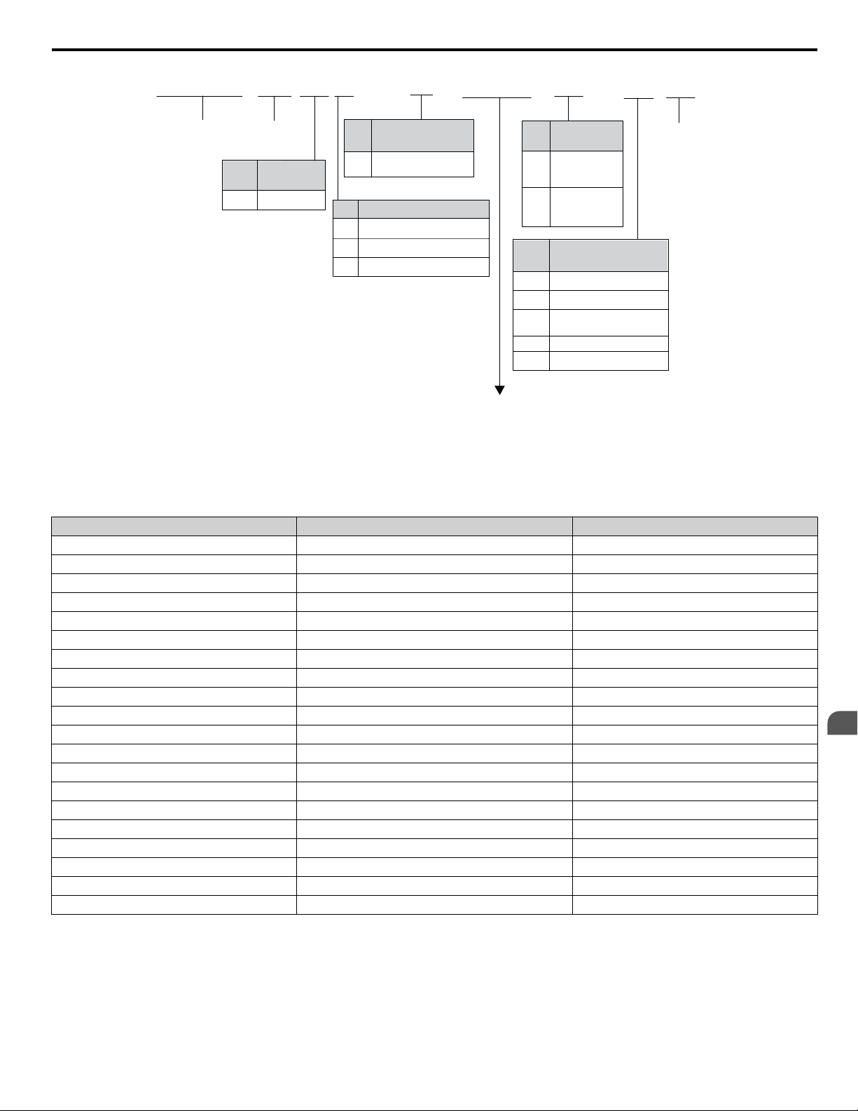
CIMR
-
P U 2 A
0021 F
A A
Drive
P1000
Series
No.
Enclosure
Type <1>
Design
Revision
Order
No.
Customized
Specifications
A Standard model
IP00/Open
Type
F
IP20/NEMA
Type 1
A
No.
Environmental
Specification <2>
K Gas-resistant
A
M
N
S
Standard
Humidity- and
dust-resistant
Oil-resistant
Vibration-resistant
Refer to the tables below
No.
Region
Code
USA
U
No. Voltage Class
3-phase, 380-480 Vac
3-phase, 200-240 Vac
2
4
3-phase, 500-600 Vac 5
1.1 Model Number and Nameplate Check
<1> Refer to Mechanical Installation on page 26 for differences regarding enclosure protection types and component
descriptions.
<2> Drives with these specifications do not guarantee complete protection for the environmental conditions indicated.
n
Three-Phase 200 V Class
Drive Model
2A0004 0.75 (0.75) 3.5
2A0006 1.1 (1) 6.0
2A0008 1.5 (2) 8.0
2A0010 2.2 (3) 9.6
2A0012 3.0 (3) 12
2A0018 3.7 (5) 17.5
2A0021 5.5 (7.5) 21
2A0030 7.5 (10) 30
2A0040 11 (15) 40
2A0056 15 (20) 56
2A0069 18.5 (25) 69
2A0081 22 (30) 81
2A0110 30 (40) 110
2A0138 37 (50) 138
2A0169 45 (60) 169
2A0211 55 (75) 211
2A0250 75 (100) 250
2A0312 90 (125) 312
2A0360 110 (150) 360
2A0415 110 (175) 415
Max. Motor Capacity kW (HP) Rated Output Current A
Receiving
1
YASKAWA ELECTRIC TOEP YAIP1U 01B YASKAWA AC Drive - P1000 Quick Start Guide
23
Page 24

1.1 Model Number and Nameplate Check
Three-Phase 400 V Class
n
Drive Model Max. Motor Capacity kW (HP) Rated Output Current A
4A0002 0.75 (0.75) 2.1
4A0004 1.5 (2) 4.1
4A0005 2.2 (3) 5.4
4A0007 3.0 (3) 6.9
4A0009 3.7 (5) 8.8
4A0011 5.5 (7.5) 11.1
4A0018 7.5 (10) 17.5
4A0023 11 (15) 23
4A0031 15 (20) 31
4A0038 18.5 (25) 38
4A0044 22 (30) 44
4A0058 30 (40) 58
4A0072 37 (50) 72
4A0088 45 (60) 88
4A0103 55 (75) 103
4A0139 75 (100) 139
4A0165 90 (125) 165
4A0208 110 (150) 208
4A0250 132 (200) 250
4A0296 160 (250) 296
4A0362 185 (300) 362
4A0414 220 (350) 414
4A0515 250 (400-450) 515
4A0675 355 (500-550) 675
4A0930 500 (750) 930
4A1200 630 (1000) 1200
Three-Phase 600 V Class
n
Drive Model
5A0003 1.5 (2) 2.7
5A0004 2.2 (3) 3.9
5A0006 3.7 (5) 6.1
5A0009 5.5 (7.5) 9
5A0011 7.5 (10) 11
5A0017 11 (15) 17
5A0022 15 (20) 22
5A0027 18.5 (25) 27
5A0032 22 (30) 32
5A0041 30 (40) 41
5A0052 37 (50) 52
5A0062 45 (60) 62
5A0077 55 (75) 77
5A0099 75 (100) 99
5A0125 90 (125) 125
5A0145 110 (150) 145
5A0192 160 (200) 192
5A0242 185 (250) 242
Max. Motor Capacity kW (HP) Rated Output Current A
24
YASKAWA ELECTRIC TOEP YAIP1U 01B YASKAWA AC Drive - P1000 Quick Start Guide
Page 25

2
Mechanical Installation
This chapter explains how to properly mount and install the drive.
2.1 MECHANICAL INSTALLATION..............................................................................26
YASKAWA ELECTRIC TOEP YAIP1U 01B YASKAWA AC Drive - P1000 Quick Start Guide
25
Page 26
2.1 Mechanical Installation
2.1 Mechanical Installation
This section outlines specifications, procedures, and the environment for proper mechanical installation of the drive.
u
Installation Environment
Install the drive in an environment matching the specifications in Table 2.1 to help prolong the optimum performance life of
the drive.
Table 2.1 Installation Environment
Environment Conditions
Installation Area Indoors
-10 °C to +40 °C (IP20/NEMA Type 1 enclosure)
-10 °C to +50 °C (IP00/Open Type enclosure)
Ambient Temperature
Humidity 95% RH or less and free of condensation
Storage Temperature -20 to +60 °C
Surrounding Area
Altitude 1000 m or lower, up to 3000 m with derating
Vibration
Orientation Install the drive vertically to maintain maximum cooling effects.
<1>
Models 4A0930 and 4A1200 are rated at 5.9 m/s2 (19.36 ft/s2)
NOTICE:
operation. If such devices must be used in close proximity to the drive, take proper steps to shield the drive from noise.
NOTICE:
could result in damage to the drive. Place a temporary cover over the top of the drive during installation. Remove the temporary cover before
drive start-up, as the cover will reduce ventilation and cause the drive to overheat.
Avoid placing drive peripheral devices, transformers, or other electronics near the drive as the noise created can lead to erroneous
Prevent foreign matter such as metal shavings and wire clippings from falling into the drive during installation. Failure to comply
Drive reliability improves in environments without wide temperature fluctuations.
When using the drive in an enclosure panel, install a cooling fan or air conditioner in the area to ensure that the air
temperature inside the enclosure does not exceed the specified levels.
Do not allow ice to develop on the drive.
Install the drive in an area free from:
• oil mist and dust
• metal shavings, oil, water, or other foreign materials
• radioactive materials
• combustible materials (e.g., wood)
• harmful gases and liquids
• excessive vibration
• chlorides
• direct sunlight.
10 to 20 Hz at 9.8 m/s2 (32.15 ft/s2)
20 to 55 Hz at 5.9 m/s2 (19.36 ft/s2) (Models 2A0004 to 2A0211, 4A0002 to 4A0165, and 5A0003 to 5A0099) or
2.0 m/s2 (6.56 ft/s2) (Models 2A0250 to 2A0415, 4A0208 to 4A1200, and 5A0125 to 5A0242)
<1>
u
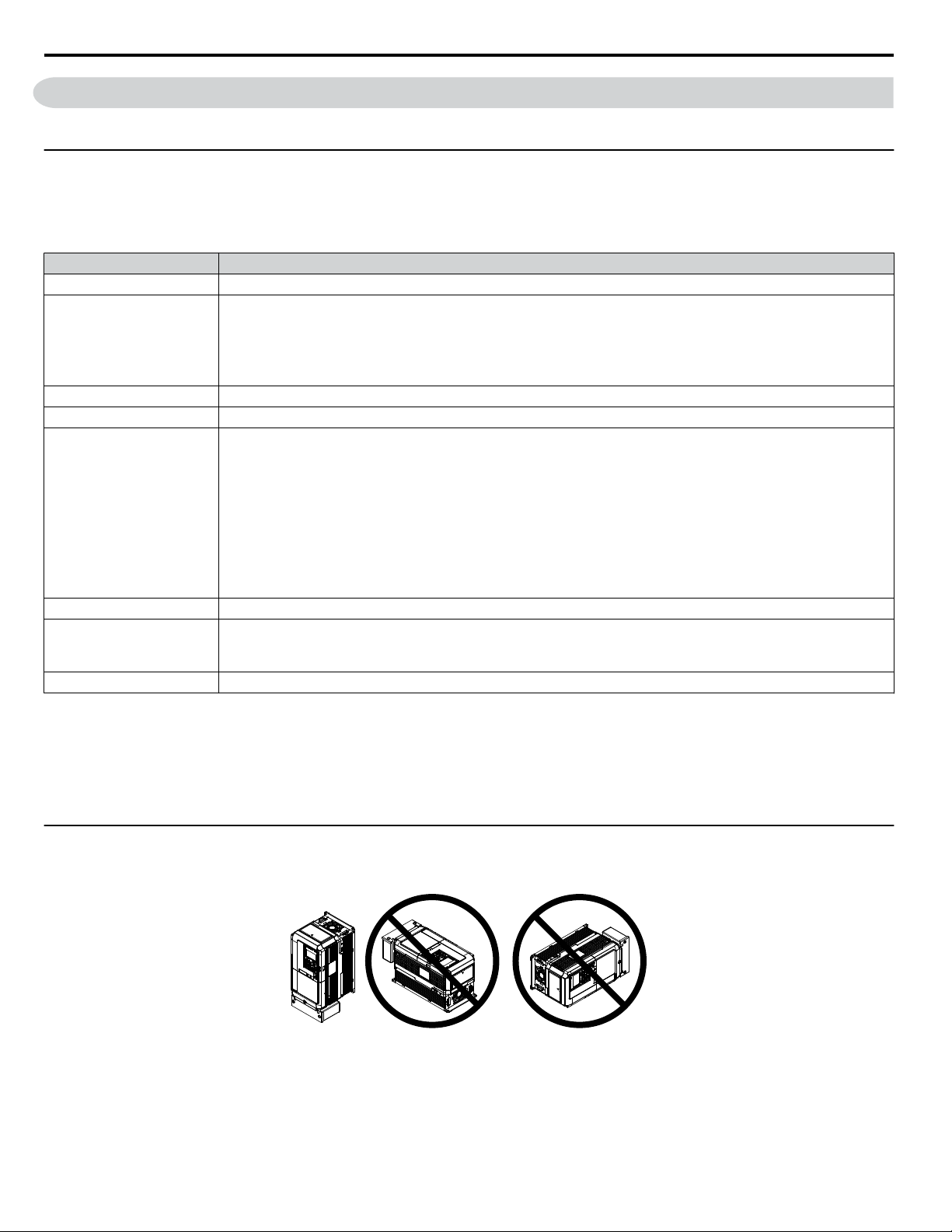
Installation Orientation and Spacing
Install the drive upright as illustrated in Figure 2.1 to maintain proper cooling.
Figure 2.1 Correct Installation Orientation
NOTICE:
26
Install the drive upright as specified in the manual. Failure to comply may damage the drive due to improper cooling.
YASKAWA ELECTRIC TOEP YAIP1U 01B YASKAWA AC Drive - P1000 Quick Start Guide
Page 27
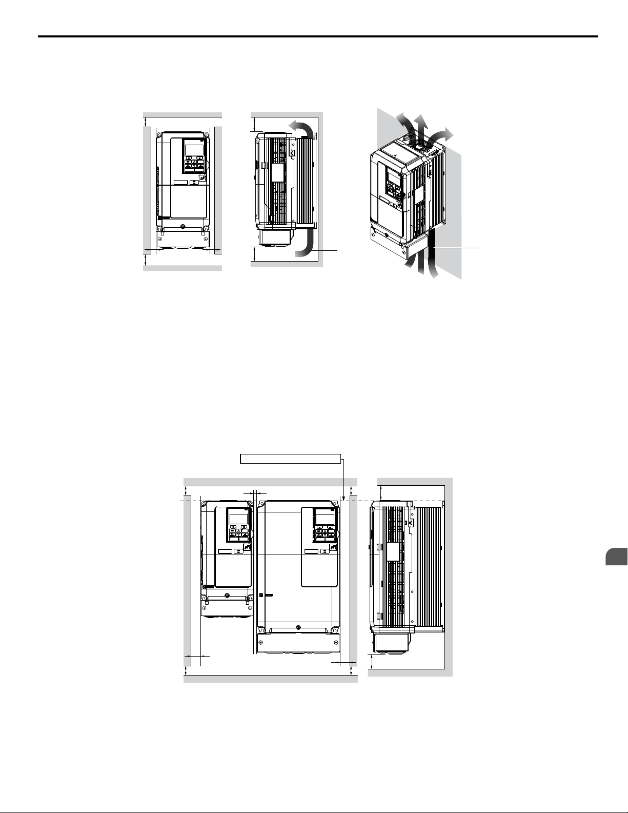
A
A
B B
Side Clearance Top/Bottom Clearance
C
C
D
D
A
A
A
A
B
C
B
Side Clearance
Line up the tops of the drives.
D
D
Top/Bottom Clearance
2.1 Mechanical Installation
Single Drive Installation
n
Figure 2.2 shows the installation distance required to maintain sufficient space for airflow and wiring. Install the heatsink
against a closed surface to avoid diverting cooling air around the heatsink.
A – 50 mm minimum
B – 30 mm minimum
C – 120 mm minimum
D – Airflow direction
Figure 2.2 Correct Installation Spacing
Note: IP20/NEMA Type 1 enclosure and IP00/Open Type enclosure models require the same amount of space above and below the drive for
installation.
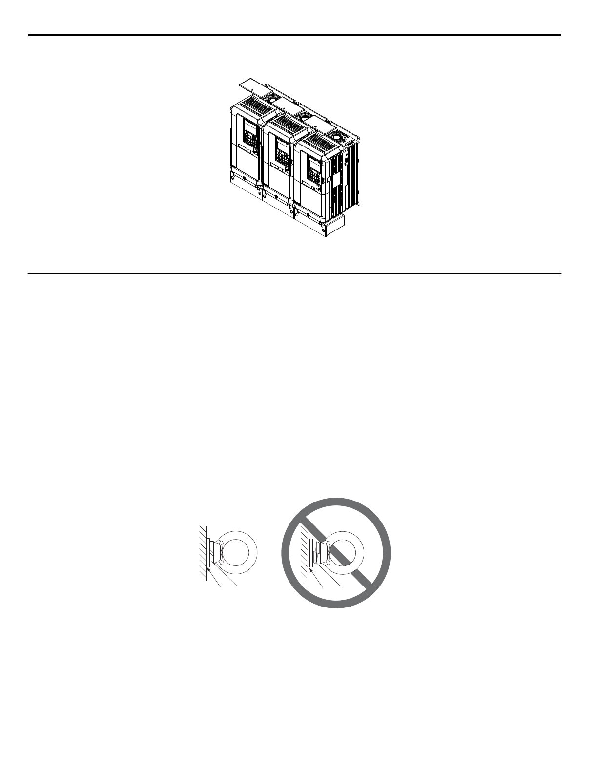
Multiple Drive Installation (Side-by-Side Installation)
n
Models 2A0004 to 2A0081, 4A0002 to 4A0044, and 5A0003 to 5A0032 can take advantage of Side-by-Side installation.
When installing multiple drives into the same enclosure panel, mount the drives according to Figure 2.2 and set L8-35,
Installation Method Selection, to 1 (Side-by-Side Mounting).
When mounting drives with the minimum clearance of 2 mm according to Figure 2.3, set parameter L8-35 to 1 while
considering derating. Refer to Parameter List on page 183 for details.
Mechanical Installation
2
A – 50 mm minimum
B – 30 mm minimum
Note: Align the tops of the drives when installing drives of different heights in the same enclosure panel. Leave space between the tops and bottoms
of stacked drives for easier cooling fan replacement.
YASKAWA ELECTRIC TOEP YAIP1U 01B YASKAWA AC Drive - P1000 Quick Start Guide
C – 2 mm minimum
D – 120 mm minimum
Figure 2.3 Space Between Drives (Side-by-Side Mounting)
27
Page 28
B
A
C
D
2.1 Mechanical Installation
Remove the top protective covers of all drives as shown in Figure 2.4 when mounting IP20/NEMA Type 1 enclosure drives
side-by-side. Refer to Top Protective Cover on page 54 to remove and reattach the top protective cover.
Figure 2.4 IP20/NEMA 1 Side-by-Side Mounting in Enclosure
u
Instructions on Installation Using the Eye Bolts
Eye bolts are used to install the drive or to temporarily lift the drive when replacing it. Using the eye bolts, the drive can be
installed in an enclosure panel or on a wall. Do not leave the drive suspended by the wires in a horizontal or vertical position
for long periods of time. Do not transport the drive over long distances. Read the following precautions and instructions before
installing the drive.
WARNING!
falling equipment.
Only use vertical suspension to temporarily lift the drive during installation to an enclosure panel. Do not use vertical suspension to transport
the drive.
Use screws to securely affix the drive front cover, terminal blocks, and other drive components prior to vertical suspension.
Do not subject the drive to vibration or impact greater than 1.96 m/s2 (0.2 G) while it is suspended by the wires.
Do not leave the drive unattended while it is suspended by the wires.
Do not attempt to flip the drive over while it is suspended by the wires.
Crush Hazard. Observe the following instructions and precautions. Failure to comply could result in serious injury or death from
Horizontal Suspension of Drive Models 2A0360, 2A0415, and 4A0250 to 4A0675
n
To make a wire hanger or frame for use when lifting the drive with a crane, lay the drive in a horizontal position and pass a
wire through the holes of the four eye bolts.
NOTICE:
damage the drive when lifted.
Damage to Equipment. When lifting the drive, confirm that the spring washer is fully closed. Failure to comply may deform or
A – No space between drive and washer
B – Spring washer fully closed
Figure 2.5 Spring Washer
C – Space between drive and washer
D – Spring washer open
28
YASKAWA ELECTRIC TOEP YAIP1U 01B YASKAWA AC Drive - P1000 Quick Start Guide
Page 29
Eye bolt
A
B
C
2.1 Mechanical Installation
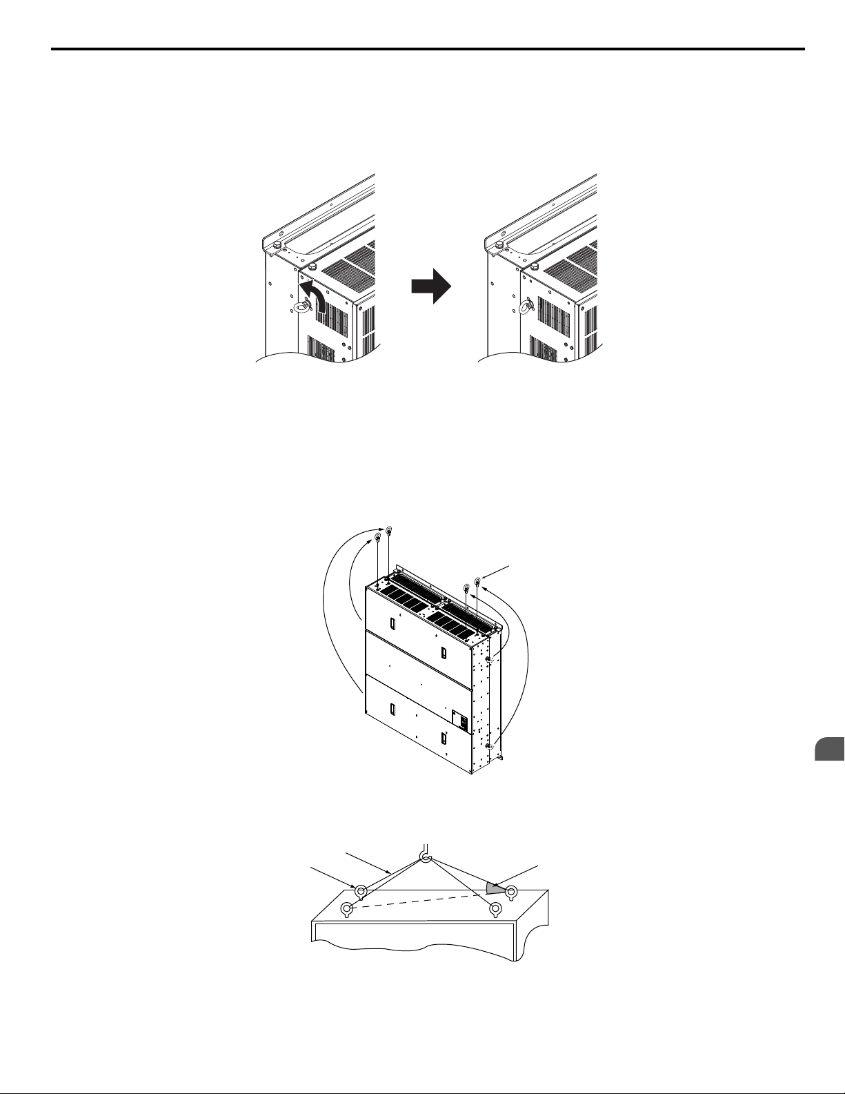
Vertical Suspension of Drive Models 2A0360, 2A0415, and 4A0250 to 4A1200
n
Models 2A0360, 2A0415, and 4A0250 to 4A0675
When vertical suspension of the drive is required in an enclosure panel, change the orientation of the eye bolts for these models
by turning the eye bolts counterclockwise 90 degrees.
Figure 2.6 Adjusting Angle of Eye Bolts
Models 4A0930 and 4A1200
When suspending models 4A0930 or 4A1200 with wires, follow the procedure described below.
WARNING!
maximum allowable load of the eye bolts cannot be guaranteed when the drive is suspended with the wires at angles less than 50°. Failure
to comply may result in serious injury or death from falling equipment.
1.
Crush Hazard. Use an adequate length of wire to ensure a 50° or wider suspension angle as illustrated in Figure 2.8. The
Remove the four eye bolts from the drive side panels and fix them securely on the top panel.
Figure 2.7 Eye Bolt Repositioning
Pass wire through the holes of all four eye bolts.
2.
YASKAWA ELECTRIC TOEP YAIP1U 01B YASKAWA AC Drive - P1000 Quick Start Guide
A – Eye bolt
B – Wires
Figure 2.8 Suspension Wire Angle Example
Mechanical Installation
2
C – Suspending angle: 50° or greater
29
Page 30

2.1 Mechanical Installation
Gradually take up the slack in the wires and hoist the drive after the wires are stretched tight.
3.
Lower the drive when ready to install in the enclosure panel. Stop lowering the drive when it is near the floor then
4.
begin lowering the drive again very slowly until the drive is placed correctly.
30
YASKAWA ELECTRIC TOEP YAIP1U 01B YASKAWA AC Drive - P1000 Quick Start Guide
Page 31

W1
4-d
H1
H
H0
H2
H3
W
Max.W2
D
D1
t2
t1
Figure 2Figure 1
W1
H4
H
H0
H1
H3
H2
D
D1
t1
4-d
W
Max.W2
2.1 Mechanical Installation
IP20/NEMA Type 1 Enclosure Drives
n
Note: Removing the top protective cover or bottom conduit bracket from an IP20/NEMA Type 1 enclosure drive voids NEMA Type 1 protection
while maintaining IP20 conformity.
Table 2.2 Dimensions for IP20/NEMA Type 1 Enclosure: 200 V Class
Dimensions mm (in)
260
(10.24)
(10.24)
(10.24)
(10.24)
(10.24)
(10.24)
(10.24)
(10.24)
(10.24)
(11.81)
(13.78)
(13.78)
(15.75)
(17.72)
(21.65)
(21.65)
248
(9.76)6(0.24)40(1.57)
260
248
(9.76)6(0.24)40(1.57)
260
248
(9.76)6(0.24)40(1.57)
260
248
(9.76)6(0.24)40(1.57)
260
248
(9.76)6(0.24)40(1.57)
260
248
(9.76)6(0.24)40(1.57)
260
248
(9.76)6(0.24)40(1.57)
260
248
(9.76)6(0.24)40(1.57)
260
248
(9.76)6(0.24)40(1.57)
300
284
(11.18)
350
335
(13.19)
350
335
(13.19)
400
385
(15.16)
450
435
(17.13)
550
535
(21.06)
550
535
(21.06)
Figure
1
<1>
2
<1>
W H D W1 W2 H0 H1 H2 H3 H4 D1 t1 t2 d
140
(5.51)
140
(5.51)
140
(5.51)
140
(5.51)
140
(5.51)
140
(5.51)
140
(5.51)
140
(5.51)
140
(5.51)
180
(7.09)
220
(8.66)
220
(8.66)
254
(10.00)
279
(10.98)
329
(12.95)
329
(12.95)
300
(11.81)
300
(11.81)
300
(11.81)
300
(11.81)
300
(11.81)
300
(11.81)
300
(11.81)
300
(11.81)
300
(11.81)
340
(13.39)
400
(15.75)
400
(15.75)
534
(21.02)
614
(24.17)
730
(28.74)
730
(28.74)
147
(5.79)
147
(5.79)
147
(5.79)
147
(5.79)
147
(5.79)
164
(6.46)
164
(6.46)
167
(6.57)
167
(6.57)
187
(7.36)
197
(7.76)
197
(7.76)
258
(10.16)
258
(10.16)
283
(11.14)
283
(11.14)
122
(4.80)
122
(4.80)
122
(4.80)
122
(4.80)
122
(4.80)
122
(4.80)
122
(4.80)
122
(4.80)
122
(4.80)
160
(6.30)
192
(7.56)
192
(7.56)
195
(7.68)
220
(8.66)
260
(10.24)
260
(10.24)
–
–
–
–
–
–
–
–
–
–
–
–
7.9
(0.31)
7.9
(0.31)
7.9
(0.31)
7.9
(0.31)
Drive Model
2A0004F
2A0006F
2A0008F
2A0010F
2A0012F
2A0018F
2A0021F
2A0030F
2A0040F
2A0056F
2A0069F
2A0081F
2A0110F
2A0138F
2A0169F
2A0211F
YASKAWA ELECTRIC TOEP YAIP1U 01B YASKAWA AC Drive - P1000 Quick Start Guide
7.9
(0.31)40(1.57)
7.9
(0.31)50(1.97)
7.9
(0.31)50(1.97)
7.7
134
(0.30)
(5.28)
7.7
7.7
7.7
164
(6.46)
180
(7.09)
180
(7.09)
(0.30)
(0.30)
(0.30)
1.5
(0.06)38(1.50)5(0.20)
1.5
(0.06)38(1.50)5(0.20)
1.5
(0.06)38(1.50)5(0.20)
1.5
(0.06)38(1.50)5(0.20)
1.5
(0.06)38(1.50)5(0.20)
1.5
(0.06)55(2.17)5(0.20)
1.5
(0.06)55(2.17)5(0.20)
1.5
(0.06)55(2.17)5(0.20)
1.5
(0.06)55(2.17)5(0.20)
1.5
(0.06)75(2.95)5(0.20)
1.5
(0.06)78(3.07)5(0.20)
1.5
(0.06)78(3.07)5(0.20)
1.5
(0.06)
100
(3.94)
100
–
(3.94)
110
–
(4.33)
110
–
(4.33)
Wt. kg
(lb)
– M5
– M5
– M5
– M5
– M5
– M5
– M5
– M5
– M5
– M5
– M6
– M6
2.2
2.2
2.2
2.2
2.286
(0.09)
2.286
(0.09)
2.286
(0.09)
2.286
(0.09)
(0.09)
(0.09)
(0.09)
(0.09)
M6
M6
M6
M6
3.3
(7.3)
3.3
(7.3)
3.4
(7.5)
3.4
(7.5)
3.4
(7.5)
3.8
(8.2)
3.8
(8.2)
4.2
(9.3)
4.2
(9.3)
5.9
(13.0)
9
(20.1)
10
(22.0)
23
(50.7)
28
(61.7)
41
(90.4)
42
(92.6)
Mechanical Installation
2
31
Page 32

2.1 Mechanical Installation
Drive Model Figure
Dimensions below are the dimensions of IP00/Open Type models after customer installation of the appropriate IP20/NEMA Type 1 Kit.
2A0250A
2A0312A
2A0360A
2
Dimensions mm (in)
W H D W1 W2 H0 H1 H2 H3 H4 D1 t1 t2 d
456
960
330
(17.95)
456
(17.95)
194
(19.84)
(37.80)
(12.99)
960
(37.80)
1168
(45.98)35(13.78)
330
(12.99)
325
(12.80)
325
(12.80)
370
(14.57)
7.9
(0.31)28(27.76)
7.9
(0.31)28(27.76)
7.9
(0.31)
800
(31.50)
680
(26.77)12(0.49)
680
(26.77)12(0.49)
773
(30.43)13(0.51)
255
(10.04)
255
(10.04)
368
(14.49)
130
–
(5.12)
130
–
(5.12)
130
–
(5.12)
3.3
(0.13)
3.3
(0.13)
4.6
(0.18)
3.3
(0.13)
3.30
(0.13)
4.6
(0.18)
M10
M10
M12
Wt. kg
(lb)
83
(183.0)
88
(194.0)
108
(238.1)
<1> Removing the top protective cover from a IP20/NEMA Type 1 enclosure drive voids NEMA Type 1 protection while retaining IP20 conformity.
Table 2.3 Dimensions for IP20/NEMA Type 1 Enclosure: 400 V Class
Drive Model
4A0002F
4A0004F
4A0005F
4A0007F
4A0009F
4A0011F
4A0018F
4A0023F
4A0031F
4A0038F
4A0044F
4A0058F
4A0072F
4A0088F
4A0103F
4A0139F
4A0165F
4A0208A
4A0250A
4A0296A
4A0362A
Figure
1
<1>
2
<1>
Dimensions below are the dimensions of IP00/Open Type models after customer installation of the appropriate IP20/NEMA Type 1 Kit.
2
W H D W1 W2 H0 H1 H2 H3 H4 D1 t1 t2 d
140
300
147
(5.51)
140
(5.51)
140
(5.51)
140
(5.51)
140
(5.51)
140
(5.51)
140
(5.51)
140
(5.51)
180
(7.09)
180
(7.09)
220
(8.66)
254
(10.00)
279
(10.98)
329
(12.95)
329
(12.95)
329
(12.95)
329
(12.95)
456
(17.95)
194
(19.84)
194
(19.84)
194
(19.84)
(11.81)
(11.81)
(11.81)
(11.81)
(11.81)
(11.81)
(11.81)
(11.81)
(13.39)
(13.39)
(15.75)
(18.31)
(20.28)
(24.80)
(24.80)
(28.74)
(28.74)
(37.80)
(45.98)35(13.78)
(45.98)35(13.78)
(45.98)35(13.78)
300
300
300
300
300
300
300
340
340
400
465
515
630
630
730
730
960
1168
1168
1168
(5.79)
147
(5.79)
147
(5.79)
164
(6.46)
164
(6.46)
164
(6.46)
167
(6.57)
167
(6.57)
167
(6.57)
187
(7.36)
197
(7.76)
258
(10.16)
258
(10.16)
258
(10.16)
258
(10.16)
283
(11.14)
283
(11.14)
330
(12.99)
122
(4.80)
122
(4.80)
122
(4.80)
122
(4.80)
122
(4.80)
122
(4.80)
122
(4.80)
122
(4.80)
160
(6.30)
160
(6.30)
195
(7.68)
195
(7.68)
220
(8.66)
260
(10.24)
260
(10.24)
260
(10.24)
260
(10.24)
325
(12.80)
370
(14.57)
370
(14.57)
370
(14.57)
–
–
–
–
–
–
–
–
–
–
–
7.9
(0.31)
7.9
(0.31)
7.9
(0.31)
7.9
(0.31)
7.9
(0.31)
7.9
(0.31)
7.9
(0.31)28(27.76)
7.9
(0.31)
7.9
(0.31)
7.9
(0.31)
Dimensions mm (in)
260
(10.24)
(10.24)
(10.24)
(10.24)
(10.24)
(10.24)
(10.24)
(10.24)
(11.81)
(11.81)
(13.78)
(15.75)
(17.72)
(20.08)
(20.08)
(21.65)
(21.65)
(31.50)
(31.50)
(31.50)
248
(9.76)6(0.24)40(1.57)
260
248
(9.76)6(0.24)40(1.57)
260
248
(9.76)6(0.24)40(1.57)
260
248
(9.76)6(0.24)40(1.57)
260
248
(9.76)6(0.24)40(1.57)
260
248
(9.76)6(0.24)40(1.57)
260
248
(9.76)6(0.24)40(1.57)
260
248
(9.76)6(0.24)40(1.57)
300
284
(11.18)
300
284
(11.18)
35
335
(13.19)
400
385
(15.16)
450
435
(17.13)
509
495
(19.49)
509
495
(19.49)
550
535
(21.06)
550
535
(21.06)
680
(26.77)12(0.49)
800
773
(30.43)13(0.51)
800
773
(30.43)13(0.51)
800
773
(30.43)13(0.51)
7.9
(0.31)40(1.57)
7.9
(0.31)40(1.57)
7.9
(0.31)50(1.97)
7.7
(0.30)65(2.56)
7.7
(0.30)65(2.56)
7.7
7.7
7.7
7.7
120
(4.72)
120
(4.72)
180
(7.09)
180
(7.09)
255
(10.04)
368
(14.49)
368
(14.49)
368
(14.49)
(0.30)
(0.30)
(0.30)
(0.30)
1.5
(0.06)38(1.50)5(0.20)
1.5
(0.06)38(1.50)5(0.20)
1.5
(0.06)38(1.50)5(0.20)
1.5
(0.06)55(2.17)5(0.20)
1.5
(0.06)55(2.17)5(0.20)
1.5
(0.06)55(2.17)5(0.20)
1.5
(0.06)55(2.17)5(0.20)
1.5
(0.06)55(2.17)5(0.20)
1.5
(0.06)55(2.17)5(0.20)
1.5
(0.06)75(2.95)5(0.20)
1.5
(0.06)78(3.07)5(0.20)
100
–
(3.94)
100
–
(3.94)
105
–
(4.13)
105
–
(4.13)
110
–
(4.33)
110
–
(4.33)
130
–
(5.12)
130
–
(5.12)
130
–
(5.12)
130
–
(5.12)
2.2
(0.09)
2.2
(0.09)
2.2
(0.09)
2.2
(0.09)
2.2
(0.09)
2.2
(0.09)
3.3
(0.13)
4.6
(0.18)
4.6
(0.18)
4.6
(0.18)
– M5
– M5
– M5
– M5
– M5
– M5
– M5
– M5
– M5
– M5
– M6
2.2
(0.09)
2.2
(0.09)
3.3
(0.13)
3.3
(0.13)
2.2
(0.09)
2.2
(0.09)
3.3
(0.13)
4.6
(0.18)
4.6
(0.18)
4.6
(0.18)
M6
M6
M6
M6
M6
M6
M10
M12
M12
M12
Wt. kg
(lb)
3.4
(7.5)
3.4
(7.5)
3.4
(7.5)
3.6
(7.9)
3.8
(8.2)
3.8
(8.2)
4.0
(9.0)
4.0
(9.0)
5.8
(12.6)
6.0
(13.2)
8.8
(19.2)
23
(50.7)
27
(59.5)
39
(86.0)
39
(86.0)
45
(99.2)
46
(101.4)
87
(191.8)
106
(233.7)
112
(246.9)
117
(257.9)
<1> Removing the top protective cover from a IP20/NEMA Type 1 enclosure drive voids NEMA Type 1 protection while retaining IP20 conformity.
32
YASKAWA ELECTRIC TOEP YAIP1U 01B YASKAWA AC Drive - P1000 Quick Start Guide
Page 33

2.1 Mechanical Installation
Table 2.4 Dimensions for IP20/NEMA Type 1 Enclosure: 600 V Class
Drive Model Figure
5A0003F
5A0004F
5A0006F
5A0009F
5A0011F
5A0017F
5A0022F
5A0027F
5A0032F
5A0041F
5A0052F
5A0062F
5A0077F
5A0099F
5A0125A
5A0145A
5A0192A
5A0242A
1
<1>
2
Dimensions below are the dimensions of IP00/Open Type models after customer installation of the appropriate IP20/NEMA Type 1 Kit.
2
W H D W1 W2 H0 H1 H2 H3 H4 D1 t1 t2 d
140
(5.51)
140
(5.51)
140
(5.51)
140
(5.51)
140
(5.51)
180
(7.09)
180
(7.09)
220
(8.66)
220
(8.66)
279
(10.98)
279
(10.98)
329
(12.95)
329
(12.95)
329
(12.95)
456
(17.95)
456
(17.95)
194
(19.84)
194
(19.84)
300
300
300
300
300
340
340
400
400
515
515
730
730
730
960
960
147
(5.79)
147
(5.79)
164
(6.46)
164
(6.46)
167
(6.57)
187
(7.36)
187
(7.36)
197
(7.76)
197
(7.76)
258
(10.16)
258
(10.16)
283
(11.14)
283
(11.14)
283
(11.14)
330
(12.99)
330
(12.99)
(11.81)
(11.81)
(11.81)
(11.81)
(11.81)
(13.39)
(13.39)
(15.75)
(15.75)
(20.28)
(20.28)
(28.74)
(28.74)
(28.74)
(37.80)
(37.80)
1168
(45.98)35(13.78)
1168
(45.98)35(13.78)
122
(4.80)
122
(4.80)
122
(4.80)
122
(4.80)
122
(4.80)
160
(6.30)
160
(6.30)
192
(7.56)
192
(7.56)
220
(8.66)
220
(8.66)
260
(10.24)
260
(10.24)
260
(10.24)
325
(12.80)
325
(12.80)
370
(14.57)
370
(14.57)
–
–
–
–
–
–
–
–
–
7.9
(0.31)
7.9
(0.31)
7.9
(0.31)
7.9
(0.31)
7.9
(0.31)
7.9
(0.31)28(27.76)
7.9
(0.31)28(27.76)
7.9
(0.31)
7.9
(0.31)
Dimensions mm (in)
260
(10.24)
260
(10.24)
260
(10.24)
260
(10.24)
260
(10.24)
300
(11.81)
300
(11.81)
(13.78)
(13.78)
450
(17.72)
450
(17.72)
550
(21.65)
550
(21.65)
550
(21.65)
800
(31.50)
800
(31.50)
248
(9.76)6(0.24)40(1.57)
248
(9.76)6(0.24)40(1.57)
248
(9.76)6(0.24)40(1.57)
248
(9.76)6(0.24)40(1.57)
248
(9.76)6(0.24)40(1.57)
284
(11.18)
284
(11.18)
35
335
(13.19)
35
335
(13.19)
435
(17.13)
435
(17.13)
535
(21.06)
535
(21.06)
535
(21.06)
680
(26.77)12(0.49)
680
(26.77)12(0.49)
773
(30.43)13(0.51)
773
(30.43)13(0.51)
7.9
(0.31)40(1.57)
7.9
(0.31)40(1.57)
7.9
(0.31)50(1.97)
7.9
(0.31)50(1.97)
7.7
(0.30)65(2.56)
7.7
(0.30)65(2.56)
7.7
7.7
7.7
180
(7.09)
180
(7.09)
180
(7.09)
255
(10.04)
255
(10.04)
368
(14.49)
368
(14.49)
(0.30)
(0.30)
(0.30)
1.5
(0.06)38(1.50)5(0.20)
1.5
(0.06)38(1.50)5(0.20)
1.5
(0.06)55(2.17)5(0.20)
1.5
(0.06)55(2.17)5(0.20)
1.5
(0.06)55(2.17)5(0.20)
1.5
(0.06)75(2.95)5(0.20)
1.5
(0.06)75(2.95)5(0.20)
1.5
(0.06)78(3.07)5(0.20)
1.5
(0.06)78(3.07)5(0.20)
100
–
(3.94)
100
–
(3.94)
110
–
(4.33)
110
–
(4.33)
110
–
(4.33)
130
–
(5.12)
130
–
(5.12)
130
–
(5.12)
130
–
(5.12)
2.2
(0.09)
2.2
(0.09)
2.2
(0.09)
2.2
(0.09)
2.2
(0.09)
3.3
(0.13)
3.3
(0.13)
4.6
(0.18)
4.6
(0.18)
– M5
– M5
– M5
– M5
– M5
– M5
– M5
– M6
– M6
2.2
(0.09)
2.2
(0.09)
2.2
(0.09)
2.2
(0.09)
2.2
(0.09)
3.3
(0.13)
3.3
(0.13)
4.6
(0.18)
4.6
(0.18)
<1> Removing the top protective cover or bottom conduit bracket from an IP20/NEMA Type 1 enclosure drive voids NEMA Type 1 protection while
maintaining IP20 conformity.
M6
M6
M6
M6
M6
M10
M10
M12
M12
Wt. kg
(lb)
3.4
(7.5)
3.4
(7.5)
3.8
(8.2)
3.8
(8.2)
4.0
(9.0)
6.0
(13.2)
6.0
(13.2)
8.8
(19.2)
8.8
(19.2)
27
(59.5)
27
(59.5)
45
(99.2)
45
(99.2)
45
(99.2)
87
(191.8)
87
(191.8)
106
(233.7)
117
(257.9)
Mechanical Installation
YASKAWA ELECTRIC TOEP YAIP1U 01B YASKAWA AC Drive - P1000 Quick Start Guide
2
33
Page 34

2.1 Mechanical Installation
IP20/NEMA Type 1 Enclosure Conduit Bracket Dimensions
W
W W
Ød6
W
W1
W1
Ød5
Ød6
W W
W1 W1
W2 W2
Ød5
Ød6
Ød5
W1 W1
Figure 1
W
W2 W2
W
W1 W1
Figure 4
D2
D1
D3
D
Ød7
D1
D2
D3
D
Ød7
D1
D2
D D3
Figure 2
Figure 3
D3D
Ød5
Ød6
W W
W1 W1
W2 W2
D1
D2
Ød5
Ød6
Ød7
D3
D
W W
W1 W1
D1
D2
Ød5
Ød6
D3
D
D2
Ød7
D1
Figure 6
Figure 5
Drive Model
2A0004F
2A0006F
2A0008F
2A0010F
2A0012F
W W
W2
W1 W4
W3 W3
Figure 7
Figure
1
Ød5
Ød6
Ød7
D4
D
W W
W1 W1
W2 W2
D2
D1
D3
W3 W3
Ød5
Ød6
Ød7
D1
D2
D3
D
W W
W1 W1
W4 W4
W3
W2W2
Figure 9
Ød5
Ød7
Ød6
D1
D2
D3
D
Figure 8
Table 2.5 Conduit Bracket Dimensions for IP20/NEMA Type 1
Dimensions mm (in)
W D W1 W2 W3 W4 D1 D2 D3 D4 d5 d6 d7
200 V Class
43
(1.7)
43
(1.7)
43
(1.7)
43
(1.7)
43
(1.7)
38
(1.5)38(1.5)
38
(1.5)38(1.5)
38
(1.5)38(1.5)
38
(1.5)38(1.5)
56
(2.2)38(1.5)
– – –
– – –
– – –
– – –
– – –
41
(1.6)71(2.8)79(3.1)
41
(1.6)71(2.8)79(3.1)
41
(1.6)71(2.8)79(3.1)
41
(1.6)71(2.8)79(3.1)
41
(1.6)71(2.8)79(3.1)
–
–
– – – –
–
–
Diameter mm (in)
23
(0.9)36(1.4)
23
(0.9)36(1.4)
23
(0.9)36(1.4)
23
(0.9)36(1.4)
–
–
–
–
34
YASKAWA ELECTRIC TOEP YAIP1U 01B YASKAWA AC Drive - P1000 Quick Start Guide
Page 35

2.1 Mechanical Installation
Drive Model Figure
2A0018F
2A0021F
2A0030F
2A0040F
2A0056F
2A0069F
2A0081F
2A0110F 4
2A0138F 5
2A0169F
2A0211F
2A0250A
2A0312A
2A0360A 9
4A0002F
4A0004F
4A0005F
4A0007F
4A0009F
4A0011F
4A0018F
4A0023F
4A0031F
4A0038F
4A0044F
4A0058F
4A0072F
4A0088F
4A0103F
2
7
8
1
2
3
6
Dimensions mm (in)
W D W1 W2 W3 W4 D1 D2 D3 D4 d5 d6 d7
43
(1.7)56(2.2)38(1.5)
43
(1.7)56(2.2)38(1.5)
43
(1.7)56(2.2)38(1.5)
25
(1.0)76(3.0)56(2.2)
25
(1.0)76(3.0)56(2.2)
28
(1.1)79(3.1)64(2.5)
28
(1.1)79(3.1)64(2.5)
86
(3.4)99(3.9)38(1.5)23(0.9)
99
(3.9)99(3.9)89(3.5)41(1.6)
111
(4.4)
111
(4.4)
175
(6.9)
175
(6.9)
191
(7.5)
43
(1.7)38(1.5)38(1.5)
43
(1.7)38(1.5)38(1.5)
43
(1.7)38(1.5)38(1.5)
43
(1.7)56(2.2)38(1.5)
43
(1.7)56(2.2)38(1.5)
43
(1.7)56(2.2)38(1.5)
43
(1.7)56(2.2)38(1.5)
25
(1.0)76(3.0)56(2.2)
25
(1.0)76(3.0)56(2.2)
28
(1.1)79(3.1)64(2.5)
28
(1.1)79(3.1)64(2.5)
86
(3.4)99(3.9)38(1.5)23(0.9)
89
(3.5)99(3.9)41(1.6)23(0.9)
84
(3.3)
84
(3.3)
109
(4.3)56(2.2)15(0.6)30(1.2)66(2.6)
109
(4.3)56(2.2)15(0.6)30(1.2)66(2.6)
130
(5.1)91(3.6)84(3.3)25(1.0)
130
(5.1)91(3.6)84(3.3)25(1.0)
130
(5.1)
104
(4.1)23(0.9)
104
(4.1)23(0.9)
104
(4.1)30(1.2)28(1.1)71(2.8)
– – –
– – –
– – –
– – –
– – –
– – –
– – –
– – –
– – –
– – –
– – –
– – –
– – –
– – –
– – –
– – –
– – –
– – –
– – –
– – –
– –
– –
–
–
400 V Class
– –
– –
41
(1.6)71(2.8)79(3.1)
41
(1.6)71(2.8)79(3.1)
41
(1.6)71(2.8)79(3.1)
48
(1.9)84(3.3)53(2.1)
48
(1.9)84(3.3)53(2.1)
51
(2.0)86(3.4)56(2.2)
51
(2.0)86(3.4)56(2.2)
99
(3.9)43(1.7)25(1.0)
99
(3.9)43(1.7)25(1.0)
119
(4.7)
119
(4.7)
137
(5.4)51(2.0)41(1.6)
137
(5.4)51(2.0)41(1.6)
157
(6.2)71(2.8)51(2.0)
41
(1.6)71(2.8)79(3.1)
41
(1.6)71(2.8)79(3.1)
41
(1.6)71(2.8)79(3.1)
41
(1.6)71(2.8)79(3.1)
41
(1.6)71(2.8)79(3.1)
41
(1.6)71(2.8)79(3.1)
41
(1.6)71(2.8)79(3.1)
48
(1.9)84(3.3)53(2.1)
48
(1.9)84(3.3)53(2.1)
51
(2.0)86(3.4)56(2.2)
51
(2.0)86(3.4)56(2.2)
99
(3.9)43(1.7)25(1.0)
99
(3.9)43(1.7)25(1.0)
99
(3.9)66(2.6)25(1.0)
99
(3.9)66(2.6)25(1.0)
109
(4.3)53(2.1)41(1.6)51(2.0)36(1.4)61(2.4)
109
(4.3)53(2.1)41(1.6)51(2.0)36(1.4)61(2.4)
–
–
–
–
–
–
–
–
–
–
–
–
–
–
–
–
–
–
–
–
–
–
–
–
–
–
–
Diameter mm (in)
36
(1.4)23(0.9)43(1.7)
36
(1.4)23(0.9)43(1.7)
36
(1.4)23(0.9)43(1.7)
36
(1.4)23(0.9)43(1.7)
36
(1.4)23(0.9)43(1.7)
36
(1.4)23(0.9)43(1.7)
36
(1.4)23(0.9)43(1.7)
61
(2.4)28(1.1)
51
(2.0)61(2.4)28(1.1)
51
(2.0)61(2.4)36(1.4)
51
(2.0)61(2.4)36(1.4)
51
(2.0)61(2.4)43(1.7)
23
(0.9)36(1.4)
23
(0.9)36(1.4)
23
(0.9)36(1.4)
23
(0.9)36(1.4)
23
(0.9)36(1.4)
23
(0.9)36(1.4)
23
(0.9)36(1.4)
36
(1.4)23(0.9)43(1.7)
36
(1.4)23(0.9)43(1.7)
36
(1.4)23(0.9)43(1.7)
36
(1.4)23(0.9)43(1.7)
61
(2.4)28(1.1)51(2.0)
61
(2.4)28(1.1)51(2.0)
51
(2.0)61(2.4)28(1.1)
51
(2.0)61(2.4)28(1.1)
–
–
–
–
–
–
–
–
Mechanical Installation
2
YASKAWA ELECTRIC TOEP YAIP1U 01B YASKAWA AC Drive - P1000 Quick Start Guide
35
Page 36

2.1 Mechanical Installation
Drive Model Figure
4A0139F
7
4A0165F
4A0208A 8
4A0250A
4A0296A
4A0362A
5A0003F
5A0004F
5A0006F
5A0009F
5A0011F
5A0017F
5A0022F
5A0027F
5A0032F
5A0041F
5A0052F
5A0062F
5A0077F
5A0099F
5A0125A
5A0145A
5A0192A
5A0242A
9
1
2
3
7
8
9
Dimensions mm (in)
W D W1 W2 W3 W4 D1 D2 D3 D4 d5 d6 d7
111
(4.4)
111
(4.4)
175
(6.9)
191
(7.5)
191
(7.5)
191
(7.5)
43
(1.7)
43
(1.7)
43
(1.7)
43
(1.7)
43
(1.7)
25
(1.0)
25
(1.0)
28
(1.1)
28
(1.1)
89
(3.5)
89
(3.5)
111
(4.4)
111
(4.4)
111
(4.4)
175
(6.9)
175
(6.9)
191
(7.5)
191
(7.5)
109
(4.3)56(2.2)15(0.6)
109
(4.3)56(2.2)15(0.6)
130
(5.1)91(3.6)84(3.3)
130
(5.1)
130
(5.1)
130
(5.1)
38
(1.5)38(1.5)
38
(1.5)38(1.5)
56
(2.2)38(1.5)
56
(2.2)38(1.5)
56
(2.2)38(1.5)
76
(3.0)56(2.2)
76
(3.0)56(2.2)
79
(3.1)64(2.5)
79
(3.1)64(2.5)
99
(3.9)41(1.6)23(0.9)
99
(3.9)41(1.6)23(0.9)
109
(4.3)56(2.2)15(0.6)
109
(4.3)56(2.2)15(0.6)
109
(4.3)56(2.2)15(0.6)
130
(5.1)91(3.6)84(3.3)
130
(5.1)91(3.6)84(3.3)
130
(5.1)
130
(5.1)
104
(4.1)30(1.2)
104
(4.1)30(1.2)
104
(4.1)30(1.2)
– – –
– – –
– – –
– – –
– – –
– – –
– – –
– – –
– – –
104
(4.1)30(1.2)
104
(4.1)30(1.2)
30
(1.2)66(2.6)
30
(1.2)66(2.6)
25
(1.0)
28
(1.1)71(2.8)
28
(1.1)71(2.8)
28
(1.1)71(2.8)
600 V Class
– –
– –
30
(1.2)66(2.6)
30
(1.2)66(2.6)
30
(1.2)66(2.6)
25
(1.0)
25
(1.0)
28
(1.1)71(2.8)
28
(1.1)71(2.8)
119
(4.7)
119
(4.7)
137
–
(5.4)51(2.0)41(1.6)
157
(6.2)71(2.8)51(2.0)
157
(6.2)71(2.8)51(2.0)
157
(6.2)71(2.8)51(2.0)
41
(1.6)71(2.8)79(3.1)
41
(1.6)71(2.8)79(3.1)
41
(1.6)71(2.8)79(3.1)
41
(1.6)71(2.8)79(3.1)
41
(1.6)71(2.8)79(3.1)
48
(1.9)84(3.3)53(2.1)
48
(1.9)84(3.3)53(2.1)
51
(2.0)86(3.4)56(2.2)
51
(2.0)86(3.4)56(2.2)
99
(3.9)43(1.7)25(1.0)
99
(3.9)43(1.7)25(1.0)
119
(4.7)
119
(4.7)
119
(4.7)
137
–
(5.4)51(2.0)41(1.6)
137
–
(5.4)51(2.0)41(1.6)
157
(6.2)71(2.8)51(2.0)
157
(6.2)71(2.8)51(2.0)
109
(4.3)53(2.1)41(1.6)51(2.0)36(1.4)61(2.4)
109
(4.3)53(2.1)41(1.6)51(2.0)36(1.4)61(2.4)
–
–
–
–
–
–
–
–
–
–
–
–
–
–
–
109
(4.3)53(2.1)41(1.6)51(2.0)36(1.4)61(2.4)
109
(4.3)53(2.1)41(1.6)51(2.0)36(1.4)61(2.4)
109
(4.3)53(2.1)41(1.6)51(2.0)36(1.4)61(2.4)
–
–
–
–
Diameter mm (in)
51
(2.0)61(2.4)36(1.4)
51
(2.0)61(2.4)43(1.7)
51
(2.0)61(2.4)43(1.7)
51
(2.0)61(2.4)43(1.7)
23
(0.9)36(1.4)
23
(0.9)36(1.4)
23
(0.9)36(1.4)
23
(0.9)36(1.4)
23
(0.9)36(1.4)
36
(1.4)23(0.9)43(1.7)
36
(1.4)23(0.9)43(1.7)
36
(1.4)23(0.9)43(1.7)
36
(1.4)23(0.9)43(1.7)
61
(2.4)28(1.1)51(2.0)
61
(2.4)28(1.1)51(2.0)
51
(2.0)61(2.4)36(1.4)
51
(2.0)61(2.4)36(1.4)
51
(2.0)61(2.4)43(1.7)
51
(2.0)61(2.4)43(1.7)
–
–
–
–
–
Note: Removing the top protective cover or bottom conduit bracket from an IP20/NEMA Type 1 enclosure drive voids NEMA Type 1 protection
while maintaining IP20 conformity.
36
YASKAWA ELECTRIC TOEP YAIP1U 01B YASKAWA AC Drive - P1000 Quick Start Guide
Page 37

IP00/Open Type Enclosure Drives
n
W1
2.1 Mechanical Installation
W1
4-d
H
H1
t2
4-d
H
H1
t2
Drive
Model
2A0250A
<1>
Max W2
Figure
H2
Max W2
Figure 2
Figure 4
8-d
D
H1
H
H2
Max W2Max W2
Max W2
W3
W1
t1
H2
6-d
Max W2
Max W2
Figure 3
Figure 1
H
H1
H2
W
W3
W
D1
D
t2
t1
D1
D
Max W2
W
W1
W3 W3
W4
W
Table 2.6 Dimensions for IP00/Open Type Enclosure: 200 V Class
Dimensions mm (in)
W H D W1 W2 H1 H2 D1 t1 t2 d
450
(17.72)
705
(27.76)
330
(12.99)
325
(12.80)10(0.39)
680
(26.77)12(0.49)
130
(5.12)
3.3
(0.13)
3.3
(0.13)
t1
D1
t2
t1
D1
D
Wt. kg
(lb)
M10
76
(167.6)
Mechanical Installation
2A0312A
<1>
2A0360A
<1>
2A0415A
450
1
(17.72)
500
(19.69)
500
(19.69)
705
(27.76)
800
(31.50)
800
(31.50)
330
(12.99)
350
(13.78)
350
(13.78)
325
(12.80)10(0.39)
370
(14.57)10(0.39)
370
(14.57)10(0.39)
680
(26.77)12(0.49)
773
(30.43)13(0.51)
773
(30.43)13(0.51)
130
(5.12)
130
(5.12)
130
(5.12)
<1> Customers may convert these models to IP20/NEMA Type 1 enclosures using an IP20/NEMA Type 1 Kit.
YASKAWA ELECTRIC TOEP YAIP1U 01B YASKAWA AC Drive - P1000 Quick Start Guide
3.3
(0.13)
4.6
(0.18)
4.6
(0.18)
3.3
(0.13)
4.6
(0.18)
4.6
(0.18)
M10
M12
M12
80
(176.4)
98
(216.1)
99
(218.3)
2
37
Page 38

2.1 Mechanical Installation
Drive
Model
4A0208A
<1>
Figure
W H D W1 W2 W3 W4 H1 H2 D1 t1 t2 d
450
(17.72)
705
(27.76)
Table 2.7 Dimensions for IP00/Open Type Enclosure: 400 V Class
Dimensions mm (in)
330
(12.99)
325
(12.80)10(0.39)
– –
680
(26.77)
12.4
(0.49)
130
(5.12)
3.3
(0.13)
3.3
(0.13)
M10
Wt. kg
(lb)
79
(174.2)
4A0250A
<1>
4A0296A
<1>
4A0362A
<1>
4A0414A 2
4A0515A
4A0675A
4A0930A 4
4A1200A 4
500
(19.69)
1
3
500
(19.69)
500
(19.69)
500
(19.69)
670
(26.38)
670
(26.38)
1250
(49.21)
1250
(49.21)
800
(31.50)
800
(31.50)
800
(31.50)
950
(37.40)
1140
(44.88)
1140
(44.88)
1380
(54.33)
1380
(54.33)
350
(13.78)
350
(13.78)
350
(13.78)
370
(14.57)
370
(14.57)
370
(14.57)
370
(14.57)
370
(14.57)
370
(14.57)10(0.39)
370
(14.57)10(0.39)
370
(14.57)10(0.39)
370
(14.57)
440
(17.32)6(0.24)
440
(17.32)6(0.24)
1110
(43.70)6(0.24)
1110
(43.70)6(0.24)
7.9
(0.31)
– –
– –
– –
– –
220
(8.66)
220
(8.66)
330
(13.00)
330
(13.00)
–
–
440
(17.32)
440
(17.32)
773
(30.43)13(0.51)
773
(30.43)13(0.51)
773
(30.43)13(0.51)
923
(36.34)13(0.51)
1110
(43.70)15(0.59)
1110
(43.70)15(0.59)
1345
(52.95)15(0.59)
1345
(52.95)15(0.59)
130
(5.12)
130
(5.12)
130
(5.12)
135
(5.31)
150
(5.91)
150
(5.91)
150
(5.91)
150
(5.91)
<1> Customers may convert these models to IP20/NEMA Type 1 enclosures using an IP20/NEMA Type 1 Kit.
Table 2.8 Dimensions for IP00/Open Type Enclosure: 600 V Class
Drive
Model
5A0125A
<1>
5A0145A
<1>
5A0192A
<1>
Figure
1
W H D W1 W2 W3 W4 H1 H2 D1 t1 t2 d
450
(17.72)
450
(17.72)
500
(19.69)
705
(27.76)
705
(27.76)
800
(31.50)
330
(12.99)
330
(12.99)
350
(13.78)
325
(12.80)10(0.39)
325
(12.80)10(0.39)
370
(14.57)10(0.39)
Dimensions mm (in)
– –
– –
– –
680
(26.77)
680
(26.77)
773
(30.43)13(0.51)
12.4
(0.49)
12.4
(0.49)
130
(5.12)
130
(5.12)
130
(5.12)
4.6
(0.18)
4.6
(0.18)
4.6
(0.18)
4.6
(0.18)
4.6
(0.18)
4.6
(0.18)
4.6
(0.18)
4.6
(0.18)
3.3
(0.13)
3.3
(0.13)
4.6
(0.18)
4.6
(0.18)
4.6
(0.18)
4.6
(0.18)
4.6
(0.18)
4.6
(0.18)
4.6
(0.18)
4.6
(0.18)
4.6
(0.18)
3.3
(0.13)
3.3
(0.13)
4.6
(0.18)
M12
M12
M12
M12
M12
M12
M12
M12
M10
M10
M12
96
(211.6)
102
(224.9)
107
(235.9)
125
(275.6)
216
(476.2)
221
(487.2)
545
(1201.5)
555
(1223.6)
Wt. kg
(lb)
79
(174.2)
79
(174.2)
107
(235.9)
5A0242A
<1>
500
(19.69)
800
(31.50)
350
(13.78)
370
(14.57)10(0.39)
– –
773
(30.43)13(0.51)
130
(5.12)
<1> Customers may convert these models to IP20/NEMA Type 1 enclosures using an IP20/NEMA Type 1 Kit.
4.6
(0.18)
4.6
(0.18)
M12
107
(235.9)
38
YASKAWA ELECTRIC TOEP YAIP1U 01B YASKAWA AC Drive - P1000 Quick Start Guide
Page 39

2.1 Mechanical Installation
IP20/NEMA Type 1 Kit Selection
Customers may convert IP00/Open Type models to IP20/NEMA Type 1 enclosures. Refer to Table 2.9 to select the appropriate
IP20/NEMA Type 1 Kit when performing the conversion.
Contact a Yaskawa representative for IP20/NEMA Type 1 Kit availability for IP00/Open Type models not listed.
Table 2.9 IP20/NEMA Type 1 Kit Selection
IP00/Open Type
Drive Model
2A0250A
2A0312A
2A0360A
4A0208A
4A0250A
4A0362A
5A0125A
5A0145A
5A0192A
5A0242A
IP20/NEMA Type 1 Kit Code Comments
100-054-503
Refer to IP20/NEMA Type 1 Enclosure
100-054-5044A0296A
100-054-503
100-054-504
Drives on page 31 for drive dimensions with the
IP20/NEMA Type 1 Kit installed.
YASKAWA ELECTRIC TOEP YAIP1U 01B YASKAWA AC Drive - P1000 Quick Start Guide
Mechanical Installation
2
39
Page 40

2.1 Mechanical Installation
This Page Intentionally Blank
40
YASKAWA ELECTRIC TOEP YAIP1U 01B YASKAWA AC Drive - P1000 Quick Start Guide
Page 41

3
Electrical Installation
This chapter explains proper procedures for wiring the control circuit terminals, motor, and power
supply.
3.1 STANDARD CONNECTION DIAGRAM.................................................................42
3.2 MAIN CIRCUIT CONNECTION DIAGRAM.............................................................45
3.3 TERMINAL COVER................................................................................................49
3.4 DIGITAL OPERATOR AND FRONT COVER.........................................................51
3.5 TOP PROTECTIVE COVER...................................................................................54
3.6 MAIN CIRCUIT WIRING.........................................................................................55
3.7 CONTROL CIRCUIT WIRING.................................................................................66
3.8 CONTROL I/O CONNECTIONS.............................................................................71
3.9 CONNECT TO A PC...............................................................................................74
3.10 WIRING CHECKLIST..............................................................................................75
YASKAWA ELECTRIC TOEP YAIP1U 01B YASKAWA AC Drive - P1000 Quick Start Guide
41
Page 42

3.1 Standard Connection Diagram
3.1 Standard Connection Diagram
Connect the drive and peripheral devices as shown in Figure 3.1. It is possible to set and run the drive via the digital operator
without connecting digital I/O wiring. This section does not discuss drive operation; Refer to Start-Up Programming &
Operation on page 77 for instructions on operating the drive.
NOTICE:
The drive is suitable for circuits capable of delivering not more than 100,000 RMS symmetrical amperes, 240 Vac maximum (200 V class),
480 Vac maximum (400 V class), 600 Vac maximum (600 V class).
NOTICE:
insulation voltage or use a drive duty motor. Failure to comply could lead to motor insulation breakdown.
NOTICE:
Inadequate wiring could result in damage to the drive. Install adequate branch circuit short circuit protection per applicable codes.
When the input voltage is 440 V or higher or the wiring distance is greater than 100 meters, pay special attention to the motor
Do not connect AC control circuit ground to drive enclosure. Improper drive grounding can cause control circuit malfunction.
Note: The minimum load for the relay outputs M1-M2, M3-M4, MA-MB-MC, and MD-ME-MF is 10 mA.
42
YASKAWA ELECTRIC TOEP YAIP1U 01B YASKAWA AC Drive - P1000 Quick Start Guide
Page 43

+
-
+
++
Terminals -, +1, +2, B1, B2 are
for connection options. Never
connect power supply lines to
these terminals
DC link choke
(option)
U X
+
-
+
++
+
-
U X
S1
S2
S3
S4
S5
S6
S7
RP
A1
A2
A3
0 V
AC
R
R
S
S-
IG
P1000 Drive
B112
B2
2 k
S8
SC
0 V
FM
AM
AC
E (G)
<1>
<2>
<10>
<7>
<9>
<6>
<4>
<3>
-
+24 V
+V
MD
M1
M2
ME
MF
Jumper
Braking resistor
(option)
Forward Run / Stop
Reverse Run / Stop
External fault
Fault reset
Multi-speed step 1
Multi-speed step 2
External Baseblock
Jog speed
Multi-function
digtial inputs
(default setting)
Sink / Source mode
selection wire link
(default: Sink)
CN5-C
CN5-B
CN5-A
Option board
Pulse Train Input (max 32 kHz)
Shield ground terminal
Multi-function
analog/pulse
train inputs
Power supply +10.5 Vdc, max. 20 mA
Analog Input 1 (Frequency Reference Bias)
0 to +/-10Vdc (20 kΩ)
4 to 20 mA (250 Ω) / 0 to 20 mA (250 Ω)
MEMOBUS/Modbus comm.
RS-422/RS-485
max. 115.2 kBps
Termination resistor
(120 , 1/2 W)
DIP
Switch S2
Multi-function relay output (Speed Agree H2-03)
250 Vac, max. 1 A
30 Vdc, max 1 A
(min. 5 Vdc, 10 mA)
Multi-function relay output (During Run H2-01)
250 Vac, max. 1 A
30 Vdc, max 1 A
(min. 5 Vdc, 10 mA)
Multi-function analog output 1
(Output frequency)
-10 to +10 Vdc (2mA)
or 4 to 20 mA
Main Circuit
Control Circuit
shielded line
twisted-pair shielded line
main circuit terminal
control circuit terminal
R/L1
S/L2
T/L3
R
S
T
Main
Switch
Fuse
EMC
Filter
M3
M4
Multi-function relay output (Zero Speed H2-02)
250 Vac, max. 1 A
30 Vdc, max 1 A
(min. 5 Vdc, 10 mA)
SP
SN
<8>
AMFM
V
I
Off
On
DIP Switch S2
Term. Res. On/Off
Jumper S1
A1/A2/A3 Volt./Curr.
Selection
Jumper S5
AM/FM Volt./Curr.
Selection
Terminal board
jumpers and switches
FM
+
-
AM
<5>
<11>
Ω
<10>
Multi-function analog output 2
(Output current)
-10 to +10 Vdc (2mA)
or 4 to 20 mA
Three-Phase
Power Supply
200 to 600 V
50/60 Hz
<12>
M
U/T1
V/T2
W/T
U
FU
FV
FW
V
W
3
Ground
Cooling fan
M
connectors
(Depending on
model capacity)
Ω
Analog Input 2 (Frequency Reference Bias)
0 to +10Vdc (20 kΩ)
4 to 20 mA (250 Ω) / 0 to 20 mA (250 Ω)
Analog Input 3 (Aux. Frequency Reference)
0 to +/-10Vdc (20 kΩ)
4 to 20 mA (250 Ω) / 0 to 20 mA (250 Ω)
Fault output
250 Vac, max. 1 A
30 Vdc, max 1 A
(min. 5 Vdc, 10 mA)
MA
MB
MC
Note: When A1 & A3 using current input
Resolution = 10 bit plus sign
V
I
A1 A2 A3
24V
SN
+24 Vdc
Transducer
Supply
(max. 150 mA)
-
+
Models 4A0930 and 4A1200
are compatible with
12-Phase Rectification.
3.1 Standard Connection Diagram
Figure 3.1 Drive Standard Connection Diagram (example: model 2A0040)
<1> Remove the jumper when installing a DC link choke. Models 2A0110 to 2A0415 and 4A0058 to 4A1200 come with a built-in
DC link choke.
Electrical Installation
3
YASKAWA ELECTRIC TOEP YAIP1U 01B YASKAWA AC Drive - P1000 Quick Start Guide
43
Page 44

3.1 Standard Connection Diagram
<2> Set L8-55 to 0 to disable the protection function of the built-in braking transistor of the drive when using an optional regenerative
converter or dynamic braking option. Leaving L8-55 enabled may cause a braking resistor fault (rF). Additionally, disable Stall
Prevention (L3-04 = 0) when using an optional regenerative converter, regenerative or braking units, or dynamic braking option.
Leaving If L3-04 enabled may prevent the drive from stopping within the specified deceleration time.
<3> Supplying power to the control circuit separately from the main circuit requires 24 V power supply (option).
<4> This figure illustrates an example of a sequence input to S1 through S8 using a non-powered relay or an NPN transistor. Install
the wire link between terminals SC-SP for Sink mode, between SC-SN for Source mode, or leave the link out for external power
supply. Never short terminals SP and SN, as it will damage the drive.
<5> This voltage source supplies a maximum current of 150 mA.
<6> The maximum output current capacity for the +V terminal on the control circuit is 20 mA. Never short terminals +V and AC, as
it can cause erroneous operation or damage the drive.
<7> Set jumper S1 to select between a voltage or current input signal to terminal A2. The default setting is for current input.
<8> Set jumper S1 to select between a voltage or current input signal to terminal A1 and A3. The default setting is for voltage input.
<9> Set DIP switch S2 to the ON position to enable the termination resistor in the last drive in a MEMOBUS/Modbus network.
<10> Monitor outputs work with devices such as analog frequency meters, ammeters, voltmeters, and wattmeters. They are not
intended for use as a feedback-type signal.
<11> Use jumper S5 to select between voltage or current output signals at terminals AM and FM. Set parameters H4-07 and H4-08
accordingly.
<12> Self-cooling motors do not require the same wiring necessary for motors with cooling fans.
WARNING!
properly set. Improper sequencing of run/stop circuitry could result in death or serious injury from moving equipment.
WARNING!
the drive. Failure to comply could result in death or serious injury from moving equipment. When programmed for 3-Wire control, a momentary
closure on terminal S1 may cause the drive to start.
WARNING!
and set parameter b1-17 to 0 so the drive will not accept a Run command at power up (default). If the drive is wired for a 3-Wire sequence
but set up for a 2-Wire sequence (default), and parameter b1-17 is set to 1 so the drive accepts a Run command at power up, the motor
will rotate in reverse direction at drive power up and may cause injury.
WARNING!
Executing the application preset function or setting A1-03 ≠ 0 will change the drive I/O terminal functions and may cause unexpected
equipment operation. Failure to comply may cause death or serious injury.
Sudden Movement Hazard. Do not close the wiring for the control circuit unless the multifunction input terminal parameters are
Sudden Movement Hazard. Ensure start/stop and safety circuits are wired properly and in the correct state before energizing
Sudden Movement Hazard. When using a 3-Wire sequence, set the drive to 3-Wire sequence prior to wiring the control terminals
Sudden Movement Hazard. Confirm the drive I/O signals and external sequence before executing the application preset function.
NOTICE:
When using the automatic fault restart function with wiring designed to shut off the power supply upon drive fault, make sure the
drive does not trigger a fault output during fault restart (L5-02 = 0, default). Failure to comply will prevent the automatic fault restart function
from working properly.
44
YASKAWA ELECTRIC TOEP YAIP1U 01B YASKAWA AC Drive - P1000 Quick Start Guide
Page 45

+1
+2
–
R/L1
S/L2
T/L3
Relay
Gate board
Control
board
Operator
+
Current
sensor
U/T1
V/T2
W/T3
B1 B2
+1
–
R/L1
S/L2
T/L3
U/T1
V/T2
W/T3
B1 B2
DC link
choke
+
Relay
Gate board
Control
board
Operator
Current
sensor
3.2 Main Circuit Connection Diagram
3.2 Main Circuit Connection Diagram
Refer to diagrams in this section when wiring the main circuit of the drive. Connections may vary based on drive capacity.
The DC power supply for the main circuit also provides power to the control circuit.
NOTICE:
connections could damage the drive.
u
Do not use the negative DC bus terminal “–” as a ground terminal. This terminal is at high DC voltage potential. Improper wiring
Three-Phase 200 V Class Models 2A0004 to 2A0081
Three-Phase 400 V Class Models 4A0002 to 4A0044
Three-Phase 600 V Class Models 5A0003 to 5A0032
u
Figure 3.2 Connecting Main Circuit Terminals
Three-Phase 200 V Class Models 2A0110, 2A0138
Three-Phase 400 V Class Models 4A0058, 4A0072
Three-Phase 600 V Class Models 5A0041, 5A0052
Figure 3.3 Connecting Main Circuit Terminals
Electrical Installation
3
YASKAWA ELECTRIC TOEP YAIP1U 01B YASKAWA AC Drive - P1000 Quick Start Guide
45
Page 46

+1
–
R/L1
S/L2
T/L3
U/T1
V/T2
W/T3
+
+3
DC link
choke
Relay
Gate board
Control
board
Operator
Current
sensor
+1
–
R/L1
S/L2
T/L3
U/T1
V/T2
W/T3
+3
+
24 V
Power
Supply
DC link
choke
Relay
Gate board
Control
board
Operator
Current
sensor
3.2 Main Circuit Connection Diagram
u
Three-Phase 200 V Class Models 2A0169 to 2A0211
Three-Phase 400 V Class Models 4A0088 to 4A0139
Three-Phase 600 V Class Models 5A0062 to 5A0099
Figure 3.4 Connecting Main Circuit Terminals
u
Three-Phase 200 V Class Models 2A0250 to 2A0415
Three-Phase 400 V Class Models 4A0165 to 4A0675
Three-Phase 600 V Class Models 5A0125 to 5A0242
Figure 3.5 Connecting Main Circuit Terminals
46
YASKAWA ELECTRIC TOEP YAIP1U 01B YASKAWA AC Drive - P1000 Quick Start Guide
Page 47

u
+1
–
R/L1
S/L2
T/L3
R1/L11
S1/L21
T1/L31
U/T1
V/T2
W/T3
+3
+
24 V
Power
Supply
DC link
choke
Relay
Gate board
Control
board
Operator
Current
sensor
R1/L11
Jumper
R/L1
S/L2
T/L3
T1/L31
S1/L21
Three-Phase 400 V Class Models 4A0930, 4A1200
Figure 3.6 Connecting Main Circuit Terminals
3.2 Main Circuit Connection Diagram
Note: Models 4A0930 and 4A1200 are compatible for operation with 12-phase rectification. Refer to 12-Phase Rectification on page 47 for
details.
u
12-Phase Rectification
Removing the Jumper
n
Models 4A0930 and 4A1200 are compatible for operation with 12-phase rectification. Operation with 12-phase rectification
requires the user to separately prepare a 3-winding transformer for the power supply. Contact Yaskawa or your nearest sales
representative for transformer specifications.
WARNING!
rectification may cause death or serious injury by fire.
Application Notes
n
Fire Hazard. Failure to remove jumpers shorting the power supply terminals on the main circuit when operating with 12-phase
Models 4A0930 and 4A1200 are shipped from the factory with jumpers short-circuiting terminals R/L1-R1/L11, S/L2-S1/
L21, and T/L3-T1/L31.
Remove M5 screws and jumpers as shown in Figure 3.7 to operate with 12-phase rectification.
Electrical Installation
3
Figure 3.7 Removing the Jumper
YASKAWA ELECTRIC TOEP YAIP1U 01B YASKAWA AC Drive - P1000 Quick Start Guide
47
Page 48

3.2 Main Circuit Connection Diagram
Connection Diagram
n
U1
V1
W1
+ 1
−
R/L1
S/L2
T/L3
Braking Resistor Unit
(option)
Braking Unit
(option)
+
3
−
U/T1
V/T2
W/T3
Motor
W2 V2 U2
R1/L11
S1/L21
T1/L31
Figure 3.8 Connecting Main Circuit Terminals
48
YASKAWA ELECTRIC TOEP YAIP1U 01B YASKAWA AC Drive - P1000 Quick Start Guide
Page 49

<1>
3.3 Terminal Cover
3.3 Terminal Cover
Follow the procedure below to remove the terminal cover for wiring and to reattach the terminal cover after wiring is complete.
u
Models 2A0004 to 2A0081, 4A0002 to 4A0044, 5A0003 to 5A0032 (IP20/NEMA Type 1 Enclosure)
Removing the Terminal Cover
n
Loosen the terminal cover screw using a #2 Phillips screwdriver. Screw sizes vary by drive model.
1.
Figure 3.9 Removing the Terminal Cover on an IP20/NEMA Type 1 Enclosure Drive
Push in on the tab located on the bottom of the terminal cover and gently pull forward to remove the terminal cover.
2.
Figure 3.10 Removing the Terminal Cover on an IP20/NEMA Type 1 Enclosure Drive
Reattaching the Terminal Cover
n
Power lines and signal wiring should pass through the opening provided. Refer to Wiring the Main Circuit Terminal on
page 65 and Wiring the Control Circuit Terminal on page 69 for details on wiring.
Reattach the terminal cover after completing the wiring to the drive and other devices.
Electrical Installation
3
Figure 3.11 Reattaching the Terminal Cover on an IP20/NEMA Type 1 Enclosure Drive
<1> Connect the ground wiring first, then the main circuit wiring, and finally the control circuit wiring.
YASKAWA ELECTRIC TOEP YAIP1U 01B YASKAWA AC Drive - P1000 Quick Start Guide
49
Page 50

3.3 Terminal Cover
u
Models 2A0110 to 2A0250, 4A0208 to 4A0675, and 5A0125 to 5A0242 (IP00/Open Type Enclosure)
Removing the Terminal Cover
n
Loosen the screws on the terminal cover, then pull down on the cover.
1.
Note: The terminal cover and the number of terminal cover screws differ depending on the drive model.
CAUTION!
cover may fall off causing an injury.
Pull forward on the terminal cover to free it from the drive.
2.
Do not completely remove the cover screws, just loosen them. If the cover screws are removed completely, the terminal
Figure 3.12 Removing the Terminal Cover on an IP00/Open Type Enclosure Drive
Figure 3.13 Removing the Terminal Cover on an IP00/Open Type Enclosure Drive
Reattaching the Terminal Cover
n
After wiring the terminal board and other devices, double-check connections and reattach the terminal cover. Refer to Wiring
the Main Circuit Terminal on page 65 and Wiring the Control Circuit Terminal on page 69 for details on wiring.
<1>
Figure 3.14 Reattaching the Terminal Cover on an IP00/Open Type Enclosure Drive
<1> Connect the ground wiring first, then the main circuit wiring, and finally the control circuit wiring.
50
YASKAWA ELECTRIC TOEP YAIP1U 01B YASKAWA AC Drive - P1000 Quick Start Guide
Page 51

3.4 Digital Operator and Front Cover
3.4 Digital Operator and Front Cover
Detach the digital operator from the drive for remote operation or when opening the front cover to install an option card.
NOTICE:
drive when removing the front cover can result in erroneous operation caused by a poor connection. Firmly fasten the front cover back into
place before reattaching the digital operator.
u
n
While pressing on the tab located on the right side of the digital operator, pull the digital operator forward to remove it from
the drive.
n
Insert the digital operator into the opening in the top cover while aligning it with the notches on the left side of the opening.
Next, press gently on the right side of the operator until it clicks into place.
Be sure to remove the digital operator prior to opening or reattaching the front cover. Leaving the digital operator plugged into the
Removing/Reattaching the Digital Operator
Removing the Digital Operator
Figure 3.15 Removing the Digital Operator
Reattaching the Digital Operator
Figure 3.16 Reattaching the Digital Operator
u
Removing/Reattaching the Front Cover
Removing the Front Cover
n
Models 2A0004 to 2A0081, 4A0002 to 4A0044, and 5A0003 to 5A0032
After removing the terminal cover and the digital operator, loosen the screw that affixes the front cover (models
2A0056, 4A0038, 5A0022, and 5A0027 do not use a screw to affix the front cover) . Pinch in on the tabs found on each side
of the front cover, then pull forward to remove it from the drive.
Figure 3.17 Remove the Front Cover (2A0004 to 2A0081, 4A0002 to 4A0044, and 5A0003 to 5A0032)
Models 2A0110 to 2A0415 and 4A0058 to 4A1200
Remove the terminal cover and the digital operator.
1.
Loosen the installation screw on the front cover.
2.
Use a straight-edge screwdriver to loosen the hooks on each side of the cover that hold it in place.
3.
Electrical Installation
3
YASKAWA ELECTRIC TOEP YAIP1U 01B YASKAWA AC Drive - P1000 Quick Start Guide
51
Page 52

3.4 Digital Operator and Front Cover
HookHook
Front cover
installation screw
Figure 3.18 Remove the Front Cover (2A0010 to 2A0415 and 4A0058 to 4A1200)
Unhook the left side of the front cover then swing the left side towards you as shown in
4.
Free hooks on both
sides of the cover
comes off.
Figure 3.19
until the cover
52
Figure 3.19 Remove the Front Cover (2A0010 to 2A0415 and 4A0058 to 4A1200)
YASKAWA ELECTRIC TOEP YAIP1U 01B YASKAWA AC Drive - P1000 Quick Start Guide
Page 53

3.4 Digital Operator and Front Cover
Reattaching the Front Cover
n
Models 2A0004 to 2A0081, 4A0002 to 4A0044, and 5A0003 to 5A0032
Reverse the instructions given in Remove the Front Cover (2A0004 to 2A0081, 4A0002 to 4A0044, and 5A0003 to 5A0032)
on page 51 to reattach the front cover. Pinch inwards on the hooks found on each side of the front cover while guiding it back
into the drive. Make sure it clicks firmly into place.
Models 2A0110 to 2A0415 and 4A0058 to 4A1200
Slide the front cover so the hooks on the top connect to the drive.
1.
Figure 3.20 Reattach the Front Cover (2A0110 to 2A0415 and 4A0058 to 4A1200)
After connecting the hooks to the drive, press firmly on the cover to lock it into place.
2.
Electrical Installation
3
YASKAWA ELECTRIC TOEP YAIP1U 01B YASKAWA AC Drive - P1000 Quick Start Guide
53
Page 54

3.5 Top Protective Cover
3.5 Top Protective Cover
Drive models 2A0004 to 2A0081, 4A0002 to 4A0044, and 5A0003 to 5A0032 are designed to IP20/NEMA Type 1
specifications with a protective cover on the top. Removing this top protective cover or the bottom conduit bracket from an
IP20/NEMA Type 1 enclosure drive voids the NEMA Type 1 protection while maintaining IP20 conformity.
u
Removing the Top Protective Cover
Insert the tip of a straight-edge screwdriver into the small opening located on the front edge of the top protective cover. Gently
apply pressure as shown in the figure below to free the cover from the drive.
Note: Removing the top protective cover or the bottom conduit bracket from an IP20/NEMA Type 1 enclosure drive voids the NEMA Type 1
u
Reattaching the Top Protective Cover
protection while maintaining IP20 conformity.
Figure 3.21 Removing the Top Protective Cover
Insert the two small protruding hooks on the rear side of the top protective cover into the provided mounting holes near the
back of the drive, then press down on the front side of the top protective cover to fasten the cover into place.
Protective Cover
Mounting Holes
Figure 3.22 Reattaching the Protective Cover
54
YASKAWA ELECTRIC TOEP YAIP1U 01B YASKAWA AC Drive - P1000 Quick Start Guide
Page 55

3.6 Main Circuit Wiring
3.6 Main Circuit Wiring
This section describes the functions, specifications, and procedures required to safely and properly wire the main circuit in
the drive.
NOTICE:
could result in drive malfunction due to loose terminal connections.
NOTICE:
charge circuit and the DC bus capacitors, and can cause premature drive failures. For the full performance life, refrain from switching the
drive on and off more than once every 30 minutes.
Refer to Input Fuse Installation on page 248 for details on fuse selection.
u
200 V
Class
400 V
Class
600 V
Class
Do not solder the ends of wire connections to the drive. Soldered wiring connections can loosen over time. Improper wiring practices
Do not switch the drive input to start or stop the motor. Frequently switching the drive on and off shortens the life of the DC bus
Main Circuit Terminal Functions
Table 3.1 Main Circuit Terminal Functions
Terminal Type
2A0004 to
2A0081
Drive Model
R/L1
S/L2
T/L3
R1-L11
S1-L21
T1-L31
U/T1
W/T3
B1
B2
⊕2 • DC link choke
⊕1
⊖
⊕3
4A0002 to
4A0044
5A0003 to
5A0032
connection
(⊕1, ⊕2)
(remove the
shorting bar
between
⊕1 and ⊕2)
• DC power
supply input
(⊕1, ⊖)
2A0110, 2A0138
4A0058, 4A0072
5A0041, 5A0052
Main circuit power supply input Connects line power to the drive
Not available
Drive output Connects to the motor 43V/T2
Braking resistor Not available
DC power supply
input
(⊕1, ⊖)
Not available
For 200 V class: 100 Ω or less
For 400 V class: 10 Ω or less
For 600 V class: 10 Ω or less
2A0169 to
2A0415
4A0088 to
4A0675
5A0062 to
5A0242
Not available
• DC power supply input (⊕1, ⊖)
• Braking unit connection (⊕3, ⊖)
4A0930, 4A1200
Main circuit power
supply input
–
–
Function Page
Connects line power to the drive
Remove the shorting bars
connecting R/L1-R1/L11, S/L2S1/L21, T/L3-T1/L31 when
using 12-phase rectification.
Available for connecting a
braking resistor or a braking
resistor unit option
For connecting:
• the drive to a DC power supply
• dynamic braking options
• a DC link choke
Grounding terminal 64
43
–
–
Electrical Installation
3
Note: Use terminals B1 and ⊖ when installing a CDBR-type braking unit on drives with built-in braking transistors (Models 2A0004 to 2A0138,
4A0002 to 4A0072, and 5A0003 to 5A0052).
Wiring Fuses for Models 4A0930 and 4A1200
NOTICE:
If a fuse is blown or an Ground Fault Circuit Interrupter (GFCI) is tripped, check the wiring and the selection of peripheral devices
to identify the cause. Contact Yaskawa before restarting the drive or the peripheral devices if the cause cannot be identified.
Install a fuse on the input side to protect drive wiring and prevent other secondary damage. Wire the fuse so that leakage
current in the upper controller power supply will trigger the fuse and shut off the power supply.
Select the appropriate fuse from Table 3.2.
YASKAWA ELECTRIC TOEP YAIP1U 01B YASKAWA AC Drive - P1000 Quick Start Guide
55
Page 56

3.6 Main Circuit Wiring
Table 3.2 Input Fuses for Models 4A0930 and 4A1200
Voltage
Class
Three-
Phase
400 V
Class
u
Protecting Main Circuit Terminals
Insulation Caps or Sleeves
n
Model
4A0930 480 V 1500 A
4A1200 480 V 1500 A
Input Voltage Current
Selection Input Fuse (Example)
Pre-arc
I2t (A2s)
140000 to
3100000
320000 to
3100000
Model Manufacturer Rating
CS5F-1200 Fuji Electric AC500 V, 1200 A 276000
FWH-1200A Bussman AC500 V, 1200 A –
CS5F-1500 Fuji Electric AC500 V, 1500 A 351000
FWH-1600A Bussman AC500 V, 1600 A –
Pre-arc
I2t (A2s)
Use insulation caps or sleeves when wiring the drive with crimp terminals. Take particular care to ensure that the wiring does
not touch nearby terminals or the surrounding case.
Insulation Barrier
n
Insulation barriers are packaged with drive models 4A0414 through 4A1200 to provide added protection between terminals.
Yaskawa recommends using the provided insulation barriers to ensure proper wiring. Refer to Figure 3.23 for instructions on
placement of the insulation barriers.
Insulation Barrier
56
Figure 3.23 Installing Insulation Barriers
YASKAWA ELECTRIC TOEP YAIP1U 01B YASKAWA AC Drive - P1000 Quick Start Guide
Page 57

3.6 Main Circuit Wiring
u
Main Circuit Wire Gauges and Tightening Torque
Use the tables in this section to select the appropriate wires and crimp terminals.
Gauges listed in the tables are for use in the United States.
Note: 1. Wire gauge recommendations based on drive continuous current ratings (ND) using 75 °C 600 Vac vinyl-sheathed wire assuming ambient
temperature within 40 °C and wiring distance less than 100 m.
2. Terminals +1, +2, +3, –, B1 and B2 are for connecting optional devices such as a DC link choke or braking resistor. Do not connect
other nonspecific devices to these terminals.
• Consider the amount of voltage drop when selecting wire gauges. Increase the wire gauge when the voltage drop is greater
than 2% of motor rated voltage. Ensure the wire gauge is suitable for the terminal block. Use the following formula to
calculate the amount of voltage drop:
Line drop voltage (V) = 3 × wire resistance (Ω/km) × wire length (m) × current (A) × 10
-3
• Refer to instruction manual TOBP C720600 00 for braking transistor option or braking resistor option wire gauges.
• Use terminals +1 and – when connecting a regenerative converter or a regen unit.
NOTICE:
Do not connect a braking resistor to terminals +1 or –. Failure to comply may cause damage to the drive circuitry.
• Use terminals B1 and – when installing a CDBR-type braking unit on drives with built-in braking transistors (models 2A0004
to 2A0138, 4A0002 to 4A0072, and 5A0003 to 5A0052).
• Refer to UL Standards Compliance on page 244 for information on UL compliance.
Yaskawa recommends using closed-loop crimp terminals on all drive models. To maintain UL/cUL approval, UL Listed
closed-loop crimp terminals are specifically required when wiring the drive main circuit terminals on models 2A0110 to
2A0415, 4A0058 to 4A1200, and 5A0041 to 5A0242. Use only the tools recommended by the terminal manufacturer for
crimping.Refer to Closed-Loop Crimp Terminal Size on page 244 for closed-loop crimp terminal recommendations.
The wire gauges listed in the following tables are Yaskawa recommendations. Refer to local codes for proper wire gauge
selections.
Three-Phase 200 V Class
n
Table 3.3 Wire Gauge and Torque Specifications (Three-Phase 200 V Class)
Drive Model Terminal
R/L1, S/L2, T/L3 14 14 to 10
2A0004
2A0006
2A0008
2A0010
2A0012
2A0018
2A0021
U/T1, V/T2, W/T3 14 14 to 10
⊖, ⊕1, ⊕2
B1, B2 – 14 to 10
R/L1, S/L2, T/L3 12 14 to 10
U/T1, V/T2, W/T3 14 14 to 10
⊖, ⊕1, ⊕2
B1, B2 – 14 to 10
R/L1, S/L2, T/L3 10 12 to 10
U/T1, V/T2, W/T3 10 14 to 10
⊖, ⊕1, ⊕2
B1, B2 – 14 to 10
R/L1, S/L2, T/L3 10 12 to 10
U/T1, V/T2, W/T3 10 12 to 10
⊖, ⊕1, ⊕2
B1, B2 – 14 to 10
Recomm. Gauge
AWG, kcmil
– 14 to 10
<1>
10
– 14 to 10
<1>
10
– 14 to 10
<1>
10
– 12 to 10
<1>
10
Wire Range
AWG, kcmil
14 to 10
14 to 10
14 to 10
12 to 10
Screw
Size
M4
M4
M4
M4
Tightening Torque
N·m (lb.in.)
1.2 to 1.5
(10.6 to 13.3)
1.2 to 1.5
(10.6 to 13.3)
1.2 to 1.5
(10.6 to 13.3)
1.2 to 1.5
(10.6 to 13.3)
Electrical Installation
3
YASKAWA ELECTRIC TOEP YAIP1U 01B YASKAWA AC Drive - P1000 Quick Start Guide
57
Page 58

3.6 Main Circuit Wiring
Drive Model Terminal
R/L1, S/L2, T/L3 8 10 to 6
U/T1, V/T2, W/T3 8 10 to 6
2A0030
2A0040
2A0056
2A0069
2A0081
2A0110
2A0138
2A0169
2A0211
⊖, ⊕1, ⊕2
B1, B2 – 14 to 10
R/L1, S/L2, T/L3 6 8 to 6
U/T1, V/T2, W/T3 8 8 to 6
⊖, ⊕1, ⊕2
B1, B2 – 12 to 10
R/L1, S/L2, T/L3 4 6 to 4
U/T1, V/T2, W/T3 4 6 to 4
⊖, ⊕1, ⊕2
B1, B2 – 10 to 6 M5
R/L1, S/L2, T/L3 3 4 to 3
U/T1, V/T2, W/T3 3 4 to 3
⊖, ⊕1, ⊕2
B1, B2 – 8 to 6 M5
R/L1, S/L2, T/L3 2 3 to 2
U/T1, V/T2, W/T3 2 3 to 2
⊖, ⊕1, ⊕2
B1, B2 – 6 M5
R/L1, S/L2, T/L3 1/0 3 to 1/0
U/T1, V/T2, W/T3 1/0 3 to 1/0
⊖, ⊕1
B1, B2 – 6 to 1/0
R/L1, S/L2, T/L3 2/0 1 to 2/0
U/T1, V/T2, W/T3 2/0 1 to 2/0
⊖, ⊕1
B1, B2 – 4 to 2/0
R/L1, S/L2, T/L3 4/0 2/0 to 4/0
U/T1, V/T2, W/T3 4/0 3/0 to 4/0
⊖, ⊕1
⊕3
R/L1, S/L2, T/L3 1/0 × 2P 1/0 to 2/0
U/T1, V/T2, W/T3 1/0 × 2P 1/0 to 2/0
⊖, ⊕1
⊕3
Recomm. Gauge
AWG, kcmil
– 10 to 6
<2>
8
– 6
<2>
8
– 6 to 4
6 8 to 6 M6
– 4 to 3
6 6 to 4 M6
– 3 to 2
6 6 to 4 M6
– 2 to 1/0
6 6 to 4
– 1/0 to 3/0
4 4 M8
– 1 to 4/0
– 1/0 to 4/0
4 4 to 2
– 1 to 4/0
– 1/0 to 4/0
4 4 to 1/0
Wire Range
AWG, kcmil
10 to 8 M5
10 to 8 M5
Screw
Size
M4
M4
M6
M8
M8
M8
M10
M10
M10
Tightening Torque
N·m (lb.in.)
2.1 to 2.3
(18.6 to 20.4)
2.0 to 2.5
(17.7 to 22.1)
2.1 to 2.3
(18.6 to 20.4)
2.0 to 2.5
(17.7 to 22.1)
5.4 to 6.0
(47.8 to 53.1)
2.7 to 3.0
(23.9 to 26.6)
5.4 to 6.0
(47.8 to 53.1)
9.9 to 11.0
(87.6 to 97.4)
2.7 to 3.0
(23.9 to 26.6)
5.4 to 6.0
(47.8 to 53.1)
9.9 to 11.0
(87.6 to 97.4)
2.7 to 3.0
(23.9 to 26.6)
5.4 to 6.0
(47.8 to 53.1)
9 to 11
(79.7 to 97.4)
18 to 23
(159 to 204)
9 to 11
(79.7 to 97.4)
18 to 23
(159 to 204)
18 to 23
(159 to 204)
58
YASKAWA ELECTRIC TOEP YAIP1U 01B YASKAWA AC Drive - P1000 Quick Start Guide
Page 59

3.6 Main Circuit Wiring
Drive Model Terminal
R/L1, S/L2, T/L3 3/0 × 2P 3/0 to 300
U/T1, V/T2, W/T3 3/0 × 2P 3/0 to 300
⊖, ⊕1
2A0250
⊕3
R/L1, S/L2, T/L3 4/0 × 2P 3/0 to 300
U/T1, V/T2, W/T3 3/0 × 2P 3/0 to 300
⊖, ⊕1
2A0312
⊕3
R/L1, S/L2, T/L3 250 × 2P 4/0 to 600
U/T1, V/T2, W/T3 4/0 × 2P 4/0 to 600
⊖, ⊕1
2A0360
⊕3
R/L1, S/L2, T/L3 350 × 2P 250 to 600
U/T1, V/T2, W/T3 300 × 2P 300 to 600
⊖, ⊕1
2A0415
⊕3
Recomm. Gauge
AWG, kcmil
– 3/0 to 300
– 2 to 300 M10
3 3 to 300 M12
– 3/0 to 300
– 3/0 to 300 M10
2 2 to 300 M12
– 250 to 600
– 3/0 to 600 M10
1 1 to 350 M12
– 300 to 600
– 3/0 to 600 M10
1 1 to 350 M12
Wire Range
AWG, kcmil
Screw
Size
M12
M12
M12
M12
Tightening Torque
N·m (lb.in.)
32 to 40
(283 to 354)
18 to 23
(159 to 204)
32 to 40
(283 to 354)
32 to 40
(283 to 354)
18 to 23
(159 to 204)
32 to 40
(283 to 354)
32 to 40
(283 to 354)
18 to 23
(159 to 204)
32 to 40
(283 to 354)
32 to 40
(283 to 354)
18 to 23
(159 to 204)
32 to 40
(283 to 354)
<1> Install a GFCI when using this wire gauge in accordance with IEC/EN 61800-5-1.
<2>
Install a GFCI, or use 10 mm2 (AWG 8) copper wire when using this wire gauge in accordance with IEC/EN 61800-5-1.
Note: When connecting peripheral devices or options to terminals ⊖, ⊕1, ⊕3, B1, and B2, refer to the instruction manual for each device. For
more information, contact Yaskawa or your nearest sales representative.
Three-Phase 400 V Class
n
Drive Model Terminal
R/L1, S/L2, T/L3 14 14 to 10
4A0002
4A0004
4A0005
4A0007
4A0009
4A0011
U/T1, V/T2, W/T3 14 14 to 10
⊖, ⊕1, ⊕2
B1, B2 – 14 to 10
R/L1, S/L2, T/L3 14 14 to 10
U/T1, V/T2, W/T3 14 14 to 10
⊖, ⊕1, ⊕2
B1, B2 – 14 to 10
R/L1, S/L2, T/L3 12 14 to 10
U/T1, V/T2, W/T3 14 14 to 10
⊖, ⊕1, ⊕2
B1, B2 – 14 to 10
Table 3.4 Wire Gauge and Torque Specifications (Three-Phase 400 V Class)
Recomm. Gauge
AWG, kcmil
– 14 to 10
<1>
12
– 14 to 10
<1>
10
– 14 to 10
<1>
10
Wire Range
AWG, kcmil
14 to 12
14 to 10
14 to 10
Screw
Size
M4
M4
M4
Tightening Torque
N·m (lb.in.)
1.2 to 1.5
(10.6 to 13.3)
1.2 to 1.5
(10.6 to 13.3)
1.2 to 1.5
(10.6 to 13.3)
Electrical Installation
3
YASKAWA ELECTRIC TOEP YAIP1U 01B YASKAWA AC Drive - P1000 Quick Start Guide
59
Page 60

3.6 Main Circuit Wiring
Drive Model Terminal
R/L1, S/L2, T/L3 10 12 to 6
U/T1, V/T2, W/T3 10 12 to 6
4A0018
4A0023
4A0031
4A0038
4A0044
4A0058
4A0072
4A0088
4A0103
⊖, ⊕1, ⊕2
B1, B2 – 12 to 10
R/L1, S/L2, T/L3 10 10 to 6
U/T1, V/T2, W/T3 10 10 to 6
⊖, ⊕1, ⊕2
B1, B2 – 12 to 10
R/L1, S/L2, T/L3 8 8 to 6
U/T1, V/T2, W/T3 8 10 to 6
⊖, ⊕1, ⊕2
B1, B2 – 10 to 8
R/L1, S/L2, T/L3 6 8 to 6
U/T1, V/T2, W/T3 8 8 to 6
⊖, ⊕1, ⊕2
B1, B2 – 10 to 8
R/L1, S/L2, T/L3 6 6 to 4
U/T1, V/T2, W/T3 6 6 to 4
⊖, ⊕1, ⊕2
B1, B2 – 10 to 8 M5
R/L1, S/L2, T/L3 4 6 to 4
U/T1, V/T2, W/T3 4 6 to 4
⊖, ⊕1
B1, B2 – 8 to 4
R/L1, S/L2, T/L3 3 4 to 3
U/T1, V/T2, W/T3 3 4 to 3
⊖, ⊕1
B1, B2 – 6 to 3
R/L1, S/L2, T/L3 2 3 to 1/0
U/T1, V/T2, W/T3 2 3 to 1/0
⊖, ⊕1
⊕3
R/L1, S/L2, T/L3 1/0 2 to 1/0
U/T1, V/T2, W/T3 1 2 to 1/0
⊖, ⊕1
⊕3
Recomm. Gauge
AWG, kcmil
– 12 to 6
<1>
10
– 12 to 6
<1>
10
– 10 to 6
<2>
8
– 6
6 10 to 6 M6
– 6 to 4
6 8 to 6 M6
– 6 to 1
6 8 to 6
– 4 to 1
6 6
– 3 to 1/0
– 6 to 1/0
4 6 to 4
– 3 to 1/0
– 4 to 1/0
4 6 to 4
Wire Range
AWG, kcmil
14 to 10 M5
12 to 10 M5
10 to 8 M6
Screw
Size
M4
M4
M5
M5
M6
M8
M8
M8
M8
Tightening Torque
N·m (lb.in.)
2.1 to 2.3
(18.6 to 20.4)
2.0 to 2.5
(17.7 to 22.1)
2.1 to 2.3
(18.6 to 20.4)
2.0 to 2.5
(17.7 to 22.1)
3.6 to 4.0
(31.8 to 35.4)
2.7 to 3.0
(23.9 to 26.6)
5.4 to 6.0
(47.8 to 53.1)
3.6 to 4.0
(31.8 to 35.4)
2.7 to 3.0
(23.9 to 26.6)
5.4 to 6.0
(47.8 to 53.1)
5.4 to 6.0
(47.8 to 53.1)
2.7 to 3.0
(23.9 to 26.6)
5.4 to 6.0
(47.8 to 53.1)
9 to 11
(79.7 to 97.4)
9 to 11
(79.7 to 97.4)
9 to 11
(79.7 to 97.4)
9 to 11
(79.7 to 97.4)
60
YASKAWA ELECTRIC TOEP YAIP1U 01B YASKAWA AC Drive - P1000 Quick Start Guide
Page 61

3.6 Main Circuit Wiring
Drive Model Terminal
R/L1, S/L2, T/L3 3/0 1/0 to 4/0
U/T1, V/T2, W/T3 2/0 1/0 to 4/0
4A0139
4A0165
4A0208
4A0250
4A0296
4A0362
4A0414
4A0515
4A0675
⊖, ⊕1
⊕3
R/L1, S/L2, T/L3 4/0 3/0 to 4/0
U/T1, V/T2, W/T3 4/0 3/0 to 4/0
⊖, ⊕1
⊕3
R/L1, S/L2, T/L3 300 2 to 300
U/T1, V/T2, W/T3 300 2 to 300
⊖, ⊕1
⊕3
R/L1, S/L2, T/L3 400 1 to 600
U/T1, V/T2, W/T3 400 1/0 to 600
⊖, ⊕1
⊕3
R/L1, S/L2, T/L3 500 2/0 to 600
U/T1, V/T2, W/T3 500 2/0 to 600
⊖, ⊕1
⊕3
R/L1, S/L2, T/L3 4/0 × 2P 3/0 to 600
U/T1, V/T2, W/T3 4/0 × 2P 3/0 to 600
⊖, ⊕1
⊕3
R/L1, S/L2, T/L3 300 × 2P 4/0 to 300
U/T1, V/T2, W/T3 300 × 2P 4/0 to 300
⊖, ⊕1
⊕3
R/L1, S/L2, T/L3 3/0 × 4P 3/0 to 300
U/T1, V/T2, W/T3 4/0 × 4P 3/0 to 300
⊖, ⊕1
⊕3
R/L1, S/L2, T/L3 300 × 4P 4/0 to 300
U/T1, V/T2, W/T3 300 × 4P 4/0 to 300
⊖, ⊕1
⊕3
Recomm. Gauge
AWG, kcmil
– 1/0 to 4/0
– 3 to 4/0
4 4
– 1 to 4/0
– 1/0 to 4/0
4 4 to 2
– 1 to 250
– 3 to 3/0
4 4 to 300
– 3/0 to 600
– 1 to 325
2 2 to 350
– 3/0 to 600
– 1 to 325 M10
2 2 to 350 M12
– 4/0 to 600
– 3/0 to 600 M10
1 1 to 350 M12
– 3/0 to 300
– 3/0 to 300
1 1 to 3/0
– 1/0 to 300
– 1/0 to 300
1/0 1/0 to 300
– 1/0 to 300
– 1/0 to 300
2/0 2/0 to 300
Wire Range
AWG, kcmil
Screw
Size
M10
M10
M10
M10
M12
M12
M12
M12
M12
Tightening Torque
N·m (lb.in.)
18 to 23
(159 to 204)
18 to 23
(159 to 204)
18 to 23
(159 to 204)
18 to 23
(159 to 204)
32 to 40
(283 to 354)
18 to 23
(159 to 204)
32 to 40
(283 to 354)
32 to 40
(283 to 354)
18 to 23
(159 to 204)
32 to 40
(283 to 354)
32 to 40
(283 to 354)
Electrical Installation
3
32 to 40
(283 to 354)
32 to 40
(283 to 354)
YASKAWA ELECTRIC TOEP YAIP1U 01B YASKAWA AC Drive - P1000 Quick Start Guide
61
Page 62

3.6 Main Circuit Wiring
Drive Model Terminal
R/L1, S/L2, T/L3, R1/L11, S1/L21,
T1/L31
4A0930
4A1200
U/T1, V/T2, W/T3 4/0 × 4P×2 3/0 to 300
⊖, ⊕1
⊕3
R/L1, S/L2, T/L3, R1/L11, S1/L21,
T1/L31
U/T1, V/T2, W/T3 300 × 4P×2 4/0 to 300
⊖, ⊕1
⊕3
Recomm. Gauge
AWG, kcmil
4/0 × 4P×2 3/0 to 300
– 4/0 to 300
– 4/0 to 300
3/0 3/0 to 250
300 × 4P×2 4/0 to 300
– 250 to 300
– 4/0 to 300
4/0 4/0 to 250
Wire Range
AWG, kcmil
Screw
Size
M12
M12
Tightening Torque
N·m (lb.in.)
32 to 40
(283 to 354)
32 to 40
(283 to 354)
<1> Install a GFCI when using this wire gauge in accordance with IEC/EN 61800-5-1.
<2>
Install a GFCI or use 10 mm 2 (AWG 8) copper wire when using this wire gauge in accordance with IEC/EN 61800-5-1.
Note: When connecting peripheral devices or options to terminals ⊖, ⊕1, ⊕3, B1, and B2, refer to the instruction manual for each device. For
more information, contact Yaskawa or your nearest sales representative.
Three-Phase 600 V Class
n
Table 3.5 Wire Gauge and Torque Specifications (Three-Phase 600 V Class)
Drive Model
5A0003
5A0004
5A0006
5A0009
5A0011
5A0017
5A0022
Terminal
R/L1, S/L2, T/L3 14 14 to 10
U/T1, V/T2, W/T3 14 14 to 10
⊖, ⊕1, ⊕2
B1, B2 – 14 to 10
R/L1, S/L2, T/L3 14 14 to 10
U/T1, V/T2, W/T3 14 14 to 10
⊖, ⊕1, ⊕2
B1, B2 – 14 to 10
R/L1, S/L2, T/L3 10 14 to 6
U/T1, V/T2, W/T3 14 14 to 6
⊖, ⊕1, ⊕2
B1, B2 – 14 to 10
R/L1, S/L2, T/L3 10 10 to 6
U/T1, V/T2, W/T3 10 10 to 6
⊖, ⊕1, ⊕2
B1, B2 – 10 to 8
R/L1, S/L2, T/L3 8 10 to 6
U/T1, V/T2, W/T3 10 10 to 6
⊖, ⊕1, ⊕2
B1, B2 – 10 to 8
Recomm. Gauge
AWG, kcmil
– 14 to 10
10 14 to 10
– 14 to 10
10 12 to 10
– 14 to 6
8 12 to 8 M5
– 10 to 6
8 12 to 8 M6
– 10 to 6
8 10 to 6 M6
Wire Range
AWG, kcmil
Screw
Size
M4
M4
M4
M5
M5
Tightening Torque
N·m (lb.in.)
1.2 to 1.5
(10.6 to 13.3)
1.2 to 1.5
(10.6 to 13.3)
2.1 to 2.3
(18.6 to 20.4)
2.0 to 2.5
(17.7 to 22.1)
3.6 to 4.0
(31.8 to 35.4)
2.7 to 3.0
(23.9 to 26.6)
5.4 to 6.0
(47.8 to 53.1)
3.6 to 4.0
(31.8 to 35.4)
2.7 to 3.0
(23.9 to 26.6)
5.4 to 6.0
(47.8 to 53.1)
62
YASKAWA ELECTRIC TOEP YAIP1U 01B YASKAWA AC Drive - P1000 Quick Start Guide
Page 63

3.6 Main Circuit Wiring
Drive Model Terminal
R/L1, S/L2, T/L3 6 6 to 4
U/T1, V/T2, W/T3 6 6 to 4
5A0027
5A0032
5A0041
5A0052
5A0062
5A0077
5A0099
5A0125
5A0145
5A0192
⊖, ⊕1, ⊕2
B1, B2 – 10 to 8 M5
R/L1, S/L2, T/L3 6 10 to 3
U/T1, V/T2, W/T3 6 10 to 3
⊖, ⊕1
B1, B2 – 12 to 3
R/L1, S/L2, T/L3 4 10 to 3
U/T1, V/T2, W/T3 6 10 to 3
⊖, ⊕1
B1, B2 – 8 to 3
R/L1, S/L2, T/L3 4 10 to 4/0
U/T1, V/T2, W/T3 4 10 to 4/0
⊖, ⊕1
⊕3
R/L1, S/L2, T/L3 3 10 to 4/0
U/T1, V/T2, W/T3 3 10 to 4/0
⊖, ⊕1
⊕3
R/L1, S/L2, T/L3 1/0 10 to 4/0
U/T1, V/T2, W/T3 1 10 to 4/0
⊖, ⊕1
⊕3
R/L1, S/L2, T/L3 2/0 1 to 300
U/T1, V/T2, W/T3 2/0 1 to 300
⊖, ⊕1
⊕3
R/L1, S/L2, T/L3 3/0 2/0 to 300
U/T1, V/T2, W/T3 3/0 2/0 to 300
⊖, ⊕1
⊕3
R/L1, S/L2, T/L3 300 2/0 to 600
U/T1, V/T2, W/T3 250 2/0 to 600
⊖, ⊕1
⊕3
Recomm. Gauge
AWG, kcmil
– 6 to 4
6 10 to 6 M6
– 6 to 1
6 6
– 6 to 1
6 6
– 4 to 4/0
– 6 to 4/0
4 4
– 3 to 4/0
– 6 to 4/0
4 4
– 2 to 4/0
– 4 to 4/0
4 4
– 2/0 to 3/0
– 1 to 1/0
3 4 to 300
– 3/0 to 4/0
– 1/0 to 2/0
3 4 to 300
– 2/0 to 400
– 2/0 to 250 M10
1 1 to 350 M12
Wire Range
AWG, kcmil
Screw
Size
M6
M8
M8
M10
M10
M10
M10
M10
M12
Tightening Torque
N·m (lb.in.)
5.4 to 6.0
(47.8 to 53.1)
2.7 to 3.0
(23.9 to 26.6)
5.4 to 6.0
(47.8 to 53.1)
9.0 to 11
(79.7 to 97.4)
9.0 to 11
(79.7 to 97.4)
18 to 23
(159 to 204)
18 to 23
(159 to 204)
18 to 23
(159 to 204)
18 to 23
(159 to 204)
Electrical Installation
3
18 to 23
(159 to 204)
32 to 40
(283 to 354)
18 to 23
(159 to 204)
32 to 40
(283 to 354)
YASKAWA ELECTRIC TOEP YAIP1U 01B YASKAWA AC Drive - P1000 Quick Start Guide
63
Page 64

3.6 Main Circuit Wiring
Drive Model Terminal
R/L1, S/L2, T/L3 400 2/0 to 600
U/T1, V/T2, W/T3 350 2/0 to 600
5A0242
Note: When connecting peripheral devices or options to terminals ⊖, ⊕1, ⊕3, B1, and B2 , refer to the instruction manual for each device. For
u
Main Circuit Terminal and Motor Wiring
⊖, ⊕1
⊕3
more information, contact Yaskawa or your nearest sales representative.
Recomm. Gauge
AWG, kcmil
– 2/0 to 500
– 250 to 300 M10
1 1 to 350 M12
Wire Range
AWG, kcmil
Screw
Size
M12
Tightening Torque
N·m (lb.in.)
32 to 40
(283 to 354)
18 to 23
(159 to 204)
32 to 40
(283 to 354)
This section outlines the various steps, precautions, and checkpoints for wiring the main circuit terminals and motor terminals.
WARNING!
in death or serious injury by fire as a result of drive damage from line voltage application to output terminals.
NOTICE:
match. Failure to comply with proper wiring practices may cause the motor to run in reverse if the phase order is backward.
NOTICE:
comply may result in abnormal operation of drive and nearby equipment.
NOTICE:
to the drive, phase-advancing capacitors, LC/RC noise filters or ground fault circuit interrupters.
Cable Length Between Drive and Motor
n
Electrical Shock Hazard. Do not connect the AC power line to the output terminals of the drive. Failure to comply could result
When connecting the motor to the drive output terminals U/T1, V/T2, and W/T3, the phase order for the drive and motor should
Route motor leads U/T1, V/T2, and W/T3 separate from all other leads to reduce possible interference related issues. Failure to
Do not connect phase-advancing capacitors or LC/RC noise filters to the output circuits. Failure to comply could result in damage
Voltage drop along the motor cable may cause reduced motor torque when the wiring between the drive and the motor is too
long, especially at low frequency output. This can also be a problem when motors are connected in parallel with a fairly long
motor cable. Drive output current will increase as the leakage current from the cable increases. An increase in leakage current
may trigger an overcurrent situation and weaken the accuracy of the current detection.
Adjust the drive carrier frequency according to Table 3.6. If the motor wiring distance exceeds 100 m because of the system
configuration, reduce the ground currents. Refer to C6-02: Carrier Frequency Selection on page 100.
Table 3.6 Cable Length Between Drive and Motor
Cable Length 50 m or less 100 m or less Greater than 100 m
Carrier Frequency 15 kHz or less 5 kHz or less 2 kHz or less
Note: When setting carrier frequency for drives running multiple motors, calculate cable length as the total wiring distance to all connected motors.
Ground Wiring
n
Follow the precautions below when wiring the ground for one drive or a series of drives.
WARNING!
regulations. Because the leakage current exceeds 3.5 mA in models 4A0414 and larger, IEC/EN 61800-5-1 states that either the power
supply must be automatically disconnected in case of discontinuity of the protective earthing conductor or a protective earthing conductor
with a cross-section of at least 10 mm2 (Cu) or 16 mm2 (Al) must be used. Failure to comply may result in death or serious injury.
WARNING!
the length of the ground wire. Improper equipment grounding may cause dangerous electrical potentials on equipment chassis, which could
result in death or serious injury.
WARNING!
to 10
ungrounded electrical equipment.
NOTICE:
equipment grounding could result in drive or equipment malfunction due to electrical interference.
NOTICE:
abnormal operation of drive or equipment.
Electrical Shock Hazard. Make sure the protective earthing conductor complies with technical standards and local safety
Electrical Shock Hazard. Always use a ground wire that complies with technical standards on electrical equipment and minimize
Electrical Shock Hazard. Be sure to ground the drive ground terminal (200 V class: ground to 100 Ω or less; 400 V class: ground
Ω
or less; 600 V class: ground to 10 Ω or less). Improper equipment grounding could result in death or serious injury by contacting
Do not share the ground wire with other devices such as welding machines or large-current electrical equipment. Improper
When using more than one drive, ground multiple drives according to instructions. Improper equipment grounding could result in
Refer to Figure 3.24 when using multiple drives. Do not loop the ground wire.
64
YASKAWA ELECTRIC TOEP YAIP1U 01B YASKAWA AC Drive - P1000 Quick Start Guide
Page 65

3.6 Main Circuit Wiring
Figure 3.24 Multiple Drive Wiring
Wiring the Main Circuit Terminal
n
WARNING!
Electrical Shock Hazard. Shut off the power supply to the drive before wiring the main circuit terminals. Failure to comply may
result in death or serious injury.
Wire the main circuit terminals after the terminal board has been properly grounded.
Models 2A0004 to 2A0081, 4A0002 to 4A0044, and 5A0003 to 5A0032 have a cover placed over the DC bus and braking
circuit terminals prior to shipment to help prevent miswiring. Use wire cutters to cut away covers as needed for terminals.
B2
B1
A
B
R/L1
S/L2
T/L3
_
+1
+2
U/T1
V/T2
W/T3
A – Braking circuit protective cover B – DC bus protective cover
Figure 3.25 Protecting Cover to Prevent Miswiring (Model 5A0011)
Main Circuit Connection Diagram
n
Refer to Main Circuit Connection Diagram on page 45 when wiring terminals on the main power circuit of the drive.
WARNING!
Improper wiring connections could cause the braking resistor to overheat and cause death or serious injury by fire. Failure to comply may
result in damage to the braking circuit or drive.
Fire Hazard. The braking resistor connection terminals are B1 and B2. Do not connect braking resistors to any other terminals.
Electrical Installation
3
YASKAWA ELECTRIC TOEP YAIP1U 01B YASKAWA AC Drive - P1000 Quick Start Guide
65
Page 66

3.7 Control Circuit Wiring
3.7 Control Circuit Wiring
u
Control Circuit Terminal Block Functions
Drive parameters determine which functions apply to the multi-function digital inputs (S1 to S8), multi-function digital outputs
(M1 to M4), multi-function analog inputs (A1 to A3), and multi-function analog monitor output (FM, AM). The default setting
is listed next to each terminal in Figure 3.1 on page 43.
WARNING!
untested control circuits could result in death or serious injury.
WARNING!
A1-03 may change the I/O terminal function automatically from the factory setting. Refer to Application Selection on page 90. Failure to
comply may result in death or serious injury.
Input Terminals
n
Table 3.7 lists the input terminals on the drive. Text in parenthesis indicates the default setting for each multi-function input.
Multi-Function
Digital Inputs
Sudden Movement Hazard. Always check the operation and wiring of control circuits after being wired. Operating a drive with
Sudden Movement Hazard. Confirm the drive I/O signals and external sequence before starting test run. Setting parameter
Table 3.7 Control Circuit Input Terminals
Type No. Terminal Name (Function) Function (Signal Level) Default Setting Page
Multi-function input 1
S1
(Closed: Forward run, Open: Stop)
Multi-function input 2
S2
(Closed: Reverse run, Open: Stop)
Multi-function input 3
S3
(External fault, N.O.)
Multi-function input 4
S4
(Fault reset)
Multi-function input 5
S5
(Multi-step speed reference 1)
Multi-function input 6
S6
(Multi-step speed reference 2)
Multi-function input 7
S7
(Jog reference)
Multi-function input 8
S8
(Baseblock command (N.O.))
SC Multi-function input common Multi-function input common
SP Digital input power supply +24 Vdc 24 Vdc power supply for digital inputs, 150 mA max
• Photocoupler
• 24 Vdc, 8 mA
• Refer to Sinking/Sourcing Mode for Digital Inputs on page
71.
202
71
Analog Inputs /
Pulse Train
Input
66
Digital input power supply 0 V
SN
24 V transducer power supply 0 V
Multi-function pulse train input
RP
(Frequency reference)
+V Power supply for analog inputs 10.5 Vdc (max allowable current 20 mA) 92
+24 Vdc transducer power supply for customer
24 V
use
Multi-function analog input 1
A1
(Frequency reference bias)
Multi-function analog input 2
A2
(Frequency reference bias)
Multi-function analog input 3
A3
(Frequency reference bias)
AC Frequency reference common 0 V 92
E (G) Ground for shielded lines and option cards – –
NOTICE:
to comply will damage the drive.
• Input frequency range: 0 to 32 kHz
• Signal Duty Cycle: 30 to 70%
• High level: 3.5 to 13.2 Vdc, low level: 0.0 to 0.8 Vdc
• Input impedance: 3 kΩ
150 mA maximum capacity –
• -10 to 10 Vdc, 0 to 10 Vdc (input impedance: 20 kΩ)
• 4 to 20 mA, 0 to 20 mA (input impedance: 250 Ω)
• Voltage or current input must be selected by jumper S1 and H3-01.
• -10 to 10 Vdc, 0 to 10 Vdc (input impedance: 20 kΩ)
• 4 to 20 mA, 0 to 20 mA (input impedance: 250 Ω)
• Voltage or current input must be selected by jumper S1 and H3-09.
• -10 to 10 Vdc, 0 to 10 Vdc (input impedance: 20 kΩ)
• 4 to 20 mA, 0 to 20 mA (input impedance: 250 Ω)
• Voltage or current input must be selected by jumper S1 and H3-05.
YASKAWA ELECTRIC TOEP YAIP1U 01B YASKAWA AC Drive - P1000 Quick Start Guide
Do not jumper or short terminals SP and SN. Failure
209
110
112
71
93
92
92
92
92
Page 67

3.7 Control Circuit Wiring
Output Terminals
n
Table 3.8 lists the output terminals on the drive. Text in parenthesis indicates the default setting for each multi-function output.
Table 3.8 Control Circuit Output Terminals
Type No. Terminal Name (Function) Function (Signal Level) Default Setting Page
Fault Relay
Output
Multi-Function
Digital Output
<1>
Monitor
Output
<1> Refrain from assigning functions to digital relay outputs that involve frequent switching, as doing so may shorten relay performance life. Switching
life is estimated at 200,000 times (assumes 1 A, resistive load).
MA N.O.
MC Fault output common
MD N.O.
ME N.C. Output
MF Common (Speed agree)
M1
Multi-function digital output (During run)
M2
M3
Multi-function digital output (Zero speed)
M4
FM Analog monitor output 1 (Output frequency)
AM Analog monitor output 2 (Output current)
AC Monitor common 0 V –
30 Vdc, 10 mA to 1 A; 250 Vac, 10 mA to 1 A
Minimum load: 5 Vdc, 10 mA
30 Vdc, 10 mA to 1 A; 250 Vac, 10 mA to 1 A
Minimum load: 5 Vdc, 10 mA
30 Vdc, 10 mA to 1 A; 250 Vac, 10 mA to 1 A
Minimum load: 5 Vdc, 10 mA
-10 to +10 Vdc, or 0 to +10 Vdc 208
108MB N.C. output
108
Connect a suppression diode as shown in Figure 3.26 when driving a reactive load such as a relay coil. Ensure the diode rating
is greater than the circuit voltage.
B
A
A – External power, 48 V max.
B – Suppression diode
Figure 3.26 Connecting a Suppression Diode
Serial Communication Terminals
n
Table 3.9 Control Circuit Terminals: Serial Communications
Type No. Signal Name Function (Signal Level)
R+ Communications input (+)
MEMOBUS/Modbus
Communication
<1> Enable the termination resistor in the last drive in a MEMOBUS/Modbus network by setting DIP switch S2 to the ON position. Refer to the manual
section on Control I/O Connections for more information.
<1>
R- Communications input (-)
S+ Communications output (+)
S- Communications output (-)
IG Shield ground 0 V
C
D
C – Coil
D – 50 mA or less
MEMOBUS/Modbus communication: Use an
RS-422 or RS-485 cable to connect the drive.
RS-422/RS-485
MEMOBUS/Modbus
communication
protocol
115.2 kbps (max.)
Electrical Installation
3
YASKAWA ELECTRIC TOEP YAIP1U 01B YASKAWA AC Drive - P1000 Quick Start Guide
67
Page 68

E(G)
IG R+ R- S+ S-
S1 S2 S3 S4 S5 S6 S7 S8 SN SC SP
V+ AC A1 A2 A3 FM AM AC 24VRP AC
M1 M2 M3 M4
MD ME MF
MA MB MC
E(G)
IG R+ R- S+ S-
S1 S2 S3 S4 S5 S6 S7 S8 SN SC SP
V+ AC A1 A2 A3 FM AM AC 24VRP AC
M1 M2 M3 M4
MD ME MF
MA MB MC
3.7 Control Circuit Wiring
u
Terminal Configuration
The control circuit terminals are arranged as shown in Figure 3.27.
Figure 3.27 Control Circuit Terminal Arrangement
Wire Size and Torque Specifications
n
Select appropriate wire type and gauges from Table 3.10. For simpler and more reliable wiring, use crimp ferrules on the wire
ends. Refer to Table 3.11 for ferrule terminal types and sizes.
Terminal
S1-S8, SC, SN, SP
RP, V+, A1, A2, A3,
AC, 24 V
MA, MB, MC, MD, ME,
MF
M1-M4
FM, AM, AC
R+, R-, S+, S-, IG
Screw
Size
M3
Tightening
Torque
N•m
(lb. in)
0.5 to 0.6
(4.4 to 5.3)
Table 3.10 Wire Gauges
Bare Wire Terminal Ferrule-Type Terminal
Applicable
wire size
mm2 (AWG)
Recomm.
wire size
mm2 (AWG)
Applicable
wire size
mm2 (AWG)
Stranded wire:
0.2 to 1.0
(24 to 16)
Solid wire:
0.75 (18)
0.25 to 0.5
(24 to 20)
0.2 to 1.5
(24 to 16)
Recomm.
wire size
mm2 (AWG)
0.5 (20)
Wire Type
Shielded wire,
etc.
68
YASKAWA ELECTRIC TOEP YAIP1U 01B YASKAWA AC Drive - P1000 Quick Start Guide
Page 69

3.7 Control Circuit Wiring
Ferrule-Type Wire Terminals
n
Yaskawa recommends using CRIMPFOX 6, a crimping tool manufactured by PHOENIX CONTACT, to prepare wire ends
with insulated sleeves before connecting to the drive. See Table 3.11 for dimensions.
d1
8 mm
L
d2
Figure 3.28 Ferrule Dimensions
Table 3.11 Ferrule Terminal Types and Sizes
2
Size mm
u
Wiring the Control Circuit Terminal
(AWG)
0.25 (24) AI 0.25-8YE 12.5 0.8 1.8
0.34 (22) AI 0.34-8TQ 10.5 0.8 1.8
0.5 (20)
Type L (mm) d1 (mm) d2 (mm) Manufacturer
AI 0.5-8WH or
AI 0.5-8OG
14 1.1 2.5
PHOENIX CONTACT
This section describes the proper procedures and preparations for wiring the control terminals.
WARNING!
in death or serious injury.
NOTICE:
other high-power lines. Improper wiring practices could result in drive malfunction due to electrical interference.
NOTICE:
Improper wiring practices could result in drive or equipment malfunction or nuisance trips.
NOTICE:
drive performance degradation due to improper power supply. Refer to NEC Article 725 Class 1, Class 2, and Class 3 Remote-Control,
Signaling, and Power Limited Circuits for requirements concerning class 2 power supplies.
NOTICE:
result in drive or equipment malfunction due to short circuit.
NOTICE:
equipment malfunction or nuisance trips.
NOTICE:
terminal block, or cause a fire.
NOTICE:
equipment malfunction due to electrical interference.
Electrical Shock Hazard. Do not remove covers or touch the circuit boards while the power is on. Failure to comply could result
Separate control circuit wiring from main circuit wiring (terminals R/L1, S/L2, T/L3, B1, B2, U/T1, V/T2, W/T3, ⊖, ⊕1, ⊕2) and
Separate wiring for digital output terminals MA, MB, MC, MD, ME, MF and M1 to M4 from wiring to other control circuit lines.
Use a class 2 power supply when connecting to the control terminals. Improper application of peripheral devices could result in
Insulate shields with tape or shrink tubing to prevent contact with other signal lines and equipment. Improper wiring practices could
Connect the shield of shielded cable to the appropriate ground terminal. Improper equipment grounding could result in drive or
Do not tighten screws beyond the specified tightening torque. Failure to comply may result in erroneous operation, damage to the
Use shielded twisted-pair cables as indicated to prevent operating faults. Improper wiring practices could result in drive or
Wire the control circuit only after terminals have been properly grounded and main circuit wiring is complete. Refer to
Terminal Board Wiring Guide on page 70 for details. Prepare the ends of the control circuit wiring as shown in Figure
3.31. Refer to Wire Gauges on page 68.
Connect control wires as shown in Figure 3.29 and Figure 3.30.
Electrical Installation
3
YASKAWA ELECTRIC TOEP YAIP1U 01B YASKAWA AC Drive - P1000 Quick Start Guide
69
Page 70

A
E
B
C
D
3.7 Control Circuit Wiring
A
A – Loosen screw to insert wire.
B – Single wire or stranded wire
Figure 3.29 Terminal Board Wiring Guide
B
Preparing wire
terminal ends
C
D
C – Avoid fraying wire strands when
stripping insulation from wire. Strip
length 5.5 mm.
D – Blade depth of 0.4 mm or less
Blade width of 2.5 mm or less
Figure 3.30 Terminal Board Location Inside the Drive
When setting the frequency by analog reference from an external potentiometer, use shielded twisted-pair wires (preparing
wire ends as shown in Figure 3.31) and connect the shield to the ground terminal of the drive.
A – Drive side
B – Insulation
C – Control device side
Figure 3.31 Preparing the Ends of Shielded Cables
NOTICE:
The analog signal wiring between the drive and the operator station or peripheral equipment should not exceed 50 meters when
using an analog signal from a remote source to supply the frequency reference. Failure to comply could result in poor system performance.
70
YASKAWA ELECTRIC TOEP YAIP1U 01B YASKAWA AC Drive - P1000 Quick Start Guide
D – Shield sheath (insulate with tape)
E – Shield
Page 71

SC
S8
S7
24 Vdc
SP
SN
External
24 Vdc
3.8 Control I/O Connections
3.8 Control I/O Connections
u
Sinking/Sourcing Mode for Digital Inputs
Use the wire jumper between terminals SC and SP or SC and SN to select between Sink mode, Source mode or external power
supply for the digital inputs S1 to S8 as shown in Table 3.12 (Default: Sink mode, internal power supply).
NOTICE:
Do not short terminals SP and SN. Failure to comply will damage the drive.
Table 3.12 Digital Input Sink/Source/External Power Supply Selection
Mode
Drive Internal Power Supply
(Terminals SN and SP)
S7
S8
External 24 Vdc Power Supply
Sinking Mode (NPN)
Sourcing Mode (PNP)
SN
SC
SP
S7
S8
SN
SC
SP
24 Vdc
24 Vdc
External
24 Vdc
S7
S8
SN
SC
24 Vdc
SP
YASKAWA ELECTRIC TOEP YAIP1U 01B YASKAWA AC Drive - P1000 Quick Start Guide
Electrical Installation
3
71
Page 72

3.8 Control I/O Connections
u
Using the Pulse Train Output
The pulse train output terminal MP can supply power or be used with an external power supply.
NOTICE:
can damage the drive or connected circuits.
n
Connect peripheral devices in accordance with the specifications. Failure to comply may cause unexpected drive operation, and
Using Power from the Pulse Output Terminal (Source Mode)
The high voltage level of the pulse output terminal depends on the load impedance.
Load Impedance RL (kΩ) Output Voltage VMP (V) (insulated)
1.5 kΩ 5 V
4 kΩ 8 V
10 kΩ 10 V
Note:
Using External Power Supply (Sink Mode)
n
The load resistance needed in order to get a certain high level voltage VMP can be calculated by: RL = VMP• 2 / (12 – VMP)
MP
Load Impedance
R
L
MP
V
AC
Figure 3.32 Pulse Output Connection Using Internal Voltage Supply
The high voltage level of the pulse output signal depends on the external voltage applied. The voltage must be between 12
and 15 Vdc. The load resistance must be adjusted so that the current is lower than 16 mA.
External Power Supply (V) Load Impedance (kΩ)
12 to 15 Vdc ±10% 1.0 kΩ or higher
External Power Supply
Load Impedance
MP
Sink Current
AC
Figure 3.33 Pulse Output Connection Using External Voltage Supply
u
Terminals A1, A2, and A3 Input Signal Selection
Terminals A1, A2, and A3 can be used to input either a voltage or a current signal. Select the signal type using jumper S1 as
explained in Table 3.13. Set parameters H3-01, H3-05, and H3-09 accordingly as shown in Table 3.14.
Note: If terminals A1 and A2 are both set for frequency bias (H3-02 = 0 and H3-10 = 0), both input values will be combined to create the frequency
72
reference.
YASKAWA ELECTRIC TOEP YAIP1U 01B YASKAWA AC Drive - P1000 Quick Start Guide
Page 73

V
I
A1 A2 A3
Jumper S1
Figure 3.34 Terminal A2 Set to Current Input; A1 and A3 Set to Voltage Input
Table 3.13 Jumper S1 Settings
Setting Description
V (top position) Voltage input (-10 to +10 V or 0 to 10 V)
I (bottom position) Current input (4 to 20 mA or 0 to 20 mA)
Table 3.14 Voltage/Current Selection Parameter Details
No. Parameter Name Description
Selects the signal level for terminal A1.
0: 0 to 10 Vdc
H3-01 Terminal A1 signal level selection
1: 0 to 10 Vdc Bipolar
2: 4 to 20 mA
3: 0 to 20 mA
Selects the signal level for terminal A3.
0: 0 to 10 Vdc
H3-05 Terminal A3 signal level selection
1: 0 to 10 Vdc Bipolar
2: 4 to 20 mA
3: 0 to 20 mA
Selects the signal level for terminal A2.
0: 0 to 10 Vdc
H3-09 Terminal A2 signal level selection
1: 0 to 10 Vdc Bipolar
2: 4 to 20 mA
3: 0 to 20 mA
3.8 Control I/O Connections
Setting
Range
0 to 3 0
0 to 3 0
0 to 3 2
Default
Setting
u
Terminal AM/FM Signal Selection
The signal type for terminals AM and FM can be set to either voltage or current output using jumper S5 on the terminal board
as explained in Table 3.15. When changing the setting of jumper S5, parameters H4-07 and H4-08 must be set accordingly.
The default selection is voltage output for both terminals.
Table 3.15 Jumper S5 Settings
Terminal Voltage Output Current Output
H4-07 Terminal AM signal level selection 0: 0 to 10 Vdc
H4-08 Terminal FM signal level selection
Terminal AM
Terminal FM
V
I
AMFM
V
I
AMFM
Table 3.16 Parameter H4-07 and H4-08 Details
No. Parameter Name Description
1: -10 to 10 Vdc
2: 4 to 20 mA
V
I
AMFM
V
I
AMFM
Setting
Range
0 to 2 0
Electrical Installation
3
Default
Setting
YASKAWA ELECTRIC TOEP YAIP1U 01B YASKAWA AC Drive - P1000 Quick Start Guide
73
Page 74

PC
(Type-B) (Type-A)
USB Cable
(Type-AB)
3.9 Connect to a PC
3.9 Connect to a PC
This drive is equipped with a USB port (type-B).
The drive can connect to a USB port on a PC using a USB 2.0, AB-type cable (sold separately). After connecting the drive to
a PC, Yaskawa DriveWizard Industrial software can be used to monitor drive performance and manage parameter settings.
Contact Yaskawa for more information on DriveWizard Industrial.
Figure 3.35 Connecting to a PC (USB)
74
YASKAWA ELECTRIC TOEP YAIP1U 01B YASKAWA AC Drive - P1000 Quick Start Guide
Page 75

3.10 Wiring Checklist
No. Item Page(s)
1 Check drive model number to ensure receipt of correct model. 22
2 Make sure you have the correct braking resistors, DC link chokes, noise filters, and other peripheral devices. –
3 Check the option card model number. –
4 Ensure that the area surrounding the drive complies with specifications. 26
5 The voltage from the power supply should be within the input voltage specification range of the drive. 102
6 The voltage rating for the motor should match the drive output specifications.
7 Verify that the drive is properly sized to run the motor.
8 Confirm proper branch circuit protection as specified by national and local codes. 42
Properly wire the power supply to drive terminals R/L1, S/L2, and T/L3.
Note: Confirm the following when wiring models 4A0930 and 4A1200:
9
Properly wire the drive and motor together.
10
The motor lines and drive output terminals R/T1, V/T2, and W/T3 should match in order to produce the desired phase
order. If the phase order is incorrect, the drive will rotate in the opposite direction.
11 Use 600 Vac vinyl-sheathed wire for the power supply and motor lines. 57
Use the correct wire gauges for the main circuit. Refer to Main Circuit Wire Gauges and Tightening Torque on page
57.
• Consider the amount of voltage drop when selecting wire gauges. Increase the wire gauge when the voltage drop is
12
greater than 2% of motor rated voltage. Ensure the wire gauge is suitable for the terminal block. Use the following
formula to calculate the amount of voltage drop:
Line drop voltage (V) = 3 × wire resistance (Ω/km) × wire length (m) × current (A) × 10
• If the cable between the drive and motor exceeds 50 m, adjust the carrier frequency set to C6-02 accordingly.
13 Properly ground the drive. Review page 64. 64
Tighten control circuit and grounding terminal screws. Refer to Main Circuit Wire Gauges and Tightening Torque on
14
page 57.
Set up overload protection circuits when running multiple motors from a single drive.
15
Note: Close MC1 – MCn before operating the drive. MC1 – MCn cannot be switched off during run.
Install a magnetic contactor when using a dynamic braking option. Properly install the resistor and ensure that overload
16
protection shuts off the power supply using the magnetic contactor.
17 Verify phase advancing capacitors, input noise filters, or GFCIs are NOT installed on the output side of the drive. –
18 Use twisted-pair line for all drive control circuit wiring. 69
19
Ground the shields of shielded wiring to the GND terminal.
20 For 3-Wire sequence, set parameters for multi-function contact input terminals S1 – S8, and wire control circuits. –
21 Properly wire any option cards. 69
22 Check for any other wiring mistakes. Only use a multimeter to check wiring. –
Properly fasten drive control circuit terminal screws. Refer to Main Circuit Wire Gauges and Tightening Torque on
23
page 57.
• Remove the jumpers shorting terminals R/L1-R1/L11, S/L2-S1/L21, and T/L3-T1/L31 when
operating with 12-phase rectification.
• When operating without 12-phase rectification, properly wire terminals R1/L11, S1/L21, and
T1/L31 in addition to terminals R/L1, S/L2, and T/L3.
Power supply
Drive, Peripherals, Option Cards
Installation Area and Physical Setup
Power Supply Voltage, Output Voltage
Main Circuit Wiring
Drive
MC1
MC2
MCn
OL1
OL2
OLn
M1
M2
Mn
Control Circuit Wiring
MC1 - MCn
OL 1 - OLn
-3
... magnetic contactor
... thermal relay
3.10 Wiring Checklist
22
226
45
64
57
64
57
–
–
69
57
Electrical Installation
3
YASKAWA ELECTRIC TOEP YAIP1U 01B YASKAWA AC Drive - P1000 Quick Start Guide
75
Page 76

3.10 Wiring Checklist
No. Item Page(s)
24 Pick up all wire clippings. –
25 Ensure that no frayed wires on the terminal block are touching other terminals or connections. –
26 Properly separate control circuit wiring and main circuit wiring. –
27 Analog signal line wiring should not exceed 50 m. –
28 Safe Disable input wiring should not exceed 30 m. –
76
YASKAWA ELECTRIC TOEP YAIP1U 01B YASKAWA AC Drive - P1000 Quick Start Guide
Page 77

4
Start-Up Programming & Operation
This chapter explains the functions of the digital operator and how to program the drive for initial
operation.
4.1 USING THE DIGITAL OPERATOR........................................................................78
4.2 THE DRIVE, PROGRAMMING, AND CLOCK ADJUSTMENT MODES.................82
4.3 START-UP FLOWCHART......................................................................................88
4.4 POWERING UP THE DRIVE..................................................................................89
4.5 APPLICATION SELECTION...................................................................................90
4.6 BASIC DRIVE SETUP ADJUSTMENTS.................................................................91
4.7 AUTO-TUNING.....................................................................................................118
4.8 NO-LOAD OPERATION TEST RUN.....................................................................121
4.9 TEST RUN WITH LOAD CONNECTED...............................................................123
4.10 TEST RUN CHECKLIST.......................................................................................124
4.11 FAN AND PUMP APPLICATION PRESETS........................................................125
4.12 FAN AND PUMP APPLICATION PRESET DETAILS...........................................128
YASKAWA ELECTRIC TOEP YAIP1U 01B YASKAWA AC Drive - P1000 Quick Start Guide
77
Page 78

LO
RE
F2F1
ESC
RUN STOP
ENTERRESET
ALM
DIGITAL OPERATOR
12
11
9
8
1
2
3
10
4 5 6 7
4.1 Using the Digital Operator
4.1 Using the Digital Operator
Use the digital operator to enter Run and Stop commands, edit parameters, and display data including fault and alarm
information.
u
Keys and Displays
Figure 4.1 Keys and Displays on the Digital Operator
No. Display Name Function
1
F1
F2
Function Key
(F1, F2)
The functions assigned to F1 and F2 vary depending on the currently displayed menu. The
name of each function appears in the lower half of the display window.
• Returns to the previous display.
2
ESC
ESC Key
• Moves the cursor one space to the left.
• Pressing and holding this button will return to the Frequency Reference display.
3 RESET Key
4
RUN
RUN Key Starts the drive in LOCAL mode.
5 Up Arrow Key
6 Down Arrow Key
7
STOP
STOP Key
<1>
8 ENTER Key
9
LO/RE Selection Key
<2>
• Moves the cursor to the right.
• Resets the drive to clear a fault situation.
Scrolls up to display the next item, selects parameter numbers, and increments setting
values.
Scrolls down to display the previous item, selects parameter numbers, and decrements
setting values.
Stops drive operation.
• Enters parameter values and settings.
• Selects a menu item to move between displays
Switches drive control between the operator (LOCAL) and an external source (REMOTE)
for the Run command and frequency reference.
10 RUN Light Lit while the drive is operating the motor. Refer to page 80 for details.
11 LO/RE Light
Lit while the operator is selected to run the drive (LOCAL mode). Refer to page 80 for
details.
12 ALM LED Light Refer to ALARM (ALM) LED Displays on page 80.
<1> The STOP key has highest priority. Pressing the STOP key will always cause the drive to stop the motor, even if a Run command is active at any
external Run command source. To disable the STOP key priority, set parameter o2-02 to 0.
<2> The LO/RE key can only switch between LOCAL and REMOTE when the drive is stopped. To disable the LO/RE key to prohibit switching between
LOCAL and REMOTE, set parameter o2-01 to 0.
YASKAWA ELECTRIC TOEP YAIP1U 01B YASKAWA AC Drive - P1000 Quick Start Guide
78
Page 79

u
]
6
5
4
1 2 3
789
LCD Display
Figure 4.2 LCD Display
Table 4.1 Display and Contents
No. Name Display Content
MODE Displayed when in Mode Selection.
MONITR Displayed when in Monitor Mode.
1 Operation Mode Menus
VERIFY Indicates the Verify Menu.
PRMSET Displayed when in Parameter Setting Mode.
A.TUNE Displayed during Auto-Tuning.
SETUP Displayed when in Setup Mode.
2 Mode Display Area
DRV Displayed when in Drive Mode.
PRG Displayed when in Programming Mode.
3 Ready Rdy Indicates the drive is ready to run.
4 Data Display — Displays specific data and operation data.
OPR Displayed when the frequency reference is assigned to the LCD Operator Option.
AI Displayed when the frequency reference is assigned to the Analog Input of the drive.
Frequency
5
Reference
Assignment
<1>
COM
Displayed when the frequency reference is assigned to the MEMOBUS/Modbus Communication
Inputs of the drive.
OP Displayed when the frequency reference is assigned to an Option Unit of the drive.
RP Displayed when the frequency reference is assigned to the Pulse Train Input of the drive.
RSEQ Displayed when the run command is supplied from a remote source.
6
LO/RE
Display
<2>
LSEQ Displayed when the run command is supplied from the operator keypad.
RREF Displayed when the run command is supplied from a remote source.
LREF Displayed when the run command is supplied from the operator keypad.
F2
switches between forward and reverse.
F2
scrolls to the next display.
F2
scrolls the cursor to the right.
F2
resets the existing drive fault error.
7
Function Key 2
(F2)
8 FWD/REV
FWD/REV
DATA
→
RESET
FWD Indicates forward motor operation.
REV Indicates reverse motor operation.
Pressing
Pressing
Pressing
Pressing
4.1 Using the Digital Operator
Start-Up Programming &
Operation
4
YASKAWA ELECTRIC TOEP YAIP1U 01B YASKAWA AC Drive - P1000 Quick Start Guide
79
Page 80

4.1 Using the Digital Operator
No. Name Display Content
JOG
HELP
9
<1> Displayed when in Frequency Reference Mode.
<2> Displayed when in Frequency Reference Mode and Monitor Mode.
u
ALARM (ALM) LED Displays
Function Key 1
(F1)
State Content Display
Illuminated When the drive detects an alarm or error.
• When an alarm occurs.
Flashing
• When an oPE is detected.
• When a fault or error occurs during Auto-Tuning.
←
HOME
ESC
Pressing
Pressing
Pressing
Pressing
Pressing
Table 4.2 ALARM (ALM) LED Status and Contents
F1
executes the Jog function.
F1
displays the Help menu.
F1
scrolls the cursor to the left.
F1
returns to the top menu (Frequency Reference).
F1
returns to the previous display.
Off Normal operation (no fault or alarm).
u
LO/RE LED and RUN LED Indications
Table 4.3 LO/RE LED and RUN LED Indications
LED Lit Flashing Flashing Quickly Off
When the operator is selected
for Run command and
frequency reference control
(LOCAL)
During run
— —
• During deceleration to
stop
• When a Run command is
input and frequency
reference is 0 Hz
• While the drive was set to LOCAL,
a Run command was entered to the
input terminals then the drive was
switched to REMOTE.
• A Run command was entered via
the input terminals while the drive
was not in Drive Mode.
• During deceleration when a Fast
Stop command was entered.
• The drive output is shut off by the
Safe Disable function.
• The STOP key was pressed while
drive was running in REMOTE.
• The drive was powered up with
b1-17 = 0 (default) while the Run
command is active.
When a device other than the operator
is selected for Run command and
frequency reference control
(REMOTE)
During stop
Examples
80
YASKAWA ELECTRIC TOEP YAIP1U 01B YASKAWA AC Drive - P1000 Quick Start Guide
Page 81

u
- MODE -
U1-01= 0.00Hz
U1-02= 0.00Hz
U1-03= 0.00A
DRV
FREF (OPR)
Rdy
-MONITR-
FREF (d1-01)
U1-01= 000.00Hz
<3>
<4>
(
0.00~60.00
)
“0.00Hz”
DRV
← →
FWD
Rdy
- MODE -
U1-01= 0.00Hz
U1-02= 0.00Hz
U1-03= 0.00A
DRV
Monitor Menu
Rdy
- MODE - PRG
Modified Consts
HELP
HELP
DATA
- MODE - PRG
Quick Setting
DATA
HELP
- MODE - PRG Rdy
Auto-Tuning
DATA
HELP
- MODE - PRG
DATA
Programming
AUTO
-MONITR-
U1 -01= 0.00Hz
U1-02= 0.00Hz
U1-03= 0.00A
DRV
Monitor
JOG FWD FWD/REV
Rdy
-MONITR-
U1- 01 = 0.00Hz
U1-02= 0.00Hz
U1-03= 0.00A
DRV
Frequency Ref
JOG FWD FWD/REV
Rdy
-MONITR-
U1- 02 = 0.00Hz
U1-03= 0.00A
U1-04= 0
DRV
Output Freq
JOG FWD FWD/REV
Rdy
-MONITR-
U2 -01= oC
U2-02= oPr
U2-03= 0.00Hz
DRV
Fault Trace
JOG FWD FWD/REV
Rdy
JOG FWD FWD/REV
JOG FWD
FWD
FWD
FWD
FWD
FWD/REV
Modified
X Parameters
LSEQ
LREF
LSEQ
LREF
LSEQ
LREF
LSEQ
LREF
LSEQ
LREF
LSEQ
LREF
YASKAWA
P1000
P1000
XXXV, X.X/X.XkW
XX.XX/XX.XXA
<XXXXXXXXX>
Initial Display <5>
<6>
Turn the power on
(RUN LED lit)
Menu Structure for Digital Operator
4.1 Using the Digital Operator
<1>
<2> Drive cannot operate motor.
Pressing
RUN
will start the motor.
Figure 4.3 Digital Operator Menu and Screen Structure
<3> Flashing characters are shown as 0.
<4> “X” characters are used as examples in this manual. The LCD Operator will display the actual setting values.
<5> The Frequency Reference appears after the initial display that shows the product name.
<6> The information that appears on the display will vary depending on the drive.
Start-Up Programming &
Operation
4
YASKAWA ELECTRIC TOEP YAIP1U 01B YASKAWA AC Drive - P1000 Quick Start Guide
81
Page 82

20 10/01/01 00:00
Second per month
+ 0 sec
YYYY/MM/DD HH:MM
FWD
A
B
4.2 The Drive, Programming, and Clock Adjustment Modes
4.2 The Drive, Programming, and Clock Adjustment Modes
The drive has a Drive Mode to operate the motor, a Programming Mode to edit parameter settings, and a Clock Adjustment
Mode to adjust the Real Time Clock.
Drive Mode: In Drive Mode the user can operate the motor and observe U Monitor parameters. Parameter settings cannot be
edited or changed when in Drive Mode.
Programming Mode: In Programming Mode the user can edit and verify parameter settings and perform Auto-Tuning. When
the drive is in Programming Mode it will not accept a Run command unless b1-08 is set to 1.
Note: 1. If b1-08 is set to 0, the drive will only accept a Run command in Drive Mode. After editing parameters, the user must exit the Programming
u
Real-Time Clock (RTC)
The drive has a Clock Adjustment Mode to set and adjust the Real-Time Clock.
Clock Adjustment Mode: When o4-17 is set to 1, the digital operator will show the Clock Adjustment display. In Clock
Adjustment Mode, the user can adjust the Real-Time Clock. When the drive is in Clock Adjustment Mode, it will not accept
a Run command.
u
Clock Adjustment
The digital operator will display the Real Time Clock Adjustment Display in Figure 4.4 when the drive is powered up for the
first time. Refer to Manual Clock Adjustment Procedure by Setting o4-17 to 1 on page 83 for the Real-Time Clock setting
procedure.
Note: Setting the Real-Time Clock will clear a “TIM” alarm.
Mode and enter Drive Mode before operating the motor.
2. Set b1-08 to 1 to allow motor operation from the drive while in Programming Mode.
A – Real Time Clock Setting Display B – Gain/Loss Adjustment Display
Figure 4.4 Real Time Clock Adjustment Display
Display Description
YYYY Set the year with the last two digits.
MM Set the month with two digits.
DD Set the day with two digits.
HH:MM Set the hours and minutes, with two digits for each.
Second per month Set the gain or loss in seconds per month.
Moving the Cursor
Pressing the F2 key or the RESET key will move the cursor to the digit on the right. Pressing the F1 key will move the cursor
to the left.
Changing Settings
• Changing YYYY/MM/DD HH:MM: Pressing the up arrow key will increase the number selected by the cursor from 0 to
9. Pressing the down arrow key will decrease the number selected by the cursor from 0 to 9.
• Setting the Seconds per Month: Pressing the up arrow key will increase the number selected by the cursor from -504 to
+488 in increments of 8. Pressing the down arrow key will decrease the number selected by the cursor from -504 to +488
in increments of 8.
82
YASKAWA ELECTRIC TOEP YAIP1U 01B YASKAWA AC Drive - P1000 Quick Start Guide
Page 83

ALM
20 10/01/01 00:00
Second per month
+ 0 sec
YYYY/MM/DD HH:MM
ALM
ALM
Entry accepted
- MODE -
U1-01= 0.00Hz
U1-02= 0.00Hz
U1-03= 0.00 A
DRV
Freq Ref (AI)
Rdy
FWD
LSEQ
LREF
- MODE -
Time Not Set
RESET
DRV
ALM
TIM
FWD
ALM
- MODE -
DATAHELP
PRG
ALM
Programming
FWD
4.2 The Drive, Programming, and Clock Adjustment Modes
Verifying the New Time Setting
After pressing ENTER , the display will indicate “Entry accepted” and the new time value will be saved to the Real-Time
Clock (RTC).
If there is a problem with the entered time, the operator will indicate “Input error” and the screen will return to the time setting
display.
Canceling the Input
Pressing the ESC key will display “Aborted” on the operator, and no value will be saved to the RTC. Pressing OFF will abort
the setting process without any display, and no setting changes will be saved to the RTC.
Exiting from the Time Setting Screen Without Making Any Changes
If no changes are entered, the display will exit Real Time Clock Adjustment Display after a few seconds and no changes will
be saved.
Real-Time Clock Setting at Initial Power-up of a New Drive
n
Setting the Real-time clock is required at power-up of a new drive or after digital operator battery replacement.
Table 4.4 illustrates how to set the Real-Time Clock at initial power-up of a new drive.
Table 4.4 Clock Adjustment Procedure at Power-up of a New Drive
Procedure Display
Turn the power on. The Real Time Clock Adjustment Display will appear. Use the right arrow
1
key to select the desired digit, then set the correct date and time using the up and down arrow
keys.
After entering the Real-Time Clock data, press the ENTER key to save the changes.
2
The display will indicate “Entry Accepted” and return to the initial display in step 3 and the alarm
LED will be OFF.
3 Initial display.
Manual Clock Adjustment by Setting o4-17 to 1
n
The following actions are possible in the Clock Adjustment Mode:
• Set the current time
• Check the time set to the drive Real-Time Clock
Table 4.5 illustrates how to set the Real-Time Clock manually.
Table 4.5 Manual Clock Adjustment Procedure by Setting o4-17 to 1
Procedure Display
The “Time Not Set” (TIM) display will appear if the Real-Time Clock data is not entered within
1
30 seconds of power-up on a new drive.
Refer to 143 for details on the TIM display.
Start-Up Programming &
Operation
4
2
YASKAWA ELECTRIC TOEP YAIP1U 01B YASKAWA AC Drive - P1000 Quick Start Guide
Use the up and down arrow keys to scroll through display menu until the screen shows
“Programming”.
83
Page 84

- PRMSET - PRG
ALM
Initialization
A1-00 = 0
Select Language
FWD
ALM
- PRMSET - PRG
ALM
Maintenance
o4-17 = 0
Set time
FWD
ALM
- PRMSET - PRG
ALM
Set time
o4-17= 0 *0*
- “0”
FWD
ALM
- PRMSET - PRG
ALM
Set time
o4-17= 1 *0*
Set
“0”
FWD
ALM
ALM
20 10/01/01 00:00
Second per month
+ 0 sec
YYYY/MM/DD HH:MM
ALM
ALM
Entry accepted
4.2 The Drive, Programming, and Clock Adjustment Modes
Procedure Display
3 Press the ENTER key to enter select the parameter setting mode.
4 Use the up and down arrow keys to scroll through display menu until parameter o4-17 appears.
5 Press the ENTER key until “0” flashes.
6 Press the up arrow key so that the display changes to “1”.
Press the ENTER key and the time setting screen will appear. Use the right arrow key to select
7
the desired digit, then set the correct date and time using the up and down arrow keys.
After entering the correct time, press the ENTER key to save the changes.
8
The display will return to the display shown in step 5 and the alarm LED will be OFF.
o4-17: Real-Time Clock Setting
n
No.
(Addr.
Name Description Values
Hex)
o4-17
(3100)
Set/Reset Real-time Clock
Set Time
Sets the current date and time for the Real-Time Clock.
0: — — No Setting
1: Real-Time Clock Set
2: Real-Time Clock Reset
0: — —
1: Set
2: Reset
Default: 0
Range: 0 to 2
Setting 0: — —
No Setting (Default)
Setting 1: Set
When o4-17 is set to 1, the digital operator will show the Clock Adjustment display. In Clock Adjustment Mode the user can
adjust the Real-Time Clock.
Setting 2: Reset
When o4-17 is set to 2, the Real-Time Clock data is cleared. A TIM fault will occur until o4-17 is set to 1 and the Real-Time
Clock is set.
84
YASKAWA ELECTRIC TOEP YAIP1U 01B YASKAWA AC Drive - P1000 Quick Start Guide
Page 85

- MODE -
U1-01= 0.00Hz
U1-02= 0.00Hz
U1-03= 0.00A
DRV
FREF (OPR)
Rdy
JOG FWD FWD/REV
LSEQ
LREF
←
→
-PRMSETInitialization
Select Language
PRG
FWD
A1-00= 0
← →
-PRMSET-
Basic Setup
Accel Time 1
PRG
FWD
C1-01= 10.0 sec
-PRMSET-
Accel/Decel
Accel Time 1
PRG
C1-01= 10.0 sec
-PRMSET-
C1-01= 10.0Sec
(0.0~6000.0)
“10.0 sec”
PRG
Accel Time 1
← →
FWD
← →
FWD
-PRMSET-
C1-02= 10.0Sec
(0.0~6000.0)
“10.0 sec”
PRG
Decel Time 1
← →
FWD
-PRMSET-
C1-02= 0010.0Sec
(0.0~6000.0)
“10.0 sec”
PRG
Decel Time 1
← →
FWD
-PRMSET-
C1-02=0010.0Sec
(0.0~6000.0)
“10.0 sec”
PRG
Decel Time 1
← →
FWD
-PRMSET-
C1-02=0020.0Sec
(0.0~6000.0)
“10.0 sec”
PRG
Decel Time 1
← →
FWD
-PRMSET-
C1-02= 20.0Sec
(0.0~6000.0)
“10.0 sec”
PRG
Decel Time 1
← →
FWD
- MODE -
U1-01= 0.00Hz
U1-02= 0.00Hz
U1-03= 0.00A
DRV
FREF (OPR)
Rdy
JOG FWD FWD/REV
LSEQ
LREF
4.2 The Drive, Programming, and Clock Adjustment Modes
u
Changing Parameter Settings or Values
This example explains changing C1-02 (Deceleration Time 1) from 10.0 seconds (default) to 20.0 seconds.
Step Display/Result
1. Turn on the power to the drive. The initial display appears.
- MODE - PRG
Programming
2.
Press or until the Parameter Setting Mode screen appears.
HELP
3.
Press to enter the parameter menu tree.
4.
Press or to select the C parameter group.
FWD
DATA
5.
Press two times.
6.
Press or to select parameter C1-02.
7.
Press to view the current setting value (10.0 s). The leftmost digit flashes.
8.
Press
9.
Press and enter 0020.0.
10.
Press to confirm the change.
F1
F2
,
, or until the desired number is selected. “1” flashes.
Start-Up Programming &
Operation
Entry Accepted
4
11. The display automatically returns to the screen shown in Step 4.
12.
YASKAWA ELECTRIC TOEP YAIP1U 01B YASKAWA AC Drive - P1000 Quick Start Guide
Press as many times as necessary to return to the initial display.
85
Page 86

4.2 The Drive, Programming, and Clock Adjustment Modes
Setup Group Parameters
n
Table 4.6 lists the parameters available by default in the Setup Group. Selecting an Application Preset in through initialization
in parameter A1-03 automatically changes the parameters selected for the Setup Group. Refer to Fan and Pump Application
Presets on page 125 for details on parameters and default values for the fan and pump Setup Groups.
No. Parameter Name Setting Range Default
A1-03 Initialize Parameters
0, 1110, 2220, 3330, 5550,
8008, 8009, 8010, 8011
0
Setting 0: No initialization (default)
Setting 1110: User Initialize (parameter values must be stored using parameter o2-03)
Setting 2220: 2-Wire Initialize
Setting 3330: 3-Wire Initialize
Setting 5550: Terminal/Control Initialize
Setting 8008: Pump
Setting 8009: Pump w/ PI
Setting 8010: Fan
Setting 8011: Fan w/ PI
Use the Programming Mode to access parameters not displayed in the Setup Group.
Table 4.6 General Purpose Application Setup Group Parameters (A1-03 = 0)
Parameter Name
A1-06 Application Preset Selection (Monitor only)
b1-01 Frequency Reference Selection 1
b1-02 Run Command Selection 1
b1-03 Stopping Method Selection
b1-04 Reverse Operation Selection
C1-01 Acceleration Time 1
C1-02 Deceleration Time 1
d1-01 Frequency Reference 1
d2-01 Frequency Reference Upper Limit
d2-02 Frequency Reference Lower Limit
u
Switching Between LOCAL and REMOTE
Parameter Name
E2-01 Motor Rated Current
L2-01 Momentary Power Loss Operation Selection
L5-01 Number of Auto Restart Attempts
L6-01 Torque Detection 1 Selection
L6-02 Torque Detection 1 Level
L6-03 Torque Detection 1 Time
o1-06 User Monitor Selection Mode
o1-07 Second Line Monitor Selection
o1-08 Third Line Monitor Selection
LOCAL mode is when the drive is set to accept the Run command from the digital operator RUN key. REMOTE mode is
when the drive is set to accept the Run command from an external device (i.e., input terminals or serial communications).
WARNING!
LOCAL mode to REMOTE mode when b1-07 = 1, resulting in death or serious injury. Be sure all personnel are clear of rotating machinery.
Sudden Movement Hazard. The drive may start unexpectedly if the Run command is already applied when switching from
Switch the operation between LOCAL and REMOTE using the LO/RE key on the digital operator or via a digital input.
Note: 1. After selecting LOCAL, the LO/RE light will remain lit.
2. The drive will not allow the user to switch between LOCAL and REMOTE during run.
86
YASKAWA ELECTRIC TOEP YAIP1U 01B YASKAWA AC Drive - P1000 Quick Start Guide
Page 87

- MODE -
U1-01= 0.00Hz
U1-02= 0.00Hz
U1-03= 0.00A
DRV
FREF (OPR)
Rdy
JOG FWD FWD/REV
LSEQ
LREF
4.2 The Drive, Programming, and Clock Adjustment Modes
Using the LO/RE Key on the Digital Operator
n
Step Display/Result
1. Turn on the power to the drive. The initial display appears.
DIGITAL OPERATOR JVOP-180
ALM
- MODE -
DRV
Rdy
FREF (OPR)
U1-01= 0.00Hz
U1-02= 0.00Hz
LSEQ
U1-03= 0.00A
LREF
JOG FWD FWD/REV
F2F1
Press . The LO/RE light will light up. The drive is now in LOCAL.
2.
To set the drive for REMOTE operation, press the key again.
Using Input Terminals S1 through S8 to Switch between LOCAL and REMOTE
n
ESC
RUN STOP
LO
RE
ENTERRESET
It is possible to switch between LOCAL and REMOTE modes using one of the digital input terminals S1 through S8 (set the
corresponding parameter H1-oo to “1”).
Setting H1-oo to 1 disables the LO/RE key on the digital operator. Refer to H1: Multi-Function Digital Inputs on page
202 for details.
YASKAWA ELECTRIC TOEP YAIP1U 01B YASKAWA AC Drive - P1000 Quick Start Guide
Start-Up Programming &
Operation
4
87
Page 88

YES
NO
START
Install and wire the drive as explained in Chapters 1, 2, and 3.
Apply main power to the drive while following safety guidelines.
Application Presets
A1-03 used?
Refer to
Application
Selection Section
Set the basic parameters
b1-01/b1-02 for frequency reference selection and run command source selection
H1-
oo,H2-oo,H3-oo,H4-oo,H6-oo for I/O terminal setting
d1-
oo for using multi-speed references
C1-
oo and C2-oo for accel/decel and S-curve time settings
L8-55 = 0 if using a regen converter
L3-04 if using dynamic braking options
NO
YES
YES
NO
Run the motor without load; check the rotation direction and operation.
Verify external signal commands to the drive work as desired.
Couple the load or machine to the motor.
Run the machine and check for desired operation.
Fine tune parameters. Adjust application settings if necessary.
Check the machine operation and verify parameter settings.
Drive is ready to run the application.
Energy Savings (b8-01 = 1)
or Speed Estimation Search (b3-24 = 1)
enabled when b3-01 = 1 or L2-01 = 1, 2?
Is the motor cable
longer than 50 meters?
Set or verify the V/f pattern settings E1-oo.
Perform Rotational Auto-Tuning
for V/f Control (T1-01 = 3)
Perform Stationary Auto-Tuning
for Stator Resistance (T1-01 = 2)
4.3 Start-Up Flowchart
4.3 Start-Up Flowchart
Figure 4.5 summarizes steps required to start the drive and gives quick references to help familiarize the user with start-up
procedures.
Figure 4.5 Simple Setup with Energy Savings or Speed Search
Note: 1. Execute Stationary Auto-Tuning for Line-to-Line Resistance if the drive has been Auto-Tuned and then moved to a different location
where the motor cable length exceeds 50 m.
2. Perform Auto-Tuning again after installing an AC reactor or other such components to the output side of the drive.
88
YASKAWA ELECTRIC TOEP YAIP1U 01B YASKAWA AC Drive - P1000 Quick Start Guide
Page 89

DIGITAL OPERATOR JVOP-180
ALARM
- MODE -
U1-01= 0.00Hz
U1-02= 0.00Hz
U1-03= 0.00 A
DRV
FREF (OPR)
Rdy
JOG FWD FWD/REV
LSEQ
LREF
DIGITAL OPERATOR JVOP-180
ALM
- MODE -
EF3
Ext Fault S3
DRV
FWD
RESET
4.4 Powering Up the Drive
4.4 Powering Up the Drive
u
Powering Up the Drive and Operation Status Display
Powering Up the Drive
n
Review the following checklist before turning the power on.
Item to Check Description
200 V class: Three-phase 200 to 240 Vac 50/60 Hz
400 V class: Three-phase 380 to 480 Vac 50/60 Hz
Power supply voltage
Drive output terminals and
motor terminals
Control circuit terminals Check control circuit terminal connections.
Drive control terminal status Open all control circuit terminals (off).
Status of the load and connected
machinery
<1> Confirm the following when connecting models 4A0930 and 4A1200: Remove the jumpers on R1/L11, S1/L21, and T1/L31 when using 12-phase
rectification. Refer to 12-Phase Rectification on page 47 for details. When operating without 12-phase rectification, properly wire terminals R1/
L11, S1/L21, and T1/L31 in addition to terminals R/L1, S/L2, and T/L3.
600 V class: Three-phase 500 to 600 Vac 50/60 Hz
Properly wire the power supply input terminals (R/L1, S/L2, T/L3).
<1>
Check for proper grounding of drive and motor.
Properly wire drive output terminals U/T1, V/T2, and W/T3 with motor terminals U, V, and W.
Decouple the motor from the load.
Status Display
n
When the power supply to the drive is turned on, the digital operator lights will appear as follows:
Status Name Description
Normal
Operation
Fault
External fault (example)
The data display area displays the frequency reference. is lit.
Data displayed varies by the type of fault. Refer to Fault Displays, Causes, and Possible
Solutions on page 135 for more information. and are lit.
Start-Up Programming &
Operation
4
YASKAWA ELECTRIC TOEP YAIP1U 01B YASKAWA AC Drive - P1000 Quick Start Guide
89
Page 90

4.5 Application Selection
4.5 Application Selection
Application Presets are available to facilitate drive setup for commonly used applications. Selecting one of these Application
Presets automatically assigns functions to the input and output terminals and sets a predefined group of parameters to values
appropriate for the selected application.
In addition, the parameters most likely to be changed are assigned to the group of User Parameters, A2-01 through A2-16.
User Parameters are part of the Setup Group, which provides quicker access by eliminating the need to scroll through multiple
menus.
Note: 1. Application Presets can only be selected if all drive parameters are at their original default settings.
2. Entering a value to A1-03 to enable an Application Preset will fix that value to the parameter. The value cannot be changed without first
setting A1-03 to 2220 or 3330 to initialize the drive.
WARNING!
A1-03 may automatically change the I/O terminal function from the default setting. Failure to comply may result in death or serious injury.
<1> Refer to Fan and Pump Application Presets on page 125 for drive setup using A1-03 = 8008, 8009, 8010, or 8011.
Sudden Movement Hazard. Confirm the drive I/O signals and external sequence before performing a test run. Setting parameter
No. Parameter Name Settings Default
0: No initialization (default)
1110: User Initialize (parameter values
must be stored using parameter o2-03)
2220: 2-Wire Initialize
A1-03 Initialize Parameters
A1-06 Application Presets (monitor only)
3330: 3-Wire Initialize
5550: Terminal/Control Initialize
8008: Pump
8009: Pump w/ PI
8010: Fan
8011: Fan w/ PI
0: Disabled
8: Pump
9: Pump w/ PI
10: Fan
11: Fan w/ PI
<1>
<1>
<1>
<1>
0
0
90
YASKAWA ELECTRIC TOEP YAIP1U 01B YASKAWA AC Drive - P1000 Quick Start Guide
Page 91

4.6 Basic Drive Setup Adjustments
4.6 Basic Drive Setup Adjustments
This section explains the basic settings required for initial drive operation. Checking these basic parameter settings will help
to ensure a successful drive start-up. Refer to Parameter List on page 183 for a complete listing of drive parameters if more
information is required for parameters not listed in this section.
A1-03: Initialize Parameters
n
Resets parameters to default values or performs an Application Preset for fan or pump applications. After initialization, the
setting for A1-03 automatically returns to 0.
No. Parameter Name Setting Range Default
A1-03 Initialize Parameters
Setting 0: No Initialize
Setting 1110: User Initialize
Resets parameters to the values selected by the user as User Settings. User Settings are stored when parameter o2-03 is set to
“1: Set defaults”.
Note: User Initialization resets all parameters to a user-defined set of default values previously saved to the drive. Set parameter o2-03 to 2 to
clear the user-defined default values.
Setting 2220: 2-Wire Initialization
Resets parameters to default settings with digital inputs S1 and S2 configured as Forward run and Reverse run, respectively.
0, 1110, 2220, 3330, 5550,
8008, 8009, 8010, 8011
0
Setting 3330: 3-Wire Initialization
Resets parameters to default settings with digital inputs S1, S2, and S5 configured as Run, Stop, and Forward/Reverse
respectively. Refer to Setting 0: 3-Wire Sequence on page 108 for more information on digital input functions.
Notes on Parameter Initialization
The parameters shown in Table 4.7 will not be reset when the drive is initialized by setting A1-03 = 2220 or 3330.
Table 4.7 Parameters Not Changed by Drive Initialization
No. Parameter Name
A1-00 Language Selection
E1-03 V/f Pattern Selection
F6-08 Communication Parameter Reset
L8-35 Installation Selection
o2-04 Drive/kVA Selection
Setting 5550: Terminal/Control Initialize
An oPE04 error appears on the digital operator when a terminal block with settings saved to its built-in memory is installed
in a drive that has edited parameters. Set A1-03 to 5550 to use the parameter settings saved to the terminal block memory.
Setting 8008: Pump
Application Preset for pump applications. Refer to Fan and Pump Application Presets on page 125 for a list of parameters
and default values for this Application Preset.
Setting 8009: Pump w/ PI
Application Preset for pump with PI applications. Refer to Fan and Pump Application Presets on page 125 for a list of
parameters and default values for this Application Preset.
Start-Up Programming &
Operation
4
Setting 8010: Fan
Application Preset for fan applications. Refer to Fan and Pump Application Presets on page 125 for a list of parameters and
default values for this Application Preset.
Setting 8011: Fan w/ PI
Application Preset for fan with PI applications. Refer to Fan and Pump Application Presets on page 125 for a list of
parameters and default values for this Application Preset.
YASKAWA ELECTRIC TOEP YAIP1U 01B YASKAWA AC Drive - P1000 Quick Start Guide
91
Page 92

Drive
A1 Analog Input 1
0 to 10 V
AC Analog input common
2 k
+V
10.5 V, 20 mA power supply
A2 Analog Input 2
A3 Analog Input 3
Drive
A1 Analog Input 1
AC Analog input common
+V
10.5 V, 20 mA power supply
A2 Analog Input 2
A3 Analog Input 3
4 k
-10 to 10 V
OR
Customer
+/- 10 V
Supply
+10 V
-10 V
Common
4.6 Basic Drive Setup Adjustments
b1-01: Frequency Reference Selection 1
n
Selects the frequency reference source 1 for the REMOTE mode.
Note: 1. If a Run command is input to the drive but the frequency reference entered is 0 or below the minimum frequency, the RUN indicator
No. Parameter Name Setting Range Default
b1-01 Frequency Reference Selection 1 0 to 4 1
Setting 0: Operator keypad
LED on the digital operator will light and the STOP indicator will flash.
2. Press the LO/RE key to set the drive to LOCAL and use the operator keypad to enter the frequency reference.
Using this setting, the frequency reference can be input by:
•
switching between the multi-speed references in the d1-oo parameters.
• entering the frequency reference on the operator keypad.
Setting 1: Terminals (analog input terminals)
Using this setting, an analog frequency reference can be entered as a voltage or current signal from terminals A1, A2, or A3.
Voltage Input
Voltage input can be used at any of the three analog input terminals. Make the settings as described in Table 4.8 for the input
used.
Table 4.8 Analog Input Settings for Frequency Reference Using Voltage Signals
Parameter Settings
Terminal Signal Level
A1
A2
A3
0 to 10 Vdc H3-01 = 0
-10 to +10 Vdc H3-01 = 1
0 to 10 Vdc H3-09 = 0
-10 to +10 Vdc H3-09 = 1
0 to 10 Vdc H3-05 = 0
-10 to +10 Vdc H3-05 = 1
Signal Level
Selection
Function Selection Gain Bias
(Frequency Reference Bias)
H3-02 = 0
H3-10 = 0
(Frequency Reference Bias)
H3-06 = 0
(Frequency Reference Bias)
H3-03 H3-04 –
H3-11 H3-12
H3-07 H3-08
Set jumper S1 on the terminal
board to “V” for voltage input.
Set DIP switch S4 on the
terminal board to “AI”.
Notes
Figure 4.6 Setting the Frequency Reference as a Voltage Signal at Terminal A1
Current Input
Input terminals, A1, A2, and A3 can accept a current input signal. Refer to Table 4.9 for an example to set terminal A2 for
current input.
Terminal
A2
92
Table 4.9 Analog Input Settings for Frequency Reference Using a Current Signal
Signal
Level
4 to 20 mA H3-09 = 2
0 to 20 mA H3-09 = 3
Signal Level Selection Function Selection Gain Bias
H3-10 = 0
(Frequency Bias)
Parameter Settings
YASKAWA ELECTRIC TOEP YAIP1U 01B YASKAWA AC Drive - P1000 Quick Start Guide
H3-11 H3-12
Notes
Make sure to set jumper S1 on the
terminal board to “I” for current
input.
Page 93

Drive
A1 Analog Input 1
0 or 4 to 20 mA
AC Analog input common
+V
10.5 V, 20 mA power supply
A2 Analog Input 2
A3 Analog Input 3
Jumper S1
A1/A2/A3
Voltage/Current
Selection
V
I
A1 A2 A3
4.6 Basic Drive Setup Adjustments
Figure 4.7 Setting the Frequency Reference as a Current Signal to Terminal A2
Switching between Main/Auxiliary Frequency References
The frequency reference input can be switched between the analog terminals A1, A2, and A3 using multi-speed inputs. Refer
to Multi-Step Speed Selection on page 101 for details on using this function.
Setting 2: MEMOBUS/Modbus Communications
This setting requires entering the frequency reference via the RS-485/422 serial communications port (control terminals R+,
R-, S+, S-).
Setting 3: Option card
This setting requires entering the frequency reference via an option board plugged into connector CN5-A on the drive control
board. Consult the option board manual for instructions on integrating the drive with the communication system.
Note: If the frequency reference source is set for Option PCB (b1-01 = 3), but an option board is not installed, an oPE05 Operator Programming
Setting 4: Pulse Train Input
Error will be displayed on the digital operator and the drive will not run.
This setting requires a pulse train signal to terminal RP to provide the frequency reference. Follow the directions below to
verify that the pulse signal is working properly.
Verifying the Pulse Train is Working Properly
• Set b1-01 to 4 and set H6-01 to 0.
• Set the H6-02 to the pulse train frequency value that equals 100% of the frequency reference.
• Enter a pulse train signal to terminal RP and check for the correct frequency reference on the display.
b1-02: Run Command Selection 1
n
Determines the Run command source 1 in the REMOTE mode.
No. Parameter Name Setting Range Default
b1-02 Run Command Selection 1 0 to 3 1
Setting 0: Operator
This setting requires entering the Run command via the digital operator RUN key and also illuminates the LO/RE indicator
on the digital operator.
Setting 1: Control Circuit Terminal
This setting requires entering the Run command via the digital input terminals using one of following sequences:
• 2-Wire sequence 1:
Two inputs (FWD/Stop-REV/Stop). Set A1-03 to 2220 to initialize the drive and preset terminals S1 and S2 to these
functions. This is the default setting of the drive.
• 2-Wire sequence 2:
Two inputs (Start/Stop-FWD/REV).
• 3-Wire sequence:
Three inputs (Start-Stop-FWD/REV). Set A1-03 to 3330 to initialize the drive and preset terminals S1, S2, and S5 to these
functions. Refer to Setting 0: 3-Wire Sequence on page 108.
Start-Up Programming &
Operation
4
YASKAWA ELECTRIC TOEP YAIP1U 01B YASKAWA AC Drive - P1000 Quick Start Guide
93
Page 94

4.6 Basic Drive Setup Adjustments
Setting 2: MEMOBUS/Modbus Communications
This setting requires entering the Run command via serial communications by connecting the RS-485/422 serial
communication cable to control terminals R+, R-, S+, and S- on the removable terminal block.
Setting 3: Option Card
This setting requires entering the Run command via the communication option board by plugging a communication option
board into the CN5-A port on the control PCB. Refer to the option board manual for instructions on integrating the drive into
the communication system.
Note: If b1-02 is set to 3, but an option board is not installed in CN5-A, an oPE05 operator programming error will be displayed on the digital
b1-03: Stopping Method Selection
n
operator and the drive will not run.
Selects how the drive stops the motor when the Run command is removed or when a Stop command is entered.
No. Parameter Name Setting Range Default
b1-03 Stopping Method Selection 0 to 3 0
Setting 0: Ramp to Stop
When the Run command is removed, the drive will decelerate the motor to stop. The deceleration rate is determined by the
active deceleration time. The default deceleration time is set to parameter C1-02.
When the output frequency falls below the level set in parameter b2-01, the drive will start DC injection, Zero Speed Control,
or Short Circuit Braking. Refer to b2-01: DC Injection Braking Start Frequency on page 96 for details.
Setting 1: Coast to Stop
When the Run command is removed, the drive will shut off its output and the motor will coast (uncontrolled deceleration) to
stop. The stopping time is determined by the inertia and the friction in the driven system.
Run
command
ON OFF
Output
frequency
Motor speed
Figure 4.8 Coast to Stop
Note: After a stop is initiated, any subsequent Run command entered will be ignored until the minimum baseblock time (L2-03) has expired. Do
not enter Run command until it has come to a complete stop. Use DC Injection at Start (Refer to b2: DC Injection Braking and Short
Circuit Braking on page 185) or Speed Search (Refer to b3: Speed Search on page 186) to restart the motor before it has completely
stopped.
Drive output is shut off
Setting 2: DC Injection Braking to Stop
When the Run command is removed, the drive will enter baseblock (turn off its output) for the minimum baseblock time
(L2-03). When the minimum baseblock time has expired, the drive will inject the amount DC Injection Braking is set in
parameter b2-02 into the motor windings to brake the motor. The stopping time in DC Injection Braking to Stop is significantly
faster compared to Coast to Stop.
94
YASKAWA ELECTRIC TOEP YAIP1U 01B YASKAWA AC Drive - P1000 Quick Start Guide
Page 95

DC Injection brake time
(b2-04) x 10 x Output frequency
Max. output frequency (E1-04)
=
4.6 Basic Drive Setup Adjustments
Run
command
Output
frequency
Motor speed
ON OFF
DC Injection Braking
with the current set in
Motor coasts
Minimum Baseblock
Time (
L2-03)
b2-02
Figure 4.9 DC Injection Braking to Stop
DC Injection Braking time is determined by the value set to b2-04 and the output frequency at the time the Run command is
removed. It can be calculated by:
DC Injection braking time
b2-04×10
b2-04
10%
Output frequency when
Stop command was entered
100%
(Maximum output
frequency)
Figure 4.10 DC Injection Braking Time Depending on Output Frequency
Note: If an overcurrent (oC) fault occurs during DC Injection Braking to Stop, lengthen the minimum baseblock time (L2-03) until the fault no
longer occurs.
Setting 3: Coast to Stop with Timer
When the Run command is removed, the drive will turn off its output and the motor will coast to stop. The drive will not start
if a Run command is input before the time t (C1-02) has expired. Cycle the Run command that was activated during time t
after t has expired to start the drive.
Run command
Output
frequency
ON ON ONOFF OFF
Drive output shut off
Start-Up Programming &
Operation
4
Run wait time t
Figure 4.11 Coast to Stop with Timer
The wait time t is determined by the output frequency when the Run command is removed and by the active deceleration time.
YASKAWA ELECTRIC TOEP YAIP1U 01B YASKAWA AC Drive - P1000 Quick Start Guide
95
Page 96

Output
Frequency
Time
b2-04
DC Injection
Braking
E1-09 Min. Frequency
b2-01 Zero Speed Level
4.6 Basic Drive Setup Adjustments
Active deceleration time
Min Baseblock Time (L2-03)
Run wait time t
100%
(Max output
frequency)
Figure 4.12 Run Wait Time Depending on Output Frequency
b2-01: DC Injection Braking Start Frequency
n
Min output
frequency
Output frequency
when Stop command
was entered
Active when “Ramp to Stop” is selected as the stopping method (b1-03 = 0).
No. Name Setting Range Default
b2-01 DC Injection Braking Start Frequency 0.0 to 10.0 Hz 0.5 Hz
V/f Control
Sets the starting frequency for DC Injection Braking at Stop. When the output frequency falls below the setting of b2-01, DC
Injection Braking is enabled for the time set in parameter b2-04.
Figure 4.13 DC Injection Braking at Stop for V/f
Note: If b2-01 is set to a smaller value than E1-09 (Minimum Frequency), then DC Injection Braking will begin when the frequency falls to the
E1-09 value.
b3-01: Speed Search Selection at Start
n
Determines if Speed Search is automatically performed when a Run command is issued.
No. Parameter Name Setting Range Default
b3-01 Speed Search Selection at Start 0, 1 0
Setting 0: Disabled
This setting starts operating the drive at the minimum output frequency when the Run command is entered. If external Speed
Search 1 or 2 is already enabled by a digital input, the drive will start operating with Speed Search.
Setting 1: Enabled
This setting performs Speed Search when the Run command is entered. The drive begins running the motor after Speed Search
is complete.
u
EZ Sleep/Wake-up Function
To enable EZ Sleep/Wake-up functionality on the drive, first set parameter b5-89 to 1. The default setting for b5-89 is 0, which
disables the EZ Sleep functionality and related parameters, except for parameter b5-91, EZ Sleep Minimum Speed.
Setting b5-89 to 1 disables the existing PID Sleep function (b5-15) and enables the EZ Sleep/Wake-up functionality.
EZ Sleep and Minimum Speed Units
Parameter b5-90, EZ Sleep Unit, determines the unit, range, and resolution of parameters b5-92 and b5-93. When set to Hz,
the range is 0.1 to 400.0 Hz. When set to RPM, the range is 0 to 24000 RPM. Changing b5-90 will NOT automatically rescale the values of b5-92 and b5-93.
Minimum Speed
YASKAWA ELECTRIC TOEP YAIP1U 01B YASKAWA AC Drive - P1000 Quick Start Guide
96
Page 97

PID Set-point
Run Command
Output Frequency
Wake-up Level <1>
b5-96
Minimum Speed
(b5-91) <2>
b5-93b5-93
Wake-up
Level
reached
Wake-up
Timer
expired
Sleep
Level
reached
Sleep
Level
reached
Sleep
Timer
expired
Above
Sleep
Level
b5-96 b5-9 6 b5-96
Wake-up
Level
reached
Wake-up
Timer
expired
Wake-up
Level
reached
Wake-up
Level
reached
Above
Wake-up
Level
Above
Wake-up
Level
<1> Determined by EZ Wake-up Level (b5-94) and EZ Wake-up Mode (b5-95)
<2> EZ Sleep Level (b5-92) is left at default (0.0 Hz), thus effectively making b5-91 the Sleep Level
PID Feedback
Sleeping
Sleeping
4.6 Basic Drive Setup Adjustments
Parameter b5-91, EZ Minimum Speed, acts as a lower limit on the PID output. This value is internally limited to the higher
value between b5-34 or d2-02 and is active regardless of the b5-89 setting. When this limit is active, the PID integrator will
be held to avoid integral wind-up. Parameter b5-90 determines whether the value is input in Hz or RPM.
Sleep
When the output frequency (or speed) is at or below the EZ Sleep Level (b5-92) for the time set in EZ Sleep Time (b5-93),
the drive will sleep. The EZ Sleep Level is internally lower limited to the b5-92 setting.
Wake-up using Absolute Level (b5-95 = 0)
For Normal Acting PID, the PID Feedback must drop below the EZ Wake-up Level (b5-94) for the time set in EZ Wake-up
Time (b5-96) in order for the drive to wake-up.
For Reverse Acting PID, the PID Feedback must rise above the b5-94 level for the time set in b5-96 in order for the drive to
wake-up.
Wake-up using Setpoint Delta Level (b5-95 = 1)
For Normal Acting PID, the wake-up level is determined by the PID Setpoint minus the b5-94 level. The PID Feedback must
drop below the wake-up level for the time set in b5-96 in order for the drive to wake-up
For Reverse Acting PID, the wake-up level is determined by the PID Setpoint plus the b5-94 level. The PID Feedback must
rise above the wake-up level for the time set in b5-96 in order for the drive to wake-up.
Refer to Figure 4.14 and Figure 4.15 for detailed diagrams of EZ Sleep/Wake-up functions.
Refer to Table 4.10 for descriptions of EZ Sleep/Wake-up parameters.
YASKAWA ELECTRIC TOEP YAIP1U 01B YASKAWA AC Drive - P1000 Quick Start Guide
Figure 4.14 EZ Sleep/Wake-up with Normal Acting PID and b5-92 = 0.0 Hz
Start-Up Programming &
Operation
4
97
Page 98

Wake-up
Level
reached
Wake-up
Timer
expired
Sleep
Level
reached
Sleep
Timer
expired
Wake-up
Level
reached
Wake-up
Timer
expired
Wake-up
Level
reached
Wake-up
Level
reached
Above
Wake-up
Level
Above
Wake-up
Level
PID Set-point
Run Command
Output Frequency
Wake-up Level <1>
Minimum Speed
(B5-91)
PID Feedback
EZ Sleep Level
(B5-92)
<1> Determined by EZ Wake-up Level (B5-94) and EZ Wake-up Mode (B5-95)
b5-96
b5-93
b5-96
b5-96 b5-96
Sleeping
4.6 Basic Drive Setup Adjustments
Figure 4.15 EZ Sleep/Wake-up with Reverse Acting PID and b5-92 > b5-91
No. Name Description Values
b5-20 PID Setpoint Scaling
b5-38 PID Setpoint User Display
b5-46 PID Units Selection
b5-39 PID Setpoint Display Digits
b5-89 Sleep Method Selection
b5-90
<1>
b5-91
<1>
EZ Sleep Unit
EZ Minimum Speed
Table 4.10 EZ Sleep/Wake-up Parameters
0: 0.01 Hz units
1: 0.01% units (100% = max output frequency)
2: RPM (number of motor poles must entered)
Default: 1
Range: 0 to 3
3: User-set (set scaling to b5-38 and b5-39, units based on b5-46 setting)
Scales the PID units to the maximum output frequency. Default: 1000
Min.: 1
Max.: 60000
Sets the display units for parameter b5-19, and monitors U5-01, U5-04 and U5-99
0: WC (Inch of water)
1: PSI (Pounds per square inch)
2: GPM (Gallons per minute)
3: F (Degrees Fahrenheit)
4: CFM (Cubic feet per minute)
5: CMH (Cubic meters per hour)
6: LPH (Liters per hour)
7: LPS (Liters per second)
8: Bar (Bar)
Default: 0
Range: 0 to 15; 25
9: Pa (Pascal)
10: C (Degrees Celsius)
11: Mtr (Meters)
12: Ft (Feet)
13: LPM (Liters per minute)
14: CMM (Cubic meters per minute)
15: “Hg (Inches of Mercury)
25: None
0: No decimal places
1: One decimal place
2: Two decimal places
3: Three decimal places
Determines how the drive sleeps and wakes-up when using PID.
0: Standard
1: EZ Sleep/Wake-up
Sets the unit, range, and resolution of parameters b5-91 and b5-92.
0: Hz
1: RPM (number of motor poles must be entered)
Sets the PID minimum speed and integral lower limit.
The internal value is lower limited to the higher setting between b5-34 and d2-02.
Default: 2
Range: 0 to 3
Default: 0
Range: 0, 1
Default: 0
Range: 0, 1
Default: 0.0 Hz
Range: 0.0 to
400.0 Hz
or 0 to 24000 RPM
<2>
98
YASKAWA ELECTRIC TOEP YAIP1U 01B YASKAWA AC Drive - P1000 Quick Start Guide
Page 99

4.6 Basic Drive Setup Adjustments
No. Name Description Values
The drive will go to sleep when the drive output frequency (or speed) is at or below
b5-92
<1>
b5-93
<1>
b5-94
<1> <1>
b5-95
<1>
b5-96
<1>
<1> Parameter is only effective when EZ Sleep is enabled by setting b5-89 to 1.
<2> Unit, range and resolution is determined by b5-90. Changing b5-90 will not automatically update the value of this parameter.
EZ Sleep Level
EZ Sleep Time
EZ Wake-up Level
EZ Wake-up Mode
EZ Wake-up Time
this level for the time set in b5-93.
This parameter is internally lower limited to b5-91 (EZ Min Speed) + 1 Hz.
The drive will go to sleep when the drive output frequency is at or below the level
set to b5-92 for the time set in this parameter.
When b5-95 is set to 0 (Absolute), the drive wakes-up when the PID Feedback (H3oo = 20) drops below this level for the time set in b5-96.
For reverse-acting, the PID Feedback must be above this level for the time set in
b5-96.
When b5-95 is set to 1 (Setpoint Delta), the drive wakes-up when the PID Feedback
(H3-oo = 20) drops below the PID Setpoint minus this level (for normal acting
PID) for the time set in b5-96.
For reverse-acting, Wake-up level is PID Setpoint plus this level. The PID Feedback
must be above the wake-up level for the time set in b5-96.
Sets how the wake-up level is determined.
0: Absolute
1: Setpoint Delta
The drive will wake up when the PID Feedback drops below the b5-94, EZ Wakeup Level for the time set in this parameter.
Default: 0.0 Hz
Range: 0.0 to
400.0 Hz
or 0 to 24000 RPM
<2>
Default: 5.0 s
Min.: 0.0
Max.: 1000.0
Default: 0.00%
Min.: 0.00
Max.: 600.00
Default: 0
Range: 0, 1
Default: 1.0 s
Min.: 0.0
Max.: 1000.0
C1-01 to C1-04: Accel, Decel Times 1 and 2
n
Two different sets of acceleration and deceleration times can be set in the drive by digital inputs, motor selection, or switched
automatically.
Acceleration time parameters always set the time to accelerate from 0 Hz to the maximum output frequency (E1-04).
Deceleration time parameters always set the time to decelerate from maximum output frequency to 0 Hz. C1-01 and C1-02
are the default active accel/decel settings.
No. Parameter Name Setting Range Default
C1-01 Acceleration Time 1
C1-02 Deceleration Time 1
C1-03 Acceleration Time 2
0.0 to 6000.0 s
<1>
10.0 s
C1-04 Deceleration Time 2
<1> The setting range for the acceleration and deceleration times is determined by the accel/decel time setting units in C1-10. For example, if the time
is set in units of 0.01 s (C1-10 = 0), the setting range becomes 0.00 to 600.00 s.
Switching Acceleration Times by Digital Input
Accel/decel time 1 is active by default if no input is set. Activate accel/decel times 2, 3, and 4 by digital inputs
(H1-oo = 7 and 1A) as explained in Table 4.11.
Table 4.11 Accel/Decel Time Selection by Digital Input
Accel/Decel Time Sel. 1
H1-oo = 7
0 0 C1-01 C1-02
1 0 C1-03 C1-04
Accel/Decel Time Sel. 2
H1-oo = 1A
Acceleration Deceleration
Active Times
Start-Up Programming &
Operation
4
Figure 4.16 shows an operation example for changing accel/decel. times. The example below requires that the stopping method
be set for “Ramp to stop” (b1-03 = 0).
YASKAWA ELECTRIC TOEP YAIP1U 01B YASKAWA AC Drive - P1000 Quick Start Guide
99
Page 100

Output
frequency
Accel Time 1
(C1-01)
Decel Time 1
(C1-02)
Accel Time 2
(C1-03)
Decel Time 2
(C1-04)
Decel Time 1
(C1-02)
Time
FWD (REV)
Run command
ON
OFF
ON
ON
Accel/Decel Time Selection 1
(Terminals S1 to S8, H1-oo = “7”)
OFF
4.6 Basic Drive Setup Adjustments
Figure 4.16 Timing Diagram of Accel/Decel Time Change
C6-02: Carrier Frequency Selection
n
Sets the switching frequency of the drive output transistors. Changes to the switching frequency lower audible noise and reduce
leakage current.
Note: Increasing the carrier frequency above the default value automatically lowers the drive current rating.
No. Parameter Name Setting Range Default
C6-02 Carrier Frequency Selection 1 to F 7
Settings:
C6-02 Carrier Frequency C6-02 Carrier Frequency C6-02 Carrier Frequency
1 2.0 kHz 5 12.5 kHz 9 Swing PWM 3
2 5.0 kHz 6 15.0 kHz A Swing PWM 4
3 8.0 kHz 7 Swing PWM 1
4 10.0 kHz 8 Swing PWM 2
F User defined (C6-03 to C6-05)
Note: Swing PWM uses a carrier frequency of 2.0 kHz as a base, then applies a special PWM pattern to reduce the audible noise.
Guidelines for Carrier Frequency Parameter Setup
Symptom Remedy
Speed and torque are unstable at low speeds
Noise from the drive affects peripheral devices
Excessive leakage current from the drive
Wiring between the drive and motor is too long
<1>
Audible motor noise is too loud
<1> The carrier frequency may need to be lowered if the motor cable is too long. Refer to Table 4.12.
<2> The default carrier frequency is Swing PWM (C6-02 = 7), using a 2 kHz base. Increasing the carrier frequency is permissible , however the drive
rated current is reduced when the carrier frequency is increased.
Table 4.12 Wiring Distance and Carrier Frequency
Wiring Distance Up to 50 m Up to 100 m Greater than 100 m
Recommended setting value for C6-02 1 to F (up to 15 kHz)
Lower the carrier frequency.
Increase the carrier frequency or use Swing PWM.
1 to 2 (up to 5 kHz),
7 (Swing PWM)
1 (up to 2 kHz), 7 (Swing PWM)
<2>
d1-01 to d1-17: Frequency Reference 1 to 16 and Jog Frequency Reference
n
The drive lets the user switch between up to 17 preset frequency references during run (including the Jog reference) through
the digital input terminals. The drive uses the acceleration and deceleration times that have been selected when switching
between each frequency reference.
The Jog frequency overrides all other frequency references and must be selected by a separate digital input.
The multi-speed references 1, 2, and 3 can be provided by analog inputs.
100
YASKAWA ELECTRIC TOEP YAIP1U 01B YASKAWA AC Drive - P1000 Quick Start Guide
 Loading...