

Page 1

VECTOR-CONTROLLED INVERTER DRIVES WITH
POWER REGENERATIVE FUNCTION FOR MACHINE TOOLS
VARISPEED-626M5/656MR5
USER'S MANUAL
INVERTER (VS-626M5) MODEL : CIMR-M5
200V CLASS 3.7/2.2 TO 37/30kW(5/3 TO 50/40HP) 400V CLASS 5.5/3.7 TO 45/37kW(7.5/5 TO 60/50HP)
CONVERTER (VS-656MR5) MODEL : CIMR-MR5
200V CLASS 3.7/2.2 TO 37/30kW (5/3 TO 50/40HP, 7 TO 30kVA) 400V CLASS 5.5/3.7 TO 45/37kW (7.5/5 TO 60/50HP, 9 TO 70kVA)
MANUAL NO. SIE-S626-7.5B
Page 2

PREFACE
This instruction manual describes installation, maintenance and inspection,
troubleshooting, and specifications of the VS-626M5 and the VS-656MR5. Read this
instruction manual thoroughly before operation.
YASKAWA ELECTRIC CORPORATION
General Precautions
D The diagrams in this manual may be indicated without covers or safety shields to show
details.
Be sure to restore covers or shields before operating the Units and run the Units according
to the instructions described in this manual.
D Any illustrations, photographs, or examples used in this manual are provided as examples
only and may not apply to all products to which this manual is applicable.
D The products and specifications described in this manual or the content and presentation
of the manual may be changed without notice to improve the product and/or the manual.
D When ordering a new copy of the manual due to damage or loss, contact your Yaskawa
representatives or the nearest Yaskawa sales office and provide the manual number
shown on the front cover.
D If nameplates become warn or damaged, order new ones from your Yaskawa representa-
tives or the nearest Yaskawa sales office.
i
Page 3

Notes for Safe Operation
Read this instruction manual thoroughly before installation, operation, maintenance or inspection of the
VS-626M5. In this manual, Notes for Safe Operation are classified as “WARNING” or “CAUTION.”
WARNING
Indicatesapotentiallyhazardous situation which,ifnotavoided, could resultindeathor serious injurytopersonnel.
CAUTION
Indicates a potentially hazardous situation which, if not avoided, may result in minor or moderate injury to personnel and damage to equipment.
It may also be used to alert against unsafe practices.
Even items described in
these important notes.
The warning symbols for ISO and JIS standards are different, as shown below.
ISO JIS
The ISO symbol is used in this manual.
Both ofthesesymbolsappearon warning labels on Yaskawa products. Please abidebythesewarninglabelsregard-
less of which symbol is used.
The following shows the symbols of prohibition and mandatory action.
CAUTION
may result in a vital accident in some situations. In either case, follow
PROHIBITED
Specifies prohibited handling.
MANDATORY
Specifies actions that must be taken.
ii
Page 4

Notes for Inverter and Converter
J Confirmation upon Delivery
D Do not install any Inverter or Converter that is damaged or has missing parts.
Failure to observe this caution may result in personal injury or equipment damage.
J Installation
D Always hold the case when carrying the Inverter.
If the Inverterisheldbythefrontcover, the main body of the Inverter may fall, possibly resulting in injury.
D Mount the Inverter and the Converter on nonflammable material (i.e. metal).
Failure to observe this caution may result in a fire.
D Install a fan or other cooling device to keep the ambient temperature of Inverter and
Converter below 55_C (131_F) and the intake air temperature to heatsink below
45_C(113_F).
Overheating may cause a fire or damage to the unit.
Notes for Inverter and Converter
CAUTION
Page
2-2
CAUTION
Page
2-5
2-5
2-5
J Disconnecting the Digital Operator
WARNING
D Disconnect all power before removing Digital Operator (JVOP-132). Then wait for the
time described on warning labels after the main circuit power supply and control power supply are disconnected and all indicators on the Inverter and the Converter have
gone out.
Failure to observe this warning may result in an electric shock.
CAUTION
D Use only the screws provided with the cable bracket when installing the cable.
Improper installation may result.
Page
2-9
Page
2-9
iii
Page 5

J Wiring
WARNING
D Always turn OFF the input power supply before wiring terminals.
Otherwise, an electric shock or fire may occur.
D Wiring should be performed only by qualified personnel.
Failure to observe this warning may result in an electric shock or a fire.
D Make sure to ground the ground terminal .
(200V class: Ground to 100Ω or less, 400V class: Ground to 10Ω or less)
Failure to observe this warning may result in an electric shock or a fire.
D Always check the operation of any emergency stop circuits after they are wired.
Otherwise, there is the possibility of injury. (Wiring is the responsibility of the user.)
D Never touch the output terminals directly with your hands or allow the output lines to
come into contact with the Inverter case. Never short the output circuits.
Otherwise, electrical shock or grounding may occur.
CAUTION
D Verifythat the rated voltage of the Converter coincides with the AC power supply volt-
age.
Failure to observe this caution may result in personal injury or a fire.
D Do not perform a withstand voltage test of the Inverter and the Converter.
It may cause semi-conductor elements to be damaged.
D Make sure to connect the Inverter and the Converter as shown in the connection dia-
grams.
The Inverter or Converter may be damaged.
D Tighten terminal screws to the specified tightening torque.
Failure to observe this caution may result in a fire.
D Never connect the power supply to output terminals U/T1, V/T2, and W/T3.
The Inverter may be damaged.
D Do not connect phase-advancing capacitors or LC/RC noise filters to the output cir-
cuits.
The Inverter may be damaged or internal parts burnt if these devices are connected.
D Do not connect electromagnetic switches or contactors to the output circuits.
If a load is connected while the Inverter is operating, surge current will cause the overcurrent
protection circuit inside the Inverter to operate.
Page
3-2
3-2
3-2
3-2
3-2
Page
3-2
3-2
3-2
3-2
3-2
3-2
3-2
J Trial Operation
D Only turn ON the input power supply after closing the upper and lower cover. Do not
open the covers while current is flowing.
Failure to observe this warning may result in an electric shock.
D Since the stop button can be disabled by a function setting, install a separate emer-
gency stop switch.
Failure to observe this warning may result in personal injury.
WARNING
Page
6-3
6-3
iv
Page 6

Notes for Inverter and Converter
CAUTION
D Never touch the heatsink since the temperature is very high.
Failure to observe this caution may result in harmful burns to the body.
D Since it is easy to change operation speed from low to high speed, verify the safe
working range of the Motor and machine before operation.
Failure to observe this caution may result in personal injury.
D Do not check signals during operation.
The machine or the unit may be damaged.
D Do not change the settings of the Inverter unnecessarily. All the constants of the In-
verter have been preset at the factory.
The machine or the unit may be damaged.
J Maintenance and Inspection
WARNING
D Never touch high-voltage terminals in the Inverter and the Converter.
Failure to observe this warning may result in an electric shock.
D Close upper and lower covers before powering up the Inverter or the Converter. To
open the covers, make sure to shut OFF the molded-case circuit breaker.
Failure to observe this warning may result in an electric shock.
D Perform maintenance or inspection only after verifying that the CHARGE LED indica-
tor and 7-segment display go OFF, after the main circuit power supply and control
power supply are turned OFF.
The capacitors are still charged and may be dangerous.
D Only authorized personnel should be permitted to perform maintenance, inspections
or parts replacement.
Remove all metal objects, such as watches and rings, before starting work. Always
use grounded tools.
Failure to observe this warning may result in an electric shock.
Page
6-3
6-3
6-3
6-3
Page
13 -2
13 -2
13 -2
13 -2
CAUTION
D The control PC board employs CMOS ICs. Do not touch the CMOS elements.
They are easily damaged by static electricity.
D Do not connect or disconnect wires or connectors while power is applied to the cir-
cuit.
Failure to observe this caution may result in personal injury.
v
Page
13 -2
13 -2
Page 7

J Others
WARNING
D Never modify the product.
Failuretoobservethis warning may result inanelectricshock or personal injuryandwillinvalidate the warranty.
CAUTION
D Do not store or transport the equipment in locations where halogen, fluorine, chlorine, bromine,
or iodine is present.
Failure to observe this caution may result in damage to the machine or burnout of the parts.
vi
Page 8

Notes for Motor
J Notes on Use
D Ground the ground terminals of the Inverter and the Motor (or ground a metallic part, such as the
D Use grounding wires of a size complying with relevant international or local standards.
D Make wiring lengths as short as possible. Separate power cables from signal lines.
D Perform wiring or inspection only after verifying that the CHARGE indicator and the 7-segment
D Do not damage the cables or apply excess stress to them; do not place heavy objects on the
Notes for Motor
WARNING
Observe the following precautions to avoid electrical shock or injury.
frame, if there is no ground terminal, according to local and/or national electrical codes.
Failure to observe this warning may result in electrical shock.
Noise on signal lines may cause vibration or malfunctions.
display of the Inverter go OFF after the power supply is turned OFF.
Failure to observe this warning may result in electrical shock.
cables or clamp the cables.
Failure to observe this warning may result in electrical shock.
CAUTION
D Use only a specified combination of Inverter and Motor.
Failure to observe this caution may result in fire or malfunctions.
D Never use at locations exposed to water splashes, corrosive, or inflammable gases, or near
combustible substances.
Failure to observe this caution may result in fire or malfunctions.
D Use under the following environmental conditions.
(1) Indoors where no corrosive or explosive gas exists
(2) Well-ventilated without dust or metallic particles
(3) Easy to check, clean, and maintain
For use at locations where excessive water or oil splashes exist, use a cover or other protection.
It is recommended to place the terminal box upward.
D Do not touch the Motor while the power is ON or immediately after turning the power OFF.
Failure to observe this caution may cause harmful burn.
J Storage
PROHIBITED
D Do not store the equipment in locations where water splashes are present or where there are
corrosive gases or liquids.
D Store the equipment protected from direct sunlight in the specified ranges of temperature and
humidity. (0°Cto60°C (32°F to 140°F), 5% to 95%)
D After long-term storage, contact your YASKAWA representative before using the Motor.
MANDATORY
vii
Page 9

J Transportation
CAUTION
D Do not lift the Motor by the cables or the motor shaft when carrying the Motor.
Failure to observe this caution may result in product malfunctions or personal injury.
D Do not overload the products.
Failure to observe this caution may result in collapse of cargo and personal injury.
MANDATORY
D Use the motor eyebolts when lifting and transporting the Motor.
Do not attempt to move a Motor when other equipment is attached to it.
J Installation
CAUTION
D Do not climb on the Motor or place heavy objects on it.
Failure to observe this caution may result in personal injury.
D Do not block the air inlet and outlet, and do not let foreign materials enter.
Failure to observe this caution may result in fire.
D Do not apply heavy shock.
Failure to observe this caution may result in a malfunction.
D When unpacking, be careful of the nails in the wood frame.
Failure to observe this caution may result in personal injury.
D Cover the rotary parts to prevent them from being touched.
Failure to observe this warning may result in personal injury.
D The motor shaft extension is coated with anticorrosive paint. Before installation, wipe off the paint
with a cloth soaked in detergent liquid.
D When connecting the Motor to a load machine, be careful of centering, belt tension, and pulley
parallelism.
D Use a flexible coupling for coupling with the load machine.
D The motor system is a high-precision device. Do not apply shock to the Motor or the motor output
shaft. Design machines so that the thrust load and radial load applied to the motor shaft extension during operation are within the allowable ranges specified in the manual for each model.
With a thrust load, the allowable load is 0 N in the direction where the output shaft is pressed into
the motor.
D Never perform any additional machining on the Motor.
D Flange-mounted types must be installed with the load motor output shaft either horizontally, or
vertically with the shaft down. If the output shaft is to be placed horizontally,placetheterminal box
upward. Foot-mounted Motors must be installed on the floor with the feet down. For details, refer
to the manual for each model.
viii
Page 10

J Wiring
CAUTION
D Perform wiring securely according to the connection diagrams.
Failure to observe this caution may cause Motor overrun and personal injury.
D Verify that the input power is OFF before wiring.
D Perform proper grounding and noise control.
D Make wiring length as short as possible. Separate the power cables from the signal lines. Do not
run power cables and signal lines in the same duct or bundle. Noise on signal lines may cause
vibration or malfunctions.
D Never connect a commercial power supply directly to the Motor.
D Use Yaskawa-specified cables. To use other cables, check the rated current of your equipment,
and consider the operating environment to select correct cables. If a cable not specified by Yaskawa is to be used for the Encoder, select a twisted-pair shielded cable.
D The terminal block, connectors, or connector pin layout differ according to the model. Refer to the
manuals for your model before wiring.
D If no terminal block is used, protect lead joints with insulating tubes or tapes.
Failure to observe this caution may result in electrical shock or fire.
Notes for Motor
J Operation
WARNING
D Do not operate the equipment with the terminal box cover removed. After wiring, replace the ter-
minal box cover.
Failure to observe this warning may result in electrical shock.
CAUTION
D Perform trial operation as follows: Secure the Motor and disconnect it from load machine system,
check operations, then reconnect the Motor to the load machine.
Failure to observe this caution may result in personal injury.
D If an alarm is issued, correct the cause, verify safety,then reset the alarm and resume operation.
Failure to observe this caution may result in personal injury.
D If momentary power loss occurs, turn OFF the power supply.
The machine may resume operation suddenly and may result in personal injury.
D Before starting a liquid-cooled Motor, verify that cooling oil is properly supplied to the Motor.
D For oil mist lubrication Motors, verify that the lubrication is properly performed before starting op-
eration.
D Build an emergency stop circuit or a device that protects the Motor by immediately stopping op-
eration in case of malfunctions of cooling oil supply or oil mist lubrication.
After emergency stop, restart operation using the following procedure.
(1) Recover cooling oil supply or oil mist lubrication.
(2) Cool the Motor sufficiently (for one hour or longer), then restart operation from low speed.
(3) Gradually increase rotation speed while verifying that there is no abnormal noise, increase
of vibration or rise in temperatures.
D Do not operate liquid-cooled Motors without supplying cooling oil.
D Do not operate oil mist lubrication Motors without supplying proper lubricant.
PROHIBITED
ix
Page 11

MANDATORY
D Build an external emergency stop circuit that immediately stops operation and shuts OFF power
in an emergency.
J Maintenance and Inspection
PROHIBITED
D Only authorized personnel should be permitted to disassemble or repair the equipment.
D If it becomes necessary to disassemble the Motor, contact your YASKAWA representative.
J Warning Label
Warning labels are displayed on the upper cover and the front cover of the Inverter and the Converter, as shown
below. Follow these instructions when handling the Inverter and the Converter.
Converter Inverter
Warning
Label
1
Warn ing
Label 2
Model CIMR-MR5A27P5 [200V 10HP (7.5KW)]
Warning
Label 1
Warning
Label 3
Model CIMR-M5A27P5 [200V 10HP (7.5KW)]
x
Page 12

Notes for Motor
xi
Page 13

Warranty Information
J Free Warranty Period and Scope
Warranty Period
This product is warranted for twelve months after being delivered to Yaskawa’s customer or if appli-
cable eighteen months from the date of shipment from Yaskawa’s factory whichever comes first.
Scope of Warranty
Inspections
Periodic inspections must be conducted by the customer. However, upon request, Yaskawa or one
of Yaskawa’s Service Centers can inspect the product for a fee. In this case, if after conferring with
the customer, a Yaskawa product is found to be defective due to Yaskawa workmanship or materials
and the defect occurs during the warranty period, then this fee will be waived and the problem reme-
died free of charge.
Repairs
If a Yaskawa product is found to be defective due to Yaskawa workmanship or materials and the de-
fect occurs during the warranty period, Yaskawa will provide a replacement, repair the defective
product, and provide shipping to and from the site free of charge.
However, if the Yaskawa Authorized Service Center determines that the problem with a Yaskawa
product is not due to defects in Yaskawa’s workmanship or materials, then the customer will be re-
sponsible for the cost of any necessary repairs. Some problems that are outside the scope of this war-
ranty are:
D Problems due to improper maintenance or handling, carelessness, or other reasons where
the customer is determined to be responsible.
D Problems due to additions or modifications made to a Yaskawa product without Yaskawa’s
understanding.
D Problems due to the use of a Yaskawa product under conditions that do not meet the recom-
mended specifications.
D Problems caused by natural disaster or fire.
D Or other problems not due to defects in Yaskawa workmanship or materials.
Warranty service is only applicable within Japan.
However, after-sales service is available for customers outside of Japan for a reasonable fee.
Contact your local Yaskawa representative for more information.
J Exceptions
Any inconvenience to the customer or damage to non-Yaskawa products due to Yaskawa’s defective
products whether within or outside the warranty period are NOT covered by this warranty.
xii
Page 14

J Restrictions
D The Varispeed 626M5/656MR5 was not designed or manufactured for use in devices or sys-
tems that may directly affect or threaten human lives or health.
D Customers who intend to use the product described in this manual for devices or systems
relating to transportation, health care, space aviation, atomic or electric power, or underwater use must contact their Yaskawa representatives or the nearest Yaskawa sales office beforehand.
D This product has been manufactured under strict quality-control guidelines. However, if
this product is to be installed in any location where failure of this product could involve
or result in a life-and-death situation or loss of human life or in a facility where failure may
cause a serious accident or physical injury, safety devices must be installed to minimize
the likelihood of any accident.
Warranty Information
xiii
Page 15

Visual Aids
EXAMPLE
A
"
The following aids are used to indicate certain types of information for easier reference.
Indicates application examples.
INFO
IMPORTANT
Indicates supplemental information.
Indicates important information that should be memorized.
xiv
Page 16

CONTENTS
1 Introduction
2 Handling
3 Wiring
4 Control Signals
5 Operating the Digital Operator
6 Trial Operation
7 Wide Fixed-output Control
Using Coil Switching
1
2
3
4
5
6
7
xv
8 Orientation Control Using an
Encoder
9 Magnetic Sensor Orientation
Control
10 Control Constants
11 Operating Status Displays
8
9
10
11
Page 17

CONTENTS
12
13
14
15
12 Troubleshooting
13 Maintenance and Inspection
14 Specifications
15 Appendix
xvi
Page 18

Table of Contents
Notes for Safe Operation ii.............................................
Notes for Inverter and Converter iii.......................................
Notes for Motor vii.....................................................
Warranty Information xii.................................................
Visual Aids xiv.........................................................
1 Introduction 1 -1........................................
1.1 Overview 1 -2...................................................
1.1.1 Features 1-2.............................................................
1.1.2 Inverter Models 1 -3.......................................................
1.1.3 Converter Models 1 -4.....................................................
1.2 Identifying Components 1 -5.......................................
1.2.1 Converter 1-5............................................................
1.2.2 Inverter 1-6..............................................................
2 Handling 2 -1...........................................
2.1 Confirmation upon Delivery 2 -2...................................
2.1.1 Inverter Nameplate Information 2 -2.........................................
2.1.2 Converter Nameplate Information 2 -3.......................................
2.1.3 Motor Nameplate Information 2 -4..........................................
2.2 Checking and Controlling the Installation Site 2 -5...................
2.2.1 Installation Site 2 -5.......................................................
2.2.2 Operating Ambient Temperature 2 -6........................................
2.2.3 Protecting the Inverter and Converter from Foreign Matter 2 -6.................
2.2.4 Storage 2-6.............................................................
2.3 CLEARANCES 2 -7..............................................
2.3.1 External Heatsink Cooling Type 2 -7........................................
2.3.2 Open Chassis Type 2 -8...................................................
2.4 Attaching the Digital Operator 2 -9.................................
2.5 Motor Installation Precautions 2 -10.................................
2.5.1 Installation Site 2 -10.......................................................
2.5.2 Installation Orientation 2 -10................................................
2.5.3 Coupling Motor and Machinery 2 -11.........................................
3 Wiring 3 -1..............................................
3.1 Connection with Peripheral Units 3 -2..............................
3.2 Connection Diagram 3 -5.........................................
3.3 Wiring Main Circuit Terminals 3 -7.................................
3.3.1 Wires and Suitable Crimp Connectors 3 -7...................................
3.3.2 Functions of Main Circuit Terminals 3 -13.....................................
3.3.3 Main Circuit Configuration 3 -15.............................................
3.3.4 Main Circuit Connection Diagrams 3 -19......................................
3.3.5 Wiring the Main Circuit 3 -21................................................
xvii
Page 19

3.4 Wiring Control Circuit Signals 3 -24.................................
3.4.1 Control Signal Connectors and Wires 3 -24...................................
3.4.2 Terminal Arrangement of Control Signal Connector 3 -26........................
3.4.3 Control Signal Functions 3 -28...............................................
3.4.4 Sequence Input Signal Circuit (for Stand-alone Drive) 3 -32.....................
3.4.5 Sequence Output Signal Circuit (for Stand-alone Drive) 3 -33....................
3.4.6 Precautions for Control Signal Wiring 3 -33....................................
3.5 Wiring Inspection 3 -35............................................
4 Control Signals 4 -1.....................................
4.1 Sequence Input Signals 4 -2......................................
4.1.1 Connecting Sequence Input Signals 4 -2.....................................
4.1.2 Selecting Sequence Input Signals 4 -2......................................
4.1.3 Status Display of Sequence Input Signals 4 -3................................
4.1.4 Details on Sequence Input Signals 4 -3......................................
4.2 Analog Speed Reference 4 -9.....................................
4.3 Using a 12-bit Digital Speed Reference 4 -10.........................
4.4 Sequence Output Signals 4 -12.....................................
4.4.1 Connecting Sequence Output Signals 4 -12...................................
4.4.2 Setting Sequence Output Signals 4 -12.......................................
4.4.3 Status Display of Sequence Output Signals 4 -12..............................
4.4.4 Details on Sequence Output Signals 4 -13....................................
4.5 Analog Monitor Signals 4 -18.......................................
4.6 Encoder Pulse Input Circuit 4 -19...................................
4.7 Encoder Pulse Output Circuit 4 -20.................................
5 Operating the Digital Operator 5 -1.......................
5.1 Function of the Digital Operator 5 -2...............................
5.2 Display Mode Configuration 5 -5...................................
5.3 Key Operations and Display 5 -6..................................
5.3.1 Indication at Power-ON 5 -6................................................
5.3.2 Switching Display Functions 5 -6...........................................
5.3.3 Operation Status Display Mode 5 -7.........................................
5.3.4 Control Constant Display Mode 5 -7.........................................
5.3.5 Digital Operator Operation Mode 5 -8.......................................
5.3.6 Fault Display Mode 5 -10...................................................
5.3.7 Fault Record Display Mode 5 -11............................................
6 Trial Operation 6 -1......................................
6.1 Procedure 6 -4..................................................
6.2 Trial Operation Procedure 6 -5....................................
6.2.1 Checking the Power Supply Voltage 6 -5.....................................
6.2.2 Setting the YENET1200 Node Address 6 -5..................................
6.2.3 Turning ON the Control Power Supply 6 -5...................................
6.2.4 Turning ON the Main Circuit Power Supply 6 -5...............................
6.2.5 Checking the Motor Cooling Fan 6 -6........................................
6.2.6 Starting Trial Operation 6 -6................................................
xviii
Page 20

6.3 Converter and Inverter LED Displays 6 -7...........................
6.3.1 Display Details Tables 6 -7.................................................
6.3.2 Display when the Converter Control Power Supply Is Turned ON 6 -7...........
6.3.3 Display when an Error Occurs 6 -8..........................................
6.4 Constant Settings 6 -9...........................................
6.4.1 User Constant Functions Table 6 -9.........................................
6.4.2 Soft Start Time Setting (TSFS: C1-10) 6 -10...................................
6.4.3 Load Factor Meter Full Scale (LMFS: C1-18) 6 -10.............................
6.4.4 Zero Speed Detection Level (ZSLVL: C1-19) 6 -10.............................
6.4.5 Speed Agree Width (AGRBD: C1-20) 6 -10...................................
6.4.6 Speed Detection Level and Detection Width (SDLVL: C1-21, SDHYS: C1-22) 6 -11
6.4.7 Torque Detection Signal Operation Level (TDLVL: C1-23) 6 -11..................
6.4.8 External Control Torque Limit Level (TLEXT: C1-24) 6 -11.......................
6.4.9 Motor Code Selection (MTR: C1-25) 6 -11....................................
6.4.10 Rated Speed (S100: C1-26) 6 -13..........................................
6.4.11 Gear Ratios (RHGR: C1-27, RMGR: C1-28, RLGR: C1-29) 6 -13...............
6.4.12 Servo Mode Flux and Base Speed Ratio
6.4.13 Positioning Completion Detection Width (ZFIN: C2-09 and C3-09) and
6.4.14 Orientation Speed (SORT : C2-11 and C3-11) 6 -14...........................
6.4.15 BCD Stop Position Reference Resolution (PBCD: C2-12 and C3-12) 6 -15.......
(ΦSVH: C1-31, RBSH: C1-32, ΦSVL: C1-33, RSBL: C1-34) 6 -13..............
Positioning Completion Cancel Width (ZCAN: C2-10 and C3-10) 6 -13..........
6.5 Speed Control Mode Adjustment Procedure 6 -16.....................
7 Wide Constant Power Control Using Winding Selection 7 -1
7.1 Features of the Winding Selection Wide Constant Power Drive 7 -2....
7.2 Winding Selection Motor Standard Connections 7 -3.................
7.3 Motor Characteristics 7 -4........................................
7.4 Winding Selection Operation 7 -5..................................
7.5 Winding Selection Methods 7 -6...................................
7.5.1 M Code Winding Selection Method 7 -6......................................
7.5.2 Automatic Winding Selection methods 7 -8...................................
7.6 Winding Selection Control Precautions 7 -11.........................
8 Orientation Control Using an Encoder 8 -1................
8.1 Device Configuration 8 -2.........................................
8.2 Standard Connection Diagram 8 -3................................
8.3 Orientation Specifications 8 -5.....................................
8.3.1 Standard Specifications 8 -5...............................................
8.3.2 Load Shaft Encoder Specifications 8 -5......................................
8.4 Dimensions 8 -6.................................................
8.4.1 Encoder Orientation Card (ETC62613X) 8 -6.................................
8.4.2 Load Shaft Mounted Encoder (NE-1024-2MDF-068) 8 -6......................
8.5 Load Shaft Encoder Connector Terminal Arrangement 8 -7............
8.6 Important Points for Encoder Mounting and Wiring 8 -8...............
xix
Page 21

8.7 Stop Position Reference Signals 8 -9...............................
8.7.1 Stop Position Reference Signal Connections 8 -9.............................
8.7.2 Stop Position Reference Signal Status Display 8 -9...........................
8.7.3 Details of the Stop Position Reference Signal 8 -9............................
8.8 Functions 8 -11..................................................
8.8.1 Absolute Positioning 8 -11..................................................
8.8.2 Incremental Positioning 8 -12................................................
8.8.3 Precautions on Orientation Control 8 -13......................................
8.9 Encoder Orientation Control Mode Adjustment Procedure 8 -14.........
9 Magnetic Sensor Orientation Control 9 -1.................
9.1 Device Configuration 9 -2.......................................
9.2 Standard Connections 9 -3......................................
9.3 Orientation Specifications 9 -4...................................
9.3.1 Standard Specifications 9 -4...............................................
9.3.2 Magnet Specifications 9 -4.................................................
9.3.3 Magnetic Sensor Specifications 9 -5........................................
9.4 Dimensions 9 -6...............................................
9.4.1 Magnetic Sensor Orientation Card (ETC62614X) 9 -6.........................
9.4.2 Magnet 9-6..............................................................
9.4.3 Magnetic Sensor 9 -7.....................................................
9.5 Connections between Devices 9 -8...............................
9.5.1 Magnetic Sensor Signal 9 -8...............................................
9.5.2 Stop Position References 9 -8..............................................
9.6 Control Signal Connector Terminal Arrangement 9 -9...............
9.7 Magnet and Magnetic Sensor Mountings 9 -10......................
9.8 Mounting Precautions 9 -11.......................................
9.9 Stop Position Reference Signal Details 9 -13........................
9.10 Functions 9 -14.................................................
9.10.1 Fixed Position Stopping Operation Using the Magnetic Sensor 9 -14............
9.10.2 User-set Position Stop Control Using Incremental Operations 9 -15.............
9.11 Magnetic Sensor Orientation Control Mode Adjustment Procedure 9 -16
10 Control Constants 10 -1..................................
10.1 User Constants 10 -2............................................
10.2 Encoder Orientation Constants 10 -8...............................
10.3 Magnetic Sensor Orientation Constants 10 -11.......................
11 Operating Status Displays 11 -1.............................
11.1 Inverter Operating Status 11 -2....................................
11.2 Encoder Orientation Control Status 11 -3...........................
11.3 Magnetic Sensor Orientation Control Status 11 -3....................
11.4 Miscellaneous Status Displays 11 -4...............................
xx
Page 22

12 Troubleshooting 12 -1....................................
12.1 Troubleshooting Outline 12 -2.....................................
12.2 Converter Faults 12 -3...........................................
12.3 Inverter Faults 12 -5.............................................
12.4 Motor Faults and Corrective Actions 12 -13..........................
13 Maintenance and Inspection 13 -1.........................
13.1 Maintenance and Inspection 13 -3.................................
13.1.1 Daily Inspections 13 -3....................................................
13.1.2 Periodic Inspections 13 -3.................................................
13.1.3 Parts Replacement Schedule 13 -4.........................................
14 Specifications 14 -1......................................
14.1 Drives 14 -2.....................................................
14.1.1 Standard Drive Series 14 -2................................................
14.1.2 Winding Selection Drive Series 14 -6........................................
14.1.3 Dimensions 14 -10.........................................................
14.1.4 Panel Cutout Dimensions for External Heatsink Cooling Type 14 -14..............
14.1.5 Calorific Value and Cooling Air Speed 14 -15..................................
14.2 Standard Motor Specifications 14 -17................................
14.2.1 Outline 14 -17.............................................................
14.2.2 Configuration 14 -17........................................................
14.2.3 Output and Torque Speed Characteristics 14 -19...............................
14.2.4 Dimensions 14 -30.........................................................
14.2.5 Tolerance Radial Loads 14 -37...............................................
14.2.6 Motor Total Indicator Readings 14 -37.........................................
14.2.7 Encoders 14 -38...........................................................
14.2.8 Encoder Connector 14 -39...................................................
14.2.9 Spare Motor Parts 14 -40...................................................
14.2.10 Replacing the Motor Cooling Fan 14 -41.....................................
14.3 Options and Peripheral Units 14 -42.................................
14.3.1 AC Reactor 14 -42.........................................................
14.3.2 Molded Case Circuit Breaker and Magnetic Contactor 14 -46....................
14.3.3 Magnetic Contactor Specifications for Winding Selection 14 -47..................
14.3.4 Busbar and Cable Kits for Connecting Units 14 -49.............................
14.3.5 Digital Operator and Connector Cables 14 -54.................................
14.3.6 Connector Kits 14 -58.......................................................
14.3.7 Noise Filters (Input) 14 -62..................................................
14.3.8 Surge Absorbers 14 -68.....................................................
15 Appendix 15 -1...........................................
15.1 Inverter Drive Basics 15 -2........................................
15.1.1 Principle of an Inverter Drive 15 -2...........................................
15.1.2 Inverter and Converter Configuration 15 -3...................................
15.1.3 Squirrel Cage Induction Motor Characteristics 15 -3...........................
15.1.4 Controlling an Induction Motor Using Vector Control 15 -5......................
15.2 Basic Inverter Drive mechanics 15 -6...............................
15.2.1 Torque 15 -6..............................................................
15.2.2 Rotator and Linear Operator Outputs 15 -6...................................
15.2.3 Inertial Moment and GD2 15 -7.............................................
15.2.4 Converting Metric Units and SI Units 15 -10....................................
xxi
Page 23

15.3 Determining Drive Capacity 15 -11..................................
15.3.1 Load Drive Capacity 15 -11..................................................
15.3.2 Acceleration/deceleration Capacity 15 -15.....................................
15.3.3 Calculating Start and Stop Times 15 -17.......................................
15.3.4 Intermittent Load Operating Capacity 15 -18...................................
15.4 Interface Design 15 -19............................................
15.4.1 Sequence Input Signals 15 -19...............................................
15.4.2 Speed Reference Signals (M5A Stand-alone Drive) 15 -21.......................
15.4.3 Sequence Output Signals (M5A Stand-alone Drive) 15 -21.......................
15.4.4 Analog Monitor Signals (M5A Stand-alone Drive) 15 -22.........................
15.4.5 YENET1200 Signals (M5N NC Drive) 15 -22...................................
15.5 Inverter/Converter Cooling Design 15 -23............................
15.5.1 Temperature Rise within the Control Panel 15 -23..............................
15.5.2 Heat Exchanger Specifications 15 -24.........................................
15.6 Wiring Examples 15 -25............................................
15.6.1 Independent Operation for Speed Control Using a Digital Operator 15 -25.........
15.6.2 Speed Control Operation Combined with NC 15 -27............................
15.6.3 Multi-step Speed Operation Combined with PLC 15 -28.........................
15.7 Internal Block Diagram 15 -29......................................
15.8 VS-626M5 Specifications Entry Tables 15 -30.........................
xxii
Page 24

1
Introduction
This chapter provides an overview of the VS-626M5 Inverter and
VS-656MR5 Converter and describes their functions and components.
1.1 Overview 1 -2.................................
1.1.1 Features 1 -2.........................................
1.1.2 Inverter Models 1 -3...................................
1.1.3 Converter Models 1 -4.................................
1.2 Identifying Components 1 -5....................
1.2.1 Converter 1 -5........................................
1.2.2 Inverter 1 -6..........................................
1
1-1
Page 25

1
Introduction
1.1.1 Features
1.1 Overview
1.1.1 Features
The VS-625M5 Inverter and VS-656MR5 Converter form a highly reliable, high-performance AC drive system
in which an AC spindle motor is controlled by the Inverter using vector control with a regenerative function.
The system ensures stable drive control of machine tools, such as machining centers and lathes, and industrial
machines, such as transfer machines and testing machines, while providing high speed and the ability to handle
tough environmental conditions.
The system has the following features.
J
Multi-axis Driving
The Inverter and Converter are separate units of highly reliable, compact book-type construction. The
Converter incorporates a power regeneration function and multi-axis driving configuration, providing
power to the spindle drive and servo drive with easy control through the control panel.
J Compact
The Inverter and Converter are more compact and ensure higher precision than conventional models. This
was enabled by the development of a compact, high-precision detector, improvement in output voltage
under optimal vector control, and the selection of an optimum cooling construction as a result of thermal
analysis.
J
Compatible with Yaskawa’s YENET1200 Standard Network
The Inverter and Converter are available in models that are compatible with Yaskawa’s YENET1200 standard high-speed serial network, making it possible to reduce the number of wires for CNC connections.
The Inverter and Converter are also available in models that are compatible with analog I/O interfaces as
well so that the Inverter and Converter can be used with the VS-626 Series for conventional spindle driving. Sequence I/O can be connected to 0- and 24-V common terminals.
J
Compact, Lightweight Spindle Motor
The downsizing of the spindle motor was enabled by the optimum electromagnetic design of the system
ensuring ideal heat distribution, improvements in the core and cooling construction of the system, and
changes in the circuit design of the encoder. The system ensures higher reliability under tough environmental conditions than any conventional system.
J
High-precision, High Servo Performance
The system employs a high-speed IGBT (insulated gate bipolar transistor) power element for high−precision, high-frequency PWM control at high speeds, suppressing current distortion that may cause torque
ripples and reducing rotational fluctuations. The system employs a DSP (digital signal processor) as well
to improve the servo performance of the system.
J
Improved Orientation Function
The system performs orientation control to a fixed position using the motor encoder. This function is used
when the motor shaft is connected to the load shaft at a ratio of one to one. For orientation control with
a magnetic sensor, the detected signal of the motor encoder will be used for orientation control to desired
position.
J
Expanded Fixed Output Range via Winding Selection
If a winding selection motor is used, a dedicated electromagnetic contactor will select the winding, making
it possible to expand the fixed output range without an increase in the capacity of the Inverter. This will
eliminate the speed change mechanism of the machinery to enable downsizing.
J
Continuous Regenerative Operation
The Converter and Inverter employ an IGBT so that the Converter will respond to frequent accelerations
and decelerations, suppress temperature rises, and save energy consumption, improving the rate of power
supply regeneration and enabling regenerative control at high speeds.
J
Construction
Inverter and Converter models with external heatsink cooling are available and panel-mounting construction with an integral cooling fan are provided for ease of panel mounting and maintenance.
1-2
Page 26

J
International Standards
The Inverter and Converter meet EMC and low-voltage directive requirements, allowing machinery
manufacturers to easily acquire CE marking certification.
1.1.2 Inverter Models
Inverter models are offered in both 200 and 400 V classes. Both M5A models for independent drive with
analog speed references and M5N models for NC systems using YENET1200 serial communications are
available in both classes. M5A and M5N models differ from each other in the host control device and in
connection methods.
Table 1.1 Inverter Models
VS-626M5 Inverter Model Numbers
Type
M5A
M5N
* Specify all standards through the construction when ordering.
Voltage
Class
200 V class
400 V class
200 V class
400 V class
30-minute
Rated
Output (kW)
3.7 CIMR-M5A23P7 CIMR-M5A23P75 CIMR-M5A23P70
5.5 CIMR-M5A25P5 CIMR-M5A25P55 CIMR-M5A25P50
7.5 CIMR-M5A27P5 CIMR-M5A27P55 CIMR-M5A27P50
11 CIMR-M5A2011 CIMR-M5A20115 CIMR-M5A20110
15 CIMR-M5A2015 CIMR-M5A20155 CIMR-M5A20150
18.5 CIMR-M5A2018 CIMR-M5A20185 CIMR-M5A20180
22 CIMR-M5A2022 CIMR-M5A20225 CIMR-M5A20220
30 CIMR-M5A2030 CIMR-M5A20305 CIMR-M5A20300
37 CIMR-M5A2037 CIMR-M5A20375 CIMR-M5A20370
5.5 CIMR-M5A45P5 CIMR-M5A45P55 CIMR-M5A45P50
7.5 CIMR-M5A47P5 CIMR-M5A47P55 CIMR-M5A47P50
11 CIMR-M5A4011 CIMR-M5A40115 CIMR-M5A40110
15 CIMR-M5A4015 CIMR-M5A40155 CIMR-M5A40150
18.5 CIMR-M5A4018 CIMR-M5A40185 CIMR-M5A40180
22 CIMR-M5A4022 CIMR-M5A40225 CIMR-M5A40220
30 CIMR-M5A4030 CIMR-M5A40305 CIMR-M5A40300
37 CIMR-M5A4037 CIMR-M5A40375 CIMR-M5A40370
45 CIMR-M5A4045 CIMR-M5A40455 CIMR-M5A40450
3.7 CIMR-M5N23P7 CIMR-M5N23P75 CIMR-M5N23P70
5.5 CIMR-M5N25P5 CIMR-M5N25P55 CIMR-M5N25P50
7.5 CIMR-M5N27P5 CIMR-M5N27P55 CIMR-M5N27P50
11 CIMR-M5N2011 CIMR-M5N20115 CIMR-M5N20110
15 CIMR-M5N2015 CIMR-M5N20155 CIMR-M5N20150
18.5 CIMR-M5N2018 CIMR-M5N20185 CIMR-M5N20180
22 CIMR-M5N2022 CIMR-M5N20225 CIMR-M5N20220
30 CIMR-M5N2030 CIMR-M5N20305 CIMR-M5N20300
37 CIMR-M5N2037 CIMR-M5N20375 CIMR-M5N20370
5.5 CIMR-M5N45P5 CIMR-M5N45P55 CIMR-M5N45P50
7.5 CIMR-M5N47P5 CIMR-M5N47P55 CIMR-M5N47P50
11 CIMR-M5N4011 CIMR-M5N40115 CIMR-M5N40110
15 CIMR-M5N4015 CIMR-M5N40155 CIMR-M5N40150
18.5 CIMR-M5N4018 CIMR-M5N40185 CIMR-M5N40180
22 CIMR-M5N4022 CIMR-M5N40225 CIMR-M5N40220
30 CIMR-M5N4030 CIMR-M5N40305 CIMR-M5N40300
37 CIMR-M5N4037 CIMR-M5N40375 CIMR-M5N40370
45 CIMR-M5N4045 CIMR-M5N40455 CIMR-M5N40450
Model Number
Open Chassis
CIMR-M5jjjjj5
1.1 Overview
1
*
Enclosed Wall-mounted
CIMR-M5jjjjj0
1-3
Page 27

1
Introduction
1.1.3 Converter Models
1.1.3 Converter Models
Type
200 V class
MR5A
400 V class
200 V class
MR5N
400 V class
Voltage
Class
Converter models are offered in both into 200 and 400 V classes. Both MR5A models for independent
drives with no 24-V control power supply and MR5N models for NC systems with a 24-V control power
supply are available.
Table 1.2 Converter Models
VS-656MR5 Inverter Mode Numbers
30-minute
Rated
Output (kW)
3.7 CIMR-MR5A23P7 CIMR-MR5A23P75 CIMR-MR5A23P70
5.5 CIMR-MR5A25P5 CIMR-MR5A25P55 CIMR-MR5A25P50
7.5 CIMR-MR5A27P5 CIMR-MR5A27P55 CIMR-MR5A27P50
11 CIMR-MR5A2011 CIMR-MR5A20115 CIMR-MR5A20110
15 CIMR-MR5A2015 CIMR-MR5A20155 CIMR-MR5A20150
18.5 CIMR-MR5A2018 CIMR-MR5A20185 CIMR-MR5A20180
22 CIMR-MR5A2022 CIMR-MR5A20225 CIMR-MR5A20220
30 CIMR-MR5A2030 CIMR-MR5A20305 CIMR-MR5A20300
37 CIMR-MR5A2037 CIMR-MR5A20375 CIMR-MR5A20370
5.5 CIMR-MR5A45P5 CIMR-MR5A45P55 CIMR-MR5A45P50
7.5 CIMR-MR5A47P5 CIMR-MR5A47P55 CIMR-MR5A47P50
11 CIMR-MR5A4011 CIMR-MR5A40115 CIMR-MR5A40110
15 CIMR-MR5A4015 CIMR-MR5A40155 CIMR-MR5A40150
18.5 CIMR-MR5A4018 CIMR-MR5A40185 CIMR-MR5A40180
22 CIMR-MR5A4022 CIMR-MR5A40225 CIMR-MR5A40220
30 CIMR-MR5A4030 CIMR-MR5A40305 CIMR-MR5A40300
37 CIMR-MR5A4037 CIMR-MR5A40375 CIMR-MR5A40370
45 CIMR-MR5A4045 CIMR-MR5A40455 CIMR-MR5A40450
3.7 CIMR-MR5N23P7 CIMR-MR5N23P75 CIMR-MR5N23P70
5.5 CIMR-MR5N25P5 CIMR-MR5N25P55 CIMR-MR5N25P50
7.5 CIMR-MR5N27P5 CIMR-MR5N27P55 CIMR-MR5N27P50
11 CIMR-MR5N2011 CIMR-MR5N20115 CIMR-MR5N20110
15 CIMR-MR5N2015 CIMR-MR5N20155 CIMR-MR5N20150
18.5 CIMR-MR5N2018 CIMR-MR5N20185 CIMR-MR5N20180
22 CIMR-MR5N2022 CIMR-MR5N20225 CIMR-MR5N20220
30 CIMR-MR5N2030 CIMR-MR5N20305 CIMR-MR5N20300
37 CIMR-MR5N2037 CIMR-MR5N20375 CIMR-MR5N20370
5.5 CIMR-MR5N45P5 CIMR-MR5N45P55 CIMR-MR5N45P50
7.5 CIMR-MR5N47P5 CIMR-MR5N47P55 CIMR-MR5N47P50
11 CIMR-MR5N4011 CIMR-MR5N40115 CIMR-MR5N40110
15 CIMR-MR5N4015 CIMR-MR5N40155 CIMR-MR5N40150
18.5 CIMR-MR5N4018 CIMR-MR5N40185 CIMR-MR5N40180
22 CIMR-MR5N4022 CIMR-MR5N40225 CIMR-MR5N40220
30 CIMR-MR5N4030 CIMR-MR5N40305 CIMR-MR5N40300
37 CIMR-MR5N4037 CIMR-MR5N40375 CIMR-MR5N40370
45 CIMR-MR5N4045 CIMR-MR5N40455 CIMR-MR5N40450
Model Number
Open Chassis
CIMR-MR5jjjjj5
Enclosed Wall-mounted
*
CIMR-MR5jjjjj0
* Specify all standards through the construction when ordering.
1-4
Page 28

1.2 Identifying Components
This section provides the names of Converter and Inverter components.
1.2.1 Converter
The appearance of the Converter and the names of its components are shown below.
1.2 Identifying Components
4-Mounting Holes
Upper Cover
Front Cover
Lower Cover
Main Circuit
DC Output
Nameplate
CHARGE LED
Control Power
Supply Output
Mounting Base
Upper and Lower Covers Opened
P1
N1
CHARGE
5CN
P
+
N
−
88
1CN
P/¨
N/©
P1
N1
1
Heatsink
Case
5CN
7-segment LED display
1CN (Not used.)
Fig 1.1 Appearance of Converter, Model CIMR-MR5A27P55 (200 V, 7.5 kW)
R/L1
S/L2 T/L3
Main Circuit
Power Supply Input
1-5
R
T
L1SL2
L3
A1rA2
t
Grounding
A2/t
A1/r
Control Power
Supply Input
Page 29

Introduction
1.2.2 Inverter
1.2.2 Inverter
The appearance of the Inverter and the names of its components are shown below.
Mounting Base
1
4-Mounting Holes
Upper Cover
Front Cover
Lower Cover
Main Circuit
Power Supply Input
51CN
Nameplate
CHARGE LED
Control Power
Supply Input
Upper and Lower Covers Opened
P/
¨
N/
©
51CN/52CN
CHARGE
P1
N1
P1
N1
1CN
2CN
3CN
Heatsink
Case
P
+
N
−
52CN
4CN
6CN
1CN
8CN
2CN
3CN
9CN
10CN
V
W
U
T1
T2 T3
6CN
7-segment LED display
8CN (Optional)
9CN/10CN (Optional)
Fig 1.2 Appearance of Inverter, Model CIMR-M5A27P55 (200 V, 7.5 kW)
U/T1
V/T2 W/T3
Inverter Outputs
Ground
Ground
1-6
Page 30

2
Handling
This chapter describes the checks required upon receiving an Inverter and
Converter and describes installation methods.
2.1 Confirmation upon Delivery 2 -2.............
2.1.1 Inverter Nameplate Information 2 -2................
2.1.2 Converter Nameplate Information 2 -3..............
2.1.3 Motor Nameplate Information 2 -4..................
2.2 Checking and Controlling
the Installation Site 2 -5....................
2.2.1 Installation Site 2 -5..............................
2.2.2 Operating Ambient Temperature 2 -6...............
2.2.3 Protecting the Inverter and Converter from
Foreign Matter 2 -6............................
2.2.4 Storage 2 -6....................................
2.3 CLEARANCES 2 -7........................
2.3.1 External Heatsink Cooling Type 2 -7................
2.3.2 Open Chassis Type 2 -8..........................
2
2.4 Attaching the Digital Operator 2 -9...........
2.5 Motor Installation Precautions 2 -10...........
2.5.1 Installation Site 2 -10..............................
2.5.2 Installation Orientation 2 -10........................
2.5.3 Coupling Motor and Machinery 2 -11................
2-1
Page 31

2
Handling
2.1.1 Inverter Nameplate Information
2.1 Confirmation upon Delivery
D Do not install any Inverter or Converter which is damaged or has missing parts.
Failure to observe this caution may result in personal injury or equipment damage.
Check the following items as soon as the Inverter and Converter are delivered.
Table 2.1 Checks
Check points Description
Does the Inverter model number correspond with the purchase order?
Are any parts damaged? Visually check the exterior and verify that there was no damage during
Are any screws or other components
loose?
If any of the above checkpoints are not satisfactory, contact your Yaskawa representative.
CAUTION
Check the model number on the name plate on the side of the Inverter and
that of the Converter. (See 2.1.1).
transport.
Use a screwdriver or other tools to check for tightness.
2.1.1 Inverter Nameplate Information
J
Nameplate Information
Example of a Model for 200 VAC, 10HP (7.5 kW)
Inverter Model
Input Spec.
Output Spec.
Inverter Spec.
PROM No.
Serial No.
Fig 2.1 Inverter Nameplate
Model Designations
J
Inverter
VS-626M5 Series
MODEL : CIMR−M5A27P5
INPUT : DC 270−325 V 9.3 kW
OUTPUT : AC 3PH 0−230 V 8.8 kVA
SPEC : 27P55E
PRG : 0083
SER NO : N32762−000/V0004 MASS : 5 kg (11 lb)
YASKAWA ELECTRIC CORPORATION
CIMR - M5 N 2 7P5
720003
Mass
MADE IN JAPAN
Symbol
A
N
Symbol
2 3-phase 200 V class
4 3-phase 400 V class
For stand alone system
For NC system (YENET 1200)
Fig 2.2 Inverter Model Numbers
Specifications
Voltage
2-2
Symbol Max. applicable motor output
3P7 5HP (3.7kW)
5P5
to
045
(“P” indicates a decimal point.)
7.5HP (5.5kW)
to
60HP (45kW)
Page 32

Inverter Specification Designation
J
2.1 Confirmation upon Delivery
2 7P5 5 E *
Symbol
2 3-phase 200 V class
4 3-phase 400 V class
Symbol Max. applicable motor output
3P7 5HP (3.7kW)
5P5
to
045
(“P” indicates a decimal point.)
Voltage
7.5HP (5.5kW)
to
60HP (45kW)
Fig 2.3 Inverter Specifications
2.1.2 Converter Nameplate Information
Nameplate Information
J
Example of a Model for 200 VAC, 15 HP (11 kW)
Converter Model
Input Spec.
Output Spec.
Converter Spec.
Serial No.
MODEL : CIMR-MR5A2011
INPUT : AC 3PH 200-220 V 50 Hz
OUTPUT : DC 270-325 V 13.6 kW
SPEC : 20115E
SER NO : N32764-000/V0004 MASS : 12 kg (26.5 lb)
YASKAWA ELECTRIC CORPORATION
Revision symbol
Symbol
0 Open chassis type
5
* For special specifications, a spec. sheet No.
appears on the nameplate.
200-230 V 60 Hz 19 kVA
PRG : 0120
MADE IN JAPAN
Enclosure
External heatsink
cooling type
PROM number
Mass
2
Fig 2.4 Converter Nameplate
Model Designations
J
Symbol
A
For NC or stand-alone system
N
Symbol
2 3-phase 200 V class
4 3-phase 400 V class
Fig 2.5 Converter Model Numbers
CIMR - MR5 N 2 011
Converter
VS-656MR5 Series
Specifications
For stand alone system
Voltage
Symbol Max. applicable motor output
3P7 5HP (3.7kW)
5P5
to
045
(“P” indicates a decimal point.)
7.5HP (5.5kW)
to
60HP (45kW)
2-3
Page 33

Handling
2.1.3 Motor Nameplate Information
Converter Specification Designation
J
20115E
2
Symbol
2 3-phase 200 V class
4 3-phase 400 V class
Symbol Max. applicable motor output
3P7 5HP (3.7kW)
5P5
to
045
(“P” indicates a decimal point.)
Voltage
7.5HP (5.5kW)
to
60HP (45kW)
Fig 2.6 Converter Model Numbers
2.1.3 Motor Nameplate Information
Nameplate Information
J
Rated voltage
Model number
Number of phases
Ratings
Bearing number
(load side/motor side)
Serial number
Fig 2.7 Motor Nameplate
Insulation class
Number of poles
Revision symbol
Symbol
0 Open chassis type
5
* For special specifications, a spec. sheet No.
appears on the nameplate.
Month and year of manufacture
Enclosure
External heatsink
cooling type
Motor Model Designations
J
UAASKj−jjjjjjjj
Example:
Fig 2.8 Motor Model Numbers
Voltage class ( : 200 V, E: 400 V)
Other specifications
Installation method (1: Flange-mounted; 3: Foot-mounted)
Detector specifications (Z: With home position)
Design order (F: M5 standard; L: High speed)
Capacity (04: 3.7/2.2 kW to 45: 45/37 kW)
(45:45/37 kW)
Output characteristics
Cooling method (K: Forced air cooling)
UAASKA−22FZ3OOE
:
:
A: Base speed: 1,500 min
B: Wide range output 1:12 (Winding selection)
D: Other wide range output (Winding selection)
E: Base speed: 3,000 min
J: Base speed: 1,150 min
400 V
Other specifications: None
−1
−1
−1
2-4
Page 34

2.2 Checking and Controlling the Installation Site
2.2 Checking and Controlling the Installation Site
CAUTION
D Always hold the case when carrying the Inverter.
If the Inverter is held by the front cover, the main body of the Inverter may fall, possibly resulting in injury.
D Mount the Inverter and the Converter on nonflammable material (i.e. metal).
Failure to observe this caution can result in a fire.
D Install a fan or other cooling device to keep the ambient temperature of Inverter and Converter
below 55_C (131_F) and the intake air temperature to heatsink below 45_C(113_F).
Overheating may cause a fire or damage to the unit.
Install the VS-626M5 Inverter and VS-656MR5 Converter in the installation site described below. Maintain
optimum conditions.
2.2.1 Installation Site
Install the Inverter and Converter under the following conditions.
Install the Inverter and Converter in a clean location free from oil mist and water drops. Water or dirty
D
oil inside the Inverter or Converter will decrease the insulation resistance, which may result in a ground
fault. Also, any oil on the electronic components may result in an unforeseeable accident.
Install the Inverter and Converter in a location not in direct sunlight. The interior temperature of the
D
Inverter or Converter exposed to sunlight will increase and exceed the operating ambient temperature,
which may reduce the service life of internal electronic components.
Install the Inverter and Converter in a location free from harmful gasses, liquids, excessive dust, and
D
excessive metal powder. Harmful gasses, corrosion of the electronic or conductive parts, and/or dust
on the Inverter or Converter will decrease the insulation resistance, which may result in a ground fault.
Do not install the Inverter and Converter on combustible material, such as wood.
D
If the Inverter or Converter is installed in a location where the operation conditions are less than ideal
D
because the occurrence of oil mist, install the Inverter or Converter in the oilproof-control panel.
Oil mist in the Inverter or Converter may cause the corrosion of electronic or conductive part, that may
then decrease the insulation resistance, which may result in a ground fault.
If installing the Inverter or Converter in the control panel, care must be taken when planning this installation to prevent oil mist from entering the panel thorough gaps in the welded sections.
Install the Inverter and Converter in a location free from radioactive materials and combustible materi-
D
als.
Install the Inverter and Converter in a location without excessive vibration.
D
Install the Inverter and Converter in a location free from chlorides.
D
Design the ventilation or heat exchanger considering the heat radiation of the Inverter and Converter.
D
Refer to Tables 14.9 to 14.12 for the heat radiation of each Inverter and Converter model. If the ventilation is improper, the heatsink temperature fault protective function will work regardless of whether
or not the output is above the rated value.
D
To cool the Inverter and Converter efficiently, install them vertically. Considering the maintainability
and ventilation of the Inverter and Converter, provide sufficient space on the left, right, top, and bottom
of the Inverter and Converter.Refer to 2.3 Clearance for details. If the ventilation is improper, the heatsink temperature fault protective function will work regardless of whether or not the output is above
the rated value.
D
Although the Inverter and Converter operate between 05C and 555C (325F and 1315F), install the Inverter and Converter so that the maximum temperature of the heatsink inlet air will be 455C (1135F).
If the temperature of the inlet air is excessively high, the heatsink temperature fault protective function
will work regardless of whether or not the output is less than the rated value.
D
Install the Inverter and Converter in a location where the maximum ambient humidity is 90% with no
condensation.
D
The heat dissipation in the control panel can be reduced if the control panel has a ventilation duct and
the heatsink of the Inverter and that of the Converter are exposed in the duct to the cooling air. In this
case, the capacity of the heat exchanger, if required, can be reduced. Refer to 15.5 Inverter/Converter
Cooling Design for details.
D
If the Inverter is installed in a panel, the air in the box can be mixed to cool the Inverter. The Inverter
must not be installed outside an enclosure. Although the surface of the PCB is coated with varnish,
the Inverter may fail to operate or result in accidents if the PCB comes in contact with moisture or dust.
2
2-5
Page 35

2
Handling
2.2.2 Operating Ambient Temperature
D
2.2.2 Operating Ambient Temperature
To enhance the reliability of operation, the Inverter and Converter should be installed in an environment
free from extreme temperature increases. If the Inverter or Converter is installed in an enclosed environment, such as a panel, use a cooling fan or air conditioner to maintain the internal air temperature below
45°C(113°F).
2.2.3 Protecting the Inverter and Converter from Foreign Matter
Place a cover over the Inverter and Converter during installation to shield them from metal power produced
by drilling.
Always remove the covers from the Inverters and Converters after completing installation. Otherwise,
ventilation will be reduced, causing the Inverter and Converter to overheat.
Observe these additional cautions if taking the heatsink out of the panel from the opening in the control
panel to cool outside.
D
Install an oil-proof gasket on the fitting to prevent oil and dust from entering the unit.
Without a gasket, oil and iron particles may enter the control panel, corrosion of the electronic
parts and conductive parts may occur, and the resulting decrease of the insulation resistance may
result in a ground fault.
D
If oil is on the external cooling fan, decrease in the insulation resistance and in the life of the rotating section may occur over time.
Also, if oil and dust are on the heatsink, cooling efficiency may decrease due to the clogging of
the fins. Attach a filter onto the cooling-air intake and avoid taking in air in locations where the
oil mist is present.
2.2.4 Storage
The Inverter, Converter, and Motor must be stored under the following conditions.
Table 2.2 Storage Conditions
Temperature 0°Cto60°C (32°F to 140°F)
Humidity 5% to 95% with no condensation
The air at 40°C (104°F) with 50% humidity will condensate if the temperature drops to
28°C (82.4°F). Be sure that the place of storage does not have radical temperature changes.
Environment Indoors with no corrosive gas, mist, or dust.
2-6
Page 36

2.3 CLEARANCES
Install the Inverter and Converter vertically and allow sufficient clearances for effective cooling as shown in
Fig. 2.9 and Fig. 2.10.
2.3 CLEARANCES
IMPORTANT
2.3.1 External Heatsink Cooling Type
1. For the external dimensions and mounting dimensions, refer to 14.1.3 Dimensions.
2. Allowable intake air temperature to the Inverter and the Converter:
S Open chassis type : 0_C to +45_C (32_Fto113_F)
S External heatsink cooling type
Inside of heatsink : 0_C to +45_C (32_Fto113_F)
Inside of unit : 0_C to +55_C (32_F to 131_F)
3. Near the heatsink, cooling air speed should be 2.5 m/s for effective cooling (for external heatsink cooling).
Air
(
4.72 inches)
120 mm
or more
Max. 70 mm
(2.76 inches)
Heatsink
2
Converter
5 mm (0.20 inches)
or more
Inverter
120 mm(4.72 inches)
or more
Air
(a) Front View (b) Side View
Fig 2.9 Installation Orientation and Space of Models with External Heatsink Cooling
2-7
Page 37

Handling
2.3.2 Open Chassis Type
2.3.2 Open Chassis Type
2
Converter
5 mm (0.20 inches)
or more
(a) Front View
Inverter
150 mm(5.91 inches)
or more
Max. 70 mm
(2.76 inches)
150 mm(5.91 inches)
or more
(b) Side View
Air
Air
Fig 2.10 Clearances for Open Chassis Type
When using an Open-chassis Converter (11 kW or more) in combination with an Inverter (7.5 kW or less),
follow the installation procedure shown below.
Converter
(11kW or more)
28mm(1.1inches)
Inverter
(7.5kW or less)
57
mm
(2.24inches)
Fig 2.11 Clearances when Combining a Converter or 11 kW or More with an Inverter of
7.5 kW or Less
2-8
Page 38

2.4 Attaching the Digital Operator
WARNING
D Disconnect all power before removing Digital Operator (JVOP-132). Then wait for the time de-
scribed on warning labels after main circuit power supply and control power supply are disconnected, and all LEDs of the Inverter and the Converter are extinguished.
Failure to observe this warning can result in an electric shock.
CAUTION
D Do not use any screws other than the ones provided to mount the cable holder.
Otherwise, the cable holder will not be attached securely.
The VS-626M5 can support the Multi-functional Display Digital Operator (JVOP-132) as an option. The
Exclusive-use Extension Cable (72616-W5301 or 72616-W5303) is required when connecting the Digital
Operator with the Inverter. Use 3CN to attach the digital operator firmly as follows.
Turn OFF the Inverter power supply.
D
D Connect the extension cable on both Inverter and Digital Operator. (See Fig. 2.12.)
After inserting the connector into the Inverter, tighten two connector screws to prevent the connector
D
from being removed.
Install the cable holder on the Digital Operator with the provided tapping screws to prevent the cable
D
from dropping.
Digital Operator
(Back of JVOP-132)
2.4 Attaching the Digital Operator
2
Attach the cable
holder with tapping
screws M3×10.
Extension cable
Fig 2.12 Extension Cable Installation
Cable holder
(Make sure it’s not reversed.)
Connector screws
Control PC board
Connector code for
digital operator connection
3CN
2-9
Page 39

Handling
2.5.1 Installation Site
2.5 Motor Installation Precautions
This section provides precautions for mechanical designing around the Motor to be installed.
2
IMPORTANT
2.5.1 Installation Site
2.5.2 Installation Orientation
The motor flange and shaft are coated with anti-corrosive paint or grease. Clean the flange, shaft, and key
groove with paint thinner before installing the motor.
Install the Motor under the following conditions.
Provide sufficient space so that cooling air will be provided to the cooling fan. Keep a space of at least
D
100 mm (3.94 inches) between the machine and the ventilation outlet of the Motor. If ventilation is
not proper, the motor temperature fault protective function will work regardless of whether or not the
load is at the rated value or not.
Install the motor in a clean location free from oil mist and water drops. If the motor is likely to come
D
in contact with water or oil, protect the motor with a cover. The intrusion of water or dirty oil into the
interior of the motor will decrease the insulation resistance, which may result in a ground fault.
Check that the mounting bed, base, or stand of the Motor is of robust construction because the weight
D
of the motor as well as the dynamic load of the motor in operation will be imposed on it, possibly causing vibration. Use the Motor with a maximum vibration acceleration of 2.5 G if it is a Standard Motor
with a maximum capacity of 22/18.5 kW or a Winding Selection Motor with a maximum capacity of
11/7.5 kW or 18.5/15 or 22/18.5 kW and the external diameter is 260 mm (10.2 inches) or less. Use
the Motor with a maximum vibration acceleration of 2 G if it is a Standard Motor with a maximum
capacity of 37/30 kW or a Winding Selection Motor with a maximum capacity of 15/11 kW and the
external diameter is 260 mm (10.2 inches) or less.
Frequency of vibration acceleration is 10 to 60 Hz (constant amplitude) or 60 to 2,500 Hz (constant
acceleration).
Install the motor in a location free from excessive dust, metal powder, or mist. The motor has a built-in
D
fan that provides cooling air to the core. If the passage of cooling air is blocked with dust or other foreign matter, the cooling efficiency will drop. As a result, the motor temperature fault protective function will work regardless of whether or not the load is the rated value or not.
Use a motor with oil seal in the case, such as gear coupling, where the motor shaft is likely to come
into contact with oil. For gear coupling, check that the surface of lubricating oil is under the oil seal
lip.
Consider the following conditions for the installation direction of the Motor.
The Flange-type Motor can be mounted with the motor shaft on the load side at any angle between
D
horizontal and the downward vertical direction. If the motor shaft is facing up, excessive force will
be imposed on the motor shaft. As a result, the service life of the Motor will be adversely affected.
If the Motor is mounted on legs, mount the legs on the floor. If the legs are installed upward, excessive
D
force will be imposed on the legs. As a result, the service life of the Motor will be adversely affected.
D Use the Motor of outer diameter j380 with the terminal box facing upward and the motor shaft facing
horizontal if it is a Standard Motor with a minimum capacity of 45/37 kW or a Winding Selection
Motor with a minimum capacity of 18.5/15 kW. If the terminal box is in the horizontal or downward
direction, dust may intrude from the ventilation mouth on the bottom of the load-side bracket. As a
result, the Motor may fail to operate or unexpected accidents may occur.
2 -10
Page 40

2.5.3 Coupling Motor and Machinery
Consider the following conditions when coupling the Motor with the machinery.
J Direct Coupling
Couple the Motor with the machinery so that the center of the motor shaft and that of the machinery shaft
are on a straight line. Insert a liner for adjustment, if necessary. If the center of the motor shaft does not
coincide with that of the machinery shaft, unnecessary torsion will be imposed on the motor shaft and machinery shaft. As a result, the bearings may wear out or break quickly.
Level
B
A
Fig 2.13 Direct Coupling Precision of Motor and Machinery
Use the coupling so that a axial load is not imposed on the motor shaft.
2.5 Motor Installation Precautions
Tolerance A: 0.03 m (0.0012 inches) max.
Surface irregularity B: 0.03 mm (0.0012 inches) max.
2
J Belt Coupling
Check that the motor shaft is parallel to the machinery shaft and that the line connecting the centers of the
pulleys and the shafts are at right angles to each other. The radial load imposed on the motor shaft edge
must not exceed the permissible value specified in 14.2.5 Tolerance Radial Loads.
Be sure that no axial load is imposed on the motor shaft.
If the angularity of the belt is improper, the belt will vibrate or slip. If an excessive radial load is imposed
on the motor shaft, the motor bearings will be adversely affected and the service life of the bearings will
be decreased.
Check that the angle of contact of the belt and pulley will be 140°or more, or otherwise the belt may slip.
d
Fig 2.14 Belt Installation
J Gear Coupling
S If C is 1,000 mm (39.4 inches) or less, d < 1 mm (0.039 inches).
S If C is more than 1,000 (39.4) mm (39.4 inches), d/C < 1/1000
Belt
C
β
S β < 1/3°
Machinery shaft
C
φ
Motor shaft
Check that the motor shaft is parallel to the machinery shaft and that the centers of the gears are engaged
properly. Refer to 14.2.6 Motor Total Indicator Readings for the precision of the peripheral parts connecting to the motor shaft. The gears may grate if they do not engage properly.
Be sure that no axial load is imposed on the motor shaft.
J Mounting a Pulley or Gear to the Motor Shaft
When mounting a pulley or gear to the motor shaft, consider the mounting balance of the Motor. The dynamic balance of the Motor is kept with a half key (for motors with a key way), which is a half as thick
as the key (T) specified in the motor shaft dimensional drawing. The Motor rotates at high speed and a little
imbalance in the mechanism may cause the motor to vibrate.
2-11
Page 41

3
Wiring
This chapter provides typical connection examples of the Inverter and Converter to peripheral units, main circuit wiring specifications, and control circuit wiring.
3.1 Connection with Peripheral Units 3 -2........
3.2 Connection Diagram 3 -5...................
3.3 Wiring Main Circuit Terminals 3 -7...........
3.3.1 Wires and Suitable Crimp Connectors 3 -7..........
3.3.2 Functions of Main Circuit Terminals 3 -13............
3.3.3 Main Circuit Configuration 3 -15....................
3.3.4 Main Circuit Connection Diagrams 3 -19.............
3.3.5 Wiring the Main Circuit 3 -21.......................
3
3.4 Wiring Control Circuit Signals 3 -24...........
3.4.1 Control Signal Connectors and Wires 3 -24...........
3.4.2 Terminal Arrangement of Control Signal
3.4.3 Control Signal Functions 3 -28......................
3.4.4 Sequence Input Signal Circuit
3.4.5 Sequence Output Signal Circuit
3.4.6 Precautions for Control Signal Wiring 3 -33...........
3.5 Wiring Inspection 3 -35......................
Connector 3 -26................................
(for Stand-alone Drive) 3 -32.....................
(for Stand-alone Drive) 3 -33.....................
3-1
Page 42

Wiring
3.1 Connection with Peripheral Units
D Always turn OFF the input power supply before wiring terminals.
Otherwise, an electric shock or fire can occur.
D Wiring should be performed only by qualified personnel.
Failure to observe this warning can result in an electric shock or a fire.
D Make sure to ground the ground terminal .
(
200V class: Ground to 100Ω or less, 400V class: Ground to 10Ω or less
Failure to observe this warning can result in an electric shock or a fire.
D Always check the operation of any emergency stop circuits after they are wired.
Otherwise, there is the possibility of injury. (Wiring is the responsibility of the user.)
D Never touch the output terminals directly with your hands or allow the output lines to come into
contact with the Inverter case. Never short the output circuits.
Otherwise, electrical shock or grounding can occur.
WARNING
)
3
CAUTION
D Verify that the rated voltage of the Converter coincides with the AC power supply voltage.
Failure to observe this caution can result in personal injury or a fire.
D Do not perform a withstand voltage test of the Inverter and the Converter.
It may cause semi-conductor elements to be damaged.
D Make sure to connect the Inverter and the Converter as shown in the connection diagram.
The Inverter or the Converter may be damaged.
D Tighten terminal screws to the specified tightening torque.
Failure to observe this caution can result in a fire.
D Do not connect the power supply to output terminals U/T1, V/T2, and W/T3.
The interior parts of the Inverter will be damaged if voltage is applied to the output terminals.
D Do not connect phase-advancing capacitors or LC/RC noise filters to the output circuits.
The Inverter can be damaged or internal parts burnt if these devices are connected.
D Do not connect electromagnetic switches or contactors to the output circuits.
If a load is connected while the Inverter is operating, surge current will cause the overcurrent protection
circuit inside the Inverter to operate.
3-2
Page 43

3.1 Connection with Peripheral Units
The following shows standard connections of the VS-626M5 with peripheral units.
Molded-case Circuit
Breaker (2MCCB) or
Ground Fault
Interrupter
Magnetic Contactor
*2
(2MC)
Power Supply:
200 VAC,
Single-phase
VS-656MR5
(Converter)
Power Supply:
200 VAC, 3-phase (200 V Class) or
400 VAC, 3-phase (400 V Class)
Molded-case Circuit
Breaker (1MCCB) or
Ground Fault
Interrupter
Input Noise Filter
Magnetic Contactor
(1MC)
AC Reactor (L)*
R/L1
A1/r
A2/t
S/L2
T/L3
Connection Bus Bar
3
*2
1
VS-626M5
(Inverter)
Molded-case
Circuit Breaker
(3MCCB) or
Ground Fault
Interrupter
Grounding
*1 Make sure to connect an AC reactor to each Converter. Do not connect any equipment
other than the Converter to the secondary side of the AC reactor. If not observed, Converter may burn out.
*2 Connect a surge absorber to the electromagnetic contactor in parallel with the coil of the
electromagnetic contactor, or otherwise the control signal lines may malfunction.
Fig 3.1 Connection with Peripheral Units for External Heatsink Cooling Type
Flat Cable
P1N1 Power Supply Cable
Grounding
Encoder Cable
Motor
3-3
U/T1
V/T2
W/T3
Z1, Z2, Z3
Motor Cooling Fan
Power Supply
Page 44

3
Wiring
The following figure shows the system configuration of the Inverter compatible with YENET1200 communications. For details on the connections of an NC machine and servo units, refer to the manual for the NC machine.
R
S
T
r
t
5CN
51CN
52CN
VS-656MR5
Converter Unit
VS-626M5
Inverter Unit
2CN
N1
N1
P
N
P1
P1
P
N
NC Machine
51CN
52CN
51CN
52CN
51CN
1CN
4CN
PG M
Servo Unit
2CN
PG
Servo Unit
2CN
PG
Servo Unit
2CN
P
N
M
P
N
M
P
N
Fig 3.2 Connection Diagram for Inverter Compatible with YNET1200 Communications
3-4
PG
M
Page 45

3.2 Connection Diagram
The connection diagram of the Inverter and Converter is shown in Figures 3.3 and 3.4. Figure 3.3 is for a M5A
Inverter model for stand-alone drives and Figure 3.4 is for a M5N model for NC systems.
N/
1MC L
1MCCB
R
*1
3−Phase
200 VAC
S
T
2MCCB
Single−phase
200 VAC
1 Connection when the sequence input common
*
is the external common.
EXTCOM0 of 1CN and EXTCOM are internally
*2
isolated.
For 400 V class, 3-phase 400 VAC is used.
*3
r
t
MCCB: Molded−case Circuit Breaker
MC: Magnetic Contactor
L: AC Reactor
P
indicates shielded twisted-pair wires.
2MC
Ground
(100 Ω or less)
Not used
P/
VS−656MR5
R/L1
S/L2
T/L3
A1/r
A2/t
1CN
External 24 V
Power Supply
Speed reference
3MCCB
P1
N1
5CN
*3
Connection Bus Bar
P1N1 Power Cable
Flat Cable
Not used
Digital
Operator
(Option)
P1
N1
51CN
52CN
3CN
6CN
19,20,21
22,23
24,25
6
RDY
EMG
7
FWD
8
REV
9
TLH
10
TLL(INC)
11
SSC(SV)
12
RST
13
CHW
14
DAS
5
PPI
15
ORT
16
17
LGR
MGR
18
3
SCOM
4
0V
2
SS
33
ZSPD
34
AGR
35
SDET
36
TDET
37
TLE
38
ORG
39
ORE
40
CHWE
COM1
42
43
44
45
26
FC0
27
FC1
28
FC2
29
FC3
41
FLTL
46
TALM
30
COM2
P/
VS−626M5
*2
EXTCOM0
24VCOM
0VCOM
FLT
I/O Card
N/
+5V
0V
PA
*PA
PB
*PB
PC
*PC
THSA
THSB
SS
PAO
*PAO
PBO
*PBO
PCO
*PCO
SS
*2
EXTCOM
24VCOM
0VCOM
D10
D11
D12
U/T1
V/T2
W/T3
2CN
4,5,6
1,2,3
1CN
D1
D2
D3
D4
D5
D6
D7
D8
D9
6CN
SM
0V
LM
0V
16
17
18
19
14
15
8
9
7
13
14
15
16
11
12
17
31
32
33
19
20
21
22
23
24
25
26
27
28
29
30
47
48
50
49
Ground
(100 Ω or less)
P
P
P
P
P
P
P
External 24 V
Power Supply
3.2 Connection Diagram
Motor
Cooling Fan
*1
3−Phase
200 VAC
*3
Z1
Z2
Z3
U
IM
V
W
1
2
3
4
5
6
PG
7
8
9
TS
11
12
10
Motor encoder
signal outputs
12−bit Digital Command
BCD
3rd digit 2nd digit
11
−
2
−
−
4
−
8
1
10
2
20
40
4
80
8
100
10
200
20
400
40
800
80
SM
LM
BIN
2
4
8
16
32
64
128
256
512
1024
2048
3
Fig 3.3 Connection Diagram for Stand-alone Drive, 200 V Class External Heatsink Cool-
ing Type
3-5
Page 46

Wiring
3
*1
3-Phase
200 VAC
Single-phase
200 VAC
3MCCB
1MCCB 1MC
R
S
T
2MCCB
r
t
Ground
(100 Ω or less)
MCCB: Molded-case Circuit Breaker
MC: Magnetic Contactor
L: AC Reactor
L
2MC
Not used
R1
S1
T1
P/ N/
VS-656MR5
R/L1
S/L2
T/L3
A1/r
A2/t
1CN
For Monitoring Zero-speed
P1
N1
5CN
For Terminal Unit
P1N1 Power Cable
Flat Cable
Digital
Operator
(Option)
P
P1
N1
51CN
3CN
4CN
YENET1200 Card
R
4
*S
6
For ST No. Setting
1CN
7
ALM
ALMC
8
13
PAO
14
*PAO
SS
17
Connection Bus Bar
P/ N/
VS-626M5
SW1
-
+5V
0V
*PA
*PB
*PC
THSA
THSB
52CN
U/T1
V/T2
W/T3
PA
PB
PC
SS
2CN
4,5,6
1,2,3
16
17
18
19
14
15
8
9
7
Flat Cable
*1
3-Phase
200 VAC
R1
S1
T1
Ground
(100 Ω or less)
P
P
P
P
Servo Unit
51CN
*2
P/ N/
52CN
Motor
Z1
Cooling Fan
Z2
Z3
U
V
W
1
2
3
4
5
6
7
8
9
TS
11
12
10
IM
PG
*1 For 400 V class, 3-phase 400 VAC is used.
*2 Refer to the manual of NC machine for connection of
NC machine and servo unit.
P
indicates shielded twisted-pair wires.
Fig 3.4 Connection Diagram for NC System, 200 V Class External Heatsink Cooling
Type
3-6
Page 47

3.3 Wiring Main Circuit Terminals
3.3 Wiring Main Circuit Terminals
This section provides information on the specifications, functions, configuration, and wiring of main circuit
terminals.
3.3.1 Wires and Suitable Crimp Connectors
Select wires or crimp connectors to be used from the following table.
Table 3.1 200 V Class Converter Power Cable Specifications
Wire Sizes
Model
CIMRMR5
23P7
25P5
27P5
2011
2015
2018
2022
2030
2037
2011 to 2037
* 1. Connect using exclusive-use connection bus bar.
* 2. Provided for open chassis type with a minimum capacity of 11 kW. Not provided for external heatsink cooling type.
Terminal Symbols
P/¨,N/© M6 2.94 (*1)
R/L1, S/L2, T/L3 M5 2.35 14 (2.1) 2 2 2
A1/r, A2/t M5 2.35 14 (2.1) 2 2 2
P/¨,N/© M6 2.94 (*1)
R/L1, S/L2, T/L3 M5 2.35 12 (3.3) 3.5 2 3.5
A1/r, A2/t M5 2.35 14 (2.1) 2 2 2
P/¨,N/© M6 2.94 (*1)
R/L1, S/L2, T/L3 M5 2.35 10 (5.3) 3.5 2 3.5
A1/r, A2/t M5 2.35 14 (2.1) 2 2 2
P/¨,N/© M6 × 2 2.94 (*1)
R/L1, S/L2, T/L3 M6 3.4 − 4.9 8 (8.4) 8 3.5 8
A1/r, A2/t M4 1.2 − 2.0 14 (2.1) 2 2 2
P/¨,N/© M6 × 2 2.94 (*1)
R/L1, S/L2, T/L3 M6 3.4 − 4.9 6 (13.3) 14 5.5 14
A1/r, A2/t M4 1.2 − 2.0 14 (2.1) 2 2 2
P/¨,N/© M6 × 2 2.94 (*1)
R/L1, S/L2, T/L3 M6 3.4 − 4.9 4 (21.2) 22 8 22
A1/r, A2/t M4 1.2 − 2.0 14 (2.1) 2 2 2
P/¨,N/© M6 × 2 2.94 (*1)
R/L1, S/L2, T/L3 M6 3.4 − 4.9 4 (21.2) 22 14 22
A1/r, A2/t M4 1.2 − 2.0 14 (2.1) 2 2 2
P/¨,N/© M6 × 2 2.94 (*1)
R/L1, S/L2, T/L3 M8 7.8 − 9.8 2 (33.6) 38 2.2 38
A1/r, A2/t M4 1.2 − 2.0 14 (2.1) 2 2 2
P/¨,N/© M6 × 4 2.94 (*1)
R/L1, S/L2, T/L3 M10 14.7 − 19.6 1/0 (53.5) 50 30 60
A1/r, A2/t M4 1.2 − 2.0 14 (2.1) 2 2 2
A11/r1, A21/t1 (*2) M4 1.2 − 2.0 14 (2.1) 2 2 2
Terminal
Screw
M4 1.2 − 2.0 10 (5.3) 2 2 2
M4 1.2 − 2.0 10 (5.3) 3.5 2 2
M4 1.2 − 2.0 10 (5.3) 3.5 2 3.5
M6 3.4 − 4.9 8 (8.4) 5.5 3.5 5.5
M6 3.4 − 4.9 8 (8.4) 8 5.5 5.5
M6 3.4 − 4.9 6 (13.3) 8 5.5 8
M6 3.4 − 4.9 6 (13.3) 14 8 8
M8 7.8 − 9.8 6 (13.3) 14 8 14
M8 7.8 − 9.8 4 (21.2) 22 14 14
Tightening
Torque
(N S m)
UL-approved
75°C (167°F)
Temperature-rated
Copper Wire
[AWG (mm
2
)]
600 V Vinyl-
sheath Insulated
Wire (IV, VV)
60°C (140°F)
2
(mm
)
600 V Cross-
linked Polyethy-
lene Wire (IC)
90°C (194°F)
(mm
600 V Rubberinsulated Cab-
tyre Cable (CT)
2
)
60°C (140°F)
2
(mm
)
3
3-7
Page 48

3
Wiring
3.3.1 Wires and Suitable Crimp Connectors
Notes: 1. Wire size is selected assuming external suspended wiring of single 3-core cables at
an ambient temperature of 30°C (86°
2. If ambient temperature exceeds 30°C (86°F), the allowable current of wire may be lowered.
3. Temperature for each wire indicates the maximum allowable conductor temperature.
Table 3.2 400 V Class Converter Power Cable Specifications
Model
CIMRMR5
45P5
47P5
4011
4015
4018
4022
4030
4037
4045
4011 to
4045
* 1. Connect using exclusive-use connection bus bar.
* 2. Provided for open chassis type with a minimum capacity of 11 kW. Not provided for external heatsink cooling type.
Notes: 1. Wire size is selected assuming external suspended wiring of single 3-core cables at
Terminal Symbols
P/¨,N/© M6 2.94 (*1)
R/L1, S/L2, T/L3 M5 2.35 14 (2.1) 2 2 2
A1/r, A2/t M5 2.35 14 (2.1) 2 2 2
P/¨,N/© M6 2.94 (*1)
R/L1, S/L2, T/L3 M5 2.35 14 (2.1) 2 2 2
A1/r, A2/t M5 2.35 14 (2.1) 2 2 2
P/¨,N/© M6 × 2 2.94 (*1)
R/L1, S/L2, T/L3 M6 3.4 to 4.9 12 (3.3) 3.5 2 3.5
A1/r, A2/t M4 1.2 to 2.0 14 (2.1) 2 2 2
P/¨,N/© M6 × 2 2.94 (*1)
R/L1, S/L2, T/L3 M6 3.4 to 4.9 10 (5.3) 3.5 2 3.5
A1/r, A2/t M4 1.2 to 2.0 14 (2.1) 2 2 2
P/¨,N/© M6 × 2 2.94 (*1)
R/L1, S/L2, T/L3 M6 3.4 to 4.9 8 (8.4) 5.5 3.5 5.5
A1/r, A2/t M4 1.2 to 2.0 14 (2.1) 2 2 2
P/¨,N/© M6 × 2 2.94 (*1)
R/L1, S/L2, T/L3 M6 3.4 to 4.9 8 (8.4) 8 3.5 8
A1/r, A2/t M4 1.2 to 2.0 14 (2.1) 2 2 2
P/¨,N/© M6 × 2 2.94 (*1)
R/L1, S/L2, T/L3 M6 3.4 to 4.9 6 (13.3) 14 5.5 14
A1/r, A2/t M4 1.2 to 2.0 14 (2.1) 2 2 2
P/¨,N/© M6 × 2 2.94 (*1)
R/L1, S/L2, T/L3 M6 3.4 to 4.9 4 (21.2) 22 8 22
A1/r, A2/t M4 1.2 to 2.0 14 (2.1) 2 2 2
P/¨,N/© M6 × 2 2.94 (*1)
R/L1, S/L2, T/L3 M6 3.4 to 4.9 4 (21.2) 22 14 22
A1/r, A2/t M4 1.2 to 2.0 14 (2.1) 2 2 2
A11/r1, A21/t1 (*2) M4 1.2 to 2.0 14 (2.1) 2 2 2
an ambient temperature of 30°C (86°
Terminal
Screw
M6, M6 3.4 to 4.9 10 (5.3) 3.5 2 2
M6, M6 3.4 to 4.9 10 (5.3) 3.5 2 3.5
M6, M6 3.4 to 4.9 10 (5.3) 5.5 3.5 3.5
M6, M6 3.4 to 4.9 8 (8.4) 5.5 3.5 5.5
M6, M6 3.4 to 4.9 8 (8.4) 8 5.5 5.5
M6, M6 3.4 to 4.9 6 (13.3) 8 5.5 8
M6, M6 3.4 to 4.9 6 (13.3) 14 8 8
F).
Wire Sizes
Tighten-
ing
Torque
(N S m)
M4 1.2 to 2.0 10 (5.3) 2 2 2
M4 1.2 to 2.0 10 (5.3) 2 2 2
)
F
.
UL-approved 75°C
(167°F) Temperature-
rated Copper Wire
[AWG (mm
2
)]
600 V Vinyl-
sheath Insulated
Wire (IV, VV)
60°C (140°F)
2
(mm
)
linked Polyethy-
600 V Cross-
lene Wire (IC)
90°C (194°F)
2
(mm
)
600 V Rubberinsulated Cab-
tyre Cable (CT)
60°C (140°F)
2
(mm
)
3-8
Page 49

3.3 Wiring Main Circuit Terminals
2037
M8×2
2. If ambient temperature exceeds 30°C (86°
3. Temperature for each wire indicates the maximum allowable conductor temperature.
), the allowable current of wire may be lowered.
F
Table 3.3 200 V Class Inverter Power Cable Specifications
Wire Sizes
,
Tighten-
ing
Torque
(N S m)
14.7 to
19.6
7.8 to 9.8
3.4 to 4.9
).
F
F
Model CIMRM5
23P7
25P5
27P5
2011
2015
2018
2022
2030
2037
2011 to
2037
* 1. Connect using exclusive-use connection bus bar.
* 2. Provided for open chassis type with a minimum capacity of 11 kW. Not provided for external heatsink cooling type.
Notes: 1. Wire size is selected assuming external suspended wiring of single 3-core cables at
Terminal Symbols
P/¨,N/© M6 2.94 (*1)
U/T1, V/T2, W/T3 M5 2.35 8 (8.4) 5.5 3.5 5.5
P/¨,N/© M6 2.94 (*1)
U/T1, V/T2, W/T3 M5 2.35 8 (8.4) 5.5 3.5 5.5
P/¨,N/© M6 2.94 (*1)
U/T1, V/T2, W/T3 M5 2.35 8 (8.4) 8 3.5 8
P/¨,N/© M6 × 2 2.94 (*1)
U/T1, V/T2, W/T3 M8 6.47 6 (13.3) 14 8 14
P/¨,N/© M6 × 2 2.94 (*1)
U/T1, V/T2, W/T3 M8 6.47 4 (21.2) 22 14 22
P/¨,N/© M6 × 2 2.94 (*1)
U/T1, V/T2, W/T3 M8 6.47 3 (26.7) 30 14 30
P/¨,N/© M6 × 2 2.94 (*1)
U/T1, V/T2, W/T3 M8 6.47 2 (33.6) 50 22 38
P/¨,N/© M6 × 2 2.94 (*1)
U/T1, V/T2, W/T3 M8 7.8 to 9.8 2/0 (67.4) 80 38 80
P/¨,N/© M6 × 4 2.94 (*1)
U/T1, V/T2, W/T3 M10
A12/r2, A22/t2 (*2) M4 1.2 to 2.0 14 (2.1) 2 2 2
an ambient temperature of 30°C (86°
2. If ambient temperature exceeds 30°C (86°
3. Temperature for each wire indicates the maximum allowable conductor temperature.
Terminal
Screw
M5 × 2 2.35 10 (5.3) 3.5 2 3.5
M5 × 2 2.35 10 (5.3) 3.5 2 3.5
M5 × 2 2.35 8 (8.4) 5.5 3.5 5.5
M6 × 2 3.4 to 4.9 8 (8.4) 8 5.5 5.5
M6 × 2 3.4 to 4.9 6 (13.3) 14 8 8
M6 × 2 3.4 to 4.9 6 (13.3) 14 8 14
M6 × 2 3.4 to 4.9 6 (13.3) 14 8 14
M6 × 2 3.4 to 4.9 4 (21.2) 22 14 14
M8 × 2,
M6
UL-approved
75°C (167°F)
Temperature-rated
Copper Wire
[AWG (mm
3/0 (85.0) 100 50 100
), the allowable current of wire may be lowered.
2
)]
3 (26.7) 22 14 22
600 V Vinyl-
sheath Insulated
Wire (IV, VV)
60°C (140°F)
2
(mm
)
600 V Cross-
linked Polyethy-
lene Wire (IC)
90°C (194°F)
(mm
600 V Rubber-in-
sulated Cabtyre
Cable (CT)
2
)
60°C (140°F)
2
(mm
)
3
3-9
Page 50

M5×2
M5×2
M5×2
M5×2
M6×2
M6×2
M6×2
3
Wiring
3.3.1 Wires and Suitable Crimp Connectors
Table 3.4 400 V Class Inverter Power Cable Specifications
Wire Sizes
,
,
,
,
,
,
,
Tighten-
ing
Torque
(N S m)
2.1 to 2.5
3.4 to 4.9
2.1 to 2.5
3.4 to 4.9
2.1 to 2.5
3.4 to 4.9
2.1 to 2.5
3.4 to 4.9
3.4 to 4.9
3.4 to 4.9
3.4 to 4.9
3.4 to 4.9
3.4 to 4.9
3.4 to 4.9
Model CIMRM5
45P5
47P5
4011
4015
4018
4022
4030
4037
4045
4011 to
4045
* 1. Connect using exclusive-use connection bus bar.
* 2. Provided for open chassis type with a minimum capacity of 11 kW. Not provided for external heatsink cooling type.
Notes: 1. Wire size is selected assuming external suspended wiring of single 3-core cables at
Terminal Symbols
P/¨,N/© M6 2.94 (*1)
U/T1, V/T2, W/T3 M5 2.35 12 (3.3) 2 2 2
P/¨,N/© M6 2.94 (*1)
U/T1, V/T2, W/T3 M5 2.35 12 (3.3) 3.5 2 3.5
P/¨,N/© M6 × 2 2.94 (*1)
U/T1, V/T2, W/T3 M6 3.4 to 4.9 10 (5.3) 5.5 2 5.5
P/¨,N/© M6 × 2 2.94 (*1)
U/T1, V/T2, W/T3 M6 3.4 to 4.9 8 (8.4) 8 3.5 8
P/¨,N/© M6 × 2 2.94 (*1)
U/T1, V/T2, W/T3 M6 3.4 to 4.9 8 (8.4) 14 5.5 14
P/¨,N/© M6 × 2 2.94 (*1)
U/T1, V/T2, W/T3 M6 3.4 to 4.9 6 (13.3) 14 8 14
P/¨,N/© M6 × 2 2.94 (*1)
U/T1, V/T2, W/T3 M8 7.8 to 9.8 4 (21.2) 22 14 22
P/¨,N/© M6 × 2 2.94 (*1)
U/T1, V/T2, W/T3 M8 7.8 to 9.8 3 (26.7) 30 14 30
P/¨,N/© M6 × 2 2.94 (*1)
U/T1, V/T2, W/T3 M8 7.8 to 9.8 1 (42.4) 60 30 50
A12/r2, A22/t2 (*2) M4 1.2 to 2.0 14 (2.1) 2 2 2
an ambient temperature of 30°C (86°F).
2. If ambient temperature exceeds 30°C (86°F), the allowable current of wire may be lowered.
3. Temperature for each wire indicates the maximum allowable conductor temperature.
Terminal
Screw
M5 × 2 2.35 10 (5.3) 3.5 2 3.5
M5 × 2 2.35 10 (5.3) 3.5 2 3.5
M5 × 2,
M6
M5 × 2,
M6
M5 × 2,
M6
M5 × 2,
M6
M6 × 2,
M6
M6 × 2,
M6
M6 × 2,
M6
UL-approved
75°C (167°F)
Temperature-rated
Copper Wire
[AWG (mm
2
)]
10 (5.3) 3.5 2 3.5
8 (8.4) 5.5 3.5 5.5
8 (8.4) 8 5.5 5.5
8 (8.4) 8 5.5 5.5
6 (13.3) 14 8 8
6 (13.3) 14 8 14
6 (13.3) 14 8 14
600 V Vinyl-
sheath Insulated
Wire (IV, VV)
60°C (140°F)
2
(mm
)
600 V Cross-
linked Polyethy-
lene Wire (IC)
90°C (194°F)
(mm
600 V Rubber-in-
sulated Cabtyre
Cable (CT)
2
)
60°C (140°F)
2
(mm
)
3 -10
Page 51

3.3 Wiring Main Circuit Terminals
Table 3.5 Terminal Screws for 200 V Class Motors
Inverter Standard Motor Winding Selection Motor
Model
CIMR-M5j
23P7
25P5
27P5
2011
2015
2018
2022
2030
2037
Model
UAASK-
j-jjFZ
A-04 M5 M4 − − M4
A-06 M5 M4 B-06 M6 M4
A-08 M5 M4 B-08 M6 M4
A-11 M5 M4 B-11 M6 M4
A-15 M8 M4 B-15 M8 M4
A-19 M8 M4 B-19 M10 M4
A-22 M8 M4 B-22 M10 M4
J-30 M10 M4 B-30 M10 M4
J-37 M10 M4 − − M4
Terminal Screws
(U, V, W, )
Cooling Fan
Terminals
(Z1, Z2, Z3)
Model
UAASKj-jjFZ
Terminal Screws
(U, V, W, )
Cooling Fan
Terminals
(Z1, Z2, Z3)
Table 3.6 Terminal Screws for 400 V Class Motors
Inverter Standard Motor Winding Selection Motor
Model
CIMR-M5j
45P5
47P5
4011
4015
4018
4022
4030
4037
4045
Model
UAASKj-jjF
Z***E
A-06 M5 M4 B-06 M6 M4
A-08 M5 M4 B-08 M6 M4
A-11 M5 M4 B-11 M6 M4
A-15 M8 M4 B-15 M8 M4
A-19 M8 M4 B-19 M10 M4
A-22 M8 M4 B-22 M10 M4
J-30 M10 M4 B-30 M10 M4
J-37 M10 M4 − − M4
J-45 M10 M4 − − M4
Terminal Screws
(U, V, W, )
Cooling Fan
Terminals
(Z1, Z2, Z3)
Model
UAASKj-jjF
Z***E
Terminal Screws
(U, V, W, )
3
Cooling Fan
Terminals
(Z1, Z2, Z3)
3-11
Page 52

3
Wiring
3.3.1 Wires and Suitable Crimp Connectors
Table 3.7 Closed-loop Crimp Connector Sizes (JIS C 2805) (For 200 V and 400 V Classes)
mm
0.5 20
0.75 18
1.25 16
2 14
3.5 to 5.5 12 to 10
8 8
14 6
22 4
30 to 38 3to2 M8 38 to 8
50 to 60 1 to 1/0
100 4/0 M10 100 to 10
2
Wire Sizes
AWG
Terminal Screws Closed-loop Crimp
Connectors
M3.5 1.25 to 3.5
M4 1.25 to 4
M3.5 1.25 to 3.5
M4 1.25 to 4
M3.5 1.25 to 3.5
M4 1.25 to 4
M3.5 2 to 3.5
M4 2to4
M5 2to5
M6 2to6
M8 2to8
M4 5.5 to 4
M5 5.5 to 5
M6 5.5 to 6
M8 5.5 to 8
M5 8to5
M6 8to6
M8 8to8
M6 14 to 6
M8 14 to 8
M6 22 to 6
M8 22 to 8
M8 60 to 8
M10 60 to 10
3 -12
Page 53

3.3.2 Functions of Main Circuit Terminals
The following tables outline the functions of the main circuit terminals.
Table 3.8 Converter Main Circuit Terminals
Voltage
Class
200 V
class
400 V
class
* Terminals on Open Chassis Converters with a minimum capacity of 11 kW.
Symbol Name Functions
R/L1
S/L2
T/L3
A1/r
A2/t
A11/r1*
A21/t1
P/¨
N/©
P1
N1
R/L1
S/L2
T/L3
A1/r
A2/t
A11/r1*
A21/t1
P/¨
N/©
P1
N1
Main circuit power supply
input
Control power supply
input
Heatsink
Power supply input for
cooling fan
Main circuit DC output
Control power supply
output
Grounding
Main circuit power supply
input
Control power supply
input
Heatsink
Power supply input for
cooling fan
Main circuit DC output
Control power supply
output
Grounding
3.3 Wiring Main Circuit Terminals
3-phase
200 to 220 VAC 50 Hz
200 to 230 VAC 60 Hz
Single-phase
200 to 220 VAC 50 Hz
200 to 230 VAC 60 Hz
Single-phase
200 to 220 VAC 50 Hz
200 to 230 VAC 60 Hz
270 to 325 VDC
(For inverter main circuit power supply)
282 to 325 VDC
(For inverter control power supply)
Ground terminal
(Ground resistance: 100 Ω or less)
3-phase
400 to 440 VAC 50 Hz
400 to 460 VAC 60 Hz
Single-phase
200 to 220 VAC 50 Hz
200 to 230 VAC 60 Hz
Single-phase
200 to 220 VAC 50 Hz
200 to 230 VAC 60 Hz
540 to 650VDC
(For inverter main circuit power supply)
282 to 325VDC
(For inverter control power supply)
Ground terminal
(Ground resistance: 10 Ω or less)
3
3 -13
Page 54

3
Wiring
3.3.2 Functions of Main Circuit Terminals
Table 3.9 Inverter Main Circuit Terminals
Voltage
Class
200 V
class
400 V
class
* Terminals on Open Chassis Inverters with a minimum capacity of 11 kW.
Symbol Name Functions
P/¨
N/©
P1
N1
A12/r2*
A22/t2
U/T1
V/T2
W/T3
P/¨
N/©
P1
N1
A12/r2*
A22/t2
U/T1
V/T2
W/T3
Main circuit power supply
input
Control power supply
input
Heatsink
Power supply input for
cooling fan
Inverter output Inverter output to motor
Grounding
Main circuit power supply
input
Control power supply
input
Heatsink
Power supply input for
cooling fan
Inverter output Inverter output to motor
Grounding
270 to 325 VDC
(Supplied from converter)
282 to 325 VDC
(Supplied from converter)
Single-phase
200 to 220 VAC 50 Hz
200 to 230 VAC 60 Hz
Ground terminal
(Ground resistance: 100 Ω or less)
540 to 650 VDC
(Supplied from converter)
282 to 325 VDC
(Supplied from converter)
Single-phase
200 to 220 VAC 50 Hz
200 to 230 VAC 60 Hz
Ground terminal
(Ground resistance: 10 Ω or less)
3 -14
Page 55

3.3.3 Main Circuit Configuration
The following diagrams show the main circuit configurations.
J 200 V Class External Heatsink Cooling Type
3.3 Wiring Main Circuit Terminals
Converter (VS-656MR5)
Inverter (VS-626M5)
CIMR−MR5j23P75 to 27P55 CIMR−M5j23P75 to 27P55
P/
N/
P1
N1
51CN
+
+
U/T1
V/T2
W/T3
−
Power
Supply
(RCC)
Control Circuit
+24V
(Note)
52CN
0V
R/L1
S/L2
T/L3
A1/r
A2/t
P/
+
+
−
Power
Supply
(RCC)
+
(Note)
+24 V
Power
Supply
Control Circuit
+24V
0V
N/
5CN
P1
N1
Converter (VS-656MR5) Inverter (VS-626M5)
CIMR-MR5j20115 to 20375 CIMR-M5j20115 to 20375
P/
N/
P1
N1
51CN
+
+
U/T1
V/T2
W/T3
−
Power
Supply
(RCC)
Control Circuit
Internal Cooling Fan
(Note)
+24V
0V
52CN
R/L1
S/L2
T/L3
A1/r
A2/t
P/
+
+
−
Power
Supply
(RCC)
+
+24 V
Power
Supply
Control Circuit
+24V
0V
N/
5CN
P1
N1
Note: The +24-V power supply is provided to models for NC systems.
Fig 3.5 Main Circuit Configurations of 200 V Class Inverters with External Heatsink Cool-
ing
3
3 -15
Page 56

Wiring
3.3.3 Main Circuit Configuration
J 200 V Class Open Chassis Type
3
Converter (VS-656MR5)
CIMR-MR5j23P70 to 27P50
R/L1
S/L2
T/L3
Power
A1/r
A2/t
Supply
(RCC)
+
(Note)
+24 V
Power
Supply
+
Control Circuit
+24V
0V
P/
N/
5CN
+
−
P1
N1
Inverter (VS-626M5)
CIMR-M5j23P70 to 27P50
P/
+
+
N/
−
Power
P1
N1
51CN
Supply
(RCC)
Control Circuit
Heatsink Cooling Fan
(Note)
+24V
0V
Converter (VS-656MR5) Inverter (VS-626M5)
CIMR−MR5j20110 to 20300 CIMR−M5j20110 to 20300
P/
N/
P1
N1
51CN
A12/r2
A22/t2
+
+
−
Power
Supply
(RCC)
Control Circuit
Internal Cooling Fan
+24V
(Note)
0V
Heatsink Cooling Fan
R/L1
S/L2
T/L3
A1/r
A2/t
A11/r1
A21/t1
+
+24 V
Power
Supply
Heatsink Cooling Fan
Power
Supply
(RCC)
(Note)
+
Control Circuit
+24V
0V
P/
N/
5CN
+
−
P1
N1
U/T1
V/T2
W/T3
52CN
U/T1
V/T2
W/T3
52CN
Converter (VS-656MR5) Inverter (VS-626M5)
CIMR−MR5j20370 CIMR−M5j20370
+
R/L1
S/L2
T/L3
A1/r
A2/t
A11/r1
A21/t1
+
Heatsink Cooling Fan
+24 V
Power
Supply
(RCC)
(Note)
Power
Supply
+
Control Circuit
+24V
0V
P/
N/
5CN
+
−
P1
N1
P/
N/
P1
N1
51CN
−
A12/r2
A22/t2
+
Power
Supply
(RCC)
Heatsink Cooling Fan
Control Circuit
Internal Cooling Fan
(Note)
+24V
0V
Note: The +24-V power supply is provided to models for NC systems.
Fig 3.6 Main Circuit Configurations of 200 V Class Open Chassis Type
U/T1
V/T2
W/T3
52CN
3 -16
Page 57

J 400 V Class External Heatsink Cooling Type
3.3 Wiring Main Circuit Terminals
Converter (VS-656MR5)
CIMR-MR5j45P55 to 47P55
R/L1
S/L2
T/L3
Power
A1/r
A2/t
Supply
(RCC)
+
(Note)
+24 V
Power
Supply
Converter (VS-656MR5)
CIMR-MR5j40115 to 40455
R/L1
S/L2
T/L3
Power
A1/r
A2/t
Supply
(RCC)
+
(Note)
+24 V
Power
Supply
+
Control Circuit
+24V
0V
+
Control Circuit
+24V
0V
P/
N/
P1
N1
5CN
P/
5CN
+
−
+
−
N/
P1
N1
Inverter (VS-626M5)
CIMR-M5j45P55 to 47P55
P/
+
+
N/
−
P1
N1
51CN
Power
Supply
(RCC)
Control Circuit
+24V
0V
(Note)
Inverter (VS-626M5)
CIMR-M5j40115 to 40455
+
P/
+
−
N/
P1
N1
51CN
Power
Supply
(RCC)
Control Circuit
Internal Cooling Fan
+24V
0V
(Note)
U/T1
V/T2
W/T3
52CN
52CN
U/T1
V/T2
W/T3
Note: The +24-V power supply is provided on models for NC systems.
Fig 3.7 Main Circuit Configurations of 400 V Class Inverters with External Heatsink Cool-
ing
3
3 -17
Page 58

Wiring
C
)
)
3.3.3 Main Circuit Configuration
J 400 V Class Open Chassis Type
3
onverter(VS-656MR5
CIMR-MR5j45P50 to 47P50
R/L1
S/L2
T/L3
Power
A1/r
A2/t
Supply
(RCC)
+
(Note)
+24 V
Power
Supply
Converter (VS-656MR5)
CIMR-MR5j40110 to 40220
R/L1
S/L2
T/L3
Power
A1/r
A2/t
A11/r1
A21/t1
+
+24 V
Power
Supply
Heatsink Cooling Fan
Supply
(RCC)
(Note)
P/
+
N/
Heatsink Cooling Fan
Control Circuit
5CN
+24V
0V
P/
+
N/
Control Circuit
5CN
+24V
0V
Inverter(VS-626M5
CIMR-M5j45P50 to 47P50
+
−
P1
N1
P/
N/
P1
N1
51CN
+
U/T1
+
V/T2
W/T3
−
Power
Supply
(RCC)
Control Circuit
Heatsink Cooling Fan
(Note)
+24V
0V
52CN
Inverter (VS-626M5)
CIMR-M5j40110 to 40220
+
+
−
P1
N1
P/
N/
P1
N1
−
51CN
A12/r2
A22/t2
Power
Supply
(RCC)
+
Control Circuit
Internal Cooling Fan
(Note)
+24V
0V
Heatsink Cooling Fan
U/T1
V/T2
W/T3
52CN
Converter (VS-656MR5) Inverter (VS-626M5)
CIMR-MR5j40300 to 40450 CIMR-M5j40300 to 40450
R/L1
S/L2
T/L3
A1/r
A2/t
A11/r1
A21/t1
Heatsink Cooling Fan
P/
+
+
−
Power
Supply
(RCC)
+
(Note)
+24 V
Power
Supply
Control Circuit
+24V
0V
N/
5CN
P1
N1
P/
N/
P1
N1
51CN
+
−
Power
Supply
(RCC)
A12/r2
A22/t2
Heatsink Cooling Fan
+
Control Circuit
Internal Cooling Fan
(Note)
+24V
0V
U/T1
V/T2
W/T3
52CN
Note: The +24-V power supply is provided to models for NC systems.
Fig 3.8 Main Circuit Configurations of 200 V Class Open Chassis Type
3 -18
Page 59

3.3.4 Main Circuit Connection Diagrams
The following diagrams show the main circuit connections.
J
200 V Class External Heatsink Cooling Type
P/ N/
3-phase
200 VAC
Single-phase
200 VAC
R
S
T
r
t
VS−656MR5
R/L1
S/L2
T/L3
A1/r
A2/t
(Note)
3.3 Wiring Main Circuit Terminals
Motor
P/ N/
P1
P1
N1
VS−626M5
N1
U/T1
V/T2
W/T3
3-phase
200 VAC
Z1
Cooling fan
Z2
Z3
U
V
W
IM
Converter (VS-656MR5)
CIMR-MR5j23P75 to 20375
Note: No ground terminals are provided on the 23P7 through 27P5 models.
Fig 3.9 Main Circuit Connections for 200 V Class External Heatsink Cooling Type
J 200 V Class Open Chassis Type
P/ N/
3-phase
200 VAC
R
S
T
Single-phase
200 VAC
3-phase
200 VAC
Single-phase
200 VAC
r
t
R
S
T
r
t
VS−656MR5
R/L1
S/L2
T/L3
A1/r
A2/t
P1
N1
Converter (VS-656MR5)
CIMR-MR5j23P70 to 27P50
P/ N/
VS−656MR5
R/L1
S/L2
T/L3
A1/r
A2/t
P1
N1
Inverter (VS-626M5)
CIMR-M5j23P75 to 20375
P/ N/
P1
VS−626M5
N1
W/T3
U/T1
V/T2
3-phase
200 VAC
Inverter (VS-626M5)
CIMR-M5j23P70 to 27P50
P/ N/
P1
VS−626M5
N1
U/T1
V/T2
W/T3
3-phase
200 VAC
Motor
Cooling fan
Z1
Z2
Z3
U
V
W
Z1
Z2
Z3
U
W
IM
Motor
Cooling fan
IM
V
3
Fig 3.10 Main Circuit Connections for 200 V Class Open Chassis Type
A11/r1
A21/t1
Converter (VS-656MR5)
CIMR-MR5j20110 to 20370
3 -19
A12/r2
A22/t2
Inverter (VS-626M5)
CIMR-M5j20110 to 20370
Page 60

Wiring
3.3.4 Main Circuit Connection Diagrams
J 400 V Class External Heatsink Cooling Type
3-phase
400 VAC
Single-phase
200 VAC
Motor
P/ N/
R
S
T
r
t
VS−656MR5
R/L1
S/L2
T/L3
A1/r
A2/t
P1
N1
P/ N/
P1
VS−626M5
N1
U/T1
V/T2
W/T3
3-phase
400 VAC
Cooling fan
Z1
Z2
Z3
U
V
W
IM
3
Converter (VS-656MR5)
CIMR-MR5j45P55 to 40455
Note: No ground terminals are provided on the 45P5 through 47P5 models.
Fig 3.11 Main Circuit Connections for 400 V Class External Heatsink Cooling Type
J 400 V Class Open Chassis Type
P/ N/
VS−656MR5
R/L1
S/L2
T/L3
A1/r
A2/t
Converter (VS-656MR5)
CIMR-MR5j45P50 to 47P50
3-phase
400 VAC
Single-phase
200 VAC
R
S
T
r
t
Inverter (VS-626M5)
CIMR-M5j45P55 to 40455
Motor
P/ N/
P1
N1
P1
VS−626M5
N1
U/T1
V/T2
W/T3
3-phase
400 VAC
Z1
Cooling fan
Z2
Z3
U
V
W
IM
Inverter (VS-626M5)
CIMR-M5j45P50 to 47P50
3-phase
400 VAC
Single-phase
200 VAC
R
S
T
r
t
Fig 3.12 Main Circuit Connections for 400 V Class Open Chassis Type
P/ N/
VS−656MR5
R/L1
S/L2
T/L3
A1/r
A2/t
A11/r1
A21/t1
P1
N1
Converter (VS-656MR5)
CIMR-MR5j40110 to 40450
3 -20
P/ N/
P1
VS−626M5
N1
A12/r2
A22/t2
U/T1
W/T3
3-phase
400 VAC
V/T2
Inverter (VS-626M5)
CIMR-M5j40110 to 40450
Motor
Cooling fan
Z1
Z2
Z3
U
V
W
IM
Page 61

3.3.5 Wiring the Main Circuit
This section provides information on the main circuits of the Converter and Inverter and information on
wiring the ground lines.
J
Wiring Precautions for Main Circuit Input
Installation of Molded-case Circuit Breaker (MCCB)
Make sure to connect MCCB between the main circuit power supply input and VS-656MR5 input terminals R/L1, S/L2 and T/L3 to protect wiring.
Installation of Ground Fault Interrupter
The output of the Inverter is switched at high speed, which results in high-frequency leakage current. When
connecting a ground fault interrupter to the input terminals of the Converter, select an one designed for
inverters that eliminates the high-frequency leakage current and detects only the leakage current in frequency bands that are harmful to the human body.
D
Use a ground fault interrupter designed for inverters for each Converter, with a minimum sensing current of 30 mA.
D
A standard ground fault interrupter can be used for each Converter provided that it has a minimum
sensing current of 200 mA with a minimum response time of 0.1 s.
Installation of Magnetic Contactor
When the main circuit power supply is shut OFF in the sequence, a magnetic contactor (MC) can be used
instead of a molded-case circuit breaker (MCCB). However, when a magnetic contactor is switched OFF
at the main circuit power supply input side, regenerative braking does not function and the motor coasts
to a stop. (At this time, protective function activates to display a fault.)
Frequent turning ON and OFF the magnetic contactor for the main circuit power supply input may cause
the Converter and Inverter to malfunction. Turn the magnetic contactor ON and OFF once every 30 minutes at most.
3.3 Wiring Main Circuit Terminals
3
IMPORTANT
Terminal Block Connection Sequence
Main circuit power supply input phases can be connected to any terminal regardless of the order of R/L1,
S/L2 and T/L3 on the terminal block.
Installation of AC Reactor
Make sure to install an AC reactor, which corresponds to the capacity of the individual Converter, to each
Converter for the Converter’s power-supply regeneration.
Do not connect any equipment other than the Converter to the secondary side of the AC reactor. If this
caution is not observed, an overcurrent may occur in the Converter.AnACreactor is effective in improving
the power factor of the power supply side.
Installation of Surge Suppressor
For inductive loads (magnetic contactors, magnetic relays, magnetic valves, solenoids, magnetic brakes,
etc.) connected near the inverter, install a surge suppressor.
A surge absorber is used to absorb energy accumulated in the coil of an inductive load. Use a surge absorber
with a capacity suitable for the coil. Do not, however, connect surge absorbers to output terminals U, V, W
of the Inverter. If a surge absorber is not used, the generated surge voltage of the coil will affect the control
signal line of the Inverter when the inductive load is turn ON and OFF. As a result, the control signal may
malfunction.
Prohibition of Installation of Phase Advancing Capacitor
Do not connect a phase advancing capacitor or surge suppressor to main circuit power supply input (R/L1,
S/L2, or T/L3). The phase advancing capacitor or surge suppresser may become overheated and damaged
by the harmonic components of the drive unit. Also, the drive unit may malfunction because of overcurrent.
Using Input Noise Filters
A noise filter installed on the power supply side eliminates external noise on the power line of the Inverter
and suppresses harmonic noise leaking from the Inverter to the power line. Use a noise filter designed for
an inverter, as shown in example 1. Refer to 14.3.7 Noise Filter for recommended filters.
3 -21
Page 62

Wiring
3.3.5 Wiring the Main Circuit
D
Example 1
Power
Supply
~
MCCB
MCCB
Correct
Noise
Filter
VS656MR5
Fig 3.13 Using Input Noise Filter
D
Example 2
Power
Supply
~
MCCB
MCCB
Incorrect
General
Noise
Filter
VS656MR5
VS626M5
Other Control Device
VS626M5
Other Control Device
Use an exclusive noise filter
specified for inverters.
M
Do not use general-purpose filters
because they are not effective.
M
3
Power
Supply
~
MCCB
MCCB
Incorrect
General
Noise
Filter
VS656MR5
Other Control Device
VS626M5
M
Fig 3.14 Examples of Incorrect Noise Filter Installation
Wiring Precautions for Converter Control Power Supply Input
J
Make sure to connect MCCB with the converter control power supply input terminals A1/r and A2/t to
protect wiring.
Wiring Precautions for Main Circuit between Converter and Inverter
J
Connecting the Main Circuit DC Power Supply
Connect converter main circuit DC output terminals P/¨ and N/© to inverter main circuit power supply
input terminals P/¨ and N/© using exclusive-use connection bus bar. Secure bus bar using all the power
terminal screws and tighten to torque value of 4 to 5 N·m.
Connecting the Converter Control Power Supply Output
Connect converter control power supply output terminals P1 and N1 to inverter left-side control power
supply input terminals P1 and N1 using exclusive-use power cable.
Wiring Precautions for Inverter Main Circuit Output
J
Connecting the Inverter and Motor
Connect output terminals U/T1, V/T2 and W/T3 to motor lead wires U, V and W. Connection method is
indicated on the back of the terminal cover. Verify that the motor rotates in the forward direction (CCW:
counterclockwise when viewed from the motor load side) with the forward run command.
Strict Prohibition of Connecting Input Power Supply to Output Terminals
Do not connect power to the U/T1, V/T2, or W/T3 output terminals, or otherwise the internal inverter circuits will be damaged.
Strict Prohibition of Shorting or Grounding Output Terminals
Do not touch output terminals directly with your fingers or connect output lines to the Inverter’s case. Electrical shock or a ground short may occur, creating an extremely dangerous situation. Never short the output
lines.
Strict Prohibition of Connection of Phase Advancing Capacitor or Noise Filter
Never connect a phase advancing capacitor or LC/RC noise filter to the output circuit, or otherwise the
Inverter may be destroyed or internal components damaged.
3 -22
Page 63

Strict Prohibition of Installation of Magnetic Starter
Do not connect a phase advancing capacitor or LC/RC noise filter to the output circuit, or otherwise the
Inverter may be damaged or the internal parts of the Inverter may be damaged.
Dealing with Emission Noise
To reduce the emission noise from output side, wire the signal lines together in a grounded metallic conduit. Make the wiring distance between the power line and signal line 30 cm (11.8 inches) or longer, and
the emission noise will be reduced.
Power
Supply
~
MCCB
VS656MR5
Fig 3.15 Dealing with Emission Noise
Wiring Distance between Inverter and Motor
The signal and power cables between the inverter and the motor must be separated and the cable extension
must be as short as possible (20 m (65.6 ft) or less).
Grounding
J
Use the following information to ensure that the ground is sufficient.
D
Make sure to ground the ground terminal ( ).
200 V class: Ground to 100Ω or less
400 V class: Ground to 10Ω or less
D
Never ground the inverter or the converter in common with welding machines, motors, or other largecurrent electrical equipment. Wiring for grounding cable must be separated from the large-current
electrical equipment.
D
Always use a ground wire that complies with technical standards on electrical equipment. Minimize
the length of the ground wire. Leakage current flows through the Inverter. Therefore, if the distance
between the ground terminal and the ground terminal is too long, the potential on the ground terminal
of the Inverter will become unstable.
D
Always ground converters, inverters and motors using a ground terminal even when equipment is
grounded through sill channel or steel plate.
D
Ground each Converter and Inverter directly to the ground as shown in figure 3.16 (a). Do not make
a loop as shown in (b). Ground the Inverter and motor as shown in figure 3.17 (a). Do not ground both
the Inverter and motor as shown in (b).
Correct Incorrect
VS626M5
Metallic
Conduit
SignalLine
3.3 Wiring Main Circuit Terminals
M
30 cm (11.8 inches) or longer
Control Device
3
Fig 3.16 Grounding
Fig 3.17 Grounding of Motor and Inverter
(a) Acceptable
(b) Not Acceptable
Correct Incorrect
(a) Acceptable
3 -23
(b) Not Acceptable
Page 64

Connector
Pin
ble
Max.
Connector
8830E 068
O
3
Wiring
3.4.1 Control Signal Connectors and Wires
3.4 Wiring Control Circuit Signals
Toreducethe influence of noise on control circuit signals, the control signal lines must be separated from power
lines and wired at the shortest distance (20 m max.). Do not wire the control signal lines together with power
lines in the same conduit or bundle them together, or otherwise the system may malfunction.
3.4.1 Control Signal Connectors and Wires
Table3.10outlines the relationship between control signal connectors and wires to be used in combination.
Table 3.11 outlines wires that are applicable to connectors.
Table 3.10 Control Signal Connectors
Connector Type
Control PC
Board
(VS-626M5)
I/O Card
(VS-626M5)
(stand-alone
drives only)
Con-
nector
No.
51CN
(34P)
52CN
(34P)
1CN
(36P)
2CN
(20P)
3CN
(14P)
6CN
(50P)
Function
Control signal
connector with
converter unit
Control signal
connector with
other drive unit
Control signals 10236-52A2JL
Encoder signal
input
Digital operator 10214-52A2JL
Control signals 10250-52A2JL
Inverter Side Wiring Side
8830E-068170LD-32
10220-52A2JL
8822E-034-171D
S 10136-
3000VE
S ·10336-
52A0-008
(case)
S 10120-
3000VE
S 10320-
52A0-008
(case)
S 10114-
3000VE
S 10314-
52A0-008
(case)
S 10150-
3000VE
S 10350-
52A0-008
(case)
Connector Pin
Nos.
34
32
36
19
20
11
14
8
50
26
33
31
4
3
2
1
18
1
10
1
7
1
25
1
Applica-
ble Max.
Wire
Size
Use a
special
cable.
0.2
2
mm
0.2
2
mm
Use a
special
cable.
0.2
2
mm
Connector
Manufacturer
KEL Corp.
Sumitomo 3M
Ltd.
Sumitomo 3M
Ltd.
Sumitomo 3M
Ltd.
Sumitomo 3M
Ltd.
YENET1200
Card
(VS-626M5)
(NC systems
only)
Encoder
Method
rientation
Card
(VS-626M5)
Magnetic
Sensor Method Orientation
Card
(VS-626M5)
4CN
(8P)
8CN
(20P)
9CN
(14P)
10CN
(14P)
Control signals MR-8RMAG MR-8LFG
Load shaft
encoder signal
input
Load shaft
encoder signal
output
Control signals 10214-52A2JL
10220-52A2JL
10214-52A2JL
3 -24
S 10120-
3000VE
S 10320-
52A0-008
(case)
S 10114-
3000VE
S 10314-
52A0-008
(case)
S 10114-
3000VE
S 10314-
52A0-008
(case)
20
11
14
14
3
8
5
2
7
4
1
6
10
8
8
0.25
mm
0.2
mm
1
7
0.2
mm
1
7
0.2
mm
1
Honda Tsushin
2
Kogyo Co., Ltd.
Sumitomo 3M
2
Ltd.
Sumitomo 3M
2
Ltd.
Sumitomo 3M
2
Ltd.
Page 65

Con-
Board
Con-
nector
nector
No.
No.
5CN
(34P)
Control PC
Board
(VS-656MR5)
1CN
(14P)
Note: Connectors for wires are not sold separated. Refer to 14.3.6 Connector Kit.
Function
Function
Control signal
connector with
other drive unit
Communication
cable connector
(for factory test
prior to shipment)
8831E-034170LD
1021452A2JL
Connector Type
8822E-034-171D
S 10114-
3000VE
S 10314-
52A0-008
(case)
3.4 Wiring Control Circuit Signals
Applica-
Applicable Max.
33
31
1
ble Max.
Wire
Wire
Size
Size
Use a
special
cable.
3
7
−
1
Connector Pin
Connector Pin
Nos.
Wiring SideInverter Side
Nos.
34
32
4
2
14
8
Connector
Connector
Manufacturer
Manufacturer
KEL Corp.
Sumitomo 3M
Ltd.
IMPORTANT
Some of the connectors attached with control PC board and option cards are of the same type. Therefore, make
sure to mount the cards to the correct connectors each of which is identified by device symbol. If connection
is wrong, it may cause damage to the inverter.
Table 3.11 Applicable Connector Wires
Connector Number Cable Specification Cable External Diameter
1CN (36P)
6CN (50P)
2CN, 8CN (20P)
9CN, 10CN (14P)
4CN (8P) JKEV-SB (JCS) Shielded Twisted-pair Cable
UL2464-SB Vinyl-insulated Multi-conductor
Cable (AWG24)
Composite KQVV-SW Cable (AWG22 x 3 C +
AWG26 x 6P)
Yaskawa’s drawing No.: BDP8409123 (with no
connector)
(AWG18)
3
16 mm (0.63 inches) dia. max.
20P: 12 mm (0.47 inches) dia. max.
14p: 8 mm (0.31 inches) dia. max.
11 mm (0.43 inches) dia. max.
3 -25
Page 66

3
Wiring
3.4.2 Terminal Arrangement of Control Signal Connector
3.4.2 Terminal Arrangement of Control Signal Connector
Figures 3.18 and 3.19 show the terminal arrangements of the control signal connectors.
3 -26
Page 67

3.4 Wiring Control Circuit Signals
8
8
1CN
1CN
3CN
9CN10CN
)
4CN
(forNCsystems)
3
SH58FGSH
57FGS2
S47RS
46R*S1S6
S
51CN 5CN, 52CN
34 +24VIN 33 — 34 — 33 +24VIN
32 /EXT1 31 ESP0 32 ESP0 31 /EXT1
30 /EXT2 29 ALM± 30 ALM± 29 /EXT2
28 ESP1 27 ALMC 28 ALMC 27 ESP1
26 CONFLT 25 CONRDY 26 CONRDY 25 CONFLT
24 CONRST 23 AXRUN 24 AXRUN 23 CONRST
22 +24V 21 +24V 22 +24V 21 +24V
20 +24V 19 +24V 20 +24V 19 +24V
18 +24V 17 +24V 18 +24V 17 +24V
16 +24V 15 +24V 16 +24V 15 +24V
14 0V 13 0V 14 0V 13 0V
12 0V 11 0V 12 0V 11 0V
10 0V 9 0V 10 0V 9 0V
8 0V 7 0V 8 0V 7 0V
6 *S 5 BAT+ 6 BAT+ 5 *S
4 S 3 BAT− 4 BAT− 3 S
2 0V 1 0V 2 0V 1 0V
1CN
MNTR2 18 0V
36
35 MNTR1 17 SS
34 VCC 16 *PBO
P
+
N
N
−−
5CN
33 0VCOM 15 PBO 47 SM 22 24VCOM
32 24VCOM 14 *PAO
31 EXTCOM 13 PAO
30 D12 12 *PCO
29 D11 11 PCO
28 D10 10 BAT+
CHARGE
8
8
P1
N1
1CN
27 D9 9 BAT−
26 D8 8 ALMC 40 CHWE 15 PPI
25 D7 7 ALM−
24 D6 6 ALM+
23 D5 5 ESP1
22 D4 4 ESP0
21 D3 3 /EXT2 35 SDET 10 TLH
20 D2 2 /EXT1 34 AGR 9 REV
19 D1 1 +24VIN 33 ZSPD 8 FWD
2CN
Converter Inverter
20 — 10 +24V 30 COM2 5 DAS
19 *PB 9 THSB 29 FC3 4 0V
18 PB 8 THSA 28 FC2 3 SCOM
17 *PA 7 SS 27 FC1 2 SS
16 PA 6 +5V 26 FC0 1 +15V
15 *PC 5 +5V
14 PC 4 +5V
13 CA2 3 0V
12 CA1 2 0V
11
CC 1 0V
P
+
N
N
51CN/52CN
4CN
CHARGE
6CN
P1
1CN
N1
8CN
2CN
3CN
6CN (for stand-alone drives)
50 LM 25 0VCOM
49 0V 24 0VCOM
48 0V 23 24VCOM
46 TALM 21 EXTCOM0
45 FLTCOM 20 EXTCOM0
44 FLTNC 19 EXTCOM0
43 FLTNO 18 MGR
42 COM1 17 LGR
41 FLTL 16 ORT
39 ORE 14 CHW
38 ORG 13 RST
9CN
10CN
37 TLE 12 SSC(SV)
36 TDET 11 TLL(INC)
32 — 7 EMG
31 — 6 RDY
4CN(for NC systems
3SH 8SH
S
2
3
Note: Terminal arrangement is as when the connectors on the PC board are viewed from the front of the unit.
Fig 3.18 Terminal Arrangement of Control Signal Connector
3 -27
*S
1
Page 68

P+P
6CN
Card
3CN
(Option)
1
1
1093
0
VTX9+5VTX
O0V
3
Wiring
3.4.3 Control Signal Functions
P
N
−
5CN
CHARGE
P1
N1
8CN (Option)
20 SS 10 —
P
+
N
−
51CN/52CN
4CN
CHARGE
88
P1
N1
1CN
6CN
1CN
8CN
2CN
3CN
9CN
10CN
19 *SPB 9 CPA
18 SPB 8 *CPC
17 *SPA 7 CPC
16 SPA 6 +5V
15 *SPC 5 +5V
14 SPC 4 +5V
13 *CPB 3 0V
12 CPB 2 0V
11 *CPA 1 0V
9CN (Option)
14 — 7 *SPBO
13 — 6 SPBO
12 — 5 *SPAO
11 — 4 SPAO
10 — 3 *SPCO
9 — 2 SPCO
8 — 1 SS
Encoder Method Orientation
10CN (Option)
Converter Inverter
3CN (Option)
14 7
13
12
10
8
Note: Terminal arrangement is as when the connectors on the PC board are viewed from the front of the unit.
—
—
—
+5V
—
+5V
OP2 0 V
+5V
OP1
6
5
0V
4
3
2
1
RX
0V
14 SIG− 7 —
13 SIG+ 6 —
12 +15V 5 0V
11 — 4 —
10 +12V 3 0V
9 — 2 —
— 1 SS
8
Fig 3.19 Terminal Arrangements of Control Signal Connectors (Optional)
3.4.3 Control Signal Functions
The following table outlines the functions of the control circuit signals. Use appropriate signals according
to the purpose.
IMPORTANT
The12-bit digital reference signals to 1CN-19 through 1CN-30 and the sequence input signals to 6CN-5
through 6CN-18 can be 0 V, 24 V, or external common signals. The wiring of terminals varies with the input
method. Refer to 3.4.4 Sequence Input Signal Circuits for details.
Magnetic Sensor Method
Orientation Card
3 -28
Page 69

3.4 Wiring Control Circuit Signals
422A
ifi
1CN
24
VDC
Closed
current:
5
mA
+5V
422A
ifi
2CN
+24V
3CN
(option)
I/O
signal
for
YENET1200
communica
422A
ifi
I/O
signal
for
YENET1200
communica
4CN
I/O
signal
for
YENET1200
communica
Control Signal Functions
J
Table 3.12 Control Circuit Signals (1CN to 4CN)
Connector Signal No. Function Signal Level
+24VIN 1 − −
/EXT1 2 − −
/EXT2 3 − −
ESP0 4 − −
ESP1 5 − −
ALM+ 6 − −
ALM−
ALMC 8 − −
BAT− 9 − −
BAT+ 10 − −
PAO 13
*PAO 14
1CN
2CN
3CN
(option)
4CN
Note: The 4CN connector is for M5N models for NC systems.
PBO 15
*PBO 16
PCO 11
*PCO 12
SS 17 Shield (0V) −
0V 18 0V −
D1 to D12 19 to 30 12-bit digital references 1 through 12
EXTCOM 31 12-bit digital signal common
24VCOM 32 12-bit digital signal power supply +24 V
0VCOM 33 12-bit digital signal power supply 0 V
VCC 34 − −
MNTR1 35 − −
MNTR2 36 − −
+5V 4, 5, 6 +5V power supply for encoder
0V 1, 2, 3 Encoder power supply common
PA 16
*PA 17
PB 18
*PB 19
PC 14
*PC 15
THSA 8
THSB 9
SS 7 Shielded wire connection (0V) −
+24V 10
CC 11
CA1 12
CA2 13
+5 V 7, 9, 14 +5 V power supply
0V 1, 3, 5 0V
TX 2 Send data (Inverter to Operator)
RX 4 Receive data (Operator to Inverter)
OP1 6 Not used. −
OP2 8 Not used. −
S 2
*S 1
S 7
*S 6
FG 5 Frame ground −
R 4
SH 3, 8 Shielded wire −
7 − −
Encoder phase A signal output
Encoder phase B signal output
Encoder phase C signal output
Encoder phase A signal input
Encoder phase B signal input
Encoder phase C signal input
Motor thermistor signal −
+24V power supply for winding selection
device
Winding selection device power supply
common
Winding selection status signal
I/O signal for YENET1200 communication
I/O signal for YENET1200 communication
I/O signal for YENET1200 communication (with terminating resistance)
RS-
Line driver
+5 V
24 VDC
Closed current: 5 mA
+5V
Load current: 350 mA or less
RS-
Line receiver
+5 V
+24V
+24V
Load current: 10mA or less
+5 V
RS-
Line driver/receiver
+5 V
RS-422A specification
Line driver/receiver
+5 V
spec
spec
spec
cation
3
cation
−
cation
3-29
Page 70

C1-26
38
bit
5
24VDC
C
A
16
p
p
Exclusive use
for
24VDC
Load
current:
50mAorless
p
p
Exclusive use
for
24VDC
Load
current:
50mAorless
Fault
contact
output
Exclusi
24VDC
3
Wiring
3.4.3 Control Signal Functions
Table 3.13 Control Circuit Signals (6CN)
Connector Signal No. Function Signal Level Related Constants
+15V 1 +15V output +15V Load current: 10mA or less
SS 2 Shield (0V) −
SCOM 3 Analog speed reference input
0V 4 Analog speed reference 0V −
DAS 5
RDY
EMG2
EMG 7 Emergency stop −
FWD 8 Forward run −
REV 9 Reverse run −
TLH 10 Torque limit H
TLL
INC
SSC
SV
RST 13 Fault reset
CHW 14 Winding selection
PPI 15 P control/PI control selection Selected when C1-36 bit 4=0
ORT
NCORT
LGR 17 L gear selection
MGR 18 M gear selection
EXT-
COM0
6CN
Note: The 5CN connector is for M5A models for stand-alone drive.
24VCOM 22, 23
0VCOM 24, 25
FC0 26 Fault code 0
FC1 27 Fault code 1
FC2 28 Fault code 2
FC3 29 Fault code 3
COM2 30 Fault code signal common
ZSPD 33 Zero-speed C1-19
AGR 34 Speed agree C1-20, C1-38 bit 6
SDET 35 Speed detection C1-21, C1-22, C1-40 bit 2
TDET 36 Torque detection C1-23
TLE 37 Torque limit
ORG 38 Load origin
ORE 39 Orientation completion
CHWE 40 Winding selection completion
FLTL 41 Fault (OFF at fault) −
TALM 46 Minor fault −
COM1 42 Sequence output signal common −
FLTNO 43
FLTNC 44
FLTCOM 45
SM 47 Speedometer output 0 to +10V Load current: 2mA or less C1-16, 54
0V 48 0V for speedometer − −
LM 50 Load ratio meter output 0 to +10V Load current: 2mA or less
0V 49 0V for load ratio meter −
19 to 21
Digital/analog speed reference
selection
Operation ready Selected when C1-37 bit 2=0
6
Emergency stop 2 Selected when C1-37 bit 2=1
Torque limit L Selected when C1-36 bit 1, 0=00
11
Incremental Selected when C1-36 bit 1, 0=10
Soft start cancel Selected when C1-36 bit 3=0
12
Servo mode
Orientation
16
NC orientation Selected when C1-40 bit 3=1
Sequence input signal power supply common
Sequence input signal power supply 24V
Sequence input signal power supply 0V
Closed between 43 and 45 at fault
Open between 44 and 45 at fault
0to±10V
(Input impedance: 50kΩ)
urrent when closed:5m
Open-collector output
Exclusive-use for 24VDC
Load current: 50mA or less
Open-collector output
Exclusive-use for 24VDC
Load current: 50mA or less
Relay contact output
ve-usefor
Load current: 1A or less
Minimum permissible load: 10 mA
(as reference value)
-
C1-11, 12
C1-36 bit 7
Selected when C1-36 bit 2=0
C1-26, C1-38 bit 2
Selected when C1-36 bit 3=1
Selected when C1-40 bit 3=0
C1-39 bit 0
C1-27, 28, 29
C2-09, 10 or C3-09, 10
C1-17, 54, 18, C1-40 bit 4
C1-38 bit 1, 0
C1-38 bit 7
,10,C1-
-
−
−
−
−
−
−
−
−
−
−
3-30
Page 71

3.4 Wiring Control Circuit Signals
+5V
422A
ifi
422A
ifi
10CN
(option)
Table 3.14 Control Circuit Signals (8CN, 9CN, 10CN)
Connector Signal No. Function Signal Level
8CN
(option)
9CN
(option)
10CN
(option)
+5V 4, 5, 6 +5V power supply for encoder
0V 1, 2, 3 Encoder power supply 0 V
CPA 9
*CPA 11
CPB 12
*CPB 13
CPC 7
*CPC 8
SPA 16
*SPA 17
SPB 18
*SPB 19
SPC 14
*SPC 15
SS 20 Shield (0V) −
SPAO 4
*SPAO 5
SPBO 6
*SPBO 7
SPCO 2
*SPCO 3
SS 1 Shield (0V) −
SIG+ 13 Magnetic sensor signal + −
SIG− 14 Magnetic sensor signal − −
+15V 12 +15V power supply for magnetic sensor +15V Load current: 100mA or less
+12V 10 +12V power supply for magnetic sensor +12V Load current: 50mA or less
0V 3, 5 Magnetic sensor power supply 0V −
SS 1 Shield (0V) −
Encoder phase A signal input
Encoder phase B signal input
Encoder phase C signal input
Encoder phase A signal output
Encoder phase B signal output
Encoder phase C signal output
−
−
−
+5V
Load current: 350mA or less
RS-422A specification
Line receiver
+5 V
RS-
Line receiver
+5 V
RS-
Line driver
+5 V
spec
spec
cation
cation
3
Table 3.15 Control Circuit Signals (51CN, 52CN, 5CN)
Connector Signal No. (51CN) No. (52CN, 5CN) Function
0V 1, 2 1, 2 0V
BAT− 3 4
BAT+ 5 6
S 4 3
*S 6 5
0V 7to14 7to14 0V
*1
+24V
51CN
52CN
5CN
* 1. The 24 V power supply is output only for M5N models for NC systems.
* 2. These signals are used only for M5N models for NC systems.
AXRUN 23 24 Inverter (servo) running
CONRST 24 23 Fault reset
CONRDY 25 26 Converter ready
CONFLT 26 25 Converter fault
*2
ALM±
*2
ALMC
*2
ESP0
ESP1 28 27 −
/EXT2 30 29 −
/EXT1 32 31 −
*2
+24VIN
15 to 22 15 to 22 +24V power supply
29 30
27 28
31 32 Inverter emergency stop
34 33 +24V power supply input
Inverter (servo) fault
−
−
3 -31
Page 72

Wiring
Si
l
N
3.4.4 Sequence Input Signal Circuit (for Stand-alone Drive)
3.4.4 Sequence Input Signal Circuit (for Stand-alone Drive)
Design the input signals in consideration of the following conditions.
The 12-bit digital reference signals into the Inverter’s 1CN connectors and the sequence input signals
D
into 6CN connectors can be 0 V, 24 V, or external common signals. The wiring of terminals varies with
the input method as shown below.
To select the external common method, prepare a 24-V (20 to 26 V) power supply for the input signal.
D
The 1CN common and 6CN common terminals are insulated. Therefore, it is possible to used the com-
D
mon terminals individually.
If a relay contact is used, the minimum contact capacity must be 5 mA at 30 V.
D
There will be a signal delay of approximately 5 ms due to the input filter.
D
3
0 V Common
+24 V Common
External Common
+24 V (or 0 V)
EXTCOM
24VCOM
0VCOM
3.3kΩ
390Ω
EXTCOM
24VCOM
0VCOM
3.3kΩ
390Ω
EXTCOM
24VCOM
0VCOM
3.3kΩ
0 V (or +24 V)
Fig 3.20 Input Method Selections
390Ω
gna
ame
EXTCOM 31 19, 20, 21
24VCOM 32 22, 23
0VCOM 33 24, 25
3 -32
1CN 6CN
Pin Number
Page 73

3.4.5 Sequence Output Signal Circuit (for Stand-alone Drive)
Design the output signals in consideration of the following conditions.
The output method allows either a +24 V or 0 V common.
D
Signal outputs are insulated with photocouplers. Prepare a +24 V power supply for the output signal.
D
The output current capacity is 50 mA at 24 V.
D
To turn ON and OFF an inductive load, such as an external relay, connect a surge absorber in parallel
D
with the load. The maximum permissible voltage of the output circuit is 26 V. Do not impose a voltage
exceeding the maximum permissible voltage, or otherwise the photocoupler of the output circuit may
be damaged.
If the load is capacitive, connect a protective resistor to the load in series to restrict the current, or other-
D
wise an excessive current will flow when the photocoupler is driven, and as a result, the photocoupler
may be damaged.
The following diagram is a sequence output signal circuit.
D
3.4 Wiring Control Circuit Signals
3
3.4.6 Precautions for Control Signal Wiring
IMPORTANT
IMPORTANT
Fig 3.21 Output Interface Circuit
For proper wiring between devices, pay attention to the following points in the design stage.
Design the wiring for control signal lines (1, 2, 4CN) in such a way that they will be separated form
D
the main circuit wiring (R/L1, S/L2, T/L3) or other power lines.
If the power lines are provided along with the signal lines (motor encoder signal lines), a malfunction may
be caused by the affect of noise generated from the power lines.
The length of the control signal lines (including motor encoder signal lines) must be less than 20 m
D
(65.6 ft).
Excessively long motor encoder signal lines reduce the encoder power supply voltage because of voltage drop
in the signal lines which may cause the inverter to malfunction.
When shielded twisted-pair cables are used for control signal lines, terminate them as shown below.
D
Shielded Sheath
Armor
Fig 3.22 Shielded Cable Termination
To inverter shielded
sheath terminal
Insulate these parts
with insulating tape.
3 -33
Never connect.
Page 74

Wiring
3.4.6 Precautions for Control Signal Wiring
Use twisted shielded wires for motor encoder signal lines and connect both ends as shown below.
D
Shielded Sheath
Armor
3
To inverter shielded
sheath terminal
Insulate these parts
with insulating tape.
To encoder shielded
sheath terminal
Fig 3.23 Shielded Wire Termination (Shielded at Both Ends)
3 -34
Page 75

3.5 Wiring Inspection
After completing installation and wiring, check for the following items. Never do a control circuit buzzer
check.
Confirm that the capacities and models of the Motor, Inverter, and Converter and the specifications
D
of the machine are compatible. Check the nameplates on the Motor, Inverter, and Converter.
Confirm that all devices are wired according to the connection diagram with no mistakes.
D
Confirm that the following screws, bolts, and connectors are securely tightened or connected.
D
The main circuit screw terminals of the Motor, Inverter, and Converter.
The screw terminals of the motor fan power supply and the electromagnetic contactor for winding
selection.
The mounting bolts of the Motor, Inverter, and Converter.
Confirm that the Motor, Inverter, and Converter are all securely grounded.
D
Confirm that the following signal connectors are connected securely.
D
The signal connectors of the Inverter, Converter, motor encoder, and magnetic sensor.
Confirm that the conductive parts are free of any scraps of wire or metal fragments.
D
Confirm that the ambient conditions of the Motor and machinery are ready for the operation of the sys-
D
tem.
Confirm that there are no obstacles around rotating parts.
Confirm that the emergency stop and collision prevention functions operate normally.
3.5 Wiring Inspection
3
3 -35
Page 76

4
Control Signals
This chapter provides detailed information on each control signal.
4.1 Sequence Input Signals 4 -2................
4.1.1 Connecting Sequence Input Signals 4 -2............
4.1.2 Selecting Sequence Input Signals 4 -2..............
4.1.3 Status Display of Sequence Input Signals 4 -3.......
4.1.4 Details on Sequence Input Signals 4 -3.............
4.2 Analog Speed Reference 4 -9...............
4.3 Using a 12-bit Digital Speed Reference 4 -10...
4.4 Sequence Output Signals 4 -12...............
4.4.1 Connecting Sequence Output Signals 4 -12..........
4.4.2 Setting Sequence Output Signals 4 -12..............
4.4.3 Status Display of Sequence Output Signals 4 -12.....
4.4.4 Details on Sequence Output Signals 4 -13...........
4.5 Analog Monitor Signals 4 -18.................
4.6 Encoder Pulse Input Circuit 4 -19.............
4.7 Encoder Pulse Output Circuit 4 -20............
4
4-1
Page 77

4
Control Signals
4.1.1 Connecting Sequence Input Signals
4.1 Sequence Input Signals
This section provides information on the connections, functions, displays, and meaning of the sequence input
signals.
4.1.1 Connecting Sequence Input Signals
The connections of sequence input signals vary between stand-alone drives and NC systems as described
below.
J
M5A for Stand-alone Drives
Connect sequence input signals to the 6CN connector of the I/O card.
The sequence input signals can be input to the 6CN connector as 0 V, 24 V, or external common input signals. Refer to 3.4.4 Sequence Input Signal Circuits for details.
J
M5N for NC Systems
The Inverter performs serial transmission of sequence input signals with NC machines over YENET1200
communications. Refer to the manual for the NC machine for sequence input signals and input addresses.
4.1.2 Selecting Sequence Input Signals
Some functions of sequence input signals are selected by settings constants. Set the constants as shown
in the following table for the desired functions.
Table 4.1 Sequence Input Signals
No. 6CN
Pin No.
1 5
2 6
3 7
4 8
5 9
6 10
7 11
8 12
9 13
10 14
11 15
12 16
13 17
14 18
Signal Function Related Constants
*
DAS
RDY Operation ready RDY selected at C1-37 bit 2
EMG2 Emergency stop 2 EMG2 selected at C1-37 bit
EMG Emergency stop
FWD Forward run
REV Reverse run
TLH Torque limit H TLH selected at C1-36 bit 2
TLL Torque limit L TLL selected at C1-36 bit 1,
INC Incremental INC selected at C1-36 bit 1,
SSC Soft start cancel SSC selected at C1-36 bit 3
SV Servo mode SV selected at C1-36 bit 3 =
RST
CHW Winding selection
PPI P control/PI control selection PPI selected at C1-36 bit 4 =
LM10*Load factor meter 10x selection signal LM10 selected at C1-36 bit
ORT Orientation
LGR L gear selection
MGR M gear selection
Speed reference digital/analog selection
*
Error reset
=0.
2=1.
=0.
0 = 00.
0 = 10.
=0.
1.
0.
4=1
−
−
−
−
−
−
−
−
−
* The M5N for NC systems does not use the RST signal.
4-2
Page 78

4.1.3 Status Display of Sequence Input Signals
The ON/OFF status of input signals can be checked with the U10-09 and U1-19 operating status displays.
As explained below, the LED indicators of the Digital Operator show the status of each signal. Refer to
Chapter 5. Operating the Digital Operator for details.
4.1 Sequence Input Signals
U1-09
Input signal
status
U1-19
12-bit digital
reference
signal status
RDY
TLL
ORT
D1
D6
D11
EMG
SSC
LGR
D2
D7
D12
Notes: 1. The LED lights to indicate that the corresponding input signal is ON.
2. CHWA indicates the status of the auxiliary bits (2CN-12 and 2CN-13) of the electromagnetic contractor for winding selection.
Fig 4.1 Display of Input Signal Status
4.1.4 Details on Sequence Input Signals
This section provides information on each signal of sequence input. The description is for a stand-alone
drive (M5A). Refer to the manual for the NC system (M5N) for sequence input signals and I/O addresses.
RDY (Operation Ready Signal)
J
RDY Function Selection: 6CN-6 will be the RDY signal if bit 2 of the C1-37 selection signals (SEL2)
C1−37
Bit 2
The RDY signal functions when 6CN-6 turns ON.
When the RDY signal us turned OFF during operation, the gate will be blocked instantly and the motor
D
current will be shut off.
While the RDY signal is OFF, the motor will not start unless the FWD and REV signals are turned OFF
D
together.
Always keep the RDY signal ON if the it is not being used. If a 0 V common or 24 V common input
D
is selected, connect pin 6 to pin 20. If the external common input is selected, turn the RDY signal ON
externally.
EMG2 (Emergency Stop Signal 2)
J
EMG2 Function Selection: 6CN-6 will be the EMG2 signal if bit 2 of the C1-37 selection signals (SEL2)
is turned OFF.
is turned ON.
MGR
RST
D8
FWD
D3
DAS
REV
CHW
D9
THL
PPI
CHWA
D4
D5
D10
4
The EMG2 signal functions when 6CN-6 turns OFF.
The function of EMG2 is the same as the function of EMG (emergency stop signal). Refer to the de-
D
scription of EMG for details.
If EMG2 is used, there will be two emergency stop signals, EMG and EMG2.
D
The emergency stop operation will be performed if either EMG or EMG2 turns OFF.
D
To enable operation after clearing the emergency stop operation, turn ON both EMG and EMG2.
D
FWD/REV (Forward Signal and Reverse Signal)
J
The FWD signal will function when 6CN-8 turns ON.
The REV signal will function when 6CN-9 turns ON.
When the FWD signal is turned ON while the RDY and EMG signals are ON and the speed reference
D
is at a positive voltage, the motor will turn counterclockwise (motor viewed from the shaft end). When
the REV signal is turned ON, the motor will turn clockwise.
The rotation of the motor will be determined by the speed reference and operation signal in combination, as shown below.
C1−37
Bit 2
4-3
Page 79

Control Signals
4.1.4 Details on Sequence Input Signals
4
Speed Reference
Operation signals
When the FWD or REV signal is turned OFF while the motor is in operation, the motor will stop due
D
[FWD]
[REV]
+ −
CCW (Forward) CW (Reverse)
CW (Reverse) CCW (Forward)
to regenerative braking. When the motor speed reaches zero, the gate will be blocked and the motor
current will be shut off.
The acceleration and deceleration time between a stopped state and 100% rotation (C1-26) can be set
D
with C1-10, the soft start time constant (T
) between 0.1 and 180.0 s. The acceleration and decelera-
SFS
tion time may be, however, longer than the soft start set time due to the load inertial moment.
Turn ON the FWD or REV signal at least 15 ms after the EMG and RDY signals are turned ON. The
D
FWD or REV signal will be unacceptable if it is turned ON before the EMG and RDY signals are turned
ON.
[EMG]
[RDY]
[FWD] or [REV]
The motor will stop if the FWD and REV signals are turned ON simultaneously by mistake. Be aware
D
ON
ON
ON
15 ms min.
that the motor will start operating immediately after either of the signals is turned OFF.
When the FWD or REV signal is turned ON, the motor will rotate according to the speed reference.
D
Set the speed reference in advance.
If a fault occurs while the motor is in operation, the gate will be blocked immediately and the motor
D
current will be shut off.
Keep the FWD and REV signals turned OFF when the motor is ON. The motor will not operate while
D
the FWD and REV signals are ON.
EMG (Emergency Stop Signal)
J
The EMG signal functions when 6CN-7 turns OFF.
The main circuit capacitor will be charged after the EMG signal is turned ON. The motor will be ready
D
to operate a maximum of 2.5 s after the EMG signal is turned ON. Do not attempt to charge the capacitor repeatedly within a short period of time, or otherwise the charging circuit will deteriorate quickly.
Allow a sufficient interval to charge the capacitor again.
When the EMG signal is turned OFF, the motor will stop promptly due to regenerating braking and
D
the current will be shut off. If the motor does not stop, the current will be shut off automatically 10 s
after the EMG signal is turned OFF. At that time, the protective function will operate and “AL-21”
(emergency stop failure) will be displayed.
C1-10 (soft start time setting) will be disabled when an emergency stop failure occurs.
D
If the EMG signal is turned OFF, the motor will not operate when the EMG signal turns ON again un-
D
less the FWD, REV, and ORT signals are turned OFF.
While the motor is decelerated in emergency stop operation, the motor will coast to a stop with no re-
D
generation breaking if the magnetic contactor on the Converter input shuts off the main circuit power
supply. At that time, the main circuit low-voltage protective function will operate and a fault will be
indicated.
To prevent the motor from coasting to a stop when shutting off the main circuit power supply in emer-
D
gency stop operation, use the OFF-delay circuit to delay the timing of shutting off the main circuit power supply.
Always turn ON the EMG signal if it is not used. If the 0 V common or 24 V common input method
D
is selected, connect 6CN-7 to 6CN-19. If the external common input method is selected, always turn
the EMG signal ON externally.
Speed reference
[FWD] or [REV]
ON
4-4
Page 80

TLH/TLL (Torque Control Signal H/L)
J
The TLH signal functions when 6CN-10 turns ON.
The TLL signal functions when 6CN-11 turns ON.
The TLH and TLL signals are used to temporarily control the torque of the motor in operation.
D
When the TLH or TLL signal is turned ON, the torque will be controlled and the TLE torque control
D
signal will be output.
The torque control level with the TLH signal input will be set between 5% and 120% of the 30-minute
D
rating in C1-24 (TLEXT), the external control torque limit level constant.
The TLL operation level will be 1/2 of the TLH operation level.
D
The TLL signal will take precedence over the TLH signal if both TLH and TLL signals are turned ON
D
simultaneously.
Torque control level
TLH or TLL
The TLL control function will be enabled while the emergency stop is operating.
D
When the TLH or TLL signal is not used, turn 6CN-10 and 6CN-11 OFF.
D
INC (Incremental Signal)
J
INC Function Selection: 6CN-11 will be the INC signal if bit 0 of the C1-36 selection signals (SEL1) is
turned OFF and bit 1 is turned ON.
4.1 Sequence Input Signals
120%
0%
ON
4
C1−36
Bit 1 0
The INC signal functions when 6CN-11 turns ON.
Used for incremental operation under orientation control.
D
The INC signal will be enabled if it is input earlier than or simultaneously with the ORT signal.
D
If the INC signal is input when the system is turned ON or during absolute positioning, an INC signal
D
fault (AL-65 or AL-75) will result.
The INC signal will start incremental operation from the stop position when the ORG signal input turns
D
ON. If positional precision of the system is required, execute absolute positioning first.
SSC (Soft Start Cancel Signal)
J
SSC Function Selection: 6CN-12 will be the SSC signal if bit 03 of the C1-36 selection signals (SEL1)
C1−36
Bit 3
The SSC signal functions when 6CN-12 turns ON.
The SSC signal cancels the soft start function (C1-10) so that the speed standard will catch up with
D
the speed reference for inching.
When the SSC signal is turned ON, the motor will be accelerated or decelerated within the shortest
D
period in current-limited acceleration or deceleration regardless of the acceleration or deceleration
time set in the C1-10 constant.
Turn pin 12 OFF when SSC is not being used.
D
is turned OFF.
4-5
Page 81

4
Control Signals
4.1.4 Details on Sequence Input Signals
SV (Servo Mode Signal)
J
SV Function Selection: 6CN-12 will be the SV signal if bit 03 of the C1-36 selection signals (SEL1)
The servo mode for a solid tap or similar device will be switched to when 6CN-12 turns ON.
In the servo mode, the speed loop gain and other control constants for servo mode will be used.
D
The following control constants will be enabled in servo mode.
D
PPI (P/PI Control Selection Signal)
J
PPI Function Selection: 6CN-15 will be the PPI signal if bit 04 of the C1-36 selection signals (SEL1)
P control functions when 6CN-15 turns ON.
PI control functions when 6CN-15 turns OFF.
The PPI signal is used to select the P or PI control of the speed controller.
D
When the PPI signal is turned ON, the speed controller will be in P control regardless of the operating
D
status of the system.
Turn pin 15 OFF when P control is not to be performed.
D
LM10 (Load Factor Meter ×10 Selection Signal)
J
LM10 Function Selection: 6CN-15 will be the LM10 signal if bit 04 of the C1-36 selection signals
is turned ON.
C1−36
Bit 3
Speed control proportional gain (C1-05 and C1-07)
Speed control integral time constant (C1-06 and C1-08)
Servo mode magnetic flux level (C1-31 and C1-33)
Servo mode base speed ratio (C1-32 and C1-34)
is turned OFF.
C1−36
Bit 4
(SEL1) is turned ON.
C1−36
Bit 4
The LM10 signal functions when 6CN-15 turns ON.
(Not used for NC system (M5N). )
The LM10 signal is used to improve the signal-noise ratio of the system with light loads by increasing
D
the sensitivity of the load factor meter by 10 times.
DAS (Speed Reference Digital/Analog Selection Signal)
J
Analog input will be selected when 6CN-5 is turned OFF.
Digital input will be selected when 6CN-5 is turned ON.
(Not used for NC system (M5N). )
The DAS signal is used to select an analog input (10 V/100%) or digital input for the speed reference.
D
The analog speed reference is selected when the DAS signal is turned OFF, and the digital speed refer-
D
ence is selected when the DAS signal is turned ON.
The DAS signal can be turned ON or OFF only when the system is not operating.
D
The following four types of digital speed reference can be selected.
D
12-bit binary (factory setting)
3-digit BCD
2-digit BCD
Internal speed setting
The digital speed reference is selected with bits 7 and 6 of selection signal C1-37.
D
Refer to 4.3 Using a 12-bit Digital Speed Reference.
RST (Fault Reset Signal)
J
The RST signal functions when 6CN-13 turns OFF.
(Not used for NC system (M5N). )
The RST signal is used to reset the system after the protective circuit operates for overcurrent or over-
D
load protection and the probable cause is eliminated.
4-6
Page 82

4.1 Sequence Input Signals
The RST signal is enabled only after the protective circuit operates.
D
The system cannot be reset while the FWD , REV, or ORT signal is ON.
D
The RESET switch of the Digital Operator has the same function as the RST signal.
D
The system is reset on the rising edge of the RST signal. Therefore, turn the RST signal ON and then
D
OFF.
Faults take precedence in the sequence of the protective circuit. The following timing chart is an exam-
D
ple of resetting.
Overload protection (OL)
Fault indication AL-05
Fault signal
CHW (Winding Selection Signal)
J
Low speed winding will be selected when 6CN-14 is turned ON.
High speed winding will be selected when 6CN-14 is turned OFF.
The CHW signal is a reference signal for motor winding selection control.
D
The high-speed winding will be selected when the CHW signal is turned OFF.The low-speed winding
D
will be selected when the CHW signal is turned ON.
Winding selection is possible while the system is in operation.
D
When the CHW signal is turned ON for winding selection, the gate will be blocked until the actual
D
winding is switched over. If this status continues for the preset time, a winding selection fault (AL-20)
will result and the system will stop.
[CHW]
Winding
If the winding does not coincide with the CHW reference when the system is turned ON, the winding
D
will be switched so that is coincides with the reference.
ORT (Orientation Signal)
J
The ORT signal functions when 6CN-16 turns ON.
The ORT signal is a reference signal for electrical orientation.
D
When the ORT signal is turned ON, the load shaft will be promptly moved to the preset position.
D
Turn the ORT signal OFF after completing tool or workpiece replacement for positioning.
D
The system will not restart unless the ORT signal is turned OFF if an emergency stop is performed
D
during orientation.
Keep the ORT signal OFF when the system is turned ON, or otherwise the system will not operate.
D
Turn ON the ORT signal at least 15 ms after the EMG or RDY signal is turned ON. The ORT signal
D
will not be accepted if it is turned ON before the EMG or RDY signal is turned ON.
[FWD]
[RST]
RUN
High speed
ON
ON ON
Protective circuit
in operation
ON
ON
Gate blocked (current interrupted)
ON
Low speed
ON
Reset
4
Use the motor encoder signal for positioning if the optional orientation card is not used.
D
Turn 6CN-16 OFF if the ORT signal is not used.
D
[EMG]
[RDY]
[ORT]
ON
ON
ON
15 ms min.
4-7
Page 83

Control Signals
4.1.4 Details on Sequence Input Signals
MGR/LGR (M Gear/L Gear Selection Signal)
J
The MGR signal will be selected when 6CN-18 is turned ON.
The LGR signal will be selected when 6CN-17 is turned ON.
The MGR and LGR signals are used to change parameters, such as the gear ratio and gain, to ensure
D
the optimum control of the load according to the gear selection of the load shaft.
Use the gear selection signals as shown below.
D
MGR LGR Description
OFF OFF H gear selected
ON --- M gear selected
OFF ON L gear selected
4
4-8
Page 84

4.2 Analog Speed Reference
This section proves detailed information on the analog speed reference signal for stand-alone drives M5A.
SCOM (Analog Speed Reference Input)
J
Connector number: 6CN
Pin number: 3
The rated input voltage is ±10 VDC. Set the motor speed at the rated input voltage (i.e., a 100% speed
D
reference) in C1-26 (S100), the rated speed setting constant.
D
If the motor speed at the rated input voltage does not reach the maximum speed, adjust the motor speed
in C1-12 (S
D
The maximum permissible input voltage is ±12 VDC. The voltage is, however, limited to a maximum
of 105% or 110% reference in the Controller. Therefore, the speed of the motor will reach 105% or
110% of the rated speed. The speed limit level is selected with bit 5 of selection signal C1-38 (SEL3).
The level is set to 105% when bit 5 is turned OFF and 110% when bit 5 is turned ON.
D
The SCOM signal has an input impedance of 50 kΩ.
D
The speed together with the rotating direction is determined by the SCOM signal and operation signal
as shown below.
Operation signal
), the motor speed adjustment constant.
ADJ
105% 105%
Rated speed Forward
−10.5V
−12 V
[FWD]
105% 105%
Speed Reference
[FWD]
[REV]
[FWD][REV]
0
[REV]
Reverse
4.2 Analog Speed Reference
10.5 V
CCW (Forward) CW (Reverse)
CW (Reverse) CCW (Forward)
[SCOM]
12 V
+ −
4
D
The SCOM signal will be enabled and the motor will rotate when the FWD or REV signal is turned
ON.
D
The motor may not come to a stop with the SCOM signal set to 0 V while the FWD or REV signal is
being input. To stop the motor, turn OFF both the FWD and REV signals. The motor current will flow
while the FWD or REV signal is ON.
D
Use a shielded cable to wire the SCROM signal to improve noise immunity.
D
The SCOM signal can be manually set to the reference voltage (+15 V) of the Controller provided that
the current flow is 10 mA or less.
VS−626M5
6CN
1
Setting resistor
Ω
2k
1 W min.
3
2
1
3
4
+15 V
[SCOM]
0V
4-9
Page 85
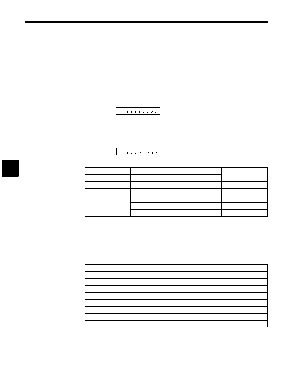
4
Control Signals
4.3 Using a 12-bit Digital Speed Reference
This section provides information on using a 12-bit digital speed reference input (for stand-alone drive systems
M5A only).
D1 through D12 (12-bit Digital References 1 through 12)
J
Connector number: 1CN
Pin numbers: 19 through 30
12-bit Digital Reference Signal Function Selection: 1CN-19 to 1CN-30 will be the 12-bit Digital Reference if bit 07 of the C1-36 selection signals (SEL1) is turned OFF.
C1−36
Bit 7
D
Bit 7 is used for internal speed or digital speed settings.
D
It is possible to select 12-bit binary, 2-digit BCD, 3-digit BCD, or internal speed setting for digital
speed references. Speed references are factory-set to 12-bit binary.
D
The setting method can be selected using bits 6 and 7 of selection signal C1-37 (SEL2).
C1−37
Bit 7 6
D
Selecting the Speed Setting
6CN-5, 19 C1-37 (SEL2)
DAS Bit 7 Bit 6
OFF
ON
--- --- Analog speed
OFF OFF 2-digit BCD
OFF ON Binary
ON OFF 3-digit BCD
ON ON Internal speed
Speed Selection
D
The DAS signal can be switched only when the system is not in operation.
D
If the binary, BCD, or internal speed setting method is selected, the forward or reverse rotation of the
motor is selected with the external FWD or REV relay signal.
Internal Speed Setting
Number of speed settings: 8
Speed set value: Input into C1-41 through C1-48 the percentages based on the rated speed set for C1-26
(S100). Set range: 0.00 to 100.00
Control Constant Signal Name 1CN Input Pin Number
C1-41
C1-42
C1-43
C1-44
C1-45
C1-46
C1-47
C1-48
D
If two or more speed selection signals (D1 through D8) are turned ON at the same time, the smaller
SPD1 Internal speed setting 1 D1 19
SPD2 Internal speed setting 2 D2 20
SPD3 Internal speed setting 3 D3 21
SPD4 Internal speed setting 4 D4 22
SPD5 Internal speed setting 5 D5 23
SPD6 Internal speed setting 6 D6 24
SPD7 Internal speed setting 7 D7 25
SPD8 Internal speed setting 8 D8 26
selection signal number will be enabled. (For example, if D2 and D5 are turned ON simultaneously,
D2 will be enabled.)
D
If all speed selection signals are OFF, the speed references are treated as 0.
D
No speed reference values in C1-41 through C1-48 can be changed while the system is in operation.
4 -10
Page 86

4.3 Using a 12-bit Digital Speed Reference
Digital Speed Settings
Signal 1CN Pin Number 12-bit Binary 3-digit BCD 2-digit BCD
D1
D2
D3
D4
D5
D6
D7
D8
D9
D10
D11
D12
D
All signals will be ON with the rated speed reference set in C1-26 if the 12-bit binary setting is selected.
D
If the 3- or 2-digit BCD setting is selected, a rated speed reference of 999 or 99 will be set in C1-26
19 1 1 ---
20 2 2 ---
21 4 4 ---
22 8 8 ---
23 16 10 1
24 32 20 2
25 64 40 4
26 128 80 8
27 256 100 10
28 512 200 20
29 1024 400 40
30 2048 800 80
respectively.
The input signal circuit for digital speed references is the same as the sequence input signal circuit explained
in 3.4.4 Sequence Input Signal Circuit (for Stand-alone Drive).
4
4-11
Page 87

Control Signals
4.4.1 Connecting Sequence Output Signals
4.4 Sequence Output Signals
This section provides information on the connections, functions, displays, and meanings of the sequence output
signals.
4.4.1 Connecting Sequence Output Signals
The connection of sequence output signals varies between stand-alone drives and NC systems as described
below.
M5A for Independent Drives
J
Connect sequence output signals to the 6CN connector of the I/O card. Refer to 3.4.5 Sequence Output
Signal Circuits for details.
M5N for NC Systems
J
The Inverter performs serial transmission of sequence output signals with NC machines over YENET1200
communications. Refer to the manual of the NC machine for sequence output signals and output addresses.
4.4.2 Setting Sequence Output Signals
Level changes in the following sequence output signals are possible with constant settings. For details,
refer to 4.4.4 Details on Sequence Output Signals.
4
Table 4.2 Constants of Sequence Output Signals
6CN
Pin
No.
No.
1 33
2 34
3 35
4 36
5 37
6 38
7 39
8 40
9 43, 44
10 46
Signal
(M5)
ZSPD
AGR
SDET
TDET
TLE
ORG
ORE
CHWE
FLT
TALM
Function Related Constants
Zero-speed
Speed agree
Speed detection
Torque detection
Torque limit
Load shaft origin
Orientation
completion
Winding selection
completion
Fault signal
Minor fault signal
C1-19 (Zero-speed detection level)
C1-20 (Speed agree detection width)
C1-38 Bit 6 (AGR output condition selection)
C1-21 (Speed detection signal level)
C1-22 (Speed detection signal detection width)
C1-23 (Torque detection signal operation level
C1-40 Bit 2 (TDET output method selection)
C2-09 or C3-09 (Positioning completion detection width)
C2-10 or C3-10 (Positioning completion cancel width)
4.4.3 Status Display of Sequence Output Signals
The ON/OFF status of output signals can be checked with the U1-10 operation status display. The LED
indicators on the Digital Operator will light as shown below to indicate signal status. Refer to Section 5
Operating the Digital Operator for operating procedures.
−
−
−
−
−
UI-10
Output signal
status
Note: The LED indicator lights to indicate that the corresponding input signal is ON.
Fig 4.2 Display of Output Signal Status
FC0
ZSPD
ORG
4-12
FC1
ORE
AGR
SDET
CHWE
FC2
FC3
TDET
FLT
TLE
TALM
FLTL
Page 88

4.4.4 Details on Sequence Output Signals
This section provides information on each of sequence output signal. Pin numbers are given for independent drive operation (M5A). Refer to the manual for the NC machine for sequence output signals and output addresses.
ZSPD (Zero-speed Signal)
J
Connector number: 6CN
Pin numbers:
33
42
D
The ZPSD signal will turn ON when the motor speed drops to the set speed or less. Once the ZPSD
signal turns ON, it will be kept on hold for 50 ms.
ON
[ZSPD]
4.4 Sequence Output Signals
6000 min
D
The C1-19 (ZS
D
The ZSPD signal is output regardless of the status of the FWD or REV output. Therefore, the ZSPD
−1
Reverse
Zero-speed detection level (C1-19)
) can be set to a zero-speed detection level between 3 and 60 min−1.
LVL
signal can be used as an interlock signal for hazard prevention.
AGR (Speed Agree Signal)
J
Connector number: 6CN
Pin numbers:
34
42
D
The AGR signal will turn ON when the motor speed reaches the range set by the SCOM signal. The
AGR signal will not, however, turn ON while the gate is blocked or the motor winding is selected.
D
Once the AGR signal turns ON, it will be kept on hold for 50 ms.
D
The AGR signal can be used in response to the S reference for NC machines in program operation to
go to the next step.
D
The C1-20 (AGRBD) can be set to a speed agree signal detection width between ±10% and ±50%.
Operation Example of Speed Agree Signal
Speed reference vs. motor speed
15%
AGR is OFF
C1−20 = 15%
Forward
6000 min
−1
4
4%
AGR is ON
0
25%
100% speed reference
4 -13
Page 89

Control Signals
4.4.4 Details on Sequence Output Signals
SDET (Speed Detection Signal)
J
Connector number: 6CN
Pin numbers:
D
The SDET signal will turn ON when the motor speed reaches the preset value or less.
D
The speed detection level is set between 0% and 100% in the C1-21 (SD
Speed
35
42
) control constant.
LVL
4
Detection
level
(C1−21)
ON OFF ON
D
Set the hysteresis width of the SDET signal in the C1-22 (SD
D
The SDET operates regardless of the operation signal.
TDET (Torque Detection Signal)
J
Connector number: 6CN
Pin numbers:
36
42
D
The TDET signal will turn ON when the torque reference reaches the preset value or less.
D
Once TDET turns OFF, the status is held for 50 ms.
D
The torque detection level is set between 5% and 120% of the 30-minute rating for the C1-23 (TD
time constant. There is an hysteresis of ±10% of the set value for the operation point.
D
Bit 2 of selection signals C1-40 (SEL5) can be turned ON to prevent TDET from turning OFF even
if the torque references exceeds the set value during acceleration and deceleration.
D
The TDET signal can be used to check the operation of the torque limit or load.
TLE (Torque Control Signal)
J
Connector number: 6CN
Pin numbers:
Time
) control constant.
HYS
LVL
)
D
The TLE signal turns ON when the TLL or TLH torque control signal turns ON.
D
The TLE signal can be used to check the TLL or TLH signal.
37
42
4-14
Page 90

CHWE (Winding Selection Completion Signal)
J
Connector number: 6CN
Pin numbers:
40
42
D
CHWE signals completion of motor winding selection.
D
The CHWE signal is usually ON when the motor is in operation. When the CHW signal is ON, the
CHWE signal will turn OFF until the winding is switched. The CHWE signal will turn ON again on
completion of the winding selection.
D
If the CHWE signal is not output within a preset time after the CHW signal is input, the AL-20 fault
(winding selection fault) will result and the system will stop the motor.
D
While the winding is selected, the AGR signal will turn OFF if the winding selection is implemented
while the motor is rotating at constant speed.
4.4 Sequence Output Signals
[CHW]
Winding
[CHWE]
[AGR]
ORE (Orientation Completion Signal)
J
High speed
ON
ON
Connector number: 6CN
Pin number:
39
42
D
The ORE signal will turn ON when the ORT signal input turns ON and when the load shaft is close
to the specified stop position.
D
While the ORE signal is ON, the deviation of the position will be compensated with countertorque is
generated to offset external force. Make tool or workpiece changes while the ORE signal is ON.
D
The ORE signal will turn OFF if the external force is high and the deviation of the position is excessive.
In that case, arrange a sequence to result an orientation fault.
ORG (Load Shaft Origin) Signal
J
Connector number: 6CN
Pin numbers:
ON
Low speed
ON
ON
4
D
A single pulse is output per load shaft rotation by using the magnetic sensor signal.
D
The ORG signal will turn ON when the load shaft is rotating at the rate of 1000 min−1or less.
38
42
4 -15
Page 91

Control Signals
4.4.4 Details on Sequence Output Signals
FLT (Fault Bit Signal)
J
Connector number: 6CN
Pin numbers:
D
The motor current will be shut off instantly when the protective circuit operates for overcurrent or overload protection and the motor will coast to a stop. The FLT signal will be output when the current is
shut off.
D
The FLT relay is of SPDT contact construction and operates together with the protective circuit.
D
Turn OFF the FWD, REV or ORT signal while the FLT signal is output and then display the fault at
the host system.
D
The fault number is displayed when the FLTL is output. Refer to the fault number.
D
For the relationship between the FLT and RST signals, refer to the RST signal in 4.1.4 Details on Sequence Input Signals.
FC0 to FC3 (Fault Code Signals 0 to 3)
J
Connector number: 6CN
Pin numbers:
43
44
45
4
26
27
28
29
30
D
A fault code signal is output to provide the details of the operation of the protective function.
D
Refer to tables 12.1 and 12.2 for the details of fault codes.
4 -16
Page 92

TALM (Minor Fault Signal)
J
Connector number: 6CN
Pin numbers:
46
30
D
The TALM signal turns ON when a motor overheat alarm 1, heatsink overheat alarm 1, or control card
temperature alarm 1 is detected. The system will continue operating.
D
The FLTL signal will turn ON if any of the following conditions continues while the TALM signal is
ON, the current will be shut off, and the system will stop.
Motor overheat alarm 1 continues one minute (AL-40 will change to AL-41)
Heatsink overheat alarm continues one minute (AL-43 will change to AL-44)
Control card temperature exceeds 85°C (185°F) (AL-46 will change to AL-47)
The TALM signal will be output if there is a minor fault in an optional function, such as an orientation
fault.
FLTL (Fault Signal)
J
Connector number: 6CN
Pin numbers:
4.4 Sequence Output Signals
41
30
D
The FLTL signal will turn OFF if a fault occurs. The FLTL signal is ON while the system is in normal
operation.
D
The output conditions for the FLTL signal are the same as those for the FLT signal.
D
The motor current will be shut off instantly when the protective circuit operates for overcurrent or overload protection and the motor will coast to a stop. The FLTL signal will be output when the current
is shut off.
D
Turn OFF the FWD, REV and ORT signal OFF while the FLT signal is being output, and then display
the fault at the host system.
D
The fault number is displayed when the FLTL is output. Refer to the fault number.
D
For the relationship between the FLT and RST signals, refer to the RST signal in 4.1.4 Details on Sequence Input Signals.
4
4 -17
Page 93

4
Control Signals
4.5 Analog Monitor Signals
The following conditions and specifications apply to analog output signals (for stand-alone drive systems M5A
only).
SM (Speed Meter Signal)
J
Connector number: 6CN
Pin number: 47
The motor speed can be monitored with an external speed meter connected.
D
The SM signal is a DC voltage signal that is output in proportion to the speed regardless of the direction
D
of rotation.
Use a voltmeter as the speed meter with the following specifications.
D
Item
Operation principle
Rating
Internal resistance
Grade
The rated SM signal output (10 V) will turn ON when the motor is rotating at the speed set in C1-26
D
(S
), the rated speed set constant.
100
The SM signal level can be adjusted with C1-16 (SM
D
The C1-16 (SM
D
fected by changing the set value of C1-16.
The SM signal precision is less than 3% of the rated value when the motor is in reverse operation.
D
LM (Load Rate Signal)
J
Connector number: 6CN
Pin number: 50
The load rate signal indicates the load rate based on the rated output.
D
The meter used must have the same specifications as the one for the speed meter.
D
The load rate signal level can be adjusted with C1-17 (LM
D
scale setting.
Item Specification
Voltmeter
Moving coil
10 V full scale
10 kΩ
2.5 or over
), the control constant.
ADJ
) control constant is for speed adjustment. The actual motor speed will not be af-
ADJ
) for control and C1-18 (L
ADJ
MFS
) for full-
INFO
Use 6CN pin 48 and 6CN pin 49 for the 0 V on the meter.
4 -18
Page 94

4.6 Encoder Pulse Input Circuit
Phase A, B, and C (origin) signals [PA,*PA, PB, *PB, PC, *PC] are input into the 2CN connector from the 1024
P/R motor encoder.
An asterisk indicates a reversed signal. The input signals have the following specifications.
Signal Configuration
J
90°phase-difference, two-phase pulse (A and B), and marker pulse (C)
Input Circuit Configuration
J
The input circuit is a line receiver with RS-422-A specifications.
4.6 Encoder Pulse Input Circuit
Inverter
+5 V
(300 mA max)
Phase A
Phase B
Phase C
Line receiver
equivalent to
SN75175
4, 5, 6
1, 2, 3
0V
CR
CR
CR
SS
P
indicates shielded
twisted-pair wires.
2CN
16
17
18
19
14
15
7
PA
*PA
PB
*PB
PC
*PC
Encoder
+5 V
P
Phase A
4
P
P
Output line driver
equivalent to
SN75174
Phase B
Phase C
Fig 4.3 Encoder Pulse Input Circuit
Input Phase
J
Fig 4.4 Input Phase
Phase A
(PA)
Phase B
(PB)
Phase C
(PC)
90°
(a) Forward
4 -19
Phase A
(PA)
90°
Phase B
(PB)
Phase C
(PC)
(b) Reverse
Page 95

Control Signals
4.7 Encoder Pulse Output Circuit
Phase A, B, and C (origin) signals are output from the motor encoder.
An asterisk indicates a reversed signal.
The output signals have the following specifications and can be used for position feedback.
Signal Configuration
J
90°phase-difference, two-phase pulse (A and B), and marker pulse (C)
Output Circuit Configuration
J
The output circuit is a line receiver with RS-422A specifications. Use a line receiver with specifications
matching the RS-422A specifications for signal exchange as shown in the following connection example.
4
Output Phase
J
Inverter
Phase A
Phase B
Phase C
Output line driver
SN75174
1CN
P
13
PAO
*PAO
14
PBO
15
*PBO
16
PCO
11
*PCO
12
17
indicates shielded twisted-pair wires.
Fig 4.5 Encoder Pulse Output Circuit
Receiver circuit (prepared by user)
P
P
P
R
C
T
R
R
T
C
T
T
C
T
T
R
51 to 200Ω
:
T
C
47 to 200PF
T:
Use a line receiver matching
EIA RS-422A standards,
such as the SN75175.
Phase A
Phase B
Phase C
Fig 4.6 Output Phase
Phase A
(PAO)
Phase B
(PBO)
Phase C
(PCO)
90°
(a) Forward
4 -20
Phase A
(PAO)
Phase B
(PBO)
Phase C
(PCO)
90°
(b) Reverse
Page 96

5
Operating the Digital Operator
This chapter explains the functions, operating methods, details on control
constants for the Digital Operator.
5.1 Function of the Digital Operator 5 -2.........
5.2 Display Mode Configuration 5 -5.............
5.3 Key Operations and Display 5 -6.............
5.3.1 Indication at Power-ON 5 -6.......................
5.3.2 Switching Display Functions 5 -6...................
5.3.3 Operation Status Display Mode 5 -7................
5.3.4 Control Constant Display Mode 5 -7................
5.3.5 Digital Operator Operation Mode 5 -8...............
5.3.6 Fault Display Mode 5 -10..........................
5.3.7 Fault Record Display Mode 5 -11...................
5
5-1
Page 97

Operating the Digital Operator
5.1 Function of the Digital Operator
The Digital Operator enables the following:
J
Display of Control Signal Status
Status of control signals of each unit is displayed by monitoring the status of operation. For the display
items, see Chapter 11 Operating Status Displays.
J
Display and Setup of Control Constants
Control constants must be set up for normal operation in compliance with the specifications.
Chapter 10 Control Constants lists the control constants.
J
Display of Protective Functions
If an error occurs during operation, protective functions are displayed. 12.2 Converter Faults and 12.3 In-
verter Faults list the protective functions. These are not displayed when operation is normal.
J
Functions Using the Digital Operator
Stand-alone operation without sequence input signals or speed reference is possible by using the Digital
Operator. This function is effective for test run of inverter/converter connected only to motor. For the details of the operation, see Par. 5.3 (5) “Digital Operator Operation Mode.”
5
5-2
Page 98

Fig. 5.1 shows the display section and operation keys of the Digital Operator, and Fig. 5.2 shows the LED display status of the RUN and STOP keys. Table 5.1 shows the displayed characters and the corresponding alphabets and numbers, and Fig. 5.3 shows the display of bit selection signal.
Run Command Key
These are run command keys when the drive is oper-
ated by the Digital Operator. These keys are effective
only in operation by Digital Operator.
DRIVE/PRGM: Emergency stop
JOG: Jog run:
FWD/REV:Forward and reverse rotation switch
RUN: Run command
STOP:Stop command
When this key is depressed, the operation speedis reduced and stopped.
Then current is interrupted.
When this key is held down, jogging
is possible.
When this key is depressed, direction
of rotation is changed.
When RUN is depressed, the red LED on
the left part of the key lights.
When STOP is depressed, the red LED on
the left part of the key lights.
DRIVE FWD REV REMOTE
DRIVE FWD REV
Digital Operator
JVOP-132
LOCAL
REMOTE
DRIVE
JOG
FWD
REV
RUN STOP
JOG
REMOTE
PRGM
ENTER
REFSEQ
DSPL
DATA
RESET
5.1 Function of the Digital Operator
Mode Display LED
Digital Operator Running Indication
Lights in the Digital Operator operation mode.
Rotation Direction Indication
FWD: Lights when forward run command is
input.
REV: Lights when reverse run command is
input.
Remote Mode Indication
SEQ: Lights when themotorrotatesin the re-
verse direction.
REF: — — —
REFSEQ
Display
Displays monitored values of speed reference
and function set values.
Display Selection Key
Depress this key to select display items.
Read/Write Key
Depress this key to display set values of
constants. Depress this key again to write
set values.
5
Numeral Change Key
Use these keys to change values such as set
values and constant Nos.
∧: Increment key
∨: Decrement key
Digit Selection Key
Use this key to select a position in a set val-
ue to be changed. The selected position
blinks. (Use this key to reset after and error
occurs.)
Fig 5.1 Display Unit and Operation Keys of the Digital Operator
RUN and STOP LEDs light, blink, and go OFF depending on the status of operation.
FWD
REV
RUN STOP
JOG
Fig 5.2 LED Display of RUN and STOP Keys
RESET
Motor Speed
[FWD]or [REV]
Speed Reference
Main Circuit Power Supply
RUN
LED
STOP
LED
5-3
ON Blink OFF
Page 99

Operating the Digital Operator
Table 5.1 Indication of Numbers and Letters by 7-segment LED
Numbers Letters
0 A N −
1 B O −
2 C P
3 D Q −
4 E R
5 F S −
6 G − T −
7 H − U
5
8 I
9 J − W −
.
− L Y −
Note: “—” is not displayed.
76
Bit
G
54 32 10
K
M − Z −
1: ON
0: OFF
Selection signal 0 (OFF) indicates “ ”
and 1 (ON) indicates “ .”
−
−
V −
X −
Fig 5.3 Display of Bit Selection Signal
5-4
Page 100

5.2 Display Mode Configuration
The following figure shows the displays of the Digital Operator. Whenever the DSPL (display selection) key
is pressed, the display mode will change.
Control power ON
5.2 Display Mode Configuration
Uj-jj
Cj-jj
All LEDs light (for 1.5 s).
PROM version No. is displayed (for 0.5 s).
U1-01 (motor speed) data is displayed.
The operating status is displayed.
The control constants are displayed.
C1-37 (bits 1 and 0) turned ON.
d1-jj
*
Alarm is ON.
The Digital Operator operation
reference is displayed.
5
* “88888” will be display if the model is the M5N for NC systems until communications with
the NC machine are established.
Fig 5.4 Display Order of Digital Operator
jALjj
Alarm is ON.
AL-jj
The alarm log is displayed.
5-5
The alarm number is displayed.
 Loading...