

YASKAWA CIMR-LC2A0060, CIMR-LC2A0033, CIMR-LC2A0115, CIMR-LC2A0075, CIMR-LC2A0085 Quick Start Manual
...Page 1
YASKAWA AC Drive L1000A
AC Drive for Elevator Applications
Quick Start Guide
MANUAL NO. TOEP C710616 33A
Type: CIMR-LC¨A
Models:
200 V Class: 4.0 to 45 kW
400 V Class: 4.0 to 75 kW
To properly use the product, read this manual thoroughly and retain
for easy reference, inspection, and maintenance. Ensure the end user
receives this manual.
PDF compression, OCR, web optimization using a watermarked evaluation copy of CVISION PDFCompressor
Page 2

2 YASKAWA ELECTRIC TOEP C710616 33A YASKAWA AC Drive L1000A Quick Start Guide
Copyright © 2009 YASKAWA ELECTRIC CORPORATION. All rights reserved.
All rights reserved. No part of this publication may be reproduced, stored in a retrieval system, or transmitted, in any form, or by any
means, mechanical, electronic, photocopying, recording, or otherwise, without the prior written permission of Yaskawa. No patent
liability is assumed with respect to the use of the information contained herein. Moreover, because Yaskawa is constantly striving to
improve its high-quality products, the information contained in this manual is subject to change without notice. Every precaution has
been taken in the preparation of this manual. Nevertheless, Yaskawa assumes no responsibility for errors or omissions. Neither is
any liability assumed for damages resulting from the use of the information contained in this publication.
PDF compression, OCR, web optimization using a watermarked evaluation copy of CVISION PDFCompressor
Page 3

Table of Contents
1 SAFETY INSTRUCTIONS AND GENERAL WARNINGS . . . . . . . . . . . . . . . . . . . . . . . 4
2 MECHANICAL INSTALLATION . . . . . . . . . . . . . . . . . . . . . . . . . . . . . . . . . . . . . . . . . . . 8
3 ELECTRICAL INSTALLATION. . . . . . . . . . . . . . . . . . . . . . . . . . . . . . . . . . . . . . . . . . . 10
4 KEYPAD OPERATION . . . . . . . . . . . . . . . . . . . . . . . . . . . . . . . . . . . . . . . . . . . . . . . . . 16
5 START UP. . . . . . . . . . . . . . . . . . . . . . . . . . . . . . . . . . . . . . . . . . . . . . . . . . . . . . . . . . . 18
6 FINE ADJUSTMENTS. . . . . . . . . . . . . . . . . . . . . . . . . . . . . . . . . . . . . . . . . . . . . . . . . . 30
7 PARAMETER TABLE . . . . . . . . . . . . . . . . . . . . . . . . . . . . . . . . . . . . . . . . . . . . . . . . . . 32
8 TROUBLESHOOTING . . . . . . . . . . . . . . . . . . . . . . . . . . . . . . . . . . . . . . . . . . . . . . . . . 36
9 SAFE DISABLE INPUT FUNCTION . . . . . . . . . . . . . . . . . . . . . . . . . . . . . . . . . . . . . . . 41
PDF compression, OCR, web optimization using a watermarked evaluation copy of CVISION PDFCompressor
YASKAWA ELECTRIC TOEP C710616 33A YASKAWA AC Drive L1000A Quick Start Guide 3
Page 4
1 Safety Instructions and General Warnings
1 Safety Instructions and General Warnings
Yaskawa Electric supplies component parts for use in a wide variety of industrial applications. The selection and
application of Yaskawa products remain the responsibility of the equipment designer or end user. Yaskawa accepts no
responsibility for the way its products are incorporated into the final system design. Under no circumstances should any
Yaskawa product be incorporated into any product or design as the exclusive or sole safety control. Without exception,
all controls should be designed to detect faults dynamically and fail safely under all circumstances. All products designed
to incorporate a component part manufactured by Yaskawa must be supplied to the end user with appropriate warnings
and instructions as to the safe use and operation of that part. Any warnings provided by Yaskawa must be promptly
provided to the end user. Yaskawa offers an express warranty only as to the quality of its products in conforming to
standards and specifications published in the manual. NO OTHER WARRANTY, EXPRESS OR IMPLIED, IS
OFFERED. Yaskawa assumes no liability for any personal injury, property damage, losses, or claims arising from
misapplication of its products.
Applicable Documentation
The following manuals are available for L1000A series drives:
General Warnings
The following conventions are used to indicate safety messages in this manual:
L1000A Series AC Drive Technical Manual
This manual gives detailed instructions on installation, wiring, operation procedures, functions,
troubleshooting, maintenance, and inspections to perform before operation. Contact your sales
representative for ordering this book or download it from www.yaskawa.eu.com.
L1000A Series AC Drive Quick Start Guide
Read this manual first. This guide is packaged together with the product. It contains basic
information required to install and wire the drive. This guide provides basic programming and
simple setup and adjustment.
W ARNING
• Read and understand the manuals available before installing, operating or servicing this drive.
• All warnings, cautions, and instructions must be followed.
• All work must be performed by qualified personnel.
• The drive must be installed according to this manual and local codes.
Heed the safety messages in this manual.
The operating company is responsible for any injuries or equipment damage resulting from failure to heed the warnings
in this manual.
W ARNING
Indicates a hazardous situation, which, if not avoided, could result in death or serious injury.
CAUTION
Indicates a hazardous situation, which, if not avoided, could result in minor or moderate injury.
NOTICE
Indicates a property damage message.
CIMR-AA2A0021FAA
200V 3Phase 5.5kW/3.7kW
S/N:
危 険
据え付け、運転の前には必ず取扱説明書を読むこと。
通電中および電源遮断後5分以内はフロントカバー
を外さない事。
400V級インバータの場合は、電源の中性点が接地
されていることを確認すること。(対応)
保守・点検、配線を行う場合は、出力側開閉器を
遮断後5分待って実施してください。
けが.感電のおそれがあります。
高温注意
インバータ上部、両側面は高温になります。
触らないでください。
●
●
●
●
●
AVERTISSMENT
NPJT31470-1
Lire le manuel avant l'installation.
Attendre 5 minutes après la coupure
de l'alimentation, pour permettre
la décharge des condensateurs.
Pour répondre aux exigences , s
assurer que le neutre soit relié
à la terre, pour la série 400V.
Après avoir déconnécte la protection
entre le driver et le moteur, veuillez
patienter 5 minutes avain d’effectuer
une opération de montage ou de
câblage du variateur.
Risque de décharge électrique.
Surfaces Chaudes
Dessus et cotés du boitier Peuvent
devenir chaud. Ne Pas toucher.
WARNING
Read manual before installing.
Wait 5 minutes for capacitor
discharge after disconnecting
power supply.
To conform to requirements,
make sure to ground the supply
neutral for 400V class.
After opening the manual switch
between the drive and motor,
please wait 5 minutes before
inspecting, performing
maintenance or wiring the drive.
Risk of electric shock.
Hot surfaces
Top and Side surfaces may
become hot. Do not touch.
●
●
●
●
●
●
●
●
●
●
●
●
●
●
●
LO
RE
F2F1
ESC
RUN STOP
ENTERRESET
ALM
DIGITAL OPERATOR JVOP-180
4 YASKAWA ELECTRIC TOEP C710616 33A YASKAWA AC Drive L1000A Quick Start Guide
PDF compression, OCR, web optimization using a watermarked evaluation copy of CVISION PDFCompressor
Page 5

1 Safety Instructions and General Warnings
W ARNING
Electrical Shock Hazard
Do not attempt to modify or alter the drive in any way not explained in this manual.
Failure to comply could result in death or serious injury.
Yaskawa is not responsible for any modification of the product made by the user. This product must not be modified.
Do not touch any terminals before the capacitors have fully discharged.
Failure to comply could result in death or serious injury.
Before wiring terminals, disconnect all power to the equipment. The internal capacitor remains charged even after the
power supply is turned off. The charge indicator LED will extinguish when the DC bus voltage is below 50 Vdc. To
prevent electric shock, wait at least five minutes after all indicators are off and measure the DC bus voltage level to
confirm safe level.
Do not allow unqualified personnel to use equipment.
Failure to comply could result in death or serious injury.
Maintenance, inspection, and replacement of parts must be performed only by authorized personnel familiar with
installation, adjustment, and maintenance of AC drives.
Do not remove covers or touch circuit boards while the power is on.
Failure to comply could result in death or serious injury.
Always ground the motor-side grounding terminal.
Improper equipment grounding could result in death or serious injury by contacting the motor case.
Do not perform work on the drive while wearing loose clothing, jewelry or without eye protection.
Failure to comply could result in death or serious injury.
Remove all metal objects such as watches and rings, secure loose clothing, and wear eye protection before beginning
work on the drive.
Never short the output circuits of the drive.
Do not short the output circuits of the drive. Failure to comply could result in death or serious injury.
When using a PM motor, make sure to block the rotor before performing work on the motor or drive output
circuit.
A PM motor generates electrical power if rotated. If connected to the drive, the drive main circuit will be charged even
if the power supply is off. Touching live parts in the drive or output circuit may result in death or serious injury.
Sudden Movement Hazard
Stay clear of the motor during rotational Auto-Tuning. The motor may start operating suddenly.
During automatic starting of equipment, the machine may start moving suddenly, which could result in death or serious
injury.
System may start unexpectedly upon application of power, resulting in death or serious injury.
Clear all personnel from the drive, motor, and machine area before applying power. Secure covers, couplings, shaft
keys, and machine loads before applying power to the drive.
Fire Hazard
Do not use an improper voltage source.
Failure to comply could result in death or serious injury by fire.
Verify that the rated voltage of the drive matches the voltage of the incoming power supply before applying power.
Safety Warnings
PDF compression, OCR, web optimization using a watermarked evaluation copy of CVISION PDFCompressor
YASKAWA ELECTRIC TOEP C710616 33A YASKAWA AC Drive L1000A Quick Start Guide 5
Page 6
1 Safety Instructions and General Warnings
CAUTION
Crush Hazard
Do not carry the drive by the front cover.
Failure to comply may result in minor or moderate injury from the main body of the drive falling.
Burn Hazard
Do not touch the heatsink or braking resistor hardware until a powered-down cooling period has elapsed.
NOTICE
Equipment Hazard
Observe proper electrostatic discharge procedures (ESD) when handling the drive and circuit boards.
Failure to comply may result in ESD damage to the drive circuitry.
Never connect or disconnect the motor from the drive while the drive is outputting voltage.
Improper equipment sequencing could result in damage to the drive.
Do not perform a withstand voltage test on any part of the drive.
Failure to comply could result in damage to the sensitive devices within the drive.
Do not operate damaged equipment.
Failure to comply could result in further damage to the equipment.
Do not connect or operate any equipment with visible damage or missing parts.
Install adequate branch circuit short circuit protection per applicable codes.
Failure to comply could result in damage to the drive.
The drive is suitable for circuits capable of delivering not more than 100,000 RMS symmetrical Amperes, 240 Vac
maximum (200 V Class) and 480 Vac maximum (400V Class).
Do not use unshielded cable for control wiring.
Failure to comply may cause electrical interference resulting in poor system performance. Use shielded twisted-pair
wires and ground the shield to the ground terminal of the drive.
Do not allow unqualified personnel to use the product.
Failure to comply could result in damage to the drive or braking circuit.
Carefully review the braking option instruction manual when connecting a braking option to the drive.
W ARNING
Do not use improper combustible materials.
Failure to comply could result in death or serious injury by fire.
Attach the drive to metal or other noncombustible material.
Do not connect AC line power to output terminals U, V, and W.
Make sure that the power supply lines are connected to main circuit input terminals R/L1, S/L2, T/L3.
Do not connect the AC power line to the output motor terminals of the drive. Failure to comply could result in death or
serious injury by fire as a result of drive damage from line voltage application to output terminals.
Tighten all terminal screws to the specified tightening torque.
Loose electrical connections could result in death or serious injury by fire due to overheating of electrical connections.
PDF compression, OCR, web optimization using a watermarked evaluation copy of CVISION PDFCompressor
6 YASKAWA ELECTRIC TOEP C710616 33A YASKAWA AC Drive L1000A Quick Start Guide
Page 7

1 Safety Instructions and General Warnings
NOTICE
Do not modify the drive circuitry.
Failure to comply could result in damage to the drive and will void warranty.
Yaskawa is not responsible for modification of the product made by the user. This product must not be modified.
Check all the wiring to ensure that all connections are correct after installing the drive and connecting other
devices.
Failure to comply could result in damage to the drive.
Do not connect unapproved LC or RC interference suppression filters, capacitors, or overvoltage protection
devices to the output of the drive.
Using unapproved filters could result in damage to the drive or motor equipment.
Check the motor rotation and elevator movement direction prior to starting up the drive.
The drive puts out voltage in phase sequence U-V-W with an Up command. Make sure the elevator moves up if the
motor is supplied with this phase sequence.
Always remove the ropes when performing Rotational Auto-Tuning.
During Rotational Auto-Tuning the drive turns the motor for a certain time. Not removing the ropes might result in
damage to the equipment.
When using a PM motor, make sure the motor can handle the maximum current delivered by the drive.
Operating the motor with too high current may result in demagnetization.
Precautions for CE Low Voltage Directive Compliance
This drive has been tested according to European standard EN61800-5-1, and it fully complies with the Low Voltage
Directive. The following conditions must be met to maintain compliance when combining this drive with other devices:
Do not use drives in areas with pollution higher than severity 2 and overvoltage category 3 in accordance with IEC664.
Ground the neutral point of the main power supply for 400 V Class drives.
In the drives LC2A0145/0185 and LC4A0112/0150 the wire bending space (space between terminals and cable entry
point) provided is smaller than recommended in the IEC61800-5-1.
Precautions for UL/cUL Standards Compliance
This drive is tested in accordance with UL standard UL508C and complies with UL requirements. The following
conditions must be met to maintain compliance when using this drive in combination with other equipment:
Do not install the drive to an area greater than pollution severity 2 (UL standard).
Use UL-listed copper wires (rated at 75°C) and closed-loop connectors or CSA-certified ring connectors. For details
refer to the Technical Manual.
Wire low voltage wires with NEC Class 1 circuit conductors. Refer to national state or local codes for wiring. Use a class
2 (UL regulations) power supply for the control circuit terminal. For details refer to the Technical Manual.
This drive has undergone the UL short-circuit test, which certifies that during a short circuit in the power supply the
current flow will not rise above 100,000 amps maximum at 240 V for 200 V class drives and 480 V for 400 V class
drives.
The drive internal motor overload protection is UL listed and in accordance with the NEC and CEC. The setup can be
done using the parameters L1-01/02. For details refer to the Technical Manual.
Note: The UL listing of the drives LC2A0145/0185 and LC4A0112/0150 is pending.
PDF compression, OCR, web optimization using a watermarked evaluation copy of CVISION PDFCompressor
YASKAWA ELECTRIC TOEP C710616 33A YASKAWA AC Drive L1000A Quick Start Guide 7
Page 8
2 Mechanical Installation
2 Mechanical Installation
Upon Receipt
Perform the following tasks after receiving the drive:
• Inspect the drive for damage. If the drive appears damaged upon receipt, contact your supplier.
• Verify receipt of the correct model by checking the information on the nameplate. If you have received the wrong
model, contact your supplier.
Installation Environment
For optimum performance life of the drive, install the drive in an environment that meets the conditions listed below.
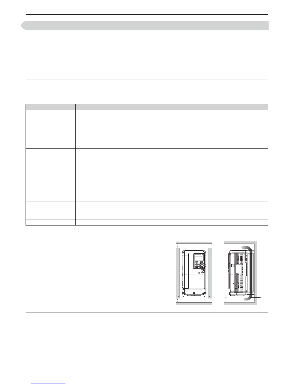
Installation Orientation and Spacing
Always install the drive in an upright position. Leave space around
the unit for proper cooling as shown in the figure on the right.
Degree of Protection
The degree of protection of L1000A drives is IP20. Install the drive in a cabinet if higher degree of protection is required.
Environment Conditions
Installation Area Indoors
Ambient Temperature
–10 to +50°C
Drive reliability improves in environments without wide temperature fluctuations.
When using the drive in an enclosure panel, install a cooling fan or air conditioner in the area to ensure that the air
temperature inside the enclosure does not exceed the specified levels.
Do not allow ice to develop on the drive.
Humidity
95% RH or less and free of condensation
Storage Temperature
–20 to +60°C
Surrounding Area
Install the drive in an area free from:
• oil mist and dust
• metal shavings, oil, water or other foreign materials
• radioactive materials
• combustible materials (e.g., wood)
• harmful gases and liquids
• excessive vibration
• chlorides
• direct sunlight
Altitude
1000 m or lower, up to 3000 m with derating (for details refer to the Technical Manual)
Vibration
10 to 20 Hz at 9.8 m/s
2
20 to 55 Hz at 5.9 m/s
2
Orientation Install the drive vertically to maintain maximum cooling effects.
50 mm
50 mm
30 mm 30 mm
120 mm
120 mm
Air
PDF compression, OCR, web optimization using a watermarked evaluation copy of CVISION PDFCompressor
8 YASKAWA ELECTRIC TOEP C710616 33A YASKAWA AC Drive L1000A Quick Start Guide
Page 9

2 Mechanical Installation
YASKAWA ELECTRIC TOEP C710616 33A YASKAWA AC Drive L1000A Quick Start Guide 9
Dimensions
Model
CIMR-LC
Fig.
Dimensions (mm)
Weight
(kg)
W H D W1 H0 H1 H2 H3 D1 t1 t2 d
2A0018
1
140 260 164 122 – 248 6 – 55 5 – M5 3.5
2A0025 140 260 167 122 – 248 6 – 55 5 – M5 4.0
2A0033 140 260 167 122 – 248 6 – 55 5 – M5 4.0
2A0047 180 300 187 160 – 284 8 – 75 5 – M5 5.6
2A0060 220 350 197 192 – 335 8 – 78 5 – M6 8.7
2A0075 2 220 365 197 192 350 335 8 15 78 5 – M6 9.7
2A0085
3
254 534 258 195 400 385 7.5 134 100 2.3 2.3 M6 23
2A0115 279 614 258 220 450 435 7.5 164 100 2.3 2.3 M6 28
2A0145 329 630 283 260 550 535 7.5 80 110 2.3 2.3 M6 40
2A0180 329 630 283 260 550 535 7.5 80 110 2.3 2.3 M6 40
4A0009
1
140 260 164 122 – 248 6 – 55 5 – M5 3.5
4A0015 140 260 167 122 – 248 6 – 55 5 – M5 3.9
4A0018 140 260 167 122 – 248 6 – 55 5 – M5 3.9
4A0024 180 300 167 160 – 284 8 – 55 5 – M5 5.4
4A0031 180 300 187 160 – 284 8 – 75 5 – M5 5.7
4A0039 220 350 197 192 – 335 8 – 78 5 – M6 8.3
4A0045
3
254 465 258 195 400 385 7.5 65 100 2.3 2.3 M6 23
4A0060 279 515 258 220 450 435 7.5 65 100 2.3 2.3 M6 27
4A0075 329 630 258 260 510 495 7.5 120 105 2.3 3.2 M6 39
4A0091 329 630 258 260 510 495 7.5 120 105 2.3 3.2 M6 39
4A0112 329 630 283 260 550 535 7.5 80 110 2.3 2.3 M6 43
4A0150 329 630 283 260 550 535 7.5 80 110 2.3 2.3 M6 45
W1
H
H1H2
W
D
D1
t1
4-d
Figure 1
H2
W1
H
H0
H1
W
D1
D
t1
H3
4-d
Figure 2
H1H2H0H3
H
W1
W
D
D1
t2
4-d
Max 10Max 10
Figure 3
PDF compression, OCR, web optimization using a watermarked evaluation copy of CVISION PDFCompressor
Page 10

10 YASKAWA ELECTRIC TOEP C710616 33A YASKAWA AC Drive L1000A Quick Start Guide
3 Electrical Installation
3 Electrical Installation
The figure below shows the main and control circuit wiring.
Note: 1. The drive should be implemented in the system in a way so that a drive fault causes the safety chain to open. Always use terminal
MA-MB-MC for this purpose.
2. Even though no fault is present conditions where the drive can not start can occur, e.g. when the Digital Operator is left in the
Programming Mode. Use the “Drive Ready” output (default set to terminals M5-M6) to interlock operation in such situations.
<1> Remove the jumper when installing a DC reactor. Models CIMR-LC2A0085 through 0180 and 4A0045 through 0150 come with a built-in DC
reactor.
<2> The drive provides a stop function in compliance with Stop Category 0 (EN60204-1) and “Safe Torque Off” (IEC61800-5-2). It has been
designed to meet the requirements of the EN954-1/ISO13849-1, Category 3 and IEC61508, SIL2. Using this function the number of motor
contactors can be reduced to one. Refer to
Safe Disable Input Function on page 41 for details.
<3> Never short terminals SP and SN, as doing so will damage the drive.
<4> Disconnect the wire jumper between H1 - HC and H2 - HC when utilizing the Safe Disable inputs.
CN5-C
CN5-B
CN5-A
Option card connectors
Off
On
Three-phase
power supply
200 to 240 Vac or
380 to 480 Vac
50/60 Hz
R/L1
S/L2
T/L3
Main
Switch
Fuse
EMC
Filter
P1
P2
C1
C2
Photo Coupler 1
(During Frequency Output)
Photo Coupler 2
(not used)
Digital output
5 to 48 Vdc
2 to 50 mA
(default setting)
+
−
+
+
++
M
U/T
1
V/T2
W/T
U
V
W
3
Ground
Terminals -, +1, +2, B1, B2 are
for connecting options. Never
connect power supply lines to
these terminals
DC reactor
(option)
U X
Thermal relay
(option)
+
−
+
+
++
+
−
U X
S
1
S2
S3
S4
S5
S6
S7
DM
DM
A
1
A2
0
V
AC
R
R
S
S
IG
H
1
H2
HC
Drive
B
112
B2
2
kΩ
S
8
SC
0 V
FM
AM
AC
E (G)
<1>
−
+24 V
+V
MA
M
1
M2
MB
MC
Jumper
Braking resistor
(option)
Up command / Stop
Nominal Speed
Inspection Operation
Intermediate Speed 1
Not Used
Multi-function
digtial inputs
(default setting)
Sink / Source mode
selection wire link
(default: Sink)
Shield ground terminal
Multi-function
analog inputs
Power supply +10.5 Vdc, max. 20 mA
Analog Input 1 (Speed Bias)
-10 to +10 Vdc (20 kΩ)
Analog Input 2 (Not used)
-10 to +10 Vdc (20 kΩ)
−V
Power supply, -10.5 Vdc, max. 20 mA
MEMOBUS/Modbus
comm. RS485/422
max. 115.2 kBps
Termination resistor
(120 Ω, 1/2 W)
DIP
Switch S2
Fault relay output
250 Vac, max. 1 A
30 Vdc, max 1 A
(min. 5 Vdc, 10 mA)
Multi-function relay output (Brake Control)
250 Vac, max. 1 A
30 Vdc, max 1 A
(min. 5 Vdc, 10 mA)
Multi-function analog output 1
(Output Speed)
-10 to +10 Vdc (2mA)
Multi-function analog output 2
(Output Current)
-10 to +10 Vdc (2mA)
EDM (Safety Electronic Device Monitor)
Main Circuit
Control Circuit
shielded line
twisted-pair shielded line
main circuit terminal
control circuit terminal
R/L1
S/L2
T/L3
Motor
Shielded
Cable
M3
M4
Multi-function relay output (Output Contactor Control)
250 Vac, max. 1 A
30 Vdc, max 1 A
(min. 5 Vdc, 10 mA)
M
5
M6
Multi-function relay output (Drive Ready)
250 Vac, max. 1 A
30 Vdc, max 1 A
(min. 5 Vdc, 10 mA)
SP
SN
DIP Switch S2
Term. Res. On/Off
Jumper S3
H1, H2
Sink/Source Sel.
Terminal board
jumper and switch
FM
+
−
AM
<3>
Down command / Stop
Leveling Speed
Not Used
<2>
<4>
Safe Disable inputs
PDF compression, OCR, web optimization using a watermarked evaluation copy of CVISION PDFCompressor
Page 11

3 Electrical Installation
YASKAWA ELECTRIC TOEP C710616 33A YASKAWA AC Drive L1000A Quick Start Guide 11
Wiring Specification
Main Circuit
Use the fuses and line filters listed in the table below when wiring the main circuit. Do not to exceed the given tightening
torque values.
Tightening Torque Values
Tighten the main circuit terminals using the torque values provided in the table below.
Control Circuit
The control terminal board is equipped with screwless terminals. Always use wires within the specifications listed below.
For safe wiring, Yaskawa recommends solid wires or flexible stranded wires with ferrules. Use ferrules with a length of
8 mm.
Model
CIMR-LC
EMC Filter
[Schaffner]
Main Fuse
[Bussmann]
Recom.
Motor cable
(mm
2
)
Main Circuit Terminal Sizes
R/L1,S/L2,T/L3,
U/T1,V/T2,W/T3, -,
+1, +2
+3 B1, B2
2A0018
FS5972-35-07
FWH-90B 2.5
M4
–
M4
M4
2A0025 FWH-100B 6
M5
2A0033
FS5972-60-07
FWH-200B
10
2A0047
16
M6
M5 M6
2A0060
FS5972-100-35
M8
2A0075
FWH-300A
25
2A0085
FS5972-170-40
35 M8
M8
2A0115 FWH-350A 50
M10
M10
2A0145
FS5972-250-37 FWH-400A
70
M10 – M10
2A0180 95
4A0009 FS5972-18-07 FWH-90B
2.5
M4
–
M4
M4
4A0015
FS5972-35-07
FWH-80B
M5
4A0018 FWH-100B 4
4A0024 FWH-125B
6 M5
M5 M6
4A0031
FS5972-60-07
FWH-200B
4A0039
FWH-250A
16
M6
4A0045
M8
M8
M8
4A0060
FS5972-100-35 25
4A0075
M8 –
4A0091
FS5972-170-40
35
4A0112 FWH-350A 50
M10 M10 – M10
4A0150 FWH-400A 70
Terminal Size M4 M5 M6 M8 M10
Tightening Torque (Nxm) 1.2 to 1.5 2.0 to 2.5 4.0 to 6.0 9.0 to 11.0 18.0 to 23.0
Wire Type Wire size (mm2)
Solid 0.2 to 1.5
Stranded 0.2 to 1.0
Stranded wire with ferrule 0.25 to 0.5
PDF compression, OCR, web optimization using a watermarked evaluation copy of CVISION PDFCompressor
Page 12

3 Electrical Installation
12 YASKAWA ELECTRIC TOEP C710616 33A YASKAWA AC Drive L1000A Quick Start Guide
EMC Filter Installation
This drive has been tested in accordance with European standards EN61800-3. Install the drive and wire the main circuit
as described below.
1. Install an appropriate EMC noise filter to the input side. See the table in
Main Circuit on page 11 or refer to the
Technical Manual for details.
2. Place the drive and EMC noise filter in the same enclosure.
3. Use braided shield cable for motor and control circuit wiring.
4. Remove any paint or dirt from ground connections for minimal ground impedance.
5. Install an AC or DC reactor for EN12015 compliance. Refer to the Technical Manual or contact your supplier for
details.
Main and Control Circuit Wiring
Wiring the Main Circuit Input
Note the following precautions when wiring the main circuit input.
• Use only fuses recommended in
Main Circuit on page 11.
• If using a ground fault circuit breaker, make sure the breaker is designed for use with AC drives (e.g., type B according
to ICE60755).
• If using an input switch, make sure that the switch does not operate more frequently than once every 30 minutes.
• Use a DC reactor or AC reactor on the input side of the drive:
• To suppress harmonic current.
• to improve the power factor on the power supply side.
• when using an advancing capacitor switch.
• with a large capacity power supply transformer (over 600 kVA).
L3 L2 L1L3 L2 L1
E
L3
L2
L1
PE
Make sure the ground wire is grounded
Enclosure panel
Metal plate
Grounding surface
(remove any paint or sealant)
Drive
Grounding surface
(remove any paint or sealant)
Motor cable (braided shield cable, max. 10 m)
Cable clamp
Ground plate
(scrape off any visible paint)
EMC noise filter
Motor
Ground the cable shield
PDF compression, OCR, web optimization using a watermarked evaluation copy of CVISION PDFCompressor
Page 13

3 Electrical Installation
YASKAWA ELECTRIC TOEP C710616 33A YASKAWA AC Drive L1000A Quick Start Guide 13
Wiring the Main Circuit Output
Note the following precautions for the output circuit wiring:
• Do not connect any load other than a three-phase motor to the output side of the drive.
• Never connect a power source to the drive output.
• Never short or ground the output terminals.
• Do not use phase correction capacitors.
• Check the control sequence to make sure that the motor contactor is not turned ON or OFF during drive operation.
Turning on the motor contactor while voltage is output causes an inrush current that is likely to trigger the drive’s
overcurrent protection.
Note: The drive provides a Safe Disable function that can be utilized to reduce the number of motor contactors to one. Refer to Safe
Disable Input Function on page 41 for details.
Ground Connection
Take the following precautions when grounding the drive:
• Never share the ground wire with other devices such as welding machines, etc.
• Always use a ground wire that complies with electrical equipment technical standards. Keep ground wires as short as
possible. Because leakage current is caused by the drive, potential on the ground terminal of the drive will become
unstable if the distance between the ground electrode and the ground terminal is too long.
• Always make sure the ground impedance is conform to the requirements of local safety and installation regulations.
• Do not loop the ground wire when using more than one drive.
Control Circuit Wiring Precautions
Note the following precautions for wiring the control circuits:
• Separate control circuit wiring from main circuit wiring and other high-power lines.
• Separate wiring for control circuit terminals M1 to M6, MA, MB, and MC (contact output) from wiring to other control
circuit terminals.
• Use twisted-pair or shielded twisted-pair cables for control circuits to prevent operating faults.
• Ground the cable shields with the maximum contact area of the shield and ground.
• Cable shields should be grounded on both cable ends.
• Note that flexible wires with ferrules may fit tightly into the terminals. To disconnect them, grasp the wire end with a
pair of pliers, release the terminal using a straight-edge screwdriver, turn the wire for about 45°, and pull it gently out
of the terminal. For details, refer to the Technical Manual. Use this procedure for removing the wire link between HC,
H1, and H2 when the Safe Disable function is utilized.
Main Circuit Terminals
Terminal Type
Function200 V Class
Model
CIMR-LC
2A0018 to 2A0075 2A0085, 2A0115 2A0145, 2A0180
400 V Class 4A0009 to 4A0039 4A0045, 4A0060 4A0075 to 4A0150
R/L1, S/L2, T/L3
Main circuit power supply input Connects line power to the drive
U/T1, V/T2, W/T3
Drive output Connects to the motor
B1, B2
Braking resistor Not available
Available for connecting a braking
resistor or a braking resistor unit option
+2
• DC reactor connection
(+1, +2). Remove the
jumper between +1
and +2
• DC power supply
input (+1, −)
Not available
For connecting
• the drive to a DC power supply
(terminals +1 and – are not EU or UL
approved)
• braking options
• a DC reactor
+1, –
• DC power supply
input (+1, −)
• DC power supply
input (+1, −)
• Braking transistor
connection (+3, −)
+3
Not available
– Grounding terminal
PDF compression, OCR, web optimization using a watermarked evaluation copy of CVISION PDFCompressor
Page 14

3 Electrical Installation
14 YASKAWA ELECTRIC TOEP C710616 33A YASKAWA AC Drive L1000A Quick Start Guide
Control Circuit Terminals
The figure below shows the control circuit terminal arrangement. The drive is equipped with screwless terminals.
DIP switch S2 and jumper S3 are located on the terminal board. Set them as described below.
Sinking/Sourcing Mode (NPN/PNP Selection)
Use a wire link between terminals SC and SP or SC and SN to select between Sink mode, Source mode or external power
supply for the digital inputs S1 to S8 as shown below (Default: Sink mode, internal power supply).
Note: Never short terminals SP and SN as doing so will damage the drive.
S2 RS422/485 Termination Resistor
S3
Safe Disable Input
Sink/Source/External Supply Selection
Internal Power Supply – Sinking Mode (NPN) (default)
External Power Supply – Sinking Mode (NPN)
Internal Power Supply – Sourcing Mode (PNP)
External Power Supply – Sourcing Mode (PNP)
S1 S2 S3 S4 S5 S6 S7 S8 SN SC SP
M1 M2 M5
M3 M4 M6
MA MB MC
V+ AC V- A1 A2 FM AM AC P1 C1 P2 C2
E(G) HC H1 H2
DM+ DM-
IG R+ R- S+ S-
Use a straight-edge screwdriver
with a blade width of max 2.5 mm
and a thickness of max 0.6 mm to
release the terminals
S2
S3
Off
On
Source Sink
External 24 Vdc
Power Supply
SC
S8
S7
24 Vdc
SP
SN
SC
S8
S7
24 Vdc
SP
SN
External
24 Vdc
SC
S8
S7
24 Vdc
SP
SN
SC
S8
S7
24 Vdc
SP
SN
External
24 Vdc
PDF compression, OCR, web optimization using a watermarked evaluation copy of CVISION PDFCompressor
Page 15

3 Electrical Installation
YASKAWA ELECTRIC TOEP C710616 33A YASKAWA AC Drive L1000A Quick Start Guide 15
Control Circuit Terminal Functions
NOTICE: The terminals HC, H1, H2 are used for the Safe Disable function. Safe Disable can be used to enable/disable the drive. If
special requirement are fulfilled, it can also be utilized for reducing the number of motor contactors to one. Refer to
Safe Disable Input
Function on page 41
for details. Always remove the wire link between HC, H1, or H2 when using Safe Disable.
NOTICE: The wiring length to terminals HC, H1 and H2 should not exceed 30 m.
NOTICE: When connecting a reactive load such as a relay coil to a photo coupler output, attach a flywheel diode to the load (relay coil)
like shown below. Ensure the diode rating is greater than the circuit voltage.
Type No. Terminal Name (Function) Function (Signal Level) Default Setting
Digital Inputs
S1
Up Command (Closed: Up, Open: Stop)
Photocoupler
24 Vdc, 8 mA
Use the wire link between terminals SC and SN or between SC and
SP to select sinking or sourcing, and to select the power supply.
S2
Down Command (Closed: Down, Open: Stop)
S3
Multi-function input 3 (Nominal Speed)
S4
Multi-function input 4 (Inspection Operation)
S5
Multi-function input 5 (Intermediate Speed 1)
S6
Multi-function input 6 (Leveling Speed)
S7
Multi-function input 7 (Not used)
S8
Multi-function input 8 (Not used)
Digital Input
Power Supply
SC
Multi-function input common
Photocoupler, 24 Vdc, 8 mA
Use the wire link between terminals SC and SN or between SC and
SP to select sinking or sourcing, and to select the power supply.
SN 0 V
SP +24 Vdc
Safe Disable
Inputs
H1
Safe Disable input 1
24 Vdc, 8 mA
One or both open: Drive output disabled
Both closed: Normal operation
Internal impedance: 3.3 kΩ
Off time of at least 1 ms
Set the S3 jumper to select sinking or sourcing, and to select the
power supply.
H2
Safe Disable input 2
HC
Safe Disable function common Common for the Safe Disable function
Analog Inputs
+V
Power supply for analog inputs 10.5 Vdc (max. allowable current 20 mA)
–V
Power supply for analog inputs –10.5 Vdc (max. allowable current 20 mA)
A1
Multi-function analog input 1 (Speed Reference Bias) –10 to 10 Vdc, 0 to 10 Vdc (input impedance: 20 kΩ)
A2
Multi-function analog input 2 (Not used) –10 to 10 Vdc, 0 to 10 Vdc (input impedance: 20 kΩ)
AC
Analog Input common 0 V
E (G)
Ground for shielded lines and option cards –
Fault Relay
MA
N.O. output
30 Vdc, 10 mA to 1 A; 250 Vac, 10 mA to 1 A
Minimum load: 5 Vdc, 10 mA
MB
N.C. output
MC
Fault output common
Multi-Function
Relay Output
M1
Relay output 1 (Brake Control)
M2
M3
Relay output 2 (Output Contactor Control)
M4
M5
Relay output 3 (Drive Ready)
M6
Multi-Function
Photocoupler
Output
P1
Photocoupler output 1 (During frequency output 2)
Photocoupler output 48 Vdc, 2 to 50 mA
C1
P2
Ph
otocoupler output 2 (Not used)
C2
Monitor Output
FM
Analog monitor output 1 (Output speed)
–10 to +10 Vdc, 0 to +10 Vdc
AM
Analog monitor output 2 (Output current)
AC
Monitor common 0 V
Safety Monitor
Output
DM+
Safety monitor output
Outputs status of Safe Disable function. Closed when both Safe
Disable channels are closed. Up to +48 Vdc 50 mA.
DM–
Safety monitor output common
DC Power
Supply (max 48 V)
Flywheel diode
Reactive
load
I (max 50 mA)
PDF compression, OCR, web optimization using a watermarked evaluation copy of CVISION PDFCompressor
Page 16

16 YASKAWA ELECTRIC TOEP C710616 33A YASKAWA AC Drive L1000A Quick Start Guide
4 Keypad Operation
4 Keypad Operation
Digital Operator and Keys
The digital operator is used to program the drive, to start and stop it, and to display
fault information. The LEDs indicate the operating status of the drive.
Keys and Functions
Key Name Function
Function Key
(F1, F2)
The functions assigned to F1 and F2 vary depending on the menu that is currently displayed. The
name of each function appears in the lower half of the display window.
ESC Key
• Returns to the previous display.
• Moves the cursor one space to the left.
• Pressing and holding this button will return to the Speed Reference display.
RESET Key
• Moves the cursor to the right.
• Resets the drive to clear a fault situation.
RUN Key
Starts the drive in the LOCAL mode.
The Run LED
• is on, when the drive is operating the motor.
• flashes when decelerating to stop (“ramp to stop”), or when the speed reference is 0.
• flashes quickly when the drive is disabled by a DI, when the drive was stopped using a Fast Stop
command via the digital inputs, or when a Run command is active during power up.
Up Arrow Key Scrolls up to display the next item, selects parameter numbers and increments setting values.
Down Arrow Key Scrolls down to display the next item, selects parameter numbers and increments setting values.
STOP Key Stops drive operation.
ENTER Key
• Enters parameter values and settings.
• Selects a menu item to move between displays.
LO/RE Selection
Key
Switches drive control between the operator (LOCAL) and the control circuit terminals
(REMOTE). The LED is on when the drive is in the LOCAL mode (operation from keypad).
ALM LED Light
On: When the drive detects a fault.
Flashing:
• When an alarm occurs.
• When oPE is detected.
• When a fault or error occurs during Auto-Tuning.
LO
RE
F2F1
ESC
RUN STOP
ENTERRESET
ALM
DIGITAL OPERATOR JVOP-180
F1
F2
ESC
RESET
RUN
STOP
ENTER
LO
RE
ALM
PDF compression, OCR, web optimization using a watermarked evaluation copy of CVISION PDFCompressor
Page 17

4 Keypad Operation
YASKAWA ELECTRIC TOEP C710616 33A YASKAWA AC Drive L1000A Quick Start Guide 17
Menu Structure and Modes
The following illustration explains the operator keypad menu structure.
Figure1.1
<1> Drive cannot operate the motor.
<2> Flashing characters are shown as .
<3> X characters are shown in this manual. The LCD Operator will display the actual setting values.
<4> The speed reference appears after the initial display which shows the product name.
<5> The information that appears on the display will vary depending on the drive.
- MODE -
U1-01= 0.00%
U1-02= 0.00%
U1-03= 0.00A
DRV
Speed Ref (OPR)
Rdy
-MONITR-
Speed Ref 1
U1-01= 000.00%
<2>
<3>
㧔0.00㨪50.00㧕
0.00%
DRV
φψ
FWD
Rdy
- MODE -
U1-01= 0.00%
U1-02= 0.00%
U1-03= 0.00A
DRV
Monitor Menu
Rdy
- MODE - PRG
Modified Consts
HELP
HELP
DATA
- MODE - PRG
Quick Setting
DATA
HELP
- MODE - PRG Rdy
Auto-Tuning
DATA
HELP
- MODE - PRG
DATA
Programming
AUTO
-MONITRU
1 -01= 0.00%
U1-02= 0.00%
U1-03= 0.00A
DRV
Monitor
FWD
Rdy -MONITR-
U1-
01 = 0.00%
U1-02= 0.00%
U1-03= 0.00A
DRV
Speed Reference
FWD
Rdy
-MONITR-
U1-
02 = 0.00%
U1-03= 0.00A
U1-04= 0
DRV
Output Speed
FWD
Rdy
-MONITRU
2 -01= oC
U2-02= oPr
U2-03= 0.00Hz
DRV
Fault Trace
FWD
Rdy
FWD
FWD
FWD
FWD
FWD
Modified
X Parameters
RSEQ
LREF
RSEQ
LREF
RSEQ
LREF
RSEQ
LREF
RSEQ
LREF
RSEQ
LREF
YASKAWA
L1000A
L1000A
XXXVX.X/X.XkW
XX.XX/XX.XXA
<XXXXXXXXX>
Initial Display <4>
<5>
Programming Mode <1> Drive Mode
FWD
0
PDF compression, OCR, web optimization using a watermarked evaluation copy of CVISION PDFCompressor
Page 18

18 YASKAWA ELECTRIC TOEP C710616 33A YASKAWA AC Drive L1000A Quick Start Guide
5 Start Up
5 Start Up
Drive Setup Procedure
The illustration below shows the basic setup procedure. The steps from switching on power are explained more detailed
on the following pages.
For control modes below, refer to
• V/f Control
• Open Loop Vector Control
• Closed Loop Vector Control
For Closed Loop Vector for PM, refer to
START
Check the encoder power supply selection
(Closed Loop Control only)
Apply main power on to the drive.
Adhere to safety messages concerning application of power.
Perform Auto-Tuning for motor parameters and the encoder offset.
Determine the
source of the speed
reference.
Analog Input
Digital operator (b1-01 = 0)
(Speed selection by digital inputs)
Assign functions to the analog/digital I/O terminals using
parameters H1-¨¨, H2-¨¨, H3-¨¨, and H4-¨¨
Set up the
• Acceleration/deceleration ramp (C1-¨¨)
• Jerk settings (C2-¨¨)
Perform a test run.
Fine-tuning
• Adjust settings for the brake sequence.
• Adjust speed control loop (C5-¨¨) etc.
FINISH
Set up the
• Preset speed references (d1-¨¨)
• Acceleration/deceleration ramp (C1-¨¨)
• Jerk settings (C2-¨¨)
Assign functions to the digital I/O terminals using
parameters H1-¨¨ and H2-¨¨
Set the Speed Reference Selection mode
parameter d1-18
Set up o1-20 to o1-22 and then select the display units for speed,
accerleration and deceleration ramp and jerk settings in o1-03.
Set up the Inspection Operation sequence.
Set up the encoder feedback in F1-!! parameters when using a
Closed Loop Control and check the encoder rotation direction.
Select the control mode in parameter A1-02.
Check the motor rotation direction.
Mechanical installation
Main and control circuit wiring
Auto-Tuning Induction Motors on page 22
Auto-Tuning PM Motors on page 23
PDF compression, OCR, web optimization using a watermarked evaluation copy of CVISION PDFCompressor
Page 19

5 Start Up
Power On
Before turning on the power supply
• Make sure all wires are connected properly. Also make sure motor phases are connected in the right sequence.
• Make sure that no screws, loose wire ends, or tools are left in the drive.
• If an encoder option card is used make sure the encoder is wired correctly and the power supply on the option card is
set according to the encoder specification.
After turning the power on, the drive mode display should appear and no fault or alarm should be displayed. In case of
any error refer to
Troubleshooting on page 36.
Control Mode Selection
When the drive is first powered up, one of the four control modes must be selected to match the application. Note that
Closed Loop Vector modes require encoder feedback cards. The table below indicates possible control modes depending
on the motor type and shows the required encoder feedback card.
Machine Type Control Mode A1-02 setting Encoder Option Card
Induction motor without encoder
Induction motor with incremental encoder Closed Loop Vector Control 3 PG-B3 / PG-X3
Permanent magnet motor with EnDat 2.1/01 or
EnDat 2.2/01 encoder
Yaskawa IPM motor with incremental encoder Closed Loop Vector Control for PM motors 7 PG-X3
V/f Control 0 No card required
Open Loop Vector Control 2 No card required
Closed Loop Vector Control for PM motors 7 PG-F3
Motor Rotation Direction Setup
Depending on the elevator configuration it might be necessary to change the motor direction in order to have the elevator
traveling up when the Up command is given to the drive. Do the following to check the motor rotation direction.
• The drive puts out voltage in U-V-W phase sequence when an Up command is input. Check the motor rotation with
this phase sequence (for most motors clockwise seen from the shaft side).
• If the motor drives the elevator in up direction with a U-V-W sequence, make sure parameter b1-14 is set to 0 (default).
• If the motor drives the elevator in down direction with a U-V-W sequence, set parameter b1-14 is set to 1.
Note: Always perform motor rotation direction setup prior to setting the encoder rotation direction.
Encoder Setup
Encoder Resolution Setup
Set the encoder resolution (incremental signal in case of absolute encoders with Sin/Cos tracks) in parameter F1-01.
Encoder Rotation Direction Setup
Perform the following steps to make sure the encoder rotation direction is set up correctly in the drive.
If information about the signal sequence of the encoder are available
• Check the sequence of encoder phases A and B when the motor drives the elevator in up direction.
• If the encoder A phase leads phase B, make sure F1-05 is set to 0 (default).
• If the encoder B phase leads phase A, make sure F1-05 is set to 1.
If no information about the signal sequence of the encoder are available
• Turn the motor manually in elevator up direction while checking the value of monitor U1-05.
• If the value in U1-05 is positive, the set encoder direction is correct.
• If the value in U1-05 is negative, alter the setting of parameter F1-05.
Note: Always set the motor rotation direction prior to the encoder rotation direction. Refer to Motor Rotation Direction Setup on
page 19.
PDF compression, OCR, web optimization using a watermarked evaluation copy of CVISION PDFCompressor
YASKAWA ELECTRIC TOEP C710616 33A YASKAWA AC Drive L1000A Quick Start Guide 19
Page 20

5 Start Up
Digital Operator Display Unit Selection
The drive allows to choose between different display units for speed related parameters and monitors, acceleration and
deceleration rates and jerk settings. The units can be selected using parameter o1-03 like shown below.
Display Unit
o1-03 Setting
0 0.01 Hz
1 (default) 0.01%
2 1 rpm
3 User defined
4 0.01 m/s
5 0.01 m/s
When using setting 4 or 5 certain mechanical data have to be programmed to the drive prior to changing o1-03. Perform
the following steps.
1. Make sure motor data are set up correctly. Verify the setting of the maximum output frequency in parameter E1-04 and
the setting for the number of motor poles in parameter E2-04 or E5-04.
2. Set the traction sheave diameter in units of mm to parameter o1-20.
3. Set the correct roping to parameter o1-21.
4. If a mechanical gear is used, set the gear ratio (n
sure o1-22 is set to 1.0.
5. Change parameter o1-03 to setting 4 or 5. The unit and setting values of related parameters will be changed
automatically.
Speed Setting/Monitors
(d1-, U1-02, U1-02,...)
Accel/Decel Rates
Motor/nTraction Sheave
(C1-)
0.01 s 0.01 s
2
0.01 m/s
Jerk Settings
(C2-)
3
0.01 m/s
) to parameter o1-22. If a gearbox is not used, make
Motor Data and Encoder Auto-Tuning
Auto-Tuning Types
Auto-Tuning automatically programs the drive’s motor and motor control related parameters. Select between AutoTuning methods listed below.
Motor Data Tuning Modes for Induction Motors (A1-02 = 0, 2, or 3)
Type Setting Requirements and Benefits
• Rotational Auto-Tuning gives the most accurate results, and is therefore
Rotational Auto-Tuning
Stationary Auto-Tuning 1
Stationary Auto-Tuning for
Line-to-Line Resistance
Stationary Auto-Tuning 2
T1-01 = 0
T1-01 = 1
T1-01 = 2
T1-01 = 4
highly recommended if possible.
• Motor must run freely or with light load (<30%), i.e. ropes have to be
removed.
• Automatically calculates motor parameters needed for vector control.
• Use if ropes can not be removed. Note that the accuracy is less then with
Rotational Auto-tuning.
• Used for V/f Control or in vector control modes when the drive was set up
properly before and the motor cable has changed.
• A motor test report is available. The no-load current and the rated slip have
must be entered from the test report, all other motor-related parameters are
calculated automatically.
• Use if ropes can not be removed and if slip and no-load current data are
available.
Motor Data Tuning Modes for Permanent Magnet Motors (A1-02 = 7)
Control Mode (A1-02)
V/f (0) OLV (2) CLV (3)
No Yes Yes
No Yes Yes
Yes Yes Yes
No Yes Yes
Type Setting Requirements and Benefits
Motor Data Input T2-01 = 0
Stationary Auto-Tuning T2-01 = 1
PDF compression, OCR, web optimization using a watermarked evaluation copy of CVISION PDFCompressor
20 YASKAWA ELECTRIC TOEP C710616 33A YASKAWA AC Drive L1000A Quick Start Guide
• Use if a motor test report is available
• Input motor data like on test report. Make sure to convert data into the correct unit before if necessary.
• Use if a motor test report is not available
• Input motor data like on name plate. Make sure to convert data into the correct unit before. The drive
automatically calculates the motor data.
Page 21

5 Start Up
- MODE -
End
Tune Successful
DRV
FWD
RESET
Enter the Auto-Tuning Mode
Select the tuning method
Enter the correct data as listed
on the nameplate
Drive asks if it should start
tuning drive parameters
Display flashes while the
drive measures and sets
motor parameter values
"End" appears when the
process is complete
Drive mode display
- A.TUNE -
T1-
01= 0
∗0∗
Standard Tuning
PRG
Entry Accepted
Tuning Mode Sel
FWD
- A.TUNE -
T1-
01= 0
∗0∗
Standard Tuning
PRG
Tuning Mode Sel
ESC FWD DATA
- MODE U1-01= 0.00%
U1-02= 0.00%
U1-03= 0.00A
DRV
Speed Ref (OPR)
Rdy
JOG FWD/REV
RSEQ
LREF
HELP
- MODE - PRG
Auto-Tuning
DATA
AUTO
FWD
“0”
- A.TUNE -
T1-
07= 1450RPM
(0 ~ 24000)
PRG
Rated Speed
ESC FWD DATA
“1450RPM”
- A.TUNE -
T1-
02= X.XXkW
(0.00 ~ 650.00)
PRG
Mtr Rated Power
ESC FWD DATA
“X.XXkW”
- A.TUNE -
0.00 %/ 0.00A
Tuning Ready ?
DRV
Auto-Tuning
ESC FWD
Press RUN key
- A.TUNE -
X.XX %/ X.XXA
DRV
Tune Proceeding
FWD
FWD
RUN
Type Setting Requirements and Benefits
Stationary Auto-Tuning for
Stator Resistance
Rotational Back EMF
Constant Auto-Tuning
T2-01 = 2
T2-01 = 11
• Tunes stator resistance only.
• Should be performed if the motor cable has changed.
• Used the Motor Induction Voltage (E5-24) if no data are available.
• Should be performed after Motor data have been set and the encoder offset has been adjusted.
• The motor must be uncoupled from the mechanical system (remove ropes).
Encoder Offset Tuning Modes for Permanent Magnet Motors (A1-02 = 7)
Encoder Offset Tuning measures the angle between the encoder zero pulse and the rotor orientation. It needs to be
performed when a drive is setup the first time or after initialization, when the motor rotation direction or encoder rotation
direction has been changed or when the encoder was replaced.
Type Setting Requirements and Benefits
• Attempts to detect the motor rotor position, judges if the encoder offset can be tuned using Stationary
Initial Magnet Pole Search
Parametes Auto-Tuning
T2-01 = 3
Encoder Offset Tuning and sets parameters needed for Initial Magnet Pole Search (n8-36, n8-37).
• Should be performed after motor Auto-tuning in order to decide the encoder tuning method.
Important: When using a PG-X3 card with an incremental encoder and this tuning fails, the motor can
not be driven using and incremental encoder. Change the encoder to an absolute encoder.
Stationary Encoder Offset
Auto-Tuning
Rotational Encoder Offset
Auto-Tuning
T2-01 = 4
T2-01 = 10
• Tunes the encoder offset without rotating the motor.
• If the encoder offset can not be tuned properly by this method run Rotating Encoder Offset Tuning.
• Tunes the encoder offset while rotating the motor.
• Motor and mechanical system must be uncoupled (ropes must be removed from traction sheave).
Tuning Mode Selection and Data Input
For Auto-Tuning, enter the Auto-Tuning menu (via the T parameters) and perform the steps shown in the figure below.
Data required from the motor nameplate will vary depending on the type of Auto-Tuning selected. This example shows
the procedure for performing Rotational Auto-Tuning of an induction motor in Open Loop Vector control.
If Auto-Tuning can not be performed for some reason (no-load operation impossible, etc.), then set the maximum
frequency and voltage in the E1- parameters and enter the motor data manually into the E2- parameters for
induction motors or E5- parameters for PM motors. Refer to
Auto-Tuning Errors on page 39.
Precautions
• Always try to perform Rotational Auto-Tuning as it gives more accurate results than Non-Rotating Auto-Tuning.
Perform Non-Rotating Auto-Tuning if the load can not be disconnected (e.g. ropes can not be removed).
• Make sure that the mechanical brake is closed for all Auto-Tuning methods except for Rotational Auto-Tuning.
• Motor contactors must be closed during the Auto-Tuning process.
• H1 and H2 signals must be ON when performing Auto-Tuning.
• Confirm that the motor is mechanically fixed.
• Do not touch the motor until the Auto-Tuning process is complete. Voltage is applied to the motor during the tuning
process, even though the motor may not be rotating.
• To cancel Auto-Tuning, press the STOP key on the digital operator.
• During Auto-Tuning the motor is started and stopped repeatedly and may also rotate. When the tuning is finished,
“END” will appear on the operator panel. Do not touch the motor until this display is shown and the motor has
completely stopped.
PDF compression, OCR, web optimization using a watermarked evaluation copy of CVISION PDFCompressor
YASKAWA ELECTRIC TOEP C710616 33A YASKAWA AC Drive L1000A Quick Start Guide 21
Page 22

5 Start Up
START
Set terminals H1 and H2 if Safe Disable function is used
Enter the data in to T1-!! parameters as indicated on the
display.
Is the Control Mode
V/f Control ?
Apply the brake if it was released during Auto-tuning.
FINISH
Can the motor
rotate freely?
Stationary Auto-Tuning for
Terminal Resistance
T1-01 = 2.
Select Stationary
Auto-Tuning 1 or 2
T1-01 = 1 or 4.
No
A1-02=2 or 3
Yes
A1-02=0
No
Yes
(ropes removed)
Select Rotational
Auto-Tuning
T1-01 = 0
Press the Up key until “Tuning Ready” is displayed.
Enter the data in to T1-!! parameters as
indicated on the display.
Press the Up key until “Tuning Ready” is
displayed.
Release the Brake.
Close the motor contactor(s).
Press the Run key on the digital operator
and wait until Auto-Tuning is finished.
Set the Baseblock input (H1-!!=8/9) if used.
Tuning
Successful?
Refer to
Remove the Fault/Alarm source and
repeat Auto Tuning.
Open terminals H1-HC and H2-HC if used during the normal sequence.
Open the motor contactor(s).
Open the Baseblock input (H1-!!=8/9) if used.
No
(Alarm or Fault code
displayed
Yes
(”Entry Accepted”
displayed)
Auto-Tuning Errors on page 39
Auto-Tuning Procedure
Auto-Tuning Induction Motors
PDF compression, OCR, web optimization using a watermarked evaluation copy of CVISION PDFCompressor
22 YASKAWA ELECTRIC TOEP C710616 33A YASKAWA AC Drive L1000A Quick Start Guide
Page 23

Auto-Tuning PM Motors
START
Set terminals H1-HC and H2-HC if Safe Disable function is used.
Complete motor
data sheet
available?
FINISH
No
Yes
Select Stationary Auto-Tuning
T2-01 = 1
Continue with encoder offset tuning.
Refer to
Press the Run key on the digital operator
and wait until Auto-Tuning is finished.
Set the Baseblock input (H1-!!=8/9) if used.
Tuning
Successful?
Can the motor
rotate freely?
Refer to
Remove the Fault/Alarm source and
repeat Auto Tuning.
Open terminals H1-HC and H2-HC if used during the normal sequence.
Open the motor contactor(s).
Open the Baseblock input (H1-!!=8/9) if used.
No
(Alarm or Fault code
displayed
Yes
(”Entry Accepted”
displayed)
Enter the data in to T2-!! parameters as
indicated on the display.
Select Motor Data Input
T2-01 = 0
Enter the data in to T2-!! parameters as
indicated on the display.
Press the Up key until “Tuning Ready” is
displayed.
Press the Up key until “Tuning Ready” is
displayed.
Close the motor contactor.
No
(Alarm or Fault code
displayed
Select Rotational Back EMF Constant Auto-Tuning T2-01=11.
Press the Up key.
Press the Run key on the digital operator
and wait until Auto-Tuning is finished.
Yes
(Ropes removed)
No
Encoder Offset Tuning on page 24.
Auto-Tuning Errors on page 39
5 Start Up
PDF compression, OCR, web optimization using a watermarked evaluation copy of CVISION PDFCompressor
YASKAWA ELECTRIC TOEP C710616 33A YASKAWA AC Drive L1000A Quick Start Guide 23
Page 24

5 Start Up
Auto-Tuning Errors on page 39
Auto-Tuning Errors on page 39
Encoder Offset Tuning
START
Have all motor and
encoder data been
set correctly?
Yes
Set terminals H1-HC and H2-HC if Safe Disable function is used
Set the Baseblock input (H1-!!=8/9) if used
Close the motor contactor(s)
Select Initial Magnet Pole Search Parameter Auto-Tuning T2-01 = 3
Press the Up key until “Tuning Ready” is displayed.
Press the Run key on the digital operator and wait until
(Encoder Offset Stationary
Auto-Tuning is finished.
Successful?
Yes
Auto-Tuning possible)
Tuning
No
Encoder Offset Rotational Auto-Tuning necessary
Set the motor and encoder data manually or
perform motor data Auto-tuning.
No - “Er22”
Uncouple motor and the mechanical system
Absolute
encoder used?
Yes
(EnDat, ...)
of the elevator (remove ropes)
Absolute encoder necessary for
driving the motor.
Change the PG option card and
use an absolute Encoder
(EnDat, ...).
No
(PG-X3, Incremental
encoder used)
Select Stationary Encoder Offset Auto-Tuning
Press the Up key until “Tuning Ready” is
Press the Run key on the digital operator
and wait until Auto-Tuning is finished.
Open the Baseblock input (H1-!!=8/9) if used.
Open terminals H1-HC and H2-HC if used during the normal sequence.
Remount the ropes if removed during tuning.
T2-01 = 4
displayed.
Tuning
Successful?
Yes
Open the motor contactor(s).
FINISH
No
Refer to
Remove the Fault/Alarm source
and repeat Auto Tuning.
Select Rotational Encoder Offset
Auto-Tuning T2-01 = 10
Press the Up key until “Tuning Ready” is
Press the Run key on the digital operator
and wait until Auto-Tuning is finished
displayed.
Release the brake.
Close the brake.
Tuning
Successful?
Yes
No
Remove the Fault/Alarm source
Refer to
and repeat Auto Tuning.
PDF compression, OCR, web optimization using a watermarked evaluation copy of CVISION PDFCompressor
24 YASKAWA ELECTRIC TOEP C710616 33A YASKAWA AC Drive L1000A Quick Start Guide
Page 25

5 Start Up
YASKAWA ELECTRIC TOEP C710616 33A YASKAWA AC Drive L1000A Quick Start Guide 25
Up and Down Commands and Speed Reference Selection
Speed Reference Selection
Parameter b1-01 determines the source of the speed reference.
Up / Down Command Source Selection
The input source for the Up and Down signal can be selected in parameter b1-02.
Travel Start and Stop
Travel Start
To start the elevator in up or down direction, the following conditions must be fulfilled:
• A speed reference greater than zero must be selected.
• The Safe Disable signals at terminals H1 and H2 must both be closed.
• An Up or Down Signal must be set at the source specified in b1-02.
Travel Stop
The drive stops under the following conditions:
• The Up or Down command is cleared.
• d1-18 is set to 1 or 2 and the Up/Down or Leveling Speed signal (H1- = 53) is cleared.
• d1-18 is set to 3 and all speed inputs are cleared.
• A fault occurs. The stopping method depends on the fault occurred and certain parameter settings.
• The Safe Disable inputs are opened or a Base Block signal is input. In this case the brake is closed immediately and the
drive output shuts off.
Speed Selection Using Digital Inputs (b1-01 = 0)
Use parameter d1-18 to determine how different travel speeds are selected by digital inputs.
b1-01 Reference source Speed reference input
0 (default) Operator keypad (Digital inputs)
Set the speed references in the d1- parameters and use digital inputs to switch over
between different reference values.
1 Analog input Apply the speed reference signal to terminal A1 or A2.
2 Serial Communication Serial Communications using the RS422/485 port
3 Option Board Communications option card
b1-02 Up/Down source Run command input
0 Operator keypad RUN and STOP keys on the operator
1 (default) Digital inputs
Terminal S1: Run in Up direction
Terminal S2: Run in Down direction
2 Serial Communication Serial Communications using the RS422/485 port
3 Option Board Communications option card
d1-18 Speed Selection
0 Multi-speed inputs 1, Speed references are set in d1-01 to d1-08
1 (default) Separate speed inputs, Speed references are set in d1-19 to d1-24 and d1-26, Higher speed has priority
2 Separate speed inputs, Speed references are set in d1-19 to d1-24 and d1-26, Leveling speed has priority
3 Multi speed inputs 2, Speed references are set in d1-02 to d1-08, Stop if no speed selection input is enabled
PDF compression, OCR, web optimization using a watermarked evaluation copy of CVISION PDFCompressor
Page 26

5 Start Up
Multi-Speed Inputs 1, 2 (d1-18 = 0 or 3)
Speed Selection
When d1-18 = 0 or 3, multi-function digital inputs are preset as shown below.
Terminal Parameter Number Set Value Details
S5 H1-05 3 Multi-Speed Reference 1
S6 H1-06 4 Multi-Speed Reference 2
S7 H1-07 5 Multi-Speed Reference 3
Different speed reference settings can be selected by combining the three digital inputs as shown in the table below.
Multi-Speed
Reference 1
0 0 0 Speed reference 1 d1-01 Stop
1 0 0 Speed reference 2 d1-02 Speed reference 2 d1-02
0 1 0 Speed reference 3 d1-03 Speed reference 3 d1-03
1 1 0 Speed reference 4 d1-04 Speed reference 4 d1-04
0 0 1 Speed reference 5 d1-05 Speed reference 5 d1-05
1 0 1 Speed reference 6 d1-06 Speed reference 6 d1-06
0 1 1 Speed reference 7 d1-07 Speed reference 7 d1-07
1 1 1 Speed reference 8 d1-08 Speed reference 8 d1-08
0 = Off, 1 = On
Digital Inputs
Multi-Speed
Reference 2
Multi-Speed
Reference 3
d1-18 = 0 d1-18 = 3
Selected Speed
Setting d1-18 = 0
Eight separate speed settings (defined in parameters d1-01 to d1-08) can be selected by three digital input signals.
Setting d1-18 = 3
Seven separate speeds settings (defined in parameters d1-02 to d1-08) can be selected by three digital input signals. The
drive stops when no speed is selected (i.e., all speed selection inputs are switched off).
Separate Speed Inputs (d1-18 = 1 or 2)
With this setting, six different speeds (defined in the parameters d1-19 to d1-24 and d1-26) can be set and selected using
four digital inputs.
Speed Selection
When d1-18 = 1 or 2, Multi-function digital inputs are preset as shown below.
Terminal Parameter Number Set Value Details
S3 H1-03 50 Nominal speed (d1-19)
S5 H1-05 51 Intermediate speed 1 (d1-20)
S6 H1-06 53 Leveling speed (d1-26)
PDF compression, OCR, web optimization using a watermarked evaluation copy of CVISION PDFCompressor
26 YASKAWA ELECTRIC TOEP C710616 33A YASKAWA AC Drive L1000A Quick Start Guide
Page 27

5 Start Up
Up/Down
Leveling speed
Selected speed
Speed
DC Injection/
position lock
DC Injection/
position lock
Input is set
No effect
Safe disable
Up/Down
Selected speed
Speed
DC Injection/
position lock
DC Injection/
position lock
Safe disable
Up/Down
Leveling speed
Selected speed
Speed
DC Injection/
position lock
DC Injection/
position lock
Safe disable
Leveling speed has priority
Depending on the assignment of speed selection functions to the digital input (H1- settings), the different speed
settings can be selected like shown in the table below.
Selected Speed
Leveling and Nominal Speed
assigned (H1-=50 and H1-=53)
Leveling speed not
assigned (H1- ≠ 53)
Nominal Speed not
assigned (H1- ≠ 50)
50 51 52 53 50 51 52 51 52 53
Nominal Speed (d1-19) 1 0 0 A 1 0 0 0 0 0
Intermediate Speed 1 (d1-20) 0 1 0 A 0 1 0 1 0 0
Intermediate Speed 2 (d1-21) 1 1 1 A 1 1 1
N/A N/A N/A
Intermediate Speed 3 (d1-22) 0 1 1 A 0 1 1 1 1 0
Revelling Speed (d1-23) 0 0 1 A 0 0 1 0 1 0
Leveling Speed (d1-26) 0 0 0 1 0 0 0 X X 1
Zero Speed 0 0 0 0
N/A N/A N/A N/A N/A N/A
0 = Off, 1 = On
A: No influence when d1-18=1, 0 when d1-18=2
B: No influence
N/A = Not available
Higher Speed has Priority and the Leveling Speed Input is Assigned (d1-18 = 1 and H1- = 53) (Default)
The higher speed has priority over the leveling speed, meaning the leveling signal is disregarded as long as any other
speed selection input is active. The drive decelerates to the leveling speed (d1-26) when the selected speed reference
signal is removed.
Higher Speed Priority is Selected and the Leveling Speed Input is Not Assigned (d1-18 = 1 and H1- ≠ 53)
The drive decelerates to the leveling speed (d1-26) when the selected speed reference signal is removed.
If no speed reference is selected at start the drive will trigger a “FrL” fault. To disable Speed Reference Missing (FrL)
detection, set parameter S6-15 to “0”. With this setting the drive starts using leveling speed if no other speed reference is
selected.
Leveling Speed has Priority and the Leveling Speed Input is Assigned (d1-18 = 2, H1- = 53)
The leveling signal has priority over other speed references. The drive decelerates to the leveling speed (d1-26) when the
leveling speed selection input is activated.
PDF compression, OCR, web optimization using a watermarked evaluation copy of CVISION PDFCompressor
YASKAWA ELECTRIC TOEP C710616 33A YASKAWA AC Drive L1000A Quick Start Guide 27
Page 28

5 Start Up
Up/Down
Speed
DC Injection/
position lock
DC Injection/
position lock
Safe disable
Leveling speed
Acceleration Ramp 1
C1-01
Deceleration Ramp 1
C1-02
C2-01
C2-03
C2-04
C2-05 Jerk below Leveling Speed
Leveling Speed
C2-02
Jerk Characteristic
at Accel End
Jerk Characteristic
at Accel Start
Jerk Characteristic
at Decel Start
Jerk Characteristic
at Decel End
Leveling Speed Priority is Selected and the Nominal Speed Input is Not Assigned (d1-18 = 2, H1- ≠ 50)
The drive runs at nominal speed (d1-19) when no speed selection input is set. When the leveling speed signal is set, the
drive decelerates to the leveling speed. The leveling speed signal has priority over all other speed signals.
CAUTION! This sequence can be risky if the speed selection doesn’t work for some reason (broken wire, etc.)
I/O Signal Setup
Note: The default setting functions can be seen in the connection diagram on page 10.
Multi-Function Digital Inputs
Assign functions to each digital input terminal using the H1- parameters.
Multi-Function Digital Outputs
Determine the function for each digital output terminal with the H2- parameters. The setting value of these
parameters consists of three digits, where the middle and right digit determines the function, and the left digit sets the
output characteristics. The output characteristics can be either “Output as selected” (0) or “Inverse output” (1).
Multi-Function Analog Inputs
The function of each analog input can be assigned in the H3- parameters.
Multi-Function Analog Outputs
Use the H4- parameters to set up the output value of the analog monitor outputs and to adjust the output signal
levels.
Acceleration Ramp, Deceleration Ramp, and Jerk Settings
The acceleration and deceleration ramps are set in the parameters C1-01 and C1-02, while the jerk settings are set in the
C2- parameters as shown in the figure below.
The way of setting these parameters and their setting units change with parameter o1-03 as shown below:
o1-03 = 0, 1, 2, 3, 4 o1-03 = 5
Accel/Decel Ramps C1-
Set in units of second as the time to accelerate from
zero to the rated speed, respectively as time to
decelerate from rated speed to zero.
Set in units of m/s
changing the speed.
Set in units of second as the time used to change the
Jerk Settings C2-
accel/decel rate from zero to the accel/decel ramp
Set in units of m/s
setting of C1- and vice versa.
PDF compression, OCR, web optimization using a watermarked evaluation copy of CVISION PDFCompressor
28 YASKAWA ELECTRIC TOEP C710616 33A YASKAWA AC Drive L1000A Quick Start Guide
2
as accel/decel rate used when
3
as the accel/decel change rate.
Page 29

5 Start Up
YASKAWA ELECTRIC TOEP C710616 33A YASKAWA AC Drive L1000A Quick Start Guide 29
Brake Sequence
The figure below shows the brake sequence and parameters that can be used for adjustment.
Inspection Operation
Start in Inspection Mode
Inspection operation is performed when an Up or Down signal is input while one of the conditions below is true.
• Parameter d1-18 is set to 0 or 3 and the selected speed is higher than d1-28 but lower than d1-29.
• Parameter d1-18 is set to 1 or 2 and a digital input programmed for Inspection Operation Speed (H1- = 54) is
enabled.
The start is performed using the same acceleration characteristics, brake sequence and contactor sequence like in normal
operation. The carrier frequency is set to 2 kHz during Inspection Operation but can be changed using parameter C6-21.
Stop in Inspection Mode
To stop the drive in Inspection Mode either remove the Up or Down signal or unselect the Inspection Operation Speed
Reference (conditions listed for Start in Inspection Mode must become untrue).
The stop can be performed using a deceleration ramp, depending on the setting of parameter C1-15 (Inspection Operation
Deceleration Ramp).
• If C1-15 = 0, the drive immediately closes the brake, shuts off the drive output and opens the motor contactor.
• If C1-15 > 0, the drive decelerates to stop, closes the brake, shuts the output off and opens the motor contactor.
RUN
Up/Down
Brake Control Output
Speed
S1-04
DC Injection/
Position Lock
Time at Start
S1-10
RUN Command Delay Time
Selected Speed
Leveling
Speed
S1-05
DC Injection/
Position Lock
at Stop
S1-07
Brake Close
Delay Time
S1-06
Brake Release
Delay Time
S1-11
Output Contactor Open Delay Time
Zero Speed
Level S1-01
PDF compression, OCR, web optimization using a watermarked evaluation copy of CVISION PDFCompressor
 Loading...