


OPERATOR’S MANUAL
Yard Vacuum
Chipper/Shredder/
Vacuum/Hose
Model Number
24A-060F401
IMPORTANT: READ SAFETY RULES AND INSTR UCTIONS CAREFULLY
Warning: This unit is equipped with an internal combustion engine and should not be used on or near any unimproved forest-
covered, brush-covered or grass-covered land unless the engine’s exhaust system is equipped with a spark arrester meeting
applicable local or state laws (if any). If a spark arrester is used, it should be maintained in effective working order by the operator.
In the State of California the above is required by law (Section 4442 of the California Public Resources Code). Other states may have
similar laws. Federal laws apply on federal lands. A spark arrester for the muffler is available through your nearest engine authorized
service dealer or contact the service department, P.O. Box 368022 Cleveland, Ohio 44136-9722.
MTD PRODUCTS INC. P.O. BOX 368022 CLEVELAND, OHIO 44136-9722
PRINTED IN U.S.A.
FORM NO.
770-10534B.fm
(8/01)

TABLE OF CONTENTS
Content Page
Important Safe Operation Practices...................................................................3
Assembling Your Yard Vacuum .........................................................................5
Know Your Yard Vacuum...................................................................................7
Operating Your Yard Vacuum............................................................................8
Maintaining Your Yard Vacuum .........................................................................10
Troubleshooting.................................................................................................13
Parts List............................................................................................................14
FINDING MODEL NUMBER
This Operator’s Manual is an important part of your new Yard Vacuum. It will help you assemble, prepare
and maintain the unit for best performance. Please read and understand what it says.
Before you start assembling your new equipment, please locate the model plate on the
equipment and copy the information from it in the space provided below. The information on
the model plate is very important if you need help from our Customer Support Department or
an authorized dealer.
• You can locate the model number by looking down at the rear of the Yard Vacuum. A sample model
plate is explained below. For future reference, please copy the model number and the serial number
of the equipment in the space below.
(Model Number)
(Serial Number)
MTD PRODUCTS INC
CLEVELAND, OHIO 44136
Copy the model number here:
Copy the serial number here:
ENGINE INFORMATION
The engine manufacturer is responsible for all engine-related issues with regards to performance, powerrating, specifications, warranty and service. Please refer to the engine manufacturer’s Owner’s/Operator’s
Manual packed separately with your unit for more information.
CALLING CUSTOMER SUPPORT
If you have difficulty assembling this product or have any questions regarding the controls, operation or
maintenance of this unit, please call the Customer Support Department.
Call 1- (330) 220-4MTD (4683) or 1- (800)-800-7310 to reach a Customer Support
representative. Please have your unit’s model number and serial number ready when you
call. See previous section to locate this information. You will be asked to enter the serial
number in order to process your call.
For more details about your unit, visit our website at www.yardman.com
2

SECTION 1: IMPORTANT SAFE OPERATION PRACTICES
WARNING: This symbol points out important safety instructions which, if not followed, could
endanger the personal safety and/or property of yourself and others. Read and follow all instructions in
this manual before attempting to operate this machine. Failure to comply with these instructions may
result in personal injury. When you see this symbol - heed its warning.
WARNING: Engine Exhaust, some of its constituents, and certain vehicle
components contain or emit chemicals known to State of California to cause cancer
and birth defects or other reproductiv e harm.
DANGER
manual. As with any type of power equipment, carelessness or error on the part of the operator can
result in serious injury. This machine is capable of amputating hands and feet and throwing objects.
Failure to observe the following safety instructions could result in serious injury or death.
: This machine was built to be operated according to the rules for safe operation in this
TRAINING
1. Read, understand, and follow all instructions on the
machine and in the manual(s) before attempting to
assemble and operate. Keep this manual in a safe
place for future and regular reference and for
ordering replacement parts.
2. Be familiar with all controls and their proper
operation. Know how to stop the machine and
disengage them quickly.
3. Never allow children under 16 years old to operate
this machine. Children 16 years old and over
should read and understand the operation
instructions and safety rules in this manual and
should be trained and supervised by a parent.
4. Never allow adults to operate this machine without
proper instruction.
5. Keep bystanders, helpers, pets, and children at
least 75 feet from the machine while it is in
operation. Stop machine if anyone enters the area.
6. Never run an engine indoors or in a poorly
ventilated area. Engine exhaust contains carbon
monoxide, an odorless and deadly gas.
7. Do not put hands and feet near rotating parts or in
the feeding chambers and discharge opening.
Contact with the rotating impeller can amputate
fingers, hands, and feet.
8. Never attempt to unclog either the feed intake or
discharge opening, remove or empty vacuum bag,
or inspect and repair the machine while the engine
is running. Shut the engine off and wait until all
moving parts have come to a complete stop.
Disconnect the spark plug wire and ground it
against the engine.
PREPARA TION
1. Thoroughly inspect the area where the equipment
is to be used. Remove all rocks, bottles, cans, or
other foreign objects which could be picked up or
thrown and cause personal injury or damage to the
machine.
2. Always wear safety glasses or safety goggles
during operation or while performing an adjustment
or repair, to protect eyes. Thrown objects which
ricochet can cause serious injury to the eyes.
3. Wear sturdy, rough-soled work shoes and closefitting slacks and shirts. Loose fitting clothes or
jewelry can be caught in movable parts. Never
operate this machine in bare feet or sandals. Wear
leather work gloves when feeding material in the
chipper chute.
4. Before starting, check all bolts and screws for
proper tightness to be sure the machine is in safe
working condition. Also, visually inspect machine
for any damage at frequent intervals.
5. Maintain or replace safety and instructions labels,
as necessary.
6. To avoid personal injury or property damage use
extreme care in handling gasoline. Gasoline is
extremely flammable and the vapors are explosive.
Serious personal injury can occur when gasoline is
spilled on yourself or your clothes which can ignite.
Wash your skin and change clothes immediately.
a. Use only an approved gasoline container.
b. Extinguish all cigarettes, cigars, pipes, and
other source s of i gnitio n.
c. Never fuel machine indoors.
d. Never remove gas cap or add fuel while the
engine is hot or running.
e. Allow engine to cool at least two minutes
before refueling.
f. Never over fill fuel tank. Fill tank to no more
than 1/2 inch below bottom of filler neck to
provide space for fuel expansion.
g. Replace gasoline cap and tighten securely.
h. If gasoline is spilled, wipe it off the engine
and equipment. Move machine to another
area. Wait 5 minutes before starting the
engine.
3

i. Never store the machine or fuel container
inside where there is an open flame, spark,
or pilot light (e.g. furnace, water heater,
space heater, clothes dryer, etc.)
j. To reduce a fire hazard, keep machine free
of grass, leaves, or other debris build-up.
Clean up oil or fuel spillage and remove any
fuel soaked debris.
k. Allow machine to cool at least 5 minutes
before storing.
OPERATION
1. Do not put hands and feet near rotating parts or in
the feeding chambers and discharge opening.
Contact with the rotating impeller can amputate
fingers, hands, and feet.
2. Before starting the machine, make sure the chipper
chute, feed intake, and cutting chamber are empty
and free of all debris.
3. Thoroughly inspect all material to be shredded and
remove any metal, rocks, bottles, cans, or other
foreign objects which could cause personal injury
or damage to the machine.
4. If the impeller s trik es a fo reig n obj ect or if yo ur
machine should start making an unusual noise or
vibration, immediately shut the engine off. Allow the
impeller to come to a complete stop. Disconnect
the spark plug wire, ground it against the engine
and perform the following steps:
a. Inspect for damage.
b. Repair or replace any damaged parts.
c. Check for any loose parts and tighten to
assure continued safe operation.
5. Do not allow an accumulation of processed
material to build up in the discharge area. This can
prevent proper discharge and result in kickback of
material through the feed opening.
6. Do not attempt to shred or chip material larger than
specified on the machine or in this manual.
Personal injury or machine damage could result.
7. Never attempt to unclog either the feed intake or
discharge opening while the engine is running.
Shut the engine off, wait until all moving parts have
stopped, disconnect the spark plug wire and
ground it against the engine before clearing debris.
8. Never operate without vacuum bag and discharge
chute properly attached to the machine. Never
empty or change vacuum bag while the engine is
running. Zippered end of vacuum bag must be kept
closed at all times during operation.
9. Never operate without either the inlet nozzle or
optional hose attachment properly attached to the
machine. Never attempt to attach or change either
attachment while the engine is running.
10. Keep all guards, deflectors and safety devices in
place and operating properly.
11. Keep your face and body back and to the side of
the chipper chute while feeding material into the
machine to avoi d acci dent al kick back i njur ies.
12. Never operate this machine without good visibility
or light. Always be sure of your footing and keep a
firm hold on the handles.
13. Do not operate this machine on a gravel surface.
14. Do not operate this machine while under the
influence of alcohol or drugs.
15. Muffler and engine become hot and can cause a
burn. Do not touch.
16. Never pick up or carry machine while the engine is
running.
MAINTENANCE AND STORAGE
1. Never tamper with safety devices. Check t heir
proper operation regularly.
2. Check bolts and screws for proper tightness at
frequent intervals to keep the machine in safe
working condition. Also, visually inspect machine
for any damage and repair, if needed.
3. Before cleaning, repairing, or inspecting, stop the
engine and make certain the impeller and all
moving parts have stopped. Disconnect the spark
plug wire and ground it against the engine to
prevent unintended starting.
4. Do not change the engine governor settings or
overspeed the engine. The governor controls the
maximum safe operating speed of the engine.
5. Maintain or replace safety and instruction labels, as
necessary.
6. Follow this manual for safe loading, unloading,
transporting, and storage of this machine.
7. Never store the machine or fuel container inside
where there is an open flame, spark or pilot light
such as a water heater, furnace, clothes dryer, etc.
8. Always refer to the operator’s manual for proper
instructions on off-season storage.
9. If the fuel tank has to be drained, do this outdoors.
10. Observe proper disposal laws and regulations for
gas, oil, etc. to protect the environment.
4
WARNING - YOUR RESPONSIBILITY: Restrict the use of th is power mac hine to p ersons wh o read,
understand and fo llow th e warnings and ins tructions in this manual a nd on the mach ine.
NOTE: Not all safety labels may apply to your Yard Vacuum.
SECTION 2: ASSEMBLING YOUR YARD VACUUM
IMPORT ANT :
in the engine. Be certain to service engine with gasoline
and oil as instructed in the separate engine manual
before operating your machine.
NOTE: Reference to ri ght or left h and side of the Ya rd
Vacuum is observed from the operating position.
This unit is shipped without gasoline or oil
Removing Unit From Carton
• Remove staples, break glue on top flaps, or cut
tape at carton end and peel along top flap to open
carton.
• Remove loose parts if included with unit (i.e.,
operator’s manual, etc.)
• Cut along corners, lay carton down flat, and remove
packing material.
• Roll or slide unit out of carton and check carton
thoroughly for loose parts.
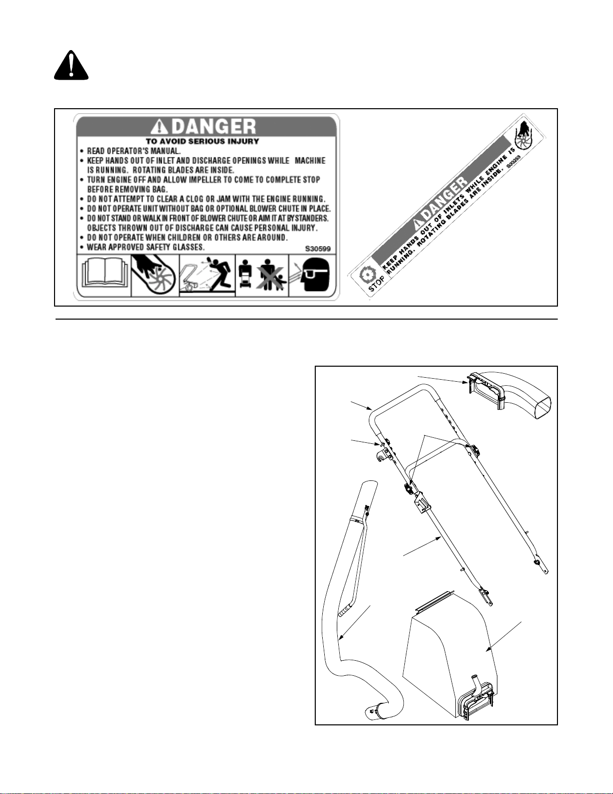
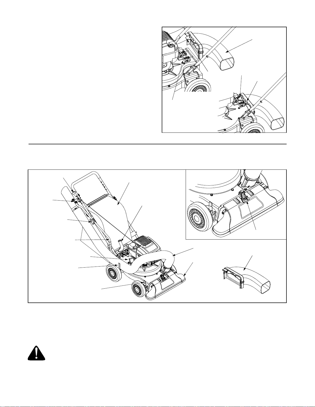
Loose Parts In Carton (See Figure 1)
• Handle Assembly
• Bag
• Blower Chute (If Equipped)
• Hose Assembly
Upper
Handle
Rope
Guide
Blower Chute
Wing
Nuts
Lower
Handle
Hose
Assembly
Bag
Disconnecting Spark Pl ug Wire
Before setting up your Yard Vacuum, disconnect the
spark plug wire from the spark plug and ground to a
stud on the engine.
Figure 1
5
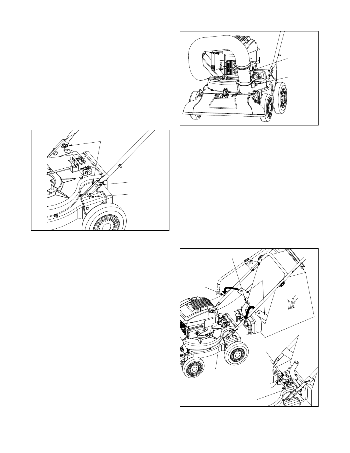
Attaching The Handle
• Unfold the upper handle until it aligns with the lower
handle.
• Secure the two handles by tightening the wing nuts
(carriage bolts must be seated properly into the
handle). See Figure 1
• Remove the hairpin clips from the handle brackets
on the Yard Vacuum and remove the carriage bolts
and wing nuts from the lower handle. See Figure 2.
• Place the bot tom holes i n lower handl e over pins on
handle brackets and secure with hairpin clips.
• Insert carriage bolts through upper hole in lower
handle from the outside and secure with wing nuts.
Wing Nuts
Carriage Bolt
Hairpin Clip
Hose
Adapter
Spring
Loaded Pin
Figure 3
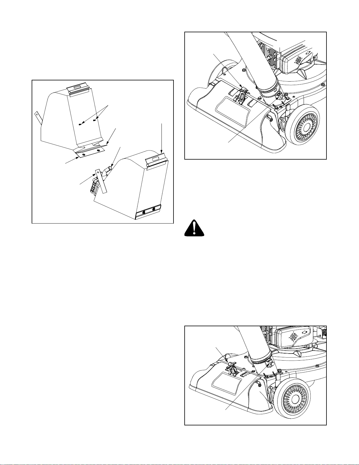
Attaching The Bag
• Grasp bag handle with one hand and slide locking
rod on mounting bracket with other hand toward
engine. Use the end of mounting bracket as
leverage when sliding the locking rod. See Figure 4.
• Slip bag over the rim of the discharge opening and
release locking rod to secure bag in place.
• Place the straps on the bag over the lower handle,
hooking them on the studs.
• Snap bag clip to the top of the lower handle.
Figure 2
• Loosen the wing nut that secures the rope guide to
the right side of upper handle.
• Pull the starter rope out of the engine slowly and
slip the starter rope into the rope guide. Tighten the
wing nut.
Attaching The Hose Assembly
• Slide hose adapter of hose assembly into the base
adapter located on the left front of the Yard
Vacuum. See Figure 3.
• Pull spring loaded pin out on the base and align pin
with the first hole in the hose adapter.
• Release the pin to lock the hose in place.
• Connect the hose handle near nozzle end of hose
to the side bracket on the upper handle. Refer to
Figure 6.
• Snap hose handle to the lower handle bracket to
secure in place and lay hose tubing on side bracket
hanger next to chipper chute. Refer to Figure 6.
NOTE: The safety switch button attached to the
mounting bracket mu st be fully dep ressed by the fr ont
tab on the bag handle when securing the bag or the
engine will not start.
Bag Handle
Straps
Stud
Front Tab
Locking
Rod
Stud
Figure 4
6
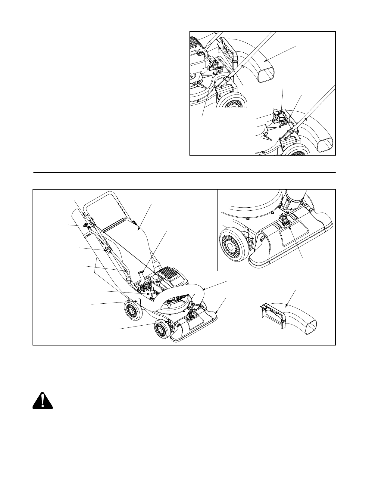
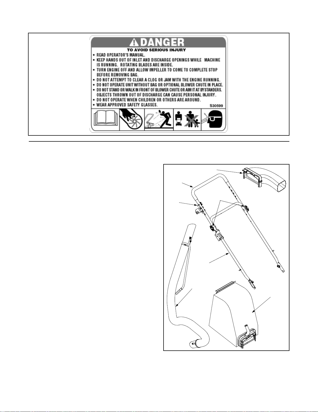
Attaching The Blower Chute (If Equipped)
• Grasp blower chute with one hand and slide locking
rod on mounting bracket with other hand toward
engine. Use end of mounting bracket as leverage
when sliding the locking rod. See Figure 5.
• Slip blower chute over rim of the discharge opening
and release locking rod to secure chute in place.
Make sure the safety switch button is fully
depressed by the front tab on the blower chute.
• Raise the nozzle height to the highest setting when
using the blower chute. Refer to nozzle height
adjustment in the OPERATION section.
Locking
Rod
SECTION 3: KNOW YOUR YARD VACUUM
Front
Tab
Figure 5
Front
Tab
Blower
Chute
Locking
Rod
Starter Handle
Side Bracket
Handle Bracket
Hose Handle
Chipper Chute
Side Hang er
Bracket
Nozzle Height
Adjustment Lever
Bag
Bag Handle
Figure 6
Read this operator’s manual and safety rules before
operating your Yard Vacuum. Compare the illustrations
in Figure 6 with your unit to familiarize yourself with the
location of various controls and adjustments.
WARNING: The operation of any Yard
Vacuum can result in foreign objects
being thrown into the eyes, which can
result in severe e ye d amage. Al ways wear
safety glasses, provided with the Yard
Vacuum, for operating this equipment or
while performing any adjustments or
repairs on it.
Nozzle/Hose
Vac Handle
Hose Assembly
Blower Chute
Nozzle
Starter Handle
The starter handle is attached to the right upper handle.
Stand behind unit and pull the starter handle to start
engine.
Bag
Collects shredded material fed through the chipper
chute or vacuumed through the nozzle or hose.
Bag Handle
Used to grasp bag in order to assist in attaching,
removing, and emptying bag.
7
Chipper Chute
Allow twigs and small branches up to 1 1/2” in diameter
to be fed into the impeller for chipping.
Blower Chute (If Equipped)
When attached to unit the blower chute is used to blow
or scatter yard waste such as leaves, pine needles, or
small twigs across yard.
Nozzle Height Adjustment Lever
Used to adjust the nozzle ground clearance ranging
approximately 5/8” to 4 1/8”.
Nozzle
Yard waste such as leaves or pine needles can be
vacuumed up through the nozzle for shredding.
Hose Handle
Used to guide hose assembly when vacuuming.
Nozzle/Hose Vac Handle
The nozzle/hose vac handle is located on top of the
nozzle and it is used to regulate the vacuum between
the nozzle and the hose assembly.
Throttle Control Lever (Not Shown)
The throttle control lever is located on the engine. It
controls the engine’s speed and stops the engine. See
separate engine manual packed with unit for details.
Engine Controls
See the separate engine manual for the location and
function of the controls on the engine.
Hose Assembly
Used as an alternative to the nozzle to vacuum yard
waste such as leaves or pine needles in hard to reach
places.
Stopping Engine
• Move throttle control lever to STOP or OFF
position.
• Disconnect spark plug wire from spark plug and
ground against the engine.
SECTION 4: OPERATING YOUR YARD VACUUM
WARNING: The operation of the Yard
Vacuum can result in foreign objects
being thrown into the eyes, which can
damage your eyes se verely. Always wear
the safety glasses provided with this unit
or eye s hield s bef ore ch ippi ng or b lowi ng
and while performing any adjustments or
repairs.
Gas And Oil Fill-Up
Service the engine with gasoline and oil as instructed in
the separate engine manual packed with your Yard
Vacuum. Read instructions carefully.
WARNING: Never fill fuel tank indoors with
engine running or until the engine has
been allowed to cool for at least two
minutes after running.
Starting Engine
• Attach spark plug wire to spark plug. Make certain
the metal cap on the end of the spark plug is
fastened securely over the metal tip on the spark
plug.
• Make sure safety swi tch wire is conne cted to
engine and properly grounded.
• Engines with choke lever:
Move choke lever on engine to CHOKE position. (A
warm engine may not require choking).
• Engines with primer:
Prime engine as instructed in separate engine
manual.
• The throttle control is located on the engine. Move
engine throttle control lever to FAST or ON position.
• Stand behind unit, grasp starter handle and pull
rope out slowly until engine reaches start of
compression cycle (rope will pull slightly harder at
this point).
• Pull rope with a rapid, continuous, full arm stroke.
Keep a firm grip on starter handle. Let rope rewind
slowly.
• Repeat previous steps until engine fires. When
engine starts, move choke control (if equipped)
gradually to RUN position.
WARNING: Never run the engine indoors
or in a poorly ventilated area. Engine
exhaust contains carbon monoxide, an
odorless and deadly gas.
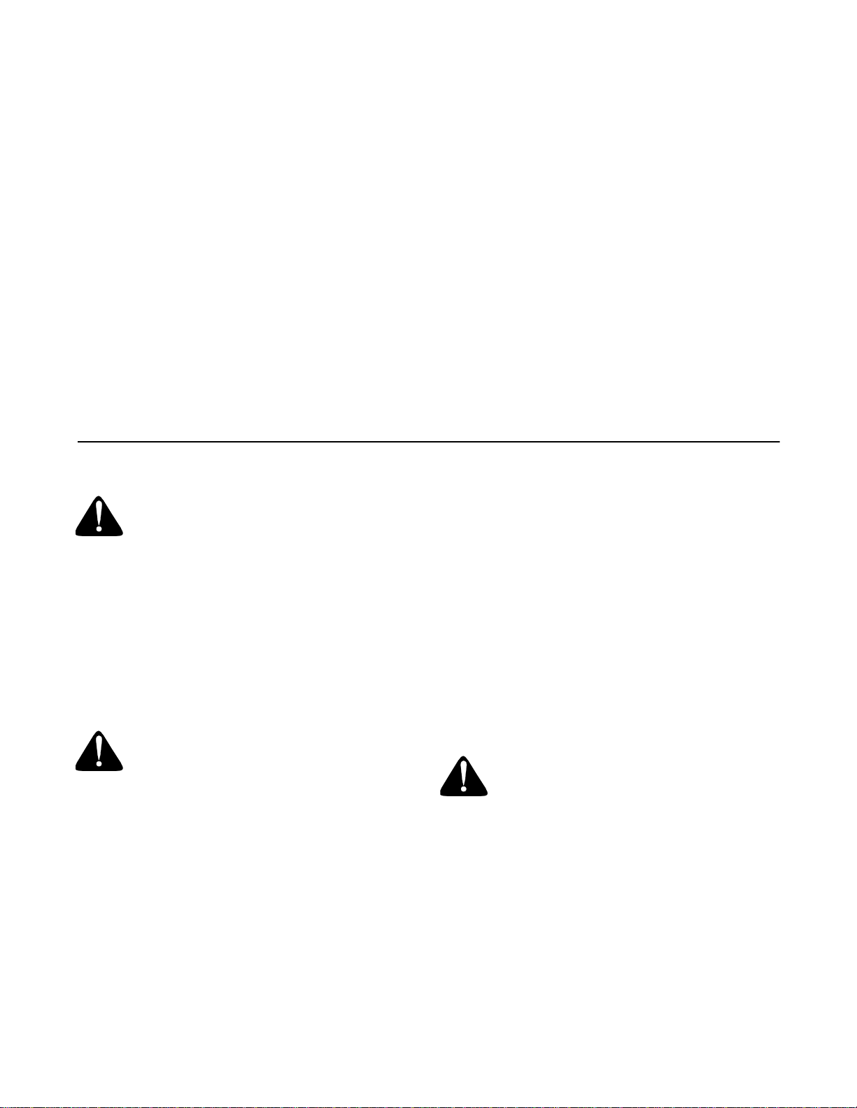
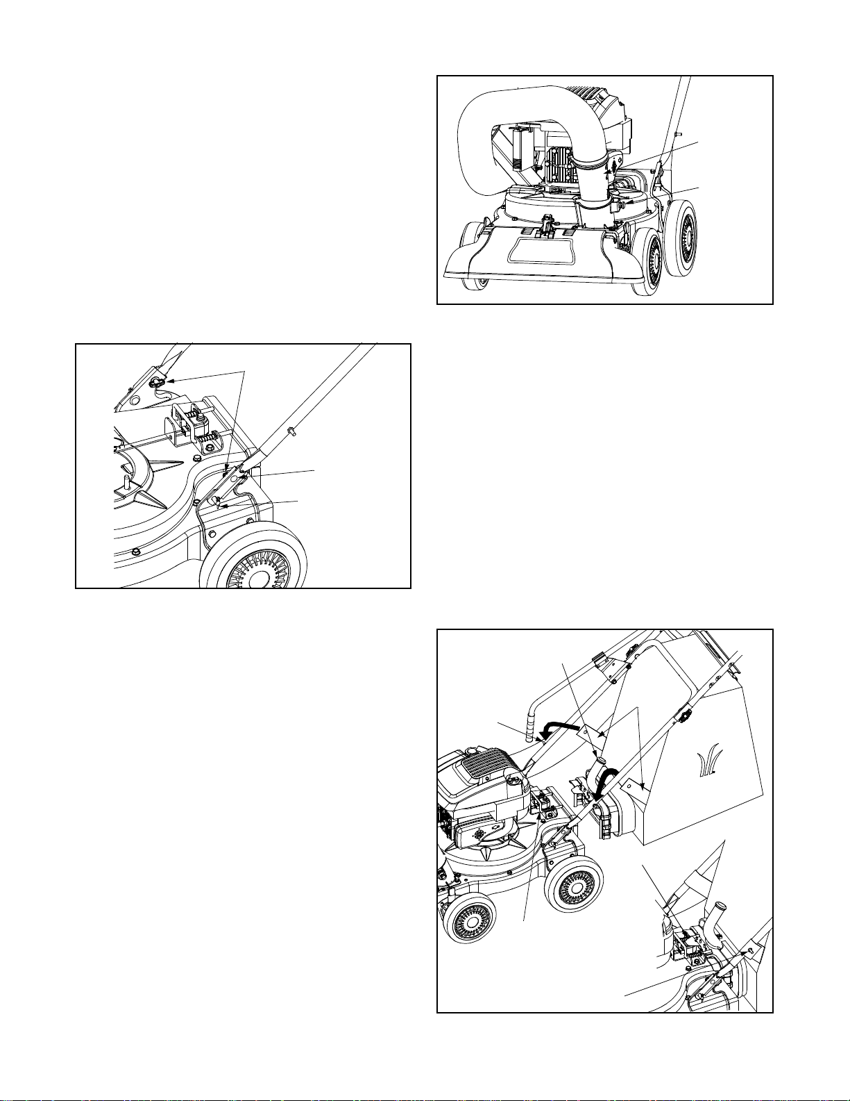
To Empty Bag
• Unhook bag straps from the lower handle and
unsnap bag clip from the top of lower handle.
See Figure 7.
• Grasp bag handle with one hand and pull lock rod
on mounting bracket with other hand toward engine
to release.
• Remove bag from rim of the discharge opening.
Refer to Figure 4.
• Twist the two buttons on the back of the bag to
unlock and empty contents. See Figure 7.
8
• Hold bag handle and bag clip while emptying the
contents.
• Compress bag opening and fold inner flap over
opening.
• Fold outer flap over inner flap and insert buttons on
the bag through metal outlets.
• Twist the buttons to lock bag.
Buttons
Nozzle/Hose
Vac Handle
(Top Position)
Inner Flap
Bag Clip
Bag Handle
Outer Flap
Strap
Figure 7
To Remove Blower Chute
• Grasp blower chute with one hand and pull lock rod
on mounting bracket with other hand toward engine
to release. Refer to Figure 5.
• Remove blower chute from rim of the discharge
opening.
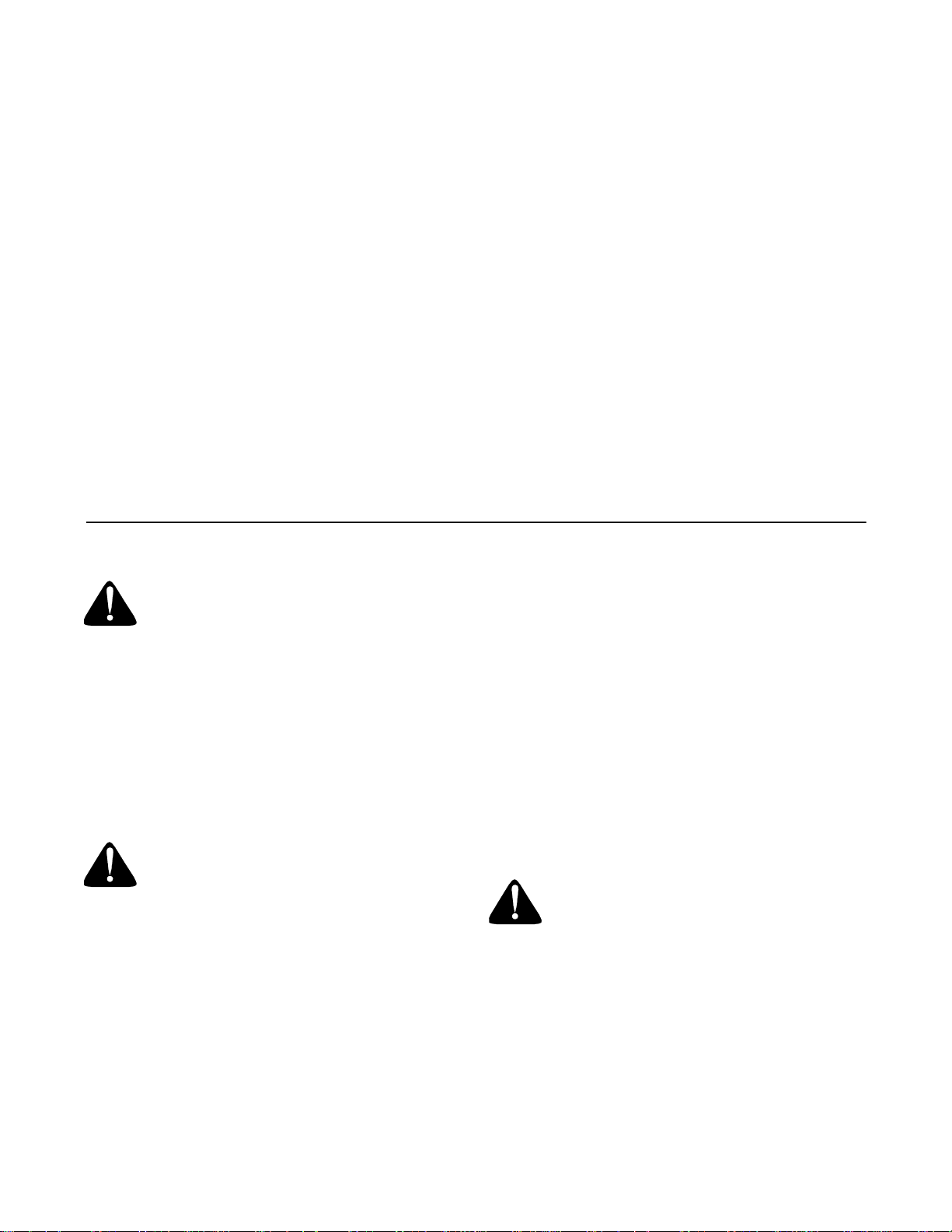
Using the Nozzle Vacu um
• Place nozzle/hose vac handle in the top position on
the nozzle to vacuum through nozzle. See Figure 8.
• The spring loa ded pin must be in the first h ole of the
hose adapter to operate the nozzle vac.
• Place both hands on top of upper handle to push
unit over yard waste.
Yard waste such as leaves and pine needles can be
vacuumed up through the nozzle for shredding. After
material has been shredded by the flail blades on the
impeller assembly, it will be discharged into catcher bag
or through blower chute. Do not attempt to shred or chip
any material other than vegetation found in a normal
yard (i.e. branches, leaves, twigs, etc.) Avoid fibrous
plants such as tomato vines until they are thoroughly
dried out. Materials such as stalks or heavy branches
up to 1 1/2” in diameter may be fed into the chipper
chute.
Spring Loaded Pin
(First Hole)
Figure 8
IMPORT ANT :
housing in the discharge area. If the flail screen
becomes clogged, remove and clean as instructed in
SECTION 5: MAINTAINING YOUR YARD VACUUM.
For best performance, it is also important to keep the
chipper blade sharp.
The flail screen is located inside the
WARNING: Do not at any time make any
adjustments without first stopping engine
and disconnecting spark plug wire.
Using the Hose Assembly
• Place nozzle /hos e vac h andl e in th e bot tom
position on the nozzle to redirect vacuum to the
hose assembly. See Figure 9.
• The spring loaded pin must be in the second hole of
the hose adapter to operate the hose assembly.
• Unhook the hose from upper handle bracket and
grasp the hose handle to guide while vacuuming
yard waste such as leaves or pine needles in hard
to reach places.
Nozzle/Hose
Vac Handle
(Bottom Position)
Spring Loaded Pin
(Second Hole)
Figure 9
9

Nozzle Height Adjustment
The nozzle can be adjusted to any six positions,
ranging from 5/8” to 4 1/8” ground clearance. The
nozzle height has to be adjusted according to the
conditions. Move the height adjustment levers forward
or backward to adjust the nozzle upwards or
downwards. See Figure 10.
NOTE: In general, r ai se th e nozzle height to v ac uum a
thick layer of leaves or to operate with the blower chute
and lower the nozzle height for smoother surfaces.
Nozzle
SECTION 5: MAINTAINING YOUR YARD VACUUM
Customer Responsibilities
s
s
r
r
u
o
h
0
0
1
y
r
e
c
n
O
MAINTENANCE
SCHEDULE
Lubricate Wheels
T
C
Lubricate Nozzle Levers
U
D
O
Lubricate Locking Rod
R
P
Lubricate Nozzle/Hose Handle
e
s
u
h
c
a
e
e
r
o
f
e
B
E
s
r
u
o
h
5
2
y
r
e
v
u
o
h
0
5
y
r
e
v
v
E
E
Nozzle Height
Adjustment
Lever
Figure 10
n
e
o
g
s
a
r
a
o
e
t
s
s
a
e
r
e
o
f
e
B
SERVICE
DATES
Check Chipper Blade
Change Oil
E
Check Air Filter
N
I
G
N
Clean Engine
E
Check Spark Plug
WARNING: Always stop engine and
disconnect spark plug wire before
cleaning, lubricating or doing any kind of
maintenance on your machine.
Lubrication
Wheels: Lubricate each wheel shoulder screw once a
season with light oil. Refer to Figure 6.
Nozzle height adjustment levers: Lubricate the pivot
points of the nozzle height adjustment levers once a
season with light oil. Refer to Figure 6.
Locking Rod: Lubricate the locking rod with light oil to
ease the application of attaching on or removing bag or
blower chute. Refer to Figure 6.
Nozzle/Hose Vac Handle: Lubricate the nozzle/hose
vac handle on top of nozzle once a season with light oil.
Refer to Figure 6.
Engine: Follow the separate engine manual packed
with you unit for lubrication instructions.
10

Maintenance
Engine
Refer to the separate engine manual for all engine
maintenance instructions.
• Check engine oil level before each use as
instructed in the separate engine manual packed
with your unit. Read and follow instructions
carefully.
• Clean air clea ner every 25 hours under normal
conditions or once a season. Clean every few hours
under extr emely dusty co nditions. To service th e air
cleaner, refer to the separate engine manual
packed with your unit.
• The spar k plug should be cleaned and the gap
reset once a season. Check engine manual for
correct plug type and gap specifications.
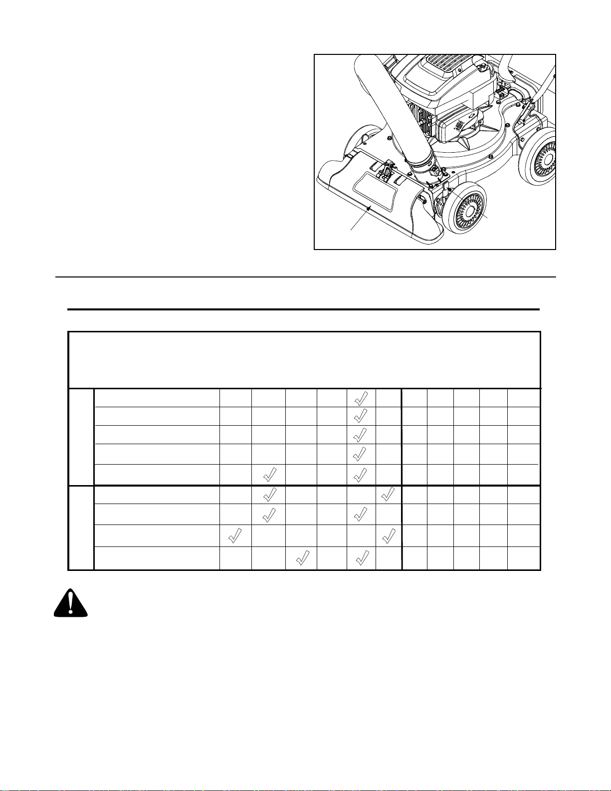
Removing The Flail Scr een
If the discharge area becomes clogged, remove the flail
screen and clean area as follows:
• Stop the engine and make certain the Yard
Vacuum has come to a complete stop.
• Disconnect spark plug wire from spark plug and
ground against the engine.
• Remove the bag or blower chute from the unit as
instructed in t he OPE RATIO N sec tion t o obt ain
access to flail screen. See Figure 11.
Hex Screw &
Flat Washer
Remove
Hex Screw
Figure 12
Sharpening Or Replacing Chipper Blad e
Because the engine on this unit has a tapered
crankshaft, a special impeller tool (part number 753-
0900) is required to remove the impeller assembly. For
further assistance, contact your local service dealer.
NOTE: When tipping the unit, empty the fuel ta nk and
keep spark plug side up.
• Disconnect the spark plug wire and ground it away
from the spark plug.
• Remove the front hubcaps, lock nuts, front wheels,
and wave washers that attach to the pivot arm
assemblies. See Figure 13.
• Remove the shoulder screws and bell washers that
go through the pivot arms and height bracket
adjusters to the front support brace.
Lock Nut
Figure 11
• Remove hex screw on right side of unit that
attaches to the fail screen. It may be necessary to
remove the hose bracket hanger to get access to
the hex screw. See Figure 12.
• Remove hex screw and flat washer on top of rear
housing mounting bracket and the lock nut that
secures flail screen. See Figure 11.
• Remove and clean the screen by scraping or
washing with water. Reinstall the flail screen.
Flail Screen
Pivot Arm Assembly
Bell Washer
Wave Washer
Height Adjustment
Bracket
• Remove the three screws on the upper housing
that secure the nozzle c over and th e nin e screws
that secure the lower housing to the upper housing.
See Figure 14.
11
Shoulder
Screw
Figure 13
Lock Nut
Hubcap

Housing
Screws
Nozzle
Screws
Lower Housing
Screws
• Apply lubricant to the threads of impeller removal
tool and then thread the tool into the crankshaft.
Stop when the impeller assembly can move on the
crankshaft.
• Remove the impeller assembly from the crankshaft.
Unthread the impeller removal tool from the
impeller assembly.
• Remove the blade using a 3/16” allen wrench on
the outside of the blade and 1/2” wrench on the
impeller assembly.
• Replace or sharpen chipper blade.
• When sharpening blade, protect hands by using
gloves and follow the original angle of grind.
• Reassemble by performing the previous steps in
reverse order.
• Tighten blade screws to 210-250 in-lbs.
Tighten impeller bolt to 375-425 in-lbs.
Figure 14
• Remove lock nut that secures flail screen to the
lower housing. The flail screen does not have to be
removed. Refer to Figure 11.
• Remove the hex bolt, lock washer, and flat washer
that secure the impeller assembly to the crankshaft.
See Figure 15.
Upper
Chipper
Blade
Housing
Impeller
Assembly
Hex Bolt
Lock Washer
Flat Washer
NOTE: Make certain chipper blade is reassembled with
the sharp edge facing upward. See Figure 16.
Flail
Blade
Chipper
Blade
Impeller
Assembly
Figure 16
Storing Y our Yard Vacuum
• Clean the equipment thoroughly.
• Wipe equipment with a oiled rag to prevent rust.
• Refer to engine manual for correct engine storage
instructions.
• Store unit in a clean, dry area. Do not store next to
corrosive materials such as fertilizer.
BOTTOM VIEW
Figure 15
Flail
Blade
12

SECTION 6: TROUBLESHOOTING
Problem Cause Remedy
Engine fails to start 1. Spark plug wire disconnected.
2. Fuel tank empty or stale fuel.
3. Throttle control lever not in correct
starting position. (If Equipped)
4. Choke not in CHOKE posit ion.
5. Blocked fuel line.
6. Faulty spark plug.
Engine runs er ratic 1. Spark plug wire loos e.
2. Unit running on CHOKE.
3. Blocked fuel line or stale fuel.
4. Water or dirt in fuel system.
5. Dirty air cleaner.
6. Carburetor out of adjustment.
Too much vibration 1. Loose parts or damaged impeller. 1. See authorized service dealer.
Engine overheats 1. Engine oil level low.
2. Dirty air cleaner.
3. Carburetor not adjusted properly.
Occasional skip (hesitates)
at high speed
Unit does not discharge 1. Discharge chute clogged.
Rate of discharge slows
considerably or
composition of discharged
material changes.
NOTE: For repairs beyond the minor adjustments listed above, contact your nearest authorized service dealer.
1. Spark plug gap too close. 1. Adjust gap to .030”.
2. Foreign object lodged in impeller.
3. Low engine RPM
4. Vacuum bag is full.
1. Low engine RPM.
2. Chipper blade dull.
1. Connect wire to spark plug.
2. Fill tank with clean, fresh gasoline.
3. Move throttle lever to FAST position.
4. Move choke to CHOKE position.
5. Clean fuel line.
6. Clean, adjust gap, or replace.
1. Connect and tighten spark plug wire.
2. Move choke lever (if equipped) to OFF
position.
3. Clean fuel line; fill tank with clean, fresh
gasoline
4. Drain fuel tank. Refill with fresh fuel.
5. Clean or replace air cleaner.
6. See authorized service dealer.
1. Fill crankcase with proper oil.
2. Clean or replace air cleaner.
3. See authorized service dealer.
1. Stop engine immediately and
disconnect spark plug wire. Clean flail
screen and inside of discharge opening.
2. Stop engine and disconnect spark plug
wire. Remove lodged object.
3. Always run engine at full throttle.
4. Empty bag.
1. Always run engine at full throttle.
2. Replace chipper blade or see your
authorized service dealer.
13

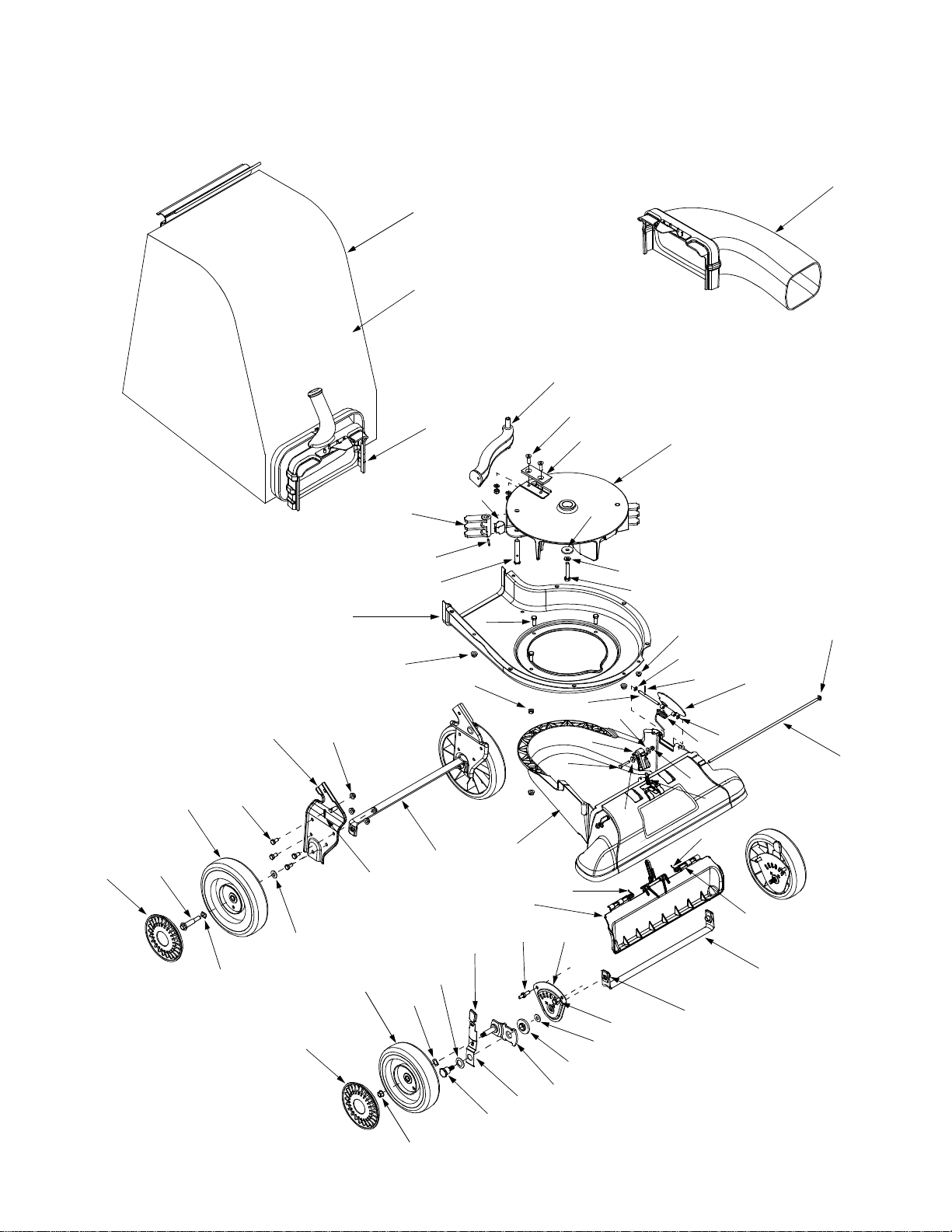
Model 24A-060F401
1
5
2
3
8
4
17
49
31
6
7
7
48
47
46
51
4
9
11
12
16
14
45
13
15
18
19
20
23
24
25
26
4
55
29
44
24
21
11
27
28
22
30
31
33
34
35
32
36
50
52
53
43
42
14
41
40
11
37
38
56
39
4
49
54

Model 24A-060F401
Ref.
No.
1. 720-0295 Foam Grip
2. 749-1423 Upper Handle
3. 720-0279 Knob
4. 712-3004A Flange Lock Nut 5/16-18
5. 710-1205 Eye Bolt
6. 781-1056 Upper Handle Bracket
7. 710-0528 Hex Cap Screw 5/16-18 x 1.25
8. 720-0314 Handle Knob 5/16-18
9. 710-1174 Carriage Bolt
11. 710-0604A Hex Washer Screw 5/16-18 x.625
12. 681-0174 Lower Handle Bracket
13. 749-0907B Lower Handle
14. 711-1293 Studs
15. 710-0703 Carriage Screw 1/4-20 x.75
16. 712-0397 Wing Nut 1/4-2 0
17. 731-1402B Shroud
18. 725-1700 Switch Cover
19. 725-3166 Safety Switch
20. 731-1613 Safety Switch Cover
21. 710-0224 Hex Wash er Screw #10-16 x.50
22. 629-0920 Wire Harness
23. 714-0104 Cotter Pin
24. 736-0264 Flat Washer.330 ID x.630 OD
25. 732-0962 Compression Spring
26. 781-0778A Mounting Bracke t
27. 747-1153 Lock Rod
28. 710-3195 Hex Cap Screw 5/16-18 x 4.5
29. 710-3025 Hex Cap Screw 5/16-18 x.625
Part No. Part Description
Ref.
No.
30. 710-0502A Hex Washer Screw 3/8-16 x 1.25
31. 710-0751 Hex Cap Screw 1/4-20 x .620
32. 731-2484 Hose Base Adapter
33. 716-0104 E Ring .500 Dia
34. 732- 303 5 Compressi on Sprin g
35. 711-1571 Clevis Pin
36. 736-3020 Flat Washer ..271 ID x .630 OD
37. 710-0969 Screw #12-16 x 1.0
38. 710-0425 Machine Screw #10 - 24 x .625
39. 781-1042 Upper Housing
40. 726-0454 U-Clip Lock Nut 5/16-18
41. 710-3008 Hex Cap Screw 5/16-18 x.75
42. 681- 012 2 Chipper Chute Assem bly
43. 738-1167 Stud 5/16-18 x .56
44. 736-0371 Flat Washer .343 ID x .880 OD
45. 781-1058 Hose Bracket Hanger
46. 712-3027 Hex Flange Nut 1/4-20
47. 748-0457 Spacer
48. 731-2478 Hose Nozzle
49. 710-3288 Hex Cap Screw 1/4-20 x 2.625
50. 723-0295 Adjustment Clamp
51. 749-1270 Nozzle Handle
52. 764-0648 Vacuum Hose
53. 07071 Handle Grip
54. 731-2292 Hose Adapter
55. 736-0607 External L-Washer 5/16
56. 712-0161 Hex Lock Nut #10 - 24
Part No. Part Description
NOTE: For painted parts, please refer to
the list of color codes below. Please add
the applicable color code, wherever
needed, to the part number to order a
replacement part. For instance, if a part
numbered 700-xxxx is painted Yard-Man
Green, the part number to order would be
700-xxxx-0665.
Yard-Man Green: 0665
Yard-Man Yellow: 0674
Powder Black: 0637
15
Model 24A-060F401
58
1
59
2
44
43
41
42
39
37
44
40
15
14
53
38
15
7
42
60
8
9
51
36
56
49
6
13
52
20
33
46
50
28
48
32
45
3
47
19
4
27
10
57
26
39
11
29
12
5
16
17
55
18
25
22
31
21
17
30
34
35
23
24
54
16

Model 24A-060F401
Ref.
No.
1. 664-0090 Bag Assembly
2. 681-0154 Screen Assembly
3. 710-1054 Hex Screw 5/16-24 x 1.0
4. 781-0490 Chipper Blade
5. 681-0152 Impeller Assembly
6. 781-0735 Pin Clip
7. 719-0329 Flail Blade
8. 715-0166 Spiral Pin
9. 711-1401 Clevis Pin
10. 736-0247 Flat Washer.375 ID x 1.25 OD
11. 736-0217 Lock Washer 3/8
12. 710-0818 Hex Cap Screw 3/8-24 x 2.0
13. 710-3038 Hex Cap Screw 5/16-18 x .875
14. 781-0721A Lower Housing
15. 712-3004A Flange Lock Nut 5/16-18
16. 712-3027 Hex Flange Nut 1/4-20
17. 736-0142 Flat Washer .281 ID x .50 OD
18. 714-0225 Cotter Pin
19. 711-1560 Pivot Rod
20. 731-2520 Nozzle
21. 781-1064 Base Adapter Door
22. 732-1156 Torsion Spring
23. 726-0106 Cap Speed Nut 1/4
24. 711-1551 Pivot Rod
25. 712-0161 Hex Lock Nut #10-24
26. 736-0400 Flat Washer .194 ID x .62 OD
27. 731-24 85 Nozzle Door Lever
28. 710-11 56 Hex Screw #10 -24 x 1.2 5
29. 750-1294 Shoul der Spacer
30. 732-3118 Extensi on Spring
31. 732-1151 Tors ion Spring LH
Part No. Part Description
Ref.
No.
32. 732- 1150 Torsion Sprin g RH
33. 731- 2294 Nozzle D oor
34. 711- 1582 Rod .25 x 1.25 Lg
35. 781- 072 5A Front Wheel Support Brace
36. 781- 077 7 Rear Wheel Supp ort Brace
37. 681-0155 Handle Bracket Ass”y LH
38. 714-0104 Cotter Pin
39. 710-3025 Hex Cap Screw 5/16-18 x.625
40. 736-0105 Bell Washer.401 ID x.870 OD
41. 734-1992 Wheel 9 x 2
42. 736-0232 Wave Washer .531 ID x .781 OD
43. 738-1015 Shoulder Screw 3/8-16
44. 731-1426 Hubcap
45. 781- 0785 Height Adjustme nt Bracket
46. 738- 1185 Stud 5/16-1 8 .56 x . 75
47. 741- 0751 Height Adjustme nt Bearing
48. 682- 0113 Pivot Arm Assembly
49. 720- 0426 Height Adjustme nt Knob
50. 732- 1026 Spring Lever
51. 736- 0741 Bell Wash er .760 ID x .25 OD
52. 738- 1173 Shoulder Screw .750 ID x .625 OD
53. 734-1978 Wheel 8 x 2
54. 712- 0431 Flange L ock Nut 3 /8-16
55. 726- 0453 Lock Nut 3/8 -16
56. 712- 0158 Hex Lock N ut 5/16-1 8
57. 736-0314 Thrust Washer .375 ID x .70 OD
58. OEM-290-012 Blower Chute (If Equipped)
59. 764-0507 Bag
60. 631-0083 Chute Assembly
Part No. Part Description
681-0156 Handle Brkt Ass”y RH (Not Sho wn)
17

Notes
18

ÍNDICE
Contenido Página
Medidas importantes d e seguridad................................................... ............ ................ ...20
Montaje de la aspirad ora para pati os........................................... ................. ................ ...22
Conozca las propi edades d e la aspirad ora para p atios................................ ................ ...24
Funcionamiento d e la aspirad ora para p atios.............................. ................. ................ ...25
Mantenimiento de la aspi radora para pa tios................................ ........... ................. ........27
Guía para la solució n de prob lemas.................................. ................ ................. .............. 30
Lista de las piezas....................................................... ...................... ....................... ........14
BÚSQUEDA DEL NÚMERO DE MODELO
Este manual de operació n es una parte importante de la nueva aspiradora para pa tios. Le ayudará a mont ar, preparar y
mantener la unidad para ob tener los m ejores res ultados. Por favor l ea y co mprenda e l contenido del man ual.
Antes de comenzar el monta je del equi po nuevo , por fav or encuentre la placa del mod elo del
equipo y copie l a informa ción con tenida en la mis ma en el espaci o provist o a co ntinuaci ón. La
información conte nida en l a placa del modelo es muy importan te en cas o de neces itar ayud a de
nuestro Departamento de Asist encia al Cliente o de un di stribuido r autori zado.
• Para encontrar el número de modelo mire hacia abajo de la parte posterior de la aspiradora para
patios. A continuación se explica un ejemplo de placa de modelo. Para referencias futuras, por favor
copie el número de modelo y el número de serie del equipo en el espacio a continuación.
(Número de modelo)
(Número de serie)
Copie el número del modelo en este espacio:
Copie el número de serie en este espacio:
MTD PRODUCTS INC
CLEVELAND, OHIO 44136
SERVICIO TELEFÓNICO DE ASISTENCIA AL CLIENTE
En caso de tener problemas para ens amblar e ste produ cto o de tener duda s con re spect o a los controles ,
funcionamiento o m anten imiento d el mism o, por fav or comu níquese c on el Dep artamento de asis tencia al cliente .
Llame al 1- (330) 220-4MTD (4 683) o 1- (800 )-800-7310 para c omunica rse con u n represe ntante de
asistencia al cli ente. Por favor cuan do ll ame tenga a la vi sta el nú mero de m odelo y el núme ro de serie
de su unidad. Consulte la sección anterior para ob tener esta información . Se le solicitará que ing rese el
número de serie para poder proce sar su llamada.
Si desea más información sobre la máquina visite nuestro sitio web en www.yardman.com
19

SECCIÓN 1: MEDIDAS IMPORTANTES DE SEGURIDAD
ADVERTENCIA: La presencia de este símbolo indica que se trata de instrucciones importantes de seguridad que
debe respetar para evitar poner en riesgo su seguridad personal y / o material y de otras personas. Lea y siga todas las
instrucciones contenidas en este manual antes de intentar poner esta máquina en funcionamiento. De no hacerlo puede
ocasionar lesiones. Cuando encuentre este símbolo - respete la advertencia que aparece a continuación del mismo.
ADVERTENCIA: El escape del mot or de este producto, algunos de sus compon entes y a lgunos
componentes del ve hículo conti enen o emiten productos q uímicos que el e stado de Calif ornia cons idera q ue
pueden producir cá ncer, defectos de nacimie nto u otro s prob lema s reprodu ctiv os.
PELIGRO: Esta máquina está diseñad a para se r utiliza da respet ando las reglas d e segurid ad conte nidas en
este manual. Al igua l que con todos l os equip os eléct ricos si el opera dor es de scuidado o come te errores puede
ocasionar lesiones graves. Esta máquina puede a mputar ma nos y p ies y arroja r objetos. De no r espetar la s
instrucciones de segurida d siguiente s se pue den p roducir le siones graves o la muerte .
CAPACITACIÓN
1. Lea, comprenda y respete todas las instruc ciones q ue
figuran en la máquin a o en e ste(os) m anual(es) antes de
proceder al monta je y operac ión del equi po. Guarde este
manual en un lugar seguro para referenc ias futuras y
regulares y para solic itar repuestos .
2. Familiarícese con todo s los controles y con el uso
adecuado de los m ismos. Sepa cómo detener l a
máquina y cómo desengr anar los control es rápida mente.
3. Nunca permita que niños m enores de 16 años operen
esta máquina. Lo s niños de 16 añ os y má s deb en leer y
comprender las ins truccione s de ope ración y las regl as
de seguridad cont enidas en este m anual y de ben ser
capacitados y superv isados por uno de los pad res.
4. Nunca permita que adulto s sin conocimient os acerca de
la máquina opere n la misma .
5. Mantenga a los o bservadores , ayudan tes, mas cotas y a
los niños por lo menos a 75 pies de la máquina mientras
la misma está en funcionami ento. Detenga la má quina si
alguien entra en l a zona.
6. Nunca encienda un motor en espacio s cerrados o en una
zona con poca ven tilación . El esca pe del m otor conti ene
monóxido de carbono, un gas inodoro y letal.
7. No ponga las man os o l os pies ce rca de las pie zas
rotatorias o en las cámaras de alimentación ni en la
abertura de descarga. El conta cto con el motor rotatorio
puede producir la amputac ión de de dos, ma nos o pie s.
8. Nunca trate de des tapar la to ma de al imentaci ón o la
abertura de descarga, ni trat e de sacar o vaciar la bolsa
de la aspiradora, ni de revis ar y repara r la máquin a
mientras el motor es tá en ma rcha. Apag ue el mo tor y
espere hasta que todas la s pieza s que se mueven se
hayan detenido p or completo . Desconec te el ca ble de l a
bujía y póngalo de manera que haga masa c ontra el
motor.
PREPARACIÓN
1. Revise minuciosam ente la zon a donde s e utiliz ará el
equipo. Retire todas las pi edras, bot ellas, l atas u otr os
objetos extraños qu e puedan ser le vantados o arrojados
causando lesiones o daños a la máquina.
2. Para protegerse los oj os utili ce siempre anteoj os o
antiparras de seguridad mient ras opera la máquina o
mientras la ajusta o repara. L os objet os arrojad os que
rebotan pueden lesionar gravemente la vista.
3. Utilice zapatos d e traba jo resisten tes, de s uela fuert e y
pantalones y ca misas a justados . Las pre ndas su eltas o
las alhajas pue den qued ar atrap adas en l as piez as
movibles. Nunca opere esta má quina estando descalzo o
con sandalias. Utilice g uantes de trabajo d e cuer o
cuando alimente m aterial po r el cana l de la cort adora.
4. Antes de encender la má quina co ntrole qu e todos l os
pernos y tornillos estén bie n ajusta dos para comproba r
que la máquina se encue ntra en c ondicion es segur as de
operación Además reali ce una inspecci ón visual de la
máquina a intervalos frecuen tes para controlar si la
misma está dañada .
5. Mantenga o reemplace las etiquetas de seguridad e
instrucciones según sea nece sario.
6. Sea sumamente cuid adoso al manipul ar la gas olina. La
gasolina es altamente inflamable y los vapores son
explosivos. Se puede lesio nar gravemente si derrama
gasolina sobre u sted o s obre la ro pa ya que se p uede
encender. Lave l a piel y cámbies e de ropa de inme diato.
a. Utilice sólo recipientes para gasolina autorizados.
b. Apague todos los cigarrillo s, cigarros, pipas y
otras fuentes de combust ión.
c. Nunca cargue combustible en la máquina en un
espacio cerrado.
d. Nunca saque la tap a del gas ni agreg ue
combustible mien tras el moto r está ca liente o en
marcha.
e. Deje que el motor se e nfríe por l o menos dos
minutos antes d e volve r a cargar combust ible.
f. Nunca recargue el tanque de combu stible. L lene
el tanque no má s de 1/2 pulgada p or deb ajo de la
base del cuello del fil tro para dejar espaci o para la
dilatación del combustible.
g. Vuelva a colocar l a tapa de la gaso lina y a jústela
bien.
h. Limpie la gasoli na derrama da so bre el mo tor y el
equipo. Traslade la máqu ina a otra zona. Es pere
5 minutos antes de encende r el motor.
i. Nunca almacene la máquina o el recip iente de
combustible en un espaci o cerrado donde hay a
fuego, chispas o l uz pilot o (por ejem plo, horn os,
calentadores de ag ua, calefactores, sec adores de
ropa, etc.)
j. Para reducir el riesg o de incend io ma ntenga la
máquina limpia de past o, hoja s y de acumulac ión
de otros escombros. Limpie los derrames de
20

aceite o combusti ble y sa que todos los
escombros embebi dos con combus tible.
k. Deje que la máquina se enfr íe por lo menos 5
minutos antes de guardarla.
FUNCIONAMIENTO
1. No ponga las man os o l os pies ce rca de las pie zas
rotatorias o en las c ámaras de ali mentación ni en la
abertura de descarga. El conta cto con el motor rotatorio
puede producir la amputac ión de de dos, ma nos o pie s.
2. Antes de encender la máquina comprue be que el canal
de la cortadora, l a toma de aliment ación y la cámara de
corte están vacías y sin escombros.
3. Inspeccione minuc iosamen te todo e l materia l que des ea
triturar y saque lo s obj etos met álicos, pie dras, botell as,
latas u otros objetos extraños que puede n ocasiona r
lesiones o dañar la máquina.
4. Si el motor golpea un objeto extraño o si la máquina
produce un sonido poco común o una vibración al
encenderla, apagu e el mot or de inm ediato. Dej e que el
motor se detenga por comp leto. De sconect e el cab le de
la bujía, póngalo de manera q ue haga m asa co ntra el
motor y siga estos pasos:
a. Inspeccione la má quin a pa ra v er s i est á da ñad a.
b. Repare o reemplace las piezas dañadas.
c. Controle si hay piezas f lojas y ajústela s para
asegurar que la máq uina funcione de ma nera
segura y continua.
4. No permita que se acumule m aterial pro cesado en la
zona de descarga. El mismo puede ob staculizar la
descarga adecuada y prov ocar el r etorno del material a
través de la abertura de alim entación.
5. No intente triturar ni picar m aterial de mayor tama ño al
especificado en l a máquina o en este man ual. Se podrían
producir lesiones o daños.
6. Nunca trate de des tapar la t oma de a limentación o la
abertura de descarga mie ntras el motor e stá en marc ha.
Apague el motor y espere hasta que todas la s piezas que
se mueven se hay an deteni do por co mpleto, d esconec te
el cable de la b ujía y póng alo de m anera que haga mas a
contra el motor antes de sacar los escombros.
7. Nunca opere la máquina sin que la bol sa de la
aspiradora y el canal de descarga estén conecta dos a la
máquina como corresp onde. Nu nca vacíe ni ca mbie la
bolsa de la aspirad ora mientras el motor es tá en marcha.
El extremo con cierre de la b olsa de la aspiradora debe
quedar cerrado todo el tiempo mientras la máqu ina está
en funcionamiento.
8. Nunca ponga la m áquina en funcion amiento s i el pic o de
ingreso o la uni ón opcional para la m anguera n o están
conectados a la máq uina adecuadamente. N unca intente
conectar o cambi ar ninguna de esta s uniones mie ntras el
motor está en marcha.
9. Mantenga todos los protectores, desviad ores y
dispositivos de segurid ad en su lugar y en buenas
condiciones.
10. Mientras alimenta material dentro de la máquina
mantenga su rost ro y su c uerpo det rás y hac ia un
costado del cana l de la cortadora para evitar lesi ones por
retrocesos acciden tales.
11. Nunca op ere esta m áquina s in buena visibi lidad o
iluminación. Siempre debe estar seguro de qu e está bien
afirmado y soste nga bien las manijas .
12. No opere e sta máquin a en supe rficies con gr ava.
13. No opere e sta máquin a estando bajo los efectos del
alcohol o de drogas.
14. El silen ciador y el motor se cali entan y produce n una
quemadura. No los toque.
15. Nunca le vante o transpo rte la máquina cuando el motor
está encendido.
MANTENIMIENTO Y ALMACENAMIENTO
1. Nunca manipule los dispositivos de s eguridad de manera
imprudente. Controle periódicamente que funcionen de
forma adecuada.
2. Controle frecuentem ente que todos los pernos y tornillos
estén bien ajustado s para c omprobar q ue la máquina se
encuentra en con diciones seguras de operaci ón.
Además realice una inspecci ón visual de la máquina
para controlar si la misma est á dañada y repárela de ser
necesario.
3. Antes de limpiar, reparar o inspecci onar la máquina,
detenga el motor y compruebe que e l mismo y todas las
partes que se mueven se hallan detenido. Desconec te el
cable de la bujía y póngalo de mane ra que hag a masa
contra el motor para evitar que se enc ienda de manera
accidental.
4. No cambie la configuración del regulador del motor ni
acelere demasiado el mism o. El regulador control a la
velocidad máxima segura d e operac ión del motor.
5. Mantenga o reemplace las etiquetas de seguridad e
instrucciones según se a necesario.
6. Siga las instrucc iones d e este manu al par a cargar,
descargar, transportar y almac enar de manera segura
esta máquina.
7. Nunca almace ne la máquina o el recipiente de
combustible en un espacio cerrado d onde haya f uego,
chispas o luz piloto com o por ejem plo, cal entadores de
agua, hornos, secad ores de ropa, etc.
8. Consulte siempre el manual de ope ración para las
instrucciones adecua das para el almacen amiento fuera
de temporada.
9. Si debe vaciar el ta nque de c ombusti ble, hágalo al aire
libre.
10. Respete l as norma s referente s a la d isposición correcta
y las reglam entaciones sobre gas , combus tible, etc. para
proteger el medio am biente.
ADVERTENCIA: - SU RESPONSABILIDAD:
Sólo permita que usen esta máquina eléctrica
las personas que lean, comprendan y respeten
las advertencias y las instrucciones que
aparecen en este manual y en la máquina.
NOTA: Es posible que no todas las etiquetas de seguridad
que se enseñan correspon dan a es ta cortado ra triturado ra.
21
SECCIÓN 2: MONTAJE DE LA ASPIRADORA PARA PATIOS
IMPORTANTE: Esta un idad se envía sin gas olina ni ace ite en
el motor. Antes de op erar la máquina cargue el motor con
gasolina y ace ite como se indi ca en el manu al separa do del
mismo.
NOTA: Las referenc ias a l os lado s derec ho o iz quierd o de la
aspiradora para patios se hacen observando la máquina
desde la posición de opera ción.
Extracción de la unidad de la caja
• Saque las grapas, rompa el pegamento de las aletas
superiores o corte la cinta del extremo de la caja tire a lo
largo de la aleta superior par a abrir la caja.
• Saque las piezas sueltas qu e se inc luyen junto con la
unidad (es deci r, el manual de operac ión, et c.)
• Corte a lo largo de las esqu inas, extie nda la caja plana
hacia abajo y saque el materi al de embalaje.
• Haga rodar o deslice la uni dad fue ra de la caja y re vise
minuciosamente l a caja p ara contro lar si hay piez as
sueltas.
Canal de soplado
Superior
Manija
Cuerda
Guía
A mariposa
Tuercas
Inferior
Manija
Piezas sueltas en la caja (Ver Figura 1)
• Montaje de la manija
• Bolsa
• Canal de soplado (Si está i ncluido)
• Montaje de la manguera
Desconexión del cable de la bujía
Antes de instalar l a aspirad ora para p atios des conecte el
cable de la bujía de la misma y póngalo de mane ra que ha ga
masa con un perno del motor.
Manija
Montaje
Bolsa
Figura 1
22
Montaje de la manija
• Despliegue la manija supe rior hasta que que de alinea da
con la manija inferior.
• Para sujetar las dos manij as ajust e las tue rcas de
mariposa (los pernos del carro deben estar colocado s de
forma adecuada en l a manija). Ve r Figura 1
• Saque los broches de horqu illa de l os sopo rtes de la
manija de la aspi radora para patios y saque los pernos
del carro y l as tuerca s de mar iposa de la ma nija infe rior.
Ver Figura 2.
• Coloque los agujeros inferi ores de l a manija inferior
sobre los pernos de los soport es de la manija y
asegúrelos con broches de orquilla.
• Inserte los pernos del carro desde el lado de afuera a
través del agujero s uperior d e la manija inferior y
asegúrelos con tuercas de m aripo sa.
Manguera
Adaptador
Resorte
Perno con
Figura 3
Tuercas de
mariposa
Bulón del carro
Broche de
horquilla
Figura 2
• Afloje la tuerca de maripos a que so stiene la guía de la
cuerda contra el lado dere cho de l a manija superior.
• Tire despacio de la cuerda del arran cador hac ia afuera y
deslice la cuerda del arrancado r dentro de la guía para la
cuerda. Ajuste la tuerca a marip osa.
Instalación del montaje de la manguera
• Deslice el adaptador para manguera del montaj e de la
misma hacia el i nterior del adaptado r base ub icado a la
izquierda y al frent e de la a spiradora para patios. Ver
Figura 3.
• Tire del perno con resorte del l ado exte rior de la base y
ponga el perno en línea con el primer agujero del
adaptador para ma nguera.
• Suelte el perno para ajustar la manguera en su lugar.
• Conecte la manija de la m anguera ub icada c erca del
extremo con pico de la misma al soporte lateral de la
manija superior. C onsulte Fig ura 6.
• Una a presión la manija de la m anguera c on el so porte
de la manija inferi or para aj ustarla en su luga r y coloque
el caño de la manguera en el g ancho de l soporte la teral
que se encuentra próximo al cana l de la c ortadora.
Consulte Figura 6.
Colocación de la bolsa
• Sostenga la manija de la bolsa con un a mano y deslice la
varilla de segurida d del soporte d e montaj e hacia el
motor con la otra m ano. Use e l extremo de l soporte de
montaje como p alanca cua ndo desl ice la v arilla de
seguridad. Ver Figura 4.
• Deslice la bolsa por enci ma del b orde de la abertu ra de
descarga y suelte la varil la de se guridad pa ra ajusta r la
bolsa en su lugar.
• Coloque las tiras de la bolsa por encima de la manija
inferior enganchándola s en los pernos.
• Una el broche de la bolsa a presi ón con la p arte supe rior
de la manija inferi or.
NOTA: El bo tón del interrup tor de seguridad unido al soporte
de montaje debe quedar presionado totalmente por la aleta
delantera de la manija de la bo lsa cuando ajuste la bols a o el
motor no arrancará.
Manija de
la bolsa
Tiras
Perno
Aleta delantera
De seguridad
Varilla
23
Perno
Figura 4
Instalación del canal de soplado(Si está
Frente
Aleta
De soplado
Canal
De seguridad
Varilla
incluido)
• Tome el canal de soplado con una mano y deslice la
varilla de segurida d del soporte d e montaj e hacia el
motor con la otra m ano. Use e l extremo de l soporte de
montaje como p alanca cua ndo de slice l a varilla de
seguridad. Ver Figura 5.
• Deslice el canal de sopl ado po r encima del borde de la
abertura de descarga y su elte la varilla de segurid ad para
ajustar el canal en su luga r. Comp ruebe que el bot ón del
interruptor de seguridad que de presionado tota lmente
por la aleta dela ntera del canal de soplado .
• Aumente la altura del pico al máximo cuando utilice el
canal de soplado. C onsulte las i nstrucciones para ajustar
la altura del pico en la sección FUNCIONAMIENTO.
Frente
Aleta
De seguridad
Varilla
Figura 5
SECCIÓN 3: CONOZCA LAS PROPIEDADES DE LA ASPIRADORA PARA
PATIOS
Manija del arrancador
Bolsa
Soporte
lateral
Manija de la bolsa
Soporte de
la manija
Manija de
la manguera
Canal de
la cortadora
Gancho lateral
Soporte
Altura del pico
Palanca de ajuste
Lea este manual de operación y las reglas de seguridad
antes de poner la a spiradora para patio s en func ionamiento .
Compare las ilus traciones en Figu ra 6 con su unida d para
familiarizarse con la ubic ación de los dis tintos c ontrole s y
ajustes. Guarde es te manua l para refe rencias futuras.
ADVERTENCIA: Al operar la aspiradora para
patios puede ser que objetos extraños sean
arrojados a los ojos lo cual puede dañarlos
gravemente. Utilice siempre los anteojos de
seguridad provistos con la aspiradora para
patios para operar el equipo o mientras lo
ajusta o lo repara.
Pico / Manguera
Manija de la aspiradora
Montaje de la manguera
Canal de soplado
Pico
Figura 6
Manija del arrancador
La manija del a rrancador est á unid a a la m anija su perior
derecha. Para encender el motor párese detrás de la unidad y
tire de la manija del arrancador .
Bolsa
Junta el material t riturado que ingre só a trav és del can al de
picado o que fue a spirado a través d el pico o de la man guera.
Manija de la bolsa
Se utiliza pa ra toma r la bols a para colocar la, sa carla y
vaciarla.
24
Canal de la cortadora
Permita que las ramas peque ñas de hasta 1 1/2” de diámetro
ingresen al motor para picarlas.
Canal de soplado (Si está incluido)
Cuando se lo une a la uni dad el c anal de s oplado s e utiliz a
para soplar o esparcir por los patios los desechos que se
acumulan en lo s mismos como por ejem plo las hojas, l as
agujas de los p inos o l as ramas pequeñas.
Palanca de ajuste de la altura del pico
Se utiliza para ajus tar la di stancia entre el suel o y el p ico que
varía aproximadamente de 5/8” a 4 1/8”.
Pico
Los desechos que se ac umulan en los p atios co mo por
ejemplo las hojas o las aguja s de los pinos se pueden aspirar
con el pico para picarlos.
Montaje de la manguera
Se usa como alterna tiva del uso del pico par a aspirar los
desechos que se acumulan en los patios como por ejemplo
las hojas o las a gujas de los pin os que s e encuen tran en
lugares de difícil ac ceso.
Manija de la manguera
Se utiliza para g uiar el m ontaje de la mang uera mientras se
aspira.
Manija del pico / manguera de la aspiradora
La manija del p ico / mangu era de la aspirado ra se enc uentra
en la parte supe rior del pi co y se utiliza para regu lar la
aspiración entre el pico y el montaje de la manguera.
Palanca de contro l del regu lador (No se enseña)
La palanca de control del regulador está ubicada en el motor.
Controla la velocidad del motor y lo detiene. Si desea más
detalles, consu lte el m anual del motor que v iene por
separado y emba lado co n la unid ad.
Controles del moto r
Consulte el manu al del m otor que v iene por separado si
desea conocer la ubicación el funcionamie nto de los
controles del motor.
Detención del motor
• Mueva las palancas de control del regulador a la posición
STOP (detención) u OFF ( apagado).
• Desconecte el cable de la bujía y póngalo de m anera que
haga masa contra e l motor.
SECCIÓN 4: FUNCIONAMIENTO DE LA ASPIRADORA PARA PATIOS
ADVERTENCIA: Al operar la aspiradora para
patios puede ser que objetos extraños sean
arrojados a los ojos lo cual puede dañarlos
gravemente. Utilice siempre los anteojos de
seguridad provistos con esta unidad o
protectores para ojos antes de pica r o soplar el
material y mientras realiza ajustes o
reparaciones.
Carga de gas y aceite
Cargue el motor co n gasoli na y aceite com o se ind ica en e l
manual separado del mis mo que viene em balado c on la
aspiradora para patios. Lea cuidadosamente las
instrucciones.
ADVERTENCIA: Nunca cargue el tanque de
combustible en espacios cerrados con el
motor en marcha o hasta que haya dejado que
el mismo se enf ríe por lo menos dos minutos
después de haber estado en marcha.
Encendido del motor
• Conecte el cable de la bujía a la misma. Com pruebe q ue
la tapa metálica del extremo de la bujía esté bien
ajustada sobre l a punta m etálica de la bujía.
• Compruebe que el cable del interrupto r de segu ridad
esté conectado al motor y que haga descarga a tierra
como corresponde.
• Motores con palanca de obturación:
Mueva la palanca de obturación del motor a la p osición
CHOKE (obturación). (Si el motor está t ibio la o bturación
puede no ser neces aria).
• Motores con cebador:
Utilice el cebador del motor como se explica en el manual
por separado del motor.
• El control del regulador está ubicado en el motor. M ueva
las palancas de c ontrol de l regulad or del mo tor a la
posición FAST (rápido) o START (encendido).
• Párese detrás de la unidad, tome la manija del
arrancador y saque cuerda le ntamente hasta que el
motor alcance el comienzo del ciclo de compresión (la
cuerda tirará un poco más fuerte en este punto).
• Tire de la cuerda de manera rápida y continua. Ap riete
bien la manija del arrancad or. Deje que la soga se
enrosque lentamente .
• Repita los pasos anteriores hasta que se encie nda el
motor. Cuando se enciende el motor m ueva el control d e
obturación (si está incluido) gradualmente hasta la
posición RUN (en marcha).
ADVERTENCIA: Nunca encienda el motor en
espacios cerrados o en una zona poco
ventilada. El escape del motor contiene
monóxido de carbono, un gas inodoro y letal.
Descarga de la bolsa
• Desenganche las tiras de la bolsa de la manija infe rior y
desabroche el br oche de la bolsa de la pa rte superi or de
la manija inferior.
Ver Figura 7.
• Tome la manija de la bolsa con una mano y tire de la
varilla de segurida d del soporte d e montaj e hacia el
motor con la otra m ano para sol tarla.
• Saque la bolsa del borde de la abertu ra de des carga.
Consulte Figura 4.
25

• Gire los dos botones de la parte posterior de la bolsa
para abrirla y va ciar el c ontenido . Ver Figura 7.
• Sostenga la manija y el broche de la bolsa mientras vac ía
el contenido.
• Comprima la abertura de la b olsa y dobl e la ale ta interior
sobre la abertura.
• Doble la aleta exterior sobre la aleta interior e inserte los
botones de la bolsa a través de las salidas metálicas.
• Gire los botones para cerrar la bolsa.
Botones
Broche de
la bolsa
Aleta interior
hasta 1 1/2” de diámetro en el canal de la co rtadora.
Pico / manguera
Manija de la aspiradora
(Posición superior)
Manija de
la bolsa
Aleta exterior
Tira
Figura 7
Extracción del canal de soplado
• Tome el canal de soplado con una mano y tire de la
varilla de segurida d del soporte d e montaj e hacia el
motor con la otra m ano para sol tarlo. Co nsulte Figu ra 5.
• Saque el canal de soplado del borde de la ab ertura de
descarga.
Uso del pico de la aspiradora
• Coloque la manija del pic o / mangu era de la aspirado ra
en la posición superior del pico para aspirar a t ravés del
mismo. Ver Figura 8.
• El perno con resorte debe estar en el primer agu jero de la
adaptación de la manguera para ope rar el pico de la
misma.
• Coloque ambas manos en l a parte superior de la ma nija
superior para des plazar la unidad por encim a de los
desechos acum ulados e n el pati o.
El desecho que se acum ula en l os patios c omo por ejemplo
las hojas y las agujas d e los pi nos pued en asp irarse a través
del pico para triturarlos. Desp ués que ha triturado el material
con las hojas de desgranar de l montaje del motor, el mi smo
será descargado a la bol sa colec tora o a través del can al de
soplado. Sólo utilice la máquina para triturar o picar el
material integrante de la vegetación que se encuentra en un
patio normal (es decir, ramas, hojas, ramas pequeñas, etc.)
Evite las plantas fibrosas como por ejemplo las de tomates
hasta que estén totalmen te secas. Se pueden i ntroducir
materiales como p or ejemplo t roncos o ramas pe sadas d e
Perno con resorte
(Primer agujero)
Figura 8
IMPORTANTE: La pantalla de desgrana do est á ubicada
dentro de la caja en la zona de descarga. Si se tapa la
pantalla de desgranad o, sáquela y límp iela como se indica en
SECCIÓN 5: MANTENIMIENTO DE LA ASPIRADORA
PARA PATIOS. Para obtener el mejo r resultado e s
importante también mantener afilada la hoja de la corta dora.
ADVERTENCIA: Siempre detenga el motor y
desconecte el cable de la bujía antes de realizar
cualquier ajuste.
Uso del montaje de la manguera
• Coloque la manija del pic o / mangu era de la aspirado ra
en la posición de la base del pico para volver a dirigir la
aspiración al montaje de la manguera. Ver Figu ra 9.
• Para operar el ensamblado de la mang uera, el perno con
resorte debe estar en el segu ndo aguje ro del ad aptador
de la misma.
• Desenganche la manguera de l soporte de la m anija
superior y tome la manija de la manguera para dirigirla
mientras aspira los desechos que se acumulan en los
patios como po r ejemplo hojas o agujas de pinos que se
encuentran en lu gares de dif ícil acceso.
Pico / manguera
Manija de la aspiradora
(Posición de la base)
Perno con resorte
(Segundo agujero)
Figura 9
26
Ajuste de la altura del pico
Puede ajustar el pico en seis posic iones que varían desde 5/
8” a 4 1/8” de dis tancia d el suelo . Debe a justar la al tura de l
pico según las condiciones. Mueva las pala ncas para ajustar
la altura hacia adelante o hacia a trás para ajustar el pico
hacia arriba o ha cia abaj o. Ver Figu ra 10.
NOTA: En general, levante la altura del pico para aspirar
una capa gruesa de hojas o para usar el canal de soplado y
baje la altura de l pico p ara las sup erficies más lisas .
Pico
Figura 10
SECCIÓN 5: MANTENIMIENTO DE LA ASPIRADORA PARA PATIOS
Responsabilidades del cliente
s
s
a
r
r
a
0
0
1
a
d
o
o
p
h
a
z
d
e
a
v
r
o
a
n
U
t
e
t
p
n
m
A
e
a
n
e
i
l
m
e
a
d
n
s
e
c
a
m
l
MANTENIMIENTO
PROGRAMACIÓN
O
Lubrique las ruedas
T
C
Lubrique las palancas del pico
U
D
O
Lubrique la varilla de seguridad
R
P
Lubrique la manija del pico / manguera
s
a
r
e
d
o
s
s
u
e
t
a
n
d
A
a
c
o
h
5
2
a
d
a
C
r
o
h
0
5
a
d
a
a
C
C
o
t
Altura del pico
Ajuste
Palanca
CONTROL
FECHAS
Controle la hoja de la cortadora
Cambie el aceite
R
Controle el filtro de aire
O
T
O
Limpie el motor
M
Controle la bujía
ADVERTENCIA: Detenga siempre el motor y
desconecte el cable de la bujía an tes d e limpiar
y lubricar la máquina o de realizar todo tipo de
mantenimiento de la misma.
Lubricación
Ruedas: Lu brique los torn illos con rebord e de las rueda s una
vez por temporada c on acei te liviano. Consul te Figura 6 .
Palancas de ajuste de la altura del pico: Lubrique lo s
puntos giratorios de las palanc as de ajuste de la altura del
pico una vez por t emporada con a ceite livia no. Con sulte
Figura 6.
Varilla de seguridad: Lubriqu e la varilla de segu ridad con
aceite liviano para faci litar l a aplica ción para colo car y sa car
la bolsa del cana l de sop lado. Co nsulte Fi gura 6.
Manija del pico / mang uera de la a spiradora: Lubrique la
manija del pico / manguera de la as piradora d e la parte
superior del pico una vez por temporada con aceite liviano.
Consulte Figura 6.
Motor: Siga las instruccion es de lu bricación del manual
separado del mo tor que vi ene emb alado co n la unid ad.
Mantenimiento
Motor
Consulte el manu al separa do del m otor para c onocer toda s
27

las instruccio nes de m antenimi ento del mismo.
• Controle el nivel de aceite del motor antes de cada uso
como se indica e n el man ual sepa rado del m ismo que
viene embalado con la uni dad. Lea y siga las
instrucciones cui dadosam ente.
• Limpie el depurador de aire cada 25 horas en
condiciones normales o una vez por temporada. Limpie a
intervalos de po cas hora s cuando haya m ucho pol vo.
Para realizar el cont rol del de purador de aire con sulte el
manual separado del mot or que vi ene emba lado con la
unidad.
• La bujía debe lim piarse y se debe reponer la dist ancia
disruptiva una vez por temp orada. Cons ulte el m anual
del motor para conocer las especificaciones para el tipo
de bujía y para la distancia dis ruptiva.
Extracción de la pantalla de desgranad o
Si la zona de de scarga se t apa, saqu e la pant alla de
desgranado y limpie la zo na como se indica a con tinuación:
• Detenga el motor y comprueb e que la aspirado ra para
patios se haya detenido por comp leto.
• Desconecte el cable de la bujía y póngalo de mane ra que
haga masa contra e l motor.
• Saque la bolsa o el canal de sopl ado de la unida d como
se indica en la sección de FUNCIONAMIENTO para
acceder a la pantal la de de sgrana do. Ver Figu ra 11.
Tornillo de cabeza hexagonal y
Arandela plana
Tuerca de seguridad
Figura 11
• Saque el tornillo de cabez a hexagon al del l ado derec ho
de la unidad que se une a l a pant alla de des granado. Es
posible que nec esite saca r el ganc ho del s oporte de la
manguera para acce der al torn illo de c abeza h exagonal .
Ver Figura 12.
• Saque el tornillo de cabez a hexagon al y la arandela
plana de la parte superior del soporte de monta je de la
caja posterior y la tuerca de segurid ad que un e la
pantalla de desgranado . Ver Figura 11.
• Saque la pantalla y límpiela con un c epillo o lávela co n
agua. Vuelva a colo car la pa ntalla de desg ranado.
Pantalla de
desgranado
Saque
Tornillo de
cabeza
hexagonal
Figura 12
Afilado o recambio de las hojas de la
cortadora
Debido a que el motor de esta unidad tiene un cigüeñal
ahusado, se nece sita una herramie nta para mo tores especial
(pieza número 753-0900) pa ra sacar el montaj e del motor. Si
necesita más ayuda comu níquese c on el di stribu idor de s u
zona autorizado para reali zar el mant enimi ento.
NOTA: Cuando incline la unidad, vacíe el tanque de
combustible y ma ntenga el lado de la bu jía hacia arriba.
• Desconecte el cable de la bujía y conéctelo a ti erra lejos
de la misma.
• Saque las tapas de buje de lanteras, las tuerc as de
seguridad, las r uedas del anteras y las ara ndelas
ondulatorias que van uni das a lo s montaj es del b razo
giratorio. Ver Figura 13 .
• Saque los tornillos con rebord e y las arandelas de
campana que pasa n por los brazos g iratorios y los
adaptadores de los soportes de altura hasta la traba de
sostén delantera.
Montaje del brazo giratorio
Arandela de campana
Ajuste de la altura
Soporte
Con reborde
Tornillo
Tuerca de
seguridad
Figura 13
• Saque los tres tornillos de la caja su perior que unen la
cubierta del pico y los nu eve torni llos que unen la caja
inferior a la superior. Ve r Figura 14 .
Arandela
ondulatoria
Tapa del
28
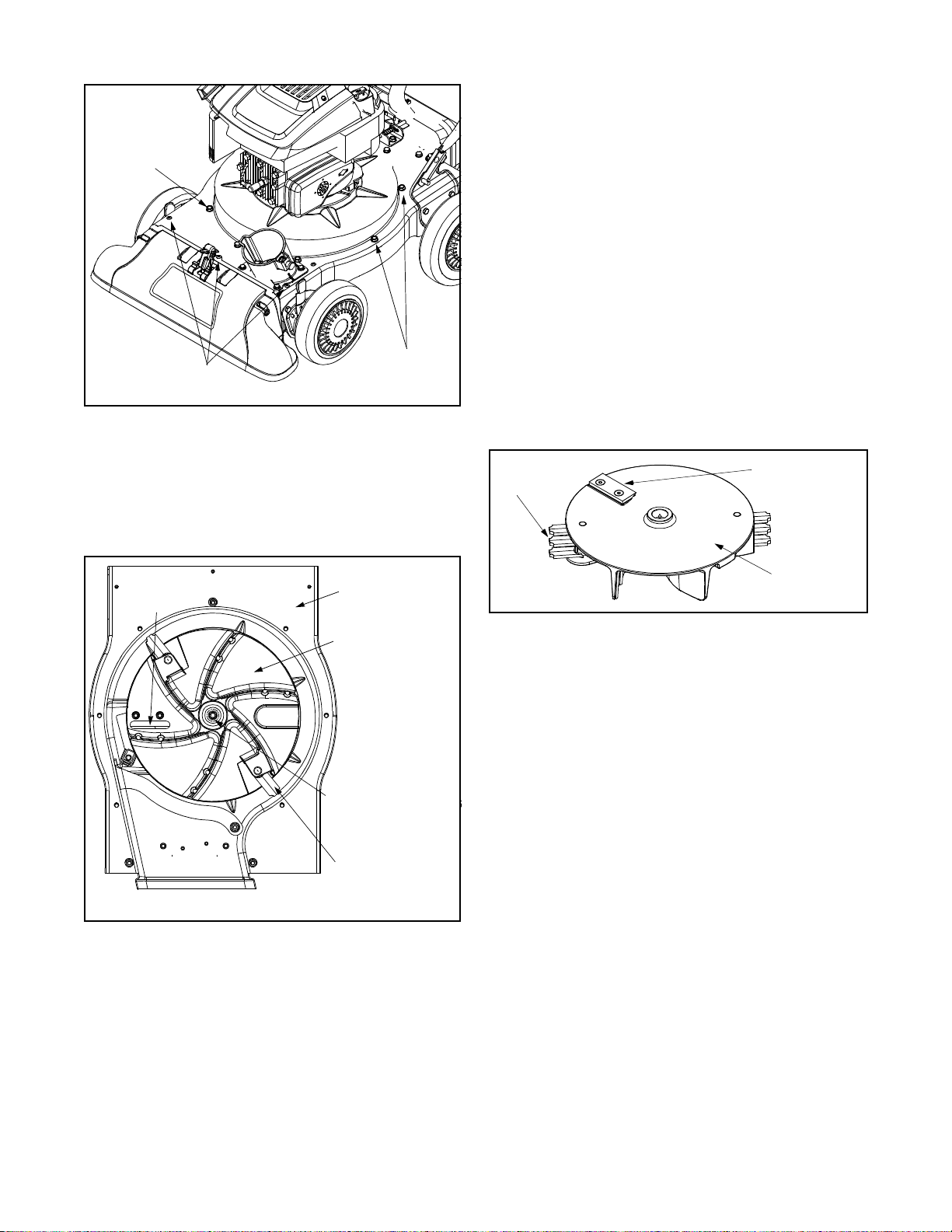
Caja
a
Tornillos
Caja inferior
Pico
Tornillos
Tornillos
Figura 14
• Saque la tuerca de seguridad que une la pantalla de
desgranado a la caja inf erior. No es nece sario sacar la
pantalla de desgranado. Consulte Figura 11.
• Saque el bulón hexagonal, la arandela de seguridad y la
arandela plana q ue unen e l montaj e del mo tor al
cigüeñal. Ver Figura 15.
• Aplique lubricante a las rosc as de la herramienta que se
usa para sacar el motor y luego enrosque la herramienta
en el cigüeñal. Deténgase cuando el montaje del motor
se pueda mover en el ci güeñal.
• Saque el montaje del motor del cigüeñal. Desenrosque
del montaje del motor la herramien ta que se utiliza para
sacarlo.
• Saque la hoja mediante el uso de una lla ve allen de 3/16 ”
en el lado exter ior de la hoja y d e una lla ve de 1/ 2" en el
montaje del motor.
• Cambie o afile las hojas de la cortadora.
• Cuando afile las hojas, protéjase las ma nos med iante e l
uso de guantes y siga el ángulo original de molido.
• Para realizar el reensamblado siga los pasos anteriores
pero en orden inverso.
• Ajuste los tornillos de la ho ja con u n par de to rsión de
210-250 in-lbs.
Ajuste el perno del motor con un par de torsión de 375425 in-lbs.
NOTA: Compruebe que se reensamblen las hojas de la
cortadora con el filo hacia arriba. Ver Figura 16.
De desgranar
Hoja
Cortadora
Hoja
Cortadora
Hoja
VISTA DE LA BASE
Figura 15
Superior
Caja
Motor
Montaje
Bulón hexagonal
Arandela de segurid
Arandela plana
De desgranar
Hoja
Motor
Montaje
Figura 16
Almacenamiento de la aspiradora para
patios
• Limpie el equipo por completo.
• Limpie el equipo con un trapo con aceite para evitar que
se oxide.
• Consulte el manual del motor para conocer las
instrucciones para el al macenam iento co rrecto del
mismo
• Almacene la unidad en una zona li mpia y seca. N o la
almacene cerca de material es corrosiv os como p or
ejemplo fertilizant es.
29

SECCIÓN 6: GUÍA PARA LA SOLUCIÓN DE PROBLEMAS
Problema Causa Solución
El motor no arranca 1. Se ha desconecta do el ca ble de la bujía.
2. El tanque de combus tible está vacío o el
combustible es viejo.
3. La palanca de contr ol del regulado r no
está en la posic ión de arran que
correcta. (Si está inclu ida)
4. La palanca de ob turación no está en la
posición CHOKE (obturación).
5. La línea del combustible está
bloqueada.
6. La bujía no funciona correctamente.
El motor funciona de manera
errática
Demasiada vibra ción 1 . Hay partes que están flojas o el motor
El motor recalienta 1. El nivel de aceite del motor es bajo.
Saltos ocasionales (dud a) a
alta velocidad
La unidad no desc arga 1. El canal de descarga está ta pado.
Tasa de descarga se reduce
de manera considerable o
cambia la composición del
material descargado.
1. El cable de la bu jía está flojo.
2. La unidad está funcionando en la
posición CHOKE (obturación).
3. La línea del combustible está tapada o
el mismo es viej o.
4. Agua o suciedad en el sistema del
combustible.
5. El depurador de aire está sucio.
6. Es necesario ajusta r el carbur ador.
está dañado.
2. El depurador de aire está sucio.
3. El carburador no es tá ajustado
correctamente.
1. La distancia disruptiv a de la bujía es
muy poca.
2. Hay un objeto ext raño en el motor.
3. RPM del motor son bajas
4. La bolsa de la aspiradora está llena.
1. RPM del motor son bajas.
2. La hoja de la cortadora está desafilada.
NOTA: Si debe realizar reparaciones más importantes que las enunciadas anteriormente comuníquese con el distribuidor
autorizado para el mantenimiento más cercano.
1. Conecte el cable a la bujía.
2. Llene el tanque con gaso lina lim pia y fre sca.
3. Mueva la palanca del regulador a la posición
FAST (rápido).
4. Ponga la palanca de obturaci ón en la
posición CHOKE (obturación).
5. Limpie la línea del combustible .
6. Límpiela, ajuste la dist ancia di sruptiva o
cámbiela.
1. Conecte y ajuste el ca ble de l a bujía.
2. Cambie la palanc a de obtu ración (si está
incluida) a la pos ición OFF ( apagado).
3. Limpie la línea del combustible ; llene e l
tanque con gaso lina lim pia y fre sca
4. Vacíe el tanque del combustibl e. Vuelva a
llenarlo con co mbustibl e fresco.
5. Limpie o cambie el depurador de aire.
6. Consulte al distribuidor autorizado para el
mantenimiento.
1. Consulte al distribuidor autorizado para el
mantenimiento.
1. Llene el cárter con aceite adec uado.
2. Limpie o cambie el depurador de aire.
3. Consulte al distribuidor autorizado para el
mantenimiento.
1. Ajuste la distancia disrupti va a 0,03 0”.
1. Detenga el motor d e inmedi ato y
desconecte el cab le de la bujía . Limpie la
pantalla de desgran ado y el interior d e la
abertura de descarga.
2. Detenga el motor y descon ecte el c able de
la bujía. Saque el objeto extraño del motor.
3. Siempre accione el motor co n el regul ador
al máximo.
4. Vacíe la bolsa.
1. Siempre accione el motor co n el regul ador
al máximo.
2. Cambie la hoja de la cortadora o consulte al
distribuidor autoriz ado para e l
mantenimiento.
30

GARANTÍA LIMITADA DEL FABRICANTE PARA:
La garantía limitada que se extiende a continuación es
otorgada por la empresa MTD PRODUCTS INC (“MTD”) con
respecto a mercader ías nu evas co mpr ada s y utiliza das en l os
Estados Unidos, sus posesiones y territorios .
MTD garantiza este producto por defectos materiales y de
fabricación por un período de dos ( 2) años a partir de la fecha
de la compra original y reparará o cam biará sin cargo cuan do
lo considere pertinente todas las piezas con defectos
materiales o de fabric ación. Esta garantía limitada sólo será
aplicable si el producto ha sido utilizado y mantenido según lo
establecido en el Manual de operación provisto j unto con el
producto y no ha sufrido usos inadecuados, abuso, usos
comerciales, descuidos, accidentes, mantenimiento
incorrecto, alteraciones, vandalismo, robo, incendio, agua
producto de otros peligros o desastres naturales. El daño
resultante por la instalación o el uso de acces orios o uniones
no aprobados por MTD Products Inc. para su us o con el(los)
producto(s) incluido(s) en este manual anulará la garantía en
lo que respecta a esos daños.
Las piezas o componentes desgastables normales están
sujetos a condiciones diferentes como se indica a
continuación: Todas las fallas de las piezas o componentes
desgastables norm al es estarán cubiertas par a el producto po r
un período de 90 días sin importar la causa. Después de los
90 días, pero dentro del per íod o de dos año s, la s fallas de l as
piezas desgastables normales serán cubiertas SOLO SI
fueron causadas por los defectos materiales o de fábrica de
OTRAS piezas componentes. Las piezas o componentes
desgastables norma les incluy en pero no se limitan a correas,
hojas, adaptadores para hojas, bolsas para pasto, ruedas para
la plataforma, asientos, zapatos anti deslizantes para la
máquina de sacar nieve, placas y gomas de corte. Las
baterías están cubiertas por una garantía de reposición
limitada de 90 días.
OBTENCIÓN DEL SERVICIO DE MANTENIMIENTO: El
servicio de la garantía está disponible, CON PRUEBA DE
COMPRA A TRAVÉS DEL DISTRIBUIDOR LOCAL
AUTORIZADO PARA EL MANTENIMIENTO. Para ubicar al
distribuidor de su zona, por favor controle si existe una lista en
las Páginas amarillas o comuníquese con el Departamento de
asistencia al cliente de MTD PRODUCTS INC llamando al 1800-800-7310 o escribiendo al apartado postal P.O. Box
368022, Cleveland, Oh io 44136-9722.
Esta garantía limitada no lo cubrirá en los siguientes
casos:
a. El motor y las piezas componentes presentes. Estos
artículos tienen una garantía diferente a cargo del
fabricante. Por favor para estos artículos consulte la
garantía aplicable del fabricante.
b. Las bombas para el corte de madera, las válvulas y los
cilindros tienen una garantía independiente de un año.
c. Los artículos ne cesarios par a el man tenimient o de ruti na
como por ejemplo lubrica ntes , filtros, afilador es de hoj as,
las adaptaciones y los ajustes como por ejemplo los
ajustes de los frenos, de l embrague o d e la plataforma y
el deterioro norma l del acabado exterior debido al uso o
exposición.
d. MTD no extiende ninguna garantía para los productos
vendidos o exportados fuer a de los Estados Unidos de
América, sus posesiones y territorios, excepto para
aquellos vendidos a través de los canales autorizados de
distribución de exportacio nes de MTD.
No se aplican garantías impl ícitas, incluidas las garan tías
implícitas de comerciabilidad o de adecuación para un
propósito determinado, después del período de
aplicación de la garantía escrita expresa extendida más
arriba para las piezas de acuerdo con su identificación.
Ninguna otra garantía expresa, ora l o escrita, excepto la
mencionada anteriormente, extendida por personas o
personas jurídicas, incluidos los distribuidores o los
minoristas con respec to a los prod uctos obligará a MTD.
Durante el plazo de la garantía el único recurso es la
reparación o reemplazo del producto como se indicó
anteriormente. (Algunos estados no permiten las limitaciones
a la duración de las garantías implícitas por lo que la limitación
antes mencionada puede no serle de aplicaci ón. )
Las disposiciones incluidas en esta garantía proveen el
recurso único y exclusivo que surge de las ventas. MTD
no será responsab le por pérdidas o daños inciden tales o
directos, incluyendo sin límites los gastos incurridos para
los servicios de cuidado del pasto de reemplazo o
cambio, los gastos de transporte o los gastos
relacionados, o los gastos de alquiler para reemplazar de
manera transitoria un producto bajo garantía. (Algunos
estados no perm iten la exclusión o limitación de los dañ os y
perjuicios incidentales o dire ctos, por lo que las limitaciones
mencionadas anter i orm e nt e pueden no serle de aplicaci ón.)
En ningún caso se obtendrá una compensación mayor al
monto del precio de compra del producto vendido. La
alteración de las características de seguridad del producto
anularán esta garantía. Usted asume el riesgo y la
responsabilidad por las pérdidas, da ños o lesiones que s ufra
Usted y sus biene s y / o otras personas y s us bienes como
consecuencia del uso, del uso i nc orrecto o de la im posibilidad
de uso de este producto.
Esta garantía limitada alcanza solamente al comprador
original, al arren datario original o a la persona que recibi ó el
producto de regalo.
Relación de la ley estadual con esta garantía: Esta garantía
limitada le otorga derechos legales específicos y puede
también contar con otros derecho s que varía n de un estado a
otro.

MANUFACTURER’S LIMITED WARRANTY FOR:
The limited warranty set forth below is given by MTD
PRODUCTS INC (“MTD”) with respect to new mercha ndise
purchased and used in the United States, its possessions
and territories.
MTD warrants this product against defects in material and
workmanship for a period of two (2) years commencing on
the date of original purc ha se an d w i ll, at its option, repai r or
replace, free of charge, any part found to be defective in
material or workmanship. This limited warranty shal l only
apply if this product has been operated and maintained in
accordance with the Operator’s Manual furnished with the
product, a nd has not bee n subj ect to misuse, abuse, commercial use, neglect, accident, improper maintenance,
alteration, vandalism, theft, fire, water or damage because
of other peril or natur al di sa ste r. Damage resulting from the
installation or use of any accessory or attachment not
approved by MTD Products Inc. for use with the product(s)
covered by this manual will void your warranty as to any
resulting damages.
Normal wear parts or components thereof are subject to
separate terms as follows: All normal wear part or component failures will be covered on the product for a period of
90 days regardless of cause. After 90 days, but within the
two year period, normal wear part failures will be covered
ONLY IF caused by defects in material or workmanship of
OTHER component parts. Normal wear parts and components include, but are not limited to, belts, blades, blade
adapters, grass bags, rider deck wheels, seats, snow
thrower skid shoes, shave plates and tires. Batteries are
covered by a 90-day limited replacement warranty.
HOW T O OBTAIN SERVICE: W arr anty service is a v aila b le ,
WITH PROOF OF PURCHASE THROUGH YOUR LOCAL
AUTHORIZED SERVICE DEALER. To locate the dealer in
your area, please check for a listing in the Yellow Pages or
contact the Customer Service Department of MTD PRODUCTS INC by calling 1-800-800-7310 or writing to P.O. Box
368022, Clev e land, Ohio 44136-9722.
This limited warranty does not provide coverage in the
following cases:
a.The engine or component parts thereof. These items
carry a separate manufacturer’s warranty. Please refer
to the applicable manufacturer’s warranty on these
items.
b.Log splitter pumps, valves and cylinders have a sepa-
rate one year warr an ty.
c. Routine maintenance items such as lubricants, filters,
blade sharpening and tune-ups, or adjustments such
as brake adjustments, clutch adjustments or deck
adjustments; and normal deterioration of the ex terior
finish due to use or exposure.
d. MTD does not extend any warranty for products sold
or exported outside of the United States of America,
its possessions and territories, except those sold
through MTD’s authorized channels of export distribu-
tion.
No implied warranty, including any implied warranty of
merchantability or fitness for a particular purpose,
applies after the applicable period of express written
warranty above as to the par ts as ident ified. No o ther
express war ranty or guaranty, whether wri tten or or al,
except as mentioned above, given by any person or
entity, including a dealer or retailer, with respect to any
product shall bind MTD. During the period of the Warranty, the exclusive remedy is repair or replacement of
the product as set forth above. (Some states do not
allow limitations on how long an implied warranty lasts, so
the above limitation may not apply to you.)
The provisions as set f orth in this W a rranty pr o vide the
sole and exclusive remedy arising from the sales. MTD
shall not be liable for incidental or consequential loss
or damages including, without limitation, expenses
incurred for substitute or replacement lawn care services, for transportation or for related expenses, or for
rental expenses to temporarily replace a warranted
product. (Some states do not allow the exclusion or limita-
tion of incidental or consequential damages, so the above
exclusion or limitation may not apply to you.)
In no event shall recover y of any kind be greater than the
amount of the purchase price o f the pro duct sold . Alter ati on
of the safety features of the product shall void this Warranty. You assume the risk and liability for loss, damage, or
injury to you and your property and/or to others and their
property arising out of the use or misuse or inability to use
the product.
This limited warranty shall not extend to anyone other than
the original purchaser, original lessee or the person for
whom it was purchased as a gift.
How State Law Relates to this Warranty: This limited
warranty gives you specific legal rights, and you may also
have other rights which vary from state to stat e.
 Loading...