

Page 1

YaRD'MaNi]//
OPERATOR'S MANUAL
Riding Mower
Internal Bagging System
27.5" Cutting Deck
Model 247.270170
Factory No. 13A-325-402
IMPORTANT: READ SAFETY RULES AND INSTRUCTIONS CAREFULLY
Warning: This unit is equipped with an internal combustion engine and should not be used on or near any unimproved forest-
covered, brush-covered or grass-covered land unless the engine's exhaust system is equipped with a spark arrester meeting
applicable local or state laws (if any). If a spark arrester is used, it should be maintained in effective working order by the operator.
In the State of California the above is required by law (Section 4442 of the California Public Resources Code). Other states may have
similar laws. Federal laws apply on federal lands. A spark an'ester for the muffler isavailable through your nearest engine authorized
service dealer or contact the service department, P.O. Box 368022 Cleveland, Ohio 44136-9722.
MTD PRODUCTS INC. P.O. BOX 368022 CLEVELAND, OHIO 44136-9722
PRINTED IN U.S.A. FORM NO, 770-10201
(12/98)
Page 2
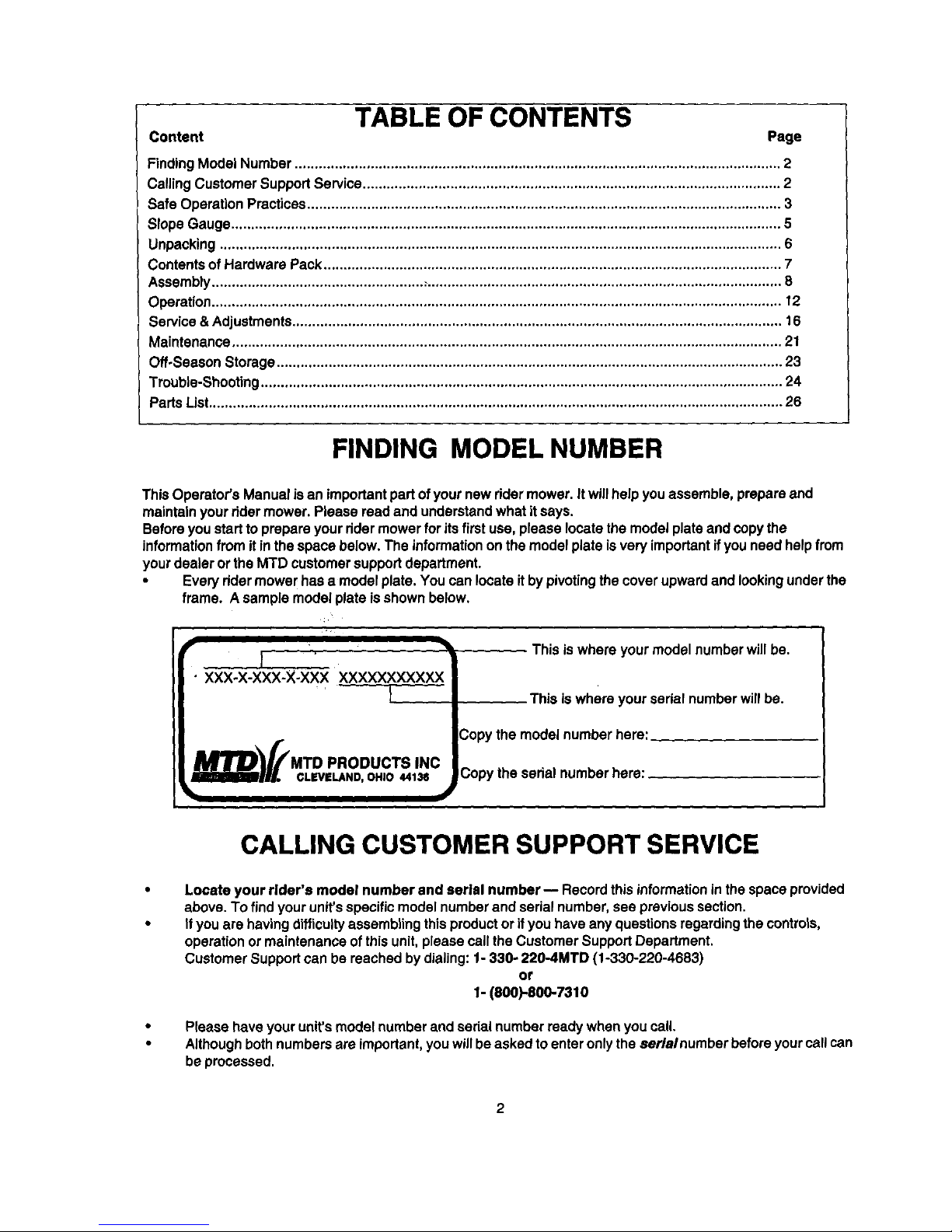
TABLE OF CONTENTS
Content Page
Finding Model Number .......................................................................................................................... 2
Calling Customer Support Service ......................................................................................................... 2
Safe Operation Practices ....................................................................................................................... 3
Slope Gauge .......................................................................................................................................... 5
Unpacking ............................................................................................................................................. 6
Contents of Hardware Pack ................................................................................................................... 7
Assembly ..................................................... ;......................................................................................... 8
Operation ............................................................................................................................................... 12
Service & Adjustments........................................................................................................................... 16
Maintenance .......................................................................................................................................... 21
Off-Season Storage ............................................................................................................................... 23
Trouble-Shooting ................................................................................................................................... 24
Parts List................................................................................................................................................ 26
FINDING MODEL NUMBER
This Operator's Manual is an important part of your new rider mower. Itwill help you assemble, prepare and
maintain your rider mower. Please read and understand what it says.
Before you start to prepare your dder mower for itsfirst use, please locate the model plate and copy the
information from itin the space below. The information on the model plate is very important ifyou need help from
your dealer or the MTD customer support department.
• Every rider mower has a model plate. You can locate it by pivoting the cover upward and lookingunder the
frame. A sample model plate isshown below.
This is where your model number will be.
PRODUCTSINC
This is where your serial number will be.
Copy the model number here:
Copy the serial number here:
CALLING CUSTOMER SUPPORT SERVICE
Locate your rlder's model number and serial number -- Record this informationin the space provided
above. To find your unit's specific model number and sedal number, see previous section.
If you are having difficultyassembling this product or ifyou have any questions regarding the controls,
operation or maintenance of this unit, please call the Customer Support Department.
Customer Support can be reached by dialing: 1- 330- 220-4MTD (1-330-220-4683)
or
1- (800)-800-7310
Please have your unit's model number and serial number ready when you call.
Although both numbers are important, you will be asked toenter only the $erlalnumber before yourcall can
be processed.
Page 3
SAFE OPERATION PRACTICES
This symbol points out important safety instructions which, ifnot followed, couldendangerthe per-
sonalsafety and/or propertyof yourselfand others. Read and follow all instructionsinthismanual before
attemptingto operate your ridermower. Failure to complywiththese instructionsmay result in personal
injury.When you see thissymbol--heed its warning.
I
Your rider mower was built to be operated according to the rules for safe operation in this I
,_ 13ANP.I=rI. manual. As with any type of power equipment, carelessness or error on the part of the operator
J
........ can result in serious injury. If you violate any of these rules, you may cause serious injury to
[_ yourse f or others.
General Operation
• Read, understand, and followall instructionsinthe
manual and onthe machine before starting. Keep this
manual ina safe place for future and regular reference
and for orderingreplacement parts.
• Only allow responsible individuals familiar with the
instructionsto operate the machine. Know controls
and how to stop the machine quickly.
• Do not put hands or feet under cutting deck or near
rotating pads.
Clear the area ofobjects such as rooks, toys, wire,
etc., which couldbe picked up and thrown by the
blade. A small object may have been overlooked and
could be accidentally thrown by the mower in any
direction and cause injury to you or a bystander. To
help avoid a thrown objects injury, keep children,
bystandem and helpers at least 75 feet from the
mower while itis in operation. Always wear safety
glasses or safety goggles during operation or while
performing an adjustment or repair, to protect eyes
from foreign objects. Stop the blade(s) when crossing
gravel drives, walks or roads.
• Be sure the area is clear of other people before
mowing. Stop machine if anyone enters the area.
Never carry passengers.
• Disengage blade(s) before shifting into reverse and
backing up. Always look down and behind before and
while backing.
• Be aware of the mower and attachment discharge
direction and do not point it at anyone. Do not operate
the mower without either the entire grass catcher or
the chute guard in place.
Slow down beforetaming. Operate the machine
smoothly.Avoid erratic operation and excessive speed.
• Never leave a running machine unattended. Always
turn off blade(s), place transmission in neutral, set
park brake, stop engine and remove key before
dismounting.
Turn off blade(s) when not mowing.
• Stop engine and wait untilblade(s) comes to a
complete stop before (a) removing grass catcher or
unclogging chute, or (b) making any repairs, adjusting
or removing any grass or debris.
• Mow only in daylight or good artificial light.
Do not operate the machine while under the influence
of alcohol or drugs.
• Watch for traffic when operating near or crossing
roadways.
• Use extra care when loading or unloading the
machine into a trailer or truck. This unit should notbe
driven up or down a ramp onto a trailer or truck under
power, because the unitcould tip over, causing
serious personal injury. The unit must be pushed
manually on a ramp to load or unload properly.
• Never make a cutting height adjustment while engine
is running, ifoperator must dismount to do so.
Wear sturdy, rough-soled work shoes and close-fitting
slacks and shirts. Do not wear loose fitting clothes or
jewelry. They can be caught in moving pads. Never
operate a unit in bare feet, sandals, or sneakers.
• Check overhead clearance carefully before driving
underpower lines, wires, bridgesorlow hangingtree
branches, before enteringor leaving buildings,orin any
other situationwhere the operator may be struckor
pulledfrom the unit, whichcouldresultin serious injury.
• Disengage all attachment clutches, thoroughly
depress the brake pedal, and shift into neutral before
attempting to start engine.
Your mower is designed to cut normal residential
grass of a height no more than 10". Do not attempt to
mow through unusually tall, dry grass (e.g., pasture)
or piles of dry leaves. Debris may build up on the
mower deck or contact the engine exhaust presenting
a potential fire hazard.
Slope Operation
Slopes are a major factor related to loss of control and tip-
over accidents which can result in severe injury or death. All
slopes require extra caution. Ifyou cannot back upthe slope
or if you feel uneasy on it, do not mow it.
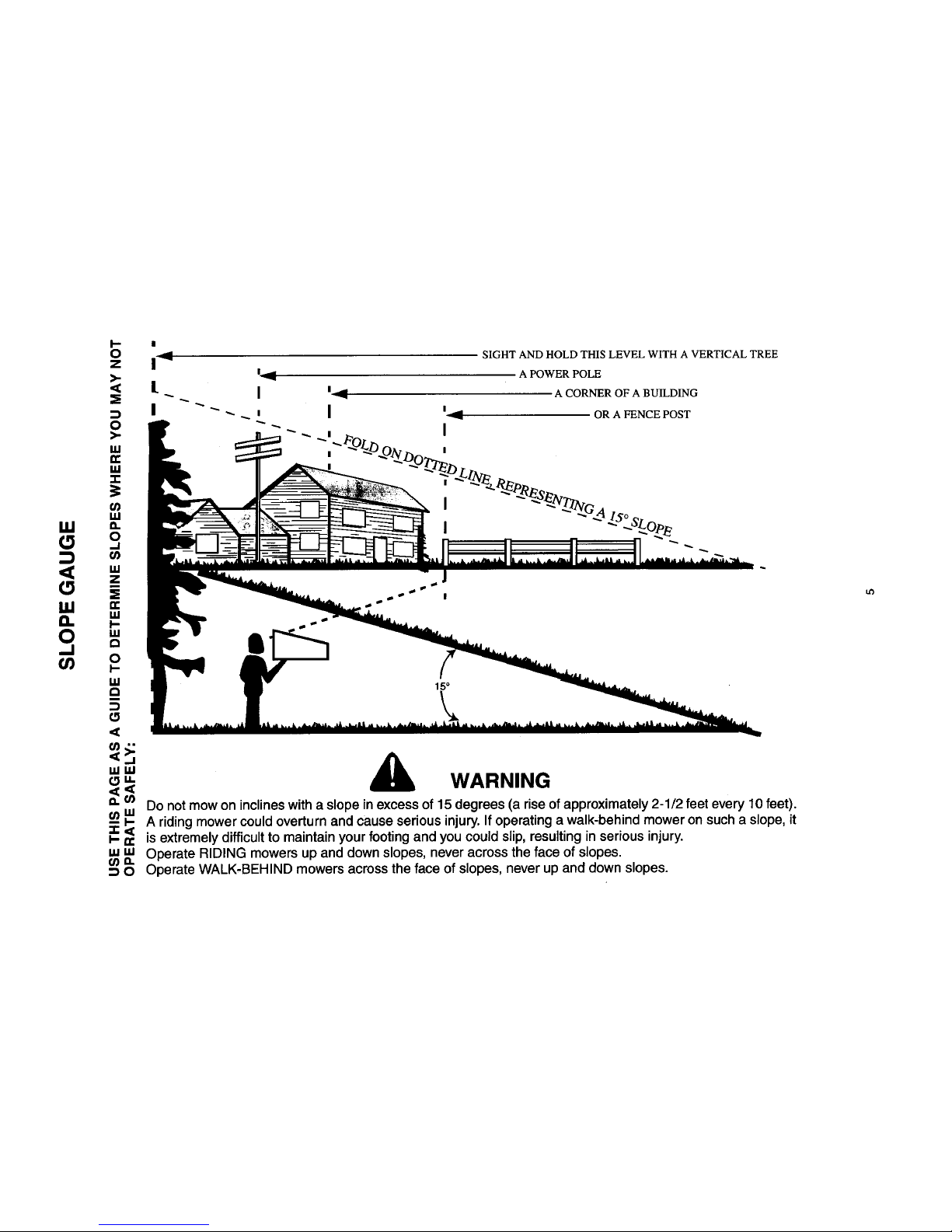
For your safety, use the slope gauge included as part ofthis
manual tomeasure slopes before operating thisunit on a
sloped or hilly area. If the slope is greater than 15 ° as shown
on the slope gauge, do not operate this unit inthat area or
serious injury could result.
Do:
Mow up and down slopes, not across.
Remove obstacles such as rocks, limbs, etc.
Watch for holes, ruts or bumps. Uneven terrain could
overturn the machine. Tall grass can hide obstacles.
Use slow speed. Choose a low enough gear sothat
you will not have to stop or shift while on the slope.
Always keep machine in gear when going down
slopes to take advantage of engine braking action.
Follow the manufacturer's recommendations for
wheel weights or counterweights toimprove stability.
3
Page 4
Use extra care with grass catchers or other
attachments. These can change the stability of the
machine.
Keep all movement on the slopes slow and gradual.
Do not make sudden changes in speed or direction.
Rapid engagement or braking could cause the front
of the machine to lift and rapidly flip over backwards
which could cause serious injury.
Avoid starting or stopping on a slope. If tires lose
traction, disengage the blade(s) and proceed slowly
straight down the slope.
Do Not:
Do not turn on slopes unless necessary; then, turn
slowlyand gradually downhill, ifpossible.
• Do not mow near drop-ells, ditches or
embankments.The mower could suddenly turn over
if a wheel is over the edge of a cliff orditch, or if an
edge caves in.
• Do not mow on wet grass. Reduced traction could
cause sliding.
Do not try to stabilize the machine by putting your
foot on the ground.
Do not use grass catcher on steep slopes.
Children
Tragic accidents can occur if the operator is not alert to the
presence of children, Children are often attracted to the
machine and the mowing activity. Never assume that
children will remain where you last saw them.
Keep children out of the mowing area and in
watchful care of an adult other than the operator,
Be alert and turn machine offifchildren enter the
area.
• Before and when backing, look behind and down for
small children.
• Never carry children. They may fall off and be
seriously injured or interfere with the safe machine
operation.
• Never allow children under 14 years old to operate
the machine. Children 14 years and over should only
operate machine under close parental supervision
and proper instruction,
• Use extra care when approaching blind comers,
shrubs, trees or other objects that may obscure your
vision of a child or other hazard.
• Remove key when machine is unattended to prevent
unauthorized operation.
Service
Use extreme care in handling gasoline and other
fuels. They are extremely flammable and the vapors
are explosive.
a. Use only an approved container.
a. Never remove fuel cap or add fuel with the
engine running. Allow engine to cool at least two
minutes before refueling.
b. Replace fuel cap securely and wipe off any
spilled fuel before starting the engine as it may
cause a fire or explosion.
c. Extinguish all cigarettes, cigars, pipes and other
sources of ignition.
d. Never refuel the machine indoors because fuel
vapors will accumulate in the area.
e. Never store the fuel container or machine inside
where there is an open flame or spark, such as a
gas hot water heater, space heater orfurnace.
Never run a machine inside a closed area.
To reduce fire hazard, keep the machine free of
grass, leaves or other debris build-up. Clean up oil or
fuel spillage. Allow machine to cool at least 5
minutes before storing.
Before cleaning, repairing or inspecting, make
certain the blade and all moving parts have stopped.
Disconnect the spark plug wire, and keep the wire
away from the spark plug to prevent accidental
starting.
Check the blade and engine mounting bolts at
frequent intervals for proper tightness. Also, visually
inspect blade for damage (e.g., excessive wear,
bent, cracked). Replace with blade which meets
odginal equipment specifications.
Keep all nuts, boltsand screws tight to be sure the
equipment is in safe working condition.
Never tamper with safety devices. Check their
proper operation regularly. Use all guards as
instructed in this manual.
After striking a foreign object, stop the engine,
remove the wire from the spark plug and thoroughly
inspect the mower for any damage. Repair the
damage before restarting and operating the mower.
Grass catcher components are subject to wear,
damage and deterioration, which could expose
moving parts or allow objects to be thrown, Foryour
safety protection, frequently check components and
replace with manufacturer's recommended parts
when necessary.
Mower blades are sharp end can cut. Wrap the
blade(s) or wear gloves and use extra caution when
servicing blade(s).
Check brake operation frequently. Adjust and
service as required,
Muffler, engine and belt guards become hot during
operation and can cause a bum. Allowto cool down
before touching.
DOnot change the engine governor settings or
overspeed the engine. Excessive engine speeds are
dangerous.
Observe proper disposal laws and regulations.
Improper disposal of fluids and matedals can harm
the environment and the ecology.
a. Prior to disposal, determine the proper method
to dispose of waste from your local office of
Environmental Protection Agency. Recycling
centers are established to properly dispose of
materials in an environmentally safe fashion,
b. Use proper containers when draining fluids. Do
notuse food or beverage containers that may
mislead someone into drinking from them.
Properly dispose of the containers immediately
following the draining of fluids.
c. DO NOT pour oil or other fluids into the ground,
down a drain or into a stream, pond, lake or
other body of water. Observe Environmental
Protection Agency regulations when disposing
of oil, fuel, coolant, brake fluid, filters, batteries,
tires and other harmful waste.
4
Page 5
SIGHT AND HOLD THIS LEVEL WITH A VERTICAL TREE
"'"' A
" WARNING
4<
a. U_ Do not mow on inclines with a slope in excess of 15 degrees (a rise of approximately 2-1/2 feet every 10 feet).
u_ _ A riding mower could overturn and cause serious injury. If operating a walk-behind mower on such a slope, it
_ is extremely difficult to maintain your footing and you could slip, resulting in serious injury.
"' "' Operate RIDING mowers up and down slopes, never across the face of slopes.
ma.
0 Operate WALK.BFHIND mowers across the face of slopes, never up and down slopes.
tO
Page 6

UNPACKING
Removing From Crate
• Remove all screws from bottom of the crate
using a 1/4" socket or a flat blade screwdriver.
• Holding the sides of the crate firmly, liftthe
crate up and keep itaside. Avoid tire
punctures.
• Remove and discard plasticbag which covers
the unit.
• Liftthe rear of the mower and clear the bottom
of the crate. Repeat for the front.
• Be sure parking brake is disengaged; roll unit
out of the crate's way.
Loose Pads
You willfind the following loose parts in the crate. To
identify these pads, see Figure 1. Remove loose
parts very carefully so as not to damage or lose any.
1. Steering wheel components: steering wheel, cap,
shaft, tube
2. Operator's manual (not shown in Figure 1)
3. Mulching plug & side-discharge chute
4. Oil drain sleeve
5. Battery acid pack* (not shown in Figure 1)
6. Battery cover
7. Ignition keys (not shown in Figure 1)
8. Steering gear cover
9. Bumper (optional)
10. Hitch Plate (optional)
* Notincludedasloosepartifunitshipped withwetbattery
Side-Discharge Chute
Mulching
Plug
Seat
Steering
Shaft
Steering
Wheel
rein
Sleeve
Steering
Wheel
Cap
Steering
Tube
J
Hitch Plate
(Optional) Bumper
_;_ _onal)
Figure 1
Steering
Gear Cover
Page 7
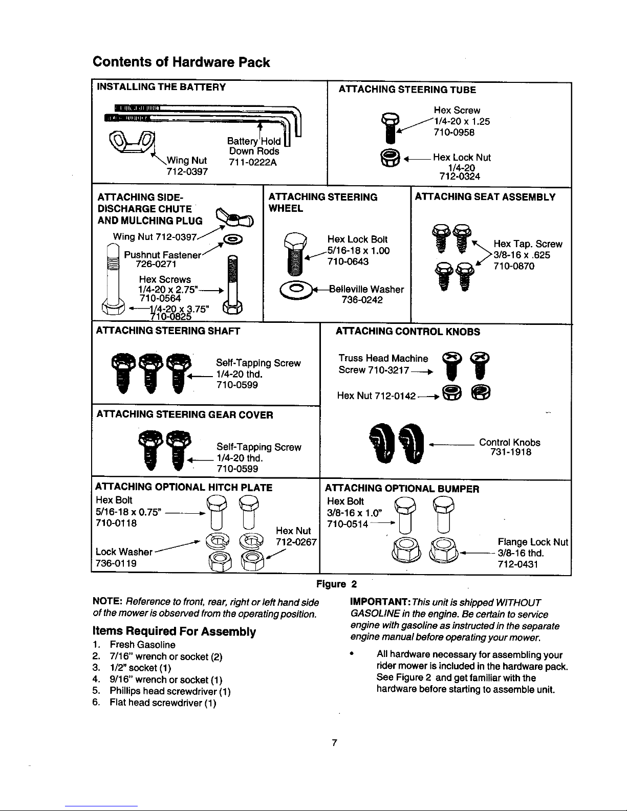
Contents of Hardware Pack
INSTALLING THE BATTERY
llllL_IIlmulll] I
Batte Id
Down Rods
Wing Nut 711-0222A
712-0397
ATTACHING STEERING TUBE
Hex Screw
125
710-0958
_}<_ Hex Lock Nut
1/4-20
712-0324
ATTACHING SIDE-
DISCHARGE CHUTE
AND MULCHING PLUG
,Wing Nut 712-0397/,-_
Pushnut Fastener / --
__ 726-0271
Hex Screws
1/4-20 x 2.75"---_
710-0564
__) "-_1/4-20 x 3.75" (_
710-0825
ATTACHING STEERING SHAFT
ATTACHING STEERING
WHEEL
se,,.Tapp,nosorew
_'<.---_ 1/4-20 thd.
710-0599
ATTACHING STEERING GEAR COVER
,;.1,Se,,-,'. , in0 crow
1/4-20 thd.
710-0599
ATTACHING OPTIONAL HITCH PLATE
Hex Bolt _
5/16-18 x 0.75"
710-0118
Hsx Nut
LockWasher/ .y2-0287
736-0119 ,, , ,
Hex Lock Bolt
"11 4,,-f5/16"18 x 1.00
Ij 710-0643
(_Belleville Washer
736-0242
NOTE: Reference to front, rear, right or left hand side
of the mower is observed from the operating position.
ATTACHING SEAT ASSEMBLY
_ _r,,,_ Hex Tap. Screw
ATTACHING CONTROL KNOBS
Truss Head Machine _;)
Screw 710-3217----_
Hex Nut 712-0142 _ _
Control Knobs
731-1918
ATTACHING OPTIONAL BUMPER
HexBolt _ _
3/8-16 x 1.0"
710-0514 ---_"
_ Flange Lock Nut
_'_'------_ 3/8-16 thd.
712-0431
Figure 2
Items Required For Assembly
1. Fresh Gasoline
2. 7/16" wrench orsocket (2)
3. 1/2"socket (1)
4. 9/16" wrench or socket (1)
5. Phillips head screwdriver (1)
6. Flat head screwdriver (1)
IMPORTANT: This unit isshipped WITHOUT
GASOLINE in the engine. Be certain to service
engine with gasoline as instructed in the separate
engine manual before operating your mower.
All hardware necessary for assembling your
rider mower is included in the hardware pack.
See Figure 2 and get familiar with the
hardware before starting to assemble unit.
7
Page 8
ASSEMBLY
Installing Battery
A
WARNING: Battery acid must be handled
with great care as contact with it can burn
and blister the skin. Wear protective
clothing (goggles, rubber gloves and apron)
when working with it.
Always shield eyes, protect skin and
clothing when working near batteries.
Always keep battery out of reach of
children.
Should battery acid accidentally splatter
into the eyes or ontothe face, rinse the
affected area immediately with clean cold
water. Ifthere is any further discomfort,
seek prompt medical attention.
If acid spills on clothing, first dilute it with
clean water, then neutralize with a solution
of ammonia/water or baking soda/water.
Since battery acid Is corrosive, do not
pour it into any sink or drain. Before
discarding empty electrolyte containers,
rinse them with a neutralizing solution.
Never connect or disconnect charger clips
to battery while charger isturned on as it
can cause sparks.
Keep all lighted materials (cigarettes,
matches, lighters) away from the battery as
the hydrogen gas generated during
charging can be combustible.
As a further precaution, only charge the
battery in a well-ventilated area. Make
certain venting path of battery (drain tube) is
always open.
Antidote
External: Flush with water.
Internal: Drink large quantities of water or
milk. Follow with milk of magnesia, beaten
eggs or vegetable oil. Seek medical help
immediately.
Eyes: Flush with cool water for at least 15
minutes, then get prompt medical attention.
Activating the Battery
IMPORTANT: If your rider mower was shipped witha
wet battery, that is with the battery already filled with
electrolyte, skip the battery set-up section entirely
and go to "installing the Battery"section on page 9.
NOTE: Continue assembling the rider mower while
thebattery is standing for30 minutes (after fillingwith
acid), and later whileyou are charging the battery.
Follow the safety precautions mentioned previously.
Also remember to take added precaution, as stated
below, while activating the battery.
WARNING: When not in use, keep the
terminal covers in place.
Do not short battery terminals (avoid a
connection between the two battery posts
or between the positive terminal and the
frame of the ridingmower),
Before installing battery, remove metal
bracelets, wristwatch bands, rings,etc.
from your person.
Connect positive terminal first to prevent
sparks from accidental grounding.
Do not use the rider mower battery to start
other vehicles.
Carefully remove electrolyte (battery fluid, acid)
pack from its box.
Using a flat head screwdriver, remove the cell
caps from the battery.
Open the carton containing the electrolyte
(acid) pack pouch. Cut 1/4" from the spouton
top of the acid pack.
Fill each cell of the battery up to the split ring.
Do not exceed the maximum fill level.
Allow the battery to stand for 30 minutes with
the caps off. The electrolyte level may drop due
tothe chemical reaction inthe battery. Add if
necessary.
Do not overfill the battery. Overfilling the battery
can cause leakage which can damage your
new rider mower.
Replace the cell caps on the battery.
Charging the Battery
WARNING: While charging the battery, do
not smoke. Keep the battery away from
any sparks. The fumes from the battery acid
can cause an explosion.
After the battery has been charged, add
only distilled water. Do not add acid.
After fillingwith acid the battery has reached
85% charging capacity. A newly activated
battery will reach 100% capacity in 1 to 2.5
hours with a 3 ampere charge.
Page 9

Abattery charged by the alternator willhave
the same life as a battery bench charged prior
to installationprovided that the engine isrun for
1 to 2.5 hourswith a 3 ampere alternator for the
initialcharge.
NOTE: After battery has been charged, add only
distilled water. Do not add electrolyte (battery fluid,
acid).
Disposing of electrolyte
After tilling the cells tothe proper level, you may have
some extra electrolyte (battery fluid, acid) left over.
Followthe steps below for properdisposal.
• Fill the plastic container halfway with tap water.
Put two tablespoons of baking soda in the
electrolyte/water mix. Fill rest ofthe container
with water.
• Pour the baking soda, water and electrolyte
mixdown the sink drain under runningwater.
* Throw the plastic container inthe garbage.
NOTE: The information listed above is for initial
charge. Refer to the Maintenance section of this
manual forbattery care and charging instructions
after regular usage.
Installing the battery
• Pivot the cover of the mower upwards as
shown in Figure 3.
through the hole in the battery tray.
Pull up on the hold-down rodsthrough the
on the battery cover and insert one wing m
each hold-down rod. Tighten the two wing
to secure the battery to the unit.See Figur_
Wing Nu
Figure 4
Attaching Steering Tube
• Slide the steering tube intothe steedng su
bracket assembly.
• Secure with hex screw and hex inserted Io
nut from the hardware pack. See Figure 5.
Steering Tube.--,.
Steering Support
Bracket-Assembly
Installbattery
here
Hex Screw
Figure 3
Place the battery intothe battery opening with
positive terminal toward the rear of the unit.
Make certain both the negative (black) cable
and the positive (red) cable are routed up
through the battery opening. See Figure 4.
Attach the positive (red) cable to the positive
terminal of the battery. See Figure 4. Secure
with hax bolt and nut provided with the battery.
Slide rubber boot over the positiveterminal.
Attachnegative cableto the negative terminalwith
a hex boltandnut provided.See Figure4.
Hook the curved end of the hold-down rod
Flgure 5
Attaching Steering Gear Cover, Optio
Bumper & Optional Hitch Plate
• Align the two holes on the steering gear c(
with the two corresponding holes on the fr
frame of the rider.See Figure 6A,
• Insert two self-tapping screws from the
hardware pack through these two holes ot
gear cover and the frame as shown in Fig_
6A. Secure tightly.
• If your rider mower is equipped with the
optional Bumper, align the two holes at h
ends of the tube with the corresponding hc
on the front of the rider. See Figure 6B. In_
the two hex bolts from hardware pack as st
and secure with the lock nut.
9
Page 10
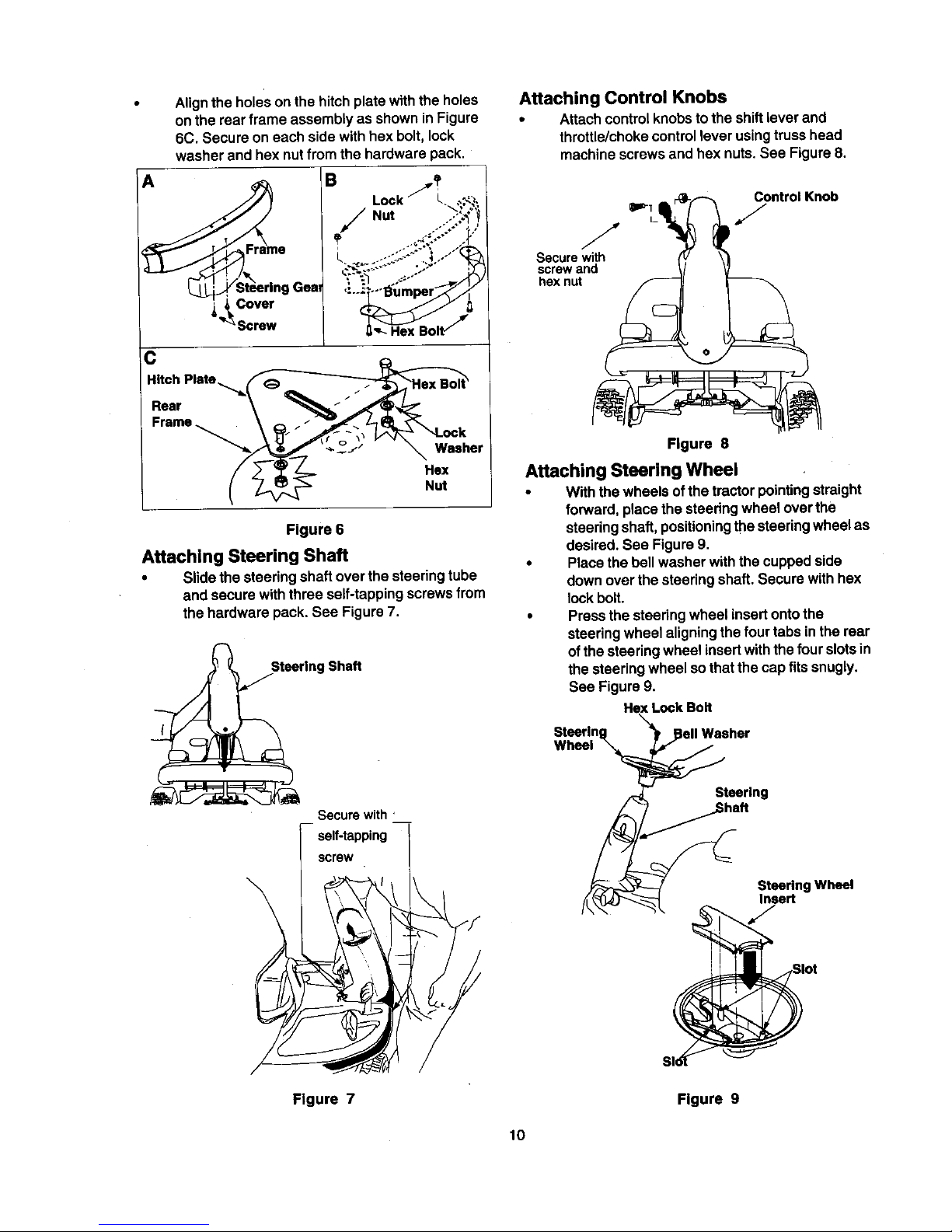
Aligntheholes on the hitch plate with the holes
on the rear frame assembly as shown in Figure
6C. Secure on each side with hex bolt, lock
washer and hex nut from the hardware pack.
rame
Coven"
"_ Screw
B
Lock L ,.._,
Gea ,:.._
:C
Hitch Plate ._._(
Rear
Frame _
_1_ /// /
_ _t ¢ _ °Cker
' 3: _- Hex
Figure 6
Attaching Steering Shaft
• Slide the steering shaft over the steering tube
and secure with three self-tapping screws from
the hardware pack. See Figure 7.
_Steerlng Shaft
Securewith '
_ self-tapping
screw
Attaching Control Knobs
• Attach control knobs to the shift lever and
throttle/choke control lever using truss head
machine screws and hex nuts. See Figure 8.
0==-1- _ _ Control Knob
Figure 8
Attaching Steering Wheel
• With the wheels of the tractor pointing straight
forward, place the steering wheel over the
steering shaft, positioning the steering wheel as
desired. See Figure 9.
• Place the bell washer with the cupped side
down over the steering shaft. Secure with hex
lock bolt.
• Press the steering wheel insertonto the
steering wheel aligning the four tabs in the rear
of the steering wheel insertwith the four slotsin
the steering wheel so that the cap fits snugly.
See Figure 9.
He](Lock Bolt
Steering _sher
Wheel
Steering
..._.i Shaft
Steering Wheel
Insert
J
Figure 7 Figure 9
10
Page 11
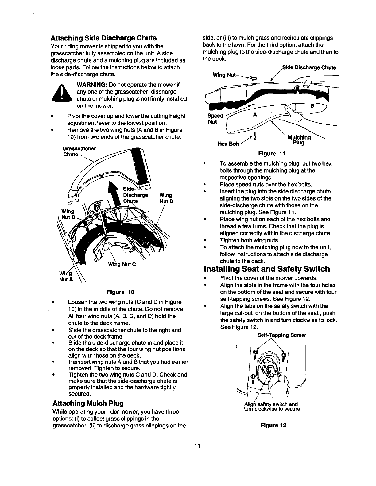
Attaching Side Discharge Chute
Your riding mower isshipped to you with the
gresscatcher fullyassembled on the unit. A side
discharge chute and a mulching plug are included as
loose parts. Follow the instructionsbelow to attach
the side-discharge chute.
WARNING: Do not operate the mower if
any one of the grasscatcher, discharge
chute or mulching plug isnotfirmly installed
on the mower.
Pivot the cover upand lower the cutting height
adjustment lever tothe lowest position.
Remove the two wing nuts (A and B in Figure
10) from two ends of the grasscatcher chute.
Grasscatcher
Wing
Discharge Wing
Nut B
Nut C
Nut A
Figure 10
Loosen the two wing nuts (C and D in Figure
10) in the middleof the chute. Do not remove.
Allfour wing nuts (A, B, C, and D) hold the
chute to the deck frame.
Slide the grasscatcher chute to the rightand
out of the deck frame.
Slide the side-discharge chute inand place it
on the deck sothat the four wing nut positions
align with those on the deck.
Reinsert wing nuts A and Bthat you had earlier
removed. Tighten to secure.
Tighten the two wing nuts C and D. Check and
make sure that the side-discharge chute is
properly installed and the hardware tightly
secured.
Attaching Mulch Plug
While operating your rider mower, you have three
options: (i) to collect grass clippings inthe
grasscatcher, (ii) to discharge grass clippings on the
side, or (iii) to mulch grass and recirculate clippings
back to the lawn. For the third option, attach the
mulching plug tothe side-discharge chute and then to
the deck.
Wing Nut_ FSlde Discharge Chute
Speed-
Nut
Mulching
Plug
Figure 11
• To assemble the mulching plug, puttwo hex
boltsthrough the mulching plug at the
respective openings.
• Place speed nuts over the hex bolts.
• insert the plug intothe side discharge chute
aligning the two slots on the two sides ofthe
side-discharge chute with those on the
mulching plug. See Figure 11.
• Place wing nut on each of the hex bolts and
thread a few turns. Check that the plug is
aligned correctly within the discharge chute.
• Tighten both wing nuts
• To attach the mulching plug now to the unit,
follow instructionsto attach side discharge
chute to the deck.
Installing Seat and Safety Switch
• Pivot the cover of the mower upwards.
• Align the slots inthe frame with the four holes
on the bottom of the seat and secure with four
self-tapping screws. See Figure 12.
• Align the tabs on the safety switch with the
large cut-out onthe bottom of the seat, push
the safety switch in and turn clockwise to lock.
See Figure 12.
Se_plng Screw
Aligt
turn
safetyswitchand
:lock'wisetosecure
Figure 12
11
Page 12
OPERATION
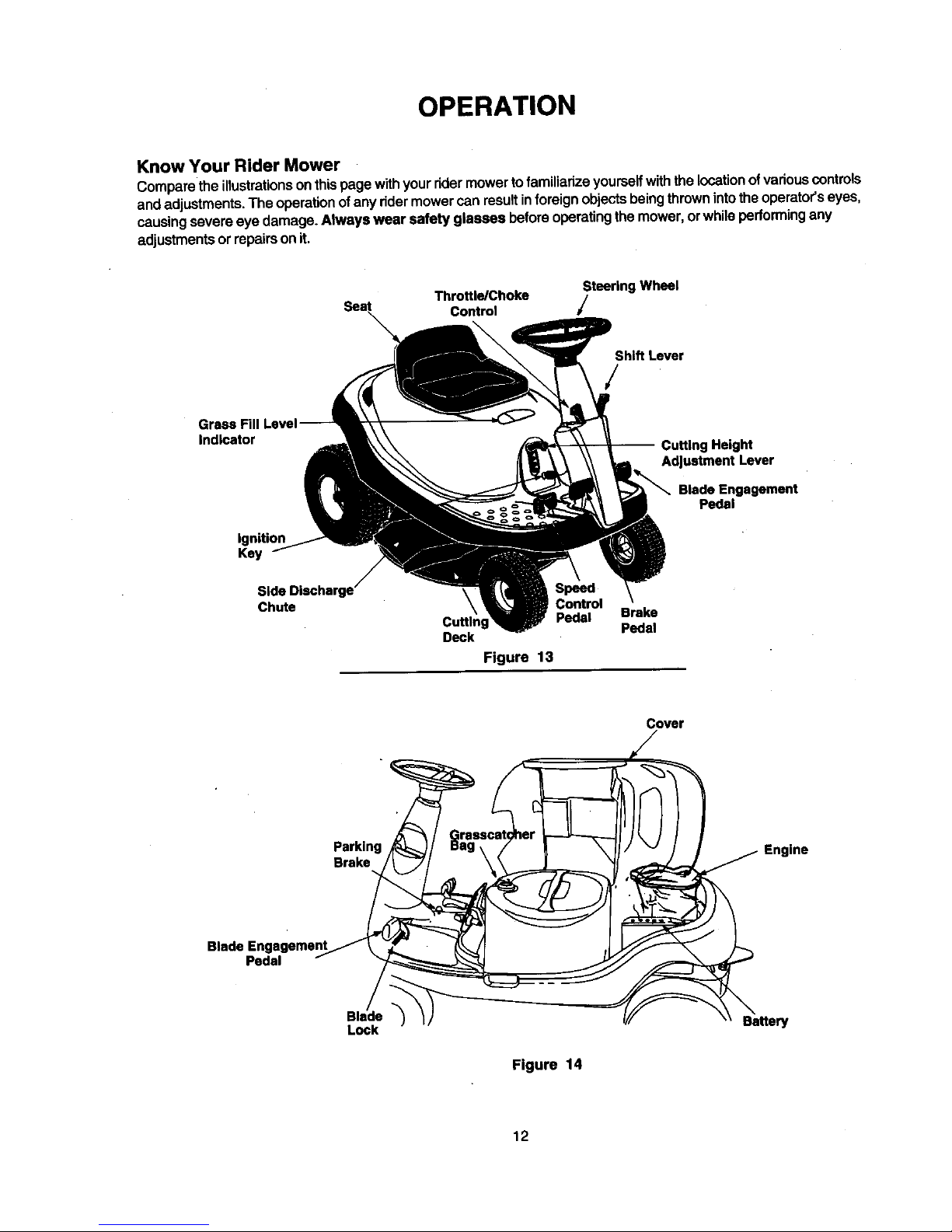
Know Your Rider Mower
Compare the illustrationsonthis page withyour rider mower to familiarizeyourself withthe location ofvarious controls
and adjustments. The operation of any rider mower can result in foreign objects being thrown into the operator's eyes,
causing severe eye damage. Always wear safety glasses before operating the mower, or while performing any
adjustments or repairs on it.
Throttle/Choke Steering Wheel
Control J
Shift Lever
GrsssFill
Indicator
g Height
Adjustment Lever
Blade Engagement
Pedal
Key
Side Discharge
Chute
\ SpeedControl
Cutting Pedal Brake
Pedal
Deck
Figure 13
Cover
Brake
Engine
Pedal
Lock
Figure 14
Battery
12
Page 13
Know the Controls
(Refer to Figure 13 and Figure 14.)
Throttle/Choke Control: Use to regulate the engine
speed and to start the engine.
Speed Control Pedal: Use to regulate the ground
speed of the rider mower.
Ignition Switch: Use to turn the engine ON or OFF.
Shift Lever: Use to change direction of the mower.
Grass Fill Level Indicator: Use to determine the
level of grass clipping inthe bag and when to stop
and empty it.
Parking Brake:Use tostop the mower from moving
while parked.
Blade Engagement Pedal: Use to engage or
disengage the blade.
Blade Lock: Use to lock blade at the engaged
position.
Cutting Height Adjustment Lever: Use to raise and
lower the cuttingdeck which determines the cutting
height.
Brake Pedal: Use to stop the mower's forward or
reverse motion.
Safety Interlock
This unit is equipped with a safety interlocksystem for
your protection. The interlock safety switches are
connected to the brake pedal, the blade engagement
pedal, the shift lever, and the seat.
The purpose ofthe safety interlocksystem is
threefold:
a to prevent the engine from starting unless
the brake pedal is depressed and the blade
engagement pedal isdisengaged;
b. to shut off the engine if the blade pedal is
not disengaged when the shift lever is put
intoreverse; and
c. to shut the engine off when the operator
leaves the seat without engaging the
parking brake.
,_ WARNING: To avoid the dsk of serious
injury,do not operate the rider mower if the
interlock system is malfunctioning,
To Maintain Safety
WARNING: It is very important that you
maintain safety while operating your rider
mower. Observing the caution rules
mentioned below will enable you to enjoy
your rider mower.
Avoid serious injury or death.
Go up and down slopes, not across.
Avoid sudden turns.
Do not operate the unitwhere itcould slipor tip.
Ifyour rider mower stops while going uphill,
stop the blade(s) and reverse downhillslowly.
Do not mow when children or others are
around. Never carry children.
Lookdown and behind before and while
reversing.
Keep safety devices (guards, shields, and
switches) in place and working.
Remove objects that could be thrown by the
blade(s).
Know locationand function of all controls.
Be sure blade(s) and engine are stopped
before placing hands or feet near blade(s).
Before leaving operator's position,disengage
blade(s), place the shiftlever in neutral, engage
parkingbrake, shut engine off and remove key.
Stopping Mower
• Release blade engagement pedal all the way.
• Release the speed control pedal and depress
the brake pedal.
• When the mower comes to a complete stop,
place the shift lever in neutral.
• Engage the parking brake by pulling up on the
parking brake knob.
• Turn the ignitionkey to OFF position and
remove the key.
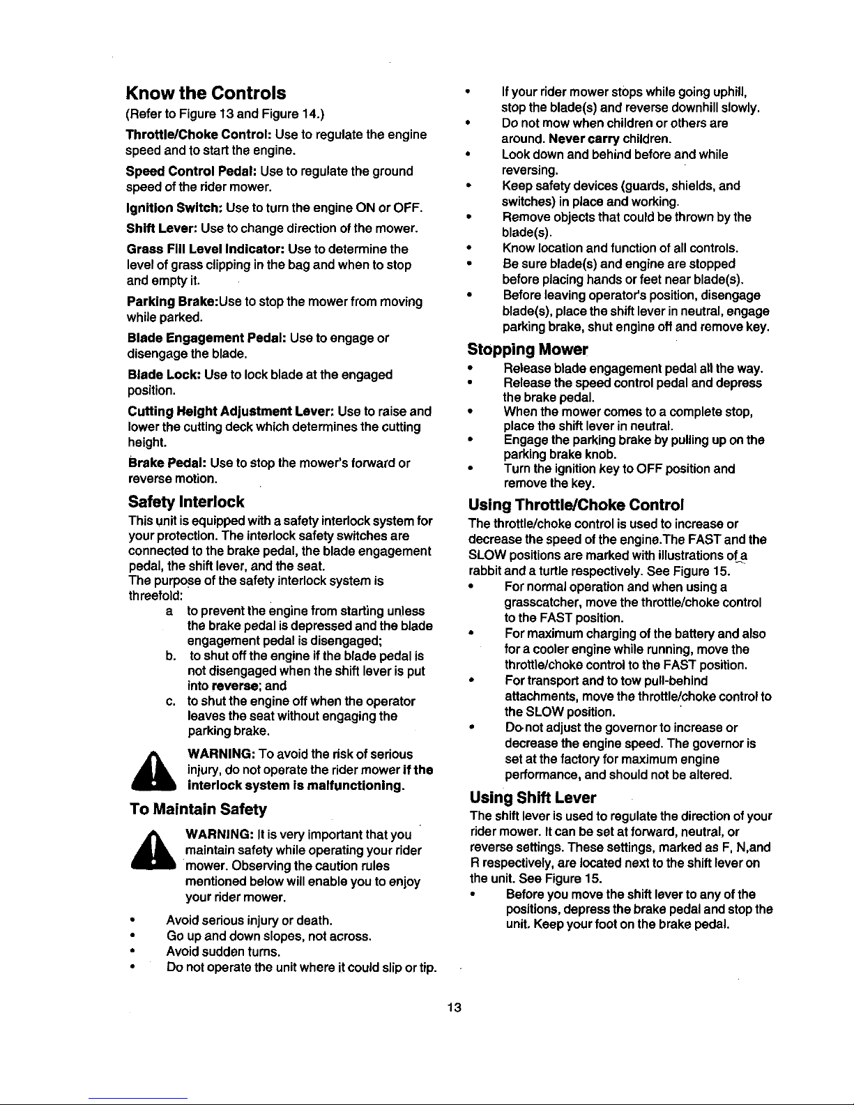
Using Throttle/Choke Control
The throttle/choke control is used to increase or
decrease the speed of the engine.The FAST and the
SLOW positionsare marked with illustrationsof a
rabbitand a turtle respectively. See Figure 15.
• For normal operation and when using a
grasscatcher, move the throttle/choke control
tothe FAST position.
• For maximum charging of the battery and also
for a cooler engine while running, move the
throttle/choke controlto the FAST position.
• For transport and to tow pull-behind
attachments, move the throttle/choke controlto
the SLOW position.
• Do.not adjust the governor to increase or
decrease the engine speed. The governor is
set at the factory for maximum engine
performance, and should not be altered.
Using Shift Lever
The shift lever isused to regulate the direction of your
rider mower. Itcan be set at forward, neutral, or
reverse settings.These settings, marked as F, N,and
R respectively, are located next tothe shift lever on
the unit.See Figure 15.
• Before you move the shift lever toany of the
positions,depress the brake pedal and stopthe
unit, Keep your foot on the brake pedal.
13
Page 14
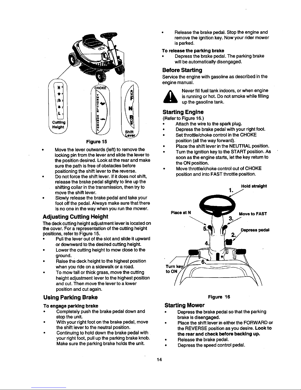
Figure 15
Move the lever outwards (left) to remove the
locking pinfrom the lever and slide the lever to
the positiondesired. Lookat the rear and make
sure the path isfree of obstacles before
positioningthe shift lever to the reverse.
Do not force the shiftlever. If it does not shift,
release the brake pedal slightly to line up the
shiftingcollar in the transmission, then try to
move the shift lever.
Slowly release the brake pedal and take your
foot off the pedal. Always make sure that there
isno one in the way when you runthe mower.
Adjusting Cutting Height
The deck cutting height adjustment lever is located on
the cover. For a representation of the cutting height
positions, refer to Figure 15.
• Pull the lever out of the slot and slide it upward
or downward to the desired cutting height.
• Lower the cutting height to mow close tothe
ground.
• Raise the deck height to the highest position
when you ride on a sidewalk or a road.
• To mow tall or thick grass, move the cutting
height adjustment lever to the highest position
and cut. Then move the lever to a lower
position and cut again.
Using Parking Brake
To engage parking brake
• Completely push the brake pedal down and
stop the unit.
• With your right foot on the brake pedal, move
the shift lever to the neutral position.
• Continuing to hold down the brake pedal with
your right foot, pull up the parking brake knob.
Make sure the parking brake holds the unit.
Release the brake pedal. Stop the engine and
remove the ignitionkey. Now your rider mower
isparked.
To release the parking brake
• Depress the brake pedal. The parking brake
willbe automatically disengaged.
Before Starting
Service the engine with gasoline as described inthe
engine manual.
Never fill fuel tank indoors, or when engine
isrunningor hot. Do not smoke whilefilling
up the gasoline tank.
Starting Engine
(Refer to Figure 16.)
• Attach the wire to the spark plug.
• Depress the brake pedal with your fight foot.
• Set throttle/choke controlin the CHOKE
position (all the way fonNard).
• Place the shift lever in the NEUTRAL position.
• Turn the ignition key to the START position. As
soon as the engine starts, letthe key return to
the ON position.
• Move throttle/choke controlout of CHOKE
positionand intoFAST throttle position.
Hold straight
1.
Placeat N Move to FAST
2J
toON
Figure 16
Starting Mower
• Depress the brake pedal so that the parking
brake is disengaged.
• Place the shiftlever ineither the FORWARD or
the REVERSE position as you desire. Look to
the rear and check before backing up,
• Release the brake pedal.
• Depress the speed controlpedal.
14
Page 15

• To stop, release the speed control pedal and
depress the brake pedal.
• Press the blade engagement pedal downward
until the blades are turning.The blades can be
engaged either while the mower is in motion or
while it is standing.
Your rider mower is equipped with a blade lock to
keep the blade engaged without the operator having
to depress the blade pedal continuously.
• To engage the blade lock: While pressing
down on the blade pedal, push the blade lock
down with your heel. It should click into the
"blade engaged" position.To disengage the
blade lock, simply push down on the blade
pedal and release the lock.
WARNING: When the blades are engaged,
keep feet and hands away from the
discharge opening, the blades or any part
of the deck.
Stopping Mower
• Release blade engagement pedal all the way.
• Release the speed controlpedal and depress
the brake pedal.
• When the mower comes to a complete stop,
place the shift lever in neutral.
• Engage the parking brake by pulling up on the
parking brake knob.
• Turn the ignitionkey to OFF position and
remove the key.
NOTE: Do not leave the key inthe ON position when
you are not operating the mower. Such action will
drain the battery dead.
Grass Fill Level Indicator
This indicator was designed to add convenience to
your ridingmower. While the mower isrunning, air will
flow through the discharge chute and intothe grass
catcher. If the grass catcher is empty, air flows
through easily pushing the ball up. Ifthe grass
catcher is full, airdoes not flow through itallowing the
ball tofall. So ifyou see the white ball in the
grasscatcher fill level indicator falling down, you
should stop the mower and empty the bag.
To Empty Grasscatcher
• Stop the mower completely, pull up on the
parking brake knob and take the ignition key
out. Get offthe operator's seat.
• Pivot the cover up. Pull up the grasscatcher
bag bythe handle and take it to the proper
disposal site. See Figure 17.
• Hold the bag away from your body. Push
down on the bag lever and let the bottom
section of the bag fall downwards. The grass
clippings will be disposed of from the
bottom.See Figure 17.
Tap the bag on the ground so that the three
legs of the bag press against the ground. The
bag lever should snap close while you pushthe
bag downwards.
Replace the bag on to the mower making sure
the bag isplaced on the flange on top of the
discharge chute. Pivot the cover down.
_rasscatcher
ag
Handle
PU_eUS hre
Figure 17
Using The Mower
Observe the safety rules listedon pages 3-5 and 13 of
this manual for safe operation of your mower.
• Before mowing,make surethatthe cuffingdeck is
leveled. For deck adjustment,referto page 20.
• You can engage the blade by pressing on the
blade engagement pedal with your left foot
while sittingon the operator's seat.
• When mowing an area for the first time, watch
out for objects lying on the grass. Ifyou strike a
foreign object, stop the engine. Remove wire
from spark plug and thoroughly inspectthe
mower for any damage. Repair the damage
before operating itagain.
• Avoid scalping the lawn by adjusting the cutting
height upwards and/or sharpening the blades.
• Mow at fullthrottle. Learn the terrain on which
you are mowing. For best mowing results, mow
only when the grass is dry.
15
Page 16

The recommended mowing pattem isgiven
below:
Mow grass often and in regular intervals so that
you can cut only 1/3 of the grass blade in one
mowing.
To empty grass bag, stop the mowe r
completely, engage the parking brake, and
turn the ignition off. This willprevent the hot
engine exhaust gas from browning the grass.
• Many communities no longer haul grass
clippings to landfills. Composting the clippings
from your grasscatcher isa viable solution. For
this you witt have to empty the grasscatcher at
the designated composting site.
• Your ddermower is equipped witha mulching
plugto mulchthe grass and recycleintothe lawn
insteadofcollectingin the grasscatcherbag.
• Mulch only when the grass is dry. Mulchingwet
grass may damage the underside of the deck
because wet grass tends tostick to it. Clean
deck thoroughly ifyou mulch wet grass.
• For effective mulching, overlap mowing paths
so that the c{ipplngsare distributed evenly.
SERVICE & ADJUSTMENTS
WARNING: Do not at any time make any
adjustment to ridingmower without first
stopping engine and disconnecting
spark plug wire.
Brake Pedal Adjustment
During normal operation of the rider mower, the brake
is subject to wear and tear. Check the brake
periodically by carrying out the following test:
• Release the parking brake and place the rider
mower in neutral. Depress the brake pedal and
tryto rollthe ridermower. The tractor should not
move. Ifthe tractor moves, adjust the brake.
WARNING: Do not adjust thebrake while the
engine Is running. Besure to block the
wheels ofthe ridermower before making any
adjustments on thebrake cable.
Adjustment to the brake pedal is made at the cable
end. See Figure 18,
• Set the parking brake and turn ignitionkey off.
• Shift the cutting height lever to the lowest
position.
• Pivot the cover up and remove the
grasscatcher bag and the side-discharge
chute or the mulchingplug from the mower.
• Disconnect wire from the spark plug.
• Locate the brake cable on the right side under
the front housing.
= Using a pairof 1/2" wrenches, loosen the jam
nuts and back the cable out to tighten or
thread inward to loosen.
• Retighten the jam nutswhen propertension is
reached.
• Unlock the parking brake and repeat the test
described above. Readjust if necessary. -
Brake
Cable
Lock Washer
Cable* -j
Loosen ==_===11===_
•s.mo ooo,a iu°,mo°,anbo,.cob,a.
<,n'yan;,ho*nho.
Figure 18
16
Page 17

Speed Control Pedal Adjustment
Adjustment to the speed control pedal is made at the
cable end. See Figure 18.
• Set the parking brake and turn ignition key off.
• Shift the cutting height lever tothe lowest
position.
• Pivot the cover up and remove the
grasscatcher bag and the side-discharge chute
or the mulching plug from the mower.
• Disconnect wire from the spark plug.
• Locate the speed control cable under the front
housing.
• Loosen the jam nuts and back the cable outto
tighten or thread inward to loosen.
• Retighten the jam nuts when proper tension is
reached.
• Reconnect the spark plug wire and pivot the
cover down.
Seat Adjustment
The seat position on the rider mower can be adjusted
to maximize the operator's convenience.
• Stop the mower completely and engage the
parking brake. Turn ignitionoff.
• Pivot the cover up.
• Loosen the four self-tapping screws on the
bottomof the seat.
• Slide the seat forward or backward in the slot,
and position it as desired.
• Retighten the four screws.
Wheel Alignment
The frontwheels should toe-in 1/16-5/16 inch. To
adjusttoe-in, follow these steps:
• Remove the 3/8" hex nut which holds the ball
joint to the steering segment. See Figure 19.
• Adjust the ball joint in or out untilthe wheels
toe-in approximately 1/16-5/16" (Dimension
"B" should be approximately 1/16-5/16" less
than dimension "A"). See Figure 19.
• Replace the balljoint intothe steering segment,
and replace the 3/8" hex nut.
Blade Brake/PTO Adjustment
The blade engagement pedal should be adjusted
so that if you depress it about 3/4" from the front of
the slot, it should start engaging the deck belt. The
PTO (power take off) switch is located in the blade
brake slot on the left side of the upper frame. See
Figure 20. The brake engagement pedal needs to
make contact with the PTO switch for the engine to
start.
Under normal operation, the blade engagement pedal
should not require frequent adjustment. However,
perform the following test periodically and make sure
that itis infine working condition.
• Pivot the cover up and check ifthere isenough
slack on the deck engagement cable.
• Depress the blade engagement pedal (about
3/4 inch) and check if the belt is engaging.
• If the cable is tightor too loose or the belt isnot
engaging, adjust the deck engagement cable.
Hex Nut
Steering Segment
Ball Joint
Tie Rod
A.
_- front
B.
(1/16-5/16" less than A)
Figure 19
_v
17
Page 18

NOTE: You willhave reached correct adjustment to
the deck engagement cable when the cable moves
approximately 1/2" offcenter fine in both directions.
Adjustment to the blade brake willhave to be made at
the cable end. See Figure 20.
Deck _\\ Hex
Engagement_ _ \ \\ Nut
IBpleeddelEngagement_ 1
s
Pedodically check tosee ifthese belts are too
loose or damaged through wear and tear. If so,
replace with new belt. While ordering these
belts, refer tothe Parts Listsection in this
manual for the correct part number.
Deck Belt
Engage the parking brake and turn the ignition
off. Pivot the cover up and remove the
grasscatcher. Remove the spark plug wire.
Put the deck at the lowest cuttingheight by
adjusting the cutting height adjustment lever to
the lowest position.
Working from the rear ofthe mower, remove
the hex nut and the lock washer on the right
side ofthe deck belt guard. You willneed a
7/16" socket wrench with 6" extension to
remove this bolt.
Remove
sett-tapping
screw
Remove hex nut &
lock washer
Figure 20
Ifthe belt isslipping when you depress the
blade engagement pedal about 3/4", loosen the
two hex nuts on the cable. See Figure 20.
If the belt isengaging sooner than when the
blade engagement pedal is 3/4" from the PTO
switch, tighten both the hax nutson the cable.
See Figure 20.
Repeat the blade engagement test and
readjust if necessary.
Pivot the cover back to itsOriginalposition.
Belt Replacement
There are two drive belts and one deck belt inyour
rider mower; follow the description below to identify
the belts.
1. The lower drive belt goes from the variable speed
pulley to the transmission pulley.
2. The upper drive belt goes from the variable
speed pulley to the upper sheave of engine
pulley.
3. The deck belt goes from the deck pulley to the
lower sheave in engine pulley.
(Viewfromunderneaththemowerwhile
workingfrom the rear)
Figure 21
Using a 3/8" socket wrench, remove the self-
tapping screw that holds opposite side of the
deck belt guard. See Figure 21. Push the right
side ofthe deck belt guard forward and let it
drop down.
Using a 1/2" socket wrench, remove two self-
tappingscrews,lockwasher and hexnutthat hold
the deck belt cover to the deck. See Figure22.
Forthis,you willhave to workfrom the topleft
side of the mower. Remove thebelt cover.
Using a 9/16" wrench, loosen the hex nuton the
idler pulley. See Figure 22.
Remove belt from around deck pulley, idler
pulley, and the engine pulley.
Place the new belt around the deck pulley and
the engine pulley making sure that the belt is
routed inside the belt keepers. There are two
18
Page 19

belt keepers under the grasscatcher, one on
the idler and the other under the deck belt
cover. See Figure 22.
Reinstall the deck belt cover and secure with
the two self-tapping screws and the lock
washer and hex nut.
NOTE: Belt keeper ".4"must be mounted on the
outside of the belt.
Imaginary
Belt Line Belt
Keeper Keeper "A"
Deck Belt
Cover_
the same locationfrom where itwas removed.
Upper Variable Speed Belt
• Remove the engine pulley using a 9/16" socket
wrench with a 6"extension. The engine pulley
is located in front of the transmission.
• Drop the engine pulley down and remove the
belt from around it.
• Push the idler bracket to the right and remove
the belt. See Figure 23.
• Replace belt and reassemble in reverse order.
Transmission Variable Speed Pulley
Spring
Spring Loaded
Loaded Idler
Idler
_ Engine
Pulley
Self-Tapping
Screw
Pulley
Figure 22
Make sure to align the belt keeper in line with
the frame. See Figure 22. NOTE: Animaginary
line between the belt keeper and idler pulley
should be parallel to frame as shown above.
Again working from under the rear of the
mower, reinstall the rear deck belt guard.
Replace the grasecatcher and pivot the cover
back.
Lower Variable Speed Belt
• Remove the rear deck belt guard following first
five steps for deck belt removal on page 17.
Remove belt from the engine pulley.
• Push the spring loaded idler, located on the left
side of the transmission, to the right. Remove
belt from around the idler and then the
transmission pulley. See Figure 23.
• Using a 9/16" socket, remove bolt, spacer and
the flat washer from the variable speed pulley.
See Figure 23. Drop the pulley down and
remove the belt.
• Replace new belt and reassemble following
above instructionsin reverse order.
• Make sure that the belt is routed Inside of belt
keeper, and the belt keeper is reassembled in
Transmission
Pulley _k Belt
Guard
View from undemeath the mower while
working from the rear
Figure 23
Fuse Replacement
The fuse is located next tothe spark plug under the
rear frame. Fuses seldom fail without a reason. Ifthe
fuse blows, the source problem must be corrected or
the new fuse will blow again.
Check for looseconnectionsinthe fuse holder and
replaceholderifnecessary.A dead shortmay be inthe
crankingor chargingcircuitwhere insulationmay have
rubbedthroughand exposedthe bare wire. Replace the
wire or repair withelectrician'stape ifthewire strands
have not been damaged. Also lookfor a wire pinched
between bodypanels, burned by the exhaust pipe or
muffler,or rubbed against a movingpart.
• Stop the rider mower and engage the parking
brake. Remove the ignition key.
• Pivot the cover up. Disconnect the spark plug
wire and ground it.
• Pull the fuse out of the lead wire.
• Replace with new automotive fuse.
• Make sure to reconnect the spark plug wire
before pivotingthe cover back.
19
Page 20

Adjusting the Deck
IMPORTANT: Please note that the valve stems on
the front wheels of this rider mower are on the inside
of the wheels.
The front ofthe deck should be approximately 1/4" to
3/8" lower than the rear of the deck. To maintain that,
you may have to adjust the deck pitch. In the case of
uneven cut, you will have to level the deck. For both
adjustments, follow the steps below:
NOTE: Check pressure ofall fourtiresbefore levelling
thedeck. Recommended tirepressure is 12p.s.L
• Place the deck in the engaged position.
• Loosen the top hex nut out of the three nuts
that hold the hex bolt and the ferrule on the
deck hanger link assembly. See Figure 24. Do
not try to loosen or tighten the bottom nut.
• Loosen the second nut up or down as
necessary. See Figure 24.
• When desired adjustment isreached, retighten
the two nuts.
• Adjust both sides ifnecessary.
Cleaning Engine
• Promptly wipe off any fuel or oilspilled on the
machine with clean cloth.
• Clean the underside of the blade housing after
each mowing. Do not let clippings or debris
accumulate around the blade which may cause
rust on the deck.
• Using a brush or cloth, remove grass, chaff or
debris from the finger guard on the engine daily
to prevent overheating of the engine. Do not
clean with a forceful spray of water since water
contaminates the fuel system.
• Keep the governor linkage, springsand
controlsfree of debds.
• If engine muffler is equipped with spark
arraster screen, remove and clean the screen
regularly. Replace if damaged or plugged with
debris. Clean muffler area and remove any
grass or other debris before operating the unit.
Throttle/Choke Control Adjustment
Refer to separate engine manual,
hex nut
Hex Nut
LiD/nnkk.Hange,r
AssemDly
Place deck in
• Hex Nut
Figure 24
2O
Page 21

MAINTENANCE
General Recommendations
• Always observe safety ruleswhen performing
any maintenance.
• The warranty on this rider mower does not cover
items that have been subjected to operator
abuse or negligence. To receive full value from
the warranty, operator must maintain the dder
mower as instructed in this manual.
• Changing of engine governed speed will void
engine warranty.
• Some adjustments will have to be made
periodically to maintain your unit properly.
• Pedodically check all fasteners and make sure
these are tight.
WARNING: Always stop the engine and
disconnect the spark plug wire before
performingany maintenance oradjustments.
Cutting Blade
Removal
,_ WARNING: Protect your hands by weadng
heavy gloves or using a rag to grasp the
cutting blade.
• Remove the 5/8" hex flange nut which holds
the blade to the blade spindle.
• Remove blade from the spindle. See Figure 25.
Deck
Spindle
balancing it ona round shaft screwdriver.
Remove metal from the heavy side until it
balances evenly.
Reassembly
• Before reassembling the blade to the unit,
lubricate the spindle withlight oil(or engine oil).
• Be sure to prepedy align "star" fitting on blade
with "star" on spindle.
• When replacing the blade, be sure to installthe
blade with the side ofthe blade marked
"Bottom" (or with part number) facing the
ground when the mower is inthe operating
position.
• Blade Mounting Torque: 70/90 foot-pounds
maximum.
NOTE: To ensure safe operation, all nuts and bolts
must be checked periodically for correct tightness.
Oil Drain Sleeve
Your rider mower has a plastic oil drain sleeve packed
with the loose parts for your convenience in draining
oilfrom the crankcase.
• To drain the oil, snap small end of the oildrain
sleeve onto oil sump. See Figure 26.
• Remove drain plug and drain oil intoa suitable
container.
Oil Drain
Sleeve
\
Blade
Flan
Figure 25
Sharpening
• When sharpening the blade, followthe original
angle of grind as a guide. Itis extremely
important that each cutting edge receives an
equal amount of grinding to prevent an
unbalanced blade. An unbalanced blade will
cause excessive vibration when rotating at high
speeds, may cause damage to the mower and
could break causing personal injury.
• The blade can be tested for balance by
Figure 26
ENGINE
Refer to the separate engine manual for engine
maintenance instructions.
• Maintain engine oil as instructed inthe
separate engine manual packed with your unit.
Read and follow instructions carefully.
• Poor engine performance and flooding usually
indicates that the air cleaner should be
serviced. Service air cleaner as per the engine
manual. Clean frequently under extremely
dusty conditions.
• The spark plug should be cleaned and the gap
reset once a season. Spark plug replacement is
recommended at the start of each mowing
21
Page 22

season.Check engine manual for correct plug
type and gap specifications.
NOTE: Your engine is equipped witha resistor spark
plug, When replacing plug, make sure touse resistor
type.
Fuel Filter
Your unit is equipped with a replaceable in-line fuel
filter. Replace filter whenever contamination or
discoloration is noticed. Order replacement filter
through your engine authorized service dealer.
Lubrication (Refer to Figure 27)
UBE
LUBE
LUBE
LUBE
_fom
mbling
Viewed from the bosom
Blade Assembly
• Lubricate blade assembly and deck spindle
only while reassembling the blade either after
sharpening or replacement.
Pivot Points
Lubricate all pivotpoints with lightoilat least
once a season.
Steering Shaft and Gear
• Lubricate steering shaft and spline at least
once a season with light oil.
• Lubricate teeth of the external steering gears
with automotive multi-purpose grease every 25
hours of operation or once a season.
Linkage
• Lubricate all deck linkage and height
adjustment linkage with a light oil.
Front Wheels
Lubricate at least once a season with
automotive multi-purpose grease.
Engine
• Maintain the engine as recommended in the
separate engine manual.
Battery Care
NOTE: If your rider mower was shipped witha wet
battery which is maintenance-free, skip thebattery
care instructions.
Check fluid level
Check electrolyte level once a month. If the
level falls lower than middle of upper level, add
distilled watei"to restore level. Never add acid
to raise the electrolyte level.
After adding water, charge the battery to mix
water and electrolyte.
Always keep the battery clean.
Apply grease around terminals to prevent"
corrosion.
NOTE: After operating the rider mower for a long
period oftime, check the fluid level in the battery as it
can overheat and lose fluid.
Battery Recharging
Recharging isnecessary ifthe battery sitsunused for
longerthan one month. Charge battery with a current
of 1 to 1.5 amps.
WARNING: When removing or installing the
battery, follow these instructionsto prevent
the screwdriver from shorting against the
frame.
Figure 27: Lubrication Chart
22
Page 23

RemovingtheBattery:
• Disconnectthe negative cable first, then the
positive cable.
Installing the Battery:
• Place the battery in itsassigned position. For
location and set-up, refer to Figure 4.
• Connect the positive cable first, then the
negative cable.
Jump Starting:
• First, connect end ofone jumper cable to the
positive terminal of the good battery, then the
other end to the positive terminal of the dead
battery.
• Connect the other jumper cable to the negative
terminal of the good battery, then tothe frame
of the unit with the dead battery.
WARNING: Failure to use this procedure
could cause sparking, and the gas in either
battery could explode.
Cleaning the battery
• Clean the battery by removing itfrom the unit
and washing with baking soda and water
solution. If necessary, scrape the battery
terminals with a wire brush to remove deposits.
Coat terminals and exposed wiring with grease
or petroleum jelly to prevent corrosion.
Battery Failures
Some common causes for batten] failure are: incorrect
initialactivation,lack ofwater, addingchemicals other
than water afterinitialactivation, undercharging,
overcharging,freezing, corrodedconnectionsetc.
These failuresdo not constitutewarranty.
Tires
Recommended operating tire pressure is
approximately 12 p.s.i. Maximum tire pressure
under any circumstance is30 p.s.i. Equal tire
pressure should be maintained on all tires.
When installing a tire to the rim, be certain rim
isclean and free of rust. Lubricate both the tire
and the rimgenerously. Never inflate toover 30
p.s.i, to seat beads.
WARNING: Excessive pressure (over 30
p.s.i.) when seating beads may cause tire/
rimassembly to burst with force sufficient to
cause serious injury.
OFF-SEASON STORAGE
If the machine isto be inoperative for a period longer
than 30 days, prepare for storage as follows.
Rider Mower
• Clean the engine and the entire unit
thoroughly.
• Lubricate all pivot points. Wipe the entire
machine with an oiled rag to protect the
surfaces.
• Store unit ina clean, dry area. Do not store
nextto corrosive materials, such as fertilizer.
• When storingany type of power equipment in
an unventilated or metal storage shed, care
should be taken to rustproofthe equipment.
Using a lightoil or silicone, coat the equipment,
especially any chains, springs, bearings and
cables.
Battery
• Charge battery fully. The battery loses some of
itscharge each day when the unit is not used.
NEVER store battery without a fullcharge.
Recharge battery before returning toservice or
every two months, whichever occursfirst.
• When storingunitfor extended periods,
disconnect battery cables and remove the
battery from the unit.
• Clean dirt and chaff from cylinder, cylinder
head fins, blower housing, rotatingscreen and
muffler area.
Engine
• Refer to the engine manual for storage
instructions. Make sure to store the engine
properly sothat your equipment can work
smoothly afterwards.
23
Page 24

General Problems
TROUBLE SHOOTING
Trouble
Excessive vibration
Possible Cause
1. Bent or damaged blade
2. Bent blade.
Remedial Action
1. Stop engine immediately. Check all
pulleys, blade adapters, keys and bolts
for tightness and spindle damage.
Tighten or replace any damaged pads.
2. Stop engine immediately. Replace
damaged blade. Only use original
equipment blades.
Mower will not 1. Engine speed low. 1. Throttle must be set at fullthrottle.
discharge grass or 2. Speed selection. 2. Use lower ground speed. Slower the
leaves uncut strips ground speed, better the quality ofcut.
3. Cutting height set too low. 3. Raise the deck.
4. Blades short or dull. 4. Sharpen or replace blades (uncut strip
problem only).
Belt Problems
Trouble Possible Cause Remedial Action
Broken Belt 1. Sudden stop or shock load to belt 1.
Belt comes off
Belt shreds
2. Incorrect belt used
3. Belt engaged abruptly
4. Defective or damaged belt
1. Belt too loose; stretched
2. Broken or weak idler spring
1. Belt guides or guards incorrectly adjusted
2. Pulleys not aligned
3. Pulley rusted or in otherwise bad condition;
frozen bearing
Inspect rider for cause such as foreign
objects stuck in between deck and
frame or belt path. Remove
obstructionand check * for damage.
Replace belt ifneeded.
2. Replace* with proper belt. Check Parts
list inthis manual for correct part
number.
3. Engage belt slowly by depressing the
blade engagement pedal slowly.
4. Replace* with proper belt. Follow
instructionsin Service and
Adjustments section.
1.
2.
1.
2.
3.
Readjust belt. Replace if needed.
Follow instructionsfor belt
replacement in the Service and
Adjustments section.
Replace. Order with correct part
number from Parts List in this manual.
Adjust belt guides and guards so that
these are approximately 1/16 to 1/8
inchfrom belt when engaged.
Realign pulleys to be within
approximately 1/16 inchof each other,
Check with straight edge. Make sure
fastening hardware istight.
Replace pulleys.Order withcorrect part
number from the Parts Listinthis
manual. Adjustnew pulleysto 1/16 inch.
*Do not use a screwdriver to push or pry belt on to pulley. This may damage internal cords.
24
Page 25

Engine Problems
Trouble Possible Cause Remedial Action
Engine willnot crank 1. Safety switch button not depressed 1.
Engine cranks but
will not start
2. Battery installed incorrectly
3. Battery dead or weak.
4. Blown fuse or circuit breaker
5. Engine ground wire loose.
1. Throttle/choke not in starting position. 1.
2. No fuel to the carburetor 2.
3. Fuel line or in-line fuel filter plugged 3.
4. No spark to spark plug 4.
5. Faulty spark plug
Engine smokes 1.
2.
3.
6. Dirty air cleaner
1. Engine oil has been overfilled
2. Dipstick not seated or broken
3. Engine loses crankcase vacuum
There are two switches inthe startingcircuit
ofyour unit. Make sure that the actuator is
fully depressing both switch buttons. Brake
pedal must be depressed and blade
engagement pedal disengaged.
2. Install the battery with negative terminal
attached to the black ground wire. Attach the
positive terminal to the red wire which goes to
the solenoid. Charge the battery fully before
installation.
3. Check fluid level in battery. If fluid level is low
fill to just below split rings with water. Charge
with 6 AMP charger untilfully charged. If this
does not work, replace battery.
4. Replace fuse following instructionson page
19.
5. Make sure the black ground wire runsfrom
engine to frame or mounting bolt.
Check owner's guide for correct position for
throttle control/choke for starting.
Gasoline tank empty. Fillwith gasoline.
Remove and clean fuel line. Replace filter if
necessary.
Spark plug lead disconnected. Connect lead.
Hold spark plug lead away from engihe block
about 1/8". Crank engine. There should be a
spark. If not, have engine repaired at
authorized engine service dealer.
5. To test, remove spark plug.Attach spark plug
lead to spark plug. Ground the spark plug
body against the engine block, Crank the
engine. The spark plug should fire at the
electrode. Replace if itdoes not.
6. If the air cleaner isdirty, the engine may not
start. Clean or replace as recommended by
the engine manufacturer.
Check oil level.
Replace defective part.
Engine breather defective. Replace.
NOTE: For problems beyond those listed here, please contact the local authorized service
dealer or call the Customer Support Service line listed on page 2 of this manual.
25
Page 26

Steering Wheel
PARTS LIST
2
/
Ref.
Part No. Code Description
No.
1 731-1869 Steering Wheel: 4 Spoke
2 731-1904 Steering Wheel Cap
Ref.
No.
J
1
2
3
4
5
PartNo. Code
Description
731-1877
731-1918
712-0142
710-3217
710-0599
Steering Column:Green
ControlKnob: Yellow
Hex Nut 8-32
Pan Head Machine Screw #8-32
Hex Screw'l-F 1/4-20 x .50"
NOTE: For painted parts, please refer to
the list of color codes below. Please add
the applicable color code, wherever
needed, to the part number to order a
replacement part. For instance, if a part
numbered 700-xxxx is painted Oyster
Gray, the part number to order would be
700-xxxx-062.
Yard-Man Green: 0665
Yard-Man Yellow: 0674
Powder Black: 0637
26
Page 27

25
2\
2_
23
\
17
4
15
22
NOTE: For painted parts, please refer to
the list of color codes below. Please add
the applicable color code, wherever
needed, to the part number to order a
replacement part. For instance, if a part
numbered 700-xxxx is painted Oyster
Gray, the part number to order would be
700-xxxx-062.
Yard-Man Green: 0665
Yard-Man Yellow: 0674
Powder Black: 0637
27
Page 28
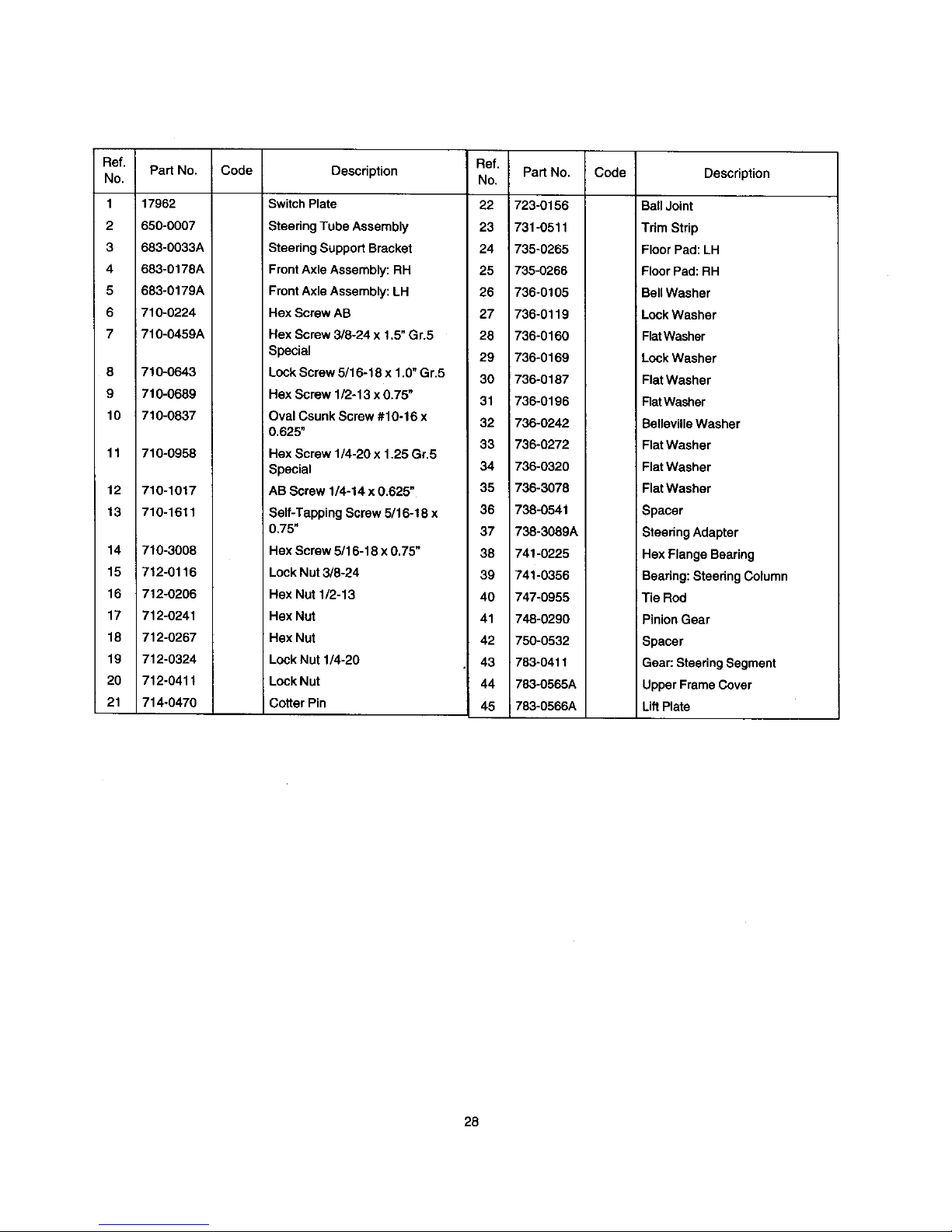
Ref.
No.
1
2
3
4
5
6
7
8
9
10
11
12
13
14
15
16
17
18
19
20
21
Part No.
17962
650-0007
683-0033A
683-0178A
683-0179A
710-0224
710-0459A
710-0643
710-0689
710-0837
710-0958
710-1017
710-1511
i710-3008
712-0116
712-0206
712-0241
712-0267
712-0324
712-0411
714-0470
Code
Description
Switch Plate
Steering Tube Assembly
Steering Support Bracket
FrontAxle Assembly: RH
Front Axle Assembly: LH
Hex Screw AB
Hex Screw 3/8-24 x 1.5" Gr.5
Special
Lock Screw 5/16-18 x 1.0"Gr.5
Hex Screw 1/2-13 x 0.75"
Oval Csunk Screw #10-16 x
0.625"
Hex Screw 1/4-20 x 1.25 Gr.5
Special
AB Screw 1/4-14 x 0.625"
Self-Tapping Screw 5/16-18 x
0.75"
Hex Screw 5/16-18 x 0.75"
Lock Nut 3/8-24
Hex Nut 1/2-13
Hex Nut
Hex Nut
Lock Nut 114-20
Lock Nut
Cotter Pin
Ref.
No.
22
23
24
25
26
27
28
29
30
31
32
33
34
35
36
37
38
39
4O
41
42
43
44
45
Part No.
723-0156
731-0511
735-0265
735-0266
736-0105
736-0119
736-0160
736-0169
736-0187
736-0196
1736-0242
736-0272
736-0320
736-3078
738-0541
738-3089A
741-0225
741-0356
747-0955
748-0290
750-0532
783-0411
783-0565A
783-0566A
Code
Description
Ball Joint
Tdm Strip
Floor Pad:LH
Floor Pad: RH
Bell Washer
LockWasher
FlatWasher
LockWasher
Flat Washer
RatWasher
BellevilleWasher
Flat Washer
Flat Washer
Flat Washer
Spacer
Steering Adapter
Hex Flange Bearing
Bearing:Steering Column
!Tie Rod
PinionGear
i Spacer
Gear: Steering Segment
Upper Frame Cover
LiftPlate
28
Page 29

Operation Control
42
15
\
10
31
37
21
3
/
,/
12
41
51
12
52
19
13
\
13
4
25
3
NOTE: For painted parts, please refer to
the list of color codes below. Please add
the applicable color code, wherever
needed, to the part number to order a
replacement part. For instance, if a part
numbered 700-xxxx 'is painted Oyster
Gray, the part number to order would be
700-xxxx-062.
Yard*Man Green: 0665
Yard-Man Yellow: 0674
Powder Black: 0637
29
Page 30

Ref.
No.
1
2
3
4
6
7
8
9
10
11
12
13
14
15
16
17
19
20
21
22
23
24
25
26
27
28
29
Pa_ No.
683-0155
683-0156
683-0275
683-0161
710-1017
711-0701
711-1156
712-0287
712-0324
712-3017
714-0104
i714-0111
714-0470
720-0166
731-0405
731-1913
732-0865
732-0815
735-0262
735-0261
735-0263
736-0117
736-0159
736-0169
736-0187
736-0272
736-0133
Description
N
Brake Pedal Assembly
Variable Pedal Assembly
Deck Pedal Assembly
Shift Cam Assembly
Ab Screw 1/4-14 X .625
Clevis Pin
Shaft
Hex Nut 1/4-20
Lock Nut 1/4-20
Hex Nut 3/8-16
Internal Cotter Pin
Hairpin Clip
Hairpin Clip '
BallKnob
Snap-on Bushing
Stop Lever
Torsion Spring
ExtensionSpring
Deck Pad
Drive Pad
Brake Pad
Flat Washer 3/8 X .620 X .033
5/16 Washer
Lock Washer
Flat Washer
Flat Washer .510 X 1.00 X .060
FlatWasher .408 x 1.25 x .tO
Ref.
No.
30
31
32
33
34
35
36
37
38
39
40
41
42
43
44
45
46
47
48
49
50
51
52
53
54
Pa_ No.
736-0329
736-0608
736-3000
736-3019
736-3020
738-0255
738-0373
738-0974
741-0591
746-0935A
746-0936
746-0937
746-0940
746-0964
747-0963
747-0964
750-0736
783-0473
783-0525
726-0450
783-0593A
783-0794
726-0157
736-0300
726-0100
N
Description
Lock Washer
Spring Washer
Flat Washer
FtatWasher .531 X 1.062 X .134
Flat Washer .271 X .630 X .065
Shoulder Screw .375 Dia X.18
Shoulder Screw
Shoulder Screw .375 X .380 X
1/4-20
Flange Bearing
Shift Cable
Vadable Drive Cable
Brake Cable
Deck Cable
Throttle Choke Cable: 67_
Brake Rod
Brake Lock Out Rod
Shoulder Spacer
Brake Lock Out Bracket
Self-Propelled Pedal Link
Plug Cap
ShiftLever
Bracket: Lock-outPedal
Cable Tie
FlatWasher .406 I.D. x .875
O.D.
Push Cap
3O
Page 31

Deck Hanger Link
5 /,
25
26
1
13
16 9
22
6 15
\
11
7\
1i
11
28
17
8
Ref.
Pa_ No.
No.
1 683-0152
2 710-0376
4 710-3230
5 711-0332
6 711-1120
7 711-3319
8 712-3008
9 712-3010
10 712-0266
11 712-3048
12 714-0104
13 714-0147
14 714-3010
15 720-0298
/
13
11
3O
4
Code
Description Ref.
No. Pa_ No.
PivotLinkAssembly 16 732-0829
Hex Screw 5/16-18 X 1.00 Gr.5 17 732-0837
Hex Bolt 1/2-13 X 2.75 Gr.5 Special 18 736-0119
Code Description
Extension Spring
Torsion Spring
Lock Washer 5/16
LiftBracket Pin 19 736-0140
LiftRod 20 736-0169
Ferrule 21 736-0275
Jam Nut 3/8-16 Gr. 5 23 738-0145
Hex Nut 5/16-18 24 738-0183
Hex Cent. Lock Nut 3/8-16 25 738-0958
Hex Jam Nut 1/2-13 Gr.5 26 783-0435
Cotter Pin 27 783-0437
Cotter Pin 28 783-0440
Cotter Pin 29 736-0257
Handle Grip 30 683-0194
N Flat Washer .385 I.D. x .620 O.D.
Lock Washer
Flat Washer 5/16
Shoulder Screw
Shoulder Screw
Shoulder Spacer
Upper Deck Link
Axle Bracket: Rear
Lower Link
N FiatWasher .526 I.D. x1.262 O,D,
Crossbar Lift Link
31
Page 32

Transaxle Assembly
j//17
3
12
5
16
Ref.
No.
!
2
3
4
5
6
7
8
9
10
11
12
13
14
15
16
17
18
19
20
Part No.
i629-0865
710-1208
710-0227
710-0805
710-0642
712-3010
714-0115
726-0320
783°0809
725-1713A
736-0289
736-0119
736-0173
760-1064
783-0433A
783-0591
683-0149A
736-3013
783-0437
729-0268
Code
N
Description
Harness Assembly Adapter
Hex'l-r Screw5/16-18 x 3.50
Hex Washer Head Self-
Tap.Scew
Hex Screw 5/16-18 x 1.5 Gr. 5
Thd. Forming Scr. 1/4-20x .75
Hex Nut 5/16-18
Cotter Pin
InsulatorNut Plate
Transaxle Support Bracket
SpringSwitch
ShoulderBushing
Lock Washer 5/16
Rat Washer
.28 I.D.x .74O,D. x .083
Spacer
ShiftLever
Transaxle Bracket
Frame Assembly
Flat Washer
Rear Axle Bracket
Insulation Connector
NOTE: For painted parts, please refer to
the list of color codes below. Please add
the applicable color code, wherever
needed, to the part number to order a
replacement part. For instance, if a part
numbered 700-xxxx is painted Oyster
Gray, the part number to order would be
700-xxxx-062.
Yard-Man Green: 0665
Yard-Man Yellow: 0674
Powder Black: 0637
32
Page 33

Variable Drive:
Ref.
No.
1
2
3
4
5
6
7
8
9
10
11
12
13
14
15
Pad No.
683-0147
710-0134
710-0191_
710-0902
710-1611
710-3096
712-0116
712-0241
712-3017
712-3035
714-0114
717-0884
732-0814
732-0815
736-0171
Code
Description
Idler Bracket Assembly
Hex Screw 3/8-24 x 1.0O
Hex Screw 3/8-24 x 1.25
Cap Screw 3/8-24 x 3.75
Pan Head TL Screw 5/16-18 x
.75
Hex Screw 3/8-16 x 2.0 Special
Jam Lock Nut3/8-24
Hex Nut 3/8-24
Hex Nut 3/8-16
Hex Jam Nut 9/16-18 (Gr. 5)
Square Key
Variable Speed Pulley Assembly
Extension Spdng
Extension Spdng
Lock Washer 7/16 I.D.
Ref.
No.
16
17
18
19
20
21
22
23
24
25
26
27
28
29
Pad No.
736-0219
736-0247
736-0427
738-0968
741-0405
750-0705
754-0453
756-0116
756-0650
756-0658
756-0981
783-0528
783-0529
736-0169
Code Description
BellWasher .406 I.D. x 1.13
O.D.
Flat Washer 3/8 x 1.25 O.D.
BellevilleWasher .567 x 1.125
x .06
ShoulderSpacer
Bearing
Spacer
V-Belt
Idler Pulley
Transmission Pulley
Engine Pulley
Flat Idler Pulley
Idler Bracket
Cable Bracket
LockWasher 3/8 I.D.
33
Page 34

Upper Frame
17
18
17
17
9
25
14 1
35
28
3
32
Ref.
No.
1
3
4
5
6
8
9
10
11
12
14
15
16
17
18
19
2O
Part No. Code Description Ref.
No.
783-0605 Deck Stabilizing Bracket 21
783-0564A N Front Frame: Upper 22
783-0811 N Steering Gear Cover 23
683-0264 N Front Channel Assembly 25
783-0554 Cam Bracket 26
783-0414A Frame Rail: Rear 27
783-0413 Frame RaiI--L. H. 28
783-0412A N Frame RaiI--R.H. 29
747-0985 Deck Rod 30
736-3019 Flat Washer .531 X 1.062 X .134 31
736-0275 Flat Washer 5/16 32
736-0187 Flat Washer .64 I.D. X 1.24 X .06 33
736-0101 Flat Washer 3/8 X 1.00 X .030 34
735-0271 Rubber Bumper 35
735-0199A Rubber Bumper 36
732-0829 Extension Spring 37
726-0272 Clamp: 9/16 dia,
38
Part No.
725-0157
714-0470
714-0147
714-0104
712-0271
i712-0265
711-1165
711-0332
710-1611
710-1017
710-0599
683-0163A I
683-0160
683-0142
749-1099
712-0431
710-0514
Code
Description
Cable Tie
HairpinClip
HairpinClip
HairpinClip
Hex Nut
Hex Nut 1/4-20
Clevis Pin
LiftBracket Pin
TT Screw 5/16-18 x .75
Torx Mach, AB Scr. 1/4-14 x0.625"
Hex l-r Screw 1/4-20
Steering SupportBracket
Pivot Bracket Ass'y.: Hood
PivotBar Assembly
FrontBumper (Optional)
LockNut 3/8-16"
Hex Bolt3/8-16 x 1.0"Gr. 5*
*Applicable only with the optional bumper tube (reference no. 36)
34
Page 35

Frame Assembly
10
44
44 \
33
16
\
15
\
43
14
7
2
2O
34
/
24
2O
NOTE: For painted parts, please refer to
the list of color codes below. Please add
the applicable color code, wherever
needed, to the part number to order a
replacement part. For instance, if a part
numbered 700-xxxx is painted Oyster
Gray, the part number to order would be
700-xxxx-062.
Yard-Man Green: 0665
Yard-Man Yellow: 0674
Powder Black: 0637
35
Page 36

Ref.
No.
1
2
3
4
5
6
7
8
9
10
11
12
13
14
15
16
17
18
19
20
21
22
Pad No.
683-0149A
683-0190
683-0191
683-o192
710-0148
71o-o157
7t0-0624
710-0654A
710-0871
710-1237
710-1611
710-1653
710-3015
71!-0222A
712-0271
712-0291
712-0397
712-3017
712-3057
725-0157
i726-0205
726-0209
Code
Description
Frame Assembly
Frame Rail Support: RH
Frame Rail Support: LH
Muffler Pipe Extension
Hex FI. Screw #8-32 x 0.375
Hex Screw 5/16-24 x .75"Gr.5
Hex Screw 5/16-24 x 1.5"Gr.5
Hex Washer Head TT Screw 3/8-
Ref.
Pad No.
No.
23 731-0708
24 731-1682A
25 731-1945
26 732-3080
27 735-0273
28 736-0119
29 736-0123
30 736-0159
Code
Description
Battery Cover
Oil Drain Sleeve
Engine Duct
Compression Spnng
RubberWasher
LockWasher
FlatWasher
5/16Washer
16x 1.0"
Hex Slot Sems Screw#10-32 x
0.38
Hex Washer "IT Screw #10-32 x
0.625"
"IT Screw 5/16-18 x 0.75"
MachineScrew #10-32 x 0.5"
Hex Screw 1/4-20 x 0.75"
Battery Hold-down Rod
Hex Sems Nut 1/4-20
LockNut 1/4-20
Wing Nut with BellWasher
Hex Nut
Hex Nut 5/16-24 Gr.5
Cable Tie
Hose Clamp
Cable Tie
31
32
33
34
35
36
37
38
39
40
41
42
43
44
45
46
47
736-0169
736-0188
736-0400
736-0607
737-0169
738-0960
741-0516
741-0591
751B213146
751-0535
751-0656
783-0417
783-0624
783-0630
783-0561
710-0118
712-0267
LockWasher
Flat Washer
Fiat Washer
Lock Washer
Motor Oil
ShoulderScrew
Flange Bearing
FlangeBearing
ThrottleCasing Clamp
FuelLine Hose
FuelTank
Transaxle Support Bracket
Battery Bracket
Fuel Tank Bracket
Hitch Plate (Optional)
Hex Bolt*
Hex Nut*
*Applicable only with the optional hitch plate (reference no. 45)
36
Page 37

Hood Assembly
A
17
NOTE: For painted parts, please refer to
the list of color codes below. Please add
the applicable color code, wherever
needed, to the part number to order a
replacement part. For instance, if a part
numbered 700-xxxx is painted Oyster
Gray, the part number to order would be
700-xxxx-062.
Yard-Man Green: 0665
Yard-Man Yellow: 0674
Powder Black: 0637
B
9
11
10
Ref. Part No.
No.
1 710-0599
2 710-0870
3 710-1017
4 720-0238
5 720-3026
6 731-0511
7 731-1691
8 783-0410
I
Code
Description
Hex Hd. l-r Screw 1/4-20
x 0.5
Hex Washer Hd. "IF
Screw 3/8-16 x 0.62
Torx Head AB screw 1/4-
14 x 0.625
Rod End Grip
Edge Trim
Trim Strip
Grass Bag Lens
Bracket Reinforcement:
Hood
Ref. Part No.
No.
9 783-0445
10 783-O446
11 783-0447
12 783-0448
13 783-0449
14 783-0451A
15 783-0545
16 783-0562
17 757-0364A
Code
Description
Hood
Plate: Hood
Hood Bracket
Hood Bracket:
Reinforcement
Hinge Bracket: Rear
Pivot Plate: Rear Hood
Hood Screen
Hinge Bracket: Front
Seat
37
Page 38

Wheel Assembly
\
6
2
4
Ref.
No.
1
2
3
4
5
6
7
8
Pad No.
737-0288
736-0285
736-0242
714-0115
710-0627
634-0139
634-0169
736-0366
Code
N
Description
Grease Fitting (Not Shown)
Flat Washer ,635 x 1.589 x .060
BellWasher .345 I.D. x .88 O.D,
x.06
Hairpin Clip
Hex Screw 5/16-24 x .75
Rear Wheel 16.0 x 6.5 x 8.0
FrontWheel 11.0 x 4.0 x 4,0
Flat Washer 5/8 I.D. x 1.00.D.
Ref.
No.
1
2
3
Pad NO.
727-0425A
731-1825
734-1788A
Code Description
Spdng Clip
Hubcap: Yellow---4.0"
Hubcap:Yellow--8"
38
Page 39

Three-In-One Mowing Deck
17
34
14 28"_
NOTE: For painted parts, please refer to
the list of color codes below. Please add
the applicable color code, wherever
needed, to the part number to order a
replacement part. For instance, if a part
numbered 700-xxxx is painted Oyster
Gray, the part number to order would be
700-xxxx-062.
Yard-Man Green: 0665
Yard-Man Yellow: 0674
Powder Black: 0637
39
Ref.
No.
1
2
3
4
5
6
7
8
9
10
11
12
13
14
15
16
17
18
19
20
21
22
23
24
25
26
27
28
29
30
31
32
33
34
35
36
37
38
39
40
Part No.
618-0250
683-0150C
683-0159
683-0173
747-1172
710-0134
710-0191
710-0347
710-0599
710-0650
710-0672
710-1611
712-0241
712-0287
712-0397
;712-0417A
712-3017
712-3057
714_0470
726-0201
726-0233
732-0429AI
736-0101
736-0119
736-0169
736-0289
736-0300
736-0329
736-0343
738-0968
742-0651
747-0957
747-0972
754-0754
756-0627
789-0463
753-0529
783-0569A
783-0781
783-0594
Code
N
N
N
Description
Spindle Assembly
Deck Assembly
Brake Bracket Assembly
Deck Belt Cover
Belt Keeper
Carriage Screw 1/4-20 x 62
Hax Bolt 3/8-24 x 1.25 Grade 8
Hex Screw 3/8-16 x 1.75 Gr. 5
Self-Tapping Washer Head
Hex Screw 1/4-20 x .5
Hex Washer Self-Tapping
Screw 5/16-18 x .75
HexCap Scr.5/1624 x 1.25 (Gr.5)
Tom Head Screw 5/16-18 x .75
Hex Nut 3/8-24
Hex Nut 1)4-20
Wing NutWith BellWasher
Flange Nut 5/8-18
Hex Nut 3/8-16
Hex Nut5/16-24
Cotter Pin
Speed Nut
PushNut
Extension Spring
Flat Washer 3/8 x 1.00 x .030
LockWasher 5/16
LockWasher 3/8
Bushing
Flat Washer .406 x .875 x .059
LockWasher
Flat Washer .330 x 1.25 x .120
Spacer
Three-in-one Blade
Link Rod
Belt Keeper
V Belt
Flat Idler Pulley
IdlerBracket
Cable Bracket
Deck Plate
Deck Skirt
Deck Cable Bracket
Page 40

Deck Accessory--Three-In-One
16
9
Raf.
No.
1
2
3
4
5
6
7
8
9
10
11
12
13
14
15
16
17
18
19
20
21
22
23
24
25
26
27
Pa_ No.
i631-0060
631-0080
710-0166
710-0286
710-0456
710-0564
710-0642
710-0825
710-0924
711-0415
712-0271
712-0298
712-0397
714-0115
726-0271
731-1441
731-1743A
731-1744
731-1745A
732-0839
732-0841
732-0854
736-0173
736-0329
783-0544
783-0575A
783-0645
Code
N
Description
Flow IndicatorAssembly
Grass Bag Assembly
Machine Screw 1/4-20 x 1.0
Machine Screw 1/4-20 x 0.5"
Hex Screw #10-16 x 0,5"
Hax Screw 1/4-20 x 2.75"
Self-Tapping Screw 1/4-20 x
0.75"
Hex Screw 1/4-20 x 3.75"
Machine Screw 1/4-20 x 0.75"
Clevis Pin
Hex Sems Nut 1/4-20
Jam Nut
Wing Nut
Cotter Pin
Speed Nut
Bag Handle
Discharge Chute: Grass Bag
Side-Discharge Chute
Mulching Plug
BagReleaseLever
Torsion Spring
Clip Spring
RatWasher
LockWasher
Grass Bag Screen
PivotBracket
DeflectorPlate
12
18
4O
Page 41

Wire Diagram
ENGINE
YELLOW
RED/WHITE
RED
c
11
IGNITION SW >
z
725-3'267
'11
RED/WHT
YELLOW
ORG/BLK , "_
RED
RED
PTO SWITCH
725-1657A
T GREEN
BATTERY
725-1698
BRAKESW
725-1657A
RED
SOLENOID L
72_1426
FUSE
725-1381
GREEN
YEUBLK
GREEN
SE*R"SWITCH
725-3234
BATrERY BOOT COVER
725-1727
o-Ill,
REVERSE SW
725-1643
YEIJBLK
RELAY 1 RELAY
725-1648 725-1648
COMPLETE WIRE HARNESS (629-0902)
41
Page 42

Single Speed Transmission--L.H. (Part No. 618-0251A)
¢
\
42
Page 43

Ref.
nO.
1
2
3
4
5
6
7
8
9
10
11
12
13
14
Part No. Code Description
618-0232
i 618-0248
618-0072B
611-0114
661-0006
710-1206
710-1325
717-0678
719-0313B
732-0863
737-0148
741-0862
761-0202
777-6318
Differential Assembly: Single Speed
Drive Shaft assembly: LH Brake
Upper Housing Assembly
Detent Shaft Assembly
Brake Yoke Assembly: LH
Hex Washer Hd. "1-1"Screw 114-20 x 2.37 Gr.5
Hex Washer Hd. "17"Screw 1/4-20 x 1.65
Brake Puck
Lower Housing
Spring Detent
Grease
Ball Detent
Brake Disc
Label
43
Page 44

MANUFACTURER'S LIMITED WARRANTY FOR:
YaRD-MaN.)/f
For TWO YEARS from the date of retail purchase
within the United States of America, its possessions
and territories, MTD PRODUCTS INC will, at its
option, repair or replace, for the original purchaser,
free of charge, any part or parts found to be
defective in material or workmanship. This warranty
covers units which have been operated and
maintained in accordance with the operating
instructions furnished with the unit, and which have
not been subject to misuse, abuse, commercial use,
neglect, accident, improper maintenance or
alteration.
Units exported out of the United States: MTD
PRODUCTS INC does not extend any warranty for
products sold or exported outside of the United
States of America, its possessions and territories,
except those sold through MTD PRODUCTS INC's
authorized channels of export distribution.
Other Warranties:
1,
Normal wear parts or components thereof are 2.
subject to separate terms as noted below in the "No
Fault Ninety Day Consumer Warranty" clause. 3.
All normal wear part failures will be covered on this
product for a period of 90 days regardless of cause.
After 90 days, but within the two year period, normal 4.
wear parts failures will be covered ONLY IF caused
by defects in material or workmanship of OTHER
component pads. Normal wear parts are defined as
batteries*, belts, blades, blade adapters, grass bags,
rider deck wheels, seats, snow thrower skid shoes, 5.
shave plates and tires.
How to obtain service: Warranty service is
available, with proof of purchase, through your local
authorized service dealer. To locate the dealer in
your area, please check the yellow pages or contact
the Customer Service Department of MTD
PRODUCTS INC, P. O. Box 368022, Cleveland,
Ohio 44136-9722. Phone 1 (800) 800-7310. The
return of a complete unit will not be accepted by the
factory unless prior written permission has been
extended by the Customer Service Department of
MTD PRODUCTS INC.
Transportation charges: Transportation charges
for the movement of any power equipment unit or
attachment are the responsibility ofthe purchaser.
The engine or component parts thereof carry
separate warranties from their manufacturers.
Please refer to the applicable manufacturer's
warranty on these items.
*Batteries are covered by a 90-day replacement
warranty.
Log splitter pumps, valves and cylinders or
component parts thereof are covered by a one
year warranty.
All other warranties, express or implied,
including any implied warranty of merchantability
or fitness for a particular purpose, are hereby
expressly disclaimed in their entirety.
The provisions as set forth in this warranty
provide the sole and exclusive remedy of MTD
PRODUCTS INC's obligations arising from the
sales of its products. MTD PRODUCTS INC will
not be liable for incidental or consequential loss
or damage.
How state law relates to this warranty: This
limited warranty gives you specific legal rights, and
you may also have other rights which vary from state
to state. Certain disclaimers are not allowed in some
states and therefore they may not apply to you
under all circumstances.
NOTE: This warranty does not cover routine
maintenance items such as lubricants, filters, blade
sharpening and tune-ups, or adjustments such as
brake adjustments, clutch adjustments or deck
adjustments. Nor does this warranty cover normal
detedoration of the exterior finish due to use or
exposure.
 Loading...