

OPERATOR’S MANUAL
Cultivator
Model Number
21A-144R401
IMPORTANT: READ SAFETY RULES AND INSTRUCTIONS CAREFULLY
Warning: This unit is equipped with an internal combustion engine and should not be used on or near any unimproved forest-
covered, brush-covered or grass-covered land unless the engine’s exhaust system is equipped with a spark arrester meeting
applicable local or state laws (if any). If a spark arrester is used, it should be maintained in effective working order by the operator.
In the State of California the above is required by law (Section 4442 of the California Public Resources Code). Other states may have
similar laws. Federal laws apply on federal lands. A spark arrester for the muffler is available through your nearest engine authorized
service dealer or contact the service department, P.O. Box 368022 Cleveland, Ohio 44136-9722.
MTD PRODUCTS INC. P.O. BOX 368022 CLEVELAND, OHIO 44136-9722
PRINTED IN U.S.A.
FORM NO.
770-10457.fm
(5/02)

TABLE OF CONTENTS
Content Page
Important Safe Operation Practices...................................................................3
Assembling Your Cultivator................................................................................5
Know Your Cultivator ......................................................................................... 5
Operating Your Cultivator .................................................................................. 6
Maintaining Your Cultivator................................................................................ 8
Troubleshooting.................................................................................................11
Parts List............................................................................................................12
FINDING MODEL NUMBER
This Operator’s Manual is an important part of your new cultivator. It will help you assemble, prepare and
maintain the unit for best performance. Please read and understand what it says.
Before you start assembling your new equipment, please locate the model plate on the
equipment and copy the information from it in the space provided below. The information on
the model plate is very important if you need help from our Customer Support Department or
an authorized dealer.
• You can locate the model number by looking down in front of the engine on the cultivator. A sample
model plate is explained below. For future reference, please copy the model number and the serial
number of the equipment in the space below.
(Model Number)
(Serial Number)
MTD PRODUCTS INC
CLEVELAND, OHIO 44136
Copy the model number here:
Copy the serial number here:
CALLING CUSTOMER SUPPORT
If you have difficulty assembling this product or have any questions regarding the controls, operation or
maintenance of this unit, please call the Customer Support Department.
Call 1- (330) 220-4MTD (4683) or 1- (800)-800-7310 to reach a Customer Support
representative. Please have your unit’s model number and serial number ready when you
call. See previous section to locate this information. You will be asked to enter the serial
number in order to process your call.
For more details about your unit, visit our website at www.yardman.com
2

SECTION 1: IMPORTANT SAFE OPERATION PRACTICES
WARNING: This symbol points out important safety instructions which, if not followed, could
endanger the personal safety and/or property of yourself and others. Read and follow all instructions in
this manual before attempting to operate this machine. Failure to comply with these instructions may
result in personal injury. When you see this symbol - heed its warning.
WARNING: The Engine Exhaust from this product contains chemicals known to the
State of California to cause cancer, birth defects or other reproductive harm.
DANGER: This machine was built to be operated according to the rules for safe operation in this
manual. As with any type of power equipment, carelessness or error on the part of the operator can
result in serious injury. This machine is capable of amputating hands and feet and throwing objects.
Failure to observe the following safety instructions could result in serious injury or death.
Training
1. Read, understand, and follow all instructions on the
machine and in the manual(s) before attempting to
assemble and operate. Keep this manual in a safe
place for future and regular reference and for
ordering replacement parts.
2. Be familiar with all controls and their proper
operation. Know how to stop the machine and
disengage them quickly.
3. Never allow children under 14 years old to operate
this machine. Children 14 years old and over
should read and understand the operation
instructions and safety rules in this manual and
should be trained and supervised by a parent.
4. Never allow adults to operate this machine without
proper instruction.
5. Keep bystanders, helpers, pets, and children at
least 50 feet from the machine while it is in
operation. Stop machine if anyone enters the area.
PREPARATION
1. Thoroughly inspect the area where the equipment
is to be used. Remove all stones, sticks, wire, and
other foreign objects which could be tripped over
and cause personal injury.
2. Wear sturdy, rough-soled work shoes and closefitting slacks and shirts. Loose fitting clothes or
jewelry can be caught in movable parts. Never
operate this machine in bare feet or sandals.
3. Wear safety glasses or goggles that are marked as
meeting ANSI Z87.1 standards and ear/hearing
protection when operating this unit. Wear a face or
dust mask if the operation is dusty.
4. This unit has a clutch. The tines remain stationary
when the engine is idling. If they do not, have the
unit adjusted by an authorized service dealer.
5. Squeeze the throttle control and check that it
returns automatically to the idle position.
6. Never leave this machine unattended with the
engine running.
7. Never attempt to make any adjustments while
engine is running, except where specifically
recommended in the operator’s manual.
8. To avoid personal injury or property damage use
extreme care in handling gasoline. Gasoline is
extremely flammable and the vapors are explosive.
Serious personal injury can occur when gasoline is
spilled on yourself or your clothes which can ignite.
Wash your skin and change clothes immediately.
a. Use only an approved gasoline container.
b. Extinguish all cigarettes, cigars, pipes, and
other sources of ignition.
c. Never fuel machine indoors.
d. Never remove gas cap or add while the
engine is hot or running.
e. Allow engine to cool at least two minutes
before refueling.
f. Never over fill fuel tank. Fill tank to no more
than 1/2 inch below bottom of filler neck to
provide space for fuel expansion.
g. Replace gasoline cap and tighten securely.
h. If gasoline is spilled, wipe it off the engine
and equipment. Move machine to another
area. Wait 5 minutes before starting the
engine.
i. Never store the machine or fuel container
inside where there is an open flame, spark,
or pilot light (e.g. furnace, water heater,
space heater, clothes dryer, etc.)
j. Allow machine to cool at least 5 minutes
before storing.
OPERATION
1. Do not put hands and feet near rotating parts.
Contact with the rotating parts can amputate
fingers, hands, and feet.
2. Do not operate machine while under the influence
of alcohol or drugs.
3. Never operate this machine without good visibility
or light. Always be sure of your footing and keep a
firm hold on the handles.
3

4. Keep bystanders, helpers, pets, and children at
least 50 feet from the machine while it is in
operation. Stop machine if anyone enters the area.
5. Be careful when cultivating in hard ground. The
tines may catch in the ground and propel the
cultivator forward. If this occurs, let go of the handle
and do not restrain the machine.
6. Never operate the machine at high transport
speeds on hard or slippery surfaces.
7. Exercise caution to avoid slipping or falling.
8. Look down, behind, and use care when pulling
machine towards you.
9. Start the engine according to the instructions found
in this manual and keep feet well away from the
tines at all times.
10. After striking a foreign object, stop the engine,
disconnect the spark plug wire and ground against
the engine. Thoroughly inspect the machine for any
damage. Repair the damage before starting and
operating.
11. Disengage all clutch and stop engine before you
leave the operating position (behind the handle).
Wait until the tines come to a complete stop before
unclogging the tines, making any adjustments, or
inspections.
12. Never run an engine indoors or in a poorly
ventilated area. Engine exhaust contains carbon
monoxide, an odorless and deadly gas.
13. Muffler and engine become hot and can cause a
burn. Do not touch.
14. Use caution when cultivating near fences, buildings
and underground utilities. Rotating tines can cause
property damage or personal injury.
15. Do not overload machine capacity by attempting to
cultivate soil to deep or to fast of a rate.
16. If the machine should start making an unusual
noise or vibration, stop the engine, disconnect the
spark plug wire and ground it against the engine.
Inspect thoroughly for damage. Repair any damage
before starting and operating.
17. Keep all shields, guards and safety devices in place
and operating properly.
18. Never pick up or carry machine while the engine is
running.
19. Use only attachments and accessories approved
by the manufacturer. Failure to do so, can result in
personal injury.
20. If situations occur which are not covered in this
manual, use care and good judgment. Contact your
dealer or telephone 1-800-800-7310 for assistance
and the name of your nearest servicing dealer.
Maintenance And Storage
1. Never tamper with safety devices. Check their
proper operation regularly.
2. Check bolts and screws for proper tightness at
frequent intervals to keep the machine in safe
working condition. Also, visually inspect machine
for any damage.
3. Before cleaning, repairing, or inspecting, stop the
engine and make certain the tines and all moving
parts have stopped. Disconnect the spark plug wire
and ground it against the engine to prevent
unintended starting.
4. Do not change the engine governor settings or
over-speed the engine. The governor controls the
maximum safe operating speed of the engine.
5. Maintain or replace safety and instruction labels, as
necessary.
6. Follow this manual for safe loading, unloading,
transporting, and storage of this machine.
7. Never store the machine or fuel container inside
where there is an open flame, spark or pilot light
such as a water heater, furnace, clothes dryer etc.
8. Always refer to the operator’s manual for proper
instructions on off-season storage.
9. If the fuel tank has to be drained, do this outdoors.
10. Observe proper disposal laws and regulations for
gas, oil, etc. to protect the environment.
WARNING: Restrict the use of this power
machine to persons who read, understand
and follow the warnings and instructions in
this manual and on the machine.
NOTE: Not all safety labels may apply to your cultivator.
4
SECTION 2: ASSEMBLING YOUR CULTIVATOR
IMPORTANT:
in the engine. Be certain to service engine with gasoline
and oil as instructed in the separate engine manual
before operating your mower.
NOTE: Reference to right or left hand side of the
cultivator is observed from the operating position.
This unit is shipped without gasoline or oil
Removing Unit From Carton
• Remove staples, break glue on top flaps, or cut
tape at carton end and peel along top flap to open
carton.
• Remove loose parts if included with unit (e.g.,
operator’s manual, safety glasses, etc.)
• Cut along corners, lay carton down flat, and remove
packing material.
• Roll or slide unit out of carton and check carton
thoroughly for loose parts.
Disconnecting Spark Plug Wire
Before setting up your cultivator, disconnect the spark
plug wire from the spark plug and ground to a stud on
the engine.
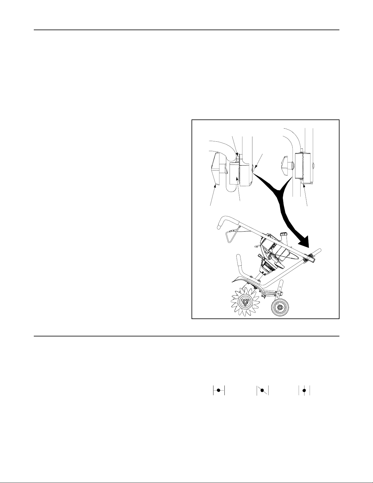
• Position the connectors aligning the marked line on
the upper connector with the middle marked line on
the lower connector.
• To secure the upper and lower handle, tighten the
wing nuts and washers (carriage bolts must be
seated properly into the handle and grooves must
line up between connectors).
• Tighten the cable ties on the left side of handle.
Marked
Lines
Carriage
Bolt
Wing Nut
Lower Handle
Connector
Upper Handle
Connector
Setting Up Your Cultivator
• Loosen each wing nut enough to separate the
plastic connectors between the upper and lower
handle. Gently lift up and pull back on the upper
handle to raise the handle toward the operating
position. See Figure 1.
• Separate the connectors and position the bottom
tip of upper handle connector in front of the bottom
tip of lower handle connector.
• The lower handle connector has three marked lines
on the top and the upper handle connector has one
marked line.
SECTION 3: KNOW YOUR CULTIVATOR
Read this operator’s manual and safety rules before
operating your cultivator. Compare the illustrations in
Figure 2 with your cultivator to familiarize yourself with
the location of various controls and adjustments. Save
this manual for future reference.
Starter Handle
The starter handle is attached to an eyebolt in the front
of the engine.
Throttle Lever
The throttle lever is located on the upper handle.
Squeezing the lever against handle speeds up the
engine and engages the cultivator tines. Release the
handle to stop the tines.
Figure 1
Choke Lever
The choke lever is located on the right side of engine
and it is used to enrich the fuel mixture when starting a
cold engine.
A
Close
B
Partial
C
Open
Primer Button
The primer button is located on the right side of engine
and it is used in conjunction with the choke to enrich the
fuel mixture in the carburetor when starting a cold
engine.
5

On/Off Switch
The On/Off switch is located on the upper handle. The
switch must be in the On (I) to start engine and Off (O)
to stop engine.
Handle Connectors
The handle connectors are on each side between lower
and upper handle. They are used to lock the upper
handle in a set position.
Front Handle
The front handle is used as support when grasping the
starter handle during starting.
Tines
The tines are used to cultivate, furrow, and prepare
your garden for seeding.
On/Off Switch
Handle
Connectors
Wheel Support Bracket
The wheel support bracket is attached to the tailpiece
bracket behind the cultivator. It is used to adjust the
wheels to a higher or lower resting position.
Edger Wheel and Blade
The edger wheel and blade are separate parts that do
not come attached on the cultivator. The are to be used
instead of the cultivator tines for vertical edging.
Stopping Engine
• Push the On/Off switch to Off (O) position to stop
engine and tines.
• Disconnect spark plug wire from spark plug and
ground against the engine.
Throttle Lever
Primer
Starter Handle
Front Handle
Choke Lever
Cultivator
Tines
Figure 2
SECTION 4: OPERATING YOUR CULTIVATOR
Oil Fill-Up
Using the proper type and weight of oil in the crankcase
is extremely important. Check the oil before each use
and change the oil regularly. Failure to use the correct
oil or using dirty oil can cause premature engine wear
and failure.
Use a high-quality SAE 30 weight oil of API (American
Petroleum Institute) service class SF, SG, or SH.
NOTE: This unit is shipped without oil in the engine. In
order to avoid damage to the unit, put the
recommended oil in the crankcase before attempting to
start unit.
This unit is shipped with one 3.4 fluid oz. (100ml) bottle
of SAE 30 SF, SG, or SH oil.
NOTE: This cultivator is shipped for operation in
conditions above 40°F (4°C). For cold weather
operation, temperatures below 40°F (4°C) use a highquality SAE 10W30 weight oil of API (American
Petroleum Institute) service class SF, SG, or SH.
• Lay the cultivator back in a horizontal position on a
flat level surface with the upper handle touching the
ground.
6
Edger Wheel
Edger Blade

• Remove the oil plug/dipstick from the crankcase
and pour the entire bottle of oil into the oil fill hole.
See Figure 3.
• Wipe up any oil that may have spilled and reinstall
the oil fill plug/dipstick.
DipStick
Fuel Cap
Figure 3
Gas Fill-Up
Old fuel is the primary reason for the unit not running
properly. Be sure to use fresh, clean, and unleaded
gasoline. Use fresh fuel (less than 60 days old), when
using alcohol-blended fuel.
Starting Engine
• Attach spark plug wire to spark plug. Make certain
the metal cap on the end of the spark plug is
fastened securely over the metal tip on the spark
plug.
• Push On/Off switch on upper handle to On (I).
• Place choke lever in Close (A) position.
See Figure 4.
• Fully press and release the primer bulb slowly 5 to
7 times. Gasoline should be felt and visible in the
bulb. Press primer a few more time, if gasoline is
not noticed. See Figure 4.
Choke Lever
Primer Bulb
NOTE: This is a 4-cycle engine. In order to avoid
damage to the unit, do not mix oil with gasoline.
Fuel Additives
The use of fuel additives or gas stabilizer will inhibit corrosion and minimize the formation of gum deposits.
Using a fuel additive can keep fuel from forming harmful
deposits in the carburetor for up to six (6) months. Add
0.8 oz. (23ml) of fuel additive per gallon of fuel according to the instructions on the container. Never add fuel
additives directly to the unit’s gas tank.
• Lay the cultivator back in a horizontal position on a
flat level surface with the upper handle touching the
ground.
• Remove fuel cap and remove the tag from the fuel
tank neck. Refer to Figure 3.
WARNING: Use extreme care when
handling gasoline. Gasoline is extremely
flammable and the vapors are explosive.
Never fuel machine indoors or while the
engine is hot or running. Extinguish
cigarettes, cigars, pipes, and other
sources of ignition.
• Place spout of gas container into the fill hole on the
fuel tank and fill tank.
• Wipe up any gasoline that my have spilled and
reinstalled the fuel cap.
• Move the unit at least 30 ft. (9.1m) from the fueling
source and site before starting the engine.
Figure 4
• With one hand grasping the starter handle, the
other hand should grasp the front handle on the
cultivator for a brace.
• Pull the starter rope briskly 3 to 5 times or until
engine attempts to run.
• Move the choke to Partial (B) position.
NOTE: The engine will not operate in the Open (A)
position.
• Pull the starter rope again 1 to 3 times until engine
starts.
• Move choke lever to Open (C) position.
• With tines off the ground, depress the throttle lever
against the upper handle to increase engine speed
and rotate tines.
WARNING: Never run the engine indoors
or in a poorly ventilated area. Engine
exhaust contains carbon monoxide, an
odorless and deadly gas. Keep hands,
feet, hair, and loose clothing away from
rotating tines.
Starting A Warm Engine
• Push On/Off switch on upper handle to On (I).
• Move the choke to Partial (B) position.
• Fully press and release the primer bulb slowly 5 to
7 times. Gasoline should be felt and visible in the
bulb. Press primer a few more time, if gasoline is
not noticed. See Figure 4.
7

• With one hand grasping the starter handle, the
other hand should grasp the front handle on the
cultivator for a brace.
• Pull the starter rope briskly 3 to 5 times or until
engine starts.
• Move choke lever to Open (C) position.
• With tines off the ground, depress the throttle lever
against the upper handle to increase engine speed
and rotate tines.
Clevis Pin
Cotter Pin
Wheel Support
Bracket
Tailpiece Bracket
Using Your Cultivator
WARNING: Never pick-up or carry the unit
while the engine is running. Serious
personal injury could result.
• Move the cultivator to the work area prior to starting
the engine. The cultivator may be transported by
pushing it on the wheels or carrying it by the
handles.
• Start the engine referring to Starting Engine.
• With both hands on the upper handle and
squeezing the throttle control, slowly lower the
cultivator until the tines make contact with the
ground.
• Once the tines are in the ground, continue to
cultivate at a moderate pace until you are familiar
with the controls and the handling of the cultivator.
• To adjust the cultivating depth, adjust the wheel
support bracket. See Adjusting The Wheel Bracket.
For cultivation, a two to three inch depth is desirable.
When laying out plant rows, be sure to allow enough
width to permit cultivation between the rows. In growing
corn or similar crops, check-row planting will permit
cross cultivation and practically eliminate hand hoeing.
Adjusting the Wheel Support Bracket
To adjust the wheel support bracket proceed as follows:
• Stop engine and disconnect spark plug to avoid
accidental starting.
• Remove cotter pin from the clevis pin and slide pin
out of tailpiece bracket. See Figure 5.
• Slide the wheel support bracket up or down in the
tailpiece, aligning the holes to the desire height.
• Place the clevis pin through the hole and secure
with a cotter pin.
Figure 5
Attaching the Edger Wheel And Blade
To convert the cultivator to an edger proceed as
follows:
• Push the On/Off switch to Off (O) position to stop
engine and tines and disconnect spark plug to
avoid accidental starting.
• It may be necessary to lay the cultivator back in a
horizontal position on a flat level surface with the
upper handle touching the ground.
• Remove the click pin from each end of the tine shaft
and slide the tines off the shaft.
• Slide the edger wheel on the right side of the tine
shaft and secure with the click pin in the inside hole.
See Figure 6.
• Slide the edger blade with the hub facing out on the
left side of tine shaft and secure with the click pin in
the inside hole. See Figure 6.
Hub
Click Pin
Edger Wheel
Edger Blade
Figure 6
• Guide cultivator/edger along a flowerbed, garden,
sidewalk, or driveway with the edger wheel along
the outside edge.
SECTION 5: MAINTAINING YOUR CULTIVATOR
WARNING: Always stop engine and
disconnect spark plug wire before
cleaning or doing any kind of maintenance
on your cultivator.
Tine Removal and Replacement
NOTE: All four tines should be replaced at the same
time, because they will wear evenly through normal
use.
8

• Push the On/Off switch to Off (O) position to stop
engine and tines and disconnect spark plug to
avoid accidental starting.
• It may be necessary to lay the cultivator back in a
horizontal position on a flat level surface with the
upper handle touching the ground.
• Remove the click pin from each end of the tine shaft
and slide the tines off the shaft.
• Slide new tines on with hubs facing out. The four
tines are marked with letters A and B and an A and
a B tine must be on the same side. See Figure 7.
• Secure new tines to shaft with click pins.
B Tine
A Tine
Click Pin
Hubs
NOTE: It may be necessary to wash the dirt off the tines
and shaft for ease of removal.
Engine Maintenance
Customer Responsibilities
e
s
u
h
MAINTENANCE
SCHEDULE
Fill Fuel Tank
Check Oil
E
Change Oil
N
I
G
Clean Air Filter
N
E
Check Spark Plug
Check Spark Arrester (if any)
c
a
e
e
r
o
f
e
B
2
y
r
e
v
E
Gas Fill-Up
Refer to the operation section.
Figure 7
s
n
s
s
r
u
o
h
5
u
o
h
0
5
y
r
e
v
E
E
r
r
u
o
h
0
0
1
y
r
e
v
s
a
e
s
a
e
c
n
B
O
e
o
g
a
r
o
t
s
e
r
o
f
e
SERVICE
DATES
• If the level is low, add a small amount of oil to the oil
fill hole and recheck. Repeat until the oil level
reaches the top of the dipstick. See Figure 8.
Checking Oil
WARNING: To prevent extensive engine
wear and damage to the unit, always
maintain the proper oil level in the
crankcase. Never operate the unit with the
oil level below the bottom of the dipstick.
• Stop engine and allow oil to drain into the
crankcase.
• Lay the cultivator back in a horizontal position on a
flat level surface with the upper handle touching the
ground.
• Keep dirt and debris out of the engine. Clean the
area around the oil fill plug/dipstick before removing
it.
• Remove the oil fill plug/dipstick and wipe off oil.
Reinsert it all the way back in.
• Remove the oil fill plug/dipstick and check oil level.
Oil should be up to the top of the dipstick.
Refer to Figure 3.
O-Ring
Full
Oil Fill
Plug/Dipstick
Figure 8
NOTE: Make sure the O-ring is in place on the oil fill
plug/dipstick when checking and changing the oil.
Changing Oil
• Remove the oil fill plug/dipstick.
• Tip the unit back or away from the air filter to pour
the oil out of the oil fill hole and into a container.
• Wipe up any oil residue on the unit and clean up
any oil that may have spilled. Dispose of the oil
according to federal, state, and local regulations.
9

• Refill the crankcase with 3.4 fl.oz. (100 ml.) of SAE
30 SF, SG, or SH oil.
• Replace the oil fill plug/dipstick.
Air Filter Maintenance
• Open the air filter cover on side of engine by
pushing the tab on the left side in and swinging the
air filter cover out and off. See Figure 9.
• Remove the air filter and screen.
Air Filter
Screen
Air Filter
• Wash the filter in detergent and water. Rinse the
filter thoroughly and allow it to dry.
• Apply enough clean SAE 30 motor oil to lightly coat
the filter and squeeze the filter to spread and
remove excess oil.
• Replace the screen and filter.
• Position the hooks on the right side of the air filter
cover into the slots at the right side of the air filter
housing.
• Swing the cover to the left until the tab on the air
filter cover snaps into place in the slot.
Air Filter
Housing
Air Filter Cover
Tab
Figure 9
Carburetor Adjustment
If the engine will not idle, hesitates or stalls on
acceleration, or there is a loss of engine power have the
carburetor adjusted by an authorized service dealer.
Replacing The Spark Plug
The spark plug should be removed and check after
every 50 hours of operation. To replace the spark plug
proceed as follows:
• Stop the engine and allow it to cool. Grasp the plug
wire firmly and pull the cap from the spark plug.
• Clean dirt from around the spark plug and remove
the spark plug from the cylinder head by turning
counterclockwise using a socket.
• Set the air gap at 0.025 in (0.655 mm.) using a
feeler gauge. See Figure 10.
0.025 in. Gap
Figure 10
• Install a correctly gapped spark plug in the cylinder
head and tighten by turning the socket clockwise
until snug. Do not over tighten.
Spark Arrestor Maintenance
• Remove the muffler cover by pressing down on the
corner with a flat blade screwdriver. Slide the
notches on the sides of the muffler cover over the
tabs on the engine cover and remove.
• Remove the screw attaching the spark arrestor
cover to the muffler. See Figure 11.
Spark Arrestor
Muffler
• Pull the tab on the spark arrestor cover out of the
muffler and remove the spark arrestor cover.
• Remove the spark arrestor screen from the spark
arrestor cover.
• Clean the spark arrestor screen with a wire brash or
replace screen.
• Reinstall the spark arrester screen, spark arrestor
cover, and screw.
Screen
Slot
Figure 11
Screw
Tab
Spark Arrester
Cover
Storing Your Cultivator
• Thoroughly clean the unit and inspect for any loose
or damaged parts. Repair or replace damaged
parts and tighten loose screws, nuts, or bolts.
10

• Wipe equipment with a oiled rag to prevent rust.
• Never store the unit with fuel in the tank where
fumes may reach an open flame or spark.
Engine
If the unit will be stored for longer than 60 days:
• Drain all gasoline from the gas tank into a container
and dispose in accordance with federal, state, and
local regulations.
• Start the engine and allow it to run until it stalls. This
ensures that all gasoline has been drained from the
carburetor.
• Allow the engine to cool and remove the spark plug
and put 1 oz. (30ml) of high quality motor oil into the
SECTION 6: TROUBLESHOOTING
Problem Cause Remedy
cylinder. Pull the starter rope slowly to distribute the
oil and reinstall the spark plug.
NOTE: Remove the spark plug and drain all of the oil
from the cylinder before attempting to start the unit after
storage.
• Change oil. Refer to Engine Maintenance. Dispose
of the oil in accordance with federal, state, and local
regulations.
• Store unit in a clean, dry area. Do not store next to
corrosive materials such as fertilizer.
• For more compact storage, store unit in the
shipping position with the upper handle folded
toward engine. See ASSEMBLY section for details.
Engine fails to start 1. Spark plug wire disconnected.
2. Ignition switch is OFF (O).
3. Fuel tank empty or stale fuel.
4. Primer bulb wasn’t pressed enough.
5. Engine flooded.
6. Faulty spark plug.
Engine runs erratic 1. Spark plug wire loose.
2. Blocked fuel line or stale fuel.
3. Vent in gas cap plugged.
4. Water or dirt in fuel system.
5. Dirty air filter.
6. Carburetor out of adjustment.
Engine overheats 1. Engine oil level low.
2. Dirty air filter.
3. Carburetor not adjusted properly.
Occasional skip (hesitates)
at high speed
Idles poorly 1. Spark plug fouled, faulty or gap too
NOTE: For repairs beyond the minor adjustments listed above, contact your nearest authorized service dealer.
1. Spark plug gap too close. 1. Adjust gap to .025”.
wide.
2. Carburetor improperly adjusted.
3. Dirty air filter.
1. Connect wire to spark plug.
2. Turn switch to ON (I).
3. Fill tank with clean, fresh gasoline.
4. Press primer bulb fully and slowly 5-7
times.
5. Use starting procedure with choke lever
in the Run (C) position.
6. Clean, adjust gap, or replace.
1. Connect and tighten spark plug wire.
2. Clean fuel line; fill tank with clean, fresh
gasoline
3. Clear vent.
4. Drain fuel tank. Refill with fresh fuel.
5. Replace air filter.
6. See authorized service dealer.
1. Fill crankcase with proper oil.
2. Replace air filter.
3. See authorized service dealer.
1. Reset gap to .025” or replace spark
plug.
2. See authorized service dealer.
3. Replace or clean air filter.
11

Model 21A-144R401
16
13
15
11
3
2
5
8
7
11
12
13
9
14
1
4
6
8
18
19
37
32
31
28
22
17
27
30
29
27
33
23
26
10
22
34
25
21
20
24
36
35
12

Model 21A-144R401
Ref.
No.
1. 747-1320 Throttle Control
2. 732-1038 Torsion Spring
3. 725-2009 On/Off Switch
4. 720-0294 Foam Grip
5. 746-1147 Throttle Cable
6. 749-1294A Upper Handle
7. 731-1268 Upper Handle Connector
8. 710-0405 Carriage Screw 5/16-18 x 3.0
9. 725-0157 Cable Tie
10. 718-0812 Drive Shaft
11. 731-1267 Lower Handle Connector
12. 720-0241 Wing Nut 5/16-18
13. 736-0451 Shoulder Washer .320 ID x .93 OD
14. 749-1295 Lower Handle
15. 710-0378 Hex Cap Screw 5/16-18 x 2.50
16. 749-1299 Front Handle
17. 712-3004A Flange Lock Nut 5/16-18
18. 714-0104 Cotter Pin
19. 686-0181 Tailpiece Bracket Assembly
Part No. Part Description
Ref.
No.
20. 711-1017 Clevis Pin
21. 710-3013 Hex Cap Screw 1/4-20 x .50
22. 712-3027 Hex Lock Nut 1/4-20
23. 726-0299 Cap Push
24. 686-0182 Wheel Support Bracket Assembly
25. 734-2025 Wheel 5.0
26. 710-0106 Hex Cap Screw 1/4-20 x 1.25
27. 736-3020 Flat Washer .271 ID x .630 OD
28. 786-0321 Shoulder Tine
29. 686-0194 Gearbox
30. 711-1608 Tine Shaft .75 x 8.0
31. 686-0179 Inner Tine
32. 686-0178 Outer Tine
33. 686-0177 Inner Tine
34. 686-0176 Outer Tine
35. 714-0220 Click Pin
36. 686-0183 Edger Tine
37. 734-2026 Wheel 5.0
Part No. Part Description
NOTE: For painted parts, please refer to
the list of color codes below. Please add
the applicable color code, wherever
needed, to the part number to order a
replacement part. For instance, if a part
numbered 700-xxxx is painted Yard-Man
Green, the part number to order would be
700-xxxx-0665.
Yard-Man Green: 0665
Yard-Man Yellow: 0674
Powder Black: 0637
13

Model 21A-144R401
50
49
45
1
2
3
20
22
26
36
24
25
27
28
30
29
31
32
33
34
9
12
10
13
5
21
14
23
15
4
6
7
8
44
11
43
66
67
63
69
59
56
57
58
51
46
47
65
72
64
80
81
62
82
83
78
55
53
17
48
60
61
85
52
54
18
84
74
92
93
19
74
86
16
42
41
89
77
95
91
94
40
79
92
39
37
35
38
68
69
70
71
73
90
76
75
87
88
14

Model 21A-144R401
Ref.
No.
1. 182339 Engine Cover Screws
2. 182651 Starter Rope Eyelet
3. 182650 Engine Cover
4. 182652 Eyelet Nut
5. 181025 Valve Cover Screw
6. 182098 Valve Cover
7. 182099 Valve Cover Gasket
8. 182340 Rocker Adjustment Nut
9. 182101 Rocker Arm Pivot
10. 182100 Rocker Arm
11. 181034 Hex Nut
12. 182341 Rocker Arm Stud
13. 181035 Washer
14. 182103 Valve Spring Retainer
15. 181038 Valve Spring
16. 181033 Push Rod
17. 182102 Push Rod Guide
18. 182700 Cylinder Head
19. 182344 Cylinder Screw
20. 182345 Intake Baffle
21. 182748 Carburetor Mount Gasket
22. 181034 Nut
23. 182347 Carburetor Mount (Includes 22)
24. 182348 Carburetor Mount Screw
25. 182782 Carburetor Gasket
26. 182654 Carburetor w/ Primer
27. 181056 Air Filter Gasket
28. 182655 Air Filter Cover Assembly
29. 182097 Breather Tube Assembly
30. 182656 Grommet Washer
31. 182409 Washer
32. 181750 Air Filter Mounting Screw
33. 182657 Air Filter Plate
34. 182658 Air Filter
35. 182659 Air Filter Cover
36. 182271 Fuel Cap
37. 182352 Fuel Return Line
38. 182353 Fuel Pick-up Line w/ Filter
39. 181080 Screw
40. 182354 Washer
41. 182660 Fuel Tank Assembly
42. 182356 Fuel Tank Shield
43. 182358 Muffler Baffle
44. 181048 Muffler Gasket
45. 182359 Muffler
46. 180890 Spark Arrestor Screen
47. 181045 Screen Cover
48. 181046 Screw
Part No. Part Description
Ref.
No.
49. 182360 Muffler Shield
50. 182361 Muffler Mounting Screw
51. 182362 Muffler Cover
52. 182749 Pulley Retainer Assembly
53. 181597 Recoil Pulley
54. 613102 Recoil Spring
55. 182366 Nut Clip
56. 181079 Pull Handle
57. 611061 Rope Guide
58. 182661 Rope
59. 181020 Starter Housing Screw
60. 182662 Starter Housing Assembly
61. 182537 Wire Grommet
62. 182368 Clutch Washer
63. 182369 Clutch w/ Washer
64. 153592 Clutch Drum
65. 182663 Clutch Filter
66. 182664 Clutch Cover
67. 181080 Clutch Cover Screw
68. 182665 Switch Wire Assembly
69. 182725 Ignition Module w/ Screws
70. 181065 Spacer
71. 182736 Flywheel
72. 181861 Screw
73. 182743 Shroud Assembly w/ Screws
74. 182376 Crankcase Assembly
75. 610309 Oil Seal
76. 182372 Bearing
77. 182380 Crankcase
78. 182375 90° Elbow
79. 182379 Breather Hose
80. 182666 Cam Gear
81. 182667 Cam Follower
82. 181013 Cam Bracket
83. 181012 Cam Bracket Screw
84. 181040 Intake & Exhaust Valves
85. 182374 Cylinder Gasket
86. 181018 Oil Pan Gasket
87. 182377 Oil Pan
88. 181020 Oil Pan Screw
89. 182378 Dipstick Assembly
90. 182290 O-Ring
91. 181009 Connecting Rod
92. 181008 Wrist Pin Button
93. 182381 Piston
94. 181006 Wrist Pin
95. 181005 Piston Ring Set
Part No. Part Description
15

MANUFACTURER’S LIMITED WARRANTY FOR:
The limited warranty set forth below is given by MTD
PRODUCTS INC (“MTD”) with respect to new merchandise
purchased and used in the United States, its possessions
and territories.
MTD warrants this product against defects in material and
workmanship for a period of two (2) years commencing on
the date of original purchase and will, at its option, repair or
replace, free of charge, any part found to be defective in
material or workmanship. This limited warranty shall only
apply if this product has been operated and maintained in
accordance with the Operator’s Manual furnished with the
product, and has not been subject to misuse, abuse, commercial use, neglect, accident, improper maintenance,
alteration, vandalism, theft, fire, water or damage because
of other peril or natural disaster. Damage resulting from the
installation or use of any accessory or attachment not
approved by MTD Products Inc. for use with the product(s)
covered by this manual will void your warranty as to any
resulting damages.
Normal wear parts or components thereof are subject to
separate terms as follows: All normal wear part or component failures will be covered on the product for a period of
90 days regardless of cause. After 90 days, but within the
two year period, normal wear part failures will be covered
ONLY IF caused by defects in material or workmanship of
OTHER component parts. Normal wear parts and components include, but are not limited to, belts, blades, blade
adapters, grass bags, rider deck wheels, seats, snow
thrower skid shoes, shave plates and tires. Batteries are
covered by a 90-day limited replacement warranty.
HOW TO OBTAIN SERVICE: Warranty service is available,
WITH PROOF OF PURCHASE THROUGH YOUR LOCAL
AUTHORIZED SERVICE DEALER. To locate the dealer in
your area, please check for a listing in the Yellow Pages or
contact the Customer Service Department of MTD PRODUCTS INC by calling 1-800-800-7310 or writing to P.O. Box
368022, Cleveland, Ohio 44136-9722.
This limited warranty does not provide coverage in the
following cases:
a. The engine or component parts thereof. These items
carry a separate manufacturer’s warranty. Please refer
to the applicable manufacturer’s warranty on these
items.
b. Log splitter pumps, valves and cylinders have a sepa-
rate one year warranty.
c. Routine maintenance items such as lubricants, filters,
blade sharpening and tune-ups, or adjustments such
as brake adjustments, clutch adjustments or deck
adjustments; and normal deterioration of the exterior
finish due to use or exposure.
d. MTD does not extend any warranty for products sold
or exported outside of the United States of America,
its possessions and territories, except those sold
through MTD’s authorized channels of export distribu-
tion.
No implied warranty, including any implied warranty of
merchantability or fitness for a particular purpose,
applies after the applicable period of express written
warranty above as to the parts as identified. No other
express warranty or guaranty, whether written or oral,
except as mentioned above, given by any person or
entity, including a dealer or retailer, with respect to any
product shall bind MTD. During the period of the Warranty, the exclusive remedy is repair or replacement of
the product as set forth above. (Some states do not
allow limitations on how long an implied warranty lasts, so
the above limitation may not apply to you.)
The provisions as set forth in this Warranty provide the
sole and exclusive remedy arising from the sales. MTD
shall not be liable for incidental or consequential loss
or damages including, without limitation, expenses
incurred for substitute or replacement lawn care services, for transportation or for related expenses, or for
rental expenses to temporarily replace a warranted
product. (Some states do not allow the exclusion or limita-
tion of incidental or consequential damages, so the above
exclusion or limitation may not apply to you.)
In no event shall recovery of any kind be greater than the
amount of the purchase price of the product sold. Alteration
of the safety features of the product shall void this Warranty. You assume the risk and liability for loss, damage, or
injury to you and your property and/or to others and their
property arising out of the use or misuse or inability to use
the product.
This limited warranty shall not extend to anyone other than
the original purchaser, original lessee or the person for
whom it was purchased as a gift.
How State Law Relates to this Warranty: This limited
warranty gives you specific legal rights, and you may also
have other rights which vary from state to state.
 Loading...