

Page 1

48 INCH SWEEPER
Model
#
SP
-
48T
with Quick Height Adjustment Handle
OWNER’S MANUAL
WARNING:
Read carefully and understand all ASSEMBLYAND OPERATION
INSTRUCTIONS before operating. Failure to follow the safety rules and other
basic safety precautions may result in serious personal injury.
03032010
Page 2

2
Thank you very much for choosing this product! For future reference, please complete the
Item
Description
owner’s record below:
Model: _____SP-48T__________ Purchase Date: _______________
Save the receipt, warranty and these instructions. It is important that you read the entire manual
to become familiar with this product before you begin using it.
This machine is designed for certain applications only. The manufacturer cannot be responsible
for issues arising from modification. We strongly recommend this machine not be modified
and/or used for any application other than that for which it was designed. If you have any
questions relative to a particular application, DO NOT use the machine until you have first
contacted us to determine if it can or should be performed on the product.
For technical questions please call 1-952-938-5222.
TECHNICAL SPECIFICATIONS
Working Width 48 inchesWide
Hitch Style Universal Pin Style Hitch
Construction finish Steel construction with powder coat paint finish
Bag Dimensions 51”W x 37.5”L x 23”H
GENERAL SAFETY RULES
WARNING: Read and understand all instructions. Failure to follow all instructions listed
below may result in serious injury.
CAUTION: Do not allow persons to operate or assemble this sweeper until they have
read this manual and have developed a thorough understanding of how the sweeper works.
WARNING: The warnings, cautions, and instructions discussed in this instruction
manual cannot cover all possible conditions or situations that could occur. It must be
understood by the operator that common sense and caution are factors which cannot be built into
this product, but must be supplied by the operator.
SAVE THESE INSTRUCTIONS
Page of 14
Page 3

3
WORK AREA – DURING ASSEMBLY and OPERATION
• Keep work area clean, free of clutter and well lit. Cluttered and dark workareas can cause
accidents.
• Keep children and bystanders away while assembling or operating the sweeper. Distractions
can cause you to lose control, so visitors should remain at a safe distance from the work area.
• Be aware of all power lines, electrical circuits, water pipes and other mechanical hazards in
your work area, particularlythose hazards below the work surface hidden from the operator’s
view that may be unintentionally contacted and may cause personal harm or property damage.
• Be alert of your surroundings. Using the sweeper in confined work areas may put you
dangerously close to cutting tools and rotating parts.
PERSONAL SAFETY
• Stay alert, watch what you are doing and use common sense when using the sweeper. Do not
use the sweeper while you are tired or under the influence of drugs, alcohol or medication. A
moment of inattention while operating the sweeper may result in serious personal injury.
• Dress properly. Do not wear loose clothing, dangling objects, or jewelry. Keep your hair, clothing
and gloves away from moving parts. Loose clothes, jewelry or long hair can be caught in moving
parts.
• Use safety apparel and equipment. Use safety goggles or safety glasses with side shields
which comply with current national standards, or when needed, a face shield. Use as dustmask
in dusty work conditions. This applies to all persons in the work area. Also use non-skid safety
shoes, hardhat, gloves, dust collection systems, and hearing protection when appropriate.
SWEEPER USE AND CARE
• Do not modify the sweeper in any way. Unauthorized modificationmay impair the function
and/or safety and could affect the life of the equipment. There are specific applications for which
the sweeper was designed.
• Always check for damaged or worn out parts before using the sweeper. Broken parts will
affect the sweeper operation.Replace or repair damaged or worn parts immediately.
• Distribute the load evenly. Uneven loads may cause the sweeper to tip, resulting in personal
injury to the operator or others.
• Use the sweeper on flat and level surfaces capable of supporting the sweeper and its
maximum load. Pulling or pushing a load on a slanted or uneven surface can result in loss of
control.
• Store idle sweeper.When the sweeper is not in use, store it in a secure place out of the reach
of children. Inspect it for good working condition prior to storage and before re-use.
Page of 14
Page 4

4
ASSEMBLY INSTRUCTIONS:
PRE-ASSEMBLY NOTES:
HELPFULTIP: Fully read instructions before beginning assembly.
TOOLS RECOMMENDED:
Qty 2: 10mm Combination Wrenches
Qty 2: 11mm Combination Wrenches
Qty 2: 12mm Combination Wrenches
Qty 2: 13mm Combination Wrenches
Qty 1: 5mmAllen Wrench
NOTE: Reference numbers in the instructions are from the MAIN PARTS page and Hardware
Listing page.
1. Remove all hardware and parts from carton(s).
2. Verify all parts and hardware are included.
3. If parts are missing DO NOT return to place of purchase, contact customer service FIRST for
replacement partsto be sent directly to you.
Page of 14
Page 5
5
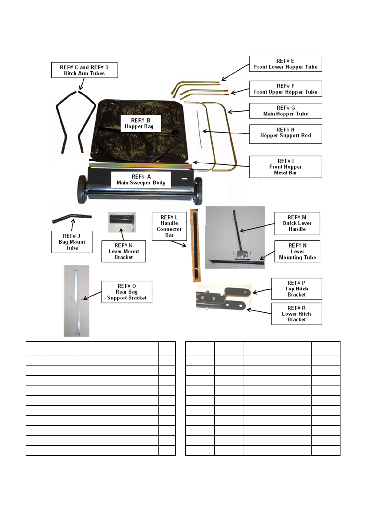
CARTON CONTENTS (Main Parts)
REF#
A Main Sweeper Body 1 I 74 Front Hopper Securing Bar 1
B 67 Hopper Bag 1 J 71 Bag Mount Tube 2
C 2 Hitch Arm Tube, Left 1 K A2 Lever Mount Bracket 1
D 8 Hitch Arm Tube, Right 1 L A6 Handle Connector Bar 1
E 76 Front Lower Hopper Tube - Right 1 M A9 Quick Lever Handle 1
E 62 Front Lower Hopper Tube - Left 1 N A1 Lever Mounting Tube 1
F 72 Front Upper Hopper Tube - Right 1 O B4/B5 Rear Bag Support Bracket 1
F 63 Front Upper Hopper Tube - Leftt 1 P 6 Top Hitch Bracket 1
G 66 Main Hopper Tube 2 R 4 Lower Hitch Bracket 1
H 70 Hopper Bag Support Rod 1 68 Rope (not pictured) 1
Part
Listing # Description Qty REF#
Part
Listing # Description Qty
Page of 14
Page 6

6
HARDWARE PARTS LISTING
G1Hex Lock Nut, 13mm
8Y10
Hitch Pin
1H11
Hex Lock Nut,
11mm
14B6Wing Nut (not shown)
1JA15
Flat Washer, Ø8
2ZA7
Flat hex head bolt 12mm x 3/4”
1
HARDWARE PARTS LISTING
Part
REF#
Listing
# Description Qty REF#
A 9 Hex Bolt, 12mm head x 3-1/8“ long 3 M 5 Hitch Spacer 2
B 7 Hex Bolt, 12mm head x 2-1/8“ long 2 N 3 Hair Cotter Pin (Ø3 Thickness) 5
C 20 HexBolt,12mm head x 1-5/8“ long 2 O 22 Hair Cotter Pin (Ø2 Thickness) 4
D 38 HexBolt,10mm head x 1-1/2“ long 10 P 75 Clevis Pin P, Ø9.5 × 7/8“ long 2
E B-2 Carriage Bolt,10mm x 1-1/2” long 2 Q 61 Clevis Pin Q, Ø6 × 1-1/8“ long 4
F 18 Hex Bolt, 12mm head x 7/8“ long 1 R 17 Clevis Pin P, Ø9.5 ×2-3/8“ long 2
F 19-2 Hex Bolt, 10mm head x 7/8“ long 2
Page of 14
Part
Listing # Description Qty
Page 7

7
STEP #1 ATTACH LEVER MOUNTING TUBE (REF#N)
Parts Needed:
Qty 1 – Main Sweeper Body (REF# A)
Qty 1 – Lever Mount Tube (REF# N)
Qty 1 – 12mm head x 7/8” long bolt
Qty 1 – 13mm lock nut
Connect the lever mounting tube to the sweeper
front panel using 12mm x 7/8” bolt and 13mm lock nut.
Attach to lower hole.
See Photo #1
Fully tighten connection.
STEP #2 ATTACH LEVER BRACKET
Parts Needed:
Qty 1 – Lever Mount Bracket (REF # K)
Qty 2 – 12mm head x 1-5/8” long bolt
Qty 2 – 13mm lock nut
Attach lever bracket to front tube of
main sweeper body using
12mm x 1-5/8” bolt and 13mm lock nut.
See Photo #2
Fully tighten connections.
STEP #3 ATTACH HITCH TUBES
Parts Needed:
Qty 1 – Hitch Arm Tube Right (REF# C)
Qty 1 – Hitch Arm Tube Left (REF #D)
Qty 4 – 10mm head x 1-1/2” long bolt
Qty 4 – 11mm lock nut
Attach hitch arm tubes to the main
sweeper body using 10mm x 1-1/2” bolts
and 11mm lock nut. TIP: moving side
sweeper panel helps align holes.
Repeat for opposite side.
Page of 14
Page 8

8
See Photo #3
STEP #4 CONNECT HITCH TUBES
Parts Needed:
Qty 3 – 12mm head x 3-1/8” long bolts
Qty 3 – 13mm lock nut
Connect hitch arm tubes using
12mm x 3-1/8” bolts and 13mm lock nuts.
Note: connection closest to sweeper body,
connects all 3 tubes. Wait to tighten until hitch
brackets are attached. See Photo #4
Wait to tighten connections.
STEP #5 ATTACH HITCH BRACKETS
Parts Needed:
Qty 1 – Top hitch bracket (REF# P)
Qty 1 – Lower hitch bracket (REF# R)
Qty 2 – 12mm head x 2-1/8” long bolt
Qty 2 – 13mm lock nut
Attach top and lower hitch brackets to
hitch tubes using 12mmx 2-1/8” long bolts
and 13mm lock nuts. Take note the 2 bolts
should insert through tubes around bolt from
previous step. See Photo #5
Tighten all tube connections,
and hitch tubes to sweeper body connections.
Page of 14
Page 9

9
STEP #6 ATTACH QUICK ADJUSTMENT
LEVER HANDLE
Parts Needed:
Qty 1 – Quick Lever Handle Assembly (REF# M)
Qty 2 – 10mm head x 1-1/2” long bolt
Qty 2 – 11mm lock nut
Connect quick lever handle to lever mount
tube using 10mm x 1-1/2” bolts and
11mm lock nuts. Only hand tighten.
Important to wait to tighten connections.
See Photo #6
Wait to tighten connections.
STEP #7 CONNECT QUICK ADJUSTMENT LEVER HANDLE
TO LEVER BRACKET
Parts Needed
Qty 1 – Handle Connector Bar (REF# L)
Qty 1 – Flat head hex head x 3/4” long bolt
Qty 1 – 10mm head x 7/8” long bolt
Qty 2 – 11mm lock nut
Attach handle connector bar to sweeper
body first, hand tighten. Next, you may need
to move sweeper body to align holes of handle
and lever connector bar. Make sure handle base is
positioned as in photo. First, hand
tighten all connections. Then fully tighten.
Be sure to test handle to assure all parts move freely.
See Photo #7
Tighten connections.
Page of 14
Page 10

10
ASSEMBLING THE SWEEPER BAG
STEP #8 INSERT MAIN HOPPER TUBE – TOP SIDE
Parts Needed:
Qty 1 – Main Hopper Bag (REF#B)
Qty 1 – Main Hopper Tube (REF#G)
Insert one main hopper tube
through loops in top of hopper
bag. See Photo #8
STEP #9 ATTACH UPPER HOPPER TUBES to MAIN HOPPER TUBE – TOP SIDE
Parts Needed:
Qty 2 – UPPER Hopper Tubes (REF# F)
Qty 2 – 10mm x 1-1/2” long bolt
Qty 2 – 11mm lock nut
Connect upper hopper tube to main top hopper
tube using 10mm x 1-1/2” bolts and 11mm lock nut.
Do not over tighten.
See Photo #9
STEP #10 ATTACH LOWER HOPPER TUBES to MAIN HOPPER TUBE –
BOTTOM SIDE
Parts Needed:
Qty 2 – LOWER Hopper Tubes (REF# E)
Qty 2 – Washers
Qty 2 – 10mm x 1-1/2” long bolt
Qty 2 – 11mm lock nut
Connect 2 LOWER hopper tubes to
main top hopper tube. IMPORTANTWAIT TO
USE NUTAND BOLT. First slide assembly into bottom
of hopper bag, THEN use washer and bolt, insert bolt
from bottom of bag through assembled tubes
tighten with 11mm lock nut. See Photo #10
Page of 14
Page 11

11
STEP #11 ATTACH REAR SUPPORT BRACKET
Parts Needed:
Qty 1 – Rear Support Bracket assembly (REF# O)
Qty 2 – Carriage bolt 10mm x 1-1/2” long bolt
Qty 2 – 11mm lock nut
Qty 1 – 10mm x 7/8” long bolt (for wing nut)
Qty 1 – Wing Nut
Connect rear support bracket assembly to top
and bottom main hopper tubes using
10mm x 1-1/2” bolt and 11mm lock nut.
See Photo #11
STEP #12 CONNECT UPPER & LOWER TUBES
Parts Needed:
Qty 2: Clevis Pin (Hardware REF# P)
Qty 2: Cotter Pin (Hardware REF# N)
Connect the ends of the lower side tubes
to the ends of the upper side tubes using two
clevis pins REF#P (7/8” long) inserted from the
inside, and two hair cotter pins REF# N.
STEP #13 INSTALL HOPPER BAG SUPPORT ROD
Parts Needed:
Qty 1 – Hopper Support Rod (REF# H)
Insert hopper support rod through top front of bag,
then insert each end of rod into hopper tubes.
Holes are pre-drilled in hopper tube. The support rod will
have slight bend to hold tight between hopper tubes.
See Photo#12
STEP #14 INSERT SECURING METAL BAR
Parts Needed:
Qty 1 – Front Hopper Metal Bar (REF# I)
Qty 2 – Clevis Pin (Hardware REF#Q)
Qty 2 – Cotter Pin (Hardware REF#O)
Insert the front hopper metal bar REF# I into the stitched sleeve on the front edge of the bag bottom.
Next, connect the metal bar to the lower hopper side tubes with two clevis pins REF#Q and hair cotter
pins REF#O. See Photo#12
Page of 14
Page 12

12
STEP #15 ATTACH BAG MOUNT TUBES
Parts Needed:
Qty 2 – Bag Mount Tubes (REF# J)
Qty 2 – Clevis Pin (Hardware REF# R)
Qty 2 – Cotter Pin (Hardware REF# N)
Important – Note direction of tubes,
bend/angle points down. Connect bag support
tubes to hopper upper tubes using
clevis pin REF# R, and cotter pin REF# N.
Insert clevis pin from outside of bag,
cotter pin should be to inside of bag.
See Photo #15
STEP #16 ATTACH BAG TO SWEEPER
Parts Needed:
Qty 2 – Clevis Pin (Hardware REF# Q)
Qty 2 – Cotter Pin (Hardware REF# O)
Align the ends of the bag mount tubes
with the ends of the sweeper hitch tubes
and fasten with clevis pin REF#Q and
cotter pin REF#O for each side. See Photo
STEP #17 ATTACH ROPE
Tie the rope to open area at the top center
of the hopper bag frame. See photo
Page of 14
Page 13

13
OPERATION
WARNING: AVOID OPERATING ON SIDE HILLS. Operating on side hills may
cause unit to tip over and cause damage to sweeper and towing vehicle.
For best sweeping results, do not tow over 3 to 5 MPH. Use Quick Lever handle to adjust brushes
up and down. For best results operate with brushes slightly above ground.
Hook up to towing lawntractor or ATV. Use hitch spacers to help keep sweeper hitch level to
ground see figure 20 and21 below. ALWAYS try to keep sweeper level.
BRUSH HEIGHT ADJUSTMENT
To adjust your sweeper brushes to the best operating height, loosen the adjustment knob and
push down on the height adjustment lever to raise the brush. Best adjustment is when the brush
setting is 1/2” down into the grass.Always mow the grass to an even height before sweeping.
SWEEPING SPEED
Try a starting speed of approximately 3 m.p.h. (third gear on most tractors). Depending on the
conditions, it may be necessary to adjust the sweeping speed in order to achieve best results.
DUMPING OF SWEEPER
Your sweeper can be dumped easily without getting off of the rider or tractor. Simply pull the rope
forward to dump the hopper. Always empty hopper after each use.
CAUTION: Never attach the hopper rope to any part of your body or clothing! Never
hold onto the rope while towing the sweeper! Attach the rope to the towing vehicleto
keep it away from wheels and rotating parts.
Page of 14
Page 14

14
CAUTION: Keep sweeper away from fire. Excessive heat can damage the brushes and
hopper bag and could cause the bag and its contents to burn.
MAINTENANCE
• Maintain your sweeper. It is recommended that the general condition of any sweeper be
examined before it is used. Keep your sweeper in good repair by adopting a program of
conscientious repair and maintenance. If any abnormal vibrations or noise occurs, havethe
problem corrected before further use. Have necessary repairs made by qualified service
personnel.
For replacement parts and technical questions, please call 1-952-938-5222.
WARRANTY
One-year limited warranty
TG
PO BOX 202
Hopkins, MN 55343
Made in Taiwan
Page of 14
 Loading...