


Model/ Modell SA900
ROBOTIC MOWER
RASENROBOTER
Germany Hotline: 0049 2154 8253 0005
Austria Hotline: 0043 12530223115
Mail: yardforce@service-ses.de
Homepage: http://www.service-ses.de
Hotline Deutschland: 0049 2154 8253 0005
Hotline Österreich: 0043 12530223115
Mail: yardforce@service-ses.de
Homepage: http://www.service-ses.de

Read this manual carefully prior to assembling and operating the Mower. It is dangerous to operate this Product without being familiar with these instructions. Keep this manual in a safe place and have it ready for future reference.
2

SA900 Original Instruction
TABLE OF CONTENTS
Packaging Contents |
2 |
|
|
Technical Data |
3 |
|
|
Safety Instruction |
4 |
|
|
Understanding The Robotic Mower |
12 |
|
|
Installation Guide |
18 |
|
|
Programming |
33 |
|
|
Rain Sensor |
45 |
|
|
Charging Information |
46 |
|
|
Maintenance |
47 |
|
|
Troubleshooting |
52 |
|
|
Hot Key List |
56 |
|
|
Declaration Of Conformity |
57 |
1

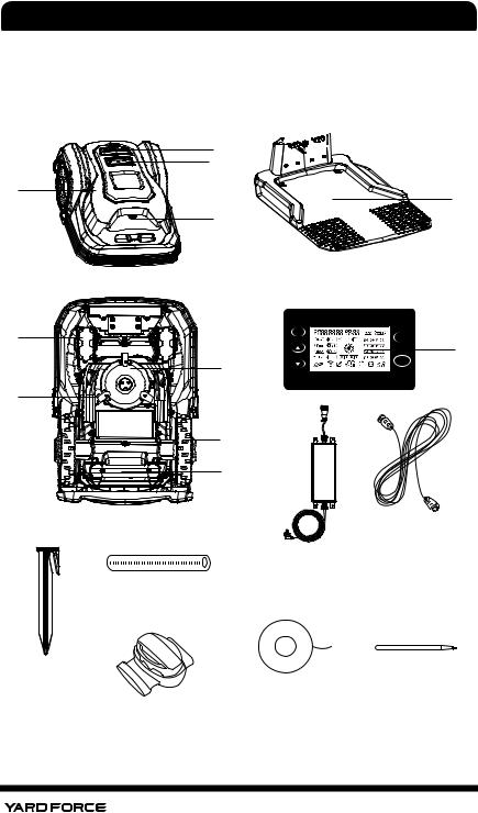
PACKAGING CONTENTS
1. Packaging Contents and Technical Data
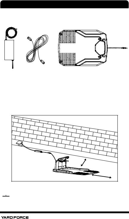
1.1. Packaging Contents
Robot Mower |
Charging Station |
Transformer |
Power Cord |
Boundary Wire |
Fixing Pegs |
Spare blades |
Boundary Wire |
Connector B |
|
||
|
|
|
|
(blue) |
|
|
|
Operating Manual
Manual |
Distance Ruler |
Pen for touch |
screen |
2

TECHNICAL DATA |
||
1.2. Technical Data |
|
|
|
|
|
Model Number |
SA900 |
|
Max Cutting Area |
900 m2 |
|
Electrical Power System |
|
|
Battery |
Lithium-Ion Battery, 25.2 V/2.9 Ah |
|
Power supply |
Input 100-240V AC, 50/60 Hz, |
|
Output 32 VDC, CC1.5A(IP67) |
||
|
||
Typical mow time on one charge |
60 min |
|
Cutting System |
|
|
Rated voltage |
24 VDC |
|
Rated power |
50 W |
|
No load cutting speed |
3500 RPM |
|
Cutting width |
180 mm |
|
Replacement cutting blade |
Part No 846210 |
|
Cutting height, min-max |
20 mm-60 mm |
|
Cutting height number |
5 Settings |
|
Blade number |
Three (Pivoting) |
|
Charging System |
|
|
Charging current |
1.5 A |
|
Charging time |
100 min |
|
Recommended Time Per Day (Hour) |
Note 1 |
|
300 m2 |
2hours |
|
600 m2 |
5hours |
|
900 m2 |
8 hours |
|
General Data |
|
|
|
|
|
Mower Protection |
IP 24 |
|
Charging Station Protection |
IP 24 |
|
Power Supply |
IP 67 |
|
Mower Weight |
8.5 Kg |
|
Charging Station Weight |
1.82 Kg |
|
Mower Size, L x W x H |
570 X 390 X 260 mm |
|
Package Size, L x W x H |
780 X 510 X 330 mm (Ref.) |
|
Gross Weight |
18.5 kg |
|
Noise |
|
|
A Sound Pressure |
46.6 dB |
|
A Sound Power |
LWA= 67 dB (k=0.35 dB) |
|
The recommended time per day stated in this specification is just for reference. It depends on the condition of blades, the type of the grass being cut, the growth condition, humidity, and whether lawn area is flat. This Robotic Lawnmower could work for fewer hours per day than stated if the garden is more complex with trees, flower beds, paths and slopes.
3

SAFETY INSTRUCTION
2. Safety Instruction
IMPORTANT
Read all safety warnings and all instructions.
Failure to follow the warnings and instructions may result in electric shock, fire and /or serious injury. Carefully read the instructions for the safe operation of the machine. Save all warnings and instructions for future reference.
The mower is to be used only for mowing the lawn in yard. Any other use is deemed to be case of misuse.
2.1. Safe Operating Practice
2.1.1. Training
1.Read the instructions carefully, make sure you understand them fully. Be familiar with the controls and the proper use of the machine.
2.Never allow children, persons with reduced physical, sensory or mental capabilities or lack of experience and knowledge or people unfamiliar with these instructions to use the machine, local regulations may restrict the age of the operator
3.Local regulations may restrict the age of the operator.
4.The operator or user is responsible for accidents or hazards occurring to other people or their property.
2.1.2. Preparation
1.Ensure the correct installation of the perimeter boundary system as instructed.
2.Periodically inspect the area where the machine is to be used and remove all stones, sticks, wires,
4

SAFETY INSTRUCTION
and other debris which could cause damage to the machine or be unsafe.
3.Periodically visually inspect to see that the blades, blade bolts and cutter assembly are not worn or damaged. Replace worn or damaged blades and bolts in sets to preserve balance.
4.On multi-spindle machines, take care as rotating one blade can cause other blades to rotate.
2.1.3. Operation
2.1.3.1. General
1.Never operate the machine with defective guards, or without safety devices,for example deflectors and/or grass catchers ,in place.
2.Do not put hands or feet near or under rotating parts.
3.Never pick up or carry a machine while the motor is running.
4.Turn OFF / Powered OFF the machine
–before clearing any blockage.
–before checking, cleaning or maintaining the machine.
5.Start Robotic Mower according to the instructions. When the mains switch is in the ON position, make sure you keep your hands and feet away from the rotating blades.
6.Never lift the Robotic Mower or carry it around with the mains switch is in the ON position.
7.Do not let persons who do not know how the Robotic Mower works and behave use the mower.
8.Do not put anything on top of the Robotic Mower or its charging station
9.Do not use the Robotic Mower with defective
5

SAFETY INSTRUCTION
blade disc, body, defective blades, screws ,nuts etc.
10.Avoid operating the machine in wet grass, if possible. (requires more cleaning).
2.1.3.2. Additionally
When the machine is operating automatically,do not leave the machine to operate unattended if you know that there are pets, children or people in the vicinity.
2.1.3.3. Maintenance and storage
1.Ensure all nuts, bolts and screws are tight to be sure the machine is in safe working condition.
2.Replace worn or damaged parts for safety.
3.Ensure that only the recommended replacement cutting blades are used.
4.Ensure that batteries are charged using the charger supplied or recommended by the manufacturer. Incorrect use may result in electric shock or overheating.
5.Servicing of the machine should be carried out according to manufacturer's instructions.
6.Keep the machine and wheels clean to avoid unbalance and get better cutting performance.
2.2.Safety Symbols
WARNING - Read user instructions before operating the machine.
The supplied robotic lawn mower can be
dangerous if incorrectly used.
Read through the Operator’s manual carefully and understand the content before use.
6

SAFETY INSTRUCTION
WARNING - Keep a safe distance from the
 machine during operation.
Keep your hands and feet away from the rotating blades. Never place your hands or feet close to or under the body when Robotic Mower is in operation.
WARNING – Operate the disabling device before working on or lifting the machine.
Ensure this Switch button is in “OFF” position
before carrying out any Inspection and/or
 maintenance.
WARNING - Do not ride on the machine. CAUTION - Do not touch rotating blade.
WARNING – Remove the disabling device before working on or lifting the machine
Return any discarded batteries to your local dealer , collector or recycle point.
It is not permitted to dispose of this product as Normal household waste when it has reached
the end of its useful life. Please recycle where facilities exist. Check with your Local Authority or retailer for recycling advice.
67 Guaranteed sound power level value in 67 dB
7

SAFETY INSTRUCTION
Warning Symbols on the charger
Warning !
Before any use, refer to the corresponding paragraph in the present manual.
Double insulation.
 Pole orientation
CE conformity mark
Warning Symbols on the battery pack
Batteries contain Li-ion, waste batteries should be sorted for eco-friendly. Do not dispose of waste batteries as unsorted municipal waste. Do not dispose of waste batteries as unsorted municipal waste
 Do not throw into water
 Do not litter to fire.
Do not subject the battery to strong sunlight  over long periods and do not leave it on a heater


 (max.45OC).
8
SAFETY INSTRUCTION
Take batteries to an old battery collection point where they will be recycled in an environmentally friendly manner.
Waste electrical products should not be disposed of with household waste. Please recycle where facilities exist. Check your Local Authority or retailer for recycling advice.
2.3. Additional safety instructions for YARD FORCE Robotic Lawnmower
Do not store anything heavy on the top of Mower or charging station either during storage or in use.
If the main Isolated switch is damaged or does not operate, do not use the robotic lawnmower, never by pass this main switch and always turn to “off” position before storing or when mower is not in use.
It is recommended to re-use the original packaging when transporting the Robotic lawnmower especially for long distances.
If the Robotic Lawnmower ever needs to be moved from or within the working area, first press the large button here to stop it.
9

SAFETY INSTRUCTION
Secondly, ensure that the Main power Isolation switch is selected to OFF position before you lift up your Robotic Lawnmower.
Main Power isolation switch
Engaged switch means power is “ON” and release switch means Power is OFF.
Thirdly, close the top cover, and carry the robotic lawnmower by the handle at the rear under the mower keeping the blade disc away from your body as shown.
10

SAFETY INSTRUCTION
The handle |
position |
2.4. Lightning Protection
In order to prevent lightning cause damage to the machine, please don't place charging station under the tall trees.
In order to prevent lightning causing damage to the machine, please don't place extended cable around the tall trees.
11
UNDERSTANDING THE ROBOTIC MOWER
3. Understanding the YARD FORCE Robotic Mower
Thank you for purchasing the YARD FORCE Robotic Lawnmower,. Over the next few pages, the robotic lawn mower will be explained in further detail considering operation procedure.
2 


 4
4
|
3 |
1 |
5 |
|
|
|
16 |
8 |
Set |
Home |
12
7
6


 9 11
9 11 

10
Start
13 |
14 |
17
15 |
19 |
20 |
18
12

UNDERSTANDING THE ROBOTIC MOWER
3.1. Parts List
1. |
Robotic Lawnmower |
11. |
Main isolation switch |
2. |
Stop button |
12. |
Display screen |
3. |
Display and keypad |
13. |
Transformer |
4. |
Charging contacts |
14. |
Extend cable |
5. |
Charge station |
15. |
Fixing peg |
6. Blade (3per) |
16. |
Rain sensor |
|
7. |
Blade holder |
17. |
Measurement ruler |
8. |
Front wheel |
18. |
Boundary wire connector |
9. |
Rear wheel |
19. |
Boundary wire |
10. Carrying Handle |
20. |
Pen for touch screen |
|
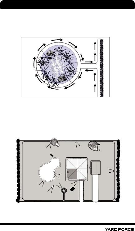
3.2. YARD FORCE Robotic Mower Basic Operating Principles
The Robotic Lawnmower chooses its direction randomly, which means it will mow your garden completely without leaving behind any uncut part within the area restricted by the chosen boundary.
This boundary is chosen by you through installing supplied Boundary wire. Once the YARD FORCE Robotic Lawnmower detect the boundary wire, it will stop, move backwards, and turn away to cut within a different direction. It is important to ensure that the boundary is complete. Any objects you wish to protect within the boundary, such as Garden Pond, Tree, garden furniture or Flower bed can also be protected by the boundary wire. The Boundary wire must form one complete circuit loop. If the Lawnmower during cutting encounters an obstacle, such as a person, tree, pet or general garden obstacles it will stop, move backwards and turn to mow in another direction.
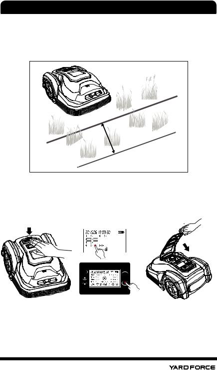
If you have a corridor inside your lawn boundary, the corridor should be at least 2 meters wide and a max length of 8 m.
13

UNDERSTANDING THE ROBOTIC MOWER
min. 2 m
max. 8 m
Note: If your YARD FORCE Robotic Lawnmower lifts while hitting an obstacle, the blade disc stops immediately to avoid any potential damage.
3.2.1. Locating the charging station
After approximately 60 min cutting, when your lawnmower battery voltage is low (depending on the kind of grass that is cut and garden complexity), YARD FORCE Robotic Lawnmower will automatically return to the Charging station by locating the closest boundary wire and follow it anticlockwise (without cutting) back to the charging station for a full recharge and when completed robot will start again with next cutting sequence.
14
UNDERSTANDING THE ROBOTIC MOWER
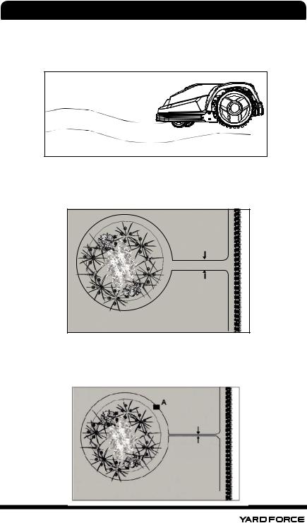
3.2.2. Recognizing the boundary wire
When the YARD FORCE Robotic Mower approaches any boundary wire, the sensor which are installed in front part of the cover will detect it, but before stopping and turning around, the Lawnmower will overrun the boundary by approximately 20 to 30 cm, so please use this information when you create the layout of your boundary (see later).
20 30 cm |
3.2.3. Starting and stopping while mowing
If you want to stop the YARD FORCE Robotic Lawnmower at any time during cutting, please press the STOP button. Once the STOP button is pressed, the Lawnmower will open its keypad top cover, and wait for your further commands. The lawn mower will not start to work until you have closed the top cover.
Set
Home
Start
15

UNDERSTANDING THE ROBOTIC MOWER
3.2.4. YARD FORCE Robotic Mower Mowing Limitations
The YARD FORCE robotic lawnmower is programmed by manufacturer to cut 24 hours, 7 days a week but as every garden will be different and if you want to change these settings, it is easy to program this by yourself see instructions which listed at follow chapter.
If your neighbor is using a YARD FORCE Robotic Lawnmower also, you need keep a 0.5 m distance between your and neighbor’s boundary wires to eliminate interference. And you need keep your charging station more than 10m from your neighbor’s boundary wires, and you have to set a different boundary signal from neighbor's as signal S1 or S2. Ref. 5.5.3 “Signal setting”.
Below is a table showing the signal distances for each of the Robot Mowers, please note your model and use this information as your guide when designing the boundary layout.
Model |
Max field |
Distance of receive the signal |
|
L |
|||
|
|
||
SA900 |
900 m2 |
15 m |
NOTE ! When the working area is less than 100 m2 or total boundary wire less than 40
m, please connect a 20 Ω / 2 W cement resistance to the boundary wire, or contact the service.
3.2.5. YARD FORCE Robotic Mower Cutting Information
The YARD FORCE Robotic Lawnmower has 5 cut height settings between 20mm to 60mm. If the grass height is higher than 60cm, you need cut this grass down to at least 60mm, otherwise the load on the unit will be too large and the cutting efficiency will suffer. Use a normal lawn mower or a grass trimmer. Once the installation is completed, the cut can be adjusted to one of the 5 settings of your choice. Always start in a high cutting position and work yourself down to the cutting height you want. This is carried out by lifting the lid shown and adjusting the large rotating dial here. Note do not attempt to raise or lower the cut height during cutting and always.
16

UNDERSTANDING THE ROBOTIC MOWER
The YARD FORCE Robotic Lawnmower can cut wet grass but wet grass will accumulate on the blade disc and wheels which means more frequent cleaning of unit.
Do not use the YARD FORCE Robotic Lawnmower during lightning or thunder storms in case of damage to the electronic circuitry, it is recommended to unplug the charging station, and disconnect the boundary wire also if possible.
The YARD FORCE Robotic Lawnmower cutting efficiency relies on sharp blades, so please keep them in good condition.
17

INSTALLATION GUIDE
4. Installation Guide
This chapter explains how to install the YARD FORCE Robotic Lawnmower, please read this completely before you start the installation.
4.1. Introduction
It is recommended that you make a draft of your lawn, including all obstacles and how these should be protected. It makes it easier to find a good position for charging station and how to correctly place the boundary wire around your garden perimeter protecting bushes, flower beds etc. You will also need some tools, like a hammer and wire cutters pliers or scissors.
4.2. Cutting Limitations
For rigid and fixed Obstacles higher than 100mm, such as walls, fences garden furniture etc. the crash sensors reacts immediately YARD FORCE Robotic Lawnmower will STOP, reverse backwards and then turn around to cut in another direction but it is still recommendable to protect the obstacle by creating a boundary around these.
< 400 mm |
> 100 mm |
18 |
INSTALLATION GUIDE
Trees
The YARD FORCE Robotic Lawnmower treats trees as common obstacles, but if some roots of the tree are exposed in your garden and lower than 100mm, this area should be protected in order to prevent tree root, cutting blades or rear wheels profile damage.
Stones
If there is rocks or stones situated within the cutting area, this is also an obstacle and needs to be protected as the robotic mower could ride upwards on.
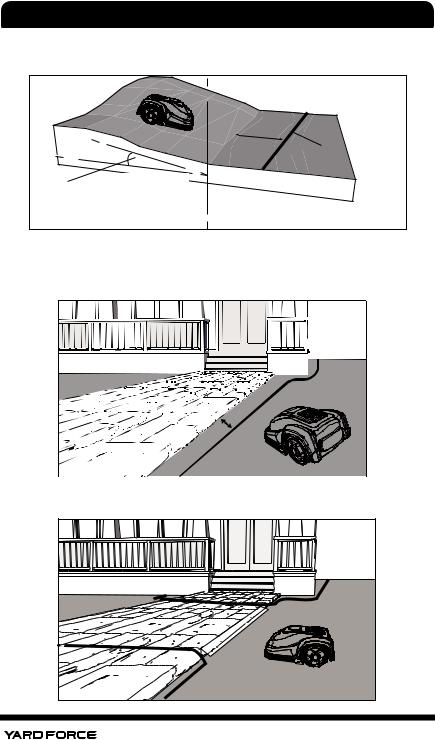
Slopes |
The YARD FORCE Robotic Lawnmower is able to climb uphill and downhill up to a maximum of 40% incline or decline within the cutting area however it is advisable if there is a decline directly towards a boundary wire then this slope should be less than 10 degrees to prevent the Mower from overrunning and pass the boundary wire due to robotic mower downhill running speed, especially if raining or cutting in wet slippery conditions.
Slope should not
be steeper than 40% (27o)
19
INSTALLATION GUIDE
Boundary wire crossing a slope should not exceed 10 degrees if downhill or a flat area to the boundary behind the sloop 2 meter.
min. 2m |
Boundary wire |
Slope should not be |
steeper than 10° |
Paths, Driveways and Roads
If the lawn boundary is close to a driveway is at a different level as your lawn, you should avoid your robotic lawn mower to run over it to the other lawn. And you need a safety distance of 40cm between the boundary wire and the driveway.
cm 0 4 >
 boundary
If the driveway and lawn are at the same level, then you can let the robotic lawn mower run into the other lawn by passing a corridor created by the boundary wire.
 boundary
 boundary
20
INSTALLATION GUIDE
Uneven lawn surfaces
If the lawn area is very uneven then there is the possibility that blades could touch ground when your YARD FORCE Robotic Lawnmower cuts. If this is possible ensure either to remove this issue by leveling or exclude the area totally with boundary wire.
Flowerbeds
If the Lawn working area includes Flowerbeds, that need to be protected with the boundary wire to be excluded from the working area. If you want the robot to follow the boundary wire around the protected area, the distance between the two parallel boundary wires is more than 10cm.
> 10 cm
Another way, if you want the robot to pass over the two parallel boundary wires. The distance between the two parallel wires should be less than 5 mm. But you need put a obstacle like a stone or a tube on position A .
Note: Position A must have a location of flat area, do not set position at any slope. At the side of inside boudary wire, there should be an area 1X1m flat beside position A.
< 5 mm
21

INSTALLATION GUIDE
Ponds and Pools
If the YARD FORCE Robotic Lawnmower enters into a pond it would have a negative effect to the robotic lawn mower lifetime, so please avoid any ponds by excluding them from the working area by the boundary wire or by adding for additional safety such as a small fence around the pool or pond.
> 10 cm
General Dos and Don’ts
Note ! Boundary wires cannot cross each other.
Ensure the boundary wires never cross each other.
Forbidden cross the boundary wire
If you have created a boundary corridor inside your working area, the corridor should be at least 2 m wide and a max length of 8 m.
If your corridor is narrower than 2m or longer than 8m, you need to carry out your YARD FORCE robotic lawnmower from the corridor. Otherwise you need eliminate this corridor by boundary wire.
Max length of |
the corridor |
is 8m |
Minimum width of |
the corridor is 2m |
22 |
INSTALLATION GUIDE
Examples below show how to arrange the boundary around flower beds or other places you do not want cut, please consider that your bushes and flower beds will change during the different seasons from spring to autumn.
An excluded area that is close to the mowing boundary should be kept enough space considering the variable in different seasons.
4.3. Marking out the Robotic Lawnmower’s working area
Now you have understood the basic principles of how the YARD FORCE Robotic Lawnmower works, next step is to mark out the working area with boundary wire by referring to your garden plan already created. This is a very important part of the installation and therefore care must be taken, failure to mark this out correctly will result in many issues later. This boundary wire must be one continuous loop without any break or crossing, which will complete the circuit when connected to charging station.
23
INSTALLATION GUIDE
Firstly, locate the best position for your charging station, consider the nearest outdoor electricity socket as this needs to be plugged in to mains at all times. Please note the Cable length supplied is 20m.
The charging station item 5 must be placed on a flat surface, at ground level and it can be connected with boundary wire both from front and rear side, meanwhile we need 2m wire straight from front side to make sure the lawnmower can return to charging station smoothly. And also there must be 1m flat space beside the charging station. This will allow the Mower to enter the charging station correctly and enable it to reverse to dock. If possible, locate your charging station in the shade as the battery prefers to be recharged in a cool place.
Note: The charging station area should be flat enough, the pond or footstep is not allowed to exist beside the charging station.
> 1 m |
> 2 m |
 Pay attention to protect cable!
24

INSTALLATION GUIDE
The following positions are not allowed.
Charging base left and right slope should be no more than 5 degree angle.
We recommend to keep 3 meters straight wire ahead leading into the charging station. If your lawn soil is soft and uneven, we suggest to use 0.5*1m plastic net in front of charging base to avoid the rear wheel digging into the soil ahead of.
Once the position of the Charging station is confirmed and mains electrical connection is also can be reached, please do not connect to main power yet. First you need to finish all boundary layout work, and then after that, you can connect to the main power.
25

INSTALLATION GUIDE
 Lightning protection
In order to prevent lightning cause damage to the machine, please don't place charging station under the tall trees.
4.4. Pegging Out the Boundary Wire
Next step is to fix the boundary wire, so locate the boundary wire (item 19), unpack it and locate the free end. Also locate the fixing pegs (item 15) and lay each one on Lawn at approximately the correct distance from lawn edges (40cm) and obstacles. There is a gauge supplied for this (item 17) (Remember to ensure the lawn grass height is maximum of 60mm tall, if not cut it before you start pegging). The boundary wire will be laid on top of the grass there is absolutely no need to dig into the ground. The closer you can lay this boundary wire to the ground level, the safer it will be with no risk of tripping or cutter damage. In a very short time the wire will covered by grass and as the voltage in this wire is only 32V. It is totally safe to human beings and pets.
40 cm |
cm |
80 |
Cutting area
The peg should be knocked into lawn with wire location to boundary outside like shown.
26

INSTALLATION GUIDE
It is recommended to place the pegs at a distance of 80 cm apart approximately, but these can be closer where tight bends are required for accurate cutting, do not fix your pegs permanently when laying out for first time, it is advisable to only partially knock in the pegs with a hammer and ensure the wire location slots are all in same orientation to the outside of boundary.
Once all are in correct position, then the boundary wire can be threaded into the slots on pegs one by one around the working area edge. Please start from the charging station and allow an additional 1m of spare wire before cutting off the wire in case a peg needs moving later. When laying out the wire, and adding the pegs, be sure not to tighten the boundary too hard to prevent wire get damaged. Also remember there should be a 2 to 4 meter straight length of wire in front of the charging station in order to allow the robot successfully to dock into charging station. Please be careful also when installing this wire to prevent kinks etc.
Note! If there are hard surfaces where these pegs cannot be used such as a concrete or garden tiles etc. then a screw and plug may be required. If a screw is used then there must be an insulation washer applied.
If the boundary wire needs to be joined for, only use the connectors provided by manufacturer (Item18).
See below for some further sketches giving more distance guidelines.
The potential location of charging station
The initial point of
boundary
The end point of boundary
1m extra wire for potential adjustment
27

INSTALLATION GUIDE
Leaving about 1meter extra wire, peg the wire along the boundary from the rear side of the charging station with a distance of the pegs of 80cm. When you finish the layout and back to the charging station, leave another 1meter extra wire and then cut it.
Make sure if a square corner is uncounted in your working zone, please do not create a 90deg sharp corner as below, the Mower will turn here anyway and cut this area as it turns, so best leave a 45deg angle in each corner see below.
NO |
OK |
If the boundary wire is required to protect a flower bed or other obstacle within the Working area then please follow this suggestion. The boundary wire should be laid from the main Boundary in a straight line as shown then around the profile of the obstacle and then back to the main boundary again, the gap between the two boundary wires shown should be as close as possible without crossing. The same peg can be used to fix them; the YARD FORCE Robotic Lawnmower will mow freely over the double wire.
If you find you do not have enough Boundary wire left to go around the whole area you wish to protect exclude from cutting or if you need to make some changes later then spare wire can be purchased and it is easy to connect with the provided Boundary wire connectors ( Item 18).
4.5. Prepare the boundary Wire For the Charging Station
After laying the boundary wire you need a decrustation pliers (See below left photo) or scissor to clear the teflon cover of the wire and explode the metal threads for connection to the charging station. A length of 10 - 15 mm metal exploring metal threads are recommended. You may twist the end of the metal threads with your fingers to make it tight for connection.
10 - 15 mm |
28
 Loading...