

Page 1
ROBOTIC MOWER
RASENROBOTER
Model/ Modell SA900
Germany Hotline: 0049 2154 8253 0005
Austria Hotline: 0043 12530223115
Mail: yardforce@service-ses.de
Homepage: http://www.service-ses.de
Hotline Deutschland: 0049 2154 8253 0005
Hotline Österreich: 0043 12530223115
Mail: yardforce@service-ses.de
Homepage: http://www.service-ses.de
1
Page 2

Read this manual carefully prior to assembling and
operating the Mower. It is dangerous to operate this
Product without being familiar with these instructions.
Keep this manual in a safe place and have it ready for
future reference.
2
Page 3

SA900 Original Instruction
TABLE OF CONTENTS
Packaging Contents 2
Technical Data 3
Safety Instruction 4
Understanding The Robotic Mower 12
Installation Guide 18
Programming 33
Rain Sensor 45
Charging Information 46
Maintenance 47
Troubleshooting 52
Hot Key List 56
Declaration Of Conformity 57
1
Page 4
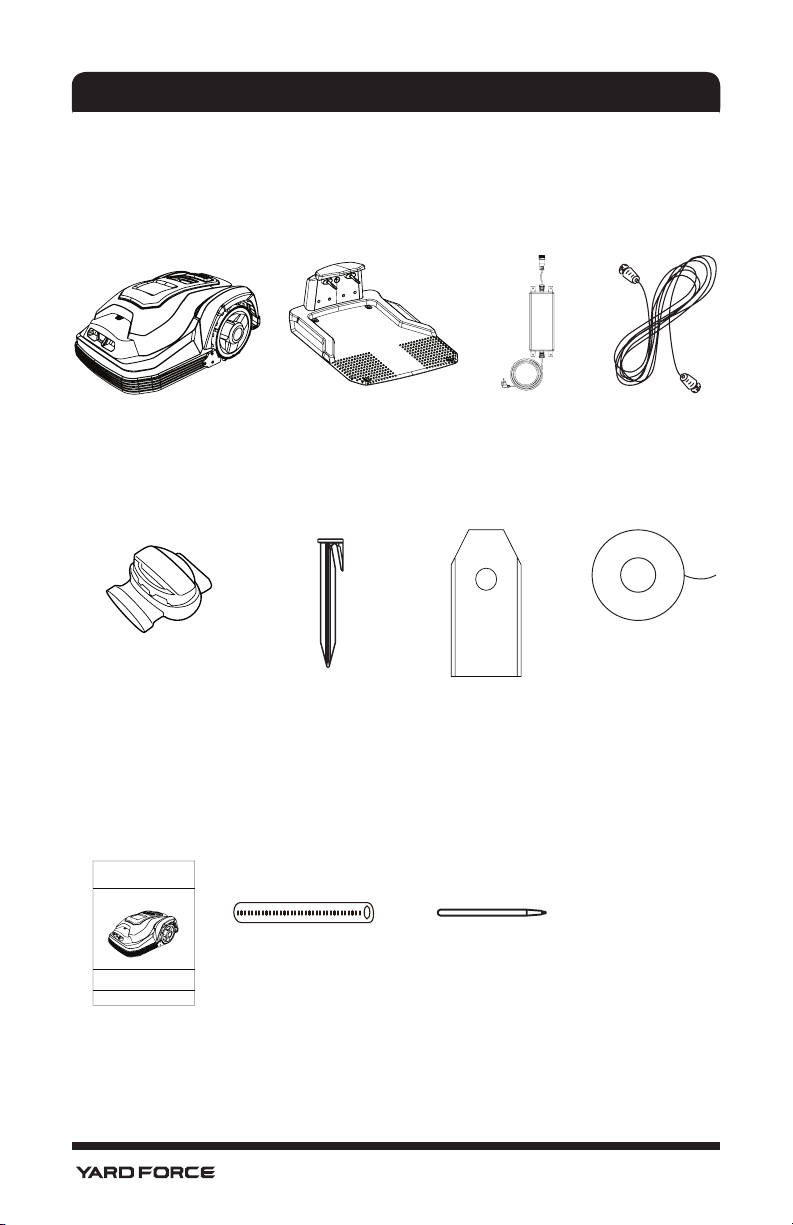
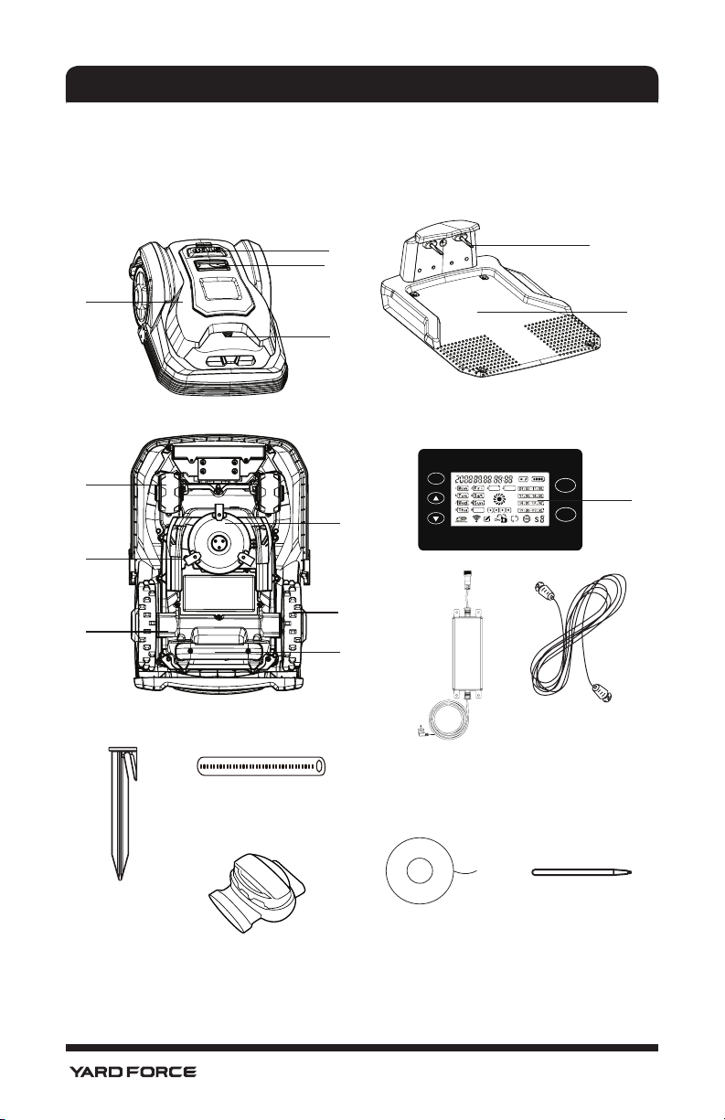
PACKAGING CONTENTS
1. Packaging Contents and Technical Data
1.1. Packaging Contents
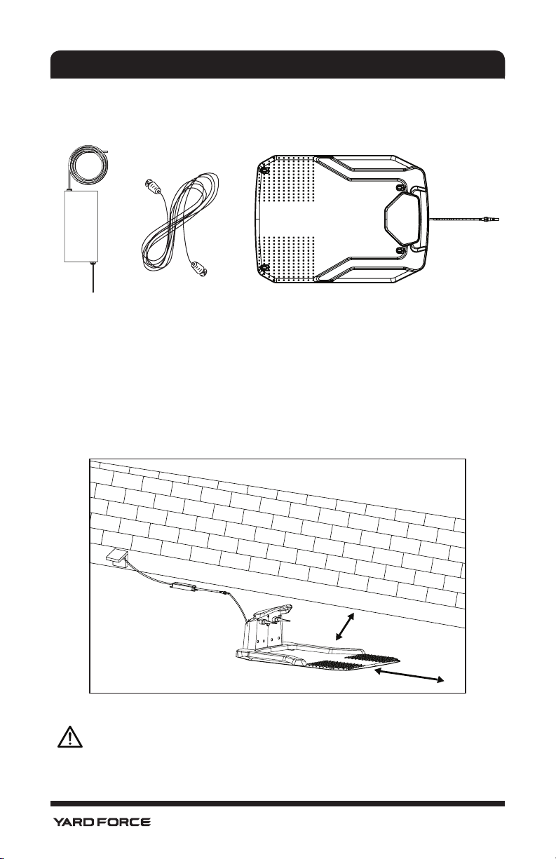
Robot Mower Charging Station Transformer Power Cord
Boundary Wire
Connector B
(blue)
Operating Manual
Manual
Fixing Pegs Spare blades
Distance Ruler
2
Boundary Wire
Pen for touch
screen
Page 5

TECHNICAL DATA
1.2. Technical Data
Model Number SA900
Max Cutting Area 900 m
Electrical Power System
Battery Lithium-Ion Battery, 25.2 V/2.9 Ah
Power supply
Typical mow time on one charge 60 min
Cutting System
Rated voltage 24 VDC
Rated power 50 W
No load cutting speed 3500 RPM
Cutting width 180 mm
Replacement cutting blade Part No 846210
Cutting height, min-max 20 mm-60 mm
Cutting height number 5 Settings
Blade number Three (Pivoting)
Charging System
Charging current 1.5 A
Charging time 100 min
Recommended Time Per Day (Hour) Note 1
2
300 m
2
600 m
2
900 m
General Data
Mower Protection IP 24
Charging Station Protection IP 24
Power Supply IP 67
Mower Weight 8.5 Kg
Charging Station Weight 1.82 Kg
Mower Size, L x W x H 570 X 390 X 260 mm
Package Size, L x W x H 780 X 510 X 330 mm (Ref.)
Gross Weight 18.5 kg
Noise
A Sound Pressure 46.6 dB
A Sound Power L
The recommended time per day stated in this specification is just for reference. It depends
on the condition of blades, the type of the grass being cut, the growth condition, humidity,
and whether lawn area is flat. This Robotic Lawnmower could work for fewer hours per day
than stated if the garden is more complex with trees, flower beds, paths and slopes.
2
Input 100-240V AC, 50/60 Hz,
Output 32 VDC, CC1.5A(IP67)
2hours
5hours
8 hours
= 67 dB (k=0.35 dB)
WA
3
Page 6

SAFETY INSTRUCTION
2. Safety Instruction
IMPORTANT
Read all safety warnings and all instructions.
Failure to follow the warnings and instructions may
result in electric shock, fire and /or serious injury.
Carefully read the instructions for the safe operation
of the machine. Save all warnings and instructions for
future reference.
The mower is to be used only for mowing the lawn
in yard. Any other use is deemed to be case of misuse.
2.1. Safe Operating Practice
2.1.1. Training
1. Read the instructions carefully, make sure you
understand them fully. Be familiar with the controls
and the proper use of the machine.
2. Never allow children, persons with reduced
physical, sensory or mental capabilities or lack of
experience and knowledge or people unfamiliar
with these instructions to use the machine, local
regulations may restrict the age of the operator
3. Local regulations may restrict the age of the
operator.
4. The operator or user is responsible for accidents
or hazards occurring to other people or their
property.
2.1.2. Preparation
1. Ensure the correct installation of the perimeter
boundary system as instructed.
2. Periodically inspect the area where the machine
is to be used and remove all stones, sticks, wires,
4
Page 7

SAFETY INSTRUCTION
and other debris which could cause damage to the
machine or be unsafe.
3. Periodically visually inspect to see that the blades,
blade bolts and cutter assembly are not worn or
damaged. Replace worn or damaged blades and
bolts in sets to preserve balance.
4. On multi-spindle machines, take care as rotating
one blade can cause other blades to rotate.
2.1.3. Operation
2.1.3.1. General
1. Never operate the machine with defective guards,
or without safety devices,for example deflectors
and/or grass catchers ,in place.
2. Do not put hands or feet near or under rotating
parts.
3. Never pick up or carry a machine while the motor
is running.
4. Turn OFF / Powered OFF the machine
– before clearing any blockage.
– before checking, cleaning or maintaining the
machine.
5. Start Robotic Mower according to the instructions.
When the mains switch is in the ON position, make
sure you keep your hands and feet away from the
rotating blades.
6. Never lift the Robotic Mower or carry it around with
the mains switch is in the ON position.
7. Do not let persons who do not know how the
Robotic Mower works and behave use the mower.
8. Do not put anything on top of the Robotic Mower
or its charging station
9. Do not use the Robotic Mower with defective
5
Page 8

SAFETY INSTRUCTION
blade disc, body, defective blades, screws ,nuts
etc.
10. Avoid operating the machine in wet grass, if
possible. (requires more cleaning).
2.1.3.2. Additionally
When the machine is operating automatically,do not
leave the machine to operate unattended if you know
that there are pets, children or people in the vicinity.
2.1.3.3. Maintenance and storage
1. Ensure all nuts, bolts and screws are tight to be sure
the machine is in safe working condition.
2. Replace worn or damaged parts for safety.
3. Ensure that only the recommended replacement
cutting blades are used.
4. Ensure that batteries are charged using the charger
supplied or recommended by the manufacturer.
Incorrect use may result in electric shock or
overheating.
5. Servicing of the machine should be carried out
according to manufacturer's instructions.
6. Keep the machine and wheels clean to avoid
unbalance and get better cutting performance.
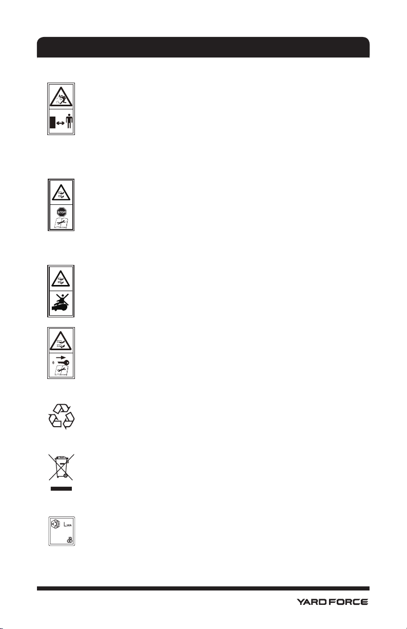
2.2.Safety Symbols
WARNING - Read user instructions before
operating the machine.
The supplied robotic lawn mower can be
dangerous if incorrectly used.
Read through the Operator’s manual carefully
and understand the content before use.
6
Page 9
SAFETY INSTRUCTION
WARNING - Keep a safe distance from the
machine during operation.
Keep your hands and feet away from the
rotating blades. Never place your hands or feet
close to or under the body when Robotic Mower
is in operation.
WARNING – Operate the disabling device
before working on or lifting the machine.
Ensure this Switch button is in “OFF” position
before carrying out any Inspection and/or
maintenance.
WARNING - Do not ride on the machine.
CAUTION - Do not touch rotating blade.
WARNING – Remove the disabling device
before working on or lifting the machine
Return any discarded batteries to your local
dealer , collector or recycle point.
It is not permitted to dispose of this product as
Normal household waste when it has reached
the end of its useful life. Please recycle where
facilities exist. Check with your Local Authority
or retailer for recycling advice.
67
Guaranteed sound power level value in 67 dB
7
Page 10
SAFETY INSTRUCTION
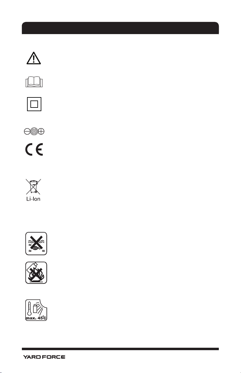
Warning Symbols on the charger
Warning !
Before any use, refer to the corresponding
paragraph in the present manual.
Double insulation.
Pole orientation
CE conformity mark
Warning Symbols on the battery pack
Batteries contain Li-ion, waste batteries should
be sorted for eco-friendly. Do not dispose of
waste batteries as unsorted municipal waste.
Do not dispose of waste batteries as unsorted
municipal waste
Do not throw into water
Do not litter to fire.
Do not subject the battery to strong sunlight
over long periods and do not leave it on a heater
O
(max.45
C).
8
Page 11

SAFETY INSTRUCTION
Take batteries to an old battery collection point
where they will be recycled in an environmentally
friendly manner.
Waste electrical products should not be
disposed of with household waste. Please
recycle where facilities exist. Check your Local
Authority or retailer for recycling advice.
2.3. Additional safety instructions for YARD FORCE
Robotic Lawnmower
Do not store anything heavy on the top of Mower or
charging station either during storage or in use.
If the main Isolated switch is damaged or does not
operate, do not use the robotic lawnmower, never by
pass this main switch and always turn to “off” position
before storing or when mower is not in use.
It is recommended to re-use the original packaging
when transporting the Robotic lawnmower especially
for long distances.
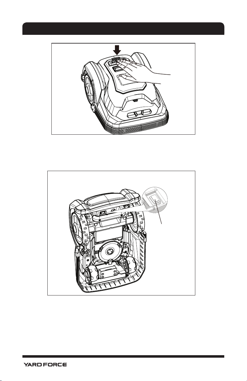
If the Robotic Lawnmower ever needs to be moved
from or within the working area, first press the large
button here to stop it.
9
Page 12
SAFETY INSTRUCTION
Secondly, ensure that the Main power Isolation switch
is selected to OFF position before you lift up your
Robotic Lawnmower.
Main Power
isolation switch
Engaged switch means power is “ON” and release
switch means Power is OFF.
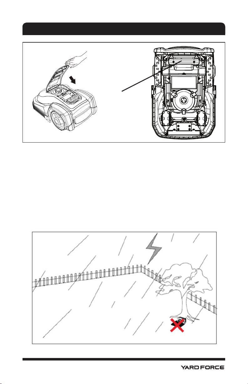
Thirdly, close the top cover, and carry the robotic
lawnmower by the handle at the rear under the mower
keeping the blade disc away from your body as shown.
10
Page 13
SAFETY INSTRUCTION
The handle
position
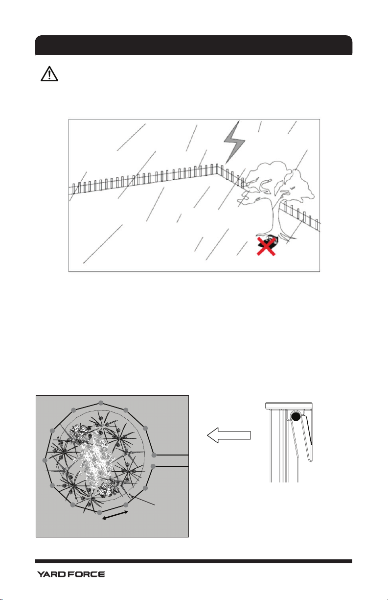
2.4. Lightning Protection
In order to prevent lightning cause damage to the
machine, please don't place charging station under the
tall trees.
In order to prevent lightning causing damage to the
machine, please don't place extended cable around the
tall trees.
11
Page 14
UNDERSTANDING THE ROBOTIC MOWER
3. Understanding the YARD FORCE Robotic Mower
Thank you for purchasing the YARD FORCE Robotic Lawnmower,. Over the next few
pages, the robotic lawn mower will be explained in further detail considering operation
procedure.
2
3
4
1
8
6
11
17
16
9
10
5
Set
7
Home
Start
12
13 14
15
18
12
19
20
Page 15
UNDERSTANDING THE ROBOTIC MOWER
3.1. Parts List
1. Robotic Lawnmower 11. Main isolation switch
2. Stop button 12. Display screen
3. Display and keypad 13. Transformer
4. Charging contacts 14. Extend cable
5. Charge station 15. Fixing peg
6. Blade (3per) 16. Rain sensor
7. Blade holder 17. Measurement ruler
8. Front wheel 18. Boundary wire connector
9. Rear wheel 19. Boundary wire
10. Carrying Handle 20. Pen for touch screen
3.2. YARD FORCE Robotic Mower Basic Operating Principles
The Robotic Lawnmower chooses its direction randomly, which means it will mow your
garden completely without leaving behind any uncut part within the area restricted by the
chosen boundary.
This boundary is chosen by you through installing supplied Boundary wire. Once the YARD
FORCE Robotic Lawnmower detect the boundary wire, it will stop, move backwards, and
turn away to cut within a different direction. It is important to ensure that the boundary is
complete. Any objects you wish to protect within the boundary, such as Garden Pond,
Tree, garden furniture or Flower bed can also be protected by the boundary wire. The
Boundary wire must form one complete circuit loop. If the Lawnmower during cutting
encounters an obstacle, such as a person, tree, pet or general garden obstacles it will
stop, move backwards and turn to mow in another direction.
If you have a corridor inside your lawn boundary, the corridor should be at least 2 meters
wide and a max length of 8 m.
13
Page 16
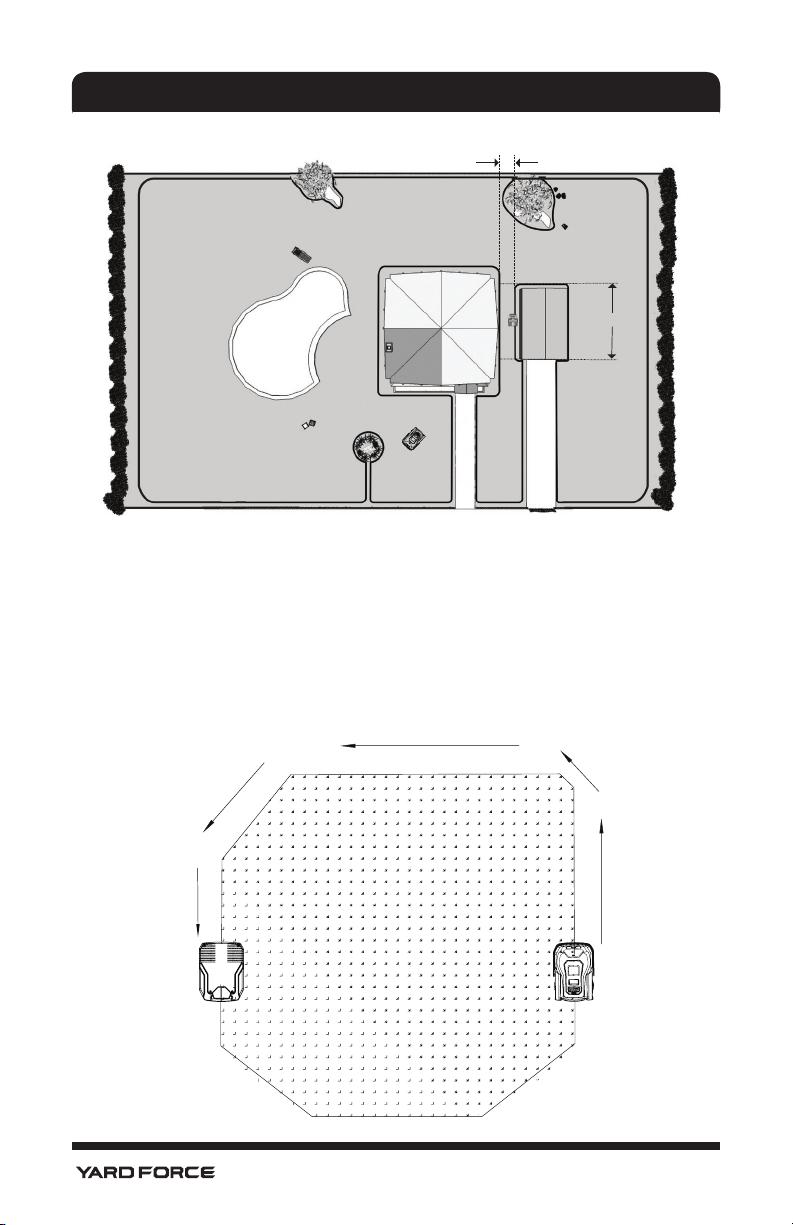
UNDERSTANDING THE ROBOTIC MOWER
min. 2 m
max. 8 m
Note: If your YARD FORCE Robotic Lawnmower lifts while hitting an obstacle, the blade
disc stops immediately to avoid any potential damage.
3.2.1. Locating the charging station
After approximately 60 min cutting, when your lawnmower battery voltage is low
(depending on the kind of grass that is cut and garden complexity), YARD FORCE Robotic
Lawnmower will automatically return to the Charging station by locating the closest
boundary wire and follow it anticlockwise (without cutting) back to the charging station for
a full recharge and when completed robot will start again with next cutting sequence.
14
Page 17
UNDERSTANDING THE ROBOTIC MOWER
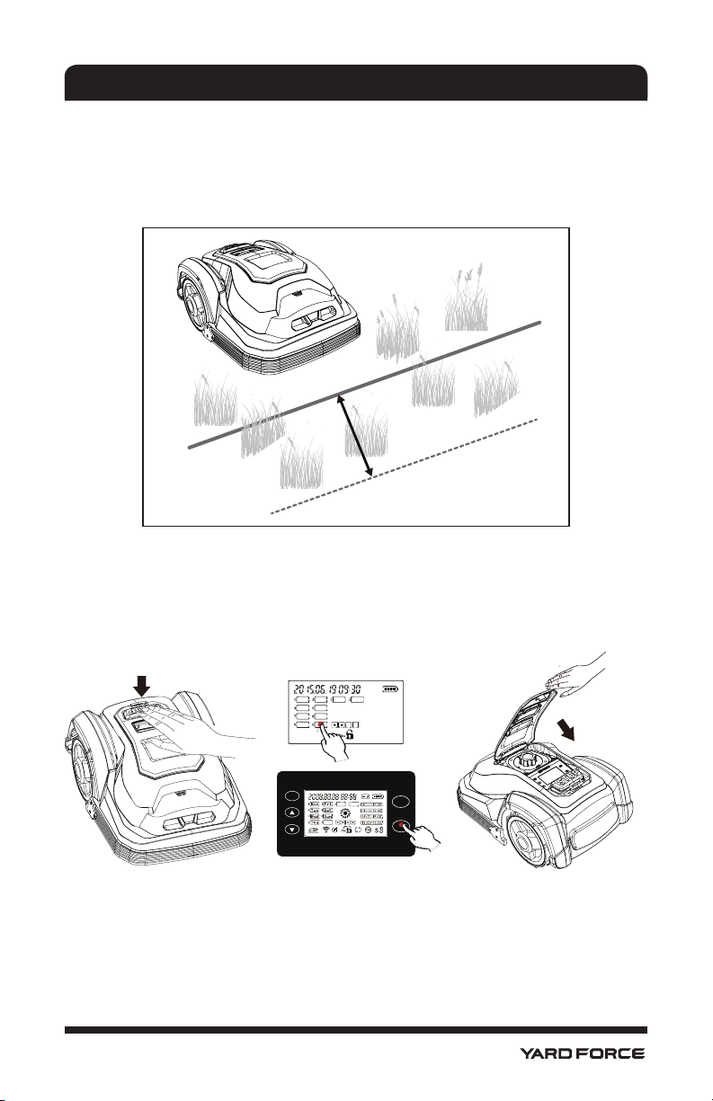
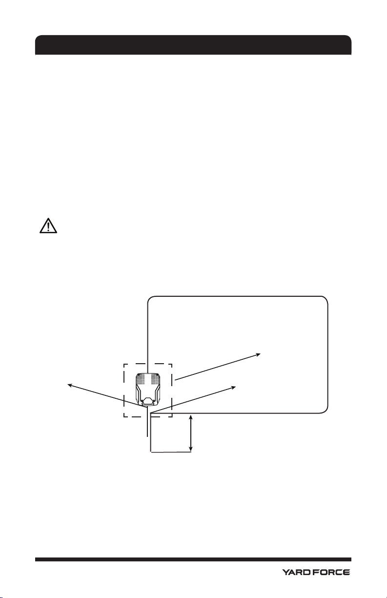
3.2.2. Recognizing the boundary wire
When the YARD FORCE Robotic Mower approaches any boundary wire, the sensor
which are installed in front part of the cover will detect it, but before stopping and turning
around, the Lawnmower will overrun the boundary by approximately 20 to 30 cm, so
please use this information when you create the layout of your boundary (see later).
20-30 cm
3.2.3. Starting and stopping while mowing
If you want to stop the YARD FORCE Robotic Lawnmower at any time during cutting,
please press the STOP button. Once the STOP button is pressed, the Lawnmower will
open its keypad top cover, and wait for your further commands. The lawn mower will not
start to work until you have closed the top cover.
Set
Home
Start
15
Page 18
UNDERSTANDING THE ROBOTIC MOWER
3.2.4. YARD FORCE Robotic Mower Mowing Limitations
The YARD FORCE robotic lawnmower is programmed by manufacturer to cut 24 hours, 7
days a week but as every garden will be different and if you want to change these settings,
it is easy to program this by yourself see instructions which listed at follow chapter.
If your neighbor is using a YARD FORCE Robotic Lawnmower also, you need keep a 0.5 m
distance between your and neighbor’s boundary wires to eliminate interference. And you
need keep your charging station more than 10m from your neighbor’s boundary wires, and
you have to set a different boundary signal from neighbor's as signal S1 or S2. Ref.
“Signal setting”.
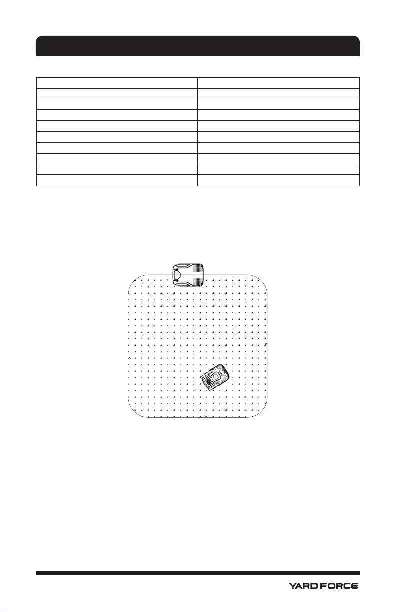
Below is a table showing the signal distances for each of the Robot Mowers, please note
your model and use this information as your guide when designing the boundary layout.
5.5.3
Model Max field
SA900 900 m
When the working area is less than 100 m2 or total boundary wire less than 40
NOTE !
m, please connect a 20 Ω / 2 W cement resistance to the boundary wire, or contact the
service.
2
Distance of receive the signal
L
15 m
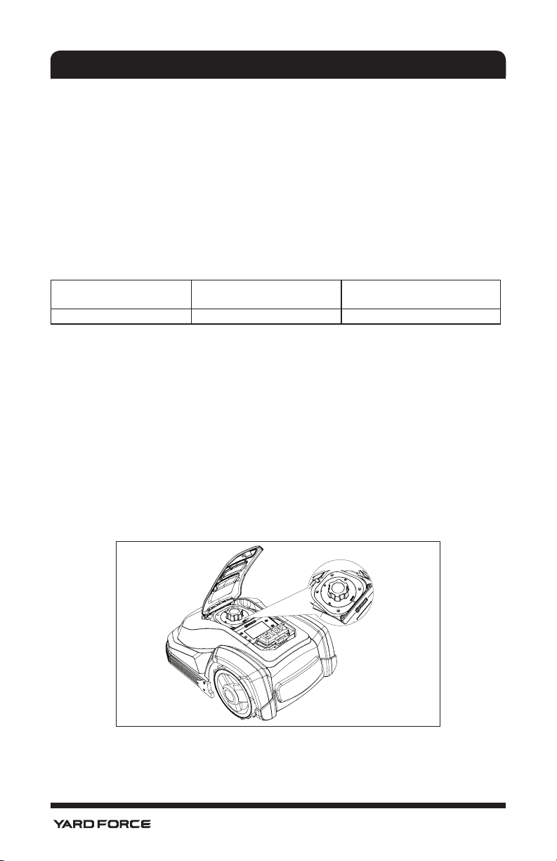
3.2.5. YARD FORCE Robotic Mower Cutting Information
The YARD FORCE Robotic Lawnmower has 5 cut height settings between 20mm to 60mm.
If the grass height is higher than 60cm, you need cut this grass down to at least 60mm,
otherwise the load on the unit will be too large and the cutting efficiency will suffer. Use
a normal lawn mower or a grass trimmer. Once the installation is completed, the cut can
be adjusted to one of the 5 settings of your choice. Always start in a high cutting position
and work yourself down to the cutting height you want. This is carried out by lifting the lid
shown and adjusting the large rotating dial here. Note do not attempt to raise or lower the
cut height during cutting and always.
16
Page 19

UNDERSTANDING THE ROBOTIC MOWER
The YARD FORCE Robotic Lawnmower can cut wet grass but wet grass will accumulate
on the blade disc and wheels which means more frequent cleaning of unit.
Do not use the YARD FORCE Robotic Lawnmower during lightning or thunder storms
in case of damage to the electronic circuitry, it is recommended to unplug the charging
station, and disconnect the boundary wire also if possible.
The YARD FORCE Robotic Lawnmower cutting efficiency relies on sharp blades, so please
keep them in good condition.
17
Page 20
INSTALLATION GUIDE
4. Installation Guide
This chapter explains how to install the YARD FORCE Robotic Lawnmower, please read
this completely before you start the installation.
4.1. Introduction
It is recommended that you make a draft of your lawn, including all obstacles and how
these should be protected. It makes it easier to find a good position for charging station
and how to correctly place the boundary wire around your garden perimeter protecting
bushes, flower beds etc. You will also need some tools, like a hammer and wire cutters
pliers or scissors.
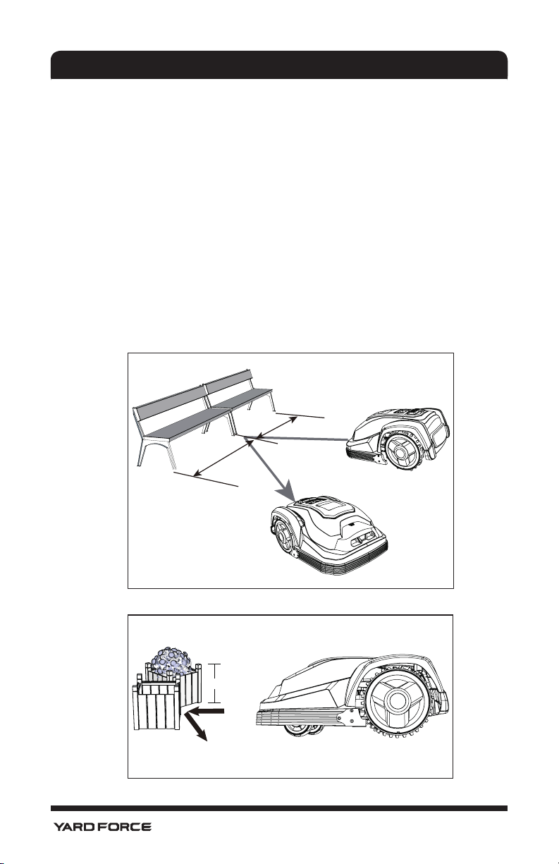
4.2. Cutting Limitations
For rigid and fixed Obstacles higher than 100mm, such as walls, fences garden furniture
etc. the crash sensors reacts immediately YARD FORCE Robotic Lawnmower will
STOP, reverse backwards and then turn around to cut in another direction but it is still
recommendable to protect the obstacle by creating a boundary around these.
< 400 mm
> 100 mm
18
Page 21
INSTALLATION GUIDE
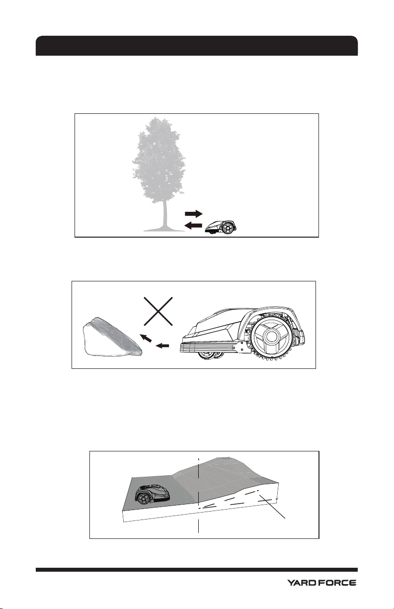
Trees
The YARD FORCE Robotic Lawnmower treats trees as common obstacles, but if some
roots of the tree are exposed in your garden and lower than 100mm, this area should be
protected in order to prevent tree root, cutting blades or rear wheels profile damage.
Stones
If there is rocks or stones situated within the cutting area, this is also an obstacle and
needs to be protected as the robotic mower could ride upwards on.
Slopes
The YARD FORCE Robotic Lawnmower is able to climb uphill and downhill up to a
maximum of 40% incline or decline within the cutting area however it is advisable if there is
a decline directly towards a boundary wire then this slope should be less than 10 degrees
to prevent the Mower from overrunning and pass the boundary wire due to robotic mower
downhill running speed, especially if raining or cutting in wet slippery conditions.
Slope should not
be steeper than 40% (27
o
)
19
Page 22
INSTALLATION GUIDE
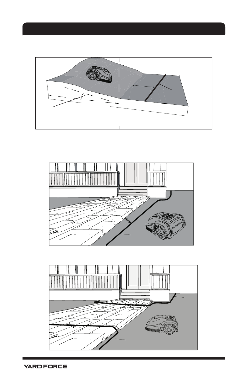
Boundary wire crossing a slope should not exceed 10 degrees if downhill or a flat area to
the boundary behind the sloop 2 meter.
min. 2m
Boundary wire
Slope should not be
steeper than 10°
Paths, Driveways and Roads
If the lawn boundary is close to a driveway is at a different level as your lawn, you should
avoid your robotic lawn mower to run over it to the other lawn. And you need a safety
distance of 40cm between the boundary wire and the driveway.
> 40 cm
boundary
If the driveway and lawn are at the same level, then you can let the robotic lawn mower run
into the other lawn by passing a corridor created by the boundary wire.
boundary
boundary
20
Page 23

INSTALLATION GUIDE
Uneven lawn surfaces
If the lawn area is very uneven then there is the possibility that blades could touch ground
when your YARD FORCE Robotic Lawnmower cuts. If this is possible ensure either to
remove this issue by leveling or exclude the area totally with boundary wire.
Flowerbeds
If the Lawn working area includes Flowerbeds, that need to be protected with the
boundary wire to be excluded from the working area. If you want the robot to follow the
boundary wire around the protected area, the distance between the two parallel boundary
wires is more than 10cm.
> 10 cm
Another way, if you want the robot to pass over the two parallel boundary wires. The
distance between the two parallel wires should be less than 5 mm. But you need put a
obstacle like a stone or a tube on position A .
Note: Position A must have a location of flat area, do not set position at any slope. At the
side of inside boudary wire, there should be an area 1X1m flat beside position A.
< 5 mm
21
Page 24
INSTALLATION GUIDE
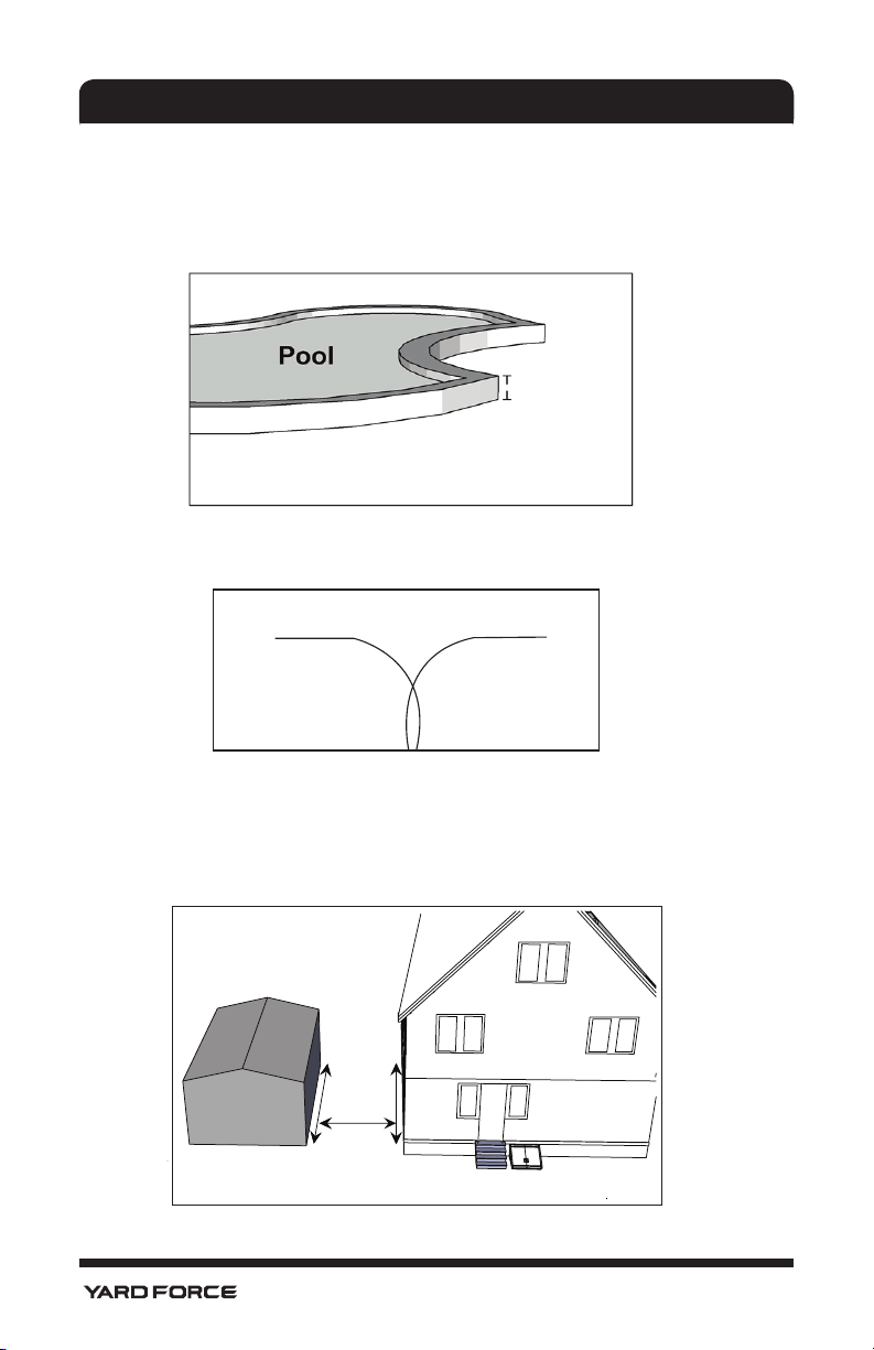
Ponds and Pools
If the YARD FORCE Robotic Lawnmower enters into a pond it would have a negative effect
to the robotic lawn mower lifetime, so please avoid any ponds by excluding them from the
working area by the boundary wire or by adding for additional safety such as a small fence
around the pool or pond.
> 10 cm
General Dos and Don’ts
Note ! Boundary wires cannot cross each other.
Ensure the boundary wires never cross each other.
Forbidden cross the boundary wire
If you have created a boundary corridor inside your working area, the corridor should be at
least 2 m wide and a max length of 8 m.
If your corridor is narrower than 2m or longer than 8m, you need to carry out your YARD
FORCE robotic lawnmower from the corridor. Otherwise you need eliminate this corridor
by boundary wire.
Max length of
the corridor
is 8m
Minimum width of
the corridor is 2m
22
Page 25
INSTALLATION GUIDE
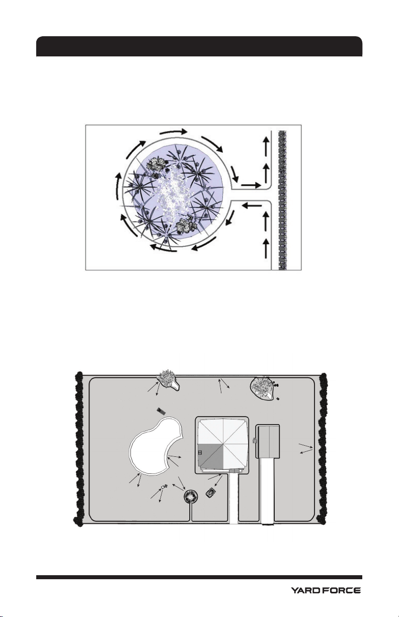
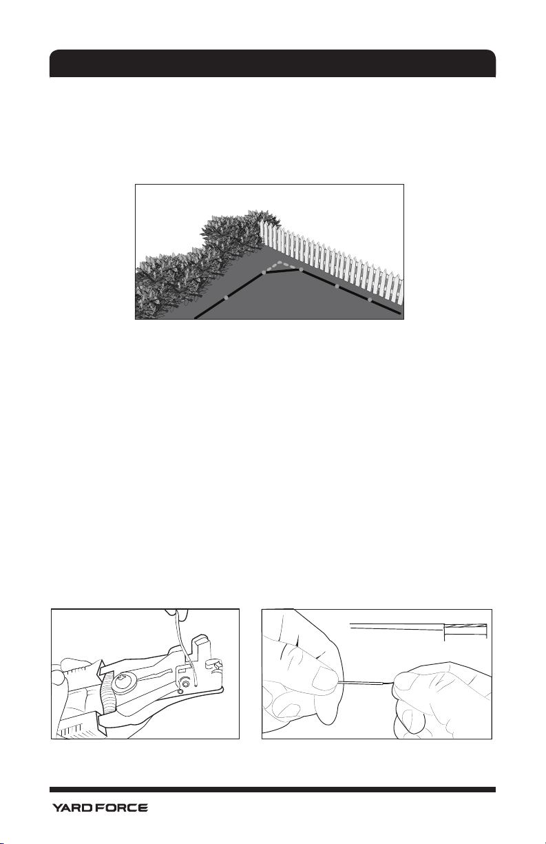
Examples below show how to arrange the boundary around flower beds or other places
you do not want cut, please consider that your bushes and flower beds will change during
the different seasons from spring to autumn.
An excluded area that is close to the mowing boundary should be kept enough space
considering the variable in different seasons.
4.3. Marking out the Robotic Lawnmower’s working area
Now you have understood the basic principles of how the YARD FORCE Robotic
Lawnmower works, next step is to mark out the working area with boundary wire
by referring to your garden plan already created. This is a very important part of the
installation and therefore care must be taken, failure to mark this out correctly will result in
many issues later. This boundary wire must be one continuous loop without any break or
crossing, which will complete the circuit when connected to charging station.
23
Page 26
INSTALLATION GUIDE
Firstly, locate the best position for your charging station, consider the nearest outdoor
electricity socket as this needs to be plugged in to mains at all times. Please note the
Cable length supplied is 20m.
The charging station item 5 must be placed on a flat surface, at ground level and it can
be connected with boundary wire both from front and rear side, meanwhile we need 2m
wire straight from front side to make sure the lawnmower can return to charging station
smoothly. And also there must be 1m flat space beside the charging station. This will
allow the Mower to enter the charging station correctly and enable it to reverse to dock. If
possible, locate your charging station in the shade as the battery prefers to be recharged
in a cool place.
Note: The charging station area should be flat enough, the pond or footstep is not allowed
to exist beside the charging station.
Pay attention to protect cable!
24
> 1 m
> 2 m
Page 27
INSTALLATION GUIDE
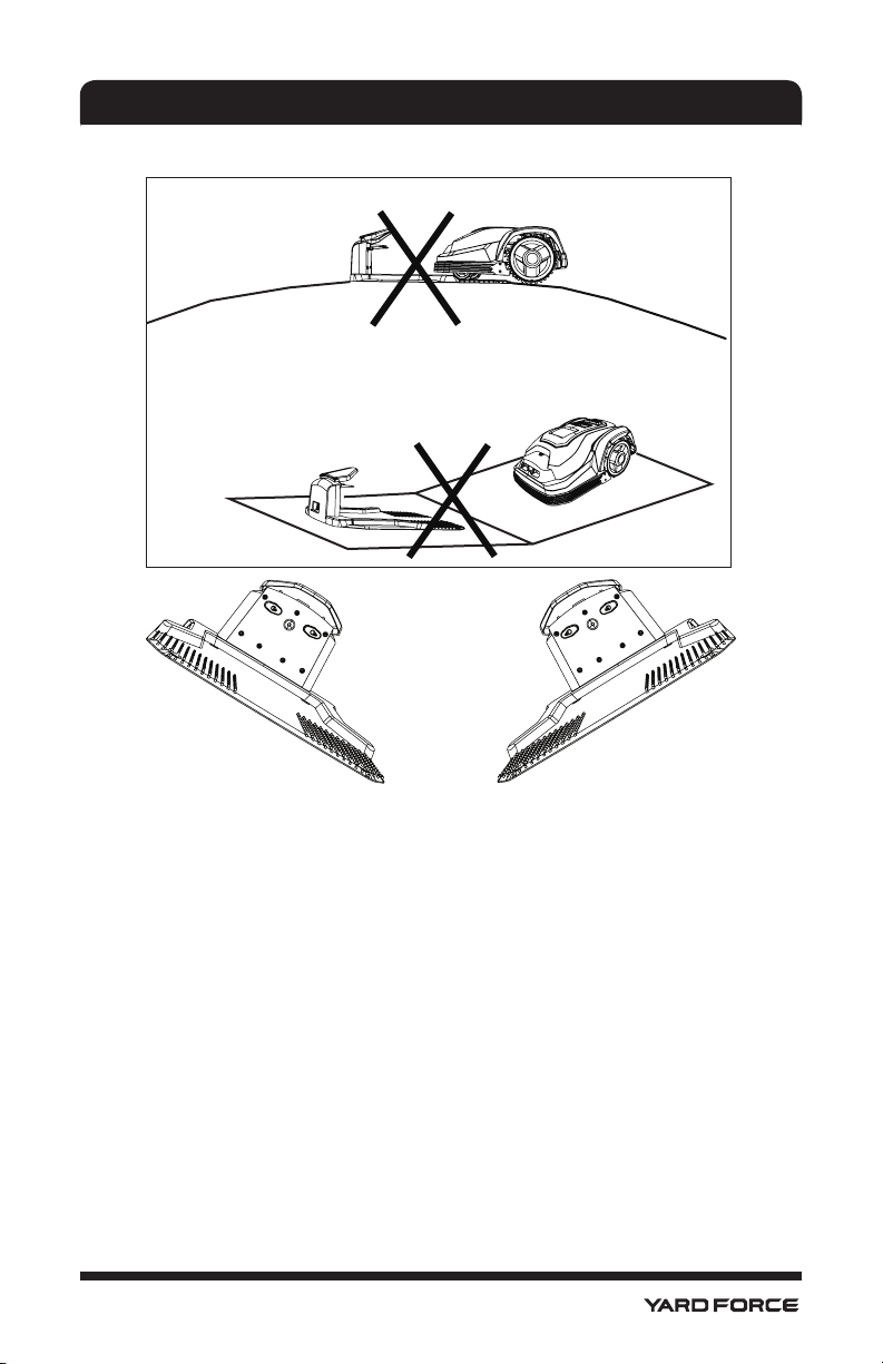
The following positions are not allowed.
Charging base left and right slope should be no more than 5 degree angle.
We recommend to keep 3 meters straight wire ahead leading into the charging station. If
your lawn soil is soft and uneven, we suggest to use 0.5*1m plastic net in front of charging
base to avoid the rear wheel digging into the soil ahead of.
Once the position of the Charging station is confirmed and mains electrical connection is
also can be reached, please do not connect to main power yet. First you need to finish all
boundary layout work, and then after that, you can connect to the main power.
25
Page 28
INSTALLATION GUIDE
Lightning protection
In order to prevent lightning cause damage to the machine, please don't place charging
station under the tall trees.
4.4. Pegging Out the Boundary Wire
Next step is to fix the boundary wire, so locate the boundary wire (item 19), unpack it
and locate the free end. Also locate the fixing pegs (item 15) and lay each one on Lawn
at approximately the correct distance from lawn edges (40cm) and obstacles. There is a
gauge supplied for this (item 17) (Remember to ensure the lawn grass height is maximum
of 60mm tall, if not cut it before you start pegging). The boundary wire will be laid on top
of the grass there is absolutely no need to dig into the ground. The closer you can lay
this boundary wire to the ground level, the safer it will be with no risk of tripping or cutter
damage. In a very short time the wire will covered by grass and as the voltage in this wire
is only 32V. It is totally safe to human beings and pets.
Cutting
area
40 cm
The peg should be knocked into lawn
with wire location to boundary outside
like shown.
80 cm
26
Page 29
INSTALLATION GUIDE
It is recommended to place the pegs at a distance of 80 cm apart approximately, but these
can be closer where tight bends are required for accurate cutting, do not fix your pegs
permanently when laying out for first time, it is advisable to only partially knock in the pegs
with a hammer and ensure the wire location slots are all in same orientation to the outside
of boundary.
Once all are in correct position, then the boundary wire can be threaded into the slots on
pegs one by one around the working area edge. Please start from the charging station
and allow an additional 1m of spare wire before cutting off the wire in case a peg needs
moving later. When laying out the wire, and adding the pegs, be sure not to tighten the
boundary too hard to prevent wire get damaged. Also remember there should be a 2 to
4 meter straight length of wire in front of the charging station in order to allow the robot
successfully to dock into charging station. Please be careful also when installing this wire
to prevent kinks etc.
Note! If there are hard surfaces where these pegs cannot be used such as a
concrete or garden tiles etc. then a screw and plug may be required. If a screw is
used then there must be an insulation washer applied.
If the boundary wire needs to be joined for, only use the connectors provided by
manufacturer (Item18).
See below for some further sketches giving more distance guidelines.
The initial point of
boundary
The potential location of charging station
The end point of boundary
1m extra wire
for potential
adjustment
27
Page 30
INSTALLATION GUIDE
Leaving about 1meter extra wire, peg the wire along the boundary from the rear side of the
charging station with a distance of the pegs of 80cm. When you finish the layout and back
to the charging station, leave another 1meter extra wire and then cut it.
Make sure if a square corner is uncounted in your working zone, please do not create
a 90deg sharp corner as below, the Mower will turn here anyway and cut this area as it
turns, so best leave a 45deg angle in each corner see below.
NO
OK
If the boundary wire is required to protect a flower bed or other obstacle within the Working
area then please follow this suggestion. The boundary wire should be laid from the main
Boundary in a straight line as shown then around the profile of the obstacle and then back
to the main boundary again, the gap between the two boundary wires shown should be
as close as possible without crossing. The same peg can be used to fix them; the YARD
FORCE Robotic Lawnmower will mow freely over the double wire.
If you find you do not have enough Boundary wire left to go around the whole area you
wish to protect exclude from cutting or if you need to make some changes later then
spare wire can be purchased and it is easy to connect with the provided Boundary wire
connectors ( Item 18).
4.5. Prepare the boundary Wire For the Charging Station
After laying the boundary wire you need a decrustation pliers (See below left photo) or
scissor to clear the teflon cover of the wire and explode the metal threads for connection
to the charging station. A length of 10 - 15 mm metal exploring metal threads are
recommended. You may twist the end of the metal threads with your fingers to make it
tight for connection.
10 - 15 mm
28
Page 31

INSTALLATION GUIDE
4.6. Connect the Charging Station With the Boundary Wire
Once connectors have been prepared to each of the two boundary wire ends then these
can be connected to the charging station as shown below. It is important to lay the wire
from the front of the charging station underneath the base to protect it before connecting
at the rear. This connector should then be connected to the Left hand tab marked S1 or
S2, and the rear boundary wire connector is connected to the Right hand tab marked "+".
S2
S1
S1 or S2
S2
S1
IMPORTANT INFORMATION
Double check that the charger connections are as shown below. Even if it is blue light the
connectors are wrongly connected the machine will not work.
NOTE !
m, please connect a 20 Ω / 2 W cement resistance to the boundary wire, or contact the
service.
When the working area is less than 100 m2 or total boundary wire less than 40
After connecting the S1 or S2 and "+" connectors to the charging station, the charging
station can be fixed down with the boundary pegs(item 15). Please ensure before this is
done that the charging station is still situated on a flat surface and mains connection is
still can be reached. Also ensure that 2m of straight boundary wire is in front and to rear
of station and any surplus boundary cable is tucked under the charging station base to
protect it.
Once this is done, Connect the charger extension cable (Item 14) to Charging base,
meanwhile ensuring that the power supply is not connected to mains voltage just yet.
29
Page 32

INSTALLATION GUIDE
Once these connections are made, plug in power supply, there is a blue LED Light on
charging station, see below and if all is ok, it should light up with constant green. If no LED
is lit, check the power connections firstly, if LED is on but not constant green refer to the
trouble shooting guide below.
LED Description
1 Blue light on Normal
2 Blue flash, Red off Charging station internal wire break, main Boundary is OK
3 Red flash, Blue off
4 Red and Blue flash
Boundary cut off or poor connect, charging station internal wire
is OK
Boundary and charging station internal wire both short circuit or
cut off
LED
4.7. Turn On and Test the Installation
Once the LED light is constant green, this means all is ok so now the Boundary wire pegs
can be knocked fully with hammer. Once this is done, double check the light is still blue
if yes then the boundary and charging station are all working as normal. Then place the
YARD FORCE Robotic Lawnmower in the working area, a few meters beside the charging
station.
30
Page 33

INSTALLATION GUIDE
Press the Mower Power isolated switch to “ON”. (Press again for OFF)
See later for further explanation.
Power Isolation
switch status:
OFF (Released)
Power Isolation
switch status:
ON (Pressed)
Now press the large STOP button on top of Mower then the keypad top cover will open.
Press the key Marked HOME (situated to right of display) and then manually press the top
cover to closed position. Once closed the Mower should start and will automatically return
to the Charging station by locating a Boundary wire and following it. The mower should
follow the wire in an anti-clockwise direction and when gets close to the Charging station
and dock into charging position. The mower will start to fully charge. If robot misses to
dock, you might have to adjust the charging station sideways until robot docks without any
problem.
Set
Home
Start
After successfully dock into the charging station, the symbol will ash. Meanwhile,
the battery symbol will display step by step ,
which means that the robot mower is charging now.
31
Page 34

INSTALLATION GUIDE
Once the lawnmower can work normally and the charging station has been found suitable
location, use hammer and knock the pegs fully home to secure the base. Remember any
tucked under wire must not be kinked or damaged, this is very important.
1m outside o f boundary area
need to be flat
Area to be cut
2m
32
Page 35

PROGRAMMING
5. Programming
IMPORTANT
PLEASE SET DATE AND TIME AS THIS IS THE BASE
FOR THE REST OF THE PROGRAMMIN!
5.1. Control Panel
Once this Charging has completed the Mower programming can now be carried out.
To start programming the STOP button must be pressed again which will allow the display
window to open. Then the programming process can be followed.
The Mower has already been programmed in the factory to a set of standard settings but
these can be changed if you want. Even though factory settings will suit the majority of users it is worth familiarizing yourself with options available.
Set
Home
Start
IMPORTANT
THE CENTRE DISPAY AREA IS A TOUCH SCREEN!
Button options:
Choose button: For each press the display
Cursor will move upwards or left,
And will show the different setting options.
Choose button: For each press the display
Cursor will move upwards or Right,
And will show the different setting options.
33
Page 36

PROGRAMMING
Set key: To enable a certain function or start adjust machine setting.
Set
Home
Start
Home key: The YARD FORCE Robotic Lawnmower will go directly to charge
when you press Home button.
Start key: Press the Start button YARD FORCE robotic lawnmower will start
cutting cycle.
5.2. Touch screen overview
Zone 2
Zone 1
Zone 3
Zone 4
The touch screen is a combination of several functional area.
Zone 1: Date area.
Zone 2: Time area. When error occurs, also display error code.
Zone 3: Working day selection area and numerical keyboard for pincode input.
Zone 4: Machine staus display.
Zone 5: Battery and charging status display
Zone 6: Working time display.
Zone 7: Cutting display and pincode input display.
Zone 5
Zone 6
Zone 7
5.3. Status display
5.3.1 Boundary wire signal intensity
The boundary wire is generating a boundary signal, therefore the closer to the boundary
wire the stronger the robot mower will receive.
This symbol means good signal. Robot mower will work normal.
This symbol means weak signal. Robot mower will work normal.
Flashing ! This symbol means “no signal”. In this case robot mower stops cutting.
Flashing ! This means “Outside”.In this case robot mower stops cutting.
34
Page 37

PROGRAMMING
5.3.2 Lift signal
Flashing ! When the robot mower is lifted, this symbol display.
Note! Lift signal could also be generated by a vibration on the robot.
After short time (< 1 second) be lifed, the robot mower will return to work normal. In case
the lift signal last more than 1 sencond and less than 8 seconds, robot will stop and later
restart automatically. In case the lift signal last more than 8 seconds, robot mower will lock
itself automatically for anti-theft and alarms.
5.3.3 Battery and charging
After each charging robot left the charging station with full battery capacity.
This symbol means the battery has a remain capacity of 75%.
This symbol means the battery has a remain capacity of 50%.
This symbol means the battery has a remain capacity of 30%.
This symbol means the battery is empty
(Sustained) Mower is going back to charging station to get charged.
(Flash) Mower is charging on charging station
(Flash) (Sustained) When mower is on charging station, This means is
battery is fully charged and charging nish.
5.3.4 Touch screen and input
Touch screen is locked
Input normally Pincode to unlock touch screen
Input new pincode when you change normally pincode
Input new pincode again when you change normally pincode
5.3.5 Others
You select boundary signal S1
You select boundary signal S2
35
Page 38

PROGRAMMING
STOP Key is pressed , Mower stop to cut
5.4. Security PIN code
After power on the machine, robot are locked with a factory setting PIN code. Please press
the graphic of a lock, then the PIN code input screen will display.
Factory initial setting of the PIN code is “0000”. Press the blank frame of “0” continuously
4 times then the robot will be unlocked. (Black dot will be displayed showing how many
digits has been inputed insead of showing real number). Regular operation interface will
display.
5.5. Setting
5.5.1 Set Date and Time
Set
Home
Start
Press the button of “SET” on the left side of the touch screen, then press button .
The date and time number will ash. Adjust year and date number by pressing button of
and , when the correct nummer display, press the button of “SET” then move
36
Set
Home
Start
Page 39

PROGRAMMING
to next number adjustment.
After setting settled, screen will automaticly quit date and time setting in 15 seconds, or
you may touch anywhere on the touch screen to nalize the date and time setting.
Note: only when the date and time setting correctly, will the robot work properly.
5.5.2 Set cutting weekday and time
Press on the touch screen on the weekday from “Mon” to “Sun” , the display reversely
display the working weekday with or without blank frame. When the blank frame appears,
means that weekday is prefered and seleced, robot will work on that day.
Press on the touch screen on the day time from “09:00-11:00” to “19:00-09:00” , the display reversely display the working daytime with or without blank frame. When the blank
frame appears, means that perioud is prefered and seleced, robot will work on that time.
Original factory setting is robot will work all weekday and 24 hours. We strongly recommend user adjust the working weekday and working time from time to time.
Note: Customer have no chance to change the working day time
freely. We offered only 4 time perioud for option!
37
Page 40

PROGRAMMING
Amount
Cutting time
2 H
3 H
5 H
7 H
8 H
10 H
Night
24h
09:00-11:00
●●●●●
11:00-14:00
●●●●●
14:00-19:00
●●●●●
19:00-09:00
●
●
Recommended time per day (h our)
Note 1
300 m
2
2h ours
600 m
2
5 hour s
900 m
2
8 hour s
1000 m
2
8
ho urs
1200 m
2
10 ho urs (FYI)
Below frame showing you how the time selection will end up with a total working time of
each day.
Cutting time per-day
38
Page 41

PROGRAMMING
5.5.3 Set Signal of boundary
This Robot has two boundary wire signals, Signal 1 and Signal 2. When you and your
neighbor purchase the same robot, it is highly recommended that you set them on different
signals to prevent disturb to each other.
Firstly when you connect the boundary wire to the charging station, make sure you are
aware of which signal (S1 or S2) is generated from the charging station.
S1 or S2
S2
S1
Press S1 or S2 on the touch screen, make sure it same with charging station wire connection.
39
Page 42

PROGRAMMING
5.6. Cutting
Press “Start” button and close top cover, then the robot mower will start to work.
Meanwhile, the blade graphic
Set
During the cutting time, battery capacity level is monitored and display with the reference
to the remaining voltage left.
After each charging robot left the charging station with full battery capacity.
This symbol means the battery has a remain capacity of 75%.
This symbol means the battery has a remain capacity of 50%.
This symbol means the battery has a remain capacity of 30%. At this capacity
level, robot mower will go back to charging station to get charged. The symbol
display which means robot is now searching for charging station. And the symbol
will start to rotate.
Home
Start
will
will
stop rotation, means blade stops cutting during its way back to charging station in order to
save energy.
5.7. Charging
After successfully dock into the charging station, the symbol will ash. Meanwhile,
the battery symbol will display step by step
with reference to the battery voltage increase, which means that the robot mower is
charging now.
Note: In normal working status, if you press “STOP” button on top
of the robot mower and then press the button of “HOME” on the
keyboard, robot will go back to charging station as well, no matter
how much battery capacity remains.
40
Page 43

PROGRAMMING
5.8. Lock and Unlock
5.8.1 Lock
When you want to robot stop working for a certain time and keep the battery active, you
may lock the robot mower and put it back to charging station.
When you press the button on the touch screen, the robot will be locked and all the
other
buttom “SET”
The touch screen shows and robot is locked.
and “HOME’ and “START” will be locked as well.
Note: Locked machine can be charged in the charging station!
5.8.2 Unlock
Note: When the user press down “Stop” button and the open the
top cover, the screen is locked.
Note: When the user want to clean the screen, please lock the
screen first.
When the user press down “STOP” button and open the top cover, screen is automaticlly
locked.
41
Page 44

PROGRAMMING
SSSSSeeeeeeeeet
Touch the symbol and the screen is unlocked. There is no need of inputting pin code
in this case.
Note: If you do not remember your PIN code please call your service
provider.
5.10.1 Reset and Calibration
5.9. Change PIN code
Note: Change the PIN code when the robot mower switch is “ON”
Press “STOP” button, open the keypad cover press rst and keep pressing it, then
press down and keep pressing down the two button and then press “SET”.
Note: you have to press these three button in a sequence without changing the order.
3
Set
2
Home
Start
1
When all three button has been pressed down wait the screen display change to the PIN
code page.
42
Page 45

Input old PIN code, when display
Input new PIN code, when display
PROGRAMMING
Repeat Input new PIN code when display
When the repeated PIN code identied same with the rst inputed one, new PIN code ef-
fect.
43
Page 46

PROGRAMMING
Input PIN code again and screen will succesfully unlocked by new PIN code.
5.10. Faults Record
When you find this robot stopped inside or outside the grassfield somewhere without
working any longer. You may press “STOP” button on top of the robot mower and nd the
ashing symbols.
No signal
Lifted
If above three symbol does not appear, there is a hot key to review the fault code and fault
happen time.
Press still and then press , it will display:
The left digits show the fault happen time. Right digits, circled by dots show the fault code.
Empty battery.
44
Page 47

RAIN SENSOR
6. Rain sensor
Mowing in the rain is not recommended.
This machine has a rain sensor and may stop the robot from mowing in the rain. When the
rain sensor is effected, the robot will go back to charging station rst. Then it will be fully
charged. After charging it will stay in the charging station extra for another 2 hours, before
it restart to mow again.
Note: Do not short cut the two metal sensor by metal or other conductor. This will make
the robot work abnormal.
rain sensor
User are free to select rain sensor effect or not by below operation:
Press
sensor effect, while F1:0 means it closed.
and then press , display F1:1 and F1:0 will alternate. F1:1 means rain
rain sensor effect.
rain sensor closed.
START
45
Page 48

CHARGING INFORMATION
7. Charging Information
The Mower will go back to charging station by itself along the boundary wire in the following situations:
1. When you press the Home button and close the keypad top cover, robot mower will
go back to charging station and display sustained
3. The screen displays ashing , when the robot mower is in charging station.
4. When the time achieves your set spare time. The screen will also display sustained
5. When the mower in charging station, and nished charging, the screen will display
Note: If your robot mower for some reason cannot return to the charging station, it will try
again by returning to lawn area and nd the boundary wire, then follow same procedure.
Note: If the ambient temperature around charging station is higher than 40deg C your
Mower will stop charging to protect the battery. If the temperature then reduces, charging
will then re-occur.
, and back to charging station.
ashing
and sustained .
.
46
Page 49

MAINTENANCE
8. Maintenance
Check and clean your YARD FORCE Robot Mower regularly and replace worn parts if necessary, preferably use a dry brush, a damp cloth or a sharpened wooden piece. Never use
ushing water.
If this maintenance instruction is followed the mower life would be long.
8.1. Battery Life
The YARD FORCE Robot Mower has a maintenance free Lithium battery, with an estimated
life of more than 2 years (depending on treatment and usage). This battery is easy to take
out of the robot ( we recommend you to take it out fully charged), and keep in a dry place
if possible indoors during winter storage and it is recommended to make a supplementary
charge every 3rd month to keep the battery in best condition for long life and ready for the
Spring season.
8.2. Winter Storage
During winter we recommend to keep your mower and charging station in a shed or garage, and if possible the charging station, transformer and battery indoors.
The following preparation should be carried out before winter storage:
1. Clean your Mower thoroughly
2. Charge the battery completely
3. Ensure the Mower isolated switch is OFF
4. Disconnect the Charger / power supply from Mains.
5. Disconnect the Charger/ Power supply from the charging station
6. Disconnect the boundary wire connections from the Charging station then lift and
clean, the boundary wire can be left outside overwinter but ensure the connections
are protected by water-free grease, tape or the like to prevent corrosion.
It is advisable to repack the product in the supplied carton after cleaning and charging,
with all 4 wheels at in the box, or by storing on a clean shelf or garage.
Before winter storage if possible the Product can be taken to a recommended dealer for a
more complete cleaning, where all functions will be tested and adjusted, worn parts will be
replaced and software will be upgraded if necessary.
47
Page 50

MAINTENANCE
8.3. Preparing For Spring
After winter storage, please clean the two Mower contacts and the charging strips on
charging station with a ne abrasion paper or a brass brush; this will help to achieve the
best charging efciency and avoid any charging interference.
8.4. Cleaning and Maintenance
It’s important to keep your YARD FORCE Robot Lawnmower clean.
The mower will deal with slopes easier if the wheels are clean, cutting blades will also cut
better if clean and sharp but note when cleaning the blades please switch off the main Isolation switch and use protective gloves, never use a high pressure washer or even running
water for cleaning.
8.4.1. Cleaning the Mower body
As your YARD FORCE Robot Lawnmower is battery powered you need take care when
cleaning. We recommend a soft brush and water spray is used, normal household washing
up detergent can be added to spray also if desired, and wipe off any residue after cleaning
with a moist rag.
48
Page 51

MAINTENANCE
8.4.2. Cleaning the underside
Ensure main isolated switch is in off position wear protective gloves. Turn the YARD
FORCE Robotic Lawnmower onto its side to expose its underside, clean the blade disc
and frame, using a soft brush or damp cloth. Rotate the blade disc to make sure that it
moves freely, and check that the blades can turn on their pivots and no grass is obstructing them.
Clean the contact pins and the charging strips
Using wire wool, metal cleaner or very ne grade emery paper clean the contact pins and
the charging strips on your mower, charging station. Remove any debris, leaves or grass
clippings around the contact pins and charging strips to ensure efcient charging.
8.4.3. Cutter Blade Sharpening
WARNING!
Ensure the YARD FORCE Robotic Lawnmower is completely shut off and wear
protective gloves before cleaning, adjusting or replacing the blades (The part
Number of blade is 846210).
WARNING!
To ensure maximum cutting efciency and safety always use recommended
replacement blades and blade mounting parts when replacing.
There are three blades on your Mower which are mounted onto the blade disc. These
blades can last up for ve months (no obstacles have been hit) even when Mower is programmed to mow every day. However they will wear so once the blades are worn please
replace them with your spare blade set supplied. Spare blades are also available at your
local YARD FORCE Robotic Lawnmower dealer. Please remember to replace all three
blades at the same time for best balance and cutting performance.
49
Page 52

MAINTENANCE
8.4.4. Reversing the blades
There are two cutting edges on each blade and so before blades need to be replaced the
blades can be turned to double cutting life. This is easily carried out by undoing mounting
screw on each, removing and then re-assembling after reversing. Please ensure that all
three blades are changed together. Please check periodically that blades have not become
damaged or blunt.
8.4.5. Replace the blades
To replace or rotate the blades the Main Isolated switch must be in off position and protective gloves are worn then turn over your YARD FORCE Robotic Lawnmower, use a athead
or Philips Head screwdriver to remove each of the mounting screws and blades. Then
replace blade and rmly re-assemble using same screws. Please make sure your new assembled blades can spin freely.
50
Page 53

MAINTENANCE
8.4.6. Replacing the battery
The battery life depends on the working duty but normally life is from 1 year to 5 years,
however it can be replaced by removing the battery cover screws shown, removing the
battery pack cover and disconnecting.
1) Adjust the cutting blade holder to the lowest working height.
2) Disassemble 5 xing screws from the bottom. (One of the screw hole to be reached ac-
cessable hole from the blade protector)
3) Plug out the battery by pulling.
51
Page 54

TROUBLESHOOTING
Trouble Shooting For Charging Station
LED Description
1 Blue light on Normal
2 Blue flash, Red off Charging station internal wire break, main Boundary is OK
3 Red flash, Blue off
4 Red and Blue flash
Boundary cut off or poor connect, charging station internal wire
is OK
Boundary and charging station internal wire both short circuit or
cut off
Main Customer Trouble Shooting
No. Message
1 NONE blank screen
type of
message
Symptom Action
1. Confirm the Isolated switch is
“ON”.
2. When you first use the mower the
battery may not be fully charged
please switch off and then carry
the mower to charging station,
once positioned in charging
station turn on switch again.
3. For normal working, press start
key on control panel, then start
the mower. If mower does not
work, enter Error menu and
check fault code, once the fault
has been detected it can be
corrected and mower can then
cut.
4. In normal working if you press
any key on control panel, but
the screen is still blank carry the
mower to charge station. After 5
minutes, you can follow step 3
2 NONE
3 NONE
4
flash
Note
message
Your Mower
cannot enter the
charging station
The mower turns
around in circles
when running
back to Charging
station along the
boundary wire.
In the process of
charging
52
1. Check if boundary wire under and
in front of the charger is straight
line.
2. Check that the charging station
is positioned according to clause
4.3.
Check if there is high power
cable close to Boundary wire
or underneath it, if there is then
avoid the area by changing the
position of the boundary wire
Proper function
Page 55

TROUBLESHOOTING
Note
message
Warning
message
Warning
message
Warning
message
Warning
message
5
fixed
6
7
ash
8
flash
9
flash
Back to charging
station
Battery voltage is
too low to perform
normal mowing.
Your Mower has
been lifted during
use for some
reason
The Mower cannot
receive the signal
sent from the
boundary wire
Your Mower is or
has been outside
of the boundary
wire.
Proper function
1. Normally if voltage is low, the
Mower should automatically
return to the charging station.
2. If not, please carry your Mower
manually to charging station
when it has stopped on the lawn.
1. Check if the lifting is caused by
too high grass (taller than 60mm).
If souse a normal lawn mower
to cut the grass before you start
your mower again.
2. Check the mower is free from
obstructions.
1. Check if the charging station
indicator light is green
2. Check if charging station is
connected with power if indictor
light is not lit.
3. If the indicator light is red, please
check if the boundary wire is
connected to charging station.
4. If it is your first use after power
off carry to nearby boundary.
5. Check your choice Signal A1 or
A2 in control panel if same as
charging station setting.
1. If the Mower is still inside the
boundary area when the display
shows OUTSIDE please check
if the boundary is connected
correctly.
2. If the Mower is outside of the
boundary put it back into the
inside area and restart.
3. If the Mower runs outside of
boundary at a corner, please
adjust and enlarge the corner
angle to exceed 90°.
4. If the Mower runs outside of the
boundary at one place several
times please check if there is
a high power cable nearby or
underneath if it is the case please
avoid that area by changing the
position of the boundary wire if
possible.
53
Page 56

TROUBLESHOOTING
10
rotate
Note
message
Still Mowing Proper functioning
Error Codes
No. Message type of message Symptom Action
Inspect is there anything stick
into the clearance between
main housing and the driving
car.
Check if the slope is too
slippery to climb, if so the
boundary wire must be
corrected to mark a usable
area. Normally your Mower can
climb realistic slopes with no
problem.
Please take mower to flat area
and run again.
This warning occurs when
the collision sensor has been
triggered more than 10 times
within 1 minute, so check if
your Mower is trapped by an
obstacle or jammed between
trees bushes etc. remove the
obstacle or avoid this area.
1. Check if the lifting is caused
by too high grass (taller than
60mm). If souse a normal lawn
mower to cut the grass before
you start your mower again.
2. Check the mower is free from
obstructions.
1 EF 01 Warning message
2 EF 02 Warning message
3 EF 03 Warning message
4 EF 04 Warning message
5 EF 05 Warning message
Means obstacle
sensor is stuck
Your Mower has
been tilted
This message is
only display in error
menu.
The mower is
overturned
Your Mower is
trapped
Your Mower has
lifted during use for
some reason
54
Page 57

TROUBLESHOOTING
6 EF 06 Warning message
7 EF 07 Warning message
8 EF 08 Warning message
9 EF 09 Warning message
10 EF 10 Warning message
Your Mower is or
has been outside of
the boundary wire.
The Mower cannot
receive the signal
sent from the
boundary wire
Battery voltage is
too low to perform
normal mowing.
Drive motor maybe
locked
Cutting motor be
maybe locked
1. If the Mower is still inside the
boundary area when the display
shows OUTSIDE please check
if the boundary is connected
correctly.
2. If the Mower is outside of the
boundary put it back into the
inside area and restart.
3. If the Mower runs outside of
boundary at a corner, please
adjust and enlarge the corner
angle to exceed 90°.
4. If the Mower runs outside
of the boundary at one place
several times please check
if there is a high power cable
nearby or underneath if it is the
case please avoid that area by
changing the position of the
boundary wire if possible.
1. Check if the charging station
indicator light is green
2. Check if charging station
is connected with power if
indictor light is not lit.
3. If the indicator light is red,
please check if the boundary
wire is connected to charging
station.
4. If it is your first use after
power off carry to nearby
boundary.
1. Normally if voltage is low, the
Mower should automatically
return to the charging station.
2. If not, please carry your
Mower manually to charging
station when it has stopped on
the lawn.
Power off then Restart mower.
If the fault still exists after
mower is restarted, please call
after sales service.
Power off then Restart mower.
If the fault still exists after
mower is restarted, please call
after sales service.
55
Page 58

Hot key
HOT KEY LIST
Hot key operation Function
1
2
3
4
5 + Display product serial number
6
+
SET
+ +
+ +
SET
START
+
SET
+ Open and close rain sensor, ref
START
Display software version number
Active pin code, ref
Active PUK code, ref
Display fault time and fault code, ref
5.9
5.9
5.10
6
56
Page 59

DECLARATION OF CONFORMITY
To the provisions of Council Directives
We
SUMEC Europe GmbH
Hanns-Martin-Schleyer-Str. 18a
47877 Willich / Germany
Declare that the product:
Machine Description: Robotic Lawnmower
Machine Type: SA900
Function: Cutting grass
Complies with essential health and safety requirements of
the following directives:
EC Machinery Directive: 2006/42/EC
EC Directive of Electromagnetic Compatibility 2004/108/EG
EC Noise Directive 2000/14/EC & 2005/88/EC
WEEE Directive (2012/19/EU)
RoHS Directive (2011/65/EU)
Standards and technical specication referred to:
EN 60335-1; EN 50636-2-107
EN 55014-1; EN 55014-2
EN 60335-1; EN 50636-2-107
EN 55014-1; EN 55014-2
Authorized Signatory
Date: 2016-01-01
Signature:________________________
Name:
General Manager
SUMEC Europe GmbH
Hanns - Martin - Schleyer - Str. 18a,
47877 Willich, Germany
57
Page 60

Bitte lesen Sie vor der Montage und Inbetriebnahme
des Rasenroboters die Betriebsanweisung sorgfältig
durch. Der Gebrauch des Produktes ohne Kenntnis der
Hinweise und Anweisungen ist gefährlich. Bewahren
Sie diese Anleitung an einem sicheren Platz auf, um sie
bei Bedarf stets zur Hand zu haben.
58
Page 61

SA900 Originalanleitung
INHALTSVERZEICHNIS
Packungsinhalt 60
Technische Daten 61
Sicherheitshinweise 62
Funktionsweise Des Rasenroboters 71
Inbetriebnahme 77
Programmierung 93
Regensensor 105
Hinweise Zum Ladevorgang 106
Wartung 107
Fehlerbehebung 112
Liste Der Tastenkombinationen 118
EC-Konformitätserklärung 119
59
Page 62

PACKUNGSINHALT
1. Packungsinhalt und Technische Daten
1.1. Verpackungsinhalt
Rasenroboter Ladestation Transformator Netzkabel
Anschlussstück B
Begrenzungsdraht
(blau)
Bedienungsanleitung
Bedienungsanleitung
Befestigungsdübel Ersatzschneidmesser
Abstandslineal
Stift für Touch-
Screen
60
Begrenzungsdraht
Page 63

TECHNISCHE DATEN
1.2. Technische Daten
Modellnummer SA900
Max. Mähfläche 900 m
Elektrische Anlage
Akku Lithiumakku, 25.2 V/2.9 Ah
Stromversorgung
Übliche Mähdauer pro Batterieladung 60 min
Cutting System
Nennspannung 24V d.c.
Leistung 50 W
Leerlaufdrehzahl 3500 RPM
Schnittbreite 180 mm
Ersatz-Schneidmesser Art.-Nr. 846210
Schnitthöhe, min. - max. 20 mm-60 mm
Schnitthöheneinstellungen 5 Stufen
Anzahl Schneidmesser Drei (rotierend)
Ladesystem
Ladestrom 1.5 A
Ladedauer 100 min
Empfohlene Arbeitsdauer pro Tag (Std.) Anmerkung 1
2
300 m
2
600 m
2
900 m
General Data
Allgemeine Angaben IP 24
Schutzklasse Rasenroboter IP 24
Schutzklasse Ladestation IP 67
Stromversorgung 8.5 Kg
Robotergewicht 1.82 Kg
Gewicht Ladestation 570 X 390 X 260 mm
Maße Rasenroboter (L x B x H) 780 X 510 X 330 mm (Ref.)
Verpackungsgröße (L x B x H) 18.5 kg
Geräuschpegel
Schalldruckpegel A 46.6 dB
Schalleistungspegel A L
2
"Eingang AC 100-240V ,50/60Hz
Ausgang 32V / 1,5A d.c.(IP67)
Output 32 VDC, CC1.5A(IP67)"
2 Stunden
5 Stunden
8 Stunden
=67 dB (k=0.35 dB)
wa
Anmerkung 1:
Die in dieser Spezifikation empfohlene tägliche Arbeitsdauer gilt nur als Anhaltspunkt. Sie
hängt vom Zustand der Schneidmesser sowie der Art des Grases, den Wuchsbedingungen
und der Feuchtigkeit sowie der Ebenheit der Rasenfläche ab. Außerdem kann die mögliche
tägliche Arbeitsdauer des Rasenroboters weniger Stunden betragen als angegeben, wenn
es sich um Gartenflächen mit Bäumen, Beeten, Wegen und Gefälle handelt.
61
Page 64

SICHERHEITSHINWEISE
2. Sicherheitshinweise
WICHTIG
Lesen Sie alle Sicherheitshinweise und
Anweisungen.
Bei Nichtbeachtung der Sicherheitshinweise und der
Anweisungen besteht die Gefahr von Stromschlägen,
Feuer und/oder schweren Verletzungen. Lesen Sie die
Anweisungen aufmerksam durch. Bewahren Sie alle
Sicherheitshinweise und Anweisungen für den späteren
Gebrauch auf
Dieser Rasenmäher ist allein für den privaten
Gebrauch zum Mähen von Rasenflächen vorgesehen.
Jeder darüber hinausgehender Einsatz ist eine
Zweckentfremdung und muss vermieden werden.
2.1. Sichere Bedienung
2.1.1.Einweisung
1. Lesen Sie diese Anweisungen sorgfältig durch
und stellen Sie sicher, dass Sie sie vollständig
verstanden haben. Machen Sie sich mit den
Bedienteilen und der sachgemäßen Verwendung
des Geräts vertraut.
2. Das Gerät darf nicht von Personen benutzt
werden, die diese Bedienungsanleitung nicht
gelesen haben; ebenso darf das Gerät nicht von
Kindern benutzt werden.
3. Gesetze und lokale Bestimmungen können ein
Mindestalter für die Benutzung vorsehen.
4. Der Bediener oder Nutzer haftet für Unfälle
oder Schäden an anderen Personen oder deren
Eigentum.
62
Page 65

SICHERHEITSHINWEISE
2.1.2. Vorbereitung
1. Stellen Sie sicher, dass das Begrenzungssystem
vorschriftsgemäß installiert ist.
2. Erlauben Sie niemals Kindern, Personen mit
eingeschränkten körperlichen, sensorischen
oder geistigen Fähigkeiten oder unzureichender
Erfahrung und Wissen oder Personen, welche
mit den Anweisungen nicht vertraut sind die
Verwendung des Geräts. Lokale Vorschriften
können ein Mindestalter für den Betreiber
festlegen.
3. Führen Sie vor jeder Benutzung eine Sichtprüfung
des Geräts durch um sicherzustellen, dass
die Schneidwerkzeuge, Schrauben und das
Schneidzubehör weder abgenutzt noch beschädigt
sind. Zur Vermeidung von Unwuchten sind
verschlissene oder beschädigte Schneidwerkzeuge
und Schrauben nur satzweise auszuwechseln.
4. Beachten Sie bei mehrspindligen Geräten, dass
ein rotierendes Schneidmesser auch die anderen
Schneidmesser in Drehung versetzen kann.
2.1.3. Betrieb
2.1.3.1. Allgemein
1. Benutzen Sie den Rasenmäher nie mit
beschädigten Schutzeinrichtungen oder ohne
Sicherheitseinrichtungen wie zum Beispiel
Abweiser und/oder Grasfangvorrichtungen.
2. Halten Sie Hände und Füße in sicherem Abstand
zu rotierenden Teilen.
3. Das Gerät niemals bei laufendem Motor
hochheben oder tragen.
63
Page 66

SICHERHEITSHINWEISE
4. Schalten Sie das Gerät AUS und machen Sie es
stromlos, bevor Sie folgendes tun:
- vor dem Beseitigen von Verstopfungen;
- vor dem Kontrollieren, Reinigen oder Warten des
Geräts.
5. Nehmen Sie den Rasenmäher wie in der Anleitung
beschrieben in Betrieb. Wenn das Gerät mit dem
Netzschalter eingeschaltet ist, sind Hände und
Füße in ausreichendem Sicherheitsabstand zu den
rotierenden Schneidmessern zu halten.
6. Heben Sie den Rasenroboter niemals hoch oder
tragen Sie ihn niemals umher, wenn sich der
Netzschalter in "ON"-Stellung befindet.
7. Der Rasenroboter darf nicht von Personen bedient
werden, die nicht mit seiner Funktionsweise
vertraut sind.
8. Stellen Sie keine Gegenstände auf dem
RASENROBOTER oder der Ladestation ab.
9. Verwenden Sie den Rasenroboter niemals, wenn
Messerteller, Schneidmesser, Schrauben, Muttern
o. ä. nicht intakt sind.
10. Einsätze in nassem Gras sind möglichst zu
vermeiden. (erhöhter Reinigungsaufwand).
2.1.3.2. Weiteres
Lassen Sie das Gerät während des Automatikbetriebs
nicht unbeaufsichtigt, wenn Sie wissen, dass sich Tiere,
Kinder oder sonstige Personen in der Nähe befinden.
2.1.3.3. Wartung und Aufbewahrung
1. Sorgen Sie dafür, dass alle Muttern, Bolzen und
Schrauben fest sitzen und das Gerät in einem
sicheren Arbeitszustand ist.
64
Page 67

SICHERHEITSHINWEISE
2. Ersetzen Sie im Sinne der Sicherheit verschlissene
oder beschädigte Teile.
3. Stellen Sie sicher, dass nur die empfohlenen
Ersatzschneidmesser verwendet werden.
4. Achten Sie darauf, dass Akkus mit dem
mitgelieferten oder vom Hersteller empfohlenen
Ladegerät aufgeladen werden. Eine unsachgemäße
Verwendung kann zu Elektroschocks oder
Überhitzung führen.
5. Bei Instandhaltungsarbeiten am Gerät sind die
Herstelleranweisungen zu beachten.
6. Halten Sie das Gerät und die Räder sauber,
um Unwuchten zu vermeiden und optimale
Mähergebnisse zu erzielen
2.2. Sicherheitssymbole
ACHTUNG - Vor Inbetriebnahme des Geräts
Benutzungshinweise lesen
Bei unsachgemäßer Verwendung können
Gefahren vom Rasenroboter ausgehen.
Lesen Sie vor dem Gebrauch die
Bedienungsanleitung aufmerksam durch und
stellen Sie sicher, dass Sie den Inhalt verstanden
haben.
ACHTUNG - Halten Sie während des
Betriebs des Geräts einen ausreichenden
Sicherheitsabstand.
Halten Sie Hände und Füße in ausreichendem
Sicherheitsabstand zu den rotierenden
Schneidmessern. Achten Sie während des
Betriebs des Rasenroboters darauf, dass sich
Ihre Hände und Füße nicht am oder unter dem
Gerät befinden.
65
Page 68

SICHERHEITSHINWEISE
ACHTUNG - Aktivieren Sie die
Sperrvorrichtung, bevor Sie am Gerät
arbeiten oder das Gerät hochheben.
Stellen Sie vor Kontrollen und/oder
Wartungsarbeiten sicher, dass sich der Schalter
in "OFF"-Stellung befindet.
ACHTUNG - Scharfe Werkzeuge. Berühren
Sie niemals die sich drehenden Messer.
ACHTUNG - Setzen Sie sich nicht auf das
Gerät.
ACHTUNG - Entfernen Sie die
Sperrvorrichtung, bevor Sie am Gerät
arbeiten oder das Gerät hochheben.Geben
Sie leere Batterien bei Ihrem Händler vor Ort, bei
Sammelstellen oder bei Wertstoffannahmestellen
ab
Dieses Produkt darf am Ende seiner
Nutzungsdauer nicht über den normalen
Hausmüll entsorgt werden. Bitte führen Sie das
Gerät über die vorhandenen entsprechenden
Einrichtungen der Wiederverwertung zu.
Hinweise zur Wiederverwertung erhalten Sie bei
den Behörden vor Ort oder bei Ihrem Händler.
67
Garant. Schallleistungspegel von 67 dB
Warnsymbole am Ladegerät
Achtung!
Lesen Sie vor Gebrauch des Geräts unbedingt
den entsprechenden Absatz in der vorliegenden
Anleitung.
66
Page 69

SICHERHEITSHINWEISE
Doppelisolierung.
Polarisation
CE Konformitätskennzeichnung
Warnsymbole am Akku
Die Akkus enthalten Lithium-Ionen und müssen
daher zum Schutz der Umwelt separat entsorgt
und wiederverwertet werden. Akkus dürfen
nicht über den unsortierten Hausmüll entsorgt
werden.
Akkus dürfen nicht über den unsortierten
Hausmüll entsorgt werden. - doppelt!
Akkus nicht ins Wasser werfen
Nicht ins offene Feuer werfen.
Der Akku darf nicht über längere Zeit starkem
Sonnenlicht ausgesetzt werden oder auf
Heizungen liegen (max. 45°C).
Akkus/Batterien sind an Sammelstellen
abzugeben, wo sie umweltgerecht
wiederverwertet werden.
Elektrogeräte dürfen nicht über den Hausmüll
entsorgt werden. Bitte führen Sie sie über die
vorhandenen entsprechenden Einrichtungen
67
Page 70

SICHERHEITSHINWEISE
der Wiederverwertung zu. Hinweise zur
Wiederverwertung erhalten Sie bei den
Behörden vor Ort oder bei Ihrem Händler.
2.3. Weitere Sicherheitshinweise für den YARD
FORCE Rasenroboter
Stellen Sie während der Lagerung und während des
Gebrauchs keine schweren Gegenstände auf dem
Gerät oder der Ladestation ab.
Benutzen Sie das Gerät nicht, wenn der Hauptschalter
beschädigt oder nicht funktionsfähig ist, überbrücken
Sie den Netzschalter niemals und schalten Sie ihn in die
"OFF"-Stellung, bevor Sie das Gerät lagern bzw. wenn
das Gerät nicht in Gebrauch ist.
Für den Transport des Geräts, insbesondere
über größere Entfernungen, wird empfohlen, die
Originalverpackung zu verwenden.
Wenn der Rasenroboter innerhalb des Arbeitsbereiches
oder aus dem Arbeitsbereich bewegt werden
muss, halten Sie ihn zuerst durch Drücken der hier
abgebildeten großen STOP-Taste an.
68
Page 71

SICHERHEITSHINWEISE
Drücken Sie dann den Netzschalter in die OFF-Stellung,
bevor Sie den Rasenroboter hochheben
Main Power
isolation switch
Wenn der Schalter eingedrückt ist, ist das Gerät
eingeschaltet ("ON"-Stellung), wenn der Schalter nicht
eingedrückt ist, ist das Gerät abgeschaltet ("OFF"Stellung).
Schließen Sie nun die Abdeckung und fassen Sie den
Rasenroboter so am Griff hinten an der Unterseite
des Geräts, dass der Messerteller von Ihrem Körper
weggerichtet ist.
Lage des
Griffes
69
Page 72

SICHERHEITSHINWEISE
2.4. Lightning Protection
Setzen Sie das Gerät nicht unter großen Bäumen in die
Ladestation ein, um Beschädigungen durch Blitzschlag
zu vermeiden.
Wickeln Sie das Verlängerungskabel nicht um große
Bäume, um Beschädigungen des Geräts durch
Blitzschlag zu vermeiden.
70
Page 73

FUNKTIONSWEISE DES RASENROBOTERS
3. Funktionsweise des YARD FORCE-Rasenroboters
Vielen Dank, dass Sie sich für den Kauf des YARD FORCERasenroboters entschieden
haben. Auf den folgenden Seiten erfahren Sie im Einzelnen, wie das Gerät funktioniert.
1
8
6
11
2
4
3
5
16
Set
7
Home
Start
12
9
10
13 14
15
18
17
71
19
20
Page 74

FUNKTIONSWEISE DES RASENROBOTERS
3.1. Parts List
1. Rasenroboter 11. Netzschalter
2. Stop Taster 12. Display
3. Display und Tastatur 13. Transformator
4. Ladekontakte 14. Verlängerungskabel
5. Ladestation 15. Befestigungsdübel
6. Schneidmesser (3 Stück) 16. Regensensor
7. Messerhalter 17. Messlineal
8. Vorderrad 18. Anschlussstück für Begrenzungsdraht
9. Hinterrad 19. Begrenzungsdraht
10. Tragegriff 20. Stift für Touch-Screen
3.2. Funktionsprinzip des YARD FORCE-Rasenroboters
Der YARD FORCE-Rasenroboter wählt die Arbeitsrichtung nach dem Zufallsprinzip. Das
heißt, dass er Ihren Rasen innerhalb des durch die Begrenzung eingegrenzten Bereiches
vollständig mäht, ohne auch nur einen kleinen Teil unbearbeitet zu lassen.
Die Begrenzung wird von Ihnen durch den mitgelieferten Begrenzungsdraht festgelegt.
Sobald der YARD FORCE-Rasenroboter den Begrenzungsdraht erkennt, hält er an,
fährt rückwärts und steuert zur Bearbeitung eines anderen Bereiches in eine andere
Richtung. Es muss sichergestellt sein, dass die Begrenzung geschlossen ist. Sämtliche
Objekte innerhalb der Begrenzung, die Sie schützen möchten, z. B. Gartenteiche,
Bäume, Gartenmöbel oder Blumenbeete, können ebenfalls durch den Begrenzungsdraht
ausgespart werden. Der Begrenzungsdraht muss einen geschlossenen Kreis bilden. Wenn
der Rasenroboter während des Mähvorgangs auf ein Hindernis wie z. B. Personen, Bäume,
Haustiere oder allgemeine Gartengegenstände stößt, hält er an, fährt rückwärts und steuert
zur Bearbeitung eines anderen Bereiches in eine andere Richtung.
Wenn ein Durchgang durch Ihre Rasenfläche verläuft, so sollte dieser mindestens 2 m breit
und höchstens 8 m lang sein.
72
Page 75

FUNKTIONSWEISE DES RASENROBOTERS
min. 2 m
max. 8 m
Anmerkung: Wenn Ihr YARD FORCE-Rasenroboter beim Anstoßen an ein Hindernis vom
Boden abhebt, stoppt der Messerteller sofort, um eventuelle Schäden zu vermeiden.
3.2.1. Platzieren der Ladestation
Wenn der Akku Ihres Rasenroboters nach einer Mähdauer von ca. 60 Minuten entladen
ist (je nach Art des zu mähenden Grases und der Komplexität des Gartens), kehrt er
automatisch zur Ladestation zurück, indem er ohne zu mähen entgegen dem Uhrzeigersinn
am nächstgelegenen Begrenzungsdraht entlang bis zur Ladestation fährt. Nachdem er voll
aufgeladen ist, beginnt er mit dem nächsten Mähvorgang.
73
Page 76

FUNKTIONSWEISE DES RASENROBOTERS
3.2.2. Erkennen des Begrenzungsdrahtes
Wenn sich der YARD FORCE-Rasenroboter dem Begrenzungsdraht nähert, wird dies von
den in der Frontabdeckung des Rasenroboters eingebauten Sensoren erkannt. Bevor der
Rasenroboter allerdings anhält und umdreht, überfährt er die Begrenzung entsprechend
der von Ihnen vorgenommenen Einstellung um ca. 20-30 cm, hält dann an und wendet.
Bitte berücksichtigen Sie dies bei der Anordnung Ihrer Begrenzung (siehe unten).
20-30 cm
3.2.3. Starten und Anhalten beim Mähen
Drücken Sie die STOP-Taste, um Ihren YARD FORCE-Rasenroboter zu einem beliebigen
Zeitpunkt während des Mähvorgangs anzuhalten. Sobald der STOP-Knopf gedrückt
wird, öffnet sich das Schutzfenster des Bedienfeldes am Rasenroboter zur Eingabe
Ihrer Befehle. Der Rasenroboter beginnt den Arbeitsvorgang erst, nachdem Sie das
Schutzfenster geschlossen haben.
Set
Home
Start
74
Page 77

FUNKTIONSWEISE DES RASENROBOTERS
3.2.4. Beschränkungen des Betriebs des YARD FORCE-Rasenroboters
Der YARD FORCE-Rasenroboter ist werksseitig so programmiert, dass er sieben Tage
die Woche rund um die Uhr arbeitet. Da jedoch jeder Garten unterschiedlich ist und Sie
möglicherweise mit anderen Einstellungen arbeiten möchten, lassen sich diese anhand der
Anleitung im nachfolgenden Abschnitt einfach verändern.
Wenn Ihr Nachbar ebenfalls einen YARD FORCE-Rasenroboter verwendet, ist zwischen
Ihren Begrenzungsdrähten und der Begrenzung Ihres Nachbarn ein Abstand von 0,5 m
einzuhalten, um Störungen zu vermeiden. Außerdem ist die Ladestation in einem Abstand
von mehr als 10 m zu den Begrenzungsdrähten Ihres Nachbarn aufzustellen und ein vom
Nachbarn abweichendes Begrenzungssignal als Signal S1 bzw. S2 einzurichten. siehe
5.5.3 Signaleinstellung
0.5 m
In der nachfolgenden Tabelle sind die Signalabstände zu jedem Rasenroboter aufgeführt.
Bitte notieren Sie ihr Robotermodell und beachten Sie diese Hinweise beim Einrichten Ihrer
Begrenzung.
Modell Maximale Fläche Entfernung zum Signalempfang
SA900 900 m
2
15 m
Hinweis: Wenn die umsäumte Arbeitsfläche weniger als 100 m² beträgt
bzw. der Begrenzungsdraht weniger als 40 m lang ist, so ist ein 20 Ω / 2 W
Zementwiderstand in den Begrenzungsdraht einzubauen. Kontaktieren Sie
hierzu ggf. den Kundendienst.
3.2.5. Hinweise zum Mähbetrieb des YARD FORCE-Rasenroboters
Der YARD FORCE Rasenroboter verfügt über 5 Schnitthöheneinstellungen zwischen 20
mm und 60 mm. Wenn das Gras höher ist als 60 cm, muss es mindestens bis auf 60 cm
heruntergeschnitten werden, da sonst das Gerät zu stark belastet und die Mähleistung
beeinträchtigt wird. Verwenden Sie dazu einen normalen Rasenmäher oder Rasentrimmer.
Sobald der Arbeitsbereich eingerichtet ist, kann die Schnitthöhe auf die gewünschte von
5 Einstellungen eingestellt werden. Beginnen Sie stets mit einer hohen Schnitthöhe und
nähern Sie sich langsam der gewünschten Schnitthöhe an. Zum Einstellen der Schnitthöhe
öffnen Sie die Abdeckung und drehen Sie wie abgebildet am großen Drehrad. Achtung:
75
Page 78

FUNKTIONSWEISE DES RASENROBOTERS
Versuchen Sie auf keinen Fall, die Schnitthöhe während des Mähvorgangs zu ändern.
Der YARD FORCE-Rasenroboter mäht auch nasses Gras. Allerdings kann sich nasses
Gras leicht am Messerteller und an den Rädern festsetzen, so dass das Gerät häufiger
gereinigt werden muss.
Verwenden Sie den YARD FORCE-Rasenroboter nicht bei Gewitter. Bei Schäden
an der Elektronik ist der Stecker der Ladestation zu ziehen und möglichst auch der
Begrenzungsdraht abzuklemmen.
Der YARD FORCE-Rasenroboter liefert die besten Mähergebnisse, wenn die
Schneidmesser scharf sind. Achten Sie daher immer darauf, dass diese in einem guten
Zustand sind.condition.
76
Page 79

INBETRIEBNAHME
4. Inbetriebnahme
In diesem Abschnitt wird erklärt, wie der YARD FORCE-Rasenroboter aufgebaut und
eingerichtet wird. Bitte lesen Sie diese Hinweise vollständig durch, bevor Sie mit dem
Aufbau des Geräts beginnen.
4.1. Einleitung
Es wird empfohlen, eine Skizze von Ihrem Rasen mit sämtlichen Hindernissen und
Schutzmaßnahmen anzufertigen. So lässt sich die günstigste Position für die Ladestation
und die beste Anordnung des Begrenzungsdrahtes an Ihrer Rasenumrandung zum Schutz
von Büschen, Blumenbeeten usw. ermitteln. Sie benötigen außerdem Werkzeuge wie einen
Hammer, eine Drahtschere oder -zange.
4.2. Beschränkungen für den Mähvorgang
Bei starren und standfesten Hindernissen mit einer Höhe von mehr als 10 cm wie Mauern,
Zäunen, Gartenmöbeln oder ähnlichem reagieren die Aufprallsensoren sofort und sorgen
dafür, dass der Rasenroboter anhält, rückwärts fährt, wendet und zum Mähen in eine
andere Richtung weiterfährt. Es ist aber dennoch empfehlenswert, das Hindernis gegen
den Arbeitsbereich abzugrenzen.
> 100 mm
< 400 mm
77
Page 80

INBETRIEBNAHME
Bäume
Der YARD FORCE-Rasenroboter behandelt Bäume wie allgemeine Hindernisse. Allerdings
sollten Bereiche des Gartens, wo Baumwurzeln weniger als 10 cm aus dem Boden ragen,
gemieden werden, um Beschädigungen an Wurzeln, Schneidmessern und Profilen der
Hinterräder zu vermeiden.
Steine
Im Mähbereich liegende größere Steine sind ebenfalls Hindernisse und müssen vom
Arbeitsbereich ausgegrenzt werden, um zu vermeiden, dass der Rasenroboter darüber
fährt.
Gefälle
Der YARD FORCE-Rasenroboter kann Steigungen und Gefälle von bis zu 40% im
Mähbereich befahren. Wenn jedoch die Gefällefläche direkt an einem Begrenzungsdraht
liegt, darf die Neigung maximal 10° betragen, da der Rasenroboter sonst aufgrund der
Geschwindigkeit beim Bergabfahren, insbesondere bei Regen oder rutschigem Boden, die
Begrenzung überfahren und in Bereiche außerhalb des Arbeitsbereiches gelangen könnte.
Das Gefälle darf nicht mehr als
40% (27°) betragen.
78
Page 81

INBETRIEBNAHME
Wenn der Begrenzungsdraht quer zum Hang verläuft, darf das Gefälle nicht mehr als 10°
betragen und zwischen Gefällefläche und Begrenzungsdraht sollte eine 2 Meter breite
gerade Fläche liegen.
min. 2m
Begrenzungsdraht
Das Gefälle darf nicht
mehr als 10° betragen
Wege, Zufahrten und Straßen
Wenn die Rasengrenze an einer Zufahrt liegt, die sich nicht auf gleicher Höhe wie
die Rasenfläche befindet, ist darauf zu achten, dass der Rasenroboter die Zufahrt
nicht überfährt, um auf die Rasenfläche auf der anderen Seite zu gelangen. Zwischen
Begrenzungsdraht und Zufahrt ist ein Sicherheitsabstand von 40 cm vorzusehen.
> 40 cm
boundary
Wenn Zufahrt und Rasenfläche auf gleicher Höhe liegen, kann mit Hilfe des
Begrenzungsdrahtes ein Korridor geschaffen werden, den der Rasenroboter überqueren
kann, um zur gegenüberliegenden Rasenfläche zu gelangen.
boundary
boundary
79
Page 82

INBETRIEBNAHME
Unebene Rasenflächen
Bitte berücksichtigen Sie, dass die Schneidmesser während des Mähvorgangs auf dem
Boden aufsetzen können, wenn die Rasenfläche sehr uneben ist. Sorgen Sie in diesem
Fall dafür, dass der Boden geebnet wird oder sparen Sie diesen Bereich mit Hilfe des
Begrenzungsdrahtes vollständig aus.
Blumenbeete
Wenn sich Blumenbeete auf der Rasenfläche befinden, sind diese durch den
Begrenzungsdraht vom Arbeitsbereich auszusparen. Wenn der Rasenroboter dem
Begrenzungsdraht um diesen ausgesparten Bereich herum folgen soll, muss der Abstand
zwischen zwei parallel verlaufenden Begrenzungsdrähten mindestens 10 cm betragen.
> 10 cm
Eine andere Möglichkeit, wenn der Rasenroboter über die beiden parallelen
Begrenzungsdrähte fahren soll: Der Abstand zwischen den beiden parallelen Drähten muss
weniger als 5 mm betragen. Dabei ist an Position A ein Hindernis wie z. B. ein Stein oder
ein Rohr zu platzieren.
Wichtig: Position A muss sich in einem flachen Bereich befinden. Es darf kein Gefälle
vorhanden sein. An der Innenseite des Begrenzungsdrahtes muss sich bei Position A eine
1 x 1 m große ebene Fläche befinden.
80
Page 83

INBETRIEBNAHME
< 5 mm
eiche und Pools
Sparen Sie Teiche, Pools o. ä. mit Hilfe des Begrenzungsdrahtes oder sonstiger
zusätzlicher Sicherheitsvorkehrungen wie kleine Zäune um den Teich bzw. Pool vom
Arbeitsbereich des YARD FORCE-Rasenroboters aus, um zu verhindern, dass das
Gerät während des Mähens ins Wasser fällt und so die Lebensdauer des Rasenroboters
erheblich beeinträchtigt wird.
> 10 cm
Allgemeine Hinweise
Wichtig! Begrenzungsdrähte dürfen sich nicht kreuzen.
Stellen Sie sicher, dass sich die Begrenzungsdrähte niemals kreuzen.
Falsch: sich kreuzende Begrenzungsdrähte.
81
Page 84

INBETRIEBNAHME
Wenn Sie innerhalb des Arbeitsbereiches einen Begrenzungskorridor eingerichtet haben,
sollte dieser mindestens 2 m breit und höchstens 8 m lang sein.
Wenn Ihr Durchgang enger als 2 m oder länger als 8 m ist, müssen Sie den YARD FORCERasenroboter von Hand aus dem Durchgang tragen oder diesen Durchgang durch
entsprechendes Verlegen des Begrenzungsdrahtes entfernen.
Der Durchgang
darf max. 8m
lang sein
Der Durchgang muss
mindestens 2 m breit sein.2
Die nachfolgenden Beispiele zeigen, wie die Begrenzung um Blumenbeete oder sonstige
vom Rasenroboter auszusparende Flächen herum eingerichtet werden muss. Bitte
bedenken Sie, dass Ihre Büsche und Blumenbeete sich vom Frühling bis zum Herbst je
nach Jahreszeit verändern.
Daher ist die an die Mähfläche angrenzende auszusparende Fläche groß genug zu wählen,
um den jahreszeitlichen Veränderungen Rechnung zu tragen.
82
Page 85

INBETRIEBNAHME
4.3. Abstecken des Arbeitsbereiches des Rasenroboters
Nachdem Sie nun mit der grundlegenden Funktionsweise des YARD FORCERasenroboters vertraut sind, stecken Sie im nächsten Schritt den Arbeitsbereich anhand
der bereits erstellten Skizze Ihres Gartens und mit Hilfe des Begrenzungsdrahtes
ab. Dieser Schritt ist außerordentlich wichtig und daher ist hierbei sehr sorgfältig
vorzugehen, da Fehler beim Abstecken viele negative Folgen nach sich ziehen können.
Der Begrenzungsdraht ist in einer geschlossenen Schleife ohne Unterbrechungen oder
Überschneidungen zu führen. Der Kreis wird durch Anschließen an die Ladestation
geschlossen.
Wählen Sie zunächst die günstigste Position für die Ladestation möglichst dicht an einer
Außensteckdose, so dass sie jederzeit ans Netz angeschlossen werden kann. Bitte
beachten Sie, dass das mitgelieferte Kabel 20 m lang ist.
83
Page 86

INBETRIEBNAHME
Stellen Sie Ihre Ladestation Pos. 5 auf einer ebenen Fläche auf. Die Ladestation muss
sowohl an der Vorder- als auch an der Rückseite mit dem Begrenzungsdraht verbunden
werden können. Von der Vorderseite ist eine Drahtlänge von 2 m erforderlich, um
sicherzustellen, dass der Rasenroboter problemlos zur Ladestation zurückkehren kann.
Außerdem muss um die Ladestation herum ein 1 m breiter ebener Streifen vorhanden
sein. So kann der Rasenroboter problemlos in die Ladestation einfahren und rückwärts
andocken. Stellen Sie die Ladestation möglichst an einem schattigen Ort auf, da der Akku
vorzugsweise bei kühlen Temperaturen aufgeladen werden sollte.
Wichtig: Die Ladestation ist auf einer ebenen, geraden Fläche und in ausreichendem
Abstand zu Teichen, Pools oder Stufen aufzustellen.
> 1 m
Sorgen Sie dafür, dass das Kabel geschützt wird!
Die folgenden Anordnungen sind nicht zulässig.
84
> 2 m
Page 87

INBETRIEBNAHME
Die Ladestation darf nicht mehr als 5° nach rechts oder links geneigt sein.
Wir empfehlen, den Begrenzungsdraht über eine Länge von 3 Metern geradeaus bis zur
Ladestation zu führen. Wenn Ihre Rasenfläche weich und uneben ist, empfehlen wir, eine
0,5 x 1 m große Kunststoffmatte vor die Ladestation zu legen, damit sich das Hinterrad
des Rasenroboters nicht im Boden festfährt.
Wenn sich die Ladestation an ihrer endgültigen Position in Reichweite zum Stromanschluss
befindet, darf sie noch nicht sofort ans Netz angeschlossen werden. Erst wenn der
Begrenzungsdraht fertig verlegt und angeschlossen ist, können Sie die Ladestation ans
Netz anschließen.
litzschutz
Setzen Sie das Gerät nicht unter großen Bäumen in die Ladestation ein, um
Beschädigungen durch Blitzschlag zu vermeiden.
85
Page 88

INBETRIEBNAHME
Wickeln Sie das Verlängerungskabel nicht um große Bäume, um Beschädigungen des
Geräts durch Blitzschlag zu vermeiden.
4.4. Befestigen des Begrenzungsdrahtes
Im nächsten Schritt muss der Begrenzungsdraht befestigt werden. Nehmen Sie zu diesem
Zweck den Draht (Pos. 19) aus der Verpackung und platzieren Sie das lose Ende. Legen
Sie dann die Bodendübel (Pos. 15) im Abstand von jeweils ca. 40 cm zu den Rasenkanten
und Hindernissen auf den Rasen. Für die Abstandsmessung kann das mitgelieferte
Lineal (Pos. 17) verwendet werden. Bitte beachten Sie, dass das Gras maximal 60 mm
hoch sein darf. Anderenfalls ist es vor dem Einschlagen der Dübel zu kürzen. Legen Sie
den Begrenzungsdraht auf das Gras. Er muss auf keinen Fall in den Boden eingegraben
werden. Je kleiner der Abstand des Begrenzungsdrahtes zum Boden ist, umso kleiner ist
die Stolpergefahr oder das Risiko, dass die Schneidmesser beschädigt werden. Der Draht
wird innerhalb kürzester Zeit mit Gras bedeckt sein. Und da der Draht nur eine Spannung
von 32 V führt, geht von ihm keine Gefahr für Menschen und Tiere aus.
Mähbereich
40 cm
80 cm
Der Dübel ist so in den Rasen
einzuschlagen, dass die Drahtführung
wie abgebildet zur Außenseite der
Begrenzung gerichtet ist
86
Page 89

INBETRIEBNAHME
Es wird empfohlen, die Dübel im Abstand von 80 cm einzuschlagen. Um jedoch in engen
Radien gute Mähergebnisse zu erzielen, können die Abstände auch kleiner gewählt
werden. Wenn Sie die Dübel zum ersten Mal einsetzen, ist es ratsam, sie noch nicht
dauerhaft zu befestigen, sondern zunächst noch nicht vollständig nur leicht mit einem
Hammer einzuschlagen. Stellen Sie sicher, dass die Drahtführungen alle zur Außenseite
der Begrenzung gerichtet sind.
Wenn alle Dübel richtig angeordnet sind, kann der Begrenzungsdraht nacheinander
entlang der Begrenzung durch die Drahtführungen der Dübel geführt werden. Beginnen
Sie an der Ladestation und schneiden Sie für den Fall, dass Dübel nachträglich versetzt
werden müssen, den Draht mit einer Zugabe von 1 m ab. Stellen Sie beim Verlegen des
Drahtes und beim Hinzufügen weiterer Dübel sicher, dass der Begrenzungsdraht nicht
zu stramm ist, um Schäden am Draht zu vermeiden. Beachten Sie außerdem, dass der
Draht auf einer Länge von 2 bis 4 m vor der Ladestation gerade verlaufen soll, damit der
Rasenroboter problemlos an die Ladestation andocken kann. Achten sie beim Verlegen
des Begrenzungsdrahtes auch darauf, dass Knicke u. ä. vermieden werden.
Wichtig! Wenn die Dübel bei harten Oberflächen wie Beton oder Steinplatten nicht
verwendet werden können, sind eventuell Gewindebolzen erforderlich. In diesem
Fall sind zusätzlich isolierende Unterlegscheiben zu verwenden.
Wenn Begrenzungsdrähte miteinander verbunden werden müssen, sind ausschließlich die
vom Hersteller vorgesehenen Anschlussstücke (Pos. 18) zu verwenden.
Die nachfolgenden Darstellungen geben weitere Orientierungshilfen hinsichtlich der
Einhaltung von Abständen.
Mögliche Position der Ladestation
Anfangspunkt der
Begrenzung
Befestigen Sie den Draht entlang der Grenze ab Rückseite der Ladestation mit einem
Dübelabstand von jeweils 80 cm und berücksichtigen Sie eine Drahtzugabe von ca. 1
Meter Länge. Wenn Sie den Draht verlegt und zur Ladestation zurückgeführt haben, sehen
Sie eine weitere Drahtzugabe von 1 m Länge vor. Schneiden Sie den Draht dann ab.
Endpunkt der Begrenzung
1 m Drahtzugabe
für eventuelle
Anpassungen
87
Page 90

INBETRIEBNAHME
NO
OK
Wenn sich ein rechter Winkel in Ihrem Arbeitsbereich befindet, führen Sie den
Begrenzungsdraht nicht im 90°-Winkel. Der Rasenroboter wendet an dieser Stelle ohnehin
und mäht diesen Bereich während des Wendevorgangs. Flachen Sie den Winkel am besten
wie unten abgebildet an jeder Seite mit 45° ab.
Wenn ein Blumenbeet oder ein Hindernis innerhalb der Arbeitsfläche durch den
Begrenzungsdraht ausgespart werden soll, befolgen Sie bitte diese Empfehlungen: Der
Begrenzungsdraht ist wie abgebildet von der Hauptbegrenzung geradeaus, dann entlang
der Kontur des Hindernisses und zurück zur Hauptbegrenzung zu führen, wobei der
Abstand zwischen den beiden Begrenzungsdrähten so dicht wie möglich sein sollte, ohne
dass sich diese kreuzen. Sie können mit demselben Befestigungsdübel befestigt werden.
Der YARD FORCE-Rasenroboter kann den doppelt liegenden Draht problemlos überfahren.
Wenn Sie der Meinung sind, dass Sie nicht genügend Draht haben, um den gesamten
auszusparenden Bereich einzufassen, oder wenn Sie nachträglich Änderungen vornehmen
müssen, können Sie zusätzlichen Begrenzungsdraht kaufen und diesen mit Hilfe der
beiliegenden Anschlussstücke ganz leicht hinzufügen (Pos. 18).
10 - 15 mm
4.5. Vorbereiten des Begrenzungsdrahtes für die Ladestation
Nachdem Sie den Begrenzungsdraht verlegt haben, entfernen Sie die Teflonummantelung
mit Hilfe einer Abisolierzange (s. Abbildung unten links) oder einer Schere und vereinzeln
Sie die Metallleiter, um sie an die Ladestation anschließen zu können. Es wird empfohlen,
die Metallleiter auf einer Länge von 10 - 15 mm zu vereinzeln. Das Ende der Metallleiter
kann mit den Fingern verdrillt werden, um das Anschließen zu vereinfachen.
88
Page 91

INBETRIEBNAHME
4.6. Anschließen des Begrenzungsdrahtes an die Ladestation
Wenn die Anschlussstücke an beiden Enden des Begrenzungsdrahtes befestigt sind,
können diese wie unten abgebildet an die Ladestation angeschlossen werden. Dabei
muss darauf geachtet werden, dass der Draht vor dem Anschließen an der Rückseite der
Ladestation zum Schutz von der Vorderseite der Station unter der Station geführt wird.
Schließen Sie dann dieses Anschlussstück am linken mit S1 oder S2 gekennzeichneten
Kontakt und den hinteren Begrenzungsdraht am rechten mit ´+´ gekennzeichneten Kontakt
an.
S2
S1
S1 or S2
S2
S1
WICHTIGER HINWEIS
Prüfen Sie genau, ob der Anschluss an die Ladestation wie unten abgebildet erfolgt ist.
Auch wenn die LED blau leuchtet, können die Anschlüsse fehlerhaft sein, so dass das
Gerät nicht funktioniert.
Hinweis: Wenn die umsäumte Arbeitsfläche weniger als 100 m² beträgt bzw. der
Begrenzungsdraht weniger als 40 m lang ist, so ist ein 20 Ω / 2 W Zementwiderstand in
den Begrenzungsdraht einzubauen. Kontaktieren Sie hierzu ggf. den Kundendienst.
Nach dem Anschließen der Anschlüsse S1 bzw. S2 und ´+´ an die Ladestation kann
diese mit Hilfe der Bodendübel (Pos. 15) fixiert werden. Stellen Sie zuvor sicher, dass die
Ladestation noch immer auf einer flachen, ebenen Fläche steht und der Netzanschluss
sich in Reichweite befindet. Achten Sie außerdem darauf, dass an der Vorderseite und zur
Rückseite der Station jeweils ein 2 m langer Abschnitt des Begrenzungsdrahtes gerade
verläuft und dass ungenutzte Kabellänge zum Schutz unter der Ladestation verstaut wird.
Schließen Sie nun das Verlängerungskabel für die Ladestation (Pos. 14) an die Ladestation
an und achten Sie darauf, dass das Gerät noch nicht ans Netz angeschlossen ist.
Wenn diese Schritte durchgeführt sind, schließen Sie die Ladestation ans Netz an. An der
Ladestation leuchtet die LED blau. Wenn alles in Ordnung ist, leuchtet die LED dauerhaft
grün. Wenn die LED nicht leuchtet, prüfen Sie zunächst die Anschlüsse. Wenn die LED
leuchtet, jedoch nicht dauerhaft grün leuchtet, lesen Sie den Abschnitt Fehlerbehebung
weiter unten.
89
Page 92

INBETRIEBNAHME
LED Beschreibung
1 LED leuchtet blau Normal
Blau blinkt, rot
2
leuchtet nicht
Rot blinkt, blau
3
leuchtet nicht
Rot und blau
4
blinken
Drahtbruch innerhalb der Ladestation, Hauptbegrenzungsdraht
ist in Ordnung
Begrenzungsdraht gebrochen oder falsch angeschlossen, Draht
innerhalb der Ladestation ist in Ordnung
Bruch oder Kurzschluss sowohl des Begrenzungsdrahtes als
auch des Drahtes innerhalb der Ladestation
LED
4.7. Einschalten und Probelauf
Wenn die LED dauerhaft grün leuchtet, bedeutet dies, dass alles in Ordnung ist. Die
Dübel für den Begrenzungsdraht können nun vollständig mit dem Hammer eingeschlagen
werden. Kontrollieren Sie anschließend doppelt, ob die LED noch immer dauerhaft blau
(Anm. d. Übers.: hier müsste m. E. "grün" stehen; siehe voriger Absatz) leuchtet. Wenn dies
der Fall ist, funktionieren Begrenzung und Ladestation normal. Setzen Sie nun Ihren YARD
90
Page 93

INBETRIEBNAHME
FORCE-Rasenroboter im Abstand von einigen Metern zur Ladestation im Arbeitsbereich
ab.
Netzschalterstellung:
OFF (nicht gedrückt)
Netzschalterstellung:
ON (gedrückt)
Drücken Sie den Betriebsschalter in die "ON"-Stellung. (Zum Ausschalten nochmals
drücken).
Weitere Erläuterungen siehe unten.
Drücken Sie nun die große STOP-Taste auf der Oberseite des Rasenroboters, so dass sich
das Schutzfenster des Bedienfelds öffnet. Drücken Sie die HOME-Taste (rechts im Display)
und schließen Sie anschließend manuell das Schutzfenster des Bedienfelds. Sobald diese
geschlossen ist, sollte der Rasenroboter sich einschalten und nach dem Erkennen eines
Begrenzungsdrahtes automatisch an diesem Begrenzungsdraht entlang zur Ladestation
zurückfahren. Der Rasenroboter muss dem Draht entgegen dem Uhrzeigersinn folgen und
sobald er die Ladestation erreicht hat, an die Ladeposition andocken.Der Rasenroboter
beginnt sich voll aufzuladen. Wenn das Gerät nicht korrekt andockt, kann es erforderlich
sein, die Ladestation seitlich zu verschieben, bis der Rasenroboter problemlos andocken
kann.
Set
Home
Start
91
Page 94

INBETRIEBNAHME
Nachdem das Gerät erfolgreich an der Ladestation angedockt hat, blinkt
das Symbol. Währenddessen leuchtet das Akkusymbol stufenweise
Das bedeutet, dass der Rasenroboter aufge-
laden wird.
Wenn sichergestellt ist, dass der Rasenroboter einwandfrei funktioniert und die
Ladestation richtig platziert ist, schlagen Sie die Bodendübel zum Befestigen der Station
vollständig mit einem Hammer ein. Achten Sie unbedingt darauf, dass unter der Station
verstaute ungenutzte Kabellänge nicht geknickt oder beschädigt werden darf.
Mähbereich
Um die eingegrenzte Fläche muss ein 1 m breiter
acher Streifen vorhanden sein.
2m
92
Page 95

PROGRAMMIERUNG
5. Programmierung
WICHTIG
STELLEN SIE ZUNÄCHST ALS GRUNDLAGE FÜR DIE
WEITERE PROGRAMMIERUNG DATUM UND UHRZEIT
EIN!
5.1. Bedienfeld
Wenn der Ladevorgang beendet ist, kann der Rasenroboter programmiert werden.
Drücken Sie zunächst nochmals die STOP-Taste, um mit dem Programmiervorgang beginnen zu können. Das Schutzfenster des Displays öffnet sich. Nun kann die Programmierung
schrittweise erfolgen.
Der Rasenroboter wurde werksseitig bereits mit Standardeinstellungen programmiert, die
Sie beliebig ändern können. Auch wenn die werksseitigen Standardeinstellungen für die
meisten Anwendungen geeignet sind, sollten Sie sich mit den Einstellmöglichkeiten vertraut machen.
Set
Home
Start
WICHTIG
DER MITTLERE BEREICH DES DISPLAYS IST EIN
TOUCHSCREEN-FELD!
Bedienknöpfe:
Wähltaste: Bei jedem Tastendruck bewegt sich der Cursor nach oben oder
nach links und zeigt die verschiedenen Einstellmöglichkeiten an.
Wähltaste: Bei jedem Tastendruck bewegt sich der Cursor nach oben (Anm.
d. Übers.: müsste m. E. "nach unten" heißen) oder nach rechts und zeigt die
verschiedenen Einstellmöglichkeiten an.
93
Page 96

PROGRAMMIERUNG
Einstelltaste: Zum Aktivieren einer bestimmten Funktion oder zum Verändern
Set
einer Geräteeinstellung.
Home
Start
Home-Taste: Wenn Sie die Home-Taste drücken, fährt der YARD FORCERasenroboter direkt zum Aufladen.
Start-Taste: Drücken Sie die Start-Taste, um den Mähvorgang mit dem YARD
FORCE-Rasenroboter zu starten..
5.2. Touchscreen-Übersicht
Zone 2
Zone 1
Zone 3
Zone 4
Im Touchscreen sind verschiedene Funktionsbereiche kombiniert.
Bereich 1: Datumsfeld
Bereich 2: Uhrzeitfeld Wenn ein Fehler auftritt, wird hier auch der Fehler angezeigt.
Bereich 3: Auswahlbereich für den Tag und Zahlentastatur für die Eingabe des PIN-Code.
Bereich 4: Anzeige des Gerätestatus.
Bereich 5: Anzeige für Akku und Ladestand.
Bereich 6: Anzeige der Arbeitszeit.
Bereich 7: Anzeige für den Mähvorgang und Anzeige des eingegebenen PIN-Code.
Zone 5
Zone 6
Zone 7
5.3. Statusanzeige
5.3.1. Signalstärke des Begrenzungsdrahtes
Der Begrenzungsdraht erzeugt ein Begrenzungssignal, das umso stärker ist, je näher sich
der Rasenroboter am Begrenzungsdraht bendet.
Dieses Symbol kennzeichnet eine gute Signalstärke. Der Rasenroboter arbeitet
normal.
Dieses Symbol kennzeichnet eine schwache Signalstärke. Der Rasenroboter
arbeitet normal.
Anzeige blinkt! Dieses Symbol zeigt an, dass kein Signal vorhanden ist. In diesem
Fall stoppt der Rasenroboter den Mähvorgang.
94
Page 97

PROGRAMMIERUNG
Anzeige blinkt! Bedeutet “Außerhalb” (der Reichweite). In diesem Fall stoppt der
Rasenroboter den Mähvorgang.
5.3.2. Signal für “Gerät abgehoben”
Anzeige blinkt! Dieses Symbol erscheint, wenn der Rasenroboter vom Boden
abhebt.
Hinweis! Das Signal für “Gerät abgehoben” kann auch durch
Erschütterungen am Gerät erzeugt werden.
Wenn das Gerät nur kurz abgehoben ist (< 1 sec.), arbeitet es anschließend wieder normal
weiter. Wenn das Signal “Gerät abgehoben” mehr als eine Sekunde lang und weniger
als acht Sekunden lang angezeigt wird, stoppt das Gerät den Betrieb und startet später
automatisch neu. Wenn das Signal “Gerät abgehoben” mehr als acht Sekunden lang
angezeigt wird, verriegelt sich das Gerät selbsttätig zum Schutz gegen Diebstahl und
Alarm.
5.3.3. Akku- und Ladeanzeige
geladenem Akku.
(Blinkt) Das Gerät wird in der Ladestation aufgeladen.
(Blinkt) (Leuchtet dauerhaft) Wenn sich das Gerät in der Ladestation bendet, bedeutet das, dass der Akku voll aufgeladen und der Ladevorgang beendet ist.
Nach jedem Ladevorgang verlässt der Rasenroboter die Ladestation mit voll auf-
Dieses Symbol bedeutet, dass der Akku noch zu 75% geladen ist.
Dieses Symbol bedeutet, dass der Akku noch zu 50% geladen ist.
Dieses Symbol bedeutet, dass der Akku noch zu 30% geladen ist.
Dieses Symbol bedeutet, dass der Akku leer ist.
(Leuchtet dauerhaft) Das Gerät fährt zum Auaden zur Ladestation zurück.
5.3.4. Touchscreen und Eingabe
Touchscreen gesperrt
Zum Entsperren des Touchscreen aktuellen PIN-Code eingeben
95
Page 98

PROGRAMMIERUNG
Zum Ändern des aktuellen PIN-Code neuen PIN-Code eingeben
Zum Ändern des aktuellen PIN-Code neuen PIN-Code wiederholen
5.3.5. Sonstiges
Sie haben Begrenzungssignal S1 gewählt
Sie haben Begrenzungssignal S2 gewählt
STOP-Taste wurde gedrückt, Gerät stoppt den Mähvorgang
5.4. Sicherheits-PIN
Nach dem Einschalten des Geräts ist der Roboter gesperrt und lässt sich mit Hilfe eines
werksseitig eingestellten PIN-Codes entsperren. Drücken Sie auf das Sperrsymbol
(Schloss). Es erscheint die Ansicht für die Eingabe der PIN.
Der werksseitig eingestellte PIN-Code lautet “0000”. Drücken sie viermal hintereinander
das leere Feld für “0”, um den Roboter zu entsperren. (Anstelle echter Zahlen zeigen
schwarze Punkte an, wie viele Ziffern bereits eingegeben wurden.) Die normale Bedienoberäche wird angezeigt.
96
Page 99

PROGRAMMIERUNG
5.5. Einstellen
5.5.1. Datum und Uhrzeit
Set
Home
Start
Set
Home
Start
Drücken Sie die Taste “SET” links neben dem Touchscreen . Die Ziffern für Datum
und Uhrzeit blinken. Drücken Sie die Tasten und , um Jahr und Datum
einzustellen. Wenn der erste Zahlenblock richtig eingestellt ist, drücken Sie “SET” und gehen Sie für die weitere Einstellung zum nächsten Zahlenblock. Nach erfolgter Einstellung
verlässt die Ansicht automatisch nach 15 Sekunden die Datums- und Uhrzeitanzeige.
Wenn dies nicht der Fall ist, können Sie auf eine beliebige Stelle auf dem Touchscreen tippen, um die Datums- und Uhrzeiteinstellung abzuschließen.
Hinweis: Der Roboter kann nur dann fehlerfrei arbeiten, wenn Datum und Uhrzeit korrekt eingestellt sind.
5.5.2. Wochentag und Uhrzeit für den Mähvorgang einstellen
Drücken Sie auf dem Touchscreen auf einen Wochentag von “Mon” bis “Sun”. Der
gewählte Wochentag wird auf dem Display invers mit oder ohne Leerrahmen dargestellt.
Der Leerrahmen markiert den bevorzugten und gewählten Wochentag, an dem der Roboter arbeitet.
Drücken Sie auf dem Touchscreen auf einen Zeitraum von “09:00-11:00” bis “19:0009:00”. Die gewählte Arbeits-Uhrzeit wird auf dem Display invers mit oder ohne Leerrahmen dargestellt. Der Leerrahmen markiert den bevorzugten und gewählten Zeitraum, in
dem der Roboter arbeitet.
In der Werkseinstellung arbeitet der Roboter 24 Stunden an jedem Wochentag. Wir empfehlen dringend den Tag und die Uhrzeit für den Mähvorgang von Zeit zu Zeit zu verändern.
97
Page 100

PROGRAMMIERUNG
Hinweis: Die Tage und Uhrzeiten für den Mähvorgang lassen
sich nicht beliebig durch den Kunden verändern! Es stehen nur 4
Zeiträume zur Wahl!
Die untenstehende Übersicht zeigt, wie die Auswahl des Zeitraumes mit der Gesamtarbeitszeit für jeden Tag zusammenhängt.
Mähzeit pro Tag
Dauer
Zeitraum
2 H3 H 5 H7 H 8 H1 0 H Nachts2 4h
09:00-11:00 ●● ●● ●
11:00-14:00 ●● ●● ●
14:00-19:00 ●● ●● ●
19:00-09:00 ●●
Empfohlene Arbeitsdauer pro Tag (Std.) Anmerkung 1
300m
600m
900m
1000m
1200m
2
2
2
2
2
2Stunden
5 Stunden
8 Stunden
8 Stunden
10 Stunden (FYI)
98
 Loading...