

REPAIR PARTS MANUAL
MODEL NO. 96042010200
LAWN TRACTOR
429125

HOW TO USE THIS MANUAL
This manual is designed to provide the customer with a means to identify the parts on his/her tractor
when ordering repair parts. The illustrations may or may not represent the actual assemblies; therefore,
it is not recommended to use this manual as a guide to assemble or disassemble the tractor. Some
hardware and parts are drawn larger in order to more readily identify them.
Each tractor has its own model number.
The model number for your tractor can be found on the fender under the seat.
When ordering parts, always give the following information:
• Product - “Lawn Tractor”
• Model Number - “96042010200”
• Part Number
• Part Description
TABLE OF CONTENTS
SCHEMATIC ................................................................................................................ 3
ELECTRICAL ............................................................................................................ 4-5
CHASSIS ..................................................................................................................6-7
DRIVE........................................................................................................................8-9
ENGINE ................................................................................................................. 10-11
STEERING ............................................................................................................12-13
SEAT .......................................................................................................................... 14
DECALS ..................................................................................................................... 15
MOWER DECK .....................................................................................................16-17
MOWER LIFT ............................................................................................................. 18
2
TRACTOR - - MODEL NUMBER 96042010200, PRODUCT NO. 960 42 01-02
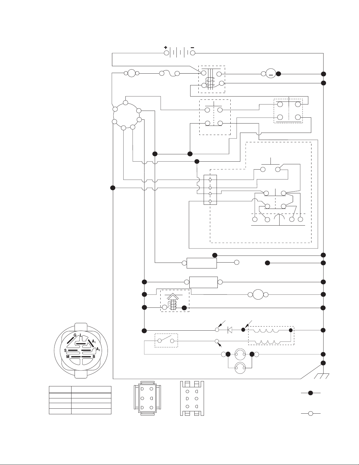
SCHEMATIC
SCH11
NOTE
YOUR TRACTOR IS
EQUIPPED WITH A SPECIAL
ALTERNATOR SYSTEM.
THE LIGHTS ARE NOT
CONNECTED TO THE
BATTERY, BUT HAVE THEIR
OWN ELECTRICAL SOURCE.
BECAUSE OF THIS, THE
BRIGHTNESS OF THE LIGHTS
WILL CHANGE WITH ENGINE
SPEED. AT IDLE THE LIGHTS
WILL DIM. AS THE ENGINE IS
SPEEDED UP, THE LIGHTS
WILL BECOME THEIR
BRIGHTEST.
RED
(OPTIONAL)
B
G
L
BLACK
A
AMMETER
S
M
A1
A2
WHITE
BATTERY
FUSE
BLACK
BLACK
BLACK /WHITE
BLUE
BLUE
FUEL SHUT-OFF
SOLENOID
(IF SO EQUIPPED)
RED
LIGHT SWITCH
DER
BLACK
IGNITION
(OPTIONAL)
FUEL
LINE
LIGHTING SYSTEM OUTPUT
5 AMP AC @ 3600 RPM
ORANGE
BROWN
SOLENOID
CLUTCH/BRAKE
(PEDAL UP)
2
3
1
6
JUNCTION
CONNECTOR
CHASSIS
HARNESS
UNIT
HOUR
METER
CHARGING SYSTEM OUTPUT
3 AMP DC @ 3600 RPM
DIODE
14 VOLTS AC MIN. @ 3600 RPM (LIGHTS OFF)
STARTER
BLACK
WHITE
REVERSE SWITCH
BLACK
BLACK
BLACK
BLACKBLACK
GRAY
PLUGS GAP
(2 PLUGS ON
TWIN CYL. ENGINES)
(NOT IN REVERSE)
SEAT SWITCH
(NOT OCCUPIED)
SPARK
BLACK
12V
POWER OUTLET
(OPTIONAL)
28 VOLTS AC MIN. @ 3600 RPM
(CHARGING SYSTEM DISCONNECTED)
ALTERNATOR
M
M
ATTACHMENT CLUTCH
(CLUTCH OFF)
BLACK
GRAY
SHORTING
CONNECTOR
BLACK
IGNITION SWITCH
POSITION
OFF
RUN/OVERRIDE
B+S+A1START
CIRCUIT
M+G+A1
B+A1
B+A1RUN
“MAKE”
L+A2
63
52
41
CHASSIS HARNESS
CONNECTOR
(MATING SIDE)
6
3
5
2
4
1
DASH HARNESS
CONNECTOR
(MATING SIDE)
3
HEADLIGHTS
WIRING INSULATED CLIPS
NOTE: IF WIRING INSULATED
CLIPS WERE REMOVED FOR
SERVICING OF UNIT, THEY
SHOULD BE RE-INSTALLED TO
PROPERLY SECURE YOUR
WIRING.
NON-REMOVABLE
CONNECTIONS
REMOVABLE
CONNECTIONS
TRACTOR - - MODEL NUMBER 96042010200, PRODUCT NO. 960 42 01-02
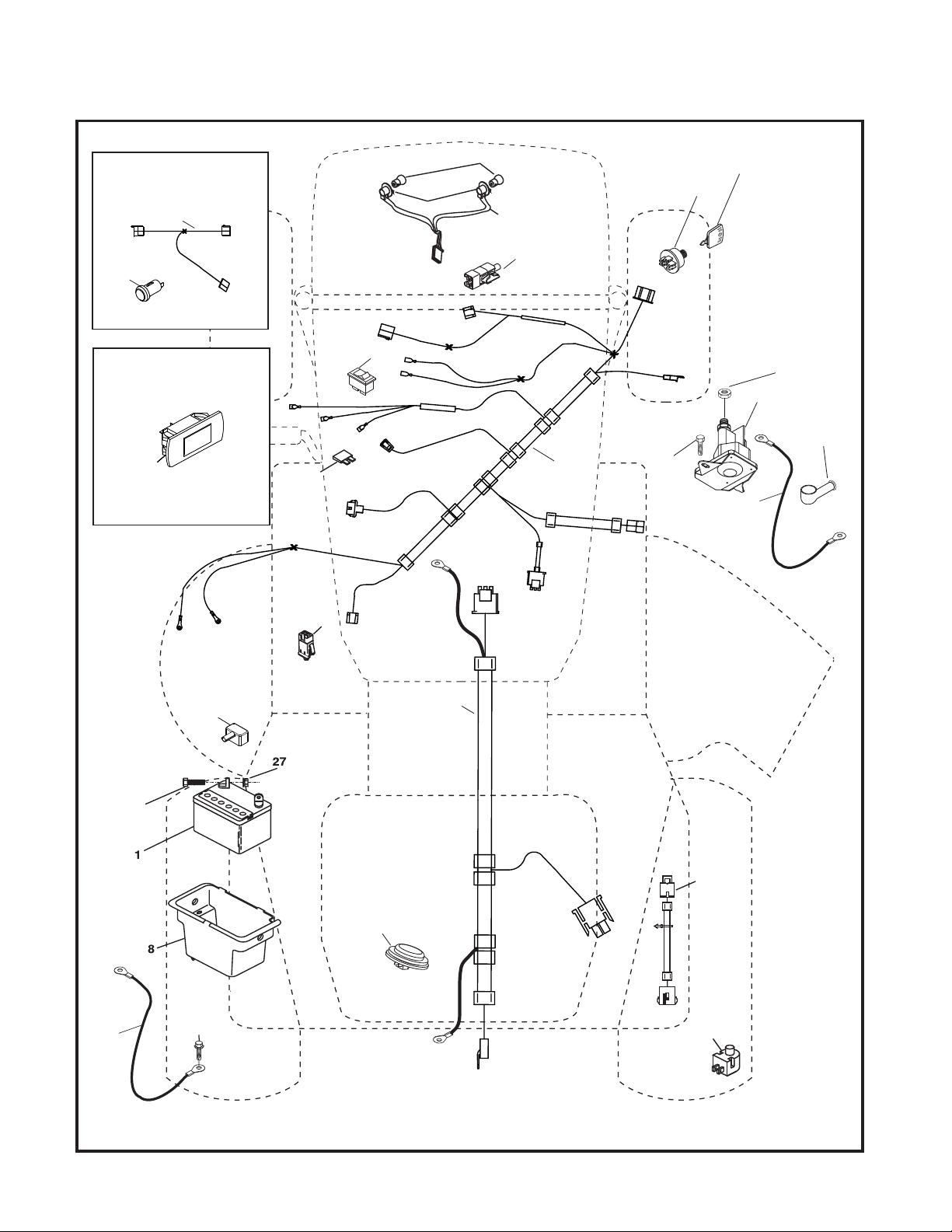
ELECTRICAL
T06S
With 12V Outlet Option
103
59
79
22
33
30
21
87
With Service Minder Option
4646
90
26
16
34
71
40
27
43
42
41
25
28
2
102
29
55
105
4

TRACTOR - - MODEL NUMBER 96042010200, PRODUCT NO. 960 42 01-02
ELECTRICAL
KEY PART
NO. NO. DESCRIPTION
1 163465 Battery
2 74760412 Bolt Hex Hd 1/4-20 unc x 3/4
8 193228 Box Battery
16 176138 Switch Interlock
21 400252 Harness Socket Light
22 4152J Bulb, Light #1156
24 400253 Cable Battery
25 412894 Cable Starter 6 Ga. BL/Red 14.5
26 175158 Fuse
27 73510400 Nut Keps Hex 1/4-20 unc
28 198885 Cable Ground
29 401545 Switch Seat
30 193350 Switch Ign
33 411933 Key/Chain
34 110712X Switch Light/Reset
40 401098 Harness Dash
41 17720408 Screw 1/4-20 unc x 1/2
42 131563 Cover Terminal Red
43 192507 Solenoid
55 17060512 Screw 5/16-18 x 3/4
71 400449 Harness Ign. Chass.
79 175242 Socket Asm. Bulb
87 197802 Switch Clutch Cable
90 435395 Cover Terminal
102 404454 Harness Pigtail
105 407568 Switch Reverse
NOTE: All component dimensions given in U.S. inches
1 inch = 25.4 mm
5
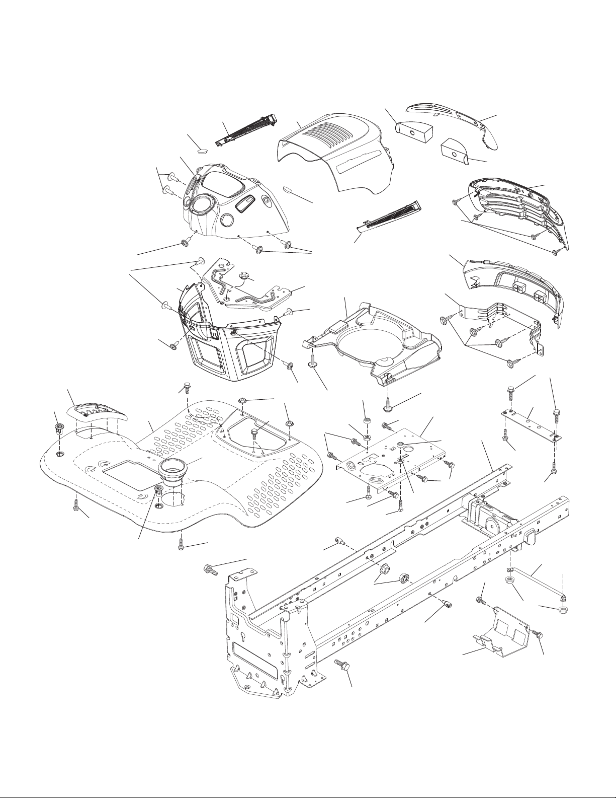
CHASSIS
TRACTOR - - MODEL NUMBER 96042010200, PRODUCT NO. 960 42 01-02
181
196
176
176
37
176
176
182
36
237
5
138
203
177
36
194
14
176
175
176
237
176
68
130
150
236
202
235
297
68
130
34
225
151
130
235
153
191
18
130
213
218
180
68
287
chassis-tex_TEX LT PRED_52
181
162
159
228
183
159
68
194
68
236
183
189
228
152
68
217
52
189
6

CHASSIS
TRACTOR - - MODEL NUMBER 96042010200, PRODUCT NO. 960 42 01-02
KEY PART
NO. NO. DESCRIPTION
5 400801X428 Dash
14 198416X615 Hood
15 183834X599 Lens Grille LH
18 400547X458 Grille Asm
34 196125 Plate Engine
36 17060512 Screw 5/16-18 x 3/4
37 414879X615 Fender
52 73680500 Nut Lock 5/16-18
68 17490508 Screw Thdrol 5/16-18 x 1/2
130 416358 Screw #10 x 0.750
138 193224X428 Cupholder
150 400267 Duct Heat Hood
151 187568 Bracket Pivot
152 199535 Shield Browning/Debris
153 400550X599 Lens
159 17000612 Screw 3/8-16 x 3/4
162 142432 Screw Hex Wsh Hi-Lo 1/4 x 1/2
175 199472 Crossmember
176 400776 Screw 10-24 x 5/8 Wshd Qdrx
177 195228 Bushing Steering
180 195457 Chassis
181 193102X428 Bushing Mtg. Fender Crgo.
182 407176 Dash Lower
183 74520520 Bolt 5/16-18 x 1-1/4
189 17000512 Screw 5/16-18 x 3/4
191 416502 Insert Reflective RH
194 73900500 Nut Lock Hex Flange 5/16-18
196 414579 Console Asm. Deck Lift
202 437912X428 Side Vent RH
203 437911X428 Side Vent LH
213 74760512 Bolt 5/16-18 unc x 3/4
217 409167 Rod Pivot Hood
218 196395 Hood Stop
225 400549X615 Bumper
228 195161 Stud Fastener
235 406129 Spacer Fender
236 73930500 Nut Center Lock 5/16-18
237 403704 Plug Mount Cargo
287 17600406 1/4-20 x 3/8
297 401827 Insert Reflective LH
NOTE: All component dimensions given in U.S. inches
1 inch = 25.4 mm
7

DRIVE
TRACTOR - - MODEL NUMBER 96042010200, PRODUCT NO. 960 42 01-02
56
51
221
42
49
52
64
190
184
186
187
185
189
50
51
167
35
15
188
159
159
29
160
17
143
216
161
153
163
211
171
52
51
125
153
170
215
227
226
125
211
214
166
80
125
125
210
222
33
230
205
drive-tex_K46_pedal_45_r2
183
116
2
225
116
183
2
205
73
99
1
73
230
33
8

DRIVE
TRACTOR - - MODEL NUMBER 96042010200, PRODUCT NO. 960 42 01-02
KEY PART
NO. NO. DESCRIPTION
1 - - - - - - Transaxle, TUFFTORQ K46 BT
2 123583X Key Square
15 19131316 Washer 13/32 x 13/16 x 16 Ga.
17 413678 Spring, Brake
29 403806 Rod, Brake
33 12000001 Ring E
35 401031 Rod, Brake, Park
42 8883R Cover, Foot Pedal
49 72110614 Bolt
50 194327 Pulley Idler Flat
51 73900600 Lock Nut 3/8-16
52 194326 Idler V-Groove 910" Offset
56 130969 V-Belt, Drive
64 197865 Shaft Asm. Pedal Brake Control
80 410024 Strap Torque
99 415742 Rod Bypass
116 73900500 Nut Lock Hex Flange 5/16-18
125 17000512 Screw 5/16-18 x 3/4
143 17490508 Screw
153 4497H Retainer Spring
159 76020412 Pin Cotter 1/8 x 3/4
160 169484 Retainer Clip
161 105709X Spring, Return, Clutch
163 401034 Rod Control Pedal K46
166 429164 Nut Push .625
167 405257 Latch Brake Parking
170 194322 Keeper Belt Centerspan
KEY PART
NO. NO. DESCRIPTION
171 72110616 Bolt RDHD 3/8-16 unc x 2
183 137057 Spacer Split
184 199996X505 Handle Parking Brake
185 72110622 Bolt Rdhd Sqnk 3/8-16 x 2-3/4 Gr. 5
186 194321 Spacer Retainer
187 19133210 Washer
188 194323 Link Clutch Ground Drive
189 194317 Bellcrank Ground Drive
190 194318 Keeper Bellcrank Ground Drive
205 121748X Washer
210 400980 Rocker Asm. Pedal Control
211 120183X Bearing Shaft Brake
214 421263 Pedal Forward Pad
215 197301X428 Pedal Reverse
216 196131 Bracket Pulley
221 403187 Retainer Spring Clip Handle
222 79212010 Washer 21/32 x 1-1/4 10 Ga. N/
PLTD
225 403319 Keeper Belt Trans.
226 401564 Bracket Mount Torque
227 17490512 Screw 5/16-18 x 3/4
230 188967 Washer Harden
NOTE: All component dimensions given in U.S. inches
1 inch = 25.4 mm
9

ENGINE
TRACTOR - - MODEL NUMBER 96042010200, PRODUCT NO. 960 42 01-02
18
15
21
20
37
97
28
96
37
84
42
12
82
81
1
45
87
69
79
94
2
29
OPTIONAL EQUIPMENT
SPARK ARRESTER
engine-tex_BS_2_r3
85
90
9
10

ENGINE
TRACTOR - - MODEL NUMBER 96042010200, PRODUCT NO. 960 42 01-02
KEY PART
NO. NO. DESCRIPTION
1 - - - - - - Engine Briggs Model No. 331877-1497-B1
2 188655 Muffler
9 194320 Keeper Belt Engine
11 400008 Clutch Electric
12 405472 Pulley Engine
15 407545 Tank Fuel
18 430220 Cap Asm
20 176636X428 Control Throttle
21 416358 Screw #10 x 0.750
28 401135 Fuel Line
29 137180 Spark Arrester Kit
37 123487X Clamp Hose
42 10040700 Washer Lock 7/16
45 73510400 Nut Keps Hex 1/4-20 unc
69 165291 Gasket
79 192334 Screw 5/16-18 x .75
81 148456 Tube Drain Oil Easy
82 428287 Valve Drain Oil
84 17060620 Screw 3/8-16 x 1-1/4
85 173937 Bolt Hex 7/16-20 x 4 5 Ga. 1.5
87 171877 Bolt 5/16-18 unc x 3/4 w/Sems
90 17000616 Screw 3/8-16 x 1
94 405450 Exhaust Tube
96 19091416 Washer 9/32 x 7/8 x 16 Ga.
97 17670412 Screw 1/4-20 x 3/4
NOTE: All component dimensions given in U.S. inches
1 inch = 25.4 mm
Engine Power Rating Information
The gross power rating for individual gas engine models is labeled in accordance with SAE (Society of Automotive Engineers) code J1940 (Small Engine Power & Torque Rating Procedure), and rating performance has been obtained and
corrected in accordance with SAE J1995 (Revision 2002-05). Torque values are derived at 3060 RPM; horsepower values
are derived at 3600 RPM. Actual gross engine power will be lower and is affected by, among other things, ambient operating conditions and engine-to-engine variability. Given both the wide array of products on which engines are placed and
the variety of environmental issues applicable to operating the equipment, the gas engine will not develop the rated gross
power when used in a given piece of power equipment (actual “on-site” or net power). This difference is due to a variety
of factors including, but not limited to, accessories (air cleaner, exhaust, charging, cooling, carburetor, fuel pump, etc.),
application limitations, ambient operating conditions (temperature, humidity, altitude), and engine-to-engine variability.
Due to manufacturing and capacity limitations, Briggs & Stratton may substitute an engine of higher rated power for this
Series engine.
11

STEERING
26
TRACTOR - - MODEL NUMBER 96042010200, PRODUCT NO. 960 42 01-02
72
33
45
1
63
57
64
20
16
35
28
21
59
58
13
71
28
22
60
57
19
9
66
9
7
8
63
8
7
67
2
6
4
67
6
61
steering-tex_STDHRS_12
68
69
14
15
70
12
62
14
15
5
13
8
13
53

STEERING
TRACTOR - - MODEL NUMBER 96042010200, PRODUCT NO. 960 42 01-02
KEY PART
NO. NO. DESCRIPTION
1 414803X428 Wheel, Steering
2 195968 Axle Asm., Front
4 403087 Spindle Asm., LH
5 403088 Spindle Asm., RH
6 6266H Washer, Thrust .75 x 1.230
7 121748X Washer 25/32 x 1-5/8 x 16 Ga.
8 12000029 Ring, Clip #T5304-75
9 121232X Cap, Spindle
13 121749X Washer 25/32 x 1-1/4 x 16 Ga.
14 10040600 Washer Lock 3/8
15 73540600 Nut, Crown Lock 3/8-24 unf
16 429374 Shaft Steering
19 194729 Plate Steering
20 400803X428 Boot, Steering
21 186737 Adapter, Wheel Steering
22 420537 Steering Support Lower
26 414854X428 Insert, Wheel Steering
28 17000612 Screw 3/8-16 x 3/4
33 10040500 Washer Lock 5/16
35 194732 Gear, Sector Plate
45 19113812 Washer 11/32 x 2-3/8 x 12 Ga.
53 188967 Washer Hardened .793 x 1.637 x .060
57 407465 Bracket Upstop
58 194747 Bolt Shoulder Sector Pivot CFM
59 194748 Washer Thrust Sector Steering
60 73971000 Nut Flange Lock 5/8-11
61 194740 Draglink, LH
62 194741 Draglink, RH
63 17000512 Screw 5/16-18 x 3/4
64 199849 Retainer Clip Spring Steering
66 71020748 Bolt Hex Fghd 7/16-14 x 3 Serr
67 194737 Bushing PM Front Axle
68 73900700 Nut Lock Flange 7/16-14 Gr. 5
69 199162 Washer 1.5 x .505 x .118
70 196197 Bracket Deck Susp. Front
71 190752 Shaft Extension Steering
72 428982 Bolt 5/16-18 x 4 W/Patch
NOTE: All component dimensions given in U.S. inches
1 inch = 25.4 mm
13

SEAT
TRACTOR - - MODEL NUMBER 96042010200, PRODUCT NO. 960 42 01-02
8
1
8
8
8
41
40
10
21
7
6
37
7
seat-tex_6.5SL_1_r1
KEY PART
NO. NO. DESCRIPTION
1 197511 Seat
2 180166 Bracket Pivot Fender
3 140675 Strap, Asm Fender
6 73800600 Nut, Lock w/Ins. 3/8-16 unc
7 124181X Spring, Seat Cprsn
8 171877 Bolt 5/16-18 unc x 3/4 w/Sems
10 196977 Pan, Seat
21 171852 Bolt, Shoulder 5/16-18
43
44
37
2
21
3
KEY PART
NO. NO. DESCRIPTION
37 73800500 Nut, Lock 5/16-18 unc
40 197661 Handle Slide
41 198200 Spring Latch
43 74760612 Bolt 3/8-16 unc x 3/4
44 19133812 Washer 13/32 x 2 3/8 x 12 Ga.
NOTE: All component dimensions given in U.S. inches
1 inch = 25.4 mm
14

DECALS
6
2
1
5,8
4,10
3,9
11
7
TRACTOR - - MODEL NUMBER 96042010200, PRODUCT NO. 960 42 01-02
11
9
4
2
5
14
KEY PART
NO. NO. DESCRIPTION
1 159737 Decal Brake/Clutch Symbol
2 429564 Decal Engine H.P.
3 400389 Decal Warning Symbols
4 140837 Decal Saddle Brake Parking
5 196841 Decal Warning Engine
6 196357 Decal Warning, Keep Hand Away
7 182166 Decal Deflect WRN. Cutfinger
9 429328 Decal Fender Logo
10 429334 Decal Sidepanel
10
7
12
6
1
3
KEY PART
NO. NO. DESCRIPTION
11 429326 Decal Ins Strg Whl
12 178302 Decal Operator Cruise
14 160369 Decal V-Belt Schematic
- - 193226X428 Pad Footrest LH
- - 400981X428 Pad Footrest RH
- - 166960 Decal Bypass
- - 162598 Decal Load Limit
- - 429122 Manual Operator's E&S
- - 429123 Manual Operator's Portuguese
- - 429125 Manual Parts
20
WHEELS AND TIRES
NO. NO. DESCRIPTION
1 59192 Cap Valve Tire
2 65139 Stem Valve
3 106222X Tire F T 15 x 6 0 - 6 Service
4 59904 Tube Front (Service Item Only)
5 106732X613 Rim Asm 6" Front Service
6 278H Fitting Grease (Front Wheel Only)
7 9040H Bearing Flange (Front Wheel Only)
8 106108X613 Rim Asm 8" Rear Service
KEY PART
9 138468 Tire R TS 20 x 8-C Service
10 7152J Tube Rear (Service Item Only)
11 104757X428 Cap Axle Blk 1 50 x 1 00
- - 144334 Sealant, Tire (10 oz. Tube)
NOTE: All component dimensions given in U.S. inches
1 inch = 25.4 mm
15

TRACTOR - - MODEL NUMBER 96042010200, PRODUCT NO. 960 42 01-02
MOWER DECK
117
70
67
7
152
240
197
64
57
43
7
46
42
56
2
57
242
38
144
241
55
36
40
145
59
46
63
147
34
30
30
33
68
32
31
21
195
118
122
119
117
46
116
21
123
195
198
3
21
37
116
119
118
30
38
1
56
60
113
47
19
46_tex_lt_pred_26
188
29
69
21
23
69
24
25
26
27
69
189
200
40
21
6
19
189
188
11
15
13
14
69
199
69
8
6
69
16

TRACTOR - - MODEL NUMBER 96042010200, PRODUCT NO. 960 42 01-02
MOWER DECK
KEY PART
NO. NO. DESCRIPTION
1 405049 Mower Housing
2 405507 Cover Mandrel LH
3 405506 Cover Mandrel RH
6 195186 Arm Suspension
7 416358 Screw #10 x 0.750 BOS Thread
8 193003 Bolt/Washer asm 7/16-20 unf
11 405380 Blade Mower
13 192872 Shaft Assembly, Mandrel
14 187281 Housing, Mandrel
15 110485X Bearing, Ball, Mandrel
19 196539 Bolt, Shoulder
21 73680500 Nut
23 192557 Bracket, Deflector
24 105304X Cap, Sleeve
25 197026 Spring, Torsion, Deflector
26 110452X Nut, Push
27 405357 Shield, Deflector
29 131491 Rod, Hinge
30 173984 Screw Thdrol Rolling Wsh Hd
31 187690 Washer, Spacer
32 197473 Pulley, Mandrel
33 400234 Nut, Toplock, Flanged
34 72110612 Bolt Carr Sh. 3/8-16 x 1-1/2 Gr. 5
36 197379 Pulley, Idler, 4.50 RAW
37 19131316 Washer 13/32 x 13/16 x 16 Ga.
38 432520 Keeper Belt Mandrel
40 73900600 Nut, Lock Flg. 3/8-16 unc
42 198410 Spring Trosion Brake
43 197256 Spring Torsion Retainer
46 137729 Screw
47 197250 Bracket Clutch Cable
55 197249 Arm, Idler
56 199092 Spacer, Retainer
57 17000616 Screw Hexwsh Thd 3/8-16 x 1
59 141043 Guard, Tuv Idler (94)
60 199471 Arm Brake Mower LH
KEY PART
NO. NO. DESCRIPTION
63 199477 Arm Brake Mower
64 405138 Linkage Brake
67 198398X428 Handle, Clutch Cable
68 405143 V-Belt
69 72140505 Bolt
70 401246 Clutch Asm.
113 17000510 Screw 5/16-18
116 4898H Bolt, Shoulder
117 188606 Wheel, Gauge
118 73930600 Nut Centerlock 3/8-16 unc
119 19121414 Washer 13/32 x 1-1/4 x 12 Ga.
122 197258 Keeper Belt Eng. LH
123 197259 Keeper Belt Eng. RH
144 199204 Keeper Belt
145 193197 Pulley Idler Primary
147 401872 Spring Return
152 435111 Cable Clutch Manual w/Spr.
188 195161 Stud Fastener
189 73900500 Nut Lock Hex Flange
195 17000612 Screw 3/8-16 x 3/4
197 19131312 Washer 13/32 x 13/16 x 12 Ga.
198 403149 Baffle Center Front
199 403150 Baffle Front RH
200 413524 Washer 13/32 x 1 x 1/2 11 Ga.
240 74520636 Bolt 3/8-16 unc x 2-1/4 Gr. 5
241 152927 Screw TT #10-32.5 3/8 Flange
242 415598 Port, Washout
- - 192870 Mandrel Assembly (Includes housing, shaft assembly, and bearing
only - pulley/nut/washer and blade
bolt/washers not included)
- - 418063 Replacement Mower, Complete
NOTE: All component dimensions given in U.S. inches
1 inch = 25.4 mm
17

TRACTOR - - MODEL NUMBER 96042010200, PRODUCT NO. 960 42 01-02
MOWER LIFT
91
7
87
10
90
89
98
3
97
100
2
88
88
97
87
89
lift-tex_14_r2
KEY PART
NO. NO. DESCRIPTION
2 422027 Shaft Asm., Lift
3 195231 Lever Asm., Lift RH
7 196492X428 Grip, Lever
10 196314 Spring Torsion
87 194209 Pin Cotter 7/16 Bow Tie Lock
88 410710 Spring Lift Assist
89 19191912 Washer Clear Zinc
90 194208 Pin Cotter 5/16 Bow Tie Lock
101
87
*Key 91 may be substituted for Key 101
KEY PART
NO. NO. DESCRIPTION
91 195181 Link Lift Susp Mower Rear
97 17000612 Screw 3/8-16 x 3/4
98 195270 Link Lift Susp. Front Mower
100 73930600 Nut Lock 3/8-16
101 407003 Link Asm. Lift Fixed
NOTE: All component dimensions given in U.S. inches
1 inch = 25.4 mm
18

SERVICE NOTES
19

08.23.10 AP Printed in the U.S.A.
 Loading...