


YADHAN
MODEL
F300A
F 30
2A
(ONE
(TWO
;:EAD)
~~READ)
PORTABLE
INSTRUCTION
BAG
CLOSER
tlfl=m!BJfS
I
' -
-
..,_
-
I..:.-
......
-.
2013.12

1 .
INTRODUCTION
1.1
PRODUCT
1.2
IDENTIFICATION
1.3
WARNINGS
1.4
ILLUSTRATIONS
2.
UNPACKING
3.
PREPARATION
3.1
ELECTRICAL
3.2
WORK
3.3
LUBRICATION
3.4
CONSUMABLES
3.5
THREADING
----· -· --· -· ----· -· · -· -· --· -· ----· -· ----· ----· -· ----· -· --· · 1
DESCRIPTION
····························································
AND
PROCEDURE
· · ·· · · · ·· · · · ·· ·· · · · ·· · · · ·· ·· · · · ·· · · · ·· · · · · · ·· · · · ·· ·· · · · ·· ·· · · 5
REQUIREMENTS
AREA
··················-·············-····························
· · · · · · · · · · · · · · · · · · · · · · · · · · · · · · · · · · · --· -· ----· -· --· ----· · · -· 5
· · · · · · · · · · · · · · · · · · · · · · · · · · · · · · · · · -· · · · · · · · · · · -· · · · · · · · · · · 5
THE
MODEL
TABLE
· · · · · · · · · · · · · · · · · · · · · · · · · · · · · · · · · · · · · · · · · · · · · · · · · · · · · · · · 1
COMPONENTS
OF
CONTENTS
-· · · · · · · · · · · -· · · · · · · · -· · · · · · · · · · · · · · -· · · · -· · · · · 1
2
· · · · · · · · · · · · · · · · · · · · · · · · · · · · · · · · · · 3
----·------·--·-·--·-·-··-·-·-··-·-·--·-·----· 5
· · · · · · · · · · · · · · · · · · · · · · · · · --· · · · -· · · · · · · · · · · 5
5
F3DDA
········································
6
THREAD
3.6
4.
OPERATING
5.
MAINTENANCE,
5.1
ROUTINE
5.2
LUBRICATION
5.3
DRIVE
5.4
FEED
5.5
KNIFE;
5.6LOOPER
5.7
MOTOR
5.8
NEEDLE
5.
9
PRESSER
5.10
6.
QUALITY
DOG · ·
THROAT
TENSION
THE
MAINTENANCE · · · · · · · · · · · · · · · · · · · · · · · · · · · · · · · · · · · · · · · · · · · · · · 9
BELT
THREAD
·································································
BRUSHES
· · · · · · · · ·
FOOT
PLATE · ·· · ·· ··
CONTROL
····················
MODEL
F300A
REPLACEMENT
· · · · · · · · · · · · · · · · · · · · · · · · · · · · · · · · · · · · · · · · · · · · · · · · · · · · · · · · · · · 9
······
···
··· ···
·· ··
···
·· ·· · ·· ··
· · · · ·
·· ·· ·· · ··
···················
·· ··
· · ·
·· ·· · ·· ··
PRESSURE
··············
···
··
· · ·
· · · · · · · · · · · · · · · · · · · · · · · · · -· · · · -· · · · · · · · · · · · · · · 18
· · ·
·· ·· · ·· ··
·
···········
PORTABLE
AND
ADJUSTMENTS
·········
·····
·· ·· · ··
·· ··
· · ·
··
· · ·
····
···
···
· · · · ·
·· · ·· ··
· · ·
··
···
··
···················
· · · · · · · · · · · · · · · · · · · · · · · · · · 7
· · ·· ·· · · · ·· ·· · · · 9
················
·····
··
···
·· ·· · ·· ·· ·· · ·· ··
··
· · · · · · ·
··········
· · · · · · · · · ·
·· ·· · ·· ·· ·· · ·· ··
··
· · · · · · · ·
···
··
· · ·
·· ··
····
···
··
·· ··
·········
· · ·
··
··
· · ·
· · · · · · · · · · · · · · · · · · · · · · · · · · · · · · · · · · · · · · · · · · · · · · · · · · · · · · 20
··
6
···
··
10
·
11
· · · · · 12
13
15
· · · · - 15
·· ··
19
7.
TROUBLESHOOTING
8.
SAFELY
DISPOSING
······················································
OF A MODEL
F300A
PORTABLE
·-·-·----···-··-
21
22

1. INTRODUCTION
1.1
PRODUCT DESCRIPTION
The
F300A series
machines.
They
sew bags
multi wall
For
proper operation.
made
paper
safety guidelines.
A variety
enhance
F300A
Standard
Can
1.2 IDENTIFICATION
There
attached
pr
otect
found on
It contains
of
special attachments
the
capab
hand-he
be
ordered for 110V/220V.
are two identificati
to
the
the
motor
the side
the
(l)
portab
bags,
le sewi
of
composite
become
ng
machines are
different materials, such
bags jute
familiar with the
(such as
iliti
es
and
support
ld, single-thread sewing.
on
electri
and
of
the
model
plates
cal
motor
make
housing.
identif
out
the
machine
ica
that
lines
(Fig.
tion,
the
the
operation
are
the
l )
(2)
weight
hand-he
bags
as
and
ld
plastic, woven polypropylene,
so
forth.
performance
suspension unit) are
of
the F300A portable.
attached
elec
run
effectively.
to the
trical requirements
The
and
(3)
serial number.
commercial
character
available
mach
ine.
needed
second
grade
istics
The
name
and
to
plate
to
plate
sewing
Is
The
information on the housing label provides
the card. In the
event
that
you
need
to
the
contact
necessary Information
your
parts or accessories, the information from this housing
to
quickly
and
accu
rately order the appropriate Items.
YAO
will
HAN
representative for
enable
the
@
to
comple
representative
te
Fig.
l
1.3
WARNINGS
•
•
The
model
contain moving parts
certain
are required
protection must
The
model
be
taken
from the drive components.
F300A
amount
F300A
to
series
of
to
operate and maintain the system. Proper eye, hand
be
sewing machines are hand held machines; therefore, care must
provide proper handling
portable sewing machines are driven by strong motors,
and
technical knowledge
worn while working with the
have pinch points
and
and
and
sharp edges. Therefore, a
familiarity with this type
F300A
operation
sewing machines.
of
the machines
of
equipment
and
foot
and
protection
• Read the manual carefully before making any changes to the model
• Always
Our parts are specifically designed for
performance
Use
•
Let
• Consult
•
The
materials are present (explosive gas, vapors, powders, dust or liquids).
• Frequently clean the
accumulation of material that
• Any sources of leaks of the machine's lubricating oil reservoir or
repaired Immediately
packed
use
genuine
and
of
non-YAO
the machine
YAO
HAN
model
F300A
and
safety hazards around the system.
YAO
HAN
spare parts (Including
YAO
HAN
equipment
safety.
HAN
parts
can
also void product warranty.
do
the
work.
concerning your specific application
machines are not suitable
machine
to
Do not pull the
to
prevent accumulation
may
cause a fire or malfunction.
prevent posslble contamination
bag
to
operate in area where explosive
YAO
HAN
lubricating oil).
to
provide optimum
or the materials through
and
sewing needs.
of
dust.
of
Do
pump
the product being
F300A.
this
to
must
It.
prevent
be
•
Do
not
use
aggressive cleaning products
• When in
F300A,
Other specific warnings
doubt
consult your local
about
operation, troubleshooting
YAO
HAN
representative.
appear
throughout
as
they may
this
manual.
and
2
damage
maintenance
the seals.
of
the
model

1.4
ILLUSTRATIONS
AND
COMPONENTS
71----------------1~
Left view
shown with thread knife
system
(Vista lzquierda con
de
corte
de
---10
sistema
hi/o,
1 , Needle bar guard
2.
Needle bar
clamp
3. Needle bar lever
4.
Wicking
5. Connecting rod
6.
Machine pulley
7,
OH
reservoir
8.
Belt
guard
9, Motor pulley
1
o.
Drive motor
11
, Looper
cam
and
and
handle
0
assembly
eccentric
12.
Cam
arm follower
1
3.
Presser
14. Needle bar
foot
3

1.4
ILLUSTRATIONS
AND
COMPONENTS
Bottom View
!,hown with thread
system.
(Vista
Inferior
cortador
con
de
knife
slstema
hJlo)
l.
Looper
rr::::::::::r-_,_
0
..
4---fil]
2.
Thread knife
3.
Throat plate
4,
Presser
5,
Presser
6.
Presser
7,
Presser
8.
Presser
9,
Needle
foot
bar
foot
lifter
foot llfter lever
foot spring
bar
clamp
l O. Thread eyelet
l l . Needle
l 2. Needle
13
. Needle
14. Feed
15.
Carrier block,
16. Looper assembly
bar
bar
dog
nut
feed
assembly
dog
4
2.
UNPACKING
Each
machine
designed
taped
incurred during shipping. After the unit
If
Report anything missing or
F300A serial number
reference
3.
PREPARATION
3.1
ELECTRICAL
The
are required
(3Gl
CAUTION:
Follow National Electrical
3.2
WORK
The
motion for the operator
quickly
sharp.
Other operators should keep out
works.
Operators should always wear proper
and
avoid getting
shut.
possible, record any suspected shipping
portable
.0mm,220-400V)
AREA
model
not wear loose clothing or jewelry. Long hair should
PROCEDURE
is
packed
to
protect
Before the unit
and
on your warranty card.
REQUIREMENTS
Is
wired
to
supply Incoming electrical connections.
Be
sure
F300A
and
the output
caught
in
a corrugated box with
the unit during normal shipping, storage and handing. It
Is
any
and
model
at
the factory for the voltage specified when ordered. Customers
is
recommended.
machine
machine
In
is
Code
should
and
the unit.
end
near the thread knife
the machine.
padding
unpacked, Inspect the box for any
is
unpacked, inspect the
damages
number
connected
(NEC)
of
and
be
The
arm"s
eye
operated in
damage
in
writing to the shipper
and
record these numbers for future
to building electrical ground.
any local electrical codes during use.
machine
reach from the area in which the
protection when operating this
with a digital or Polaroid
an
area
's Input
(or
thread
surrounding
SO
12/4
that
end
at
and
be
pulled
it.
which
signs
of
damage
machine
and
(12
allows freedom
the feed
tape
back
for
your
AWG/4
knife)
machine
and
damage.
camera.
model
wire)
dog
Is
very,
machine
tied
is
then
of
works
is
to
3.3
LUBRICATION
Note: Always
The
model
already
page
pump
through the clear
with the provided oil and
moving parts.
operation. Apply oil from the
3.4
CONSUMABLES
YAO
YAO
3).
must have a
HAN
HAN
• Cotton
use
genuine
F300A
In
the oil reseNolr
The
lubricant oil (#22
sewing thread:
(200-220
is
shipped with a small
machine
clean
end
This
will
YAO
HAN
#22
and
a separate container of oil. [see Machine Illustration,
Is
equipped
supply
of
the reseNoir.
press
dispense the correct
pump
TELLUS
grams)
with a manual oiling system.
of
oll
at
the button on the
every four
OIL)
TELLUS
amount
all times.
Prior
to
amount
OIL.
of
YAO
HAN
lubricating oil (#22)
The
The
oil level
operating the machine,
pump
[4)
of
oll for
hours
four
of
can
be
(4)
times
an
average four hours
operation.
reseNolr
viewed
fill
the reseNoir
to
lubricate the
and
of
5

4.
OPERATING:
MODEL
FJOOA
Before operating the
l.
Check for loose fasteners.
2.
make sure the all reservoir
3.
Push
the oil
4.
Make sure
5.
Make
6.
Make sure the thread
7.
Remove dirt
8.
Operator should not
away from the machine.
9.
Run
a couple
sure
pump
the
there
model
four times
machine
Is
an
and
debris from the machine.
of
test bags
F300A
Is
Is
connected
ample
is
properly threaded through the
be
wearing loose clothing
to
check
full.
to
lubricate the moving parts.
supply
check
through the followlng pre-start checklist:
to the appropriate electrical supply.
of
consumables near by. [Thread
If
the
machine
machine
and
long hair should
is
running properly.
and
and
is
chained off.
be
tied
Thread
(Ojete Pasador de
Pull
o ' · yclct
oll]
up
Hi
lo)
Needle
(Aguja)
I .~ __ '1
Flg.3
I .
. , I,
/ / ! ' ·
I I I ft
I I/ ~
I'
/ -
I I I -.
, ' / -/ -
t - i -
(
,: ~;-~}
l
[j
-~ (Ojete Pasador
1
...
~
-:-
i(
(-~---·/
Needle Bar Guide
(
Guia
/ :~: ·
:--
- ,-
fl
c;
I
·1_,..,.-1
-,._
'_
-
_ - 'Presser Foot
rr
· (Pie Prensador)
~\ I
._\
__
J
11
_.,·
/ . Thread PulloffEyelet
de
Hilo)
de Barra deAguJa)
7

3.5
THREADING
THE
MODEL
F300A
l . Disconnect the
2.
To
Install a new
the
top
The
cone
3.
Follow Fig.3
4,
Check that the thread passes around the tension disk properly,
Do
NOT
5.
Let
the thread stick out 2•
6.
In
order
between the presser foot
Turn
the pulley by
through
This
will start the chaining process.
material. before attempting
If this procedure
the needle.
3.6
THREAD
Tension
discs.
Too
the
Too
material
To
nut,
Test
Be
Is
loose a tension
bag
tight a tension will also cause the thread
alter the
about
the material until the desired stitch
sure
to
model
cone
of
the
cone
must not
and 4 to
wind the thread around the disk more than what
to
produce a thread chain, a
at least three
Is
TENSION
the degree
instead
to
re~lock
of
pucker.
amount
l /8 turn
upper tension nut.
nice firm stltches,
at
F300A from the electrical supply.
of
thread, push the thread
and
securely lock
be
able
to
rotate or wobble on the thread stand.
properly
hand
In
complete
not followed, the chain
of
resistance
wlll
cause
In
either case, the
of
tension, loosen upper tension nut. {Flg,4]
a ti
me
lead
(51
mm)
and
the throat plate before running the machine,
a c.lockwlse direction
cycles.
to
run a bag
the
the
thread
to
loosen the tension, or down
It
In
position with the wing nut. (Flg.2)
the
thread through the machine.
on the output side
piece
Run
the system
through the system.
wlll
thread meets
to
tear or
to
machine
appearance
clamping
of
bag
so
not start
in
will
tear or
may
Is
the
to
bolt through the hole
(Fig.4)
Is
shown.
of
the machine.
material should
sewn
bag
clear
out
and
the
passing between the tension
leave loose loops
will
cause polypropylene
not
chain off.
Turn
to
tighten the tension.
obtained.
be
placed
proceeds forward
the test
machine
bag
may
of
thread
the lower tension
at
break
on
bag
0· ,
11
f
_>--:-·--------
(
:-:
~-------------
---
I
k _____
: : -
/..;-·:
, ·---- I
I
----~--~--
--
:r
hread Clamping Bolt
\ (Perno
11,. (
Sujetado
6'1:.r~
r de Hilo)
d~~~)
\\~--~ Thread Stand
\ \ \ (Soporte de Hilo)
._
.,
I
\\
[f
ue
rca
pper Tension Nut
de
I : : : ___ ;>\ \ 'i
I
/>-~-
I .-- -
';=:::========-----· /
( / _j''-J
Flg.2
,...-'---'--
/ \_{ ·,
--
,...,
I )
___
_
(T
- uer
---
Wi
ng Nut
ca
.,
//
Mariposa)
6
Flg
,4
Tens
\
Tension Disks
(Disco de
;6n S~
pe
?
I ~,: .
\ . \\ \
:.;;;::·<
·
• •
...
,.·,~~\ ••••
.....
' · ·' •.
\1,Jfe'(
(Tu
~
lileas;On)
.}
.<1
\__
0
·.
;·i
!
. 1 I ;
..
, ' .
'"
'~
Lower Tcnstun Nut
erca
de Tensi
on Infe
c·-
.)
, -·
rior)

TURNING
THE
MACHINE
Hold the machine
found on the undersi
start machine.
ON
AND
OFF
In
your right hand with your forefinger on the switch button
de
of
handle. A slight finger pressure against switch button w
The
machine automatically stops when the pressure
is
released.
(Flg.6J
ill
SEWING
THE
Hold the
BAG
bag
TOP
(PLAIN SEWN)
top
in your left hand below where the stitch line
the starting side of the machine. Position the
presser foot
the
mach
After sewing a couple
starting button. Move your left
line
and
(
51
-7 6mm) off the tra
Remember not
The
model
plate.
With the
plate,
to
the thread chain
be
accomplished swiftl
Important! Always sew 4
Do
not
and
throat plate.
ine, when the start button
of
inches
The
machine
of
Is
the
hand
finish
sew
ing the
to
pull the
F300A
(Fig
.
7)
mach
by
slightly rotating the
is
ine running, pull the thread chain into the V-shaped slot
bag
II
Ing
edge
bag
equipped
machine
to
be
cut.
closed. Allow the
of
the bag.
through the machine.
with a thread knife
With
a little practice, the thread cutting operation
y.
to
6 Inches [l 02
sew
farther than four Inches down from the
bag
material between the machine's
will
automatically feed the
pressed.
bag
top, stop the
to
the leading
edge
model
at
the trailing
counter clockwise.
to
152mm]
top
machine
of
F300A
Let
the
This
above
of
the
Is
going
to
bag
be
and
through
by releasing the
the
bag
near the stitch
to
sew 2 to
machine
edge
3 Inches
do
the
work.
of the throat
at
rear
of
action brings the knife
the
bag.
product
(Fig.SJ
In
the
at
throat
can
bag.
Never Interfere
By
pulling the
back
the
bag
up
on
the machine, the quality of
the stitch
In
some cases
damage
0
0
~
. W TfH BIJTTON
(BOTON DE E1 C NOIOO)
wlll
to
H
AND
(
MANG
with
the feeding of the machine
bag
through, holding
or machine, or pulling
be
poor.
this
may
cause
the machine.
LE
O)
as
It
sews
THROAT
(PLACA GARGANTA)
@
THREAD KNIFE
Fig,
7 (LOCALIZACION E CORT
FREE TOP
(TO
PE
LIBRE)
across the
PLATE
LO
AO
bag.
ATI
Ot,;
R DE HILO)
©
4 10 6 in
(102 10 I 52mm
Flg.6 Fig.8
8
5.
MAINTENANCE,
5.1
ROUTINE
DAILY
l.
Keep the
2.
Fill
the oil reservoir with
3.
Check for loose fasteners
component
this
manual
MAINTENANCE
REPLACEMENT
machine
in
to
free
place
establish
AND
of
dust
YAO
HAN
and
that has a critical setting, refer to the appropriate section
the
correct setting.
MOTOR
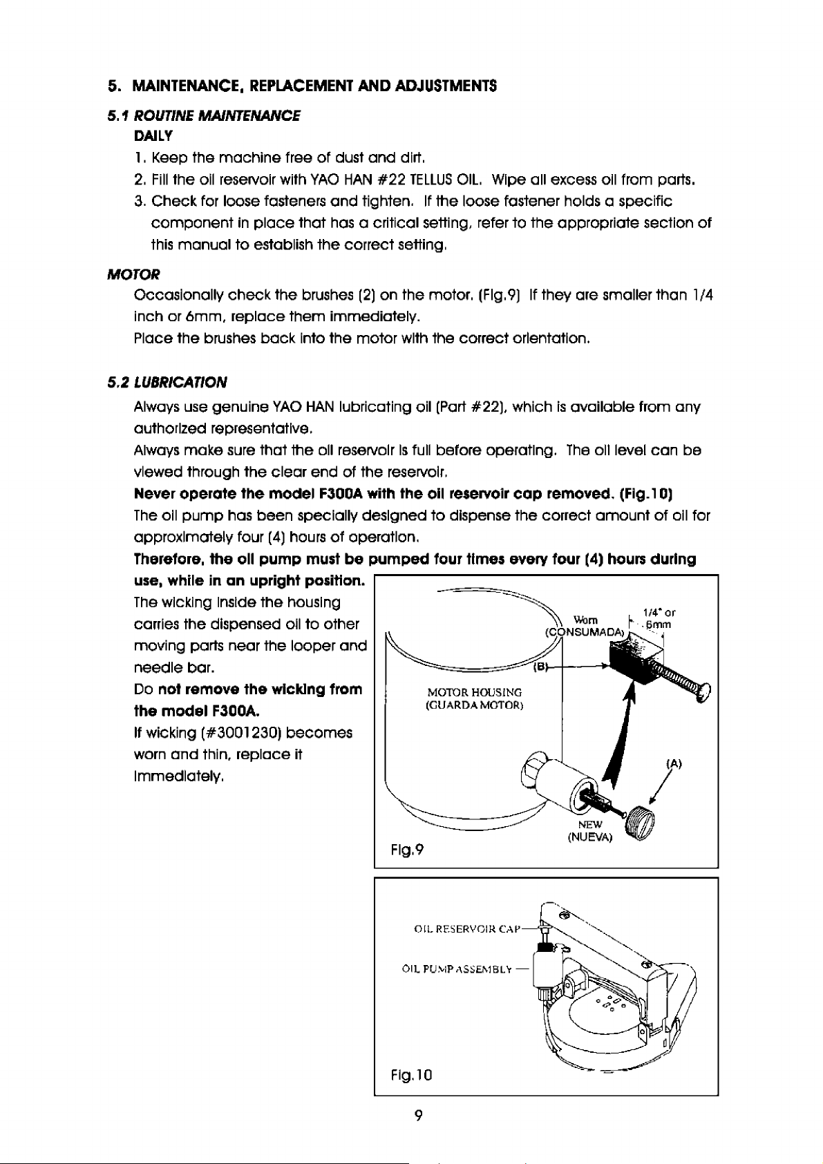
Occasionally
check
the
brushes
inch or 6mm, replace them immediately.
Place the brushes
5.2
LUBRICATION
back
Into the motor with the correct orientation.
ADJUSTMENTS
and
dirt.
#22
TELLUS
tighten.
(2)
on the motor. (Flg.9)
OIL.
If
the loose fastener holds a specific
Wipe all excess oil from parts.
If
they are smaller than 1/4
of
Always use genuine
YAO
HAN
lubricating oil
authorized representative.
Always
make
viewed through the
Never
The
operate
oil
pump
approximately four
Therefore, the oll
use, while
The
wicking Inside the housing
carries the dispensed oll
moving parts near the looper
sure that the oll reservoir
clear
end of the reservoir.
the
model F300A with the oil reservoir
has been specially designed
(4)
hours
of
operation.
pump
in
an
upright position.
must
to
other
be
and
needle bar.
Do not remove the wlcklng from
the
model
If
wicking (#3001230)
worn
F300A.
and
thin, replace it
becomes
Immediately,
Is
full before operating.
pumped
(Part
#22), which
is
available from any
The
cap
removed. (Fig.1
to
dispense the correct
four times every four (4)
MOTOR
(GU
ARDA
HOUSI
MOTOR)
NG
oil level
amount
hours
can
be
OJ
of
oil for
during
Flg.9
OIL
RESERVO
O
IL
PUMP ASSEMBL -
IR CAP-
Flg.10
9

5.3
DRIVE
BELT
l . Unplug
2.
Remove the thread
3.
Remove the
tube
4.
Loosen
5.
Press
belt.
6.
Install a new
both pulleys.
7. Apply tension
motor
two screws. (Flg.12)
The
belt
(Flg.13)
8.
Reattach
thread
cone
with
9.
Your
(section 3.5)
the
machine.
cone
from
handle
assembly
connected.
the
two screws (Fig.12) on
the
motor
mount
mount
belt
to
the
hinge
completely
(#3001619) around
belt
by
and
tightening
must remain slightly flexible.
the
cone
back
on
the
wing nut.
machine
handle
holder. Place the thread
the
is
assembly,
machine
now ready
the
by
unscrewi
the
opening
and
and
secure
to
be
thread.
thread stand.
ng
the two screws (Flg.11)
hinged
closed
motor
to
allow slack for removal
the
the
the
Flg.11
mount.
leave
of
the
the
used
Right View
oil
Top View: Drive
Flg.12
Flg.13
Vista Superior: Transmfs/on y Poleas
PR
OPER
(TENSION
BELT' TEVSION
APROPIADA
10
Hl
NGE MOTO
(91
SAG
DE
RA
OH MOTOR)
and
LA
CORREA)
R M
OU
ITT
motor Pulleys
de/
Motor

5.4
FEED
DOG
FEED
DOG
MAINTENANCE
The
feed
machine.
At
the factory the machine
Replace the feed
dog
determines the stitch length
If
the teeth of the feed
Is
set
dog
when it becomes dull
dog
at 3.75
and
pulls the
become
dull, the stitches will
stitches per Inch (6.
to
the touch.
bag material through the
8mm
(Fig.17
become
per
sti
)
shorter.
tch).
REPLACING
1.
2.
3.
4.
THE
FEED
Unplug the
Pl
ace
the
machine
Li
ft the pr
esse
Remove the thr
5. Remove the looper
6.
Unsc
rew the screw from the carrier block to remove the f
7. Place
do
8.
Screw the thr
9.
Follow the Instructions in the adjustment section to properly positi
a new feed
not tighten.
before tightening the socket
1
o.
Reassemble the looper cover
DOG
mach
ine.
r foot
oat
dog
oat
plate securely
in position
up
by
as
seen in the system
turning the lever lifter down. (Flg.1
plate. (Fig.15)
cove
r.
on the carrier block and
to
the
mach
cap
screw.
to
the machine.
ine.
Illustration
4)
eed
place
the socket
FEED
(ALIMENTAOOR DENTAOO)
dog
DOG
on
on
page
. (
Flg.16)
cap
back, but
the feed
3.
dog
Fig.14
Flg.
15
THROAT PLATE
(PLACA DE GARGAN TA)
Flg.
17
Flg. 16
11
OC
KET C.<\
(T
ORNILLO
'.:tBAElA
DEC'IC>LJE
(
POS
ALIMAENTADOR OE T
risc
R~W
)
rnGrrr-sr
OF FEED D
ICION M
CARRI
(BLOOUE
TRANSPORTADOR)
Posrrr
o.-
00
AS
ALTA DEL
AOO
ER BLOCK
J
)
ADJUSTING
l.
2.
THE
FEED
The
feed
dog
screws should
above
The
the throat plate, when
leading
edge
DOG
height
be
the leading edge.
3.
Once the orientation of the feed
Into position using the lower set screws
4.
Tighten the socket
5.
Assemble the looper cover to the machine.
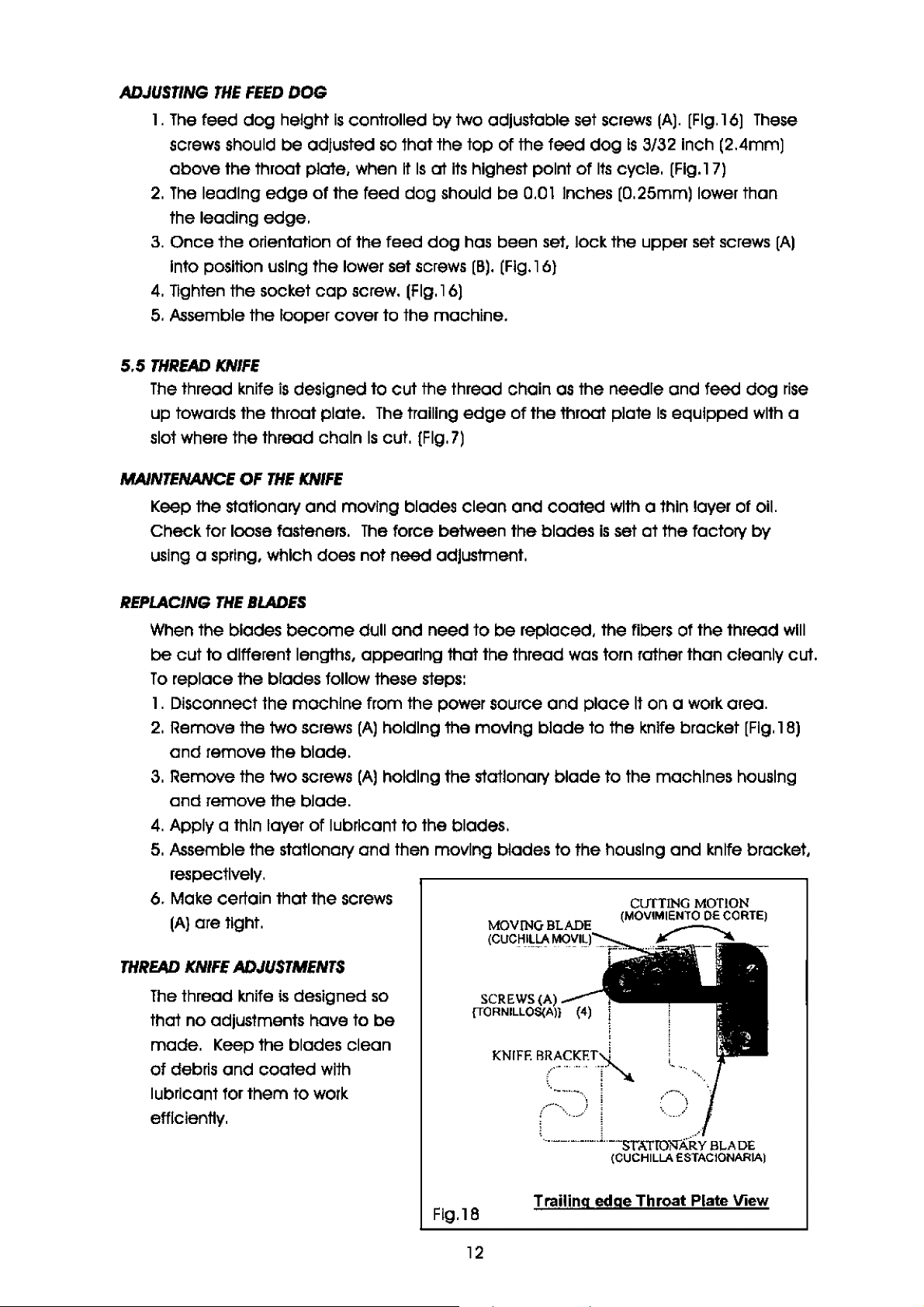
5.5
THREAD
The
KNIFE
thread
k.nife
is
designed to
up towards the throat plate.
slot where the thread chain
Is
controlled by two adjustable set
adjusted
of
cap
so
that the
It
the feed
dog
screw. (Flg.16)
cut
The
trailing
Is
cut. (Fig.
top
of
Is
at
Its
highest point
should
dog
be
has been
[B)
. (Flg.16)
the thread chain
edge
7)
screws
the feed
0.01
set,
of
the throat plate
dog
of
Its
Inches (0.25mm) lower than
lock the upper set screws
as
the needle
(A).
(Flg.16)
Is
3/32 Inch (2.4mm)
cycle. [Flg.17)
and
feed
Is
equipped with a
These
dog
[A)
rise
MAINTENANCE
Keep the stationary
Check for loose fasteners.
using a spring, which does not
REPLACING
When
be
cut to different lengths, appearing that the thread
To
replace the blades follow these steps:
l . Disconnect the machine from the power source
2.
Remove the two screws
and
3.
Remove the two screws
and
4.
Apply a thin layer
5.
Assemble the stationary
OF
THE
KNIFE
and
THE
BLADES
the blades
become
remove the blade.
remove the blade.
of
moving blades clean
The
force between the blades
need
dull
(A)
holding the moving
(Al
holding the stationary
and
need
adjustment.
lubricant to the blades.
and
then moving blades to the housing
respectively.
6. Make certain that the screws
(Al
are tight.
and
coated
to
be
replaced, the fibers of the thread
and
blade
blade
with a thin layer of oil.
Is
set
at
the factory
was
torn rather than cleanly cut.
place
to the
It
on a work area.
k.nlfe
to the machines housing
and
MOV
ING
HI
BLADE
LLA
MOV
IL)
(
CUC
bracket
[Fig.
knife bracket,
by
wlll
l
BJ
THREAD
KNIFE
The
thread knife
ADJUSTMENTS
is
designed
that no adjustments have to
made.
of
Keep the blades clean
debris
and
coated
with
so
be
SCREWS (A)
{TORNILLOS(A)}
KNI
FE Rc~~KET~
lubricant for them to work
,,~--
efficiently.
-, ....
l_·--·-------.L .
Flg.18
12
Trailing edge Throat Plate View
I
;
!
!
i
...
...
.....
..
...
-.
..
.
\ i
,.,.-'
! -
(CUCHILLA ESTACIONARIA)
..
ST
.1.
TfOli
'·-,,.)
f/4j
i·~
BLAD
E

5.6
LOOPER
MAINTENANCE
Periodlcally
involve critical settings. refer
adjustments.
check
the
REPLACING A LOOPER
l , Unplug
system Illustration,
2.
Raise
3. Rotate
You
4.
Remove
5.
Remove the
6. Remove
7,
Remove
8.
Remove
9. Install
loper
The
bottom
THIS
ADJUSTMENT
10. Tighten
11 , Replace
Section 5.8.
12.
Turn
check
and
Refer
the
machine
the
presser
the
machine
may
wish
to
the
needle
looper
the
throat
the
feed
the
looper
the
new
looper
faces. the
looper
of
IS
VERY
the
the
machine
the
needle.
to
Looper stroke adjustments
set screw.
Is
Inserted
the
looper holder.
IMPORTANT
OF
looper
the
needle
settings
looper clearance adjustment.
13.
Replace
14.
Replace
correctly
Replace
15.
the
throat plate.
the
feed
on
the
the
looper
fasteners for
to
and
place
page
foot
remove
dog
THE
height adjustment screws. (section 5.4)
3.
using
pulley
the
for safety. (Section 5.8)
cover. (Fig.15)
plate/
by
removing
from
the
into
the
completely
FOR
MACHINE.
set screw
as
described
pulley manually
between
dog
making sure
cover
the
looper
the section
It
on
a workbench
the
11ft
lever. (Flg.14)
manually
pulley cover, (Flg.11)
looper
looper
THE
(A)
the
and
until
the
holder
holder. Make sure
to
the
(Flg.19)
In
and
looper
and
that
check
In
this
the
socket
by
It
Is
to
see
assembly.
manual
In
the
feed
dog
cap
screw. (Flg.16)
loosening
LOOPER--+lf
(OJOGUIA)
Flg.19
set
that
all screws are tight.
To
tighten fasteners
that
describes
position shown
is
at
its
lowest position.
the
set screw
that
the
flat side
the
(A),
B
I I
that
by
the
(Flg.19)
of
the
I
I
'·
LOOPER
• Looper Stroke Adjustments
ADJUSTMENTS
1.
Put
the
machine
2.
Raise
the
presser
3.
Remove
4.
Remove
5.
Remove the
Turn
6.
left of the needle.
You
the
may
the
the
machine
want
on
a flat surface. with
foot
with
looper
throat plate.
feed
cover. (Flg.15)
dog
pulley until
to
remove
by
the
lifting lever. (Fig.14)
unscrewing
the
the
pulley
the
looper
cover
the
looper
socket
Is
at
for easier
cover
cap
maximum
13
facing
screw
back
access
you.
(page
(A),
(Flg.16)
stroke position
(Fig
., 11)
4)
to
the

7.
At
this
moment. the distance between the point
the needle must
A gage,
8.
If
that distance
9. Loosen screw
(#3001464)
Is
[A)
reaching the distance
be
of
0.03 inches (0.8mm).
Is
available through your
not correct. take off the housing cover.
of
the
cam
arm follower (Flg.20)
of
0.03
Inches (0.8mm). Tighten the screw
of
YAO
and
the looper
HAN
representative.
and
the left side
(Flg.1)
turn the looper shaft until
(A).
• Looper Clearance Ad}u,tmenf
This
setting
foot lifted
is
that the point of the looper passes behind the needle, as close to the "needle
scarf"
If
the clearance between the needle scarf
is
best seen from the left side
and
the throat plate
as
possible, without touching
and
feed
it,
(Fig.21)
of
the machine [Input side), with the presser
dog
removed,
and
looper needs to
The
goal
be
of
this
adjusted, follow
these steps:
1.
Rotate the machine pulley until the looper
Do
not forget to always rotate the pulley
is
directly behind the needle.
of
the machine clockwise, looking from
the top.
2.
Loosen the socket
3.
Move the looper holder on the looper shaft until the looper
as possible to the needle scarf without actually touching
pass
a sheet of
4.
When
this
step
5. Rotate the machine pulley through a couple
the looper clear the needle both on the
6.
When
throat plate
you have
and
cap
screw
paper
Is
between the
complete, tighten the socket
(D)
on the looper holder. (Flg.21)
back
up
made
and
verified all
of
the adjustments, replace the feed dog,
looper cover.
of
the needle
cap
of
complete
stroke
Is
positioned
It.
You
Should
and
the looper edge,
screw
and
(DJ
on the looper holder.
cycles to
be
the back. stroke of the cycle.
of
adjustment
as
closely
be
able to
sure
that
CAM
ARM
Flg.20
(A)
--t--i---+-
::-.
,
~~-__:::i(B
FOLLOWE
IELA
\ EL EXCENTRICO)
~~~PER
s11An
L_" E o,o GU
1
I
14
<A
R
)
Flg.21
NEEDLE
I PORTA GU
LOO
(EJE
DEL
(AGUJA
)
IA)
PER SHAFT
O.JO
GUIA
LOOPER
(OJOGU
IA)
)

5.7
MOTOR
MOTOR MAINTENANCE
The
schedule the brushes should
The
continuous periods without stops.
They
closing operations.
The
properly. (Fig.22
We
BRUSHES
motor should
motors used on the
are produced specifically for numerous
brushes should
recommend that the brushes
be
kept clean
be
and
9)
at
and
free
of
be
checked.
model
F300A
least l /4 Inch [6mm)
portables are not designed to
be
checked after every 100 hours
debris
starts
In
length
and
liquids. On a regular
and
stops
as
Is
In
order for the motor to
run
for long
the case for
of
use
.
bag
run
REPLACING
To
l.
2.
3.
4.
5.
5.8
NEEDLE
NEEDLE
The
adjusted with the 3/8 Inch wrench provided. Periodically
make certain that
strip the threads or the nut surface.
Do not use pilers.
THE
BRUSHES
check
Unplug the machine.
Unscrew the two brush holder caps
brushes
Check the length.
machine.
Be
If
Replace the brush holder caps
and
replace
(BJ.
(Flg.22)
sure
to
have new brushes
the brushes
MAINTENANCE
needle
Is
need
held
the
brushes follow this procedure.
If
they are
to
be
In
the needle bar by using the needle bar nut.
It
Is
tight
still
useable, replace them
on
hand.
replaced,
[A).
and
that the needle
[A)
from the motor
go
ahead
and
take out the used
and
and
Insert the new brushes.
check
Is
not loose or dull.
continue
The
the needle bar nut
to
nut should
Be
careful not
use
the
be
to
to
~
1OTOR
(GU ARDA MOTOR)
Fig.22
HOUSING
15
Wo
rn
(
CONSUMA0A
~- 1/4"
J ,
.§mm
Ji~
'
/'
e
or

REPLACING
THE
NEEDLE
l , Unplug the machine
system Illustration,
2.
Raise
the presser foot
manually until the needle bar
3.
Loosen
4.
Remove the needle.
5.
Fully
needles.
Looking from the bottom side of the machine, the needle's long groove should
face
6.
The
To
towards the celllng.
Place a coin or small flat object
The
7,
Tighten the nut
does not require excessive force to tighten.
8.
Lower
9, Check
the throat plate and presser foot.
l
0.
Thread the machine.
the needle bar nut
Insert
the new needle
you
and
the needle scarf should
groove edges should
check
this,
place
face
of
the coin should
the presser foot.
to
see
If
and
page
(A)
to
the needle
3.
with
the machine
[You
may
clamp
place
be
on a workbench
the lifting lever (Fig.14)
Is
at
Is
highest position.
(A)
with the 3/8 Inch wrench. (Flg.23)
in
the needle bar.
be
on the back.
parallel to the
so
that the bottom
wish
to remove the pulley cover
on
the groove.
be
parallel with the bottom
the needle
is
passing through the middle
In
place.
Always
face
In
the orientation shown
and
of
the machine bottom.
The
rotate the machine pulley
use genuine
of
the machine
face
nut
Is
designed
of
the needle guard on
YAO
HAN
Is
pointing
and
handle.
of
the machine. (Flg.24)
so
In
the
D5
(Flg.11
that It
up
),
Flg.24
NEEDLE
(MUESCA DE AGUJA)
}
Flg.23 Fig.25
SCARF
16
@

NEEDLE
Needle
ADJUSTMENTS
Height Versus Looper
l . Always adjust the needle height after the looper stroke adjustments has been
See the Looper Stroke Adjustment
2.
Remove the looper cover. (Flg.26)
3.
Turn
the
machine
forward, toward the needle (which
4.
As
the looper passes behind the needle, the point
right) must line up, flush with the right
the looper hook
If
an adjustment
l.
Slightly loosen the screw
2.
Move the needle bar
3.
Be
sure that you
are performing
4.
When the proper setting
pulley
Is
seen 0.15 Inches down from
is
necessary, perform the following steps:
DO
this
In
a clockwise direction until the looper begins
(D)
on
up
or down until you reach the adjustment shown
NOT
ROTATE
step.
Is
reached, tighten the screw
and
Looper
Is
beginning
edge
the needle bar
THE
of
NEEDLE
Clearance
to
move
of
the looper [moving
the needle, as the
the
top
clamp
BAR
OR
Adjustment.
upward).
of
the needle eye. [Fig.27)
assembly. (Flg.28)
THE
MACHINE
(DJ.
bottom
PULLEY
to
to
edge
In
made.
come
the
of
Flg.27.
as
you
MAXIMUM
(MAx.lMO)
LOOPER
(OJO-GUIA)
Fig.27
.015"
NEEDLE MOTION
(MOVIMIENTO DE
LA AGUJA)
LOOPER
M0.10N
..,
(MOVIMIENTO DE
LA OJO-GUIA)
NEEDLE EYE
(OJO
DE
LA
AGUJA)
Fig.26
Fig.28
-,
--------=
Q
I
I
;
·,
, __ ,1
()
r
-·
(
('
I
I
.
=[
i
_ ,f
2:NE
j(BARRA
==----
-
:
L.
_:
LIT'
7i
j'
00
WHILE ADJUSTING
I
!J
1t
l'
~=
l
( NO ROTAR
MIE
'--!V
EDL.EBAR
DE
LAAGUJA)
D)
OONOTMOVE
WHILE
ADJUSTING
(NO MOVER
M!E TRAS AJUSTEJ
NOT ROTAIB
TRASAJUSTE)
17

5.
9
PRESSER
The
FOOT
presser foot firmly holds the
needle passes through the
feed
dog
as
It
pulls the
MAJNTENANCE
Periodically
check
foot hinges.
off
Wipe
the excess lubricant.
bag
material against the throat plate while the
bag.
bag
It
Is
also responsible for holding the
through the machine.
the fasteners to make sure they are tight
bag
against the
and
lubricate the presser
PRESSER
1.
Disconnect the
2.
Raise
3.
Turn
4.
Loosen the two set screw
(Flg.29)
5.
Attach the new foot
The
facing
6.
Once
the set screws
7.
Near the hole where the
passes through the foot, you
find the
If the needle doesn't travel
through the
hole, loosen the two screws
and
8.
Tighten the screws
the presser foot using the lifter
lever.
9.
Turn
so
couple
make
adjustments.
FOOT
REPLACEMENT
machine
from the power source
the presser foot using the
the
machine
set screw
(E)
pulley
to
are
so
that the needle
(El
on
the presser foot bar. Note the flat area
to
tighten down on these flat areas,
the correct direction.
the presser foot
Is
pushed
(E).
needle
will
needle
guide. (Flg.30)
middle
of
the guide"s
(F)
move
the
the guide.
machine
(Fl
and
pulley
lower
by
hand
that the unit goes through a
of cycles
any
necessary
and
11ft
lever. (Flg.14)
the
back
up
completely
Flg.29
and
place
is
in
the highest position.
of
the presser foot
onto the bar
:-)
' ,
.Jt:' (BARRA DE PIE PR8'1SADOR)
~ AREAPlAN'I
J
on a workbench.
and
remove the foot.
on
If
the presser foot
and
./
PRJ:SSU
FLAT
AREA
(EJ
I
I
the bar.
Is
aligned, tighten
rooT
OAR
j ~-1
I ;
I '
: !
Flg.30
18
--
..
--·
----
·,,
\
.,
i
, ,
/
,'
//
I '

ADJUSTMENTS
The
presser foot
It
should not have to
If
the force on the presser foot needs to
steps:
l.
Disconnect the machine from the power supply
2.
Remove the looper cover. (Flg.15)
3.
The
spring around the presser foot bar provides the force exerted
foot.
The
presser foot lifter assembly
the
with
4.
At the factory the holder
5.
Loosen the screw
the force.
6.
Tighten the screw
7.
Attach the looper cover to the machine.
8.
Plug
In
the machine
Is
holder.
set
at
the factory to
be
adjusted for
is
[G)
and
and
check the force
and
set
move
test
accommodate
bag
types.
be
changed,
Is
used
to
set the spring
at
1/4 Inch (6.4mm) to the frame
the holder. Compressing the spring
of
the presser foot.
It
on a
bag
sample.
most typical
proceed
and
place
at
on a workbench.
a specified compression
bag
types.
through the f ollowlng
by
the presser
as
seen
In
Fig.31.
wlll
Increase
5.10
THROAT
PLATE
MAINTENANCE
Keep the throat plate clean for smooth
Routinely check the three fasteners to
Check the teeth on the
replaced if the teeth feel
top
worn
.y-"E
i.
\ ·
·- ,
-~
---
face
,
))
bag
flow through the machine.
be
sure
they are tight.
of
the plate. Generally, the throat plate should
to the touch.
Q
be
,~
--
- -
t ¼ INCH
1(6,4MM
Flg.31
)
19

THROAT
ADJUSTMENTS
PLATE
To
replace the throat plate. follow these steps:
l.
Unplug the
2.
Lift
3.
Turn
rising
the
4.
Remove the three screws
the plate
5.
Install the new throat plate with the
same three screws
6.
Move the
through a couple
Check
feed
without touching.
If there
The
throat plate
misaligned with the throat plate must
contained
REPLACEMENT
machine
the presser
the
machine
and
above
top
surface
to
the housing. (Flg.32)
machine
to
see if the needle
dog
easily pass through the plate
Is
contact, make the appropriate adjustments.
In
this manual.
from the power supply
foot
using the lifter lever. (Flg.14)
pulley manually
the throat plate
of
the throat plate.
[A).
pulley manually
of
cycles.
is
designed
(A)
that hold
and
so
that
to
the point
and
the
top
the
Fig.32
It
does not have
be
adjusted based on the Instructions
and
place
In
the cycle, where the needle
of
the feed
Plain sew throat plate shown.
on a workbench.
dog
9
-111-(A)
to
be
adjusted. Components
teeth are even with
is
e
6.
QUALITY
The
determining their own specifications for
STITCH
A.
As
pattern
machine
B.
This
the
The
have either worn down or they are not grabbing the
between them.
Check the teeth on the feed
they are worn.
This
points.
The
Check the pressure on the presser foot.
Make
validate the setting
CONTROL
purpose
PATTERN
seen
pattern (Flg.33) represents a sporadic stitch line.
bag
bag
pattern
tension
of
this section
TYPES
In
Flg.33, this pattern represents a proper
Is
both even
at a good
not going through the
is
occasionally slowing down, because the feed
may
also represent the thread cutting through the
disk
pressure should
sure
It
presses
Is
to
and
straight.
rate
and
firmly down on the throat plate. Refer to Section 5.9,
of
the presser foot holder.
provide
The
held the
machine
dog
and
be
reduced.
guidance
bag
operator
bag
at
the throat plate surface. Replace them if
for quality control departments
closures.
bag
closure.
fed
the
bag
straight horizontally.
This
pattern
an
even
pace.
dog
bag
with enough force
The
top
through the
Is
or throat plate teeth
bag
stitching
the result
at
various
to
of
In
20

c.
STITCH
This
stitch line (Fig.33) has
skipped stitches.
Skipped stitches are caused
and
by the looper
they are
together properly.
The
precisely set
maintain proper chaining.
Refer
looper
(Sections 5.6
CHAIN
not
functioning
needle
and
to
the adjustments for the
and
needle.
QUALITY
needle when
looper must
In
order
and
5.8)
to
be
A~TraJgE:.
(Borde Uder) (Borde Trasero)
L
.--
~
c~-
Fig.33
Plain Sewn Bags Shown
While the sewing
disks.
(Flg.4)
If
the tension
through the
If
the thread tension
using your fingernail.
THREAD
Bargain priced threads are not
and
shelf llfe necessary for Industrial
quality problems that
breaks, erratic sewing performance such
breaking
Blended polyester
strength, uniform diameter
A 1 00% synthetic thread out performs cotton
has no llmltlng shelf llfe,
resistance
open
to
machine
In
the thread
bag.
Is
along the stitch line.
Is
a 1 00% synthetic sewing thread that has maximum seam
sunlight and, most Important, offers minimal thread breaks.
Is
creating the stitch, it pulls
Is
too
too
loose, then the
To
make
occur
Is
adjustments to
when using these bargain threads
and
Impervious
tight, then the thread
made
a special lubricated high speed finish.
back
stitching
the
to
meet
the
bag
sewing equipment.
as
skipped stitches and, worst
and
to
most chemicals
the
thread through the tension
may
actually begin
can
be
easily pulled apart
thread tension see Section 3.6.
tensile strength, yield standards
The
most
Is
frequent thread
cotton blend threads,
and
has a
good
to
cut
common
of
all, bags
Is
stronger,
UV
BAGS
No matter what type
setting the
The
machine
than normal
Further questions
YAO
HAN
7.
TROUBLESHOOTING
1. Stitch
A.
B.
machine
Is
bag
or
your local
Is
too loose.
Check the thread tension. (Section 3.6)
Check the sharpness
(Sections 5.4
of
bag
is
being closed
for the
set
at
the factory
is
used, the pressure on the presser foot
may
and
bag
type
and
to
sew most
be
directed towards the Technical Service Department
YAO
HAN
Distributor.
of
the
teed
5.
1
OJ
by
the
thickness should not
bag
dog
and
throat plate teeth.
21
model
types.
F300A portable, properly
be
overlooked.
In
the event that a thicker
may
have
to
be
reduced.
at

2. Stitch
Check the sharpness
3.
The
A.
B.
C.
D.
4.
The
A
B.
C.
D.
5.
The
A
B. Check the thread tension. (Section 3.5)
C.
D.
E
F.
Is
too short.
of
the feed
bag
Is
tearing
Be
sure your not holding
machine
feeds the
If
the
the
Check the pressure on the presser foot. (Section 5.
Has
accommodate
machine
Is
the
Check the power cord
If
the switch on the handle does not click when pressed, replace the switch.
(#3001626-1)
Check the motor brushes
thread
Is
the thread unrolling easily from the cone?
Check the thread guides
The
..
Use
If unable
Service Department
must
bag
bag
is
bag
at
the
bag
machine
keeps breaklng.
needle
lubricated thread.
to
at
the sewing line.
back
be
moved
through the machine. (Section l
moving on a conveyor,
the same rate that the
quality
is
no longer running.
Is
getting
troubleshoot, call your
changed
the new bag?
securely
connected
to
too
(YAO
at
YAO
dog
and
the
machine
across the
and
seed if there are any breaks.
and
replace them
and
make
hot.
HAN
HAN.
bag
be
feed
has the
to
sure
synthetic lubricated thread)
YAO
(Section l )
throat plate teeth. (Sections
from travellng across
at
the same rate that the
.4J
sure
the
machine
moves the
machine
the power supply?
they are clean.
HAN
representative or the Technical
9)
If
they are
bag
ls
being
through the machine.
been adjusted
too
short. (Section
5.4
bag
top.
feed
moved
to
and
dog
across
5.
5.
10)
The
71
The
6.
machine
of the
bag.
A Check the thread tension.
B.
Make
them.
C.
Is
the thread unrolling from the
D.
Check the teeth on the
are dull. (Sections 5.4
E.
Check
F.
Check if the looper
G.
Make
7.
The
need/es keep breaking.
A.
Check the looper
B.
Check the needle alignment
(Sections
8.
SAFELY
If
to
after
the oil
has been drained
metal scrap facility.
DISPOSING
a model
a nonfunctional state after years of service.
It
Is
safe
according
Is
skipping stitches
sure
the thread guides are clean and that thread
feed
and
If
the needle
sure
the
5.1 0 and
F3DOA
to
dispose
sewing
to
and
Is
loose or misaligned. (Section 5.8)
is
loose, worn or needle
machine
and
OF
AN
your appropriate local environmental regulations. After the oil
disposed of, bring the sewing
ls
needle alignment. (Sections 5.6
5.9)
MODEL
machine
of
It.
First,
or
does
not
cone
easily?
dog
and the throat plate. Replace them
5.10)
to
properly threaded.
to
the throat plate
F300A
becomes
drain all the oil out
damaged
It
should
make a thread
can
be
reset.
and 5.8)
and
presser foot needle guide.
beyond repair or simply worn
be
put out of service only
of
the machine. Dispose
head
to
a recycling center or
chain
easily pass through
at
the
If
end
they
of
22
 Loading...