

Page 1

M9961-03E070
SERVICE MANUAL
FUEL INJECTION EQUIPMENT
MODEL YPD-MP2/YPD-MP4 SERIES
Page 2

Introduction
This document describes the features, disassembly, reassembly and adjustment procedure of the fuel injection unit
(Model YPD-MP2,MP4) for Yanmar Diesel Engine Model TNV.
Fuel injection unit is an essential mechanism of diesel engines, and thus, has to be designed to allow fine adjustment to
the engine load.
Therefore, the components of the fuel injection pumps are required to be given high-precision. To meet this requirement,
we process and assemble them very accurately.
Accordingly, when performing disassembly and adjustment works in the market, keep the workbenches and their
environment clean to surely prevent dirt and dust from attaching to the components of the unit, and take special care that
the components are not rusted.
Please note that the specifications of the components are revised to improve the quality of the product, and thus, the
details of the changed specifications will be notified through the correction table every time the change occurs.
i
Page 3

Contents
1. FOR SAFE SERVICING
1.1. Warning Symbols
1.2. Safety Precautions
2. GENERAL INFORMATION
2.1. Outline of MP pump
2.2. Specifications
2.3. Outline of fuel injection pump
2.4. Construction of MP-Pump
2.4.1. Fuel Injection Part
2.4.2. Governor Part
2.4.3. Delivery Part
・・・・・・・・・・・・・・・・・・・・・・・・・・・・・・・・・・・・・・・・・・・・・・・・・・・・・・・・・・・・・・・・・・・・・・・・
・・・・・・・・・・・・・・・・・・・・・・・・・・・・・・・・・・・・・・・・・・・・・・・・・・・・・・・・・・・・・・・・・・
・・・・・・・・・・・・・・・・・・・・・・・・・・・・・・・・・・・・・・・・・・・・・・・・・・・・・・・・・・・・・・・・・・・・・
・・・・・・・・・・・・・・・・・・・・・・・・・・・・・・・・・・・・・・・・・・・・・・・・・・・・・・・・・・・・・・・・・・・・
・・・・・・・・・・・・・・・・・・・・・・・・・・・・・・・・・・・・・・・・・・・・・・・・・・・・・・・・・・・・・・・
・・・・・・・・・・・・・・・・・・・・・・・・・・・・・・・・・・・・・・・・・・・・・・・・・・・・・・・・・・・・・・・・・・
・・・・・・・・・・・・・・・・・・・・・・・・・・・・・・・・・・・・・・・・・・・・・・・・・・・・・・・・・・・・・
・・・・・・・・・・・・・・・・・・・・・・・・・・・・・・・・・・・・・・・・・・・・・・・・・・・・・・・・・・・・・・・・
・・・・・・・・・・・・・・・・・・・・・・・・・・・・・・・・・・・・・・・・・・・・・・・・・・・・・・・・・・・・・・・・・・・・・
・・・・・・・・・・・・・・・・・・・・・・・・・・・・・・・・・・・・・・・・・・・・・・・・・・・・・・・・・・・・・・・・・・・・
・・・・・・・・・・・・・・・・・・・・・・・・・・・・・・・・・・・・・・・・・・・・・・・・・・・・・・・・・・
1
1
2
4
4
5
6
7
7
8
17
2.5. Function of Component
2.5.1. F.O. Feed Pump
2.6. Timer Mechanism
2.6.1. Structure and Functions
2.7. C.S.D.(Cold Start Device)
2.7.1. Cold Starting Advancer
3. DISASSEMBLY ,REASSEMBLY AND INSPECTION
3.1. Disassembly
3.1.1. Separating the pump body from the governor body
3.1.2. Separating the governor weight CMP
3.1.3. Disassembling the hydraulic head
3.1.4. Separating hydraulic head CMP
3.1.5. Separating the cam shaft
3.1.6. Disassembling the hydraulic head CMP
・・・・・・・・・・・・・・・・・・・・・・・・・・・・・・・・・・・・・・・・・・・・・・・・・・・・・・・・・・・・・・・・・・・・・・・・
・・・・・・・・・・・・・・・・・・・・・・・・・・・・・・・・・・・・・・・・・・・・・・・・・・・・・・・・・・・・・・・
・・・・・・・・・・・・・・・・・・・・・・・・・・・・・・・・・・・・・・・・・・・・・・・・・・・・・・・・・・・・・・・・・・
・・・・・・・・・・・・・・・・・・・・・・・・・・・・・・・・・・・・・・・・・・・・・・・・・・・・・・・・・・・・・・・・・・・
・・・・・・・・・・・・・・・・・・・・・・・・・・・・・・・・・・・・・・・・・・・・・・・・・・・・・・・・・・
・・・・・・・・・・・・・・・・・・・・・・・・・・・・・・・・・・・・・・・・・・・・・・・・・・・・・・・・・・・・・
・・・・・・・・・・・・・・・・・・・・・・・・・・・・・・・・・・・・・・・・・・・・・・・・・・・・・・・・・・・
・・・・・・・・・・・・・・・・・・・・・・・・・・・・・・・・・・・・・・・・・・・・・・・
・・・・・・・・・・・・・・・・・・・・・・・・・・・・・・・・・・・・・・・・・・・・・・・・・・
・・・・・・・・・・・・・・・・・・・・・・・・・・・・・・・・・・・・・・・・・・・・・・・・・・・
・・・・・・・・・・・・・・・・・・・・・・・・・・・・・・・・・・・・・・・・・・・・・・・・・・・・・・・・・・
・・・・・・・・・・・・・・・・・・・・・・・・・・・・・・・・・・・・・・・・・・・・
・・・・・・・・・・・・・・・・・・・・・・・・・・・・・・・・・・・・・・・・
・・・・・・・・・・・・・・・・・・・・・・・・・・・・・・・・・・・
18
18
20
20
21
21
22
22
22
23
23
25
25
27
3.2. Disassembling the Governor
3.3. Reassembly
3.3.1. Re-assembling the hydraulic head
・・・・・・・・・・・・・・・・・・・・・・・・・・・・・・・・・・・・・・・・・・・・・・・・・・・・・・・・・・・・・・・・・・・・・・・・・
・・・・・・・・・・・・・・・・・・・・・・・・・・・・・・・・・・・・・・・・・・・・・・・・・・・・・・・・・・・・・
・・・・・・・・・・・・・・・・・・・・・・・・・・・・・・・・・・・・・・・・・・・・・・・・・・
ii
28
29
29
Page 4

3.3.2. Re-assembling Cam Shaft
3.3.3. Install the hydraulic head CMP.
3.3.4. Assembling the Hydraulic Head
・・・・・・・・・・・・・・・・・・・・・・・・・・・・・・・・・・・・・・・・・・・・・・・・・・・・・・・・・
・・・・・・・・・・・・・・・・・・・・・・・・・・・・・・・・・・・・・・・・・・・・・・・・・・
・・・・・・・・・・・・・・・・・・・・・・・・・・・・・・・・・・・・・・・・・・・・・・・・・・・
30
34
35
3.4. Re-assembling the Governor
3.5. Combining Governor and Pump Bodies
4. ADJUSTMENT OF FUEL INJECTION PUMP AND GOVERNOR
4.1. Preparations
4.2. Bottom clearance adjustment(Fuel Injection Timing)
4.2.1. The bottom clearance adjusting value and the Cam classification
4.3. Adjustment of Governor
4.3.1. Adjustment of No Load Max. Engine Speed
4.3.2. Adjustment of Fuel Limit Bolt
4.3.3. Adjustment of Torque-Rise Point
4.3.4. Adjustment of Reverse Angleich
4.3.5. Adjustment of Staring Injection Amount
4.3.6. Checking the Injection Stop
・・・・・・・・・・・・・・・・・・・・・・・・・・・・・・・・・・・・・・・・・・・・・・・・・・・・・・・・・・・・・・・・・・・・・・・・
・・・・・・・・・・・・・・・・・・・・・・・・・・・・・・・・・・・・・・・・・・・・・・・・・・・・・・・・・・・・・
・・・・・・・・・・・・・・・・・・・・・・・・・・・・・・・・・・・・・・・・・・・・・・・・・・・・
・・・・・・・・・・・・・・・・・・・・・・・・・・・・・・
・・・・・・・・・・・・・・・・・・・・・・・・・・・・・・・・・・・・
・・・・・・・・・・・・・・・・・・・・・・・・・・・・・・・・・・・・・・・・・・・・・・・・・・・・・・・・・・・・・・
・・・・・・・・・・・・・・・・・・・・・・・・・・・・・・・・・・・・・・・・・
・・・・・・・・・・・・・・・・・・・・・・・・・・・・・・・・・・・・・・・・・・・・・・・・・・・・・
・・・・・・・・・・・・・・・・・・・・・・・・・・・・・・・・・・・・・・・・・・・・・・・・・・・
・・・・・・・・・・・・・・・・・・・・・・・・・・・・・・・・・・・・・・・・・・・・・・・・・・・・・
・・・・・・・・・・・・・・・・・・・・・・・・・・・・・・・・・・・・・・・・・・・・
・・・・・・・・・・・・・・・・・・・・・・・・・・・・・・・・・・・・・・・・・・・・・・・・・・・・・・・
・・・・・・・・・・・・・・・・・・・・・
39
40
42
42
44
45
46
46
46
46
47
48
48
5. FUEL INJECTION NOZZLE
5.1. Functioning of fuel injection nozzle
5.2. Type/construction of fuel injection nozzle
5.3. Fuel injection nozzle disassembly
5.4. Fuel injection nozzle inspection
5.4.1. Washing
5.4.2. Nozzle inspection
5.5. Fuel injection nozzle reassembly
5.6. Adjusting fuel injection nozzle
5.6.1. Adjusting opening pressure
5.6.2. Injection test
6. TROUBLESHOOTING
・・・・・・・・・・・・・・・・・・・・・・・・・・・・・・・・・・・・・・・・・・・・・・・・・・・・・・・・・・・・・・・・・・・・・・・・・
・・・・・・・・・・・・・・・・・・・・・・・・・・・・・・・・・・・・・・・・・・・・・・・・・・・・・・・・・・・・・・・・・・・・・
・・・・・・・・・・・・・・・・・・・・・・・・・・・・・・・・・・・・・・・・・・・・・・・・・・・・・・・・・・・・・
・・・・・・・・・・・・・・・・・・・・・・・・・・・・・・・・・・・・・・・・・・・・・・・・・・・・
・・・・・・・・・・・・・・・・・・・・・・・・・・・・・・・・・・・・・・・・・・・・・・・・・・・・・・
・・・・・・・・・・・・・・・・・・・・・・・・・・・・・・・・・・・・・・・・・・・・・・・・・・・・・・・
・・・・・・・・・・・・・・・・・・・・・・・・・・・・・・・・・・・・・・・・・・・・・・・・・・・・・・・・・・・・・・・・・
・・・・・・・・・・・・・・・・・・・・・・・・・・・・・・・・・・・・・・・・・・・・・・・・・・・・・・
・・・・・・・・・・・・・・・・・・・・・・・・・・・・・・・・・・・・・・・・・・・・・・・・・・・・・・・・
・・・・・・・・・・・・・・・・・・・・・・・・・・・・・・・・・・・・・・・・・・・・・・・・・・・・・・・・
・・・・・・・・・・・・・・・・・・・・・・・・・・・・・・・・・・・・・・・・・・・・・・・・・・・・・・・・・・・・・・・・・・
・・・・・・・・・・・・・・・・・・・・・・・・・・・・・・・・・・・・・・・・・・・・・・・
49
49
49
50
51
51
52
53
53
53
54
55
6.1. Troubleshooting of fuel injection pump
・・・・・・・・・・・・・・・・・・・・・・・・・・・・・・・・・・・・・・・・・・・・・・・・・
iii
55
Page 5

6.2. Major faults and troubleshooting
・・・・・・・・・・・・・・・・・・・・・・・・・・・・・・・・・・・・・・・・・・・・・・・・・・・・・・
55
7. TIGHTENING TORQUES FOR MAIN BOLTS AND NUTS
7.1. Pump part
7.2. Mechanical governor part
8. TOOLS
・・・・・・・・・・・・・・・・・・・・・・・・・・・・・・・・・・・・・・・・・・・・・・・・・・・・・・・・・・・・・・・・・・・・・・・・・・
・・・・・・・・・・・・・・・・・・・・・・・・・・・・・・・・・・・・・・・・・・・・・・・・・・・・・・・・・・・・・
・・・・・・・・・・・・・・・・・・・・・・・・・・・・・・・・・・・・・・・・・・・・・・・・・・・・・・・・・・・・・・・・・・・・・・・・・・・・・・・
・・・・・・・・・・・・・・・・・・・・・・・・・・・・・・・・・・・・
58
58
59
60
iv
Page 6
1. For Safe Servicing
! Most accidents are caused by negligence of basic safety rules and precautions. For accident prevention,
it is important to avoid such causes before development to accidents.
Please read this manual carefully before starting repair or maintenance to fully understand safety
precautions and appropriate inspection and maintenance procedures.
Attempting at a repair or maintenance job without sufficient knowledge may cause an unexpected
accident.
! It is impossible to cover every possible danger in repair or maintenance in the manual. Sufficient
consideration for safety is required in addition to the matters marked CAUTION. Especially for safety
precautions in a repair or maintenance job not described in this manual, receive instructions from a
knowledgeable leader.
1.1. Warning Symbols
! Safety marks used in this manual and their meanings are as follows:
DANGER indicates an imminently hazardous situation,
which if not avoided, WILL result in death or serious injury.
WARNING indicates a potentially hazardous situation,
which if not avoided, COULD result in death or serious
injury.
CAUTION indicates a potentially hazardous situation,
which if not avoided, may result in minor or moderate
injury.
! Any matter marked [NOTICE] in this manual is especially important in servicing.
If not observed, the product performance and quality may not be guaranteed.
1
Page 7
1.2. Safety Precautions
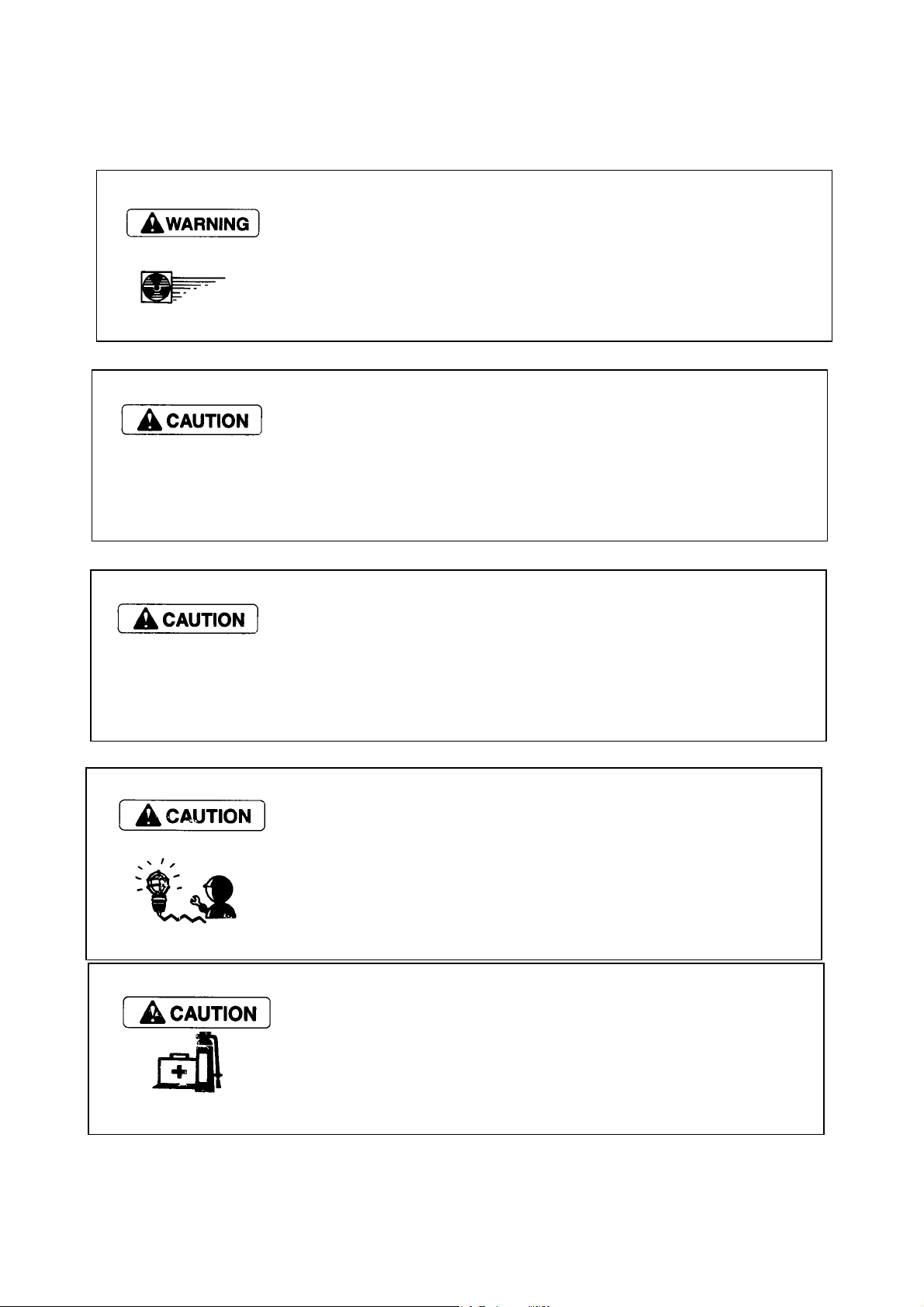
! Place allowing sufficient ventilation
Jobs such as engine running part welding and polishing the paint with
sandpaper should be done in a well-ventilated place.
Failure to Observe
Very dangerous for human body due to the possibility of inhaling poisonous
gas or dust.
! Sufficient wide and flat place
The floor space of the service shop for inspection and maintenance should
be sufficiently wide and flat without any holes.
Failure to observe
An accident such as a violent fall may be caused.
! Clean,orderly arranged place
No dust,mud,0il or parts should be left on the floor surface.
Failure to Observe
An unexpected accident may be caused.
! Bright,safety illuminated place
The working place should be illuminated sufficiently and safety.For a job in
a dark place where it is difficult to see,use a portable safety lamp. The
bulb should be covered with a wire cage for protection.
Failure to observe
The bulb may be broken accidentally causing ignition of leaking oil.
! Place equipped with a fire extinguisher
Keep a first aid kit and fire extinguisher c1ose at hand in preparation for fire
emergencies
2
Page 8
r
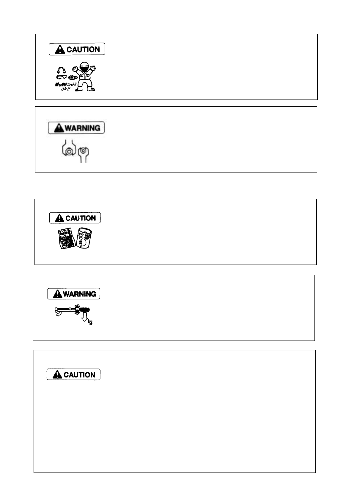
! Wears for safe operation
Wear a helmet,working clothes ,safety shoes and other safety protectors
suited to the job. It is especially important to wear well-fiting work clothes.
Failure to observe
A serious accident such as trapping by a machine may occur.
! Use of appropriate tools
Use tools appropriate for the jobs to be done. Use a correctly sized tool for
loosening or tightening a machine part.
Failure to observe
A serious injury or engine damage may occur.
! Always use genuine parts
Jobs such as engine running part welding and polishing the paint with
sandpaper should be done in a well-ventilated place.
Failure to Observe
Shortening of MP pump unit life or an unexpected accident may arise.
! Always tighten to the specified torque if designated in the manual.
Failure to Observe
Loosening or falling may cause parts damage or injury.
Observe the following instructions with regard to waste disposal.
Negligence of each instruction will cause environmental pollution.
! Waste fluids such as engine oil and cooling water shall be
discharged into a container without spillage onto the ground
! Do not let waste fluids be discharged into the sewerage,a rive
or the sea.
! Harmful wastes such as oil, fuel, solvents, filter elements and
battery shall be treated according to the respective laws and
regulations. Ask a qualified collecting company for example.
3
Page 9
2. General information
2.1. Outline of MP pump
MP pump is a fuel injection pump that has been newly developed to be installed on Yanmar direct injection system diesel
engines for the purpose of complying with the regulation for the exhaust gas emission that are becoming tighter in the
future.
The fuel injection pump is a fuel distribution type pump that supplies fuel to each cylinder of the engine through a
distribution shaft by using a single plunger unlike conventional rail system or distribution system pumps.
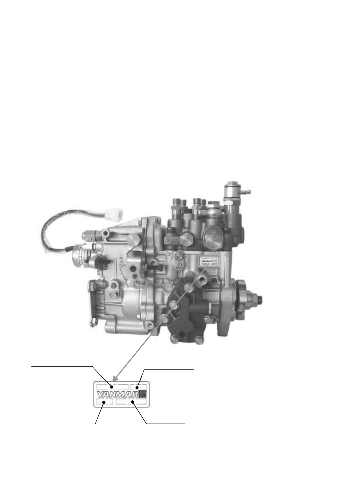
! Pump name plate
Fuel Injection Pump Asy. code
ID code for production Serial numbers
ID code for Exh.gas regulationFIE ASY code
Injection Pump No.
4
Page 10

2.2. Specifications
Model
Applicable Engine 3TNV82A /84(T)/88 4TNV84(T) /88
Plunger Diameter (mm) 9mm 10mm
Max. Cam Lift (mm) 8.1mm 10mm
Governor-System Mechanical All Speed Governor
Fuel Injection Timing Control
System
Fuel feed pump Forced Lubrication System With Trochoid Pump
Lubrication system Engine System Oil
Dry Weight (kg) 8.4 8.6 11.5
YPD-3MP2 YPD-4MP2 YPD-4MP4
Built-in Hydraulic Control Timer
4TNV94
/98(T)/106(T)
5
Page 11

2.3. Outline of fuel injection pump
Yanmar distribution type fuel injection pump YPD-MP consists of a hydraulic head that is equipped with a single plunger, a
single distribution shaft, and delivery valves for each individual cylinders, a pump housing that includes camshafts, and a
governor, all of which are integrated into the main unit of the pump.
For the feed of the fuel, the plunger moves up / down and the distribution shaft rotates with the revolution of the camshaft
to distribute the fuel among the cylinders individually.
Specifically, one revolution of camshaft completes three cycles (for three cylinder engine) of a process, including switching
over to the high pressure flow path to each cylinder with the distribution shaft, opening delivery valve, high pressure pipe,
fuel injection valve, and engine cylinders in this order. This process is repeated by the revolution of the camshaft.
< The Flow of the Fuel >
12/48
Fuel tank
orifice
Fuel filter
Electric fuel
feed pump
Water separator
Fuel injection pipe
Nozzle
joint
Injection pump
Plunger
Distributor
shaft
Fuel return
Timer piston
Thermo-element
Engine coolant
Accumulator
tappet
High pressure gallery
Overflow
orifice
Oil seal
Engine
Cam
oil
Engine crankcase
Torochoid pump
Low pressure gallery
Pressure control valve
6
Page 12
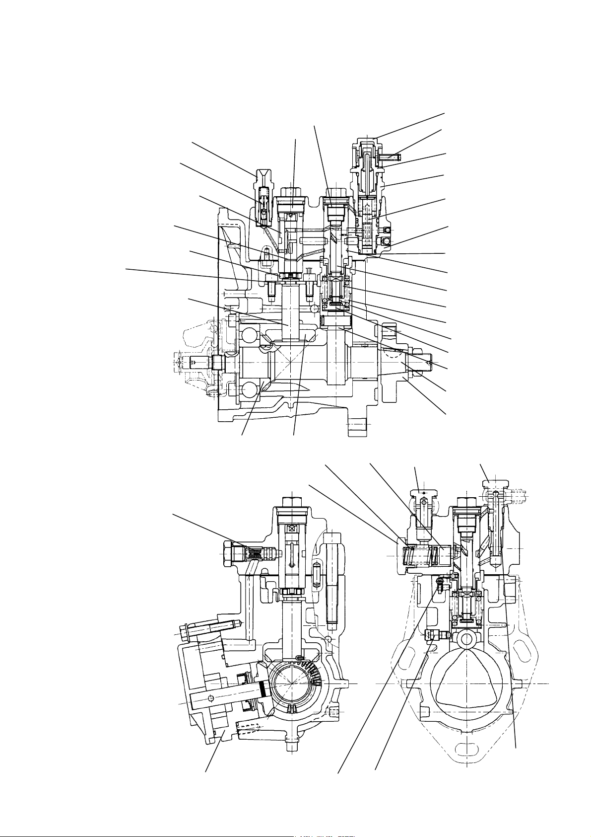
2.4. Construction of MP-Pump
2.4.1. Fuel Injection Part
Holder (delivery)
Delive ry valve CMP.
Sleeve (distribution shaft)
Distribution shaft
Joint (distribution shaft)
Removal stop
(Transmission shaft)
Transmission shaft
Plug (distribution shaft)
Plug (C.W.)
Plug (barrel)
Joint (C.W.)
Thermo element.
Holder (timer)
Piston (timer)
Hydrauric head
Packing (timer)
Barrel (plunger)
Plunger
Sleeve (control)
Spring (plunger)
Tappet (roller)
Retainer (spring)
Roller
Camshaft
Flange
Drive gear A
Strainer (A)
Spring (accumulator)
Plug(accumurator)
Drive gear B
Accumulator
Joint (FO inlet) Joint (overflow)
Strainer (B)
F. O. feed pump CMP Control rack
7
Whirl-stop (tappet)
Page 13

2.4.2. Governor Part
2.4.2.1. Construction of Governor
Usage condition of diesel engines are extremely varied,with a wide range of loads and speeds.The governor plays an
important role in the operation of the engine by quickly adjusting the position of the control rack to control the amount of
fuel injected, according to changes of engine speed.
It also automatically controls the engine to prevent engine speed from exceeding the maximum ,and keeps the engine
from stopping.
! Mechanical governor
Shaft (Control lever)
Fuel limiter CMP.
Torque spring
Control lever
Spring (governor)
Regulator lever
Stop solenoid
Link
Shaft (Governor lever)
Governor case cover
Angleich spring assembly
Camshaft
Governor weight
Sleeve (governor)
Governor lever CMP
The governor weight mounted on the end of the fuel injection pump cam shaft rotates around the governor support pin,
driven by the cam shaft, and is forced outwards by the centrifugal force acting on the weight.
The thrust force acting on the cam shaft due to this centrifugal force acts on the lower part of the tension lever through the
sleeve A starting excess fuel spring is mounted on the bottom of the tension lever.
0ne end of the governor spring is hooked to the right upper end of the tension lever, and the other end to the spring lever
of the control lever shaft.
8
Page 14
As the spring lever and control lever are mounted on the same shaft, when the control lever is turned towards full, the
governor spring is pulled and the load gradually increases.
Since the tension lever can move freely around the governor shaft on the player bearing, as speed increases and the
shifter is pushed to the left,the tension lever rotates clockwise, and when speed decreases,the tension lever rotates
counterclockwise.
The governor lever rotates smoothly on the second shaft installed on the tension leveb. The bottom part of this lever is in
contact with the sleeve through the shifter, which is in contact with the bottom of the tension lever through the excess fuel
spring. It therefore moves with the tension lever according to increases/decreases in engine speed.
The top of the governor lever is connected to the fuel pump control rack through the governor link. The movement of the
lever controls the volume of fuel injected by the pump. When speed increases the lever rotates clockwise to cause the
control rack to reduce fuel and when speed decreases the lever rotates counterclockwise to cause the control rack to
increase fuel, thus engine speed is controlled.
The top of the tension lever comes in contact with the stopper built into the top of the governor case to limit the maximum
fuel injection volume.
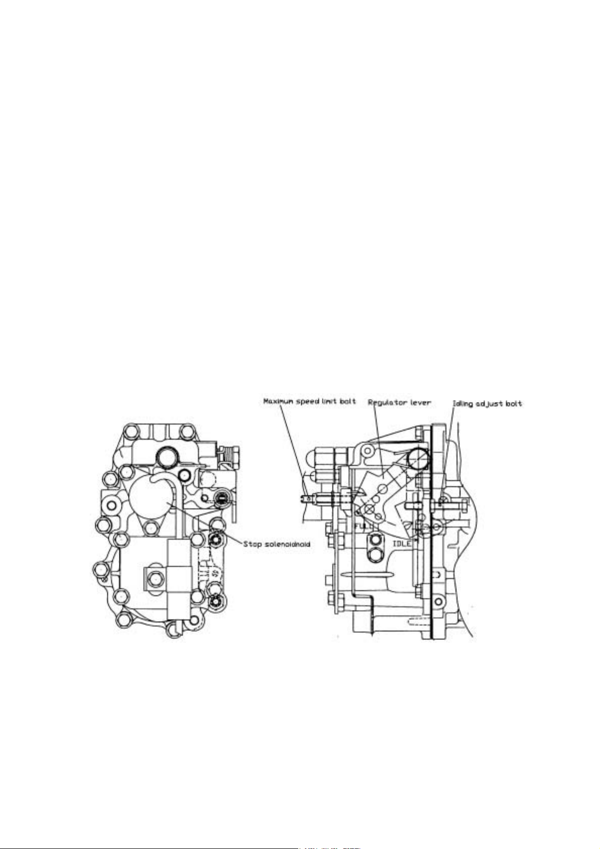
(1) Shape of control and stop levers
The control and stop levers that operate the governor have different shapes depending on engine design and
method of attachment, as seen in the pictures below.
The motion of the control lever is regulated by the maximum speed adjustment bolt and the idling adjustment bolt. This
maintains the necessary engine speed.
9
Page 15
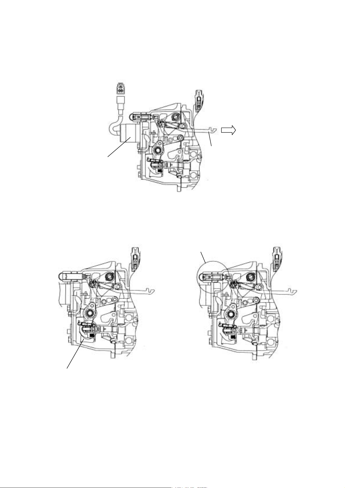
(2) Engine stop device
The magnetic solenoid is equipped to stop the engine.
Injection volume
Decrease
Stop solenoid
Link
(3)Torque rise equipment
As mentioned before,this governor has a structure that allows you to equip it with an anglich and/or torque spring as
torque rise equipment. In this way the requirements for different engines can full filled.
Torque spring CMP
Angleich spring CMP
10
Page 16
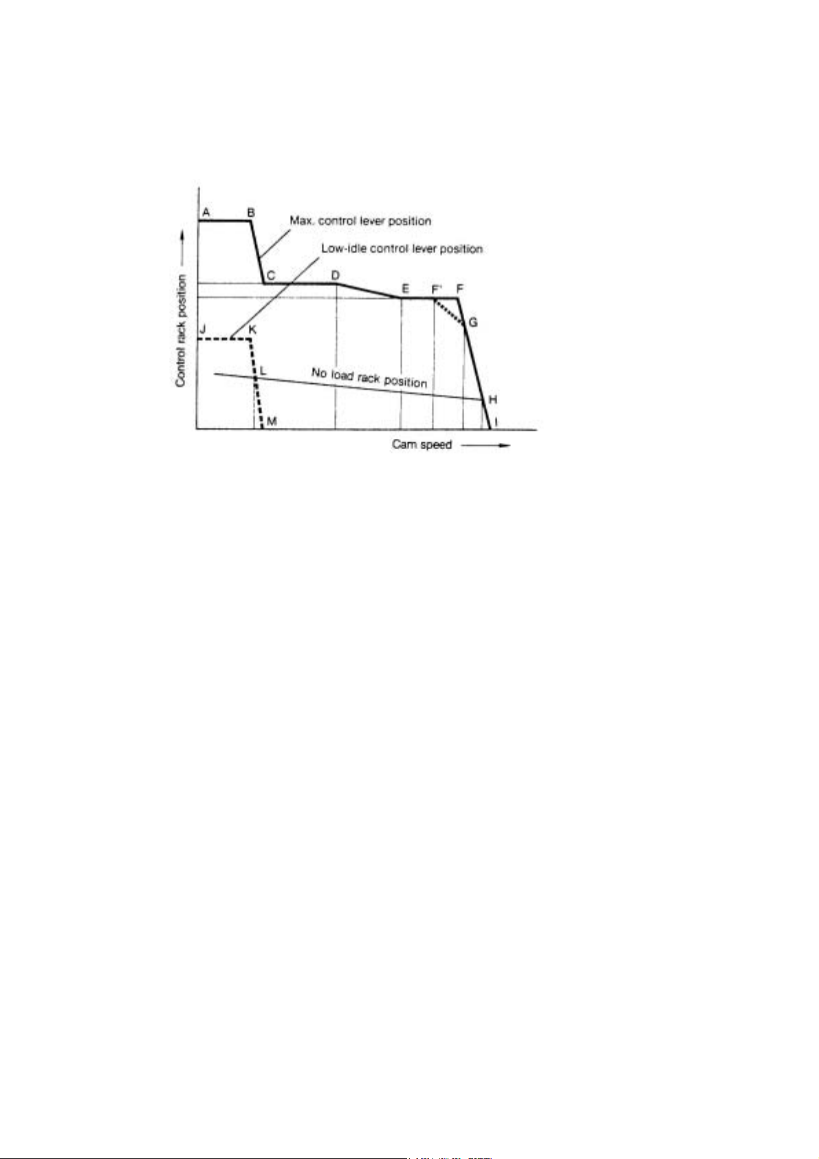
2.4.2.2. Function of Governor
(1) Function of governor
Following is a representation of the movement characteristics of the control rack at respective speeds,when the speed
rise from 0,with the governor control lever at the maximum speed position:
A-B : Fuel volume condition during starting. Volume is controlled by excess fuel spring.
B-C : The rack moves towards decrease after engine starts and speed increase as the load of the excess fuel spring is
overcome by the centrifugal force of the governor weight.
C-D : High torque at low speed is developed by increasing fuel injection volume equivalent to the angleich stroke.
D-E : Condition when the thrust force exceeds that of the angleich spring force on the bottom of the tension lever and it
gradually pushes the rack to decrease fuel when engine speed increases.
E-F : Condition when both right and left ends of the shifter come in contact with the sleeve and the bottom of the tension
lever, and the control rack is kept at the normal position by the stopper.(max.injection volume position on models not
equipped with an angleich spring)
F : Point when governor starts to take effect.
This is the rated output of the engine.
F’ : Point when governor start to take effect on models with torque spring.
G : Continuous rating point(usually 85-90% injection volume of F point).
H : No load max.speed
L : Low-idle position
11
Page 17
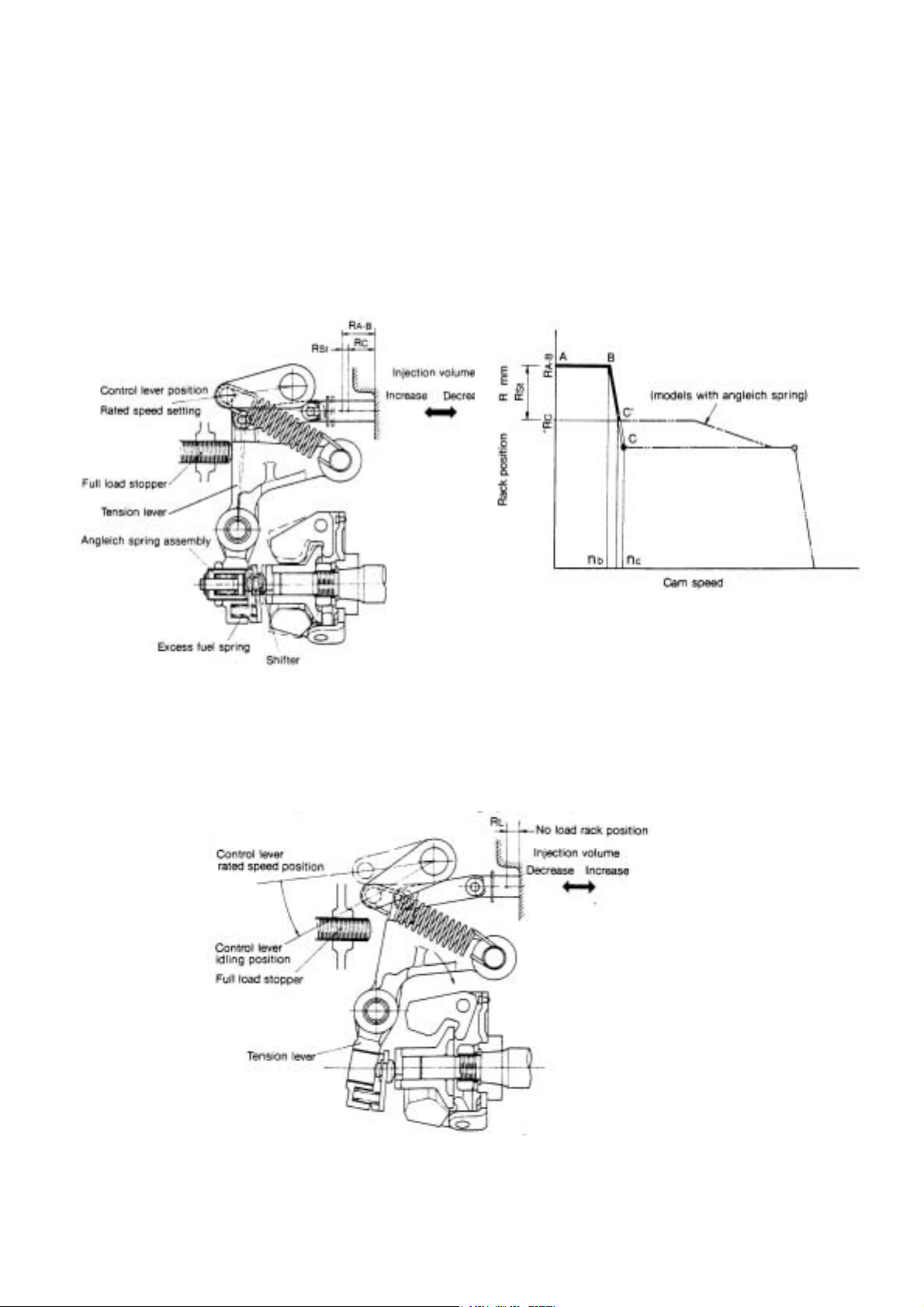
(2) Starting control
Moving the control lever to the max.speed position pulls the governor spring, and moves the tension lever until it comes in
contact with the control stopper.
When this is done,the excess fuel spring provided in between the tension lever and governor lever holds the control rack
at the maximum starting injection volume position R
After the engine is started, the excess fuel spring is compressed when the centrifugal force of the governor weight
overcomes the set of the excess fuel spring as speed exceeds N
spring ) or B to C(on models without angleich spring ). The rack reaches the position of R
tension lever are interlocked.
A-B.
b, speed goes from B to C' (on models with angleich
c where the governor lever and
(3) Idling
When the control lever is returned to the idling position after the engine is started. the governor spring tension decreases
and the tension lever descends clockwise, and the governor weight load keeps the governor spring and the excess fuel
spring load in equilibrium to maintain idling speed at (R
L).
12
Page 18
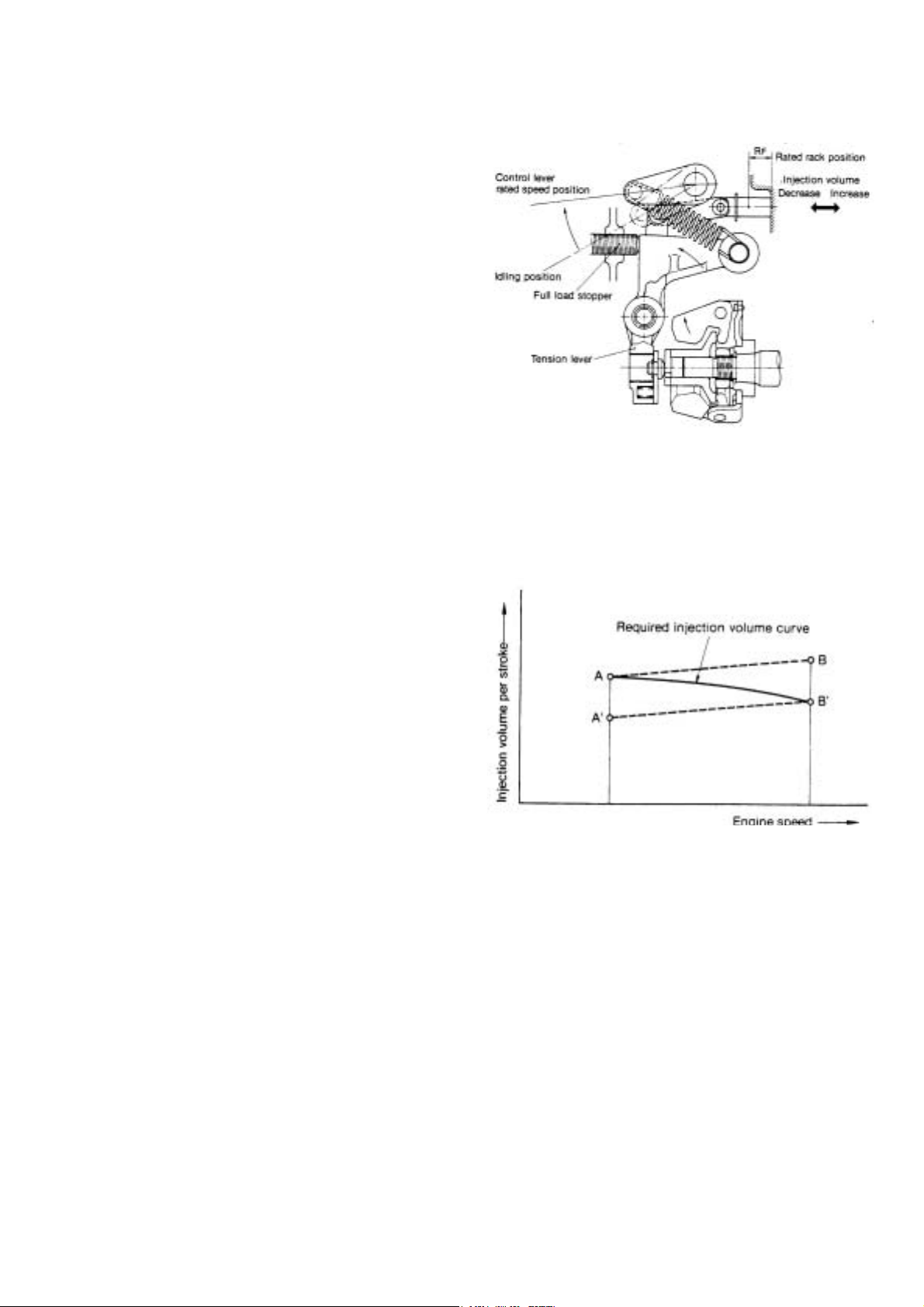
(4) Max speed
The angle of the control lever is set at determined
engine speed. The governor keeps engine speed
constant by adjusting sped when load changes.
For example, if the operator moves the control lever
with the link from the idling position to max. Output,
governor spring tension increases, the tension lever is
pulled until it comes in contact with the full load stopper,
the movement of the governor lever is transmitted
to the control rack via the link, maintaining the full load
rack position, and engine sped increase until the
governor weight thrust load and governor spring
tension come into equilibrium at full load max. Speed.
(5) Necessity and function of angleich
The governor must satisfy the required injection curves
represented in the diagram below in order to obtain
sufficient output at low speed, and not emit black
smoke at high speed. the angleich spring was devised
to provide for maxim um torque at low sped by setting
injection volume at point A, and shifting injection
volume to point B' at high engine speed.
13
Page 19
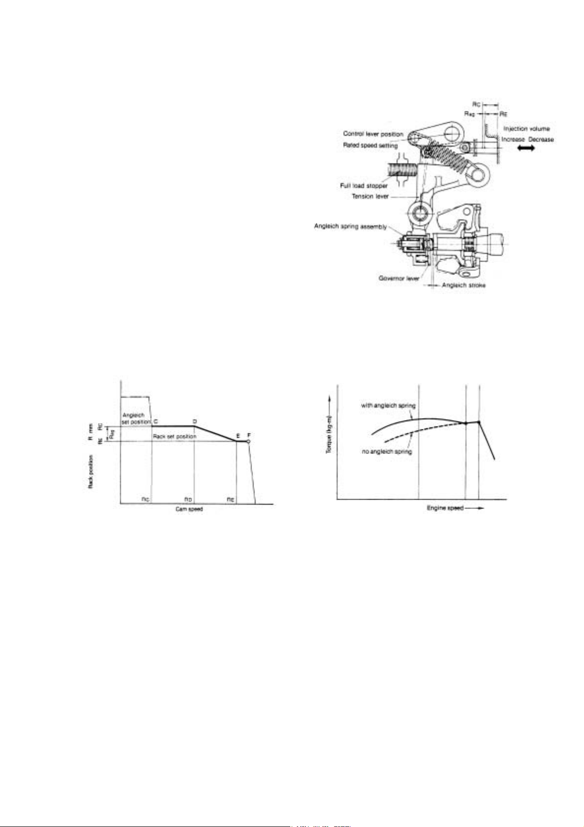
The angleich spring is mounted to the part of the
tension lever (however some engine are not equipped
with an angleich spring depending on usage and speed
range utilized).
When engine speed is low, the governor weight cannot
compress the angleich spring as the angleich spring
load is lager than the governor weight, thrust load, and
the control rack is held at a position (R
injection volume.
Furthermore, as engine speed rise, the angleich spring
is gradually compressed as governor weight thrust load
increases and exceeds angleich load, before high
speed control is effected. When the governor lever and
the bottom of the tension lever come into contact (end
of angleich stroke), injection volume is reduced by that
amount, and the rack reaches the rated position (R
c) to increase
E).
14
Page 20
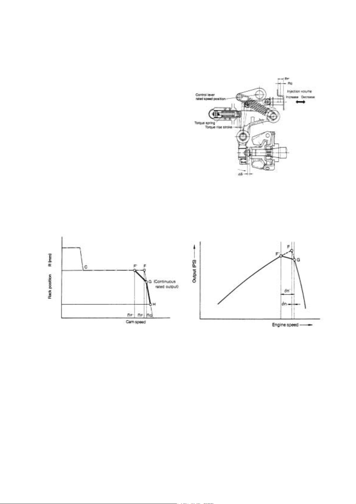
(6) Necessity of torque spring and function
Engines used in construction machinery are subjected
to sudden loads which cause a decrease in speed and
sometimes results in stopping of the engine. A torque
spring is provided to move the control rack towards
injection volume increase when engine speed decrease,
to increase torque to withstand overloads, and in turn
prevent the engine from stopping.
The governor control lever is fixed at point G in the
diagram below, the continuous rated output position.
At this time,when engine is loaded, the tension lever
encompasses the torque spring, the control rack comes
away from full load stopper, and fluctuates between G
and H according to engine load.
When the load on the engine exceeds the continuous
rated output, speed decrease, governor spring tension
exceeds the governor weight thrust load and
overcomes the torque spring set load. The tension lever
then gradually causes the control rack to move towards
injection volume increase via the governor lever and
link, and the torque rise stroke ends when the control
rack reaches F'.
The torque spring thus provides for increasing of injection volume when speed decrease, to increase engine torque and in
turn prevent engine stopping due to sudden increases in load, and also provide for strong engine output characteristics.
15
Page 21

(7) No load max. speed
When the load decreases from full load max. speed
and engine speed further increase, the increased thrust
load of the governor weight acting on the governor
spring through the tension lever exceeds the set load of
the spring, the tension lever and governor lever
descend clockwise, the control rack is pushed to the no
load injection volume position (RH), and the engine is
operated at no load max. Speed.
When the engine is being used at partial load, the
governor spring functions in the same way at a lower
speed (i, i'-j) as for full load max. Speed, as the
governor spring set load is smaller.
(8) Stopping engine
The engine stops when you turn the governor control lever all the way towards stop.
On engine equipped with a stop device, the engine can be stopped by moving the control rack to the stop position,
regardless of the control lever position.
16
Page 22

234
2
3
2.4.3. Delivery Part
Delivery Ports and Cylinder Number
Cylinder No.
Port No.
Injection Order
4MP2, 4MP4
Flywheel side
1 2 3 4
B A C D
2 1 3 4
Driving side
1
Cylinder No.
Port No.
Injection Order
3MP2
1 2 3
B A C
2 1 3
Flywheel side
Driving side
1
17
Page 23

2.5. Function of Component
2.5.1. F.O. Feed Pump
The FO feed pump feeds fuel oil from the fuel tank to the fuel injection pump via the water separator and fuel filter.
The trochoid FO feed pump, installed on the fuel injection pump side, is driven by the fuel camshaft via the bevel gear.
This feed pump can feed high pressure fuel oil into the FO injection pump, but while the fuel oil inside the piping is empty
due to shortage of gases, etc., the pump’s self-feeding performance is low. Accordingly, the manual priming pump with
FO filter or solenoid pre-feed pump is used together. The feed pump failure causes the delivery pressure and volume to
drop. This, in turn, shortens the service life of the fuel injection pump and causes the pump to become faulty.
Replace the feed pump assembly after 10,000 hours’ use as a standard.
FO feed pump
① Pump case
② Pump cover
③ Inner rotor
④ Outer rotor
⑤ Shaft
⑥ Molded ring
⑦ Oil seal
⑧ Bevel gear
⑩ Drive pin
⑪ Relief valve
⑫ Spring
⑬ Seal washer
⑭ Relief plug
⑮ Bolt
⑯ C-ring
⑰ Bush
⑱ Thrust washer
⑲ Washer
18
Page 24

2.5.1.1. Specifications of F.O. Feed Pump
Suction Head
(kPa)
Std. Delivery Pressure
(MPa)
Std. Delivery Volume
(cm
YPD-MP2 YPD-MP4
0.4-0.5 0.6-0.7
3
/min)
Pressure & delivery volume figures at conditions below:
Conditions:
Outlet orifice dia. :φ0.7mm
F.O. grade : ISO 8217
Revolutions : 1000min
-1
F.O. temp. : 40 degC (104 degF)
2.5.1.2. Inspection of F.O. Feed Pump
-10
500 600
(1) Check for the abnormal flaws and chipping on the bevel gear face. If found to be abnormal, replace the whole feed pump
assembly.
(2) Check for the abnormal flaws or wear on the face contacting with the pump case, pump cover, inner rotor and outer rotor.
If wear exceeds 0.1mm, replace the whole feed pump assembly.
(3) Check for the abnormal wear of the shaft and oil seal moving area. If wear exceeds 0.05mm in depth, replace the whole
feed pump assembly.
(4) When no abnormality was found, just replace the molded ring and seal washer and re-assemble.
(5) After install the fuel injection pump, operate the fuel injection pump to check that no oil leaks from each part.
19
Page 25

2.6. Timer Mechanism
When the engine is used in a wide range from low to high speeds, it is necessary to change the fuel injection timing
according to the engine speeds for always keeping the optimum firing timing. It is also necessary to optimize the
injection timing for reducing noise and exhaust gas emissions.
This pump has the timer mechanism for revolutions, load and cold starting.
2.6.1. Structure and Functions
The engine speed timer is the mechanical timer which uses the oil leakage from the small diameter sub spill port installed
slightly upper side of the main spill port of the jerk pump. When the engine speed is high, pressure rises before oil leaks
from the small diameter port and injection is started. But when the engine speed is low, pressure does not rise until the
port blocked by the plunger and the injection start is delays. Usually, the lower the engine speed, further the injection
timing advances. But this engine speed timer prevents the injection timing from advancing during the low engine speed
ranges and thus the noise and Nox. emissions can be controlled.
The fewer the injection amount, the earlier the load timer causes the main port to close by the plunger’s upper lead for
advancing the injection timing. This feature is instrumental in preventing misfire or emission of bluish white smoke during
low load operation.
The cold start timer causes the sub port to be blocked only under cold temperatures for accelerating injection timing and
facilitating in cold starting. The timer houses the thermo element and cooling water circulates around the temperature
sensing section. The thermo-element senses the coolant temperature for adjusting the control piston. The sub-port is
blocked when the temperature is lower than the set temperature and the pressure is raised earlier than in the normal
temperature for advancing the injection timing. When the temperature exceeds the set temperature, the sub-port is
opened and the regular injection characteristics are recovered.
Hydraulic control device of injection timing
Hydraulic control device of injection timing
(Speed timer,Load timer,Cold start timer)
(Speed timer,Load timer,Cold start timer)
Required characteristics
Advance
g
n
i
m
i
T
n
o
i
t
c
e
j
n
I
Retard
Required characteristics
Improving cold startability
At cold start
At no load
At full load
Reduction of noise & NOx
Reduction of white smoke
Pump speed
B : Sub Lead
Main Port
Main Lead
Rated
A :Sub Port
Timing Control
Device
Coolant
.
C : Thermo
-element
Piston
Barrel
Plunger
20
Page 26

2.7. C.S.D.(Cold Start Device)
2.7.1. Cold Starting Advancer
Purpose
In order to facilitate easy engine starting under cold temperatures, the advancer senses the cooling water temperature for
advancing the fuel injection timing.
2.7.1.1. Structure & Function
At normal operating
Sub-port
is opened
Termo-elementt
Main port
Sub port
Fuel IN
Plunger barrel
Plunger
Fuel gallery
Spring
When the coolant temperature is higher than specified
value, the thermo-element keeps expanding and the subport is opened.
At cold starting
Engine coolant
Sub-port
is closed
Piston
Fuel IN
When the coolant temperature is lower than specified
value, the thermo-element keeps shrinking and the subport is closed by piston.
21
Page 27

3. Disassembly ,Reassembly
and Inspection
3.1. Disassembly
Disassembled parts must be put aside in order.
Wash them before reassembly.
3.1.1. Separating the pump body from the
governor body
Install the pump body to the disassembly table.
Remove the link lifter fix bolt.
Turn the link lifter plate counterclockwise.
Rotating the link lifter will move the inside link
upward/downward, so the control rack may be
engaged/disengaged.
Remove the bolt fixing the pump and governor bodies.
Separate the governor from the pump body.
The pump body separated from t he governor body
Link insertion window
22
Page 28

t
3.1.2. Separating the governor weight CMP
Providing whirl-stop to the camshaft
Disassembling the delivery valve
Remove the holder, (delivery).
Remove the delivery valve and gasket.
Example of whirl-stop
Remove the nut, (governor support).
3.1.3. Disassembling the hydraulic head
Disassembling the hydraulic head
Delivery valve parts disassembled. (Take care no
to mix these with other parts on reassembly.
Reassemble these to the original port as a set.)
Remove the joint, (FO inlet pipe).
Remove the delivery valve and gasket.
Remove gasket
23
Page 29

Remove the distribution shaft.
Removed parts must be stored in the cleaning oil sump.
Remove the plug and gasket, (barrel).
Remove the holder and gasket, (timer)
Remove the plug, (accumulator).
Make sure that the seal washer remains on the plug.
Remove the plug, (C.W.) and the joint, (C.W.)
Parts disassembled.
Remove the thermo element.
24
Page 30

3.1.4. Separating hydraulic head CMP
Remove the hydraulic head CMP fixing bolt.
3.1.5. Separating the cam shaft
Remove the joint, (distribution shaft).
Remove the feed pump.
A
Remove the hydraulic head CMP.
Remove the packing.
Do not loosen two bolts (A)
.
O-ring
Make sure that two O-rings are free from
damages.
Remove the removal stop, (transmission shaft) fastening bolt.
25
Page 31

Remove the whirl-stop, (tappet).
Take out the tappet.
Lift the transmission shaft slightly by your hand.
Align the camshaft’s key groove with the embossed mark on
the body.
Tappet disassembled and FIC adjust shim.
Remove the retainer, (bearing) fastening bolt.
Lift the transmission shaft a little and pull out the camshaft.
Camshaft extracted
Remove the retainer, (bearing).
Remove the transmission shaft CMP.
26
Page 32

g
p
Remove the transmission shaft CMP.
3.1.6. Disassembling the hydraulic head CMP
Compress the plunger spring and remove the
spring retainer, (B).
While compressing the plunger spring using special service
tool, remove spring retainer B.
S
ring retainer B.
Plun
er SP seat extractor
Hydraulic head
Remove the rack return spring.
Remove the rack guide.
Remove the spring retainer.
Remove the control sleeve.
Cleaning oil sump
Remove the plunger.
Parts removed from hydraulic head CMP
Disassembled parts must be separately stored in the cleaning
oil sump.
Cleaning oil sump
Remove the rack guide fastening bolt.
27
Page 33

3.2. Disassembling the Governor
Remove the lock nut, (Control lever).
Remove the regulator lever.
Removed governor lever shaft
Take out the governor lever CMP.
Remove the shim.
Remove the removal stop, (governor lever shaft) fixing bolt.
Remove the removal stop, (governor lever shaft).
Remove the spring.
Pull out the governor lever shaft.
28
Page 34

r
f
r
f
r
3.3. Reassembly
3.3.1. Re-assembling the hydraulic head
Install the plunger.
Upper lead
Ball
Sub-lead
Identification marking
! Note that the positional relationship of the uppe
lead and sub-lead of the plunger and the ball o
the control sleeve is as shown below. (Plunge
identification marking (such as "W4") and the ball
of the control sleeve are oriented in the same
direction.)
! Be careful that the plunger is NOT inserted
upside down.
Install the control sleeve and spring retainer.
Install the rack guide.
Rack guide
Control sleeve
Rack auxiliary SP
Distribution shaft sleeve
L
Upper spring retainer
Attaching rack and rack guide
! When installing rack guide, push it against the
distribution shaft sleeve and upper spring retainer so
that the rack is in parallel with the direction o
camshaft. (T = 3 to 4 N•m)
! Movable range of rack is to be equal to or large
than ±7 mm.
! Fix the rack at the position of L = 25, and measure
the effective stroke and sub-step (overflow stroke) to
check that they are within the standards (Refer to
attached drawing 1.)
! The rack must not separate from the ball of the
control sleeve within the movable range.
! Fix the plunger with a jig and measure the total
backlash. (To be equal to or less than 0.2 mm)
! The load of rack auxiliary SP must be able to return
the rack from the maximum decreased position to
the maximum increased position).
Rack
29
Page 35

A
Install the rack guide fastening bolt.
Tightening Torque : 3.9-4.9 N-m
Spring retainer (B).
Spring.
3.3.2. Re-assembling Cam Shaft
Install the transmission shaft CMP.
Install the plunger spring and spring retainer (B).
ttaching transmission shaft CMP
! Apply molybdenum disulfide to the shaft section.
! Check that the transmission shaft rotates
Install the camshaft.
30
Page 36

A
A
t
k
ttaching camshaft
!
pply molybdenum disulfide to the bushing or the
bearing.
! Insert the camshaft into the pump body with
transmission shaft CMP at the lowered position
(gear B touching the pump body).
Install the camshaft.
Tightening Torque : 8-10 N-m
! Be careful that the cam and gear B do not interfere
with each other.
! (Especially for 4 cylinder engine, note that the
phase in which the cam passes is limited.)
! The shaft can be inserted with the key of the
driving side press-fitted to the camshaft.
Be careful not to damage the camshaft bushing.
Checking backlash
! Rotate camshaft to check that transmission shaf
rotates smoothly.
! Fix transmission shaft from upper surface of the
housing, and turn the camshaft to check the backlash.
Backlash must be in the range from 0.2 to 1.5 degree.
Note: When measuring at the position of camshaft
driving side key (at the center of the key as shown below),
the displacement must be in the range from 0.03 to 0.25.
Rack plug
Tighten the rack plug. (If rac
plug has been removed.)
Tightening Torque : 79-84 N-m
Position the transmission shoe of the
transmission shaft CMP as shown in the
illustration.
31
Page 37

Position the camshaft key groove as shown in the
illustration.
Engagement of gears
・ With the phase of camshaft and collar of transmission shaft set in the direction as shown below, engage gears
A and B with each other. (Check that the match mark of gear B and the mark of gear A shown below are
aligned with each other by looking through the feed pump installation hole.)
・ When inserting the stopper pin, do not raise the transmission shaft excessively, or the gears will be
disengaged. (Check the engagement again after inserting the stopper pin.)
・ The positions of the collars of transmission shaft are not limited only if either one is at the top or bottom as
shown.
Install the removal stop, (transmission shaft).
Fasten the removal stop, (transmission shaft).
Tightening Torque : 8-10 N-m
32
Page 38

A
t
t
(
φ
)
Whirl-stop groove
Install the tappet.
Direct the tappet’s whirl-stop groove as shown in the
illustration.
ssembling tappets
! Insert tappet into the pump body with the sli
directed toward the lock side, and attach the
•
tappet lock. (T = 4 to 5 N
! Turn the camshaft to check that the tappe
moves up and down smoothly.
m)
Fasten the nut, (governor support), (and provide the whirl-stop
to the cam shaft.)
Tightening Torque : 79 - 84 N-m
Install the feed pump.
Install the whirl-stop, (tappet).
Tighten the tappet, while moving it upward and
downward.
Identification hole
3, depth 2 mm
Identification of feed pump
Spec.
General
purpose
TK Provided
φ3 identification
hole
Not provided
Install the governor weight CMP and nut, (governor support).
33
Note that the identification hole can be seen only when
looking from obliquely above because it is located on the
pump case side.
Page 39

y
A
t
f
A
r
f
3.3.3. Install the hydraulic head CMP.
Install the hydraulic head CMP.
Insert the two positioning pins. Be sure not to confuse
packing front with rear surface. (Align them with holes
on the body.)
Install the joint, (transmission shaft).
Assemble the FIC adjust shim inside the tappet.
Installing H head
!
ssemble shims with an appropriate thickness tha
corresponds to the measurement of the bottom
clearance (refer to attached drawing 3).
! Temporarily tighten the hexagon socket head bolts
evenly in the order as shown below until the surfaces o
H head and pump body contact with each other, and
subsequently tighten to the specified torque in the same
order.
fter assembling H head, check the top clearance
!
again.
! After assembling H head, push the rack from governo
side to check that the rack is returned with the force o
rack auxiliary SP.
! When reassembling H head, be sure to replace the
head packing with new one.
Install the hydraulic head CMP.
While hand pressing the hydraulic head, temporaril
tighten the tightening bolts. Then, tighten them
with specified torque.
Install the hydraulic head CMP fastening bolt.
Important
Tightening Torque : 18-22 N-m
Tighten the bolts in diagonal order, while checking the
torque with torque meter.
34
Page 40

A
t
f
f
p
g
A
p
g
A
p
g
p
g
Measure the plunger top position.
Bottle clearance adjustment should refer to Page 59.
3.3.4. Assembling the Hydraulic Head
Install the distribution shaft.
Inserting distribution shaft
・ Insert distribution shaft so that the directional
relationship between the shaft and camshaft is as
shown below (Do not assemble upside down).
・ Use the following drawing simply as a reference
because the component can be inserted in either o
two orientations.
・ Insert the component securely into the distribution
shaft joint until it is sunk below the end surface o
the distribution shaft sleeve.
Direction of fixed flange (camshaft keyway)
(As viewed from driving side)
Install the accumulator.
ttaching accumulator
! Be sure to install the piston in the correc
direction.
! Make sure that the piston can slide smoothly.
Install the spring, (accumulator).
Camshaft keyway
side
eratin
O
Flange cutout
Direction of distribution shaft longitudinal
groove
(As viewed from upper side
Distribution shaft longitudinal groove,
cut off surface
Governor side
side
Upper side
Lower side
side
eratin
nti-o
side
eratin
O
Driving side
eratin
nti-o
Install the plug with new seal washer, (accumulator).
35
Page 41

p
g
p
Install the plug, (distribution shaft).
Fasten the plug, (distribution shaft).
Tightening Torque : 10-15 N-m
Install the new packing, (delivery valve seat).
Install the delivery valve CMP.
Holder(delivery
Spring(delivery
Valve(delivery
Returnvalve (φ2)
ring seat(return valve
S
Returns
rin
Seat(delivery
Packing(delivery
Install the plug with new copper packing, (barrel).
Fasten the plug, (barrel).
Tightening Torque : 30-35 N-m
Install the spring, (delivery).
Install the holder, (delivery).
Tightening Torque : 40-45 N-m
36
Page 42

g
Install the new packing, (timer).
Install the holder with new O-ring, (timer).
Thermo-element
Spring
O-ring P15
(Hardness 90
O-ring JASO 1011
* JASO : Japanese Automobile Standard
C.W.plug
Seal washer
O-ring P14
Piston(thermo-e
lement)
O-ring(JASO 1020)
Timer holder
O-ring(JASO 1020)
Timer piston
Damper ring
Timer packing
! Do not forget to assemble the timer packing,
(at holder bottom).
! Do not forget to assemble the damper ring.
! Take care not to use O-rings with
inappropriate sizes.
Check that the timer piston moves smoothly in
the timer holder hole (clearance: 4-8 micron m).
Fasten the holder, (timer).
Install the thermo-element with new O-ring.
! Before installing the thermo-element, press
down the piston with the timer holder bein
installed to the head, (T=40-45N.m), and
check that the piston returns up through the
spring load.
! The standard thermo-element release
temperature shall be 5-8 degC(41-46.4 degF).
(Thermo-element released at 15-18 degC (59-
64.4 degF) is available as option.
Take care not to mistake the specifications:
see diagram below.)
! Do not pull out the piston housed in the
! Do not tighten the thermo-element with
Thermo-element for 15~18 degC
thermo-element manually. If it is extracted
manually, discard it since the re-use of the
piston is no longer possible.
excessive tightening torque, (T=30-35N.m).
Identification groove
! Do not tighten t he cooling water plug with
excessive tightening torque, (T=22-25N.m).
! Take care not to catch impurities in the seal
washer.
37
Page 43

Fasten the thermo-element.
Tightening Torque : 30-35 N-m
F.O. valbe
return pipe
F.O. outlet
Cooling water
F.O. inlet
Install the joint, (C.W), and he plug, (C.W.)
Assemble the seal washers, taking care not the washer
stride over steps. (One seal washer is required for
respective upper and lower portions.)
Fasten the plug, (C.W.)
Install the joint, (FO inlet).
Installation position of Joints
Direction of pipe depends on respective specifications.
Install the joint, (overflow) and the joint, (overflow).
38
Page 44

3.4. Re-assembling the Governor
Governor Body Parts
Install the shim to the shaft, (control lever).
Install the regulator lever.
Governor Lever CMP End Float Adjust Shim
Pierce the governor lever CMP and shim through the governor
lever shaft and assemble.
Measure the side clearance of the tension lever with
thickness gauge.
Standard: 0.3 to 0.6 mm (adjusting with shim)
Pierce the spring, (control lever) through the lock nut, (control
lever) and fasten it to the thread of the shaft, (control lever).
Fasten the nut, (control lever).
Tightening Torque : 19.6-24.5 N-m
Fit the governor lever shaft with the removal stop, (governor
lever shaft) and fasten the removal stop bolt.
Measure the side clearance with thickness gauge.
Standard: 0.3 to 0.6 mm (adjusting with shim)
39
Page 45

y
A
3.5. Combining Governor and
Pump Bodies
Install the new packing.
Do not confuse front with rear surface. Assemble it,
while aligning bolt holes with those on the body.
Rack
Turn the link lifter plate counterclockwise. and install the
governor body to the pump bodies
Link
a) During assembl
Link lifter
ttaching governor CMP
・ Be careful not to bend or damage the governor case packing (GRC). (It is not reusable. If it
sticks to the packing surface, remove it without giving damage to the surface of the packing.)
・ Direct the link lifter as shown in Fig. a) shown below, where the semicircular section is
positioned at the lower side, and bring governor CMP to the pump body until the link comes
into contact with the rack.
At this time, be careful that the link does not hit the pump body. (If the link hit the pump body
severely, check that the link is not bent or deformed.)
・ Direct the link lifter as shown in Fig. b) shown below, where the semicircular section is
positioned at the upper side, and engage the rack and the link with each other.
At this time, if it is difficult to engage the rack and the link with each other, assemble them while
pushing the governor lever to the decreasing side (when mechanical governor is used).
・ After putting the link lifter in the state shown in Fig. b), pull the governor CMP a little to check
that the link and rack are engaged with each other. (Be sure not to pull governor CMP
excessively).
(If the barrel plug is not installed yet, the following method can be used to check the plunger
rotation.
Mechanical governor: Push the governor lever to the decreasing side through the solenoid
attaching hole.
New ECO governor: Push the rack to the increasing side through the rack inspection port.)
・ Be sure to tighten the link lifter securing bolt. (T = 8 to 10 N - m)
b) During operation
40
Page 46

Insert the governor link into the link hole of the pump body.
Fit the link lifter to the installation hole and fasten the bolt.
Install the governor case cover to the case.
This completes reassembly of the pump.
Pull the governor assembly slightly to check that the link is
engaging securely.
Combine Governor and Pump Bodies
Install the new O-ring to the stop solenoid and assemble them
to the governor case.
Tightening Torque : 7.8-9.8 N-m
nstall a new packing, (governor case cover) to the case.
41
Page 47

4. Adjustment of Fuel Injection Pump and Governor
Adjust the fuel injection pump after you have completed reassembly. The pump itself must be readjusted with a special
pump tester when you have replaced major parts such as the plunger assembly, roller guide assembly, fuel camshaft, etc.
Procure a pump tester like the one illustrated below.
4.1. Preparations
Prepare for adjustment of the fuel injection pump as follows:
(1) Adjusting nozzle assembly and inspection of injection starting pressure.
(2) Adjusting injection pipe.
(3) Mount the fuel injection pump on the pump tester platform.
Adjusting nozzle type
Injection starting pressure
Inner dia./outer dia. × length
Minimum bending radius 25
Mpa (kgf/cm2)
YDN-12SD12
16.2 – 17.2(165 – 175)
mm
Ф2.0/Ф6.0 × 600
42
Page 48

(4) Remove the plug in the oil fill hole on the top of the governor case, and fill the pump with about 200cc of pump oil or engine
oil.
(5) Complete fuel oil piping and operate the pump tester to purge the line of air.
2
(6) Set the pressure of oil fed from pump tester to injection pump at 19.6-29.4kPa(0.2-0.3kgf/cm
) ,temp. at 40±2 degC(104±
3.6 degF)
43
Page 49

A
A
g
4.2. Bottom clearance adjustment(Fuel Injection Timing)
1. The Fuel Injection Timing of MP-pump is made by means of
adjusting the bottom clearance of the Cam ie. adjustment of the
Pre-stroke of the plunger , as follows.
2. The adjustment of the clearance shall be made at cam-top
position in order to get the reliable and easier method.
Therefore herein after we will mention that “The adjustment of
the bottoms clearance (of the Cam)”.
3. First of all , put the JIG of the bottom clearance measurement
on the standard gauge(W/”A”- measurement). Then set the
O-point of the dial gauge.
4. Next adjust the clearance by shims into the standard after
measuring the bottom clearance A* with JIG (Dial gauge)(Refer
to the attached sheet)*Measurement between upper surface of
the Barrel and upper surface of the plunger at Cam bottom
position
ottom clearance gauge
Dial gauge
Barrel
Bottom clearance gau
Plunger
Shim
44
Page 50

4.2.1. The bottom clearance adjusting value and the Cam classification
MP2
MP4
Shape of cam shaft end
Cam speed 3 cylinder 4 cylinder
1.1 m/s 158552-51020 158553-51020 25.5±0.05 1.3
1.3 m/s 158552-51030 158553-51030 25.9±0.05 0.9
1.7 m/s 158552-51040 158553-51040 26.3±0.05 0.8
1.8 m/s 123907-51040
2.1 m/s
2.3m/s
Cam shaft
129906-51040
129907-51040
Cam Speed
MP2 MP4
1.1m/s 2.3m/s
1.3m/s 2.1m/s
1.7m/s 1.8m/s
Plunger bottom
Clearance (dimension: A)
(mm)
25.55±0.05 1.05
Standard shim
thickness (mm)
45
Page 51

4.3. Adjustment of Governor
4.3.1. Adjustment of No Load Max. Engine Speed
Set the engine speed at the no load max. speed. Pull the regulator
lever and adjust the max. speed limit bolt to obtain the specified
injection amount. Fasten the nut after completing the adjustment.
4.3.2. Adjustment of Fuel Limit Bolt
① The MP2 pump has the lift adjustment FO limiter as a standard
equipment. Screw in the lift adjustment screw fully, then return
the screw by 0.5 turns and fasten the screw with the lock nut. (In
the specifications where no torque control spring is used, keep the
lift adjustment screw completely free.)
② Set the pump speed at the rated speed and move the regulator
lever until it contacts the maximum speed limit bolt.
③ Check that the amount being injected exceeds the rated injection
amount, screw in the fuel limit bolt and adjust the injection amount.
4.3.3. Adjustment of Torque-Rise Point
The Torque-Rise adjustment comprises the FO limiter (torque spring) and the torque control spring.
① Set the pump speed at the Torque-Rise speed and leave the
regulator lever at the position in 2 above.
② When both of the FO limiter and torque control spring are used:
Adjustable lift torque spring
! Screw in the torque control assembly, adjust to obtain the
specified injection amount and fasten the lock nut.
③ Specifications of Only the FO Limiter
! Screw in lift limit bolt of the FO limiter, adjust to obtain the
specified injection amount and fasten the lock nut.
46
Page 52

4.3.4. Adjustment of Reverse Angleich
In the case of the governor with reverse angleich mechanism, use the reverse angleich spring
in the assembled state.
Adjustment of Reverse Angleich
Make adjustment of reverse angleich after completing the following processes:
① Shift the control lever to the full load position, and maintain the fuel injection pump revolution to the
② In this condition, remove the governor rear cover, and screw the reverse angleich assembly into
③ Tighten the lock nut with specified tightening torque, and attach the governor rear cover.
● Adjustment of fuel volume limiter bolt
● Adjustment of no-load max, and min. revolutions limiter bolt
specified reverse angleich control revolution number (N
the threaded portion of the tension lever until it hits the reverse angleich lever. If screwing it in
additionally, the reverse angleich lever will shift in the direction of fuel reduction. Screw and set it to
the position of the specified injection quantity (R
Lock Nut Tightening Torque 24.5-29.4(2.5-3.0)
6).
6).
N-m (kgf-m)
④ Again, increase the revolution of the fuel injection pump to the rated revolution speed (N1), check
that the control rack will change the position of the reverse angleich stroke smoothly, and confirm
that the rack position (R
1) and injection volume are within the specified limits.
47
Page 53

4.3.5. Adjustment of Staring Injection Amount
① Set the engine speed at the starting injection amount adjust
speed and leave the regulator lever at the position in 2
above.
② Screw in the starting injection amount adjust bolt and adjust
it to obtain the specified injection amount.
③ Set the pump speed at 50 min-1 and check that the amount
exceeding the specifications is being injected.
4.3.6. Checking the Injection Stop
Leave the regulator lever at the position as before.
① Checking the Injection Stop: Set the pump speed at the
speed 50min-1 higher than the no load max. speed, and
check that the injection amount reduces to zero.
② Checking the Stopping: Set the pump speed at the rated
speed, turn off the stop solenoid and check that the
injection amount reduces to zero.
48
Page 54

5. Fuel injection Nozzle
When fuel 0il pumped by the fuel injection pump reaches the injection nozzle,it pushes up the nozzle valve(held down by
spring),and is injected into the combustion chamber at high pressure.
The fuel is atomized by the nozzle to mix uniformly with the air in the combustion chamber. How well the fuel is mixed with
high temperature air directly affects combustion efficiency,engine Performance and fuel economy.
Accordingly, the fuel injection nozzles must be kept in top condition to maintain performance and operating efficiency.
5.1. Functioning of fuel injection nozzle
Fuel from the fuel injection pump passes through the oil port in the nozzle holder and enters the nozzle body reservoir.
When oil reaches the specified pressure,it pushes up the nozzle valve(held by the nozzle spring),and is injected
through the small hole on the tip of the nozzle body.
The nozzle valve is automatically pushed down by the nozzle spring and closed after fuel is injected.
Oil that leaks from between the nozzle valve and nozzle body goes from the hole on top of the nozzle spring through the oil
leakage fitting and back into the fuel tank.
Adjustment of injection starting pressure is effected with the adjusting shims.
5.2. Type/construction of fuel injection nozzle
There are two types of fuel injection nozzles. Direct injection engines are equipped with the hole type, and indirect injection
engines with the pintle type.
The YPD-MP fuel injection pump is designed for use with both direct and indirect injection engines. The hole type/pintle
type of fuel injection nozzle are used according to the engine type.
Hole type fuel injection nozzle
Nozzle opening
pressure
Nozzle angle deg. 162 159
No. of nozzles×dia.
Identification No.
(Nozzle type)
F.O. return pipe joint
Nozzle holder
MPa
(kgf/cm
mm
21.6
2
)
162P165VAE1 159P175VAD1
+1.0 (+10)
0
5×0.16 5×0.17
(220)
(0)
Nozzle spring
Nozzle spring seat
49
Page 55

Nozzle body identification number
The type of nozzle can be determined from the number
inscribed on the outside of the nozzle body.
1)Hole type fuel injection nozzles
5.3. Fuel injection nozzle disassembly
Note:
1. Disassemble fuel injection nozzle in a clean area as for fuel injection pump.
2. When disassembling more than one fuel injection nozzle, keep the parts for each injection nozzle separate for each
cylinder (i.e. the nozzle for cylinder 1 must be remounted in cylinder 1).
(1) When removing the injection nozzle from the cylinder head, remove the high pressure fuel pipe, fuel leakage pipe, etc.,
the injection nozzle retainer nut,and then the fuel injection nozzle.
(2) Put the nozzle in a vise
NOTE: Use the special nozzle holder for the hole type injection nozzle so that the high pressure mounting threads are
not damaged.
50
Page 56

(3)Remove the nozzle nut
NOTE: Use a special box spanner for the hole type (the thickness of the two nozzle nuts is 15mm(0.5906in.)).
(4) Remove the inner parts
NOTE: Be careful not to loosen the spring seat, adjusting shims or other small parts.
5.4. Fuel injection nozzle inspection
5.4.1. Washing
(1)Make sure to use new diesel oil to wash the fuel injection nozzle parts.
(2)Wash the nozzle in clean diesel 0il with the nozzle cleaning kit.
(3) Clean off the carbon on the outside of the nozzle body with a brass brush.
(4) Clean the nozzle seat with cleaning spray.
(5)Clean off the carbon on the tip of nozzle with a piece of wood.
51
Page 57

5.4.2. Nozzle inspection
(1)Inspect for scratches/wear
lnspect oil seals for abnormal scratches or wear and replace nozzle if the nozzle sliding surface or seat are scratched
or abnormally worn.
(2)Check nozzIe sliding
Wash the nozzle and nozzle body in clean diesel oil,and make sure that when the nozzle is pulled out about half
way from the body,it slides down by itself when released.
Rotate the nozzle a little;replace nozzle/nozzle body as a set if there are some places where it does not slide smoothly.
(3) Inspecting stop plate(inter-piece)
Check for scratches/wear in seals on both ends, check for abnormal wear on the surface where it comes in contact with the
nozzle;replace if stop plate is excessively worn.
(4)lnspecting nozzle spring
Replace the nozzle spring if it is extremely bent,or surface is scratched or rusted.
(5)Nozzle holder
Check oil seal surface for scratches/wear;replace if wear is excessive.
52
Page 58

5.5. Fuel injection nozzle reassembly
The fuel injection nozzle is reassembled in the opposite order to disassembly.
(1) Insert the adjusting shims, nozzle spring and nozzle spring seat in the nozzIe holder,mount the stop plate with the pin
i nsert the nozzle body/nozzle set and tighten the nut.
(2) Use the special holder when tightening the nut for the hole type nozzle as in disassembly.
Nozzle nut tightening torque
Hole type nozzle 39 – 44 ( 4 – 5 )
N-m(kgf-m)
5.6. Adjusting fuel injection nozzle
5.6.1. Adjusting opening pressure
Mount the fuel injection nozzle on the nozzle tester and use the handle to measure injection starting pressure. If it is
not at specified pressure, use the adjusting shims to increase/decrease pressure(both hole and pintle types).
Ajusting by 0.1 mm results in a change in the injection starting pressure of about 2 Mpa ( 20 kgf / cm2 )
Injection starting pressure
MPa(kgf/cm
Injection starting pressure
Remark ) Injection starting pressure changes on enjine specifications.
19.6 - 20.6 ( 200 – 210 )
21.6 – 22.6 ( 220 – 230 )
2
)
53
Page 59

5.6.2. Injection test
After adjusting the nozzIe to the specified starting pressure, check the fuel spray condition and seat oil tightness.
(1) Check seat oil tightness
2
After two or three injections, gradually increase the pressure up to1.96MPa (20kg/cm
maintain the pressure for 5seconds, and make sure that no oil is dripping from the tip of the nozzle.
Test the injection with a nozzle tester;retighten and test again if there is excessive oil leakage from the overflow coupling.
Replace the nozzle as set if oil leakage is still excessive.
(2)injection spray condition
Operate the nozzle tester lever once to twice a second and check for abnormal injection.
5.6.2.1. Hole type nozzles
Replace hole type nozzles that do not satisfy the following conditions:
● Proper spray ang1e(θ)
● Correct injection angle (α)
● Complete atomization of fuel
● Prompt starting /stopping of injection
)before reading the starting pressure
54
Page 60

6. Troubleshooting
6.1. Troubleshooting of fuel injection pump
Complete repair means not only replacing defective parts, but finding and eliminating the cause of the trouble as
well. The cause of the trouble may not necessarily be in the pump itself, but may be in the engine or the fuel
system. If the pump is removed prematurely, the true cause of the trouble may never be known. Before removing
the pump from the engine, at least go through the basic check points given here.
Basic checkpoints
! Check for breaks or oil leaks throughout the fuel system, from the fuel tank to the nozzle.
! Check the injection timings for all cylinders. Are they correctly adjusted? Are they too fast or too slow?
! Check the nozzle spray.
! Check the fuel delivery. Is it in good condition? Loosen the fuel pipe connection at the injection pump
inlet and test operate the fuel feed pump.
6.2. Major faults and troubleshooting
Fault Cause Remedy
1. Engine
won't start.
Fuel not delivered
to injection pump.
Fuel delivered to
injection pump.
(1) No fuel in the fuel tank. Resupply
(2) Fuel tank cock is closed. Open
(3) Fuel pipe system is clogged. Clean
(4) Fuel filter element is clogged. Disassemble and clean, or
replace element
(5) Air is sucked into the fuel due to defective
connections in the piping from the fuel tank to the
fuel pump.
(6) Fuel feed pump is damaged. Replace
(7) Fuel freeze. Replace with a fuel for cold
(1) Defective connection of control lever and accel. rod
of injection pump.
(2) Plunger is worn out or stuck. Repair or replace
(3) Delivery valve is stuck. Repair or replace
(4) Control rack doesn't move. Repair or replace
(5) Injection pump coupling is damaged, or the key is
broken.
(6) Air sucking. Bleed air.
(7) Plunger/Distribution shaft is seized. Repl ace pump.
(8) Tappet is seized. Replace pump.
(9) Stop solenoid is damaged. Replace
(10) Cold start device is damaged. Replace
(11) Low cranking speed. Replace battery.
(12) Governor is damaged. Replace
(13) Barrel crack Replace pump.
(14) Transmission shaft is seized. Gear slip. Replace
Repair
weather.
Repair or adjust
Replace
55
Page 61

Nozzle doesn't
work.
Injection timing is
defective.
2. Engine starts,
but immediately stops.
3.Engine's
output is
insufficient.
Defective
injection
timing, and other
failures.
Nozzle
movements
is defective
Injection pump is
defective.
(1) Nozzle valve doesn't open or close normally. Repair or replace
(2) Nozzle seat is defective. Repair or replace
(3) Case nut is loose. Inspect and tighten
(4) Injection nozzle starting pressure is too low. Adjust
(5) Nozzle spring is broken. Replace
(6) Fuel oil filter is clogged. Repair or replace
(7) Excessive oil leaks from the nozzle sliding area. Replace the nozzle assembly
(8) Deformation due to excessive tightening of nozzle
retaining bolt.
(9) Strainer is clogged.
(1) Injection timing is retarded due to failure of the
coupling.
(2) Camshaft is excessively worn.
(3) Roller tappet incorrectly adjusted or excessively
worn.
(4) Plunger is excessively worn.
(5) Bad installation of injection pump.
(6) Air sucking.
(7) Delivery valve is defective.
(1) Fuel pipe is cogged.
(2) Fuel filter is clogged.
(3) Improper air-tightness of the fuel pipe connection,
or pipe is broken and air is being sucked in.
(4) Insufficient fuel delivery from the feed pump.
(5) Trochoid pump is defective.
(6) Air sucking.
(7) Electromagnetic feed pump is clogged.
(8) Out of fuel.
(9) Stop solenoid is defective.
(10) Accumulator is abnormal.
(1) Knocking sounds caused by improper (too fast)
injection timing.
(2) Engine overheats or emits large amount of smoke
due to improper (too slow) injection timing.
(3) Insufficient fuel delivery from feed pump. Repair or replace
(4) Torochoid pump is defective. Replace.
(5) Type of fuel is incorrect. Check and refill proper fuel.
(6) Fuel tempererture is high. Cool.
(1) Case nut loose. Inspect and retighten
(2) Defective injection nozzle performance. Repair or replace nozzle
(3) Nozzle spring is broken. Replace
(4) Excessive oil leaks from nozzle. Replace nozzle assembly
(1) Max. delivery limit bolt is screwed in too far. Adjust
(2) Plunger is worn. Replace
(3) Injection amount is not uniform. Adjust
(4) Injection timings are not even. Adjust
(5) The 1st and 2nd levers of the governor and the control rack
of the injection pump are improperly lined up.
(6) Delivery holderr is loose Inspect and retighten
(7) Delivery packing is defective. Replace packing
(8) Delivery valve seat is defective. Repair or replace
(9) Delivery spring is broken. Replace
(10) Carbon deposit is adhered. Clean
(11) Spray pattern is abnormal. Replace
(12) Nozzle crack. Replace
(13) Plunger barrel crack. Replace fuel injection pump.
Replace or adjust.
Replace or clean
Adjust
Replace camshaft
Adjust or replace
Replace plunger assembly
Adjust.
Bleed air.
Replace.
Clean
Disassemble and clean, or
replace the element.
Replace packing; repair pipe
Repair or replace.
Replace.
Bleed air or hose check.
Replace.
Fill the fuel.
Replace.
Replace.
Inspect and adjust
Inspect and adjust
Repair
56
Page 62

4. Idling is rough.
(1) Movement of central rack is defective.
1) Stiff plunger movement or sticking. Repair or replace
2) Rack and pinion fitting is defective. Repair
3) Movement of governor is improper. Repair
4) Delivery holder is too tight. Inspect and adjust
(2) Uneven injection volume. Adjust
(3) Injection timing adjustment failure. Adjust
(4) Plunger is worn and fuel injection adjustment is
difficult.
(5) Governor spring is too weak. Replace
(6) Feed pump can't feed oil at low speeds. Repair or replace
Replace
5. Engine runs at high speeds,
but cuts out at low Speeds.
6. Engine doesn't reach max,
rpm.
7. Loud knocking.
8.Engine
exhausts too
much smoke.
When exhaust
smoke is black:
When exhaust
smoke is white:
(7) Fuel supply is insufficient at low speeds due to
clogging of fuel filter.
(8) Weight abnormality. Replace
(9) Shifter is worn. Replace governor.
(10) Air sucking. Check piping.
(11) Torochid pump is defective. Replace
(12) Governor is worn. Replace or adjust.
(1) The wire or rod of the accel is caught. Inspect and repair
(2) Control rack is caught and can't be moved. Inspect and repair
(3) Low idling stopper bolt is abnormal. Replace or adjust.
(1) Governor spring is broken or excessively worn. Replace
(2) Injection performance of nozzle is poor. Repair or replace
(3) Trochiod pump is defective. Replace
(4) Accumulator is abnormal. Replace
(5) Filter and pipe are clogged. Check piping.
(6) Governor is abnormal. Replace
(1) Injection timing is too fast or too slow. Adjust
(2) Injection from nozzle is improper fuel drips after each
infection.
(3) Injection nozzle starting pressure is too high. Adjust
(4) Uneven injection. Adjust
(5) Engine overheats, or insufficient compression. Repair
(1) Injection timing is too fast. Adjust
(2) Air volume intake is insufficient. Inspect and repair
(3) The amount of injection is uneven. Adjust
(4) Injection from nozzle is improper. Repair or replace
(1) Injection timing is too slow. Adjust
(2) Water is mixed in fuel. Inspect fuel system, and
(3) Shortage of lube oil m the engine. Repair
(4) Engine is over-cooled. Inspect
Disassemble and clean, or
replace element
Adjust
clean
57
Page 63

7. Tightening torques for main bolts and nuts
7.1. Pump part
No. Name of parts
2 Pipe joint bolt, fuel inlet
4 Overflow joint, fuel outlet
5 Bearing retaining screw
9 Timer holder
10 Thermo element
11 Plug, cooling water
12 Accumulator
14 Bolt, trochoid pump
15 Bolt, driving shaft
17 Retaining screw, rack guide
Tightening torque ( N-m ) Tightening torque ( N-m )
MP4 MP2
25 - 29 4 - 5
M12×1.25
25 - 29 50 - 55 30 - 35
M12×1.25
8 - 10 40 - 45
M6×1(hexagon socket head)
40 - 45 28 - 32 18 - 22
M22×1
30 - 35 15 - 20
M16×1
22 - 25 25 - 29
M14×1
50 - 55 8 - 10
M20×1
8 - 10 113 - 123 78 - 88
M6×1
8 - 10 79 - 84
M6×1(hexagon socket head)
3 - 4 4 - 5
M4×0.7(hexagon socket head)
No. Name of parts
18 Tappet guide
19 Plug, barrel
21 Delivery holder
22 Head bolt
23 Plug, distribution shaft
24 plug, strainer
25 Bolt, rink lifter
31 Nut, FIC fixing flange
32 End nut
33 plug, rack
MP4 MP2
M6×1(hexagon socket head)
M18×1 M14×1
M14×1.25
M10×1.5
(hexagon socket
head)
M22×1
M12×1.25
M6×1
M18×1.5 M14×1.5
M12×1.25
M6×1
M8×1.25
(hexagon socket
head)
58
Page 64

7.2. Mechanical governor part
No. Name of parts
1 Fixing bolt, tension lever hook
2 Fixing bolt, patch
3 Angleich complete
4 Nut, fuel limiter
7 Setting bolt, min. idling speed
8 Nut, speed lever
9 Setting nut, max. idling speed
Tightening torque ( N-m ) Tightening torque ( N-m )
MP4 MP2
6 - 8 8 - 10
M6×1
5 - 7 8 - 10
M5×0.8
25 - 29 8 - 10
M14×1
19.6 - 21.6 6 - 8 8 - 10
M12×1.25
8 - 10 20 - 22
M6×1
19.6 - 21.6 8 - 10
M8×1.25
8 - 10
M6×1
No. Name of parts
10 Bolt, solenoid
-
11 Bolt, governor lever shaft
13 Bolt, governor assy
14 Starting fuel limiter
15 Cap nut
16 Bolt, back cover
MP4 MP2
M6×1
M6×1
M6×1
M5×0.8 M6×1
M12×1.25
M6×1
59
Page 65

8. Tools
Name of tool Shape and size application
Nozzle plate
158090-51700
Bottom clearance gauge
158090-51800 : MP2
158090-51810 : MP4
Plunger SP seat extractor
158090-51900
Bottom clearance gauge Bottom clearance gauge
60
Page 66

Literature No.
Revision history list
Document name
Product name
Revision No.
Revision date
(A.D.)
SERVICE MANUAL FOR FUEL INJECTION EQUIPMENT
YDP-MP2 / YDP-MP4
Reason for
revision
Revision
outline
Page No
Revision item
(page)
M9961-03E070
1
Revised by
 Loading...