


M9961-03E070
SERVICE MANUAL
FUEL INJECTION EQUIPMENT
MODEL YPD-MP2/YPD-MP4 SERIES
Introduction
This document describes the features, disassembly, reassembly and adjustment procedure of the fuel injection unit (Model YPD-MP2,MP4) for Yanmar Diesel Engine Model TNV.
Fuel injection unit is an essential mechanism of diesel engines, and thus, has to be designed to allow fine adjustment to the engine load.
Therefore, the components of the fuel injection pumps are required to be given high-precision. To meet this requirement, we process and assemble them very accurately.
Accordingly, when performing disassembly and adjustment works in the market, keep the workbenches and their environment clean to surely prevent dirt and dust from attaching to the components of the unit, and take special care that the components are not rusted.
Please note that the specifications of the components are revised to improve the quality of the product, and thus, the details of the changed specifications will be notified through the correction table every time the change occurs.
i
Contents
1.FOR SAFE SERVICING 1
1.1.Warning Symbols 1
1.2.Safety Precautions 2
2.GENERAL INFORMATION 4
2.1.Outline of MP pump 4
2.2.Specifications 5
2.3.Outline of fuel injection pump 6
2.4.Construction of MP-Pump 7
2.4.1.Fuel Injection Part 7
2.4.2.Governor Part 8
2.4.3.Delivery Part 17
2.5.Function of Component 18
2.5.1.F.O. Feed Pump 18
2.6.Timer Mechanism 20
2.6.1.Structure and Functions 20
2.7.C.S.D.(Cold Start Device) 21
2.7.1.Cold Starting Advancer 21
3.DISASSEMBLY ,REASSEMBLY AND INSPECTION 22
3.1.Disassembly 22
3.1.1.Separating the pump body from the governor body 22
3.1.2.Separating the governor weight CMP 23
3.1.3.Disassembling the hydraulic head 23
3.1.4.Separating hydraulic head CMP 25
3.1.5.Separating the cam shaft 25
3.1.6.Disassembling the hydraulic head CMP 27
3.2.Disassembling the Governor 28
3.3.Reassembly 29
3.3.1.Re-assembling the hydraulic head 29
ii
3.3.2.Re-assembling Cam Shaft 30
3.3.3.Install the hydraulic head CMP. 34
3.3.4.Assembling the Hydraulic Head 35
3.4.Re-assembling the Governor 39
3.5.Combining Governor and Pump Bodies 40
4.ADJUSTMENT OF FUEL INJECTION PUMP AND GOVERNOR 42
4.1.Preparations 42
4.2.Bottom clearance adjustment(Fuel Injection Timing) 44
4.2.1.The bottom clearance adjusting value and the Cam classification 45
4.3.Adjustment of Governor 46
4.3.1.Adjustment of No Load Max. Engine Speed 46
4.3.2.Adjustment of Fuel Limit Bolt 46
4.3.3.Adjustment of Torque-Rise Point 46
4.3.4.Adjustment of Reverse Angleich 47
4.3.5.Adjustment of Staring Injection Amount 48
4.3.6.Checking the Injection Stop 48
5.FUEL INJECTION NOZZLE 49
5.1.Functioning of fuel injection nozzle 49
5.2.Type/construction of fuel injection nozzle 49
5.3.Fuel injection nozzle disassembly 50
5.4.Fuel injection nozzle inspection 51
5.4.1.Washing 51
5.4.2.Nozzle inspection 52
5.5.Fuel injection nozzle reassembly 53
5.6.Adjusting fuel injection nozzle 53
5.6.1.Adjusting opening pressure 53
5.6.2.Injection test 54
6.TROUBLESHOOTING 55
6.1.Troubleshooting of fuel injection pump 55
iii
6.2.Major faults and troubleshooting 55
7.TIGHTENING TORQUES FOR MAIN BOLTS AND NUTS 58
7.1.Pump part 58
7.2.Mechanical governor part 59
8.TOOLS 60
iv
1.For Safe Servicing
!Most accidents are caused by negligence of basic safety rules and precautions. For accident prevention, it is important to avoid such causes before development to accidents.
Please read this manual carefully before starting repair or maintenance to fully understand safety precautions and appropriate inspection and maintenance procedures.
Attempting at a repair or maintenance job without sufficient knowledge may cause an unexpected accident.
!It is impossible to cover every possible danger in repair or maintenance in the manual. Sufficient consideration for safety is required in addition to the matters marked CAUTION. Especially for safety precautions in a repair or maintenance job not described in this manual, receive instructions from a knowledgeable leader.
1.1. Warning Symbols
!Safety marks used in this manual and their meanings are as follows:
DANGER indicates an imminently hazardous situation, which if not avoided, WILL result in death or serious injury.
WARNING indicates a potentially hazardous situation, which if not avoided, COULD result in death or serious injury.
CAUTION indicates a potentially hazardous situation, which if not avoided, may result in minor or moderate injury.
!Any matter marked [NOTICE] in this manual is especially important in servicing. If not observed, the product performance and quality may not be guaranteed.
1
1.2.Safety Precautions
!Place allowing sufficient ventilation
Jobs such as engine running part welding and polishing the paint with sandpaper should be done in a well-ventilated place
Failure to Observe
Very dangerous for human body due to the possibility of inhaling poisonous gas or dust
! Sufficient wide and flat place
The floor space of the service shop for inspection and maintenance should be sufficiently wide and flat without any holes.
Failure to observe
An accident such as a violent fall may be caused.
! Clean orderly arranged place
No dust mud 0il or parts should be left on the floor surface. Failure to Observe
An unexpected accident may be caused
! Bright safety illuminated place
The working place should be illuminated sufficiently and safety For a job in a dark place where it is difficult to see use a portable safety lamp. The bulb should be covered with a wire cage for protection.
Failure to observe
The bulb may be broken accidentally causing ignition of leaking oil.
! Place equipped with a fire extinguisher
Keep a first aid kit and fire extinguisher c1ose at hand in preparation for fire emergencies
2
! Wears for safe operation
Wear a helmet working clothes safety shoes and other safety protectors suited to the job. It is especially important to wear well-fiting work clothes.
Failure to observe
A serious accident such as trapping by a machine may occur.
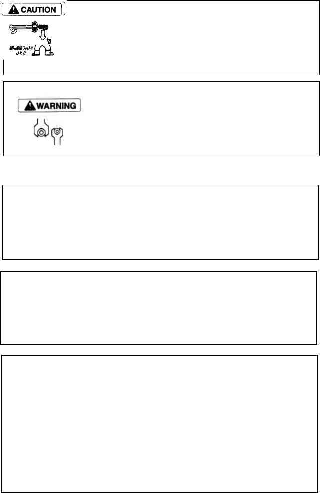
! Use of appropriate tools
Use tools appropriate for the jobs to be done. Use a correctly sized tool for loosening or tightening a machine part.
Failure to observe
A serious injury or engine damage may occur.
! Always use genuine parts
Jobs such as engine running part welding and polishing the paint with sandpaper should be done in a well-ventilated place
Failure to Observe
Shortening of MP pump unit life or an unexpected accident may arise.
! Always tighten to the specified torque if designated in the manual.
Failure to Observe
Loosening or falling may cause parts damage or injury.
Observe the following instructions with regard to waste disposal.
Negligence of each instruction will cause environmental pollution.
!Waste fluids such as engine oil and cooling water shall be discharged into a container without spillage onto the ground
!Do not let waste fluids be discharged into the sewerage a river or the sea.
!Harmful wastes such as oil, fuel, solvents, filter elements and battery shall be treated according to the respective laws and regulations. Ask a qualified collecting company for example.
3
2. General information
2.1. Outline of MP pump
MP pump is a fuel injection pump that has been newly developed to be installed on Yanmar direct injection system diesel engines for the purpose of complying with the regulation for the exhaust gas emission that are becoming tighter in the future.
The fuel injection pump is a fuel distribution type pump that supplies fuel to each cylinder of the engine through a distribution shaft by using a single plunger unlike conventional rail system or distribution system pumps.
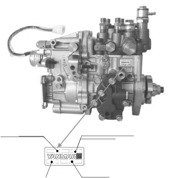
! Pump name plate
|
|
|
Fuel InjectionFIEPumpASYAsycode. code |
|
ID code for Exh.gas regulation |
|
|
Injection Pump No. |
|
|
|
ID code for production |
Serial numbers |
4
2.2. Specifications
Model |
YPD-3MP2 |
|
YPD-4MP2 |
|
YPD-4MP4 |
|
|
|
|
|
|
Applicable Engine |
3TNV82A /84(T)/88 |
|
4TNV84(T) /88 |
|
4TNV94 |
|
|
/98(T)/106(T) |
|||
|
|
|
|
|
|
Plunger Diameter (mm) |
9mm |
|
|
10mm |
|
|
|
|
|
|
|
Max. Cam Lift (mm) |
8.1mm |
|
|
10mm |
|
|
|
|
|
||
Governor-System |
Mechanical All Speed Governor |
|
|||
|
|
|
|
|
|
Fuel Injection Timing Control |
Built-in Hydraulic Control Timer |
|
|||
System |
|
||||
|
|
|
|
|
|
|
|
||||
Fuel feed pump |
Forced Lubrication System With Trochoid Pump |
||||
|
|
|
|
||
Lubrication system |
|
Engine System Oil |
|
||
|
|
|
|
|
|
Dry Weight (kg) |
8.4 |
|
8.6 |
|
11.5 |
|
|
|
|
|
|
5
2.3. Outline of fuel injection pump
Yanmar distribution type fuel injection pump YPD-MP consists of a hydraulic head that is equipped with a single plunger, a single distribution shaft, and delivery valves for each individual cylinders, a pump housing that includes camshafts, and a governor, all of which are integrated into the main unit of the pump.
For the feed of the fuel, the plunger moves up / down and the distribution shaft rotates with the revolution of the camshaft to distribute the fuel among the cylinders individually.
Specifically, one revolution of camshaft completes three cycles (for three cylinder engine) of a process, including switching over to the high pressure flow path to each cylinder with the distribution shaft, opening delivery valve, high pressure pipe, fuel injection valve, and engine cylinders in this order. This process is repeated by the revolution of the camshaft.
< The Flow of the Fuel >
12/48
orifice
|
Fuel injection pipe |
Injection pump |
|
|
||||
|
|
|
||||||
Fuel filter |
|
Timer piston |
|
Thermo-element |
||||
|
Plunger |
|
|
|
|
|
||
|
|
Distributor |
|
|
|
|
|
Engine coolant |
|
Nozzle |
shaft |
|
|
|
|
|
Accumulator |
|
|
|
|
|
|
|||
|
|
|
|
|
|
|
||
Electric fuel |
|
|
|
|
|
|
|
|
|
|
|
|
|
|
|
|
|
|
|
|
|
|
|
|
|
|
feed pump |
|
|
|
|
|
|
|
|
Water separator |
joint |
|
|
|
|
|
|
Overflow |
|
|
|
|
|
|
|
|
|
|
|
Fuel return |
tappet |
|
orifice |
|||
|
|
|
|
|
||||
Fuel tank |
|
|
|
|
|
|
|
High pressure gallery |
|
|
|
|
|
|
|
|
|
|
|
Cam |
|
|
Engine crankcase |
|||
|
Oil seal |
Engine oil |
|
|
|
|
|
|
|
Torochoid pump |
Low pressure gallery |
||||||
|
|
|||||||
Pressure control valve 
6

2.4. Construction of MP-Pump
2.4.1. Fuel Injection Part
Plug (barrel)
Holder (delivery) |
Plug (distribution shaft) |
|
|
Delivery valve CMP. |
|
Sleeve (distribution shaft) |
|
Distribution shaft |
|
Joint (distribution shaft) |
|
Removal stop |
|
(Transmission shaft) |
|
Transmission shaft |
|
Drive gear A Drive gear B
Spring (accumulator) |
Accumulator |
|
|
Plug(accumurator) |
|
Strainer (A)
Plug (C.W.)
Joint (C.W.)
Thermo element.
Holder (timer)
Piston (timer)
Hydrauric head
Packing (timer)
Barrel (plunger)
Plunger
Sleeve (control)
Spring (plunger)
Tappet (roller)
Retainer (spring)
Roller
Camshaft
Flange
Joint (FO inlet) |
Joint (overflow) |
Strainer (B)
F. O. feed pump CMP |
Control rack |
Whirl-stop (tappet) |
7
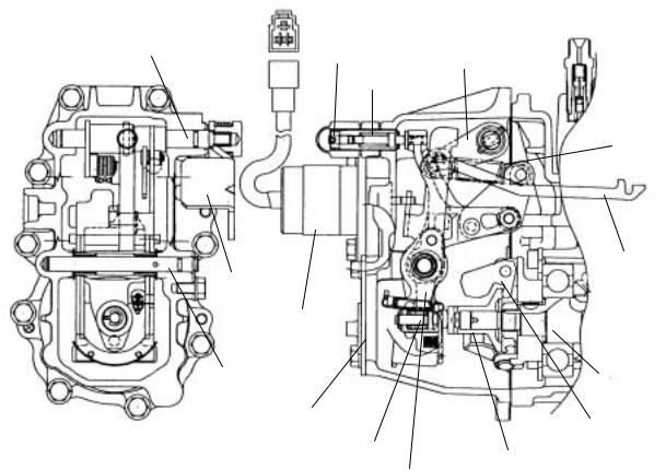
2.4.2. Governor Part
2.4.2.1. Construction of Governor
Usage condition of diesel engines are extremely varied with a wide range of loads and speeds The governor plays an important role in the operation of the engine by quickly adjusting the position of the control rack to control the amount of fuel injected, according to changes of engine speed.
It also automatically controls the engine to prevent engine speed from exceeding the maximum ,and keeps the engine from stopping.
! Mechanical governor
Shaft (Control lever) |
|
Fuel limiter CMP. |
Control lever |
|
|
Torque spring |
|
Spring (governor)
Link
Regulator lever
Stop solenoid |
|
Shaft (Governor lever) |
Camshaft |
|
|
Governor case cover |
|
|
Governor weight |
Angleich spring assembly |
Sleeve (governor) |
|
Governor lever CMP |
The governor weight mounted on the end of the fuel injection pump cam shaft rotates around the governor support pin, driven by the cam shaft, and is forced outwards by the centrifugal force acting on the weight
The thrust force acting on the cam shaft due to this centrifugal force acts on the lower part of the tension lever through the sleeve A starting excess fuel spring is mounted on the bottom of the tension lever
0ne end of the governor spring is hooked to the right upper end of the tension lever, and the other end to the spring lever of the control lever shaft.
8
As the spring lever and control lever are mounted on the same shaft, when the control lever is turned towards full, the governor spring is pulled and the load gradually increases.
Since the tension lever can move freely around the governor shaft on the player bearing, as speed increases and the shifter is pushed to the left the tension lever rotates clockwise, and when speed decreases the tension lever rotates counterclockwise.
The governor lever rotates smoothly on the second shaft installed on the tension leveb. The bottom part of this lever is in contact with the sleeve through the shifter, which is in contact with the bottom of the tension lever through the excess fuel spring. It therefore moves with the tension lever according to increases decreases in engine speed.
The top of the governor lever is connected to the fuel pump control rack through the governor link. The movement of the lever controls the volume of fuel injected by the pump. When speed increases the lever rotates clockwise to cause the control rack to reduce fuel and when speed decreases the lever rotates counterclockwise to cause the control rack to increase fuel, thus engine speed is controlled.
The top of the tension lever comes in contact with the stopper built into the top of the governor case to limit the maximum fuel injection volume.
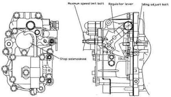
(1) Shape of control and stop levers
The control and stop levers that operate the governor |
have different shapes depending on engine design and |
method of attachment, as seen in the pictures below. |
|
The motion of the control lever is regulated by the maximum speed adjustment bolt and the idling adjustment bolt. This maintains the necessary engine speed.
9
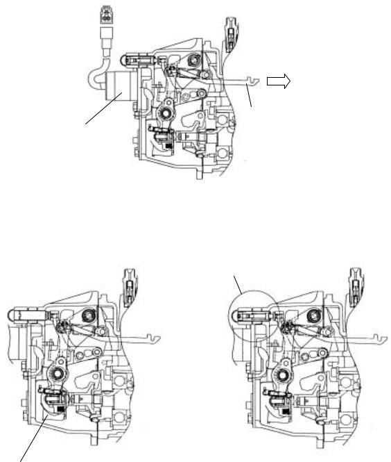
(2) Engine stop device
The magnetic solenoid is equipped to stop the engine.
Injection volume
Decrease
Link
Stop solenoid
(3)Torque rise equipment
As mentioned before this governor has a structure that allows you to equip it with an anglich and/or torque spring as torque rise equipment. In this way the requirements for different engines can full filled.
Torque spring CMP
Angleich spring CMP
10
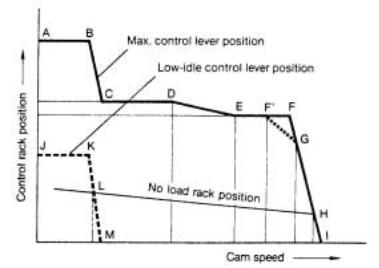
2.4.2.2. Function of Governor
(1) Function of governor
Following is a representation of the movement characteristics of the control rack at respective speeds when the speed rise from 0,with the governor control lever at the maximum speed position:
A-B : Fuel volume condition during starting. Volume is controlled by excess fuel spring.
B-C : The rack moves towards decrease after engine starts and speed increase as the load of the excess fuel spring is overcome by the centrifugal force of the governor weight.
C-D : High torque at low speed is developed by increasing fuel injection volume equivalent to the angleich stroke.
D-E : Condition when the thrust force exceeds that of the angleich spring force on the bottom of the tension lever and it gradually pushes the rack to decrease fuel when engine speed increases.
E-F : Condition when both right and left ends of the shifter come in contact with the sleeve and the bottom of the tension lever, and the control rack is kept at the normal position by the stopper. max injection volume position on models not equipped with an angleich spring)
F : Point when governor starts to take effect. This is the rated output of the engine
F’ : Point when governor start to take effect on models with torque spring G : Continuous rating point usually 85 90 injection volume of F point). H : No load max speed
L : Low-idle position
11
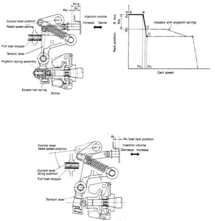
(2) Starting control
Moving the control lever to the max speed position pulls the governor spring, and moves the tension lever until it comes in contact with the control stopper.
When this is done the excess fuel spring provided in between the tension lever and governor lever holds the control rack at the maximum starting injection volume position RA-B.
After the engine is started, the excess fuel spring is compressed when the centrifugal force of the governor weight overcomes the set of the excess fuel spring as speed exceeds Nb, speed goes from B to C' (on models with angleich spring ) or B to C(on models without angleich spring ). The rack reaches the position of Rc where the governor lever and tension lever are interlocked.
3 Idling
When the control lever is returned to the idling position after the engine is started. the governor spring tension decreases and the tension lever descends clockwise, and the governor weight load keeps the governor spring and the excess fuel spring load in equilibrium to maintain idling speed at (RL).
12
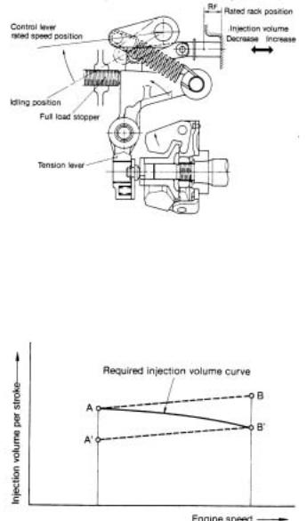
(4) Max speed
The angle of the control lever is set at determined engine speed. The governor keeps engine speed constant by adjusting sped when load changes.
For example, if the operator moves the control lever with the link from the idling position to max. Output, governor spring tension increases, the tension lever is pulled until it comes in contact with the full load stopper, the movement of the governor lever is transmitted
to the control rack via the link, maintaining the full load rack position, and engine sped increase until the governor weight thrust load and governor spring tension come into equilibrium at full load max. Speed.
(5) Necessity and function of angleich
The governor must satisfy the required injection curves represented in the diagram below in order to obtain sufficient output at low speed, and not emit black smoke at high speed. the angleich spring was devised to provide for maximum torque at low sped by setting injection volume at point A, and shifting injection volume to point B' at high engine speed.
13
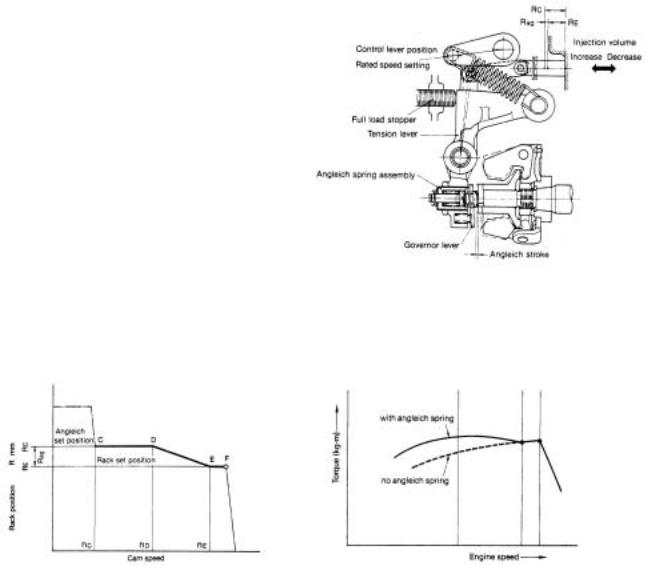
The angleich spring is mounted to the part of the tension lever (however some engine are not equipped with an angleich spring depending on usage and speed range utilized).
When engine speed is low, the governor weight cannot compress the angleich spring as the angleich spring load is lager than the governor weight, thrust load, and the control rack is held at a position (Rc) to increase injection volume.
Furthermore, as engine speed rise, the angleich spring is gradually compressed as governor weight thrust load increases and exceeds angleich load, before high speed control is effected. When the governor lever and the bottom of the tension lever come into contact (end of angleich stroke), injection volume is reduced by that amount, and the rack reaches the rated position (RE).
14
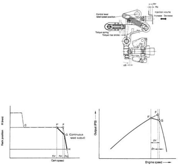
(6) Necessity of torque spring and function
Engines used in construction machinery are subjected to sudden loads which cause a decrease in speed and sometimes results in stopping of the engine. A torque spring is provided to move the control rack towards injection volume increase when engine speed decrease to increase torque to withstand overloads, and in turn prevent the engine from stopping.
The governor control lever is fixed at point G in the diagram below, the continuous rated output position.
At this time when engine is loaded, the tension lever encompasses the torque spring, the control rack comes away from full load stopper, and fluctuates between G and H according to engine load.
When the load on the engine exceeds the continuous rated output, speed decrease, governor spring tension exceeds the governor weight thrust load and overcomes the torque spring set load. The tension lever then gradually causes the control rack to move towards injection volume increase via the governor lever and link, and the torque rise stroke ends when the control rack reaches F'.
The torque spring thus provides for increasing of injection volume when speed decrease, to increase engine torque and in turn prevent engine stopping due to sudden increases in load, and also provide for strong engine output characteristics.
15
 Loading...