

Page 1

MARINE
ENGINE
6LY3
series
OPERATION MANUAL
6LY3–STC
6LY3–UTC
P/N: 0ALY3–G00200
Page 2

Disclaimers:
All information, illustrations and specifications in this manual are based on the latest
information available at the time of publishing. The illustrations used in this manual are
intended as representative reference views only. Moreover, because of our continuous
product improvement policy, we may modify information, illustrations and / or specifications
to explain and / or exemplify a product, service or maintenance improvement. We reserve
the right to make any change at any time without notice. Yanmar and are
registered trademarks of Yanmar Co., Ltd. in Japan, the United States and / or other
countries.
All Rights Reserved:
No part of this publication may be reproduced or used in any form by any means - graphic,
electronic, or mechanical, including photocopying, recording, taping, or information storage
and retrieval systems - without the written permission of Yanmar Marine International.
© 2008 Yanmar Marine International
0808
ii
6LY3 LDC Operation Manual
© 2008 Yanmar Marine International
Page 3

TABLE OF
CONTENTS
Page
Introduction......................................................................1
Record of Ownership......................................................2
Safety...............................................................................3
Safety Precautions.........................................................4
General Information ................................................. 4
Before You Operate .................................................4
During Operation and Maintenance .............................4
Location of Labels..........................................................8
Product Overview..............................................................9
Yanmar 6LY3 Features and Applications.............................9
New Engine Break-In................................................9
Component Identification...............................................11
Service Side......................................................... 11
Non-Service Side .................................................. 12
Nameplate..................................................................13
Function of Major Components........................................14
Electronic Control System (ECS).....................................15
Display................................................................ 16
DC-DC Converter.........................................................21
Items .................................................................. 21
Outline Drawing .................................................... 22
Fuse Replacement Procedure and Checking the Normal
Operation ............................................................ 22
Before You Operate..........................................................23
Diesel Fuel..................................................................23
Diesel Fuel Specifications ....................................... 23
Filling the Fuel Tank ............................................... 26
Bleeding the Fuel System........................................ 26
Engine Oil...................................................................27
Engine Oil Specifications......................................... 27
Engine Oil Viscosity ............................................... 28
6LY3 LDC Operation Manual
iii
© 2008 Yanmar Marine International
Page 4

Checking Engine Oil............................................... 28
Adding Engine Oil.................................................. 28
Selection of Marine Gear Oil .................................... 28
Engine Coolant............................................................29
Filling Heat Exchanger with Engine Coolant................. 30
Engine Operation.............................................................33
Starting the Engine.......................................................35
Before Starting the Engine....................................... 35
To Start the Engine ................................................ 35
If the Engine Fails to Start........................................ 36
After the Engine has Started .................................... 36
Shifting................................................................ 37
Neutral ................................................................ 37
Ahead................................................................. 37
Astern ................................................................. 37
Cautions During Operation.............................................38
Shutting Down the Engine..............................................40
Normal Shutdown.................................................. 40
Checking the Engine After Operation................................41
Periodic Maintenance.......................................................43
Safety Precautions.......................................................43
Precautions.................................................................45
The Importance of Periodic Maintenance .................... 45
Performing Periodic Maintenance ............................. 45
The Importance of Daily Checks ............................... 45
Keep a Log of Engine Hours and Daily Checks............. 45
Yanmar Replacement Parts ..................................... 45
Tools Required ..................................................... 45
Ask Your Authorized Yanmar Marine Dealer for Help ..... 45
Required EPA Maintenance - USA Only ..................... 45
EPA Installation Requirements - USA Only .................. 46
Tightening Fasteners.............................................. 46
Periodic Maintenance Schedule......................................47
Inspection and Maintenance of EPA Emission-Related
Parts................................................................... 49
Periodic Maintenance Procedures....................................50
Daily Checks ........................................................ 50
After Initial 50 Hours of Operation.............................. 51
Every 50 Hours of Operation .................................... 53
Every 250 Hours of Operation .................................. 57
Every 500 Hours of Operation .................................. 60
Every 1000 Hours of Operation................................. 60
Every 2000 Hours of Operation................................. 61
EPA Requirements.......................................................62
EPA Certification Plates .......................................... 62
TABLE OF CONTENTS
iv
6LY3 LDC Operation Manual
© 2008 Yanmar Marine International
Page 5

Conditions to Ensure Compliance with EPA Emission
Standards............................................................ 63
Inspection and Maintenance .................................... 63
Troubleshooting..............................................................65
Troubleshooting After Starting.........................................65
Troubleshooting Information........................................... 66
Troubleshooting Chart...................................................67
Long-Term Storage..........................................................69
Before You Place the Engine in Long-Term Storage.............69
Returning the Engine to Service.......................................70
Specifications..................................................................71
Principal Engine Specifications........................................71
Wiring Diagrams.................................................... 73
EPA Warranty USA Only....................................................77
Yanmar Co., Ltd. Limited Emission Control System Warranty
- USA Only..................................................................77
Your Warranty Rights and Obligations: ....................... 78
Warranty Period: ................................................... 78
Warranty Coverage: ............................................... 79
Exclusions: .......................................................... 79
Owner’s Responsibility: .......................................... 79
Customer Assistance: ............................................ 79
Maintenance Log................................................... 80
TABLE OF CONTENTS
6LY3 LDC Operation Manual
v
© 2008 Yanmar Marine International
Page 6

This Page Intentionally Left Blank
TABLE OF CONTENTS
vi
6LY3 LDC Operation Manual
© 2008 Yanmar Marine International
Page 7

INTRODUCTION
Welcome to the world of Yanmar Marine!
Yanmar Marine offers engines, drive
systems and accessories for all types of
boats, from runabouts to sailboats, and from
cruisers to mega yachts. In marine light duty
commercial boating, the worldwide
reputation of Yanmar Marine is second to
none. We design our engines to respect
nature. This means quieter engines, with
minimal vibrations, cleaner than ever. All of
our engines designed after 1996 meet most
of the present and future emission
regulations, like BSO II, SAV, EPA II, IMO
and RCD.
To help you enjoy your Yanmar 6LY3 engine
for many years to come, please follow these
recommendations:
• Read and understand this Operation
Manual before you operate the machine to
ensure that you follow safe operating
practices and maintenance procedures.
• Keep this Operation Manual in a
convenient place for easy access.
• If this Operation Manual is lost or
damaged, order a new one from your
authorized Yanmar Marine dealer or
distributor.
• Make sure this manual is transferred to
subsequent owners. This manual should
be considered a permanent part of the
engine and remain with it.
• Constant efforts are made to improve the
quality and performance of Yanmar
products, so some details included in this
Operation Manual may differ slightly from
your engine. If you have any questions
about these differences, please contact
your authorized Yanmar Marine dealer or
distributor.
• The specifications and components
(instrument panel, fuel tank, etc.)
described in this manual may differ from
ones installed on your vessel. Please refer
to the manual provided by the
manufacturer of these components.
• Refer to the Yanmar Limited Warranty
Handbook for a complete warranty
description.
6LY3 LDC Operation Manual
1
© 2008 Yanmar Marine International
Page 8

RECORD OF OWNERSHIP
Take a few moments to record the information you need when you contact Yanmar for
service, parts or literature.
Engine Model:
Engine Serial No.:
Date Purchased:
Dealer:
Dealer Phone:
INTRODUCTION
2
6LY3 LDC Operation Manual
© 2008 Yanmar Marine International
Page 9

SAFETY
Yanmar considers safety of great
importance and recommends that anyone
that comes into close contact with its
products, such as those that install, operate,
maintain or service Yanmar products,
exercise care, common sense and comply
with the safety information in this manual
and on the machine’s safety labels. Keep
the labels from becoming dirty or torn and
replace them if they are lost or damaged.
Also, if you need to replace a part that has a
label attached to it, make sure you order the
new part and label at the same time.
!
This safety alert symbol appears
with most safety statements. It
means attention, become alert,
your safety is involved! Please
read and abide by the message
that follows the safety alert
symbol.
DANGER
Indicates an hazardous situation which, if
not avoided, will result in death or serious
injury.
WARNING
Indicates a hazardous situation which, if not
avoided, could result in death or serious
injury.
CAUTION
Indicates a hazardous situation which, if not
avoided, could result in minor or moderate
injury.
NOTICE
Indicates a situation which can cause
damage to the engine, personal property
and / or the environment or cause the
equipment to operate improperly.
6LY3 LDC Operation Manual
3
© 2008 Yanmar Marine International
Page 10

SAFETY PRECAUTIONS
General Information
There is no substitute for common sense
and careful practices. Improper practices or
carelessness can cause burns, cuts,
mutilation, asphyxiation, other bodily injury
or death. This information contains general
safety precautions and guidelines that must
be followed to reduce risk to personal safety.
Special safety precautions are listed in
specific procedures. Read and understand
all of the safety precautions before operation
or performing repairs or maintenance.
Before You Operate
DANGER
The safety messages that follow have
WARNING level hazards.
NEVER permit anyone to install or
operate the engine without proper
training.
• Read and understand this Operation
Manual before you operate or service the
engine to ensure that you follow safe
operating practices and maintenance
procedures.
• Safety signs and labels are additional
reminders for safe operating and
maintenance techniques.
• See your authorized Yanmar Marine
dealer or distributor for additional training.
During Operation and
Maintenance
DANGER
The safety message that follows has
DANGER level hazards.
Crush Hazard
NEVER stand under hoisted
engine. If the hoist
mechanism fails, the engine
will fall on you.
SAFETY
4
6LY3 LDC Operation Manual
© 2008 Yanmar Marine International
Page 11

WARNING
The safety messages that follow have
WARNING level hazards.
Explosion Hazard
While the engine is running or
the battery is charging,
hydrogen gas is being
produced and can be easily
ignited. Keep the area around
the battery well-ventilated and keep sparks,
open flames and any other form of ignition
out of the area.
Fire and Explosion Hazard
Diesel fuel is flammable and explosive
under certain conditions.
NEVER use a shop rag to catch the fuel.
Wipe up all spills immediately.
NEVER refuel with the engine running.
NEVER use diesel fuel as a cleaning agent.
Store any containers containing fuel in a
well-ventilated area, away from any
combustibles or sources of ignition.
Fire Hazard
Undersized wiring systems
can cause an electrical fire.
Store any equipment in a designated area
away from moving parts.
NEVER use the engine compartment for
storage.
Sever Hazard
Rotating parts can cause
severe injury or death.
NEVER wear jewelry,
unbuttoned cuffs, ties or loose
fitting clothing and ALWAYS
tie long hair back when working near
moving / rotating parts such as the flywheel
or PTO shaft. Keep hands, feet and tools
away from all moving parts.
Alcohol and Drug Hazard
NEVER operate the engine
while under the influence of
alcohol or drugs or feeling ill.
Exposure Hazard
ALWAYS wear personal
protective equipment
including appropriate
clothing, gloves, work shoes,
eye and hearing protection as
required by the task at hand.
Entanglement Hazard
NEVER leave the key in the
key switch when you are
servicing the engine.
Someone may accidentally
start the engine and not
realize you are servicing it.
NEVER operate the engine while wearing a
headset to listen to music or radio because
it will be difficult to hear the warning signals.
SAFETY
6LY3 LDC Operation Manual
5
© 2008 Yanmar Marine International
Page 12
WARNING
Piercing Hazard
Avoid skin contact with highpressure diesel fuel spray
caused by a fuel system leak
such as a broken fuel injection
line. High-pressure fuel can
penetrate your skin and result in serious
injury. If you are exposed to high-pressure
fuel spray, obtain prompt medical treatment.
NEVER check for a fuel leak with your
hands. ALWAYS use a piece of wood or
cardboard. Have your authorized Yanmar
Marine dealer or distributor repair the
damage.
Burn Hazard
Some of the engine surfaces
become very hot during
operation and shortly after
shutdown. Keep hands and
other body parts away from
hot engine surfaces.
Sudden Movement Hazard
ALWAYS stop the engine before beginning
service.
Exhaust Hazard
NEVER block windows, vents
or other means of ventilation if
the engine is operating in an
enclosed area. All internal
combustion engines create
carbon monoxide gas during operation and
special precautions are required to avoid
carbon monoxide poisoning.
CAUTION
The safety messages that follow have
CAUTION level hazards.
Poor Lighting Hazard
Ensure that the work area is adequately
illuminated. ALWAYS install wire cages on
portable safety lamps.
Tool Hazard
ALWAYS use tools appropriate for the task
at hand and use the correct size tool for
loosening or tightening machine parts.
Flying Object Hazard
ALWAYS wear eye protection when
servicing the engine or when using
compressed air or high-pressure water.
Dust, flying debris, compressed air,
pressurized water or steam may injure your
eyes.
Coolant Hazard
Wear eye protection and
rubber gloves when you
handle Long Life engine
coolant. If contact with the
eyes or skin should occur,
flush eyes and wash immediately with clean
water.
SAFETY
6
6LY3 LDC Operation Manual
© 2008 Yanmar Marine International
Page 13

NOTICE
The safety messages that follow have
NOTICE level hazards.
It is important to perform daily checks as
listed in the Operation Manual. Periodic
maintenance prevents unexpected
downtime, reduces the number of accidents
due to poor engine performance and helps
extend the life of the engine.
See your authorized Yanmar Marine dealer
or distributor if you need to operate the
engine at high altitudes. At high altitudes the
engine will lose power, run rough and
produce exhaust gases that exceed the
design specifications.
ALWAYS be environmentally
responsible.
Follow the guidelines of the
EPA or other governmental
agencies for the proper
disposal of hazardous materials such as
engine oil, diesel fuel and engine coolant.
Consult the local authorities or reclamation
facility.
NEVER dispose of hazardous materials by
dumping them into a sewer, on the ground
or into ground water or waterways.
If a Yanmar Marine engine is installed at an
angle that exceeds the specifications stated
in the Yanmar Marine installation manuals,
engine oil may enter the combustion
chamber, causing excessive engine speed,
white exhaust smoke and serious engine
damage. This applies to engines that run
continuously or those that run for short
periods of time.
If you have an installation with two or three
engines and only one engine is operating,
the water pickup (thru-hull) of the nonrunning engine(s) should be closed. This will
prevent water from being forced past the
seawater pump and eventually finding its
way into the engine. The result of water
entering the engine could cause seizure or
other serious problems.
If you have an installation with two or three
engines, and only one engine is operating,
please note that if the propeller shaft thruhull (stuffing box) is lubricated by engine
water pressure and the engines are
interconnected, care must be taken that
water from the running engine does not
enter the exhaust of the non-running
engine(s). This water could cause seizure of
the non-running engine(s). See your
authorized Yanmar Marine dealer or
distributor for a complete explanation of this
condition.
If you have an installation with two or three
engines, and only one engine is operating,
it is important to limit the amount of throttle
applied to the running engine. If you observe
black smoke or movement of the throttle
does not increase engine rpm, you are
overloading the engine that is running.
Immediately throttle back to approximately
2/3 throttle or to a setting where the engine
performs normally. Failure to do so may
cause the running engine to overheat or
cause excess carbon buildup which may
shorten the engine’s life.
SAFETY
6LY3 LDC Operation Manual
7
© 2008 Yanmar Marine International
Page 14

LOCATION OF LABELS
Figure 1 shows the location of regulatory
and safety labels on Yanmar 6LY3 series
engines. Please replace if damaged or lost.
0002079
(5)
(1)
(2)
(1)
(4)
(3)
Figure 1
1 – Part Number: 128296-07300
2 – Part Number: 120324-07240
3 – Part Number: 128296-07260
4 – Part Number: 128296-07350
5 – Part Number: 119578-07890
128296-07300
120324-07240
128296-07260
128296-07350
119578-07890
DO NOT STEP
ON COVERS.
POSSIBILITY
OF A FALL
SAFETY
8
6LY3 LDC Operation Manual
© 2008 Yanmar Marine International
Page 15

PRODUCT OVERVIEW
YANMAR 6LY3 FEATURES
AND APPLICATIONS
The engine is equipped with a marine gear.
The marine gear output shaft connects with
the propeller shaft. In order to obtain full
performance from your engine, it is
imperative that you check the size and
structure of the hull and use a propeller of
the appropriate size. As new boats are used,
owners add additional equipment and
completely fill the fuel and water tanks,
adding to the overall displacement (weight)
of the vessel. Extra canvas enclosures,
bottom paint and bottom fouling can add
additional hull resistance. It is
recommended that a new vessel be
propped so the engine operates at 95% load
at 3300 rpm. Failure to do so can lead to
reduced vessel performance, lead to
increased smoke levels and cause
permanent damage to your engine.
The engine must be installed correctly with
the seawater or cooling water piping,
exhaust gas piping and electrical wiring. Any
auxiliary equipment attached to the engine
should be easy to use and accessible for
service. To handle the drive equipment,
propulsion systems (including the propeller)
and other onboard equipment, be sure to
observe the instructions and cautions given
in the operation manuals supplied by the
shipyard and equipment manufacturers.
The laws of some countries may require hull
and engine inspections, depending on the
use, size and cruising area of the boat. The
installation, fitting and surveying of this
engine all require specialized knowledge
and engineering skills. See Yanmar’s local
subsidiary in your region or your authorized
Yanmar Marine dealer or distributor.
This engine is designed for light duty
commercial applications. The engine is
designed to be operated at maximum
throttle (3300 rpm) for less than 5% of its
total operation time (30 minutes out of every
10 hours). The engine should be operated
at cruising speed (3200 rpm) for less than
90% of its total operation time (9 hours out
of every 10 hours).
New Engine Break-In
As with all reciprocating engines, the way
your engine is operated during its first 50
hours of operation plays a very significant
role in determining how long it will last and
how well the engine will perform over its
lifetime.
A new Yanmar diesel engine must be
operated at suitable speeds and power
settings during the break-in period to make
the sliding parts, such as piston rings, break
in properly and to stabilize engine
combustion.
During the break-in period, the engine
coolant temperature gauge should be
monitored; temperature should be between
71 and 87C (160 and 190F).
6LY3 LDC Operation Manual
9
© 2008 Yanmar Marine International
Page 16

During the first 10 hours of operation, the
engine should be run at maximum rpm
minus 400 - 500 rpm (approximately
60 - 70% of load) most of the time. This will
ensure the sliding parts break in properly.
During this period, avoid operating at
maximum engine speed and load to avoid
damaging or scoring sliding parts.
NOTICE: Do not operate at WOT (wide open
throttle) for more than a minute at a time
during the first 10 hours of operation.
Do not operate the engine at low idle or at
low speed and light load for more than
30 minutes at a time. Since unburned fuel
and engine oil will adhere to the piston rings
when operating at low speeds for long
periods, this will interfere with proper
movement of the rings and the lube oil
consumption may increase. Low idle speed
does not allow break-in of sliding parts.
If operating engine at low speed and light
load, you must race the engine to clean the
carbon from the cylinders and fuel injection
valve.
Perform this procedure in open waters:
• With the clutch in NEUTRAL, accelerate
from the low speed position to the high
speed position briefly.
• Repeat this process five times.
Once past the initial 10 hours until 50 hours,
the engine should be used over its full
operating range, with special emphasis on
running at relatively high power settings.
This is not the time for an extended cruise at
idle or low speed. The boat should be run at
maximum speed minus 400 rpm most of the
time (approximately 70% load), with a 10
minute run at maximum minus 200 - 300 rpm
(approximately 80% load) every 30 minutes
and a 4 - 5 minute period of operation at
WOT (wide open throttle) once each 30
minutes. During this period, be sure not to
operate your engine at low speed and light
load for more than 30 minutes. If operating
engine at low speed and light load by
necessity, just after the low idle operation,
be sure to race the engine.
To complete engine break-in, perform After
Initial 50 Hours maintenance procedures.
See Periodic Maintenance Schedule on
page 47.
PRODUCT OVERVIEW
10
6LY3 LDC Operation Manual
© 2008 Yanmar Marine International
Page 17

COMPONENT IDENTIFICATION
Service Side
(1)
(3)
(4)
(5)
(6)
(7)
(8)
(9)
(10)
0002020
(2)
Figure 1
1 – Oil Fill Cap
2 – Coolant Fill Cap
3 – Electronic Control Unit Cover
Plate
4 – Fuel Injection Pump
5 – Lube Oil Cooler
6 – Lube Oil Filter
7 – Inter-Cooler
8 – Flywheel
9 – Air Intake Silencer
10–Turbocharger
PRODUCT OVERVIEW
6LY3 LDC Operation Manual
11
© 2008 Yanmar Marine International
Page 18

Non-Service Side
0002021
(4)
(1)
(3)
(5)
(2)
(6)
(7)
(8)
Figure 2
1 – Coolant Tank (Exhaust Manifold)
2 – Dipstick
3 – Freshwater Cooler
4 – Seawater Pump
5 – Alternator
6 – V-Belt
7 – Fuel Filter
8 – Freshwater Pump
PRODUCT OVERVIEW
12
6LY3 LDC Operation Manual
© 2008 Yanmar Marine International
Page 19

NAMEPLATE
The engine nameplate and its typical
location is shown in Figure 3. Replace if
damaged or lost. Check the engine model,
output, rpm and serial number on the
nameplate.
0006472
/
Gear Model
ENG.No.
/
Model
min
-1
min
-1
min
-1
Continuous power kW
Speed of prop,shaf t
Fuel stop power kW
Figure 3
PRODUCT OVERVIEW
6LY3 LDC Operation Manual
13
© 2008 Yanmar Marine International
Page 20

FUNCTION OF MAJOR COMPONENTS
Name of Component Function
Fuel Filter
Removes dirt and water from the fuel. Drain the filter periodically. The filter element
should be replaced periodically. See Replace the Fuel Filter Element on page
51.
Fuel Feed Pump
Pumps fuel from tank to the fuel injection pump. Equipped with built-in centrifugal
vane.
Engine Oil Fill Port The fill port used to add engine lubricating oil.
Lubricating Oil Filter (at
full-flow and bypass
sides)
Filters fine metal fragments and carbon from the lubricating oil. Filtered lube oil is
distributed to the engine’s moving parts.
Cooling Water System
There are two cooling systems: freshwater and seawater. The engine’s combustion heat is cooled by the fresh water / coolant in a closed circuit. The fresh water
is cooled by seawater using heat exchanger. The seawater also cools the lube oil
of engine / marine gear and also intake air through coolers in an open circuit.
Freshwater Cooler
The freshwater cooler is a heat exchanger to cool the fresh water by using seawater.
Freshwater Pump
The centrifugal water pump circulates fresh cooling water inside the engine. The
fresh water pump is driven by V-belt.
Seawater Pump
The rubber impeller type pump raises seawater for cooling. Never operate it without seawater, as this will damage the impeller.
Freshwater / Coolant Fill
Cap
The fill cap on the coolant tank covers the water supply port. The cap has a pressure regulating valve. When the cooling water temperature rises, the pressure
rises inside the freshwater system.
Coolant Recovery Tank
The pressure regulating valve releases vapor and hot water overflow to the coolant
recovery tank. When the engine stops and the cooling water cools, the pressure
in the cooling water tank also drops very low. The fill cap valve then opens to send
water back from the coolant recovery tank. This minimizes cooling water consumption. Freshwater / coolant level can easily be checked and refilled in this tank.
Oil Cooler
This heat exchanger cools high temperature lube oil with seawater.
Turbocharger
The pressurized intake air feeding device: the exhaust gas turbine is rotated by
the exhaust gas, and the power is used to rotate the blower. This pressurizes the
intake air for sending to the cylinder.
Inter-Cooler
This heat exchanger cools the pressurized intake air from the turbocharger with
seawater.
Anti-Corrosion Zinc
Anode
The metal area of the seawater cooling system is prone to electrical corrosion. The
anti-corrosion zinc anode is installed in the oil cooler, aftercooler, etc. to prevent
this. The anti-corrosion zinc anode is itself reduced over time by electrical corrosion, so it must be replaced at fixed intervals before it is completely consumed in
order to ensure that the metal area of the seawater cooling system remains fully
protected.
Nameplates
Nameplates are provided on the engine and the marine gear and include the model, serial number and other data.
Starter Starter motor for the engine. Powered by the battery.
Alternator Driven by V-belt and generates electricity and charges the battery.
PRODUCT OVERVIEW
14
6LY3 LDC Operation Manual
© 2008 Yanmar Marine International
Page 21

ELECTRONIC CONTROL
SYSTEM (ECS)
the control equipment consists of the rocker
switch panel, the display, engine interface
module and the control head, which are
connected by the wire harness to the engine
(electronic governor and marine gear) for
remote control operation.
See Yanmar Electronic Control System
Operation Manual for LY3 Engines for a
more complete description of the electronic
control system (ECS).
Start
Eng ON
OFF
Emergency
Stop
Sub throttle active
Sub throttle
Model:i2 Module
0002022
(3)
(4)
(1)
(2)
(8)
(5)
(7)
(6)
(9)
Figure 4
1 – First Station Rocker Switch
Panel
2 – To Engine
3 – Interface Module Without
Trolling Interface Module with
Trolling (optional)
4 – To Engine
5 – To Marine Gear
6 – NMEA Tee and Terminators Kit
7 – NMEA Tee Connector
8 – Digital Display
9 – Control Head (shift and throttle)
PRODUCT OVERVIEW
6LY3 LDC Operation Manual
15
© 2008 Yanmar Marine International
Page 22
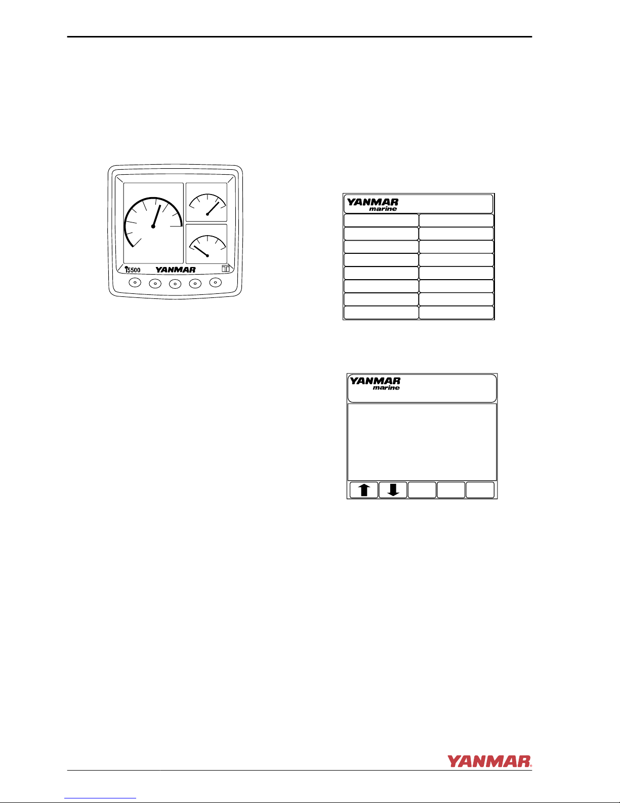
Display
Refer to the Electronic Control System
Manual for 6LY3, available as a separate
volume, for details.
Display Function
Runtime Engine Data Tri-Screen
(Figure 5)
0
1
2
3
4
WTR TEMP
X1000
RPM
PSi
84
2615
0 100
100 250
114 Fah
SINGLE
OIL PRES
0002023
Figure 5
This screen displays real time engine data
and alarm indications.
Alarm Indicators (Figure 6)
Alarm window appears with an audible
alarm when abnormal engine activity
occurs.
Note: When starting the engine, make it a
rule to check for any highlighted alarms. If
the system does not function normally,
contact your authorized Yanmar Marine
dealer and ask for diagnostics.
DUAL PORT
Alarms
HOT ENGINE
OVER REV
OIL PRESSURE
TURBO BOOST
GEAR OIL
ENG COM ERROR
MAINTENANCE
NETWORK
CHECK ENGINE
EMERGENCY
LOW VOLTAGE
ALTERNATOR
SEA WATER FLOW
LOW COOLANT
WATER IN FUEL
THROTTLE PROBLEM
0002024
Figure 6
Alarm Log Screen (Figure 7)
Alarm Log
061803
CONTACT YANMAR DISTRIBUTOR
17:04- COM ERROR Y 025
P0120/FEB0 THROTTLE SENSOR
VALUE OUT OF RANGE.
CLR
Port Eng Alarms
EXIT
0002025
Figure 7
PRODUCT OVERVIEW
16
6LY3 LDC Operation Manual
© 2008 Yanmar Marine International
Page 23

Alarm Indicator Functions
Alarm indicators and buzzer come on when
sensors detect an abnormality during
engine operation. The alarm indicators are
off during normal operation, but come on as
follows when an abnormality arises:
• Cooling water temperature alarm indicator
comes on when the fresh water gets too
hot.
• Lube oil pressure alarm indicator comes
on when the engine lube oil pressure
drops.
• Electric charge alarm indicator comes on
when there is a charging failure.
Rocker Switch Panel
The rocker switch panel has the following
functions.
1st Station Panel (Figure 8)
Start
Eng ON
OFF
Emergency
Stop
Sub throttle active
Sub throttle
0002026
1
3
2
Figure 8
1. To start and stop the engine:
• To start the engine, push upper half of
Eng ON switch (Start).
• To stop the engine, push bottom half of
Eng ON switch (OFF).
Note: The engine will take 2 to 7 seconds to
stop running after the bottom of the rocker
switch is pressed.
2. Emergency Stop (Figure 8, (2))
NOTICE: Use this switch only in an
emergency. Under normal
circumstances, use the Eng ON switch
(Figure 8, (1)) to stop the engine.The
engine shuts down suddenly when the
upper half of the Emergency Stop switch
is pushed. Push the bottom half of the
switch after the engine has shut down to
return the switch to the center.
Note: Restarting the engine after using the
Emergency Stop switch may be slower or
more difficult than normal starting.
3. Sub throttle Control (Figure 8, (3))
In the unlikely event that the throttle
control fails, the Sub throttle indicator
light will flash and the engine speed is
controlled by the Sub throttle. Engine
speed rises when the Sub throttle knob
is turned clockwise.
• When the Sub throttle indicator
flashes, turn the Sub throttle knob
counterclockwise to the end and turn
the knob clockwise gradually until the
Sub throttle indicator turns on (steady
light).
• Each engine is controlled by a
dedicated Sub throttle controller.
PRODUCT OVERVIEW
6LY3 LDC Operation Manual
17
© 2008 Yanmar Marine International
Page 24

2nd Station Panel - Optional (Figure 9)
Start
Eng ON
OFF
Emergency
Stop
0002027
1
2
Figure 9
1. Eng ON switch (Figure 9, (1)) is wired to
1st station panel.
2. Able to start and stop the engine from
2nd station panel
3. Emergency Stop switch is wired in series
with 1st station panel (Figure 9, (2)).
Wiring Diagrams
For Instrument Panel wiring diagrams,
please contact your authorized Yanmar
Marine dealer or distributor, or refer to the
relevant Installation Manual or Service
Manual.
Control Head Shift and Throttle
Functions
Use the two-lever control head
(Figure 10, (4)) in the helm station for
AHEAD (Figure 10, (1)), ASTERN
(Figure 10, (3)), NEUTRAL
(Figure 10, (2)) and speed control in a twin
installation.
0002028
1
3
2
4
Figure 10
Use the single-lever control head
(Figure 11, (4)) in the helm station for
AHEAD (Figure 11, (1)), ASTERN
(Figure 11, (3)), NEUTRAL
(Figure 11, (2)) and speed control in a
single installation.
0002029
4
3
2
1
Figure 11
Control Head Button Functions
• N (or NEUTRAL) Button – If the associated
control head lever is in the “Neutral Idle”
position, pushing this button engages /
disengages Neutral Throttle control,
allowing throttle but no forward or reverse
thrust. If the associated control head lever
is in a “Gear Idle” position, pushing this
button engages / disengages Split Range
Throttle (SRT) (if installed).
• SELECT (or SEL) Button – If the station is
inactive, pushing this button activates the
station (used in conjunction with two or
more control stations).
• SYNC Button – Pushing this button
engages / disengages the Cruise
Synchronization option (if installed) when
the port and starboard control head levers
are set to nearly the same positions.
PRODUCT OVERVIEW
18
6LY3 LDC Operation Manual
© 2008 Yanmar Marine International
Page 25

Control Head Operation
Selecting Active Station:
N
F
R
N
F
R
N N
SELECT
SYNC
N
F
R
N
F
R
N N
SELECT
SYNC
N
F
R
N
F
R
N N
SELECT
SYNC
0002030
1 32
Figure 12
1. (Figure 12, (1)) shows a typical inactive
station.
2. Press the SELECT button
(Figure 12, (2)). The button lights
(grayed in Figure 12) and the station
select light flashes (star around light in
(Figure 12)).
3. Move the handle(s) to F (forward) or R
(reverse) throttle to match the handle
location of the active station
(Figure 12, (3)). The corresponding
handle button lights glow steady (grayed
in (Figure 12, (3))) and the station select
light glows steady (grayed in
(Figure 12, (3))).
Engaging / Disengaging Shift Disconnect
Mode:
N
F
R
N
F
R
N N
SELECT
SYNC
N
F
R
N
F
R
N N
SELECT
SYNC
N
F
R
N
F
R
N N
SELECT
SYNC
N
F
R
N
F
R
N N
SELECT
SYNC
N
F
R
N
F
R
N N
SELECT
SYNC
0002044
1
54
32
Figure 13
Engage:
1. Return the handle(s) to N (neutral). The
neutral light(s) glow steady
(Figure 13, (1)).
2. Press the N (neutral) button(s)
(Figure 13, (2)). The neutral light(s)
flash (star around light(s) in
(Figure 13, (2)).
3. Move the handle(s) to forward or reverse
throttle (Figure 13, (3)) resulting in
engine rpm control without engaging
marine gear.
Disengage:
1. Return the handle(s) to N (neutral)
(Figure 13, (4)).
2. Press the N (neutral) button(s)
(Figure 13, (5)). The neutral light(s)
glow steady (Figure 13, (5)).
PRODUCT OVERVIEW
6LY3 LDC Operation Manual
19
© 2008 Yanmar Marine International
Page 26

Engaging / Disengaging Split Range
Throttle (SRT):
Note: Split Range Throttle is not available if
the boat is equipped with the Trolling option.
The Split Range Throttle control head mode
gives you greater throttle sensitivity. In Split
Range Throttle (SRT), moving an engine’s
control lever all the way to the “Full Forward”
position will only produce the maximum
percentage of wide open throttle selected in
the “Features Selection” of the ECU
program options. Typical Throttle Limit
percentages for SRT are 5% to 50%, with
25% being the default value.
N
F
R
N
F
R
N N
SELECT
SYNC
N
F
R
N
F
R
N N
SELECT
SYNC
N
F
R
N
F
R
N N
SELECT
SYNC
0002045
1
3
2
Figure 14
Engage:
1. Move the engine’s lever to an in-gear idle
position (Forward Idle or Reverse Idle)
(Figure 14, (1)) and press the N
(neutral) button (Figure 14, (2)) next to
this lever on the control head. The N
(neutral) lamp (Figure 14, (2)) will flash
to indicate that the Split Range Throttle
is engaged.
2. While in the Split Range Throttle, the
system will shift normally but the throttle
will be limited in both gears.
3. If the system is shifted into neutral while
in the Split Range Throttle engine mode,
the N (neutral) lamp will come on
(steady) to indicate that the system is in
neutral. When the lever is moved back
into gear, the N (neutral) lamp will
resume flashing to indicate that the
system is still in Split Range Throttle.
Disengage:
Return the engine lever to a Gear Idle
position (Forward Idle or Reverse Idle)
(Figure 14, (3)). Press the N (neutral)
button next to the lever on the control head.
The N (Neutral) lamp will stop flashing,
indicating that the Split Range Throttle has
been disengaged.
PRODUCT OVERVIEW
20
6LY3 LDC Operation Manual
© 2008 Yanmar Marine International
Page 27

Engaging / Disengaging Cruise
Synchronization:
N
F
R
N
F
R
N N
SELECT
SYNC
N
F
R
N
F
R
N N
SELECT
SYNC
N
F
R
N
F
R
N N
SELECT
SYNC
N
F
R
N
F
R
N N
SELECT
SYNC
N
F
R
N
F
R
N N
SELECT
SYNC
0 - 5%
0002041
1 3
54
2
Figure 15
Engage:
1. Disengage any other engine mode being
used.
2. Match all engine shift and throttle
settings by moving the active port and
starboard control head levers to within
5% of each other (Figure 15, (1)) and
press the SYNC button (Figure 15, (4))
on the control head. The sync lamp
flashes if the handles are not within 5%
of each other (Figure 15, (3)). The sync
lamp will stop flashing and remain
continuously lit (Figure 15, (4)) when
the levers are moved to within this 5%
range.
A steady sync lamp confirms that the
Cruise Sync is engaged. While the
engines are synchronized, all engine
speeds are matched any time the control
levers are set to within 5% of each other
and are above 20% throttle.
Disengage:
Press the SYNC button on the control head.
DC-DC CONVERTER
DC-DC converter is a type of voltage
converter, which converts direct-current
electricity to arbitrary direct current voltage.
133
52
83
96.5
(1)
(2)
(3)
(4)
024522-00X
1 – 6LY3-LDC Electric Control
System Harness Side
2 – Input Line
3 – Output Line
4 – Relay Harness
Items
Product Name Switched-mode
DC-DC converter
Model HADC-20
Input voltage DC18 - 32 V
Output voltage DC13.8V (±5%)
Output current 15A
Operating temperature -10 - 60°C
Storage temperature -40 - 85°C
PRODUCT OVERVIEW
6LY3 LDC Operation Manual
21
© 2008 Yanmar Marine International
Page 28

Outline Drawing
1500
(3)
(2)
(5) (6)
(4)
(1)
18~32V
024523-00X
HADC-20
1 – Input Electric Cable
2 – 18-32V (Blue) +
3 – Ground (Black) -
4 – Ground
5 – Fuse Holder (MF-506)
6 – LA8Ø Terminal
Fuse Replacement Procedure and Checking the Normal Operation
Check the normal operation when the instrument panel key switch is turned to the ON position
Fuse replacement procedure
Output side: 13.8V±5% Replace the 15A glass tube in the 24V+ input side.
PRODUCT OVERVIEW
22
6LY3 LDC Operation Manual
© 2008 Yanmar Marine International
Page 29

BEFORE YOU OPERATE
This section of the Operation Manual
describes the diesel fuel, engine oil, and
engine coolant specifications and how to
replenish them. It also describes the daily
engine checkout.
Before performing any operations within this
section, review the Safety section on
page 4.
DIESEL FUEL
DANGER! Diesel fuel is flammable and
explosive under certain conditions.
Refer to Fire and Explosion Hazard on
page 5.
Diesel Fuel Specifications
NOTICE: Only use diesel fuels
recommended by Yanmar Marine for the
best engine performance, to prevent engine
damage and to comply with EPA warranty
requirements. Only use clean diesel fuel.
Diesel fuel should comply with the following
specifications. The table lists several
worldwide specifications for diesel fuels.
DIESEL FUEL
SPECIFICATION
LOCATION
No. 2-D, No. 1-D, ASTM
D975
USA
EN590:96 European Union
ISO 8217 DMX International
BS 2869-A1 or A2 United Kingdom
JIS K2204 Grade No. 2 Japan
6LY3 LDC Operation Manual
23
© 2008 Yanmar Marine International
Page 30

Bio-Diesel Fuels
Yanmar approves the use of biodiesel fuels
that do not exceed a blend of 5% nonmineral oil based fuel with 95% standard
diesel fuel. Such biodiesel fuels are known
in the marketplace as B5 biodiesel fuels. B5
biodiesel fuel can reduce particulate matter
and the emission of “greenhouse” gases
compared to standard diesel fuel.
CAUTION! If the B5 biodiesel fuel used
does not meet the approved
specifications, it will cause abnormal
wear of injectors, reduce the life of the
engine and it may affect the warranty
coverage of your engine.
B5 diesel fuels must meet certain
specifications
The biodiesel fuels must meet the minimum
specifications for the country in which they
are used:
• In Europe, biodiesel fuels must comply
with the European Standard EN14214.
• In the United States, biodiesel fuels must
comply with the American Standard ASTM
D-6751.
Biodiesel should be purchased only from
recognized and authorized diesel fuel
suppliers.
Precautions and concerns regarding
the use of bio-fuels:
• Biodiesel fuels have a higher content of
methyl-esters, which may deteriorate
certain metal, rubber and plastic
components of the fuel system. The
customer and / or boat builder are
responsible to verify the usage of biodiesel
compatible components on the vessel fuel
supply and return systems.
• Free water in biodiesel may result in
plugging of fuel filters and increased
bacterial growth.
• High viscosity at low temperatures may
result in fuel delivery problems, injection
pump seizures, and poor injection nozzle
spray atomization.
• Biodiesel may have adverse effects on
some elastomers (seal materials) and may
result in fuel leakage and dilution of the
engine lubricating oil.
• Even biodiesel fuels that comply with a
suitable standard as delivered, will require
additional care and attention to maintain
the quality of the fuel in the equipment or
other fuel tanks. It is important to maintain
a supply of clean, fresh fuel. Regular
flushing of the fuel system, and / or fuel
storage containers, may be necessary.
• The use of biodiesel fuels that do not
comply with the standards as agreed to by
the diesel engine manufacturers and the
diesel fuel injection equipment
manufacturers, or biodiesel fuels that have
degraded as per the precautions and
concerns above, may affect the warranty
coverage of your engine.
BEFORE YOU OPERATE
24
6LY3 LDC Operation Manual
© 2008 Yanmar Marine International
Page 31

Additional Technical Fuel
Requirements
• The fuel cetane number should be equal
to 45 or higher.
• The sulfur content must not exceed 0.5%
by volume. Less than 0.05% is preferred.
• NEVER mix kerosene, used engine oil or
residual fuels with the diesel fuel.
• Water and sediment in the fuel should not
exceed 0.05% by volume.
• Keep the fuel tank and fuel-handling
equipment clean at all times.
• Ash content not to exceed 0.01% by
volume.
• Carbon residue content not to exceed
0.35% by volume. Less than 0.1% is
preferred.
• Total aromatics content should not exceed
35% by volume. Less than 30% is
preferred.
• PAH (polycyclic aromatic hydrocarbons)
content should be below 10% by volume.
• Do not use Biocide.
• Do not use kerosene or residual fuels.
Handling of Diesel Fuel
1. Water and dust in the fuel may cause
engine failure. When fuel is stored, be
sure that the inside of the storage
container is clean and dry, and that the
fuel is stored away from dirt or rain.
0004512
Figure 1
2. Keep the fuel container stationary for
several hours to allow any dirt or water to
settle to the bottom of the container. Use
a pump to extract the clear, filtered fuel
from the top of the container.
Diesel Fuel Lines
Install the lines between the fuel tank and the
fuel injection pump.
Be sure to install a drain cock
(Figure 2, (5)) at the bottom of the fuel tank
to remove water and contaminants.
Install a fuel filter / water separator
(Figure 2, (2)) and a fuel filter between the
fuel tank and the fuel injection pump.
0002050
(1)
(4)
(5)
(7)
(8)
(9)
(10)
(2)
(3)
(6)
Figure 2
1 – Fuel Priming Pump
2 – Fuel Feed Pump
3 – Fuel Filter / Water Separator
4 – Fuel Return Line
5 – Fuel Tank
6 – Fuel Tank Drain Cock
7 – Approximately 50 mm (1.95 in.)
8 – Fuel Shutoff Valve
9 – Less Than 500 mm (19.68 in.)
10–To Fuel Injection Pump
BEFORE YOU OPERATE
6LY3 LDC Operation Manual
25
© 2008 Yanmar Marine International
Page 32

Filling the Fuel Tank
DANGER! NEVER refuel with the engine
running. Refer to Fire and Explosion
Hazard on page 5.
1. Clean the area around the fuel cap.
2. Remove the fuel cap from the fuel tank.
3. Fill the tank with clean fuel free of oil and
dirt. NOTICE: Hold the hose nozzle firmly
against the filler port while filling. This
prevents static electricity buildup which
could cause sparks and ignite fuel
vapors.
4. Stop fueling when gauge shows fuel tank
is full. NOTICE: NEVER overfill the fuel
tank.
5. Replace the fuel cap and hand-tighten.
Over-tightening the fuel cap will damage
it.
Bleeding the Fuel System
The engine has an automatic air bleed
system. Bleeding the fuel system is not
required for normal engine operation.
The fuel system needs to be bled under
certain conditions:
• Starting the engine for the first time
• After running out of fuel and fuel has been
added to the fuel tank
• After fuel system maintenance such as
changing the fuel filter and draining the fuel
filter / water separator, or replacing a fuel
system component
To bleed the fuel system:
1. Loosen the air bleed screw at the top of
the fuel / water separator 2-3 turns. When
fuel with no air bubbles flows freely,
tighten the air bleed screw.
2. Loosen the air bleed screw of the fuel
filter 2-3 turns.
3. Move the knob on top of feed pump
several times to feed fuel. Continue to
move feed pump knob until fuel with no
air bubbles flows freely.
4. Tighten the air bleed screw.
NOTICE: NEVER use the starter motor to
crank the engine to bleed the fuel system.
This may cause the starter motor to overheat
and damage the coils, pinion and / or ring
gear.
BEFORE YOU OPERATE
26
6LY3 LDC Operation Manual
© 2008 Yanmar Marine International
Page 33

ENGINE OIL
NOTICE: Only use the engine oil specified.
Other engine oils may affect warranty
coverage, cause internal engine
components to seize and / or shorten engine
life. NEVER mix different types of engine oil.
This may adversely affect the lubricating
properties of the engine oil.
Engine Oil Specifications
Use an engine oil that meets or exceeds the
following guidelines and classifications:
Service Categories
• API Service Categories CD or higher
• ACEA Service Categories E-3, E-4 and
E-5
• JASO Service Category DH-1
Definitions
• API Classification (American Petroleum
Institute)
• ACEA Classification (Association des
Constructeurs Européens d’Automobilies)
• JASO (Japanese Automobile Standards
Organization)
NOTICE:
• Be sure the engine oil, engine oil storage
containers and engine oil filling equipment
are free of sediment or water.
• Change the engine oil after the first 50
hours of operation and then at every 250
hours thereafter.
• Select the oil viscosity based on the
ambient temperature where the engine is
being operated. See the SAE Service
Grade Viscosity Chart (Figure 3).
• Yanmar does not recommend the use of
engine oil “additives.”
-4°F 14°F 32°F 50°F 68°F 86°F 104°F
(-20°C) (-10°C) (0°C) (10°C) (20°C) (30°C) (40°C)
SAE 10W-30
SAE 15W-40
0000005
Figure 3
BEFORE YOU OPERATE
6LY3 LDC Operation Manual
27
© 2008 Yanmar Marine International
Page 34

Additional Technical Engine Oil
Requirements:
The engine oil must be changed when the
Total Base Number (TBN) has been
reduced to 2.0. TBN (mgKOH/g) test
method; JIS K-2501-5.2-2 (HCI), ASTM
D4739 (HCI).
Engine Oil Viscosity
SAE 15W40 is the recommended oil
viscosity.
Checking Engine Oil
1. Make sure engine is level.
2. Remove dipstick (Figure 4, (3)) and
wipe with clean cloth.
3. Fully reinsert dipstick.
4. Remove dipstick. The oil level should be
between upper (Figure 4, (4)) and lower
(Figure 4, (5)) lines on the dipstick.
5. Fully reinsert dipstick.
0002051
5
1
2
3
4
Figure 4
Adding Engine Oil
1. NOTICE: Prevent dirt and debris from
contaminating engine oil. Carefully clean
the dipstick, filler port cap and the
surrounding area before you remove the
cap. Remove the yellow oil filler port cap
(Figure 4, (2)) at the top of the rocker
arm cover (Figure 4, (1)) and fill with
engine oil.
2. Fill with engine oil to the upper limit
(Figure 4, (4)) on the dipstick
(Figure 4, (3)). Insert the dipstick fully to
check the level. NOTICE: NEVER overfill
the engine with engine oil.
Engine Lube Oil Capacity (at rake 0
deg.)
Full: 18.8 L (19.9 quarts)
Effective: 8 L (8.5 quarts)
• “Full” means the oil amount at the upper
limit (Figure 4, (4)) on a dipstick.
• “Effective” means the difference
between oil amount at upper limit and
that at lower limit (Figure 4, (5)).
NOTICE: ALWAYS keep the oil level
between the upper and lower lines on the
oil cap / dipstick.
3. Hand-tighten the filler port
(Figure 4, (2)) cap securely.
Selection of Marine Gear Oil
Refer to the instruction book for each marine
gear.
BEFORE YOU OPERATE
28
6LY3 LDC Operation Manual
© 2008 Yanmar Marine International
Page 35

ENGINE COOLANT
Use a Long Life Coolant (LLC) that meets or
exceeds the following guidelines and
specifications:
Note: In the U.S., LLC is required for the
warranty to be valid.
• ASTM D3306, D4985 (US)
• JIS K-2234 (Japan)
• SAE J814C, J1941, J1034 or J2036
(International)
NOTICE: Following the manufacturer’s
recommendations, use a proper LLC which
will not have any adverse effects on the
materials (cast iron, aluminum, copper, etc.)
of the engine’s cooling system. See Engine
Coolant Specifications on page 33.
ALWAYS use the mixing ratios specified by
the antifreeze manufacturer for the
temperature range.
NOTICE: ALWAYS add LLC to soft water –
especially when operating in cold weather.
NEVER use hard water. Water should be
clean and free from sludge or particles.
Without LLC, cooling performance will
decrease due to scale and rust in the coolant
system. Water alone may freeze and form
ice; it expands approximately 9% in volume.
Use the proper amount of coolant
concentrate for the ambient temperature as
specified by the LLC manufacturer. LLC
concentration should be a minimum of 30%
to a maximum of 60%. Too much LLC will
decrease the cooling efficiency. Excessive
use of antifreeze also lowers the cooling
efficiency of the engine. NEVER mix
different types or brands of LLC, as a
harmful sludge may form. Mixing different
brands of antifreeze may cause chemical
reactions, and may make the antifreeze
useless or cause engine problems.
Replace the engine coolant periodically,
according to the maintenance section in this
Operation Manual.
Remove scale from the cooling system
periodically by flushing the system.
BEFORE YOU OPERATE
6LY3 LDC Operation Manual
29
© 2008 Yanmar Marine International
Page 36

Filling Heat Exchanger with
Engine Coolant
This procedure is for filling the heat
exchanger for the first time or refilling it after
it is flushed. Note that a typical heat
exchanger is shown (Figure 5).
1. Close the four water drain cocks / plugs
(two for engine coolant and two for
seawater).
Note: The drain cocks are opened before
shipping from the production plant.
0002052
2
1
Figure 5
1 – Freshwater Drain Cock
2 – Seawater Drain Cock
5
4
3
1
2
0006456
Figure 6
1 – Fresh Water Pump
2 – Coolant Tank (Heat Exchanger)
3 – Seawater Drain Cock
4 – Freshwater Drain Cock
5 – Seawater Pump
2. Remove the fill cap (Figure 7, (1)) on the
heat exchanger (Figure 7, (3)) by
turning the cap counterclockwise 1/3 of
a turn.
WARNING! NEVER remove the
coolant filler cap if the engine is hot.
Steam and hot engine coolant will
spray out and seriously burn you.
Allow the engine to cool down before
you attempt to remove the cap.
0002067
2
3
1
Figure 7
3. NOTICE: NEVER pour cold coolant into
a hot
engine. Pour coolant mix slowly into the
heat exchanger (Figure 7, (3)) so that
air bubbles do not develop.
Pour until the coolant overflows from the
filler port.
4. After filling the heat exchanger, replace
fill cap and tighten it firmly
(Figure 7, (1)). Failure to do so will
cause coolant leakage. To replace the
cap, align the tabs (Figure 7, (2)) on the
bottom of the cap with the notches on the
filler port and turn clockwise 1/3 of a
turn.WARNING! ALWAYS tighten the
coolant tank cap securely after
checking the coolant tank. Steam can
spray out during engine operation if
the cap is loose.
BEFORE YOU OPERATE
30
6LY3 LDC Operation Manual
© 2008 Yanmar Marine International
Page 37

5. Remove the coolant recovery tank cap
(Figure 8, (2)) and fill with coolant mix to
the lower limit (Figure 8, (4)). Replace
cap. Never fill to the upper limit
(Figure 8, (3)).
Coolant recovery tank capacity: 0.8 L
(1.7 pints)
6. Check the rubber hose (Figure 8, (1))
connecting the coolant recovery tank to
the heat exchanger. Be sure the hose is
securely connected and there is no
looseness or damage.
If leaks develop in the hose or at the
connection, an excessive amount of
coolant will be lost.
0002054
2
1
3
4
Figure 8
When engine coolant is supplied for the
first time or when it has been replaced,
conduct a trial operation of the engine for
about 5 minutes and check the quantity
of engine oil and coolant.
BEFORE YOU OPERATE
6LY3 LDC Operation Manual
31
© 2008 Yanmar Marine International
Page 38

This Page Intentionally Left Blank
BEFORE YOU OPERATE
32
6LY3 LDC Operation Manual
© 2008 Yanmar Marine International
Page 39

ENGINE OPERATION
This section of the Operation Manual
describes the diesel fuel, engine oil and
engine coolant specifications and how to
replenish them. It also describes the daily
engine checkout.
Before performing any operations within this
section, review the Safety section on
page 4.
WARNING
Fire and Explosion Hazard
NEVER jump-start the engine.
Sparks caused by shorting the
battery to the starter terminals
may cause a fire or explosion.
ONLY use the key switch to start the engine.
Sudden Movement Hazard
Be sure the boat is in open water away from
other boats, docks or other obstructions
before increasing rpm. Avoid unexpected
equipment movement. Shift the marine gear
into the NEUTRAL position any time the
engine is at idle.
To prevent accidental equipment
movement, NEVER start the engine in gear.
Sever Hazard
Keep children and pets away
while the engine is operating.
Exhaust Hazard
NEVER block windows, vents or
other means of ventilation if the
engine is operating in an
enclosed area. All internal
combustion engines create carbon
monoxide gas during operation and special
precautions are required to avoid carbon
monoxide poisoning.
6LY3 LDC Operation Manual
33
© 2008 Yanmar Marine International
Page 40

CAUTION
• If the vessel is equipped with a water lift
(water lock) muffler, excessive cranking
could cause seawater to enter the
cylinders and damage the engine. If the
engine does not start after cranking 15
seconds, close the thru-hull water intake
valve to avoid filling the muffler with water.
Crank for 10 seconds at a time until the
engine starts. When the engine does start,
stop the engine immediately and turn the
switch to the OFF position.
• Be sure to re-open the seacock and restart
the engine. Operate the engine normally.
NOTICE
If any indicator illuminates during engine
operation, stop the engine immediately.
Determine the cause and repair the problem
before continuing to operate the engine.
If the alarm window with audible alarm fails
to display and go out about 3 seconds later
when the ignition switch is in the ON
position, see your authorized Yanmar
Marine dealer or distributor for service
before operating the engine.
Observe the following environmental
operating conditions to maintain engine
performance and avoid premature engine
wear:
• Avoid operating in extremely dusty
conditions.
• Avoid operating in the presence of
chemical gases or fumes.
• NEVER run the engine if the ambient
temperature is above +40C (+104F) or
below -16C (+5F).
• If the ambient temperature exceeds +40C
(+104F), the engine may overheat and
cause the engine oil to break down.
• If the ambient temperature is below -16C
(+5F), rubber components such as
gaskets and seals will harden, causing
premature engine wear and damage.
• Contact your authorized Yanmar Marine
engine dealer or distributor if the engine
will be operated outside of this standard
temperature range.
NEVER engage the starter motor while the
engine is running. Damage to the starter
motor pinion and / or ring gear will result.
ENGINE OPERATION
34
6LY3 LDC Operation Manual
© 2008 Yanmar Marine International
Page 41

STARTING THE ENGINE
Before Starting the Engine
1. Open the seacock.
2. Open the fuel tank cock.
3. Set the control lever on the control head
(Figure 1, (2)) in N (neutral)
(Figure 1, (1)) position.
0002056
2
1
Figure 1
4. Turn on the battery switch and the start-
up / version screen (Figure 2) pops up
on the display. Then, the screen will
change to the engine data display mode.
i5601E
LY3
PORT
Multi-Function Display
Electronic
Controls
Ver 3.00P
COPYRIGHT 2006 TELEFLEX, INC.
0002057
i5601E
Figure 2
5. Press the Eng ON (Figure 3, (1)) switch
and the following changes occur:
Start
Eng ON
OFF
Emergency
Stop
Sub throttle active
Sub throttle
0002058
(1)
Figure 3
• The needle appears in the engine
tachometer on the display.
0
1
2
3
4
WTR TEMP
X1000
RPM
PSi
84
2615
0 100
100 250
114 Fah
SINGLE
OIL PRES
0002060
Figure 4
To Start the Engine
To start the engine, press Start (upper half)
of Eng ON switch (Figure 3, (1)).
NOTICE: Never hold the key in the start
position for longer than 15 seconds or the
starter motor will overheat.
ENGINE OPERATION
6LY3 LDC Operation Manual
35
© 2008 Yanmar Marine International
Page 42

If the Engine Fails to Start
Before pressing the Start switch again,
confirm that the engine has stopped
completely. If the engine is restarted before
it has completely stopped, the starter motor
pinion gear will be damaged.
Note: Hold the key switch for a maximum of
15 seconds in the Start position. If the engine
does not start the first time, turn the key
switch OFF and wait for about 15 seconds
before trying again. After the engine has
started, do not turn the key switch OFF. (It
should remain on.)
NOTICE: If the vessel is equipped with a
water lift (water lock) muffler, excessive
cranking could cause seawater to enter the
cylinders and damage the engine. If the
engine does not start after cranking for 15
seconds, close the thru-hull water intake
valve to avoid filling the muffler with water.
Crank for 10 seconds at a time until the
engine starts. When the engine does start,
stop the engine immediately and turn the
key switch to the OFF position. Be sure to
re-open the seacock and restart the engine.
Operate the engine normally.
After the Engine has Started
After the engine has started, check the
following items at a low engine speed:
1. Check that the indicators on the display
and the control head are normal.
2. Check for water or oil leakage from the
engine.
3. Check that exhaust color, engine
vibrations, and sound are normal.
4. When there are no problems, keep the
engine at low speed to send engine oil to
all parts of the engine.
5. Check that sufficient seawater is
discharged from the seawater / exhaust
outlet pipe. Operation with inadequate
seawater discharge will damage the
impeller of the seawater pump. If
seawater discharge is too small, stop the
engine immediately. Identify the cause
and repair.
• Is the seacock open?
• Is the inlet of the seacock on the hull
bottom clogged?
• Is the seawater suction hose broken, or
does the hose suck in air due to a loose
joint?
CAUTION! The engine will seize if it is
operated when seawater discharge is
too small or if load is applied without any
warming up operation.
ENGINE OPERATION
36
6LY3 LDC Operation Manual
© 2008 Yanmar Marine International
Page 43

Shifting
WARNING! SUDDEN MOVEMENT
HAZARD! The boat will start to move
when the marine gear is engaged:
• Ensure the boat is clear of all
obstacles forward and aft.
• Quickly shift to the FORWARD position
then back to the NEUTRAL position.
• Observe whether the boat moves in
the direction you expect.
Neutral
Be sure to set the control lever at N (neutral)
position (Figure 5, (1)).
Note: Clutch operation or the use of trolling
during high speed will cause internal parts
of the clutch to break or to wear excessively.
1. Before using the marine gear, be sure to
move the control lever (throttle) to a low
idle position (the detent position). Then,
move the control lever slowly to a higher
speed position after completing clutch
engagement.
2. When changing between FORWARD
and REVERSE, bring the clutch to
NEUTRAL and pause before slowly
shifting to the desired position. Do not
shift abruptly from FORWARD to
REVERSE or vice versa.
3. Move the control lever accurately into the
FORWARD, NEUTRAL and REVERSE
positions.
F
R
-N-
SEL
N
0002061
(5)
(3)
(4)
(6)
(1)
(2)
Figure 5
Ahead
Gradually move the control lever in the F
(forward) direction (Figure 5, (2)) to the
position of the Forward Detent. The marine
gear will shift into FORWARD. The engine
will remain at idle. Pushing further on the
control lever will increase the rpm up to a
maximum of wide open throttle (WOT).
Astern
Gradually move the control lever in the R
(reverse) direction to the position of the
Reverse Detent. The marine gear will shift
into REVERSE. The engine will remain at
idle. Pulling further on the control lever will
increase the rpm up to a maximum of wide
open throttle (WOT).
ENGINE OPERATION
6LY3 LDC Operation Manual
37
© 2008 Yanmar Marine International
Page 44

CAUTIONS DURING
OPERATION
Note: Engine trouble can arise if the engine
is operated for a long time under overloaded
conditions with the control lever in the full
throttle position (maximum engine speed
position), exceeding the continuous rated
output engine speed. Operate the engine at
about 100 rpm lower than the full throttle
engine speed.
Note: If the engine is in the first 50 hours of
operation, see New Engine Break-In on
page 9.
Always be on the lookout for problems
during engine operation.
Pay particular attention to the following:
1. Is sufficient seawater being discharged
from the exhaust and seawater outlet
pipe?
If the discharge is small, stop the engine
immediately; identify the cause and
repair.
2. Is the exhaust color normal?
The continuous emission of black
exhaust smoke indicates engine
overloading. This shortens the engine’s
life and should be avoided.
3. Are there abnormal vibrations or noise?
CAUTION! Excessive vibration may
cause damage to the engine, marine
gear, hull and onboard equipment. In
addition, it causes noticeable
passenger and crew discomfort.
Carefully select engine mounts and
propellers when you design Yanmar
Marine engine applications.
Depending on the hull structure, engine
and hull resonance may suddenly
become great at a certain engine speed
range, causing heavy vibrations. Avoid
operation in this speed range. If you hear
any abnormal sounds, stop the engine
and inspect.
4. Alarm buzzer sounds during operation
. NOTICE: If any alarm indicator with
audible alarm sound appears on the
display during engine operation, stop the
engine immediately. Determine the
cause and repair the problem before you
continue to operate the engine.
5. Is there water, oil or fuel leakage, or are
there any loose bolts?
Check the engine room periodically for
any problems.
6. Is there sufficient diesel fuel in the diesel
fuel tank?
Replenish diesel fuel before leaving the
dock to avoid running out of fuel during
operation.
ENGINE OPERATION
38
6LY3 LDC Operation Manual
© 2008 Yanmar Marine International
Page 45

7. When operating the engine at low speed
for long periods of time, race the engine
once every 2 hours.
Note: Racing the engine: With the gear in
NEUTRAL, accelerate from the low speed
position to the high speed position and
repeat this process about 5 times. This is
done to clean out carbon from the cylinders
and the fuel injection valve. Neglecting to
race the engine will result in poor exhaust
color and reduce engine performance.
8. If possible, periodically operate the
engine at near maximum rpm while
underway. This will generate higher
exhaust temperatures, which will help
clean out hard carbon deposits,
maintaining engine performance and
prolonging the life of the engine
. NOTICE: NEVER turn off the battery
switch (if equipped) or short the battery
cables during operation. Damage to the
electric system will result.
ENGINE OPERATION
6LY3 LDC Operation Manual
39
© 2008 Yanmar Marine International
Page 46

SHUTTING DOWN THE
ENGINE
Stop the engine in accordance with the
following procedures:
Normal Shutdown
1. Return the control lever to NEUTRAL
position. (The N light turns on.)
2. Cool the engine down at low speed
(below 1000 rpm) for about 5 minutes.
CAUTION! For maximum engine life,
Yanmar recommends that when
shutting the engine down, you allow
the engine to idle, without load, for 5
minutes. This will allow the engine
components that operate at high
temperatures, such as the
turbocharger (if equipped) and
exhaust system, to cool slightly
before the engine itself is shut down.
3. Push OFF (bottom half) of Eng ON switch
(Figure 6, (3)). The engine shuts down
within 2 to 7 seconds normally. The
regular engine shutdown takes time
because the controller is adjusted in the
fuel injection timing to the most suitable
position for the next start.
4. Turn the battery switch off.
5. Close the fuel tank cock.
6. Close the seacock.
CAUTION! Be sure to close the
seacock. Neglecting to close the
seacock could allow water to leak
into the boat and may cause it to sink.
CAUTION! If seawater is left inside of
the engine, it may freeze and damage
parts of the cooling system when the
ambient temperature is below 0C
(32F).
Electric Emergency Stop:
CAUTION! NEVER use the Emergency
Stop switch for a normal engine
shutdown. Use this switch only when
stopping the engine suddenly in an
emergency.
Start
Eng ON
OFF
Emergency
Stop
Sub throttle active
Sub throttle
(2)
0002062
(3)
(1)
Figure 6
Push the upper part of the Emergency Stop
switch (Figure 6, (1)) on the right of the
panel and the engine shuts down
immediately, without the time lag of regular
engine shutdown. After shutdown, push the
bottom part of the emergency stop switch
(Figure 6, (2)) to be returned to the former
position. NOTICE: Use this switch only in an
emergency. Under normal circumstances,
use the OFF, Eng ON, Start switch
(Figure 6, (3)) to stop the engine.
ENGINE OPERATION
40
6LY3 LDC Operation Manual
© 2008 Yanmar Marine International
Page 47

Note: Restarting the engine after using the
emergency stop may be slower or more
difficult than normal starting.
Mechanical Emergency Stop:
If for some reason you can’t stop the engine
by the stop switch on the panel, push the
stop lever (Figure 7, (1)) towards the front
of the engine (Figure 7, (2)) to shut down
the engine in the engine room. WARNING!
SEVER HAZARD. ALWAYS keep hands,
body parts and loose fitting clothes
away from moving / rotating parts such
as the flywheel or PTO shaft. When
pushing the stop lever to the front side, the
trouble indication of the governor pops up in
the display. After the engine is shut down,
return the stop lever to the former position.
(1)
0002063
(2)
Figure 7
CHECKING THE ENGINE
AFTER OPERATION
• Check that the starter switch is in the OFF
position and battery master switch (if
equipped) is turned to OFF.
• Fill the fuel tank. See Filling the Fuel Tank
on page 26.
• Close seawater cock(s).
• If there is a risk of freezing, check that the
cooling system contains enough coolant.
See Filling Heat Exchanger with Engine
Coolant on page 30.
• If there is a risk of freezing, drain the
seawater system. See Before You Place
the Engine in Long-Term Storage on page
69.
• At temperatures below 0C (32F), drain
seawater system and connect the engine
heater (if equipped).
ENGINE OPERATION
6LY3 LDC Operation Manual
41
© 2008 Yanmar Marine International
Page 48

This Page Intentionally Left Blank
ENGINE OPERATION
42
6LY3 LDC Operation Manual
© 2008 Yanmar Marine International
Page 49

PERIODIC MAINTENANCE
This section of the Operation Manual
describes the procedures for proper care
and maintenance of the engine.
Before performing any maintenance
procedures within this section, read the
following safety information and review the
Safety section on page 4.
SAFETY PRECAUTIONS
WARNING
Crush Hazard
If the engine needs to be
transported for repair, have a
helper assist you attach it to a hoist
and load it on a truck.
The engine lifting eyes are engineered to lift
the weight of the marine engine only.
ALWAYS use the engine lifting eyes when
lifting the engine.
Additional equipment is necessary to lift the
marine engine and marine gear together.
ALWAYS use lifting equipment with
sufficient capacity to lift the marine engine.
6LY3 LDC Operation Manual
43
© 2008 Yanmar Marine International
Page 50

WARNING
Welding Hazard
• ALWAYS turn off the battery switch (if
equipped) or disconnect the negative
battery cable and the leads to the
alternator when welding on the equipment.
• Connect the weld clamp to the component
to be welded and as close as possible to
the welding point.
• NEVER connect the weld clamp to the
engine or in a manner which would allow
current to pass through a mounting
bracket.
• When welding is completed, reconnect the
leads to the alternator prior to
reconnecting the batteries.
Exhaust Hazard
ALWAYS ensure that all
connections are tightened to
specifications after repair is
made to the exhaust system.
All internal combustion
engines create carbon monoxide gas during
operation and special precautions are
required to avoid carbon monoxide
poisoning.
Shock Hazard
ALWAYS turn off the battery
switch (if equipped) or disconnect
the negative battery cable before
servicing the equipment.
ALWAYS keep the electrical connectors
and terminals clean. Check the electrical
harnesses for cracks, abrasions, and
damaged or corroded connectors.
NEVER use undersized wiring for the
electrical system.
NOTICE
Any part which is found defective as a result
of inspection, or any part whose measured
value does not satisfy the standard or limit,
must be replaced.
Modifications may impair the engine’s
safety and performance characteristics and
shorten the engine’s life. Any alterations to
this engine may void its warranty. Always
use Yanmar genuine replacement parts.
PERIODIC MAINTENANCE
44
6LY3 LDC Operation Manual
© 2008 Yanmar Marine International
Page 51

PRECAUTIONS
The Importance of Periodic
Maintenance
Engine deterioration and wear occurs in
proportion to length of time the engine has
been in service and the conditions the
engine is subject to during operation.
Periodic maintenance prevents unexpected
downtime, reduces the number of accidents
due to poor machine performance and helps
extend the life of the engine.
Performing Periodic
Maintenance
WARNING! NEVER block windows,
vents, or other means of ventilation if
the engine is operating in an enclosed
area. All internal combustion engines
create carbon monoxide gas during
operation. Accumulation of this gas
within an enclosure could cause illness
or even death. Make sure that all
connections are tightened to
specifications after repair is made to the
exhaust system. Failure to comply could
result in death or serious injury.
The Importance of Daily Checks
Periodic Maintenance Schedules assume
that the daily checks are performed on a
regular basis. Make it a habit of performing
daily checks before the start of each
operating day. See Daily Checks on page
50.
Keep a Log of Engine Hours and
Daily Checks
Keep a log of the number of hours the engine
is run each day and a log of the daily checks
performed. Also note the date, type of repair
(e.g., replaced alternator) and parts needed
for any service needed between the periodic
maintenance intervals. Periodic
maintenance intervals are every 50, 250,
500, 1000 and 2000 engine hours. Failure to
perform periodic maintenance will shorten
the life of the engine. NOTICE: Failure to
perform periodic maintenance will shorten
the life of the engine and may void the
warranty.
Yanmar Replacement Parts
Yanmar recommends that you use genuine
Yanmar parts when replacement parts are
needed. Genuine replacement parts help
ensure long engine life.
Tools Required
Before you start any periodic maintenance
procedure, make sure you have the tools
you need to perform all of the required tasks.
Ask Your Authorized Yanmar
Marine Dealer for Help
Our professional service technicians have
the expertise and skills to help you with any
maintenance or service related procedures
you need help with.
Required EPA Maintenance - USA
Only
To maintain optimum engine performance
and compliance with the Environmental
Protection Agency (EPA) Regulations, it is
essential that you follow the Periodic
Maintenance Schedule on page 47 and
Periodic Maintenance Procedures on page
50.
PERIODIC MAINTENANCE
6LY3 LDC Operation Manual
45
© 2008 Yanmar Marine International
Page 52

EPA Installation Requirements USA Only
The following are the installation
requirements for the EPA. Unless these
requirements are met, the exhaust gas
emissions will not be within the limits
specified by the EPA.
See Conditions to Ensure Compliance with
EPA Emission Standards on page 63 for
operating conditions.
Tightening Fasteners
Use the correct amount of torque when you
tighten fasteners on the machine. Applying
excessive torque may damage the fastener
or component and not enough torque may
cause a leak or component failure.
NOTICE: The tightening torque in the
Standard Torque Chart
should be applied only to the
bolts with a “7” head (JIS
strength classification: 7T).
Apply 60% torque to bolts that
are not listed. Apply 80% torque when
tightened to aluminum alloy.
Standard Torque Chart
Bolt diameter x
pitch (mm)
M6x1.0 M8x1.25 M10x1.5 M12x1.75 M14x1.5 M16x1.5
Tightening
Torque
N·m 11.0 ± 1.0 26.0 ± 3.0 50.0 ± 5.0
90.0 ±
10.0
140.0 ± 10.0 230.0 ± 10.0
kgf-m 1.1 ± 0.1 2.7 ± 0.3 5.1 ± 0.5 9.2 ± 1.0 14.3 ± 1.0 23.5 ± 1.0
lb-ft 8.0 ± 0.7 19.0 ± 2.1 37 ± 3.6 66.0 ± 7.2 103 ± 7.2 170 ± 7.2
PERIODIC MAINTENANCE
46
6LY3 LDC Operation Manual
© 2008 Yanmar Marine International
Page 53

PERIODIC MAINTENANCE SCHEDULE
Daily and periodic maintenance are
important to keep the engine in its best
operating condition. The following is a
summary of inspection and servicing items
by inspection interval. Periodic
maintenance intervals should vary
depending on the uses, loads, fuels and
lubricating oils used, and handling
conditions, and are hard to establish
definitively. The following should be treated
as a general guide only. Periodic
Maintenance Procedures on page 50
gives a detailed explanation of which parts
must be inspected and the procedure for
doing so for each interval.
CAUTION! Establish a periodic
maintenance plan according to the
engine application and make sure to
perform the required periodic
maintenance at the intervals indicated.
Failure to follow these guidelines will
impair the engine’s safety and
performance characteristics, shorten
the engine’s life and may affect the
warranty coverage on your engine. See
your authorized Yanmar Marine dealer
or distributor for assistance when
checking items marked with a ●.
◯: Check or Clean ◊: Replace ●: Contact your authorized Yanmar Marine dealer or distributor
System Item Periodic Maintenance Interval
Daily
(See Daily
Checks on
page 50.)
Every 50
hours or
monthly,
whichever
comes first
Every 250
hours or
three
months,
whichever
comes first
Every 500
hours or
six
months,
whichever
comes
first
Every 1000
hours or
one year,
whichever
comes first
Every 2000
hours or
two years,
whichever
comes first
Whole Visual inspection of engine exterior
◯
Fuel System Check the fuel level and refill if
necessary
◯
Drain the fuel tank
◯
Drain the fuel filter and fuel / water
separator
◯
Replace the fuel filter element
◊
(1st time)
◊
Check the fuel injector spray
pattern *
●
*
(1st time)
●
*
Overhaul and check fuel feed pump ●
Replace rubber fuel hoses Replace every 2 years or every 2000 hours, whichever comes first.
Lubricating
System
Check the engine
oil level
Crankcase
◯
Replace the
engine oil
Crankcase
◊
(1st time)
◊
Replace the oil filter element
◊
(1st time)
◊
Clean engine oil cooler ●
PERIODIC MAINTENANCE
6LY3 LDC Operation Manual
47
© 2008 Yanmar Marine International
Page 54

◯: Check or Clean ◊: Replace ●: Contact your authorized Yanmar Marine dealer or distributor
System Item Periodic Maintenance Interval
Daily
(See Daily
Checks on
page 50.)
Every 50
hours or
monthly,
whichever
comes first
Every 250
hours or
three
months,
whichever
comes first
Every 500
hours or
six
months,
whichever
comes
first
Every 1000
hours or
one year,
whichever
comes first
Every 2000
hours or
two years,
whichever
comes first
Cooling System Seawater outlet ◯ During Op-
eration
Check coolant level
◯
Check the seawater pump impeller
◯
◊
Replace the engine coolant Every year. When Long Life Coolant (LLC) is used, replace every two years.
See Engine Coolant on page 29.
Clean and check the seawater passages
●
Clean seawater and engine cooling
system
●
Replace zinc anode ◊
Air Intake and
Exhaust System
Clean the air intake silencer
◯
Clean the exhaust / water mixing elbow
◯
◊
Clean the turbocharger blower
●
*
Flush aftercooler ●
Electrical System
Check the alarm indicators
◯
Check the electrolyte level in the
battery
◯
Adjust the tension of the alternator
V-belt or replace V-belt
◯
◯
◊
Check the wiring connectors
◯
Engine Cylinder
Head and Block
Check for leakage of fuel, engine oil
and engine coolant
◯
After Starting
Tighten all major nuts and bolts ●
Adjust intake / exhaust valve clearance
●
(1st time)
●
Miscellane- ous
Items
Check the electronic control system
operation
◯
◯
(1st time)
Adjust the propeller shaft alignment
●
(1st time)
●
Check / replace flexible engine
mounts
◯
◊
* For EPA requirements, See EPA Requirements on page 62.
Note: These procedures are considered normal maintenance and are performed at the
owner’s expense.
PERIODIC MAINTENANCE
48
6LY3 LDC Operation Manual
© 2008 Yanmar Marine International
Page 55

Inspection and Maintenance of EPA Emission-Related Parts
Action Interval
Clean the fuel injection nozzle 1500 hours
Check the fuel injection nozzle pressure and spray pattern
3000 hours
Check the fuel injection pump adjustment
Check turbocharger adjustment
Check the electronic engine control unit (ECU) and its associated sensors and
actuators
Note: The inspection and maintenance items shown above should be performed at your
Yanmar Marine dealer or distributor.
PERIODIC MAINTENANCE
6LY3 LDC Operation Manual
49
© 2008 Yanmar Marine International
Page 56

PERIODIC MAINTENANCE
PROCEDURES
WARNING! ALWAYS wear personal
protective equipment. Refer to
Exposure Hazard on page 6.
Daily Checks
Before you head out for the day, make sure
the Yanmar engine is in good operating
condition. CAUTION! It is important to
perform the daily checks as listed in this
Operation Manual. Periodic
maintenance prevents unexpected
downtime, reduces the number of
accidents due to poor engine
performance and helps extend the life of
the engine.
Make sure you check the following items.
Visual Checks
1. Check for engine oil leaks.
2. Check for fuel leaks. WARNING! Avoid
skin contact with the high-pressure
diesel fuel spray caused by a fuel
system leak, such as a broken fuel
injection line. High-pressure fuel can
penetrate your skin and result in
serious injury. If you are exposed to
high-pressure fuel spray, obtain
prompt medical treatment. NEVER
check for a fuel leak with your hands.
ALWAYS use a piece of wood or
cardboard. Have your authorized
Yanmar Marine dealer or distributor
repair any damage.
3. Check for engine coolant leaks.
4. Check for damaged or missing parts.
5. Check for loose, missing or damaged
fasteners.
6. Check the electrical harnesses for
cracks, abrasions and damaged or
corroded connectors.
7. Check hoses for cracks, abrasions and
damaged, loose or corroded clamps.
8. Check the fuel filter / water separator for
presence of water and contaminants. If
you find any water or contaminants, drain
the fuel filter / water separator. See Drain
Fuel Filter and Fuel Filter / Water
Separator on page 53. If you have to
drain the fuel filter / water separator
frequently, drain the fuel tank and check
for the presence of water in your fuel
supply. See Drain the Fuel Tank on page
57.
CAUTION! If any problem is noted
during the visual check, the necessary
corrective action should be taken before
operating the engine.
Check Diesel Fuel, Engine Oil and
Engine Coolant Levels
Follow the procedures in Diesel Fuel on
page 23, Engine Oil on page 27 and Engine
Coolant on page 29 to check these levels.
Checking and Refilling Marine Gear
Oil
Refer to the Operation Manual for the marine
gear.
Checking the Control Head
Be sure to check that the control lever
moves smoothly before use. If it is hard to
operate, see your authorized Yanmar
Marine dealer or distributor.
Checking the Alarm Indicators
When operating the start switch on the
rocker switch panel, check that there is no
alarm message on the display and the alarm
indicators work normally. See Display
Function on page 16.
Preparing Fuel, Oil and Coolant in
Reserve
Prepare sufficient fuel for the day’s
operation. Always store engine oil and
coolant in reserve (for at least one refill)
onboard, to be ready for emergencies.
PERIODIC MAINTENANCE
50
6LY3 LDC Operation Manual
© 2008 Yanmar Marine International
Page 57

After Initial 50 Hours of
Operation
Perform the following maintenance after the
initial 50 hours of operation.
• Replace Fuel Filter Element
• Replace Engine Oil and Engine Oil
Filter
• Check Electronic Control System
Operation
• Adjust Propeller Shaft Alignment
Replace the Fuel Filter Element
WARNING! When removing any fuel
system component to perform
maintenance (such as changing the fuel
filter), put an approved container under
the opening to catch the fuel. NEVER
use a shop rag to catch the fuel. Vapors
from the rag are flammable and
explosive. Wipe up any spills
immediately. Wear eye protection. The
fuel system is under pressure and fuel
could spray out when removing any fuel
system component.
When the engine is operated on light diesel
oil, replace the fuel filter element every 250
hours or one year of operation.
1. Close the fuel tank drain cock.
2. Remove the center bolt (Figure 1, (1))
at the bottom of the filter and take out the
filter element (Figure 1, (2)).
3. Replace the element with a new one and
tighten the center bolt (Figure 1, (1)).
1
2
0002078A
Figure 1
4. Check for fuel leaks. WARNING! Avoid
skin contact with the high-pressure
diesel fuel spray caused by a fuel
system leak, such as a broken fuel
injection line. High-pressure fuel can
penetrate your skin and result in
serious injury. If you are exposed to
high-pressure fuel spray, obtain
prompt medical treatment. NEVER
check for a fuel leak with your hands.
ALWAYS use a piece of wood or
cardboard. Have your authorized
Yanmar Marine dealer or distributor
repair any damage.
PERIODIC MAINTENANCE
6LY3 LDC Operation Manual
51
© 2008 Yanmar Marine International
Page 58

Replace Engine Oil and Engine Oil
Filter
The engine oil on a new engine becomes
contaminated from the initial break-in of
internal parts. It is very important that the
initial oil change is performed as scheduled.
It is easiest and most effective to drain the
engine oil after operation while the engine is
still warm. WARNING! If the engine oil
must be drained while it is still hot, stay
clear of the hot engine oil to avoid being
burned.
1. Turn the engine off.
2. NOTICE: Prevent dirt and debris from
contaminating engine oil. Carefully clean
the dipstick and the surrounding area
before removing the
dipstick. Remove the engine oil dipstick.
Attach the oil drain pump and pump out
the oil.
For easier draining, remove the engine
oil fill cap (Figure 2, (2)) (yellow) at the
top of the rocker arm cover. Dispose of
used oil properly. NOTICE: ALWAYS be
environmentally responsible.
3. Remove the engine oil filter
(Figure 2, (1)) with a filter wrench (turn
counterclockwise).
4. Clean the filter installation face, attach
the new full-flow oil filter and tighten by
hand until the seal touches.
5. Turn the full-flow oil filter an additional 3/4
of a turn clockwise with the filter wrench.
1
0002073
3
2
Figure 2
6. Fill with new engine oil. See Adding
Engine Oil on page 28. NOTICE: NEVER
mix different types of engine oil. This may
adversely affect the lubricating
properties of the engine oil. NEVER
overfill. Overfilling may result in white
exhaust smoke, engine overspeed or
internal damage.
7. Perform a trial run and check for oil leaks.
8. Approximately 10 minutes after stopping
the engine, remove the oil dipstick and
check the oil level. Add oil if the level is
too low.
CAUTION! Be careful not to get any oil
on the V-belt. Oil on the belt causes
slipping and stretching. Replace the belt
if it is damaged.
PERIODIC MAINTENANCE
52
6LY3 LDC Operation Manual
© 2008 Yanmar Marine International
Page 59

Check the Electronic Control
System Operation
The electric governor on the engine and the
marine gear are connected to the control
head, rocker switch panel and display
through electric devices such as the Engine
Interface Module.
Adjust the Propeller Shaft Alignment
The flexible engine mounts are compressed
a little in the initial engine operation, which
may cause centering misalignment between
the engine and the propeller shaft.
Check for any unusual noise and vibration in
the engine / boat hull, while increasing and
decreasing the engine speed gradually.
If there is unusual noise and / or vibration,
this maintenance requires specialized
knowledge and techniques. See your
authorized Yanmar Marine dealer or
distributor to adjust the propeller shaft
alignment.
Every 50 Hours of Operation
Perform the following maintenance every 50
hours or one month of operation, whichever
comes first.
• Drain Fuel Filter and Fuel Filter / Water
Separator
• Check Battery Electrolyte Level
• Adjust Alternator V-Belt Tension or
Replace Alternator Belt
Drain Fuel Filter and Fuel Filter /
Water Separator
WARNING! When removing any fuel
system component to perform
maintenance (such as changing the fuel
filter), put an approved container under
the opening to catch the fuel. NEVER
use a shop rag to catch the fuel. Vapors
from the rag are flammable and
explosive. Wipe up any spills
immediately. Wear eye protection. The
fuel system is under pressure and fuel
could spray out when removing any fuel
system component.
CAUTION! If the fuel filter / water
separator is positioned higher than the
fuel level in the fuel tank, water may not
drip out when the fuel filter / water
separator drain cock is opened. If this
happens, turn the air vent screw on the
top of the fuel filter / water separator 2–
3 turns counterclockwise. Be sure to
tighten the air vent screw after the water
has drained out.
PERIODIC MAINTENANCE
6LY3 LDC Operation Manual
53
© 2008 Yanmar Marine International
Page 60

Drain the Fuel Filter
0002074A
1
Figure 3
1. Close the fuel tank cock.
2. Loosen the drain plug (Figure 3, (1)).
Drain off any water and dirt collected
inside. Dispose of the collected water
and dirt properly. NOTICE: ALWAYS be
environmentally responsible.
Drain the Fuel Filter / Water Separator
Element
0002075A
1
3
2
Figure 4
1. Close the fuel tank drain cock.
2. Loosen the drain plug (Figure 4, (1)) at
the bottom of the fuel filter / water
separator and drain off any water and
dirt.
3. Remove the center bolt (Figure 4, (2))
to disassemble the fuel filter / water
separator.
Clean the element (Figure 4, (3)) inside
with clean fuel.
4. When a fuel filter or fuel filter / water
separator is provided in the hull in
addition to those installed on the engine,
also drain and clean it or replace the
element.
5. After reassembly of the fuel filter / water
separator, be sure to bleed air from the
fuel system. See Bleeding the Fuel
System on page 26.
6. Check for fuel leaks. WARNING! Avoid
skin contact with the high-pressure
diesel fuel spray caused by a fuel
system leak, such as a broken fuel
injection line. High-pressure fuel can
penetrate your skin and result in
serious injury. If you are exposed to
high-pressure fuel spray, obtain
prompt medical treatment. NEVER
check for a fuel leak with your hands.
ALWAYS use a piece of wood or
cardboard. Have your authorized
Yanmar Marine dealer or distributor
repair any damage.
PERIODIC MAINTENANCE
54
6LY3 LDC Operation Manual
© 2008 Yanmar Marine International
Page 61

Check the Battery
WARNING! Batteries contain sulfuric
acid. NEVER allow battery fluid to come
in contact with clothing, skin or eyes.
Severe burns could result. ALWAYS
wear safety goggles and protective
clothing when servicing the battery. If
battery fluid contacts the eyes and / or
skin, immediately flush the affected area
with a large amount of clean water and
obtain prompt medical treatment.
NOTICE: NEVER turn off the battery switch
(if equipped) or short the battery cables
during operation. Damage to the electrical
system will result.
NOTICE: NEVER operate with insufficient
battery electrolyte. Operating with
insufficient electrolyte will destroy the
battery.
NOTICE: Battery fluid tends to evaporate in
high temperatures, especially in summer. In
such conditions, inspect the battery earlier
than specified.
(1)
(2)
(3)
0002388
Figure 5
1. Do not operate engine if battery has
insufficient battery fluid, as the battery
will be destroyed.
Check the fluid level periodically. If the
level is lower than the minimum fill level
(Figure 5, (1)), fill with distilled water
(Figure 5, (2)) (available in the grocery
store) up to the upper limit
(Figure 5, (3)) of the battery. (Battery
fluid tends to evaporate in high
temperatures, especially in summer. In
such cases, inspect the battery earlier
than specified.)
2. If the starter rpm is too low and the engine
cannot be started, measure the specific
gravity of the battery with a hydrometer.
When the specific gravity of the fluid is
over 1.27 at 20°C (68°F), it is fully
charged. Fluid with a specific gravity of
below 1.24 needs charging. If the
specific gravity cannot be raised by
charging, the battery must be replaced.
Note: The capacities of the standard
alternator and the recommended battery
assume only the power necessary for
regular operation. If the power is also used
for inboard lighting or other purposes, the
generating and charging capacities may be
insufficient. In such cases, see your
authorized Yanmar Marine dealer or
distributor.
PERIODIC MAINTENANCE
6LY3 LDC Operation Manual
55
© 2008 Yanmar Marine International
Page 62

Adjust Alternator V-Belt Tension
When there is not enough tension in the Vbelt, it will slip and the freshwater pump will
fail to supply coolant. Engine overheating
and seizure will result.
When there is too much tension in the V-belt,
the belt will become damaged more quickly
and the freshwater pump bearing may be
damaged.
WARNING! Perform this check with
engine off and key removed to avoid
contact with moving parts.
NOTICE: NEVER get any oil on the belt(s).
Oil on the belt causes slipping and
stretching. Replace the belt if it is damaged.
2
3
1
0002077A
Figure 6
1. Check the tension of the V-belt by
pressing on the middle of the belt
(Figure 6, (1)) with your finger.
With moderate force, the V-belt should
deflect 8 - 10 mm (approximately 3/8 in.).
2. If the V-belt deflection is out of the limit,
adjust the V-belt tension. Loosen the
adjuster bolt (Figure 6, (2)) and move
the alternator (Figure 6, (3)) to adjust
the V-belt tension.
3. If the V-belt is damaged or worn, replace
it. Loosen the adjuster bolt
(Figure 6, (2)) and move the alternator
(Figure 6, (3)). Remove belt from
pulleys.
4. Install new belt per routing (Figure 6)
and adjust the tension as shown in Step
2.
PERIODIC MAINTENANCE
56
6LY3 LDC Operation Manual
© 2008 Yanmar Marine International
Page 63

Every 250 Hours of Operation
Perform the following maintenance every
250 hours or one year of operation,
whichever comes first.
• Check Fuel Injector Spray Pattern
• Adjust Intake / Exhaust Valve
Clearance (1st time)
• Drain the Fuel Tank
• Replace the Fuel Filter Element
• Replace the Engine Oil (Crankcase)
• Replace the Engine Oil Filter Element
• Check the Seawater Pump Impeller
• Replace the Zinc Anode
• Clean the Air Intake Silencer
• Clean the Exhaust / Water Mixing
Elbow
• Clean the Turbocharger Blower
• Flush the Aftercooler
• Check the Wiring Connectors
• Tighten All Major Nuts and Bolts
• Check or Replace the Flexible Engine
Mounts
• Replace Engine Coolant
Check the Fuel Injector Spray
Pattern
Inspection and adjustment are necessary to
obtain optimal fuel injection to ensure the
best possible engine performance. This
inspection requires specialized knowledge
and techniques. See your authorized
Yanmar Marine dealer or distributor to check
the injection spray condition.
Adjust Intake / Exhaust Valve
Clearance (1st time)
Inspection and adjustment must be made to
correct opening / closing timing lags of the
intake / exhaust valves which might arise
due to initial parts wear. This inspection
requires specialized knowledge and
techniques. See your authorized Yanmar
Marine dealer or distributor to adjust the
intake / exhaust valve clearance.
Drain the Fuel Tank
Position an approved container under the
fuel tank drain. Open the drain cock and let
the water, dirt, etc. drain from the tank’s
bottom into the container. Drain until fuel
with no water and dirt flows out. Close the
drain cock. See Filling the Fuel Tank on
page 26.
Replace the Fuel Filter Element
See Replace the Fuel Filter Element on
page 51.
Replace the Engine Oil (Crankcase)
See Replace Engine Oil and Engine Oil
Filter on page 52.
Replace the Engine Oil Filter
Element
See Replace Engine Oil and Engine Oil
Filter on page 52.
Check the Seawater Pump Impeller
Depending on use, the inside parts of the
seawater pump deteriorate and discharge
performance drops.
At the specified interval or when the volume
of seawater discharged is reduced, inspect
the seawater pump in accordance with the
following procedures:
1. Loosen the side cover bolts and remove
the side cover.
2. Illuminate the inside of the seawater
pump with a flashlight and inspect.
3. If any of the following problems are
found, disassembly and maintenance
are necessary:
• Impeller blades are cracked or nicked.
• Edges or surfaces of the blades are
marred or scratched.
• Wear plate is damaged.
4. If no damage is found when inspecting
the inside of the pump, reassemble the
side cover.
Note: Fit the O-ring to the groove on the joint
face before replacing the side cover.
PERIODIC MAINTENANCE
6LY3 LDC Operation Manual
57
© 2008 Yanmar Marine International
Page 64

If a large amount of water leaks continuously
from the water drain pipe beneath the
seawater pump during operation,
disassembly and maintenance
(replacement of the lip seal) are necessary.
When disassembly and maintenance of the
seawater pump are necessary, see your
Yanmar dealer or distributor.
Note: The seawater pump turns in the
direction as shown (Figure 7) and the
impeller must be installed to run in this
direction. If the impeller has been removed
for any reason and must be reassembled, be
very careful not to install it in the wrong
direction. Additionally, if the engine is being
turned manually, be careful to turn it in the
correct direction. Incorrect turning will twist
the impeller and damage it.
1
0002080
2
Figure 7
Replace the Zinc Anode
The timing for replacing the zinc anode
varies depending on the characteristics of
the seawater and operational conditions.
Inspect the zinc anode periodically and
remove the corroded area on the surface.
Replace the zinc anode when it has
decreased to less than 1/2 of the original
volume. If replacement of zinc anode is
neglected and operation is continued with a
corroded zinc anode, corrosion of the
seawater cooling system will occur and
water leakage or parts breakage will result.
The label (Figure 8) is stamped on the plugs
which have the zinc anode.
ZINC
0002081
Figure 8
Be sure to close the seacock before
removing the plug to replace the zinc anode.
Clean the Air Intake Silencer
Disassemble the intake silencer and clean
the inside thoroughly.
1. Take off the clamp and remove the
muffler.
2. Clean the element with a neutral
detergent.
3. Reassemble after the muffler is
completely dry.
PERIODIC MAINTENANCE
58
6LY3 LDC Operation Manual
© 2008 Yanmar Marine International
Page 65

Clean the Exhaust / Water Mixing
Elbow
The mixing elbow is attached to the
turbocharger. The exhaust gas is mixed with
seawater in the mixing elbow.
1. Clean dirt and scale out of the exhaust
gas passage and seawater way in the
mixing elbow.
2. Repair the crack or damage of the mixing
elbow by welding, or replace if
necessary.
3. Inspect the gasket and replace if
necessary.
Clean the Turbocharger Blower
Contamination of the turbocharger blower
causes blower revolutions to drop and
engine output to fall.
If a drop of engine output is noted (by about
10%), clean the blower. This should only be
done by a trained and qualified technician.
See your authorized Yanmar Marine dealer
or distributor to clean the turbocharger
blower.
Flush the Aftercooler
Contamination of the aftercooler causes the
engine output to fall.
If a drop of engine output is noted (by about
10%), flush and clean the aftercooler.
This should be done only by a trained and
qualified technician. See your authorized
Yanmar Marine dealer or distributor to flush
the aftercooler.
Check the Wiring Connectors
Check for any loose connections.
Tighten All Major Nuts and Bolts
After a long period of usage, the major nuts
and bolts of the engine may loosen. Tighten
the major nuts and bolts to the standard
tightening torques. This inspection requires
specialized knowledge and techniques. See
your authorized Yanmar Marine dealer or
distributor to tighten major nuts and bolts.
Check / Replace the Flexible Engine
Mounts
The rubber tension of the flexible engine
mounts is lost after many hours of use.
This leads to a drop in vibration absorption
performance, and also causes centering
misalignment of the propeller shaft.
1. Check if the rubber is cracked. If
necessary, replace the flexible mount.
2. Check for abnormal noise or vibration
while engine is running. If necessary,
replace the flexible mount.
CAUTION! NEVER get any engine oil or
diesel fuel oil on the flexible rubber
mount. Oil makes rubber deteriorate.
Replace Engine Coolant
CAUTION! Wear eye protection and
rubber gloves when you handle engine
coolant. If contact with the eyes or skin
should occur, flush eyes and wash
immediately with clean water.
Cooling performance drops when coolant is
contaminated with rust and scale. The
coolant must be replaced periodically
because its properties deteriorate over time.
To drain the engine coolant, open the
freshwater drain cocks (two places).
See Engine Coolant on page 29 for coolant
specifications.
NOTICE: NEVER mix different types and /
or colors of coolants.
Discard old coolant in an approved manner
according to environmental laws.
PERIODIC MAINTENANCE
6LY3 LDC Operation Manual
59
© 2008 Yanmar Marine International
Page 66

Every 500 Hours of Operation
Perform the following maintenance every
500 hours or two years of operation,
whichever comes first.
• Replace Seawater Pump Impeller
• Adjust the Propeller Shaft Alignment
• Check Alternator Belt Tension
• Replace the Exhaust / Water Mixing
Elbow
• Adjust the No-Load Minimum Speed
Replace the Seawater Pump
Impeller
Replace the used seawater pump impeller
periodically. See your authorized Yanmar
Marine dealer or distributor.
Adjust the Propeller Shaft Alignment
The rubber tension of the flexible engine
mounts is lost after many hours of use. This
leads to a drop in vibration absorption
performance, and also causes centering
misalignment of the propeller shaft.
This maintenance requires specialized
knowledge and techniques. See your
authorized Yanmar Marine dealer or
distributor to adjust the propeller shaft
alignment.
Check Alternator Belt Tension
Check the alternator belt tension. See
Adjust Alternator V-Belt Tension on page
56.
Replace the Exhaust / Water Mixing
Elbow
The exhaust / water mixing elbow must be
replaced at 500 hours or 2 years, even if no
damage is found. See your authorized
Yanmar Marine dealer or distributor.
Adjust the No-Load Minimum Speed
This maintenance requires specialized
knowledge and techniques. See your
authorized Yanmar Marine dealer or
distributor to adjust the no-load minimum
speed.
Every 1000 Hours of Operation
Perform the following maintenance every
1000 hours or four years of operation,
whichever comes first.
• Check the Fuel Injector Spray Pattern
• Clean and Check the Water Passages
• Replace Alternator Belt
• Adjust Intake / Exhaust Valve
Clearance
• Replace Flexible Engine Mounts
Check the Fuel Injector Spray
Pattern
Adjustment is necessary to obtain the
optimal fuel injection to ensure the best
possible engine performance.
This inspection requires specialized
knowledge and techniques. See your
authorized Yanmar Marine dealer or
distributor to check the injection spray
condition.
Clean and Check the Seawater
Passages
When it is used for a long time, cleaning the
seawater passages is periodically
necessary because trash, scales, rust and
other deposits or debris collect in the
seawater passages and the cooling
performance declines.
This maintenance requires specialized
knowledge. See your authorized Yanmar
Marine dealer or distributor to clean and
check the water passages.
PERIODIC MAINTENANCE
60
6LY3 LDC Operation Manual
© 2008 Yanmar Marine International
Page 67

Replace Alternator Belt
Replace the alternator belt with a new one
every 1000 hours or four years, whichever
comes first, even if there is no crack or
damage in the surface.
See Adjust Alternator V-Belt Tension on
page 56.
Adjust Intake / Exhaust Valve
Clearance
Proper adjustment is necessary to maintain
the correct timing for opening and closing
the valves. Improper adjustment will cause
the engine to run noisily, resulting in poor
engine performance and engine damage.
See your authorized Yanmar Marine dealer
or distributor to adjust the intake / exhaust
valve clearance.
Replace Flexible Engine Mounts
Be sure to replace the Yanmar flexible
engine mounts every 1000 hours or 4 years,
whichever comes first.
The rubber tension of the flexible engine
mounts is lost after many hours of use. This
leads to a drop in vibration absorption
performance, and also causes centering
misalignment of the propeller shaft.
Every 2000 Hours of Operation
Perform the following maintenance every
2000 hours or eight years of operation,
whichever comes first.
• Overhaul and Check Fuel Feed Pump
• Clean Engine Oil Cooler
• Clean Seawater and Engine Coolant
System
• Replace Rubber Fuel Hoses
Overhaul and Check Fuel Feed
Pump
Fuel feed pump must be overhauled and
checked to ensure optimal engine
performance.
This maintenance requires specialized
knowledge. See your authorized Yanmar
Marine dealer or distributor to overhaul and
check the fuel feed pump.
Clean Engine Oil Cooler
Rust and scale are deposited inside the
seawater system during long use. These
deposits lower cooling performance, so it is
necessary to clean and maintain the engine
oil cooler.
See your authorized Yanmar Marine dealer
or distributor to clean the engine oil cooler.
PERIODIC MAINTENANCE
6LY3 LDC Operation Manual
61
© 2008 Yanmar Marine International
Page 68

Clean Seawater and Engine Coolant
System
Rust and scale are deposited inside the
seawater and engine coolant system during
long use. This lowers cooling performance,
so it is necessary to clean and maintain the
following parts in addition to replacing the
coolant.
Relevant Coolant System Parts:
Seawater pump, engine oil cooler,
aftercooler, freshwater pump, freshwater
cooler, thermostat, etc.
See your authorized Yanmar Marine dealer
or distributor to clean the seawater and
engine coolant systems.
Replace Rubber Fuel Hoses
Rubberized fuel hoses tend to dry out and
become brittle after 2000 hours or 2 years of
engine operation, whichever comes first.
See your authorized Yanmar Marine dealer
or distributor to replace the rubber fuel
hoses.
EPA REQUIREMENTS
The EPA emission regulation is applicable
only in USA.
EPA Certification Plates
The engine has the EPA Certification Plates
(emission control label and light duty
commercial engine label) attached.
The labels are attached to the top of the
electronic control unit (ECU) cover plate
(Figure 9).
0006536
(119578-07701)
Figure 9
PERIODIC MAINTENANCE
62
6LY3 LDC Operation Manual
© 2008 Yanmar Marine International
Page 69

Conditions to Ensure
Compliance with EPA Emission
Standards
This product is an EPA-approved engine.
The following are the conditions that must be
met in order to ensure that the emissions
during operation meet the EPA standards:
1. Ambient temperature: -20 to 40°C (-4 to
104°F)
2. Relative humidity: 80% or lower
The fuel and lubricating oil used should be
as follows:
• Diesel fuel oil: ASTM D975 No. 1-D or No.
2-D, or equivalent (minimum of cetane No.
45)
• Lubricating Oil: Type API, Class CD or
higher
Be sure to perform inspections as outlined
in Periodic Maintenance Procedures on
page 50 and keep a record of the results.
Pay particular attention to these important
points:
• Replacing the engine oil
• Replacing the lube oil filter
• Replacing the fuel filter
• Cleaning the intake silencer (air cleaner)
Note: Inspections are divided into two
sections in accordance with who is
responsible for performing the inspection:
the user or the maker.
Inspection and Maintenance
See Inspection and Maintenance of EPA
Emission-Related Parts on page 49 for the
EPA emission-related parts. Inspection and
maintenance procedures not shown in the
Inspection and Maintenance of EPA
Emission-Related Parts section are covered
in Periodic Maintenance Schedule on page
47.
This maintenance must be performed to
keep the emission values of your engine in
the standard range during the warranty
period. The warranty period is determined
by the age of the engine or the number of
hours of operation. See Yanmar Co., Ltd.
Limited Emission Control System Warranty
- USA Only on page 77.
PERIODIC MAINTENANCE
6LY3 LDC Operation Manual
63
© 2008 Yanmar Marine International
Page 70

This Page Intentionally Left Blank
PERIODIC MAINTENANCE
64
6LY3 LDC Operation Manual
© 2008 Yanmar Marine International
Page 71

TROUBLESHOOTING
Before performing any troubleshooting
procedures within this section, review the
Safety section on page 4.
If a problem occurs, stop the engine
immediately. Refer to the Symptom column
in the Troubleshooting Chart to identify the
problem.
CAUTION! If any indicator fails to
illuminate when the key switch is in the
ON position, see your authorized
Yanmar Marine dealer or distributor for
service before operating the engine.
CAUTION! If any indicator illuminates
during engine operation, stop the
engine immediately. Determine the
cause and repair the problem before
you continue to operate the engine.
TROUBLESHOOTING
AFTER STARTING
Just after the engine has started, check the
following items at a low engine speed:
Is sufficient water being discharged
from the seawater outlet pipe?
• If the discharge is low, stop the engine
immediately. Identify the cause and repair.
Is the exhaust color normal?
• The continuous emission of black exhaust
smoke indicates engine overloading. This
shortens the engineʼs life and should be
avoided.
Are there abnormal vibrations or noise?
• Depending on the hull structure, engine
and hull resonance may suddenly
increase at certain engine speed ranges,
causing heavy vibrations. Avoid operation
in this speed range. If any abnormal
sounds are heard, stop the engine and
inspect for cause.
Alarm sounds during operation.
• If the alarm sounds during operation, lower
the engine speed immediately, check the
warning lamps and stop the engine for
repairs.
6LY3 LDC Operation Manual
65
© 2008 Yanmar Marine International
Page 72

Is there water, oil or fuel leakage? Are
there any loose bolts or connections?
• Check the engine room daily for any leaks
or loose connections.
Is there sufficient fuel in the fuel tank?
• Refill fuel in advance to avoid running out
of fuel. If the tank runs out of fuel, bleed the
fuel system. See Bleeding the Fuel
System on page 26.
When operating the engine at low speed
for long periods of time, race the engine
once every 2 hours. Racing the engine
with the clutch in NEUTRAL, accelerate
from the low speed position to the high
speed position and repeat this process
about five times. This is done to clean
out carbon from the cylinders and the
fuel injection valves. NOTICE: Neglecting
to race the engine will result in poor exhaust
color and reduce engine performance.
Periodically operate the engine near
maximum speed while underway. This
will generate higher exhaust
temperatures, which will help clean out
hard carbon deposits, maintain engine
performance and prolong the life of the
engine.
TROUBLESHOOTING
INFORMATION
If your engine does not operate properly,
refer to the Troubleshooting Chart or see
your authorized Yanmar Marine dealer or
distributor.
Supply the authorized Yanmar Marine
dealer or distributor with the following
information:
• Model name and serial number of your
engine
• Boat name, hull material, size (tons)
• Use, type of boating, number of hours run
• Total number of operation hours (refer to
hourmeter), age of boat
• Operating conditions when the problem
occurs:
- Engine rpm
- Color of exhaust smoke
- Type of diesel fuel
- Type of engine oil
- Any abnormal noises or vibration
- Operating environment such as high
altitude or extreme ambient
temperatures, etc.
• Engine maintenance history and previous
problems
• Other factors that contribute to the
problem
TROUBLESHOOTING
66
6LY3 LDC Operation Manual
© 2008 Yanmar Marine International
Page 73

TROUBLESHOOTING CHART
Symptom Probable Cause Measure Reference
Alarm indicators and
alarm sound come on in
the display during operation.
Shift to low speed operation immediately, and check which indicator has come on in the display.
Stop the engine for inspection. If no abnormality is identified and there is no problem with operation, return to the port at lowest speed and request repairs.
• Lube oil low pressure
alarm indicator comes
on.
• Engine lube oil level is low. • Check lube oil level. Add
or replace.
Checking Engine Oil on
page 28.
• Lube oil filter clogged. • Replace lube oil filter.
Replace lube oil.
Replace Engine Oil and
Engine Oil Filter on
page 52.
• Marine gear lube oil
pressure alarm indicator
comes on.
• Marine gear lube oil is low. • Check the oil level and
supply.
—
• Coolant high temperature alarm indicator
comes on.
• Coolant / fresh water in coolant
tank is low.
• Check coolant level and
replenish.
Check Diesel Fuel, Engine Oil and Engine
Coolant Levels on page
50.
• Insufficient seawater causing temperature to rise.
• Check seawater system. —
• Contamination inside cooling system.
• See your authorized
Yanmar Marine dealer or
distributor.
—
Faulty Warning Devices Do not operate the engine if alarm devices are not repaired. Serious accidents may result if
difficulties are not spotted due to faulty alarm lamps.
(1) When switch is turned ON:
• Alarm buzzer sounds. • Circuit broken.
Note: Alarm buzzer only sounds
when there is an abnormality.
• See your authorized
Yanmar Marine dealer or
distributors.
—
• Alarm indicator comes
on.
• Circuit broken.
Note: Alarm indicator only comes on
when there is an abnormality.
• See your authorized
Yanmar Marine dealer or
distributor.
—
(2) When the rocker switch returned to ON from START after engine starts:
• Buzzer keeps on sounding.
• Sensor switches faulty
(if indicator comes on).
• Short-circuit
(if indicator does not come on).
• See your authorized
Yanmar Marine dealer or
distributor.
—
• One of the alarm indicators comes on.
• Sensor switches engine faulty. • See your authorized
Yanmar Marine dealer or
distributor.
—
• Battery low charge indicator comes on during
operation.
• V-belt is loose or broken. • Replace V-belt; adjust
tension.
Adjust Alternator V-Belt
Tension on page 56.
• Battery defective. • Check battery fluid level,
specific gravity. Replace.
Check the Battery on
page 55.
• Alternator power generation fail-
ure.
• See your authorized
Yanmar Marine dealer or
distributor.
—
• DC-DC Converter failure. • See your authorized
Yanmar Marine dealer or
distributor.
—
White Exhaust Smoke at
Start
• Poor fuel quality. • Replace with fresh fuel. —
Black Smoke on Acceleration
• Propeller too large.
• Hull bottom dirty.
• Replace with correct
size.
• Clean hull bottom.
—
TROUBLESHOOTING
6LY3 LDC Operation Manual
67
© 2008 Yanmar Marine International
Page 74

This Page Intentionally Left Blank
TROUBLESHOOTING
68
6LY3 LDC Operation Manual
© 2008 Yanmar Marine International
Page 75

LONG-TERM STORAGE
BEFORE YOU PLACE THE
ENGINE IN LONG-TERM
STORAGE
Before performing any storage procedures
within this section, review the Safety section
on page 4.
In cold temperatures or before long-term
storage, be sure to drain the seawater from
the cooling system.
WARNING! NEVER remove the coolant
filler cap if the engine is hot. Steam and
hot engine coolant will spray out and
seriously burn you. Allow the engine to
cool down before you attempt to remove
the cap.
CAUTION! DO NOT drain the coolant
system. A full coolant system will
prevent corrosion and frost damage.
CAUTION! If seawater is left inside of the
engine, it may freeze and damage parts
of the cooling system when the ambient
temperature is below 0°C (32°F).
1. Loosen the seawater drain cocks
(Figure 1, (1)), (Figure 2, (1)) and drain
the seawater.
(1)
0002064
Figure 1
(1)
0002072
Figure 2
If no liquid comes from the drain cocks,
it may be necessary to use a stiff wire to
remove any debris to allow drainage.
2. Loosen the six bolts attaching the side
cover of the seawater pump, remove the
cover and drain the water from inside.
Retighten the bolts when finished.
6LY3 LDC Operation Manual
69
© 2008 Yanmar Marine International
Page 76

3. Close the drain cocks.
Note: Do not drain the coolant (freshwater
cooling system). If the coolant is drained, the
cooling system components could corrode.
Before placing the engine in storage,
perform the following:
1. Clean the outside of the engine, wiping
off any dust or oil.
2. Drain the fuel or fill the tank completely
to help prevent condensation inside the
tank.
3. Refill the heat exchanger with engine
coolant.
4. Cover the turbocharger, exhaust pipe,
etc. with vinyl sheets and seal them to
prevent moisture from entering.
5. Completely drain the bilge. Put the boat
in dry dock, if possible.
6. Waterproof the engine room to prevent
rain and seawater from entering.
7. During long-term storage, charge the
battery once a month to compensate for
the battery’s self-discharge.
RETURNING THE ENGINE
TO SERVICE
1. Replace the oil and the oil filter before
running the engine.
2. Supply fuel if the fuel in the fuel tank was
removed, and prime the fuel system.
3. Confirm that there is engine coolant in
the engine.
4. Operate the engine at idle speed for 1
minute.
5. Check fluid levels and check engine for
leaks.
LONG-TERM STORAGE
70
6LY3 LDC Operation Manual
© 2008 Yanmar Marine International
Page 77

SPECIFICATIONS
PRINCIPAL ENGINE SPECIFICATIONS
Engine Model 6LY3-STC 6LY3-UTC
Use Light Duty Commercial
Type Vertical water cooled 4 cycle diesel engine
Aspiration Turbocharger with Intercooler
Combustion System Direct injection
Number of Cylinders 6
Bore x Stroke 105.9 × 110 mm (4.17 × 4.33 in)
Displacement 5.813 L (355 cu. in.)
Continuous Power
Output at Crankshaft Engine /
Speed
3198 min-1 (rpm)
295 kW (400 hp) 254 kW (345 hp)
Maximum Rated Output
Output at Crankshaft Engine /
Speed
3300 min-1 (rpm)
316 kW (430 hp) 273kW (370 hp)
at fuel inlet temp. 40°C (104°F)
High Idling
3500 ± 25 min-1 (rpm)
Low Idling
700 ± 25 min-1 (rpm)
Installation Flexible mounting
Direction of Rotation Crankshaft Counterclockwise viewed from stern
Cooling System Liquid cooling with heat exchanger
Normal Operating Temperature Range 71° to 81°C (160° to 190°F)
Lubrication System Complete enclosed forced lubrication
Normal Oil Pressure Range 4.0 to 5.0 bar (58 to 73 psi)
6LY3 LDC Operation Manual
71
© 2008 Yanmar Marine International
Page 78

Engine Model 6LY3-STC 6LY3-UTC
Coolant Capacity (fresh)
Engine: 28 L (30 qt) Coolant recovery tank:
1.5 L (1.6 qt)
Engine Lubricating Oil Capacity
Rake Angle rake angle 0 deg
Total (Note 4) 18.8 L (19.9 qt)
Effective (Note 5) 8.0 L (8.5 qt)
Starting System
Type Electric
Starting Motor DC 12V - 3kWDC 24V - 3.5kW (option)
AC Generator
12V - 80A24V-35A with DC-DC Converter
(option)
Turbocharger
Model RHC7W (IHI made)
Type Water cooled
Engine Dimension
Overall Length 1300.4 mm (51.2 in)
Overall Width 801.3 mm (31.5 in)
Overall Height 776.6 mm (30.6 in)
Engine Dry Mass (without marine gear) 640 kg (1410.96 lb)
Recommended Battery Capacity
12V-150AH or more24V-120AH or more
(option)
Notes:
1. Rating condition: ISO 8665. Temperature of fuel: 40°C (104°F) at fuel pump inlet.
2. 1 hp (metric horsepower) = 0.7355 kW
3.
Fuel condition: Density at 15°C (59°F) = 0.860 g/cm3 (53.67 lb ft3).
Fuel temperature at the inlet of the fuel injection pump.
4. The “Total Engine Lubricating Oil Capacity” includes oil in oil pan, channels, coolers and
filter.
5. The “Effective Engine Lubricating Oil Capacity” indicates the difference in maximum scale
of the dipstick and minimum scale.
SPECIFICATIONS
72
6LY3 LDC Operation Manual
© 2008 Yanmar Marine International
Page 79

Wiring Diagrams
Wiring Diagram - 12 V
SPECIFICATIONS
6LY3 LDC Operation Manual
73
© 2008 Yanmar Marine International
Page 80

Wiring Diagram - 24 V (Optional)
EEEEEEEEE
EEEEEEE E
EEEEEEEEE
EEEEEEEEEEE
EEEEEEEEE
EEEEEEEEE
EEEEEEEEE
1
2
EEE
3
EEEEEEE
EEEEEEE
EEEEEEEEEE
EEEEEEEE.5E
EEEEEEEEEE
EEEEEEEEEEE
EEEEEEEEEEEEE
EEEEEEEEEEEEE
EEEEEEEEEEEE
EEEEEEEEEE
EEEEEEEEEE
EEEEEEEEEEE
EEEEEEEEEEEE
EEEEEEEEEEEEE
G10K/B(1.25)
B13D/WG(1.25)
P21/LB(0.5)
EEEEEEEEEEEEEEEE
E80(CANH)%W(0.5)
EEEEEEEEEEEEEEEEE
E80A(CANH)%W(0.5)
B13E/WL(0.5)
G10J/B(0.5)
J:E8-A
EEEEEEEEEEE
EEEEEEEEEEE
Water T.
Fuel T.
Oil T.
Boost P.
Oil P.
J:JA4
11
37
28
39
40
27
35
29
24
22
14
33
34
EEEEEEEEEEE
EEEEEEEEEEE
5A
10A
EEEE
EEEEEEEEEEEEEEEEEEEEEEEEE
EEEEEEEEEEE
G11C/BBr(0.5)
EEEEEEEEEEEE
EEEEEEEEEEE
EEEEEEEEEEE
EEEEEEEEEEE
E51/YL(0.5)Throtle position
EEEEEEEEEEEEEEEEEEE
EEEEEEEEEEEEEEEEEEE
E61/LR(0.5)Actuator reray
G10A/B(1.25)GND
G10B/B(1.25)GND
ENG EARTH
G02/B(1.25)Shield GND
36
26
25
15
Timer solenoid/Retard
3
EEEEEEEEEE
2
EEEEEEEEEE
20
B21A/GR(0.5)Emergency Stop
4
E12/W(0.5)Air heater-A
5
EEEEEEEEEEEEEEEEEEEEEE
8
E01A/W(1.25)Starter ON
21
EEEEEEEEEEEEEEEEEEEEEEEE
10
B12A/G(0.5)2nd staition key
19
B11A/L(0.5)1st staition key
12
B20/LW(0.5)ECU main relay
30
E30/%W(0.5)Position sensor
EEEEEEEE
E10/R(8)
E11/RW(8)
B02/R(8)
B03/RW(8)
B01B/R(10)
B01A/R(20)
G10G/B(0.5)
G10F/B(0.5)
EEEEEEEEEE
EEEEEEE.EE
Air heater relay B
Normaly OPEN
B04/W(5)
B01C/R(5)
Starter relay
Normaly OPEN
E02/W(1.25)
G10E/B(1.25)
E01/W(1.25)
E03/WO(0.5)
B13J/WR(0.5)
2nd station relay
Normally open
1st station relay
Normally open
ECU main relay
Normally open
S
B01/R(8)
B13B/WR(1.25)
B12/G(0.5)
B07D/RW(1.25)
G10D/B(1.25)
B13A/WR(1.25)
B11/L(0.5)
B07C/RW(1.25)
G10D/B(1.25)
B13H/WR(1.25)
B13/WR(1.25)
B20/LW(0.5)
B07A/RW(1.25)
ENG EARTH
5A
EEEEEEEEEEE
EEEEEEEEEEE
EEEEEEEEEEE
ENG EARTH
EEEEEEEEEEE
ENG EARTH
1
E60/W(1.25)Actuator
E
E38/%L(0.5)/Cam pulse +
17
E37/%B(0.5)/pulse -
E
E36/%W(0.5)/pulse +
16
EEE
20A
5A
Emergency
Stop SW
Normally close
Sub throttle
indicator
Emergency
throttle
position
sensor
EEEEEEEEE
EEEEEEEEEEEE
E
EEEEEEEEEEEEEEE
E
EEEEEEEEEEEEEEE
E
EEEEEEEEEEEEEE
E
Shield
0.42-4.58V
E80(CANH)/%W(0.5)
B13/WR(1.25)+12V DC
EEEEEEEEEEEEEEEEEEEE
EEEEEEEEEEEEEEEEE
P21A/LB(0.5)
P20A/RB(0.5)
EEEEEEEEEEE
EEEEEEEE
Starter check relay
Normally open
B06A
J:MW5
J:MW4
EEE
G10C/B/(1.25)Power GND
G10A/B/(1.25) GND
G10B/B/(1.25) GND
10A
EEE
J:ME1
EEEEEEEE
EEEEEEEE
Battery
+
-
24V GND
SLD4/B(0.5)
SLD1/B(0.5)
SLD3/B(0.5)
SLD2/B(0.5)
B13F
WR(1.25)
B13G
WR(1.25)
J:MW3
J:MW2
EEEEEEEEEEE
B14/Gr(1.25)
E61/LR(0.5)
B21/GR(1.25)
B13N/WR(1.25)
Inj. pump actuator relay
Normally open
G11A/BBr(0.5)
EEEEEEEEEEE
70A
50A
EEEE
EEEE
EEEEEEEEEEE
EEEEEE
EEE
ECU
EEEEEEEEEEE
EEEEEEEEEEEEE
EEEEEEEEEEEEE
EEEEEEEEEEEEE
EEEEEEEEEEEE
J:MT1
EEEEEEEEEEE
EEEEEEEEEEE
EEEEEEEEEEEE
EEEEEEEEEEEE
EEEEEEEEEE.EE
EEEEEEEEE.EE
EEEEEEEE.EE
EEEE
EEEE
EEEEEEEEEE
EEEEEEEEEE
EEEEEEEEEEE
EEEEEEEEEEE
EEEEEEEEEEE
EEEEEEEEEEE
EEEEEEE
Timer advance
Timer retard
EEEEEEEE
EEEEEEEE
EEEEEEEE
B07A
EEEEEEEE
B01E/R(8)
B01D/R(5)
EEE
E
EEEEEEEEEE
ENG EARTH
EEEE
EEEEEEEE
EEE
EEE
EEE
EEEEEEEE.EE
EEEEEEEE.EE
EEEEEE
EEE
EEE
Crank speed sensor
Fuel inj. pump
Sensor
Actuator
CAM
EEEEEEE.EEE
B14/Gr(1.25)
EEEEEEEEEEEEEEEEEEEEEEEEEEEEEEEEE
EEEEEEEEEEEEEEEEEEEEEEEE
EE
E
EEEEEEEEEEEEEEEEEEEEEEEEEE
EEEEEEEEEE
EEEEEEEEEEE
EEEEEEE
EEEEEEEEEEEEE
EEEEEEE
EEEEEEEEEEEEE
12E
E
3
E
EEEEEEEE
GND
5V
EEEEEEEE
EEEEEEE
EEEEEEEEEEEEE
Service Tool
EEE
E
DEUTSCH DT06-12SA-CE05
DEUTSCH DT04-12PA-CE07
EEEEEEEEEEEEEEEEEEEEEEEE
RW(1.25)
EEEE
EEEEEEEEEEEEEEEEEE
EEEEEEEEEEEE
EEEEEEE
EE
981
311410512267
EEEEEEEEEE
Timer solenoid/Advance
Emergency
Stop SW
Normally close
Ignition SW
Ignition SW
J:MW1
EEEEE
J:ME4
EEEEE
J:W-1
EEEEEEEEEEEEEEEEEEEEEEEEEE
EEEEEEEEEEEEEEEEEEEEEEEE
J:MT2
J:MT3
J:JA1
B21A/GR(1.25)
EEEE
EEEE
G10C
J:MW6
Alternator
L B
EEE→EEE
24V GND
EEEEEEEEE
E
24V GND
G01/B(8)
EEEEEE
EEEEEE
EEEEEE
ENG EARTH
EEEEEEEEEEEE
EEEEEEEEEEE
EEEEEEEEEEE
EEE
EEEEEEEEEEE
EEEEEEEEE
EEE
EEEEEEEEEEE
EEEEEEEEEEEE
EEEEEEEEEEE
EEEEEEEEEEEE
EEE
EEE
EEEEEEEEEEE
EEEEEEEEEEEE
EEEEEEEEE
EEEEEEEEEEE
Ignition switch circuit
○○○
○
○ ○
30
AC
17
G2
off
on
start
DEUTSCH DT06-12SA-CE05
DEUTSCH DT04-12PA-CE07
DEUTSCH DT06-12SA-CE05
DEUTSCH DT04-12PA-CE07
DEUTSCH DT06-12SA-CE05
DEUTSCH DT04-12PA-CE07
DEUTSCH DT06-6S-CE05
DEUTSCH DT04-6P-CE03
DEUTSCH DT06-6S-CE05
DEUTSCH DT04-6P-CE03
DEUTSCH
DT06-2S
NMEA
POWER
DEUTSCH
DT06-3S
EEE
EEEEE
DEUTSCH
DT06-12SA
EEE
EEEEEE
B
Starter
17
30
G2
EE
17
30
G2
EE
LED
Mark
B:R:L:W:G:
Gr:Y:Br:O:Lg:P:Pr:
Color
Black
Red
Blue
White
Green
Gray
Yellow
Brown
Orange
Light Green
Pink
Purple
E
E
E
1
1
1
1
1
1
1
1
1
1
1
1
1
1
1
1
1
OEM Responsibilty
EEEEEEEEE
EEEEEEEEEEEE
EEEEE
EEEEEEE
EEE
TELEFLEX
components
EEEEEEEEEEE
EEEEEEEEEE
EEEEEEEEEE
EEEEEEEEEE
EEEEEEEEEE
EEEEEEEEEEE
EEEEEEEEEE
EEEEEEEEEEEEEEE
1
0006654
SPECIFICATIONS
74
6LY3 LDC Operation Manual
© 2008 Yanmar Marine International
Page 81

Wiring Harness - Pin Location for 24 V (Optional)
0006653
SPECIFICATIONS
6LY3 LDC Operation Manual
75
© 2008 Yanmar Marine International
Page 82

This Page Intentionally Left Blank
SPECIFICATIONS
76
6LY3 LDC Operation Manual
© 2008 Yanmar Marine International
Page 83

EPA WARRANTY USA
ONLY
YANMAR CO., LTD. LIMITED
EMISSION CONTROL
SYSTEM WARRANTY - USA
ONLY
The following EPA Warranty only applies to
engines built on or after January 01, 2006
and labeled with the proper nameplate
(Figure 1).
For Commercial Use:
0006536
(119578-07701)
Figure 1
6LY3 LDC Operation Manual
77
© 2008 Yanmar Marine International
Page 84

THIS EMISSION WARRANTY APPLIES TO
THE ENGINES CERTIFIED TO UNITED
STATES EPA 40 CFR 94 AND SOLD BY
YANMAR THAT ARE INSTALLED IN
VESSELS FLAGGED OR REGISTERED IN
THE UNITED STATES.
Your Warranty Rights and
Obligations:
Yanmar warrants to the first user and each
subsequent purchaser the emission control
system on your engine for periods of time
listed below provided the engine has been
installed according to Yanmar installation
requirements and there has been no abuse,
neglect, or improper maintenance to your
Yanmar Marine engine.
Yanmar warrants that the engine is
designed, built and tested using genuine
parts and equipped so as to conform to all
applicable emission requirements of the
U.S. Environmental Protection Agency and
is free from defects in material and
workmanship which would cause this
engine to fail to conform to the applicable
emission regulations over its limited
emission control system warranty period.
Where a warrantable emissions condition
exists, Yanmar will repair your engine at no
charge to you for diagnosis, parts and labor.
Warranty service or repair will be provided
at authorized Yanmar Marine engine
dealers or distributors.
It is recommended that any replacement
parts used or maintenance, repair or
replacement of emission control systems
are Yanmar parts. The owner may elect to
have maintenance, replacement or repair of
the emission control components and
systems performed by any repair
establishment or individual and may elect to
use parts other than Yanmar parts for such
maintenance, replacement or repair.
However, the cost of such service or parts
and subsequent failures form such service
or parts will not be covered under this
emission control system warranty:
Warranty Period:
The warranty starts on either the date of
delivery to the first end-user, or the date the
unit is first leased, rented or loaned.
For Commercial Use: The warranty period is
5 years or 5000 hours of use, whichever
comes first. In the absence of a device to
measure hours of use, the engine warranty
period is 5 years.
EPA WARRANTY USA ONLY
78
6LY3 LDC Operation Manual
© 2008 Yanmar Marine International
Page 85

Warranty Coverage:
Repair or replacement of any warranted
parts will be performed at an authorized
Yanmar Marine dealer or distributor. This
limited emission control system warranty
covers engine components that are a part of
the emission control system of the engine as
delivered by Yanmar to the original retail
purchaser. Such components may include
the following:
1. Fuel Injection System
2. Turbocharger System
3. Aftercooler
4. Electronic Engine Control Units and its
associated Sensor and Actuators
Exclusions:
Failures other than those arising from
defects in material and / or workmanship are
not covered by this limited emissions
warranty. This warranty does not extend to
the following: malfunction caused by abuse,
misuse, improper adjustment, modification,
alteration, tampering, disconnection,
improper or inadequate maintenance,
improper storage or use of nonrecommended fuels and lubricating oils,
accident-caused damage, and replacement
of expendable and / or consumable items
made in connection with scheduled
maintenance.
Owner’s Responsibility:
As the Yanmar Marine engine owner, you
are responsible for the performance of the
required maintenance listed in your
Operation Manual. Yanmar recommends
that you retain all documentation, including
receipts, covering maintenance on your
marine engine, but Yanmar cannot deny
warranty solely for the lack of receipts or for
your failure to ensure the performance of all
scheduled maintenance.
Your engine is designed to operate on diesel
fuel only. Use of any other fuel may result in
your engine no longer operating in
compliance with applicable emission
requirements. You are responsible for
initiating the warranty process. You must
present your marine engine to an authorized
Yanmar Marine dealer or distributor as soon
as a problem exists.
Customer Assistance:
If you have any questions regarding your
warranty rights and responsibilities or would
like information on the nearest authorized
Yanmar Marine dealer or distributor, you
should contact Yanmar Marine USA
Corporation for assistance.
Yanmar Marine USA Corporation
101 International Parkway
Adairsville, GA 30103
USA
Telephone: 770–877–9894
Fax: 770–877–7567
EPA WARRANTY USA ONLY
6LY3 LDC Operation Manual
79
© 2008 Yanmar Marine International
Page 86

Maintenance Log
Date Operating
Hours
Maintenance Performed Dealer Name Stamp or Signa-
ture
EPA WARRANTY USA ONLY
80
6LY3 LDC Operation Manual
© 2008 Yanmar Marine International
Page 87

Date Operating
Hours
Maintenance Performed Dealer Name Stamp or Signa-
ture
EPA WARRANTY USA ONLY
6LY3 LDC Operation Manual
81
© 2008 Yanmar Marine International
Page 88

This Page Intentionally Left Blank
EPA WARRANTY USA ONLY
82
6LY3 LDC Operation Manual
© 2008 Yanmar Marine International
 Loading...