

Page 1

PARTS CATALOG
0CW10-M56100EN
Last update Mar., 2014
Page 2

P R E F A C E
1. This parts catalog is the 1st edition of 4TNV98-ZSSU for SUNWARD.
Pub.No. : 0CW10-G56100
Published : September, 2009
2. Model name
Engine model Vehicle Vehicle made by
4TNV98-ZSSU EXCAVATOR SUNWARD
Page 3
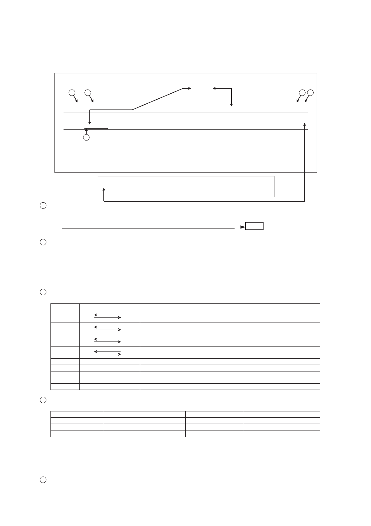
Directions for the Parts Catalog.
1.The parts stipulated in this Parts Catalog are not necessarily standard equipped parts.
2.Parts may change without prior notice.
3.The following is an example of the Parts Catalog format.
1
Ref. No.
0CF10-G21601
1
29. FUEL INJECTION PUMP(W/BOOST)
(A)=4JH-DT
2
LEV.REF. PARTS NO. DESCRIPTION
(A=E00185) (B=E00200)
4
(A=E00156) (B=E00156) (C=E00156) (D=E00156) (E=E00156)
Remarks
(1) BOOST COMPEMSATOR TYPE. OPTIONAL
PART, TO E00155,(4
SCREW M 6X 1626022-06016223 99999
SCREW M 6X 1626022-06016223-1 K44444
CAMSHAFT129470-5104024 11111
BEARING, ROLLER122710-5105025 22222
RETAINER129470-5106026 11111
JH-DT, 4JH-DTZ
(B)=4JH-DTZ
(C)=4JH-DTZP
The Ref. No. listed may not be in accordance with the illustration Ref. No.
(Ex.) Illustration No. List Ref No.
1 1 (Before change)
For interchangeable symbols N, R and K, illustrations for new parts may be abbreviated.
2
Lev. (Level)
Level indication
The numbers below indicate the level of relativity towards the main part.
1 ----- Main parts (Assembly parts)
2 ----- Sub component included in ” 1 ”.
3 ----- Sub component included in ” 2 “.
Note) Parts that are not for sale are partially illustrated but not listed.
(D)=4JH-DTZA
(E)=4JH-DTZY
(F)=
Q'TY
(After change)
1- 1
3
5
RI
(F)(D)(C)(B)(A) (E)
1FUEL INJECTION PUMP729595-5139011 11111
1FUEL INJECTION PUMP729595-5139111-1 N11111
3
Interchangeability Mark
When a part change takes place, one of the following interchangeability symbols is indicated beside the part.
Contents noteInterchangeabilitySymbol
N
Q
R
S
W
Z
F
K
4
Effective Machine No.
Old
Yes
No
No
Yes
Yes
Yes
No
No
New Part is interchangeable for Old Part but Old Part is not interchangeable
NewOld
for New Part.
New Part is not interchangeable for Old Part but Old Part is interchangeable
New
for New Part.
NewOld
New/ Old Parts are both interchangeable.
NewOld
New/ Old Parts are both not interchangeable.
Part newly added.
Part discontinued.
Not interchangeable by a single part but interchangeable together with related
parts.
Changes only for used parts quantities.
When a part changes, the effective Machine No. will be indicated in the (A)-(F) column.
Product Symbol Product No. Product Symbol Product No.
C Clutch No. Compressor No.
.oNevirDD
E Engine No.
F
M
Machine No.
Machine No.
(Agricultural Equip.)
Note 1) A date may follow the symbol. (Ex.) 1996.01
Note 2) ” XXXXX ” and ” ZZZZZ ” are for parts that could not be predicted or for engine models that could
not be identified.
Note 3) (A=E00185) is the E (Engine Serial Number) for the column (A) model (in this case 4JH-DT) after
the parts design change.
5
Remarks Mark
Figures or alphabets (symbols) are entered in the remarks column.
The comments (remarks) on parts that are indicated at the bottom of the illustration are the same symbols as
those stated above.
Page 4

4TNV98-ZSSU
CYLINDER BLOCK 1.
GEAR HOUSING 2.
FLYWHEEL HOUSING & OIL SUMP 3.
CYLINDER HEAD & BONNET 4.
SUCTION MANIFOLD & AIR CLEANER 5.
EXHAUST MANIFOLD & SILENCER 6.
CAMSHAFT & DRIVING GEAR 7.
CRANKSHAFT & PISTON 8.
LUB.OIL SYSTEM 9.
COOLING WATER SYSTEM 10.
FUEL INJECTION PUMP 11.
GOVERNOR 12.
Contents
Fig. No. Fig. Name Fig. No. Fig. Name
FUEL INJECTION VALVE 13.
FUEL LINE 14.
STARTING MOTOR 15.
GENERATOR 16.
ELECTRONIC CONTROL UNIT (ECU) 17.
GASKET SET & TOOLS 18.
Page 5
0CW10-M56100
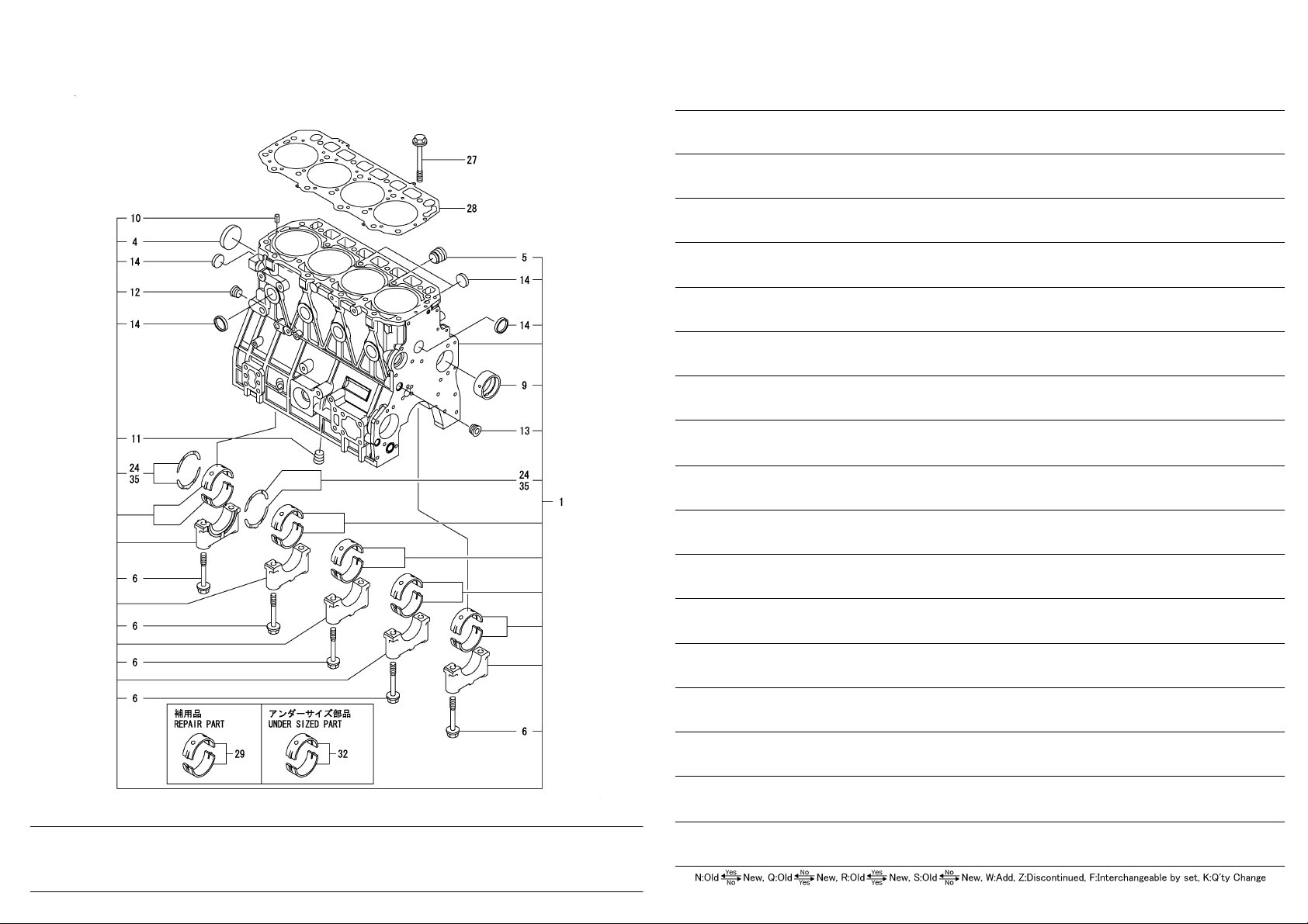
Fig.1. CYLINDER BLOCK
Lev. No. Parts No. Description
BLOCK ASSY , CYLINDER 729927-01560 1 1 1
PLUG, 55 129900-01250 2 4 1
PLUG, NPTF1 171051-01921 2 5 1
BOLT, METAL CAP 129900-02020 2 6 10
BUSH, CAMSHAFT 129900-02410 2 9 1
PIN, SPRING 6.0X12 22351-060012 2 10 2
PLUG, R03 23876-030000 2 11 1
PLUG, R03 23876-030000 2 12 1
PLUG, R03 23876-030000 2 13 1
PLUG 30 27241-300000 2 14 8
BEARING, THRUST 129900-02931 2 24 2
BOLT, HEAD 129900-01200 1 27 18
GASKET, HEAD 129907-01331 1 28 1
(A)=4TNV98-ZSSU
(B)=
(C)=
0CW10-M56100 Fig.1
(D)=
(E)=
(F)=
Q'ty
(F) (D) (C) (B) (A) (E)
R I
1 BEARING, MAIN 729900-02801 1 29 5
2 BEARING, 0.25 US 129900-02341 1 32 5
3 BEARING, THRUST 0.25 129900-02941 1 35 2
Remarks
(1)REPAIR PART.
(2)UNDER SIZED(U.S.=0.25)PART.
(3)OVER SIZED(O.S.=0.25)PART.
Copyright (C) YANMAR CO., LTD. All RightsReserved.
Page 6
0CW10-M56100
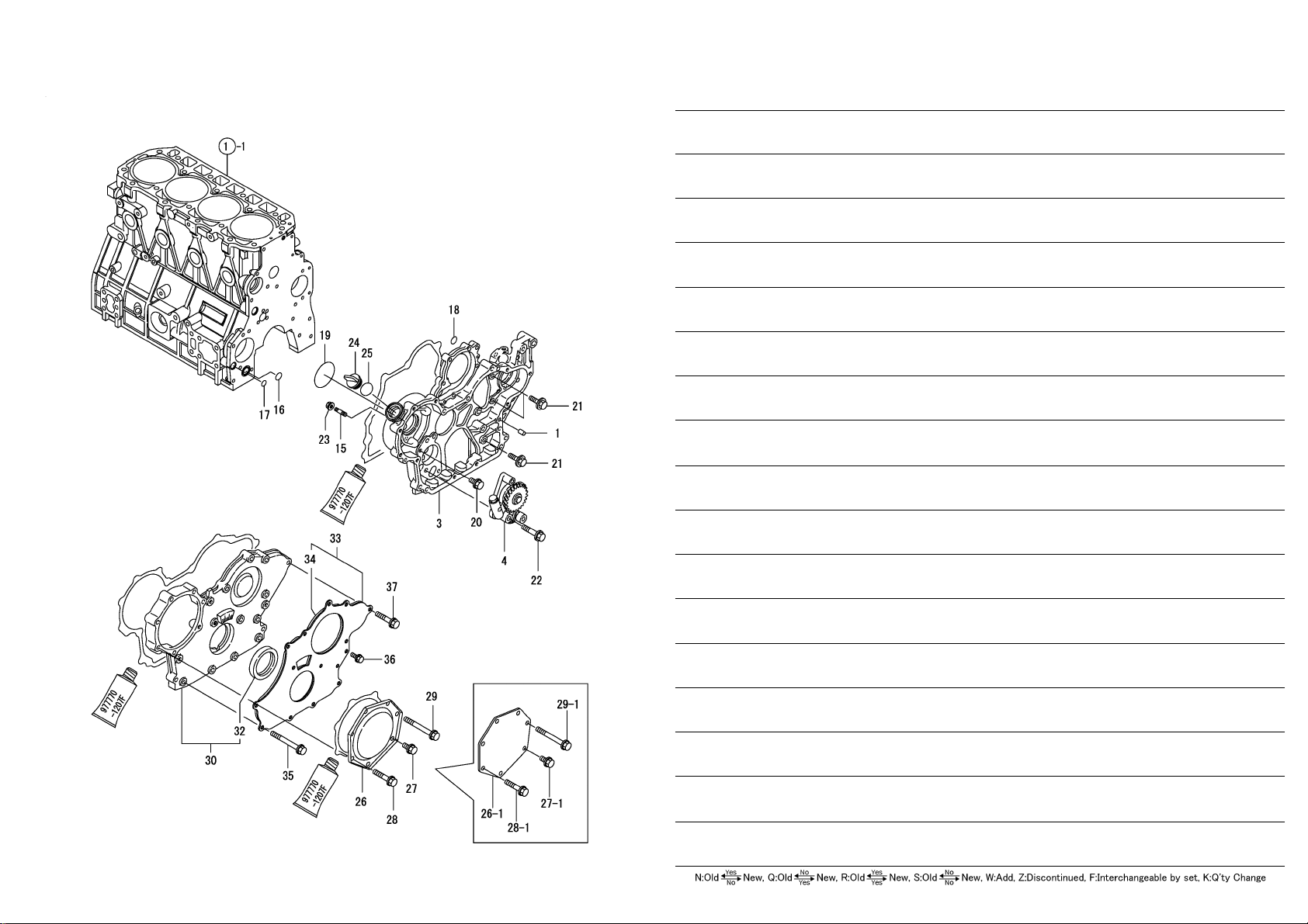
Fig.2. GEAR HOUSING
Lev. No. Parts No. Description
PIN, M8X16 129100-01580 1 1 4
CASE, GEAR 129944-01500 1 3 1
PUMP ASSY, OIL 129900-32001 1 4 1
STUD, M10X 30 26216-100302 1 15 4
O-RING, P20 129900-32030 1 16 1
O-RING, P14 129900-32040 1 17 1
O-RING, 1AP7.0 24311-000070 1 18 1
O-RING, 1A3075 24351-030750 1 19 1
BOLT, M8X 16 PLATED 26106-080162 1 20 1
BOLT, M8X 20 PLATED 26106-080202 1 21 3
BOLT, M8X 45 PLATED 26106-080452 1 22 3
NUT, M10 26306-100002 1 23 4
COVER, FILLER 124160-01751 1 24 1
O-RING, 1AP32.0 24311-000320 1 25 1
COVER 129900-01740 1 26 1
COVER 129951-01740 1 26-1 N 1
(A=EXXXXX)
BOLT, M8X 16 PLATED 26106-080162 1 27 1
BOLT, M8X 20 PLATED 26106-080202 1 27-1 N 1
(A=EXXXXX)
BOLT, M8X 40 PLATED 26106-080402 1 28 5
BOLT, M8X 45 PLATED 26106-080452 1 28-1 N 5
(A=EXXXXX)
BOLT, M8X 70 PLATED 26106-080702 1 29 1
BOLT, M8X 75 PLATED 26106-080752 1 29-1 N 1
(A=EXXXXX)
COVER ASSY ,GEAR CASE 729906-01550 1 30 1
SEAL, OIL 129916-01800 2 32 1
COVER ASSY ,GEAR CASE 129900-01850 1 33 1
SPONGE 129900-01870 2 34 1
BOLT, M8X 70 PLATED 26106-080702 1 35 6
BOLT, M8X 16 PLATED 26106-080162 1 36 3
BOLT, M8X 40 PLATED 26106-080402 1 37 5
(A)=4TNV98-ZSSU
(B)=
(C)=
0CW10-M56100 Fig.2
(D)=
(E)=
(F)=
Q'ty
(F) (D) (C) (B) (A) (E)
R I
Copyright (C) YANMAR CO., LTD. All RightsReserved.
Page 7
0CW10-M56100
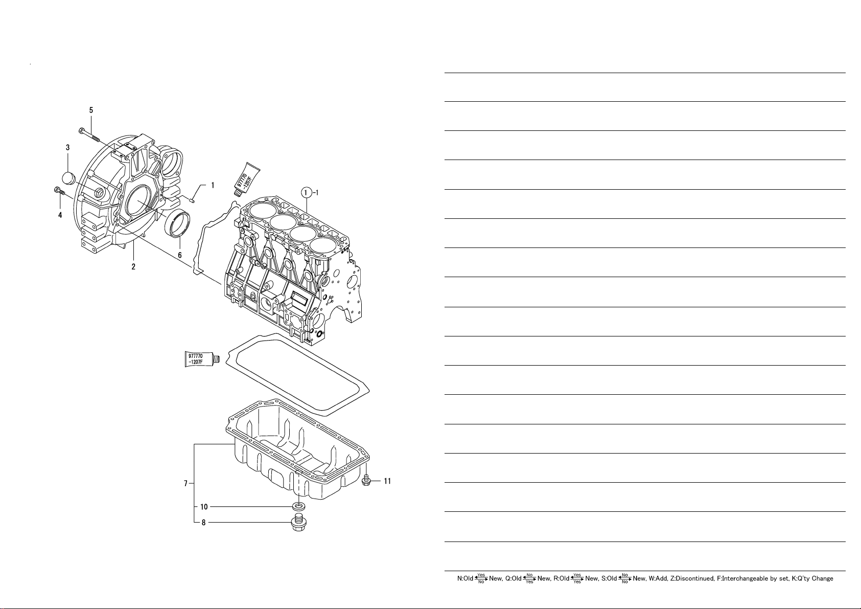
Fig.3. FLYWHEEL HOUSING & OIL SUMP
Lev. No. Parts No. Description
PIN, M8X16 129100-01580 1 1 2
HOUSING, FLYWHEEL 129900-01620 1 2 1
CAP 119620-01750 1 3 1
BOLT, M10X 35 PLATED 26206-100352 1 4 9
BOLT, M10X 70 PLATED 26206-100702 1 5 4
SEAL, D115/95XT11 129916-01790 1 6 1
SUMP ASSY, OIL 129916-01710 1 7 1
PLUG, DRAIN M22 119640-01640 2 8 1
WASHER, SEAL 22 22190-220002 2 10 1
BOLT, M8X 12 PLATED 26106-080122 1 11 16
(A)=4TNV98-ZSSU
(B)=
(C)=
0CW10-M56100 Fig.3
(D)=
(E)=
(F)=
Q'ty
(F) (D) (C) (B) (A) (E)
R I
Copyright (C) YANMAR CO., LTD. All RightsReserved.
Page 8

0CW10-M56100
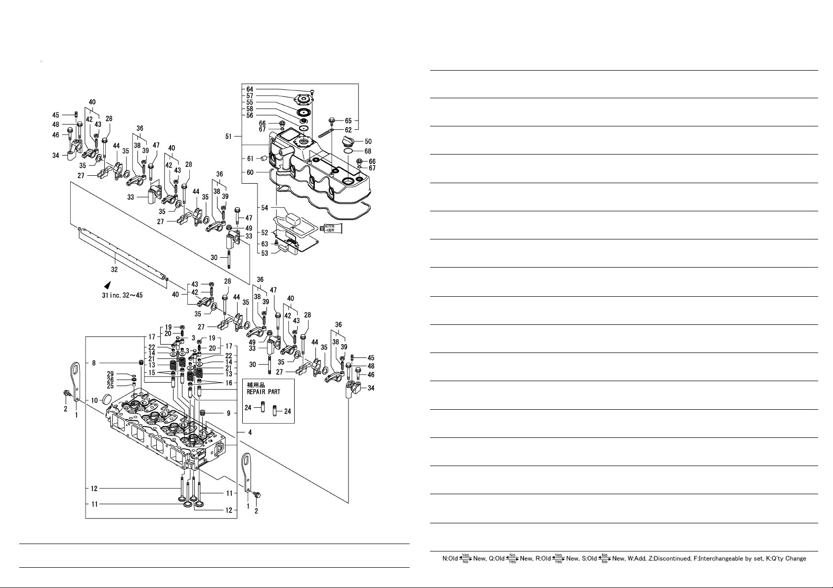
Fig.4. CYLINDER HEAD & BONNET
Remarks
(1)REPAIR PART.
Lev. No. Parts No. Description
++ CONTINUE ++
(A)=4TNV98-ZSSU
(B)=
(C)=
LIFTER 129907-07900 1 1 2
BOLT, M8X 16 PLATED 26106-080162 1 2 4
SEAT, VALVE BRIDGE 123907-11550 1 3 8
HEAD ASSY, CYLINDER 129927-11700 1 4 1
PLUG, R02 23876-020000 2 8 1
PLUG, R03 23876-030000 2 9 4
PLUG, 40 27241-400000 2 10 1
VALVE, INTAKE 129907-11100 2 11 8
VALVE, EXHAUST 129907-11110 2 12 8
SPRING, VALVE 129907-11120 2 13 16
RETAINER, SPRING 119620-11180 2 14 16
SEAL, VALVE STEM 119803-11340 2 15 8
SEAL, VALVE STEM 124160-11340 2 16 8
BRIDGE ASSY , V AL VE 129907-11510 2 17 8
NUT, M8 129150-11750 3 19 8
ADJUSTER 123907-11830 3 20 8
GUIDE 123907-11820 2 21 8
COTTER, 7 27310-070001 2 22 16
PROTECTOR, NOZZLE 119802-11870 1 25 4
SEAT, NOZZLE 119625-11880 1 26 4
RETAINER, NOZZLE 129907-11910 1 27 4
BOLT, M8X75 129907-11950 1 28 4
O-RING, 1AP12.0 24311-000120 1 29 4
STUD, M8X80 119593-11301 1 30 2
SHAFT ASSY, ROCKER 129907-11341 1 31 1
SHAFT, ROCKER ARM 129907-11250 2 32 1
SUPPORT, ROCKER ARM 129907-11260 2 33 3
SUPPORT, ROCKER ARM 129907-11270 2 34 2
WASHER 123907-11280 2 35 8
ARM, ROCKER 129907-11650 2 36 4
SCREW, VALVE ADJUST 129150-11230 3 38 4
NUT, M8 129150-11750 3 39 4
ARM, ROCKER 129907-11660 2 40 4
SCREW, VALVE ADJUST 129150-11230 3 42 4
NUT, M8 129150-11750 3 43 4
RETAINER 129907-11920 2 44 4
STUD, M8X 22 26226-080222 2 45 2
BOLT, M8X 40 PLATED 26106-080402 1 46 2
BOLT, M8X 60 PLATED 26106-080602 1 47 4
BOLT, M8X 60 PLATED 26106-080602 1 48 2
NUT, M8 26306-080002 1 49 2
COVER, FILLER 124160-01751 1 50 1
BONNET ASSY, HEAD 129927-11320 1 51 1
PLATE 129907-03011 2 52 1
BAFFLE, BREATHER 129907-03061 2 53 1
BAFFLE, BREATHER 129907-03070 2 54 1
DIAPHRAGM 123907-03100 2 55 1
PLATE 123907-03110 2 56 1
PLATE, BREATHER 123907-03120 2 57 1
SPRING, DIAPHRAGM 123907-03140 2 58 1
Copyright (C) YANMAR CO., LTD. All RightsReserved.
0CW10-M56100 Fig.4
(D)=
(E)=
(F)=
Q'ty
(F) (D) (C) (B) (A) (E)
R I
1 GUIDE, VALVE 129907-11800 1 24 16
Page 9
0CW10-M56100
Fig.4. CYLINDER HEAD & BONNET
Lev. No. Parts No. Description
GASKET, BONNET 129933-11310 2 60 1
PLUG 119640-61400 2 61 1
CLIP 175339-79700 2 62 2
SCREW, 5X10 22857-500100 2 63 6
SCREW, 5X10 22857-500100 2 64 6
BOLT, M6X 12 PLATED 26106-060122 2 65 2
KNOB 124160-11360 1 66 4
O-RING, 1AP12.0 24311-000120 1 67 4
O-RING, 1AP32.0 24311-000320 1 68 1
(A)=4TNV98-ZSSU
(B)=
(C)=
0CW10-M56100 Fig.4
(D)=
(E)=
(F)=
Q'ty
(F) (D) (C) (B) (A) (E)
R I
Remarks
(1)REPAIR PART.
Copyright (C) YANMAR CO., LTD. All RightsReserved.
Page 10

0CW10-M56100
Fig.5. SUCTION MANIFOLD & AIR CLEANER
Lev. No. Parts No. Description
GASKET, MANIFOLD 129907-12110 1 1 1
MANIFOLD ASSY ,INTAKE 129927-12150 1 2 1
MANIFOLD, AIR INTAKE 129927-12100 2 3 1
STUD, M6X 20 26216-060202 2 4 2
BOLT, M8X 45 PLATED 26106-080452 1 5 6
BOLT, M8X 80 PLATED 26106-080802 1 6 4
GASKET 119129-77020 1 7 1
GASKET 121850-77021 1 8 1
HEATER 119005-77051 1 9 1
BEND 119129-77520 1 10 1
BOLT, M8X 40 PLATED 26106-080402 1 11 2
BOLT, M8X 90 PLATED 26106-080902 1 12 2
PIPE, AIR INTAKE 129927-12060 1 13 1
CLEANER ASSY, AIR 129935-12500 1 14 1
BODY 129935-12510 2 15 1
ELEMENT 129935-12520 2 16 1
COVER ASSY 119160-12530 2 17 1
VALVE 119160-12540 2 18 1
ELEMENT 119160-12570 2 19 1
INDICATOR 119140-12680 2 20 1
BRACKET , AIR CLEANER 129949-12560 1 21 1
CLAMP, 80 23000-080000 1 22 1
CLAMP, 90 23000-090000 1 23 1
BOLT, M8X 22 26013-080222 1 24 4
BOLT, M8X 22 26013-080222 1 25 2
ELEMENT, OUTER 119160-12560 1 26 1
ELEMENT 119160-12570 1 27 1
(A)=4TNV98-ZSSU
(B)=
(C)=
0CW10-M56100 Fig.5
(D)=
(E)=
(F)=
Q'ty
(F) (D) (C) (B) (A) (E)
R I
Copyright (C) YANMAR CO., LTD. All RightsReserved.
Page 11

0CW10-M56100
Fig.6. EXHAUST MANIFOLD & SILENCER
Lev. No. Parts No. Description
MANIFOLD ASSY 129927-13150 1 1 1
MANIFOLD, EXHAUST 129927-13100 2 2 1
STUD, M8X20 129418-18320 2 3 2
STUD, M8X22 119131-18320 2 4 4
GASKET 129900-13251 1 5 1
BOLT, M8X90 10.9T 119802-13680 1 6 6
STUD, M8X90 129263-13210 1 7 2
NUT, M8 26306-080002 1 8 2
PIPE ASSY 129927-13800 1 9 1
GASKET 129927-13810 1 10 1
BOLT, M10X 30 PLATED 26106-100302 1 11 2
NUT, M8 26306-080002 1 12 2
VALVE 129928-13900 1 13 1
GASKET 129927-13910 1 14 1
GASKET 129927-13920 1 15 1
BOLT, M10X 30 PLATED 26106-100302 1 16 1
BOLT, M10X 95 PLATED 26106-100952 1 17 1
GASKET, SILENCER 129930-13201 1 18 1
SILENCER 129907-13500 1 19 1
BRACKET, SILENCER 129927-13550 1 20 1
BOLT, M8X 20 PLATED 26106-080202 1 21 2
STUD, M8X 40 26216-080402 1 22 2
NUT, M8 26306-080002 1 23 4
NUT, M8 26306-080002 1 24 2
GASKET, SILENCER 129930-13201 1 25 1
(A)=4TNV98-ZSSU
(B)=
(C)=
0CW10-M56100 Fig.6
(D)=
(E)=
(F)=
Q'ty
(F) (D) (C) (B) (A) (E)
R I
Copyright (C) YANMAR CO., LTD. All RightsReserved.
Page 12

0CW10-M56100
Fig.7. CAMSHAFT & DRIVING GEAR
Lev. No. Parts No. Description
TAPPET 129150-14200 1 1 8
ROD, PUSH 129907-14400 1 2 8
CAMSHAFT ASSY 129908-14581 1 3 1
BEARING, THRUST 129150-02450 2 4 1
GEAR, CAMSHAFT 129900-14100 2 6 1
KEY, 7X 14 22512-070140 2 7 1
BOLT, M8X 16 PLATED 26106-080162 1 8 2
SHAFT, IDLE GEAR 123900-25060 1 9 1
GEAR ASSY , IDLE 129900-25100 1 10 1
BOLT, M8X 55 PLATED 26106-080552 1 14 3
BOLT 129953-25300 1 15 4
GEAR, PUMP 129907-25900 1 16 1
(A)=4TNV98-ZSSU
(B)=
(C)=
0CW10-M56100 Fig.7
(D)=
(E)=
(F)=
Q'ty
(F) (D) (C) (B) (A) (E)
R I
1 BUSH, IDLE GEAR 129150-25920 1 13 1
Remarks
(1)REPAIR PART.
Copyright (C) YANMAR CO., LTD. All RightsReserved.
Page 13

Y
0CW10-M56100
Fig.8. CRANKSHAFT & PISTON
(A)=4TNV98-ZSSU
(B)=
(C)=
Lev. No. Parts No. Description
CRANKSHAFT ASSY 129902-21000 1 1 1
GEAR, CRANKSHAFT 129900-21200 2 3 1
PIN 121850-21290 2 4 1
PIN, M10X22 121850-21920 2 5 1
KEY, 7X 14 22512-070140 2 6 1
BOLT 129916-21610 1 7 1
129916-21680 1 8 1
V-PULLE
WASHER 129960-21640 1 9 1
O-RING, 1AS53.0 24341-000530 1 10 1
BOLT, FLYWHEEL 121850-21130 1 11 6
FLY WHEEL ASSY 129916-21590 1 12 1
GEAR, RING 129900-21600 2 14 1
PISTON ASSY 129927-22080 1 15 4
RING SET, PISTON 129927-22050 2 17 4
PIN, PISTON 120130-22301 1 21 4
RING, 30 22252-000300 1 22 8
ROD ASSY , CONNECTING 129900-23001 1 23 4
BOLT, CONNECTING ROD 129900-23200 2 26 8
BEARING, CRANK PIN 129900-23601 2 27 4
0CW10-M56100 Fig.8
(D)=
(E)=
(F)=
Q'ty
(F) (D) (C) (B) (A) (E)
R I
1 BEARING, PISTON PIN 129900-23911 1 29 4
2 BEARING, 0.25 US 129900-23611 1 30 4
3 PISTON ASSY, 0.25 OS 729927-22900 1 32 4
3 RING SET, 0.25 OS 729927-22950 2 34 4
Remarks
(1)REPAIR PART.
(2)UNDER SIZED(U.S.=0.25)PART.
(3)OVER SIZED(O.S.=0.25)PART.
Copyright (C) YANMAR CO., LTD. All RightsReserved.
Page 14

0CW10-M56100
Fig.9. LUB.OIL SYSTEM
Lev. No. Parts No. Description
GUIDE, DIPSTICK 121520-34810 1 1 1
DIPSTICK, OIL 129906-34851 1 2 1
BOLT, FILTER 119000-35140 1 3 1
O-RING, P20 129900-32030 1 5 1
PIPE ASSY, OIL INLET 129953-35000 1 6 1
BOLT, M8X 12 PLATED 26106-080122 1 11 1
BOLT, M8X 16 PLATED 26106-080162 1 12 1
SWITCH, 0.5KG 119761-39450 1 13 1
PIPE ASSY, OIL 129927-39060 1 14 1
RETAINER 123907-39500 2 16 1
BOLT ASSY, JOINT M8 129005-59830 1 18 2
WASHER, SEAL 6 22190-080002 2 19 2
BOLT, JOINT 3 23857-030000 2 20 2
WASHER, SEAL 6 22190-080002 1 21 2
BOLT, M8X 12 PLATED 26106-080122 1 22 1
WASHER, SEAL 6 22190-080002 1 23 2
BOLT, M8X 12 PLATED 26106-080122 1 24 2
FILTER, D80X100L 119005-35151 1 25 1
(A)=4TNV98-ZSSU
(B)=
(C)=
0CW10-M56100 Fig.9
(D)=
(E)=
(F)=
Q'ty
(F) (D) (C) (B) (A) (E)
R I
1 FILTER, D80X100L 119005-35151 1 4 1
Remarks
(1)REPAIR PART.
Copyright (C) YANMAR CO., LTD. All RightsReserved.
Page 15

Y
0CW10-M56100
Fig.10. COOLING WATER SYSTEM
(A)=4TNV98-ZSSU
(B)=
(C)=
Lev. No. Parts No. Description
PUMP ASSY, WATER 129927-42000 1 1 1
GASKET, WATER PUMP 129900-42020 1 11 1
BOLT, M6X 30 PLATED 26106-060302 1 12 2
BOLT, M8X 55 PLATED 26106-080552 1 13 5
129900-42461 1 14 1
V-PULLE
V-BEL T, A41 25152-004100 1 15 1
SPACER, FAN 119117-44760 1 16 1
BOLT, M8X 80 PLATED 26106-080802 1 17 4
CASE ASSY,THERMOSTAT 129927-49800 1 18 1
SENSOR 129927-44900 2 19 1
COVER, THERMOSTAT 129916-49530 2 21 1
GASKET , THERMOSTA T 121850-49540 2 23 1
GASKET , THERMOSTA T 121850-49550 2 24 1
THERMOSTAT, 71 121850-49810 2 25 1
WASHER, SEAL 12 22190-120002 2 27 1
PLUG, R03 23875-030000 2 28 2
BOLT, M6X 20 PLATED 26106-060202 2 29 4
GASKET 129900-49870 1 30 1
GASKET, 8X1.0 23414-080000 1 31 1
BOLT, M8X 12 PLATED 26106-080122 1 32 1
BOLT, M8X 60 PLATED 26106-080602 1 33 3
PLUG, DRAIN 171056-49120 1 34 1
PLUG, M16 121450-42450 1 35 2
GASKET, 16 124465-44950 1 36 2
PIPE, WATER 129927-49610 1 37 1
CLAMP, 12 23080-012000 2 40 2
PIPE ASSY, WATER 129927-49620 1 41 1
CLAMP, 12 23080-012000 2 44 2
FAN, COOLING D=460 129953-44710 1 45 1
0CW10-M56100 Fig.10
(D)=
(E)=
(F)=
Q'ty
(F) (D) (C) (B) (A) (E)
R I
Copyright (C) YANMAR CO., LTD. All RightsReserved.
Page 16

Y
Y
0CW10-M56100
Fig.11. FUEL INJECTION PUMP
Remarks
(1)GOVERNOR ASSY(FIG.12) IS
INCORPORATED IN THIS FOP.CMP
(REF.NO.1).
* ECO PUMP
MAKE SURE TO UPDATE THE ENGINES
ECU INFORMATION WHEN REPLACING
THE ECO PUMP.
FAILING TO DO SO WILL RESULT IN
ENGINE MALFUNCTION.
(A)=4TNV98-ZSSU
(B)=
(C)=
Lev. No. Parts No. Description
KEY, 5X19 144626-51090 2 9 1
FLANGE 158563-51150 2 12 1
STOPPER, TAPPET 158600-51270 2 18 1
O-RING, 4D S6 158563-51281 2 19 1
O-RING, 4D S6 158563-51281 2 20 1
129927-51390 2 21 4
VALVE ASSY, DELIVER
SPRING, DELIVERY 158563-51330 3 30 4
PLUG 158601-51550 2 52 1
PLUG, BARREL 129907-51560 2 53 1
GASKET 158552-51571 2 54 4
PLUG 158557-51570 2 55 1
GASKET 129906-51580 2 56 1
LIFTER 158552-51580 2 57 1
TIMER SET 129657-51590 2 58 1
TIMER ASSY 129657-51600 3 59 1
O-RING, 1011 158553-51670 3 62 1
RING, BACK UP 119802-51680 3 63 1
O-RING 119802-51690 3 64 1
O-RING, 4D1020 24356-010200 3 65 1
RING, BACK UP T2P15 24372-000150 3 66 1
GASKET 158560-51600 2 67 1
SPRING, TIMER 119852-51630 2 68 1
CAP 119852-51640 2 69 1
119852-51650 2 71 1
VALVE ASS
GASKET 158553-51680 2 74 1
PISTON 158601-51770 2 95 1
SPRING 158552-51781 2 96 1
PLUG 158601-51790 2 97 1
WASHER, SEAL 12 22190-120002 2 98 1
WASHER, SEAL 18 22190-180002 2 99 1
PLUG, M12 158553-51930 2 100 1
O-RING 158552-52311 2 102 1
O-RING, 4E S42 158552-52400 2 103 1
NUT, LOCK M18 26776-180002 2 104 1
WASHER, SEAL 12 22190-120002 2 105 2
WASHER, SPRING 18 22217-180000 2 106 1
PIN, PARALLEL M5X14 22312-050140 2 107 2
PIN, SPRING 5.0X10 22351-050010 2 108 2
O-RING, 1AP7.0 24311-000070 2 109 1
O-RING, 4D1020 24356-010200 2 110 1
O-RING, 4D2021 24356-020210 2 111 1
BOLT, M6X 10 PLATED 26106-060102 2 112 1
BOLT, M6X 35 PLATED 26106-060352 2 113 4
BOLT, M10X 45 26450-100452 2 116 4
PLUG, 16 27241-160000 2 117 1
HARNESS ASSY, WIRE 129927-51650 2 120 1
HARNESS ,CSD 129927-51660 3 121 1
CAP, RUBBER 129263-77941 3 122 1
JOINT, OVER FLOW 158601-51650 2 123 1
BRACKET 129927-51670 2 124 1
0CW10-M56100 Fig.11
(D)=
(E)=
(F)=
Q'ty
(F) (D) (C) (B) (A) (E)
R I
1 PUMP ASSY, INJECTION 729921-51330 1 1 1
++ CONTINUE ++
Copyright (C) YANMAR CO., LTD. All RightsReserved.
Page 17

0CW10-M56100
Fig.11. FUEL INJECTION PUMP
Lev. No. Parts No. Description
JOINT, OVER FLOW 158552-51670 2 125 1
PUMP ASSY, FUEL FEED 158552-52100 2 127 1
O-RING 158552-52500 3 128 1
JOINT, PIPE 119934-59910 2 129 1
WASHER, SEAL 12 22190-120002 2 130 1
WASHER, SPRING 5 22217-050000 2 131 1
BOLT, M6X 12 PLATED 26106-060122 2 132 1
NUT, M5 26716-050002 2 133 1
RETAINER, PUMP 129927-51250 1 135 1
BOLT, M8X 20 PLATED 26106-080202 1 136 3
BOLT, M8X 30 PLATED 26106-080302 1 137 3
(A)=4TNV98-ZSSU
(B)=
(C)=
0CW10-M56100 Fig.11
(D)=
(E)=
(F)=
Q'ty
(F) (D) (C) (B) (A) (E)
R I
Remarks
(1)GOVERNOR ASSY(FIG.12) IS
INCORPORATED IN THIS FOP.CMP
(REF.NO.1).
* ECO PUMP
MAKE SURE TO UPDATE THE ENGINES
ECU INFORMATION WHEN REPLACING
THE ECO PUMP.
FAILING TO DO SO WILL RESULT IN
ENGINE MALFUNCTION.
Copyright (C) YANMAR CO., LTD. All RightsReserved.
Page 18

0CW10-M56100
Fig.12. GOVERNOR
Lev. No. Parts No. Description
GASKET 158560-61050 2 2 1
NUT 129008-61301 2 19 1
SENSOR 158557-61720 2 22 1
GEAR, SENSOR 158553-61780 2 23 1
WASHER, SEAL 12 22190-120000 2 24 1
PLUG, M12 158553-51930 2 25 1
O-RING, 1AS48.0 24341-000480 2 26 1
BOLT, M6X 16 PLATED 26106-060162 2 27 1
BOLT, M8X 25 PLATED 26106-080252 2 28 3
BOLT, M8X 25 PLATED 26106-080252 2 29 10
(A)=4TNV98-ZSSU
(B)=
(C)=
0CW10-M56100 Fig.12
(D)=
(E)=
(F)=
Q'ty
(F) (D) (C) (B) (A) (E)
R I
Remarks
* THIS FIGURE(GOVERNOR ASSY)IS
INCORPORATED IN THE FUEL INJECTION
PUMP ASSY(FIG.1 1).
Copyright (C) YANMAR CO., LTD. All RightsReserved.
Page 19

0CW10-M56100
Fig.13. FUEL INJECTION VALVE
Lev. No. Parts No. Description
VALVE ASSY,INJECTION 729927-53200 1 1 4
NUT, NOZZLE D16.95 114250-53080 2 2 4
SPRING, NOZZLE 114250-53120 2 6 4
SEAT, SPRING 114250-53130 2 7 4
PLATE 114250-53140 2 8 4
VALVE ASSY,INJECTION 129927-53200 2 9 4
PIN 114250-53210 2 12 8
SHIM SET 119803-53400 2 13 4
SEAL 123907-11601 1 40 4
RETAINER, PIPE 123472-59120 1 41 2
RETAINER, PIPE 129150-59120 1 42 1
BOLT, M4X14 129150-59131 2 45 2
PIPE ASSY, INJECTION 129927-59810 1 47 1
PIPE ASSY, INJECTION 129927-59820 1 48 1
PIPE ASSY, INJECTION 129927-59830 1 49 1
PIPE ASSY, INJECTION 129927-59840 1 50 1
NUT, M6 26366-060002 1 51 2
(A)=4TNV98-ZSSU
(B)=
(C)=
0CW10-M56100 Fig.13
(D)=
(E)=
(F)=
Q'ty
(F) (D) (C) (B) (A) (E)
R I
Copyright (C) YANMAR CO., LTD. All RightsReserved.
Page 20

0CW10-M56100
Fig.14. FUEL LINE
Lev. No. Parts No. Description
BRACKET, FILTER 129004-55612 1 1 1
FILTER, FUEL 129907-55801 1 2 1
BOLT, M8X 30 PLATED 26106-080302 1 3 2
PIPE ASSY, FUEL 129457-59010 1 4 1
CLIP, HOSE 12 124766-59050 2 5 2
TUBE, CORRUGATED 129957-59120 2 6 1
PIPE, FUEL 105025-59750 2 7 1
PIPE ASSY, FUEL 129961-59310 1 8 1
CLIP, HOSE 12 124766-59050 2 9 2
PIPE, D13/7.5X270 129136-59110 2 10 1
TUBE, CORRUGATED 129961-59110 2 11 1
BAND, 140 121750-59890 1 12 1
PIPE ASSY, RETURN 129907-59140 1 13 1
BOLT, PIPE JOINT M6 123907-59540 1 14 5
GASKET 123907-59550 1 15 5
PIPE ASSY, RETURN 129927-59550 1 16 1
TUBE, CORRUGATED 129263-49750 2 17 1
CLIP, HOSE 9 124722-59050 2 18 2
JOINT 123907-59560 1 20 1
WASHER, SEAL 6 22190-080002 1 21 1
LABEL, FUEL OIL NOTI 114110-07760 1 22 1
PUMP ASSY, FUEL FEED 119225-52102 1 23 1
SEPARATOR ASSY 129242-55700 1 24 1
CUP 129242-55720 2 25 1
ELEMENT 129242-55730 2 26 1
PLUG, DRAIN 129242-55740 2 27 1
VALVE, AIR VENT 129242-55750 2 28 1
GASKET 129242-55760 2 29 1
FLOAT 129242-55770 2 30 1
O-RING, 1AP16.0 24311-000160 2 31 1
O-RING, 1AG75.0 24321-000750 2 32 1
FILTER, FUEL 129907-55801 1 33 1
(A)=4TNV98-ZSSU
(B)=
(C)=
0CW10-M56100 Fig.14
(D)=
(E)=
(F)=
Q'ty
(F) (D) (C) (B) (A) (E)
R I
Copyright (C) YANMAR CO., LTD. All RightsReserved.
Page 21

Y
0CW10-M56100
Fig.15. STARTING MOTOR
(A)=4TNV98-ZSSU
(B)=
(C)=
Lev. No. Parts No. Description
STARTER 12V,3KW 129940-77010 1 1 1
129940-77100 2 2 1
ARMATURE ASS
COIL ASSY, FIELD 129940-77130 2 5 1
SCREW, POLE CORE SET 129940-77140 3 6 4
O-RING 129940-77150 3 7 1
BRUSH (+) 129940-77160 3 8 2
COVER, REAR 129940-77170 2 9 1
HOLDER, BRUSH 129940-77180 2 10 1
SPRING, BRUSH 129940-77190 3 11 1
BRUSH (-) 129940-77200 3 12 2
SWITCH ASSY ,MAGNETIC 129940-77210 2 13 1
HOUSING, GEARS 129940-77220 2 14 1
RETAINER, BEARING 129940-77230 2 15 1
SHIFT LEVER SET 129940-77240 2 16 1
COVER ASSY , DUST 129940-77250 2 17 1
THROUGHT BOLT 129940-77260 2 18 2
BOLT M6X 20 129940-77270 2 19 4
SCREW M4X 10 129940-77280 2 20 2
PINION ASSY 123900-77510 2 21 1
CLUTCH ASSY 123900-77520 3 22 1
BALL BEARING (3 X2240610100 4 23 2
SHAFT, PINION 123900-77540 3 24 1
STOPPER KIT, PINION 119131-77550 3 25 1
COVER, TERMINAL 121254-77810 2 29 1
BOLT M 6X 37 114371-79070 2 30 2
BOLT, M12X 25 PLATED 26116-120252 1 31 2
0CW10-M56100 Fig.15
(D)=
(E)=
(F)=
Q'ty
(F) (D) (C) (B) (A) (E)
R I
Copyright (C) YANMAR CO., LTD. All RightsReserved.
Page 22

0CW10-M56100
Fig.16. GENERATOR
Lev. No. Parts No. Description
STUD 129795-01900 1 1 1
ALTERNATOR, 12V-55A 119626-77210 1 2 1
NUT X9490561001 2 3 1
ROTOR ASSY 129052-77380 2 4 1
BEARING, BALL 123501-79240 3 5 1
COVER, BEARING 119620-79250 3 6 1
FRAME ASSY 129052-77422 2 7 1
BALL BEARING 119620-79200 3 8 1
PLATE, RETAINER 119620-79210 3 9 1
SCREW 11 9620-79220 3 10 4
STUD 119620-79230 3 11 2
FRAME 128401-77440 2 12 1
PULLEY 119620-77461 2 13 1
NUT 119620-77471 2 14 1
COLLAR 119620-77490 2 15 1
REGULATOR ASSY 119626-77710 2 16 1
HOLDER 129052-79260 2 17 1
HOLDER, BRUSH 129052-79270 2 18 1
SCREW 11 9620-79290 2 19 6
SCREW 11 9620-79300 2 20 1
BOLT 119620-79310 2 21 3
SCREW 11 9620-79320 2 22 2
BOLT 119620-79330 2 23 2
BUSH, INSULATION 119620-79340 2 24 1
NUT 119620-79350 2 25 2
COVER, END, RR 119626-77450 2 26 1
NUT, M10 26306-100002 1 27 1
ADJUSTER 129900-77330 1 28 1
BOLT, ADJUSTER 119810-77340 1 29 1
BOLT, M8X 25 26014-080252 1 30 1
RELAY, CA TYPE C 198461-52950 1 31 3
RELAY 129927-77920 1 32 2
WASHER 129927-77690 1 33 3
(A)=4TNV98-ZSSU
(B)=
(C)=
0CW10-M56100 Fig.16
(D)=
(E)=
(F)=
Q'ty
(F) (D) (C) (B) (A) (E)
R I
Copyright (C) YANMAR CO., LTD. All RightsReserved.
Page 23

0CW10-M56100
Fig.17. ELECTRONIC CONTROL UNIT (ECU)
Lev. No. Parts No. Description
SHIELD 129927-77600 2 2 1
COLLAR 129927-77680 2 3 3
ABSORBER 119578-91351 2 4 3
SCREW, 5X 8 22877-500080 2 5 6
SHIELD 129927-77600 2 7 1
COLLAR 129927-77680 2 8 3
ABSORBER 119578-91351 2 9 3
SCREW, 5X 8 22877-500080 2 10 6
(A)=4TNV98-ZSSU
(B)=
(C)=
0CW10-M56100 Fig.17
(D)=
(E)=
(F)=
Q'ty
(F) (D) (C) (B) (A) (E)
R I
1 CONTROLLER ASSY, EUC 129939-75190 1 1 1
2 CONTROLLER ASSY, EUC 129927-75900 1 6 1
Remarks
(1)ECO ECU
THIS PART CANNOT BE ORDERED.
REPLACE THE PART USING A SERVICE
ECU WITH THE PROPER ENGINE
INFORMATION INSTALLED.
(2)SERVICE ECU
IF THE PROPER INFORMATION IS NOT
INSTALLED, THE ENGINE WILL NOT
OPERATE.
TO INSTALL PROPER INFORMATION,
GO TO AN AUTHORIZED DISTRIBUTOR.
Copyright (C) YANMAR CO., LTD. All RightsReserved.
Page 24

0CW10-M56100
Fig.18. GASKET SET & TOOLS
Lev. No. Parts No. Description
GASKET, HEAD 129907-01331 2 2 1
O-RING, P20 129900-32030 2 3 2
O-RING, P14 129900-32040 2 4 1
O-RING, 1AP7.0 24311-000070 2 5 1
O-RING, 1A3075 24351-030750 2 6 1
O-RING, 1AP32.0 24311-000320 2 7 2
GASKET 123907-59550 2 8 5
SEAL, VALVE STEM 119803-11340 2 9 8
SEAL, VALVE STEM 124160-11340 2 10 8
PROTECTOR, NOZZLE 119802-11870 2 11 4
SEAT, NOZZLE 119625-11880 2 12 4
O-RING, 1AP12.0 24311-000120 2 13 8
GASKET, BONNET 129933-11310 2 14 1
GASKET, MANIFOLD 129907-12110 2 15 1
GASKET 119129-77020 2 16 1
GASKET 121850-77021 2 17 1
GASKET 129900-13251 2 18 1
GASKET, SILENCER 129930-13201 2 19 2
GASKET 129927-13810 2 20 1
GASKET 129927-13910 2 21 1
GASKET 129927-13920 2 22 1
O-RING, 1AS53.0 24341-000530 2 23 1
WASHER, SEAL 6 22190-080002 2 24 7
GASKET, WATER PUMP 129900-42020 2 25 1
GASKET , THERMOSTA T 121850-49540 2 26 1
GASKET , THERMOSTA T 121850-49550 2 27 1
WASHER, SEAL 12 22190-120002 2 28 1
GASKET 129900-49870 2 29 1
GASKET, 8X1.0 23414-080000 2 30 1
GASKET, 16 124465-44950 2 31 2
WASHER, SEAL 22 22190-220002 2 32 1
(A)=4TNV98-ZSSU
(B)=
(C)=
0CW10-M56100 Fig.18
(D)=
(E)=
(F)=
Q'ty
(F) (D) (C) (B) (A) (E)
R I
1 GASKET SET 729927-92640 1 1 1
1 GASKET.LIQUID 977770-1207F 1 33 1
1 HONE 129400-92450 1 34 1
Remarks
(1)OPTIONAL PART.
Copyright (C) YANMAR CO., LTD. All RightsReserved.
Page 25

Parts No. Index
Parts No. Fig. No. Ref. No. Parts No. Fig. No. Ref. No. Parts No. Fig. No. Ref. No. Parts No. Fig. No. Ref. No.
105025-59750 714 119640-01640 83 123907-59560 2014 129900-01620 23
114110-07760 2214 119640-61400 614 124160-01751 242 129900-01740 262
114250-53080 213 119761-39450 139 504 129900-01850 332
114250-53120 613 119802-11870 254 124160-11340 164 129900-01870 342
114250-53130 713 1118 1018 129900-02020 61
114250-53140 813 119802-13680 66 124160-11360 664 129900-02341 321
114250-53210 1213 119802-51680 6311 124465-44950 3610 129900-02410 91
114371-79070 3015 119802-51690 6411 3118 129900-02931 241
119000-35140 39 119803-11340 154 124722-59050 1814 129900-02941 351
119005-35151 49 918 124766-59050 514 129900-13251 56
119005-77051 95 119810-77340 2916 128401-77440 1216 129900-14100 67
119117-44760 1610 119852-51630 6811 129004-55612 114 129900-21200 38
119129-77020 75 119852-51640 6911 129005-59830 189 129900-21600 148
119129-77520 105 119934-59910 12911 129052-77380 416 129900-23200 268
119131-18320 46 120130-22301 218 129052-77422 716 129900-23601 278
119131-77550 2515 121254-77810 2915 129052-79260 1716 129900-23611 308
119140-12680 205 121450-42450 3510 129052-79270 1816 129900-23911 298
119160-12530 175 121520-34810 19 129100-01580 12 129900-25100 107
119160-12540 185 121750-59890 1214 13 129900-32001 42
119160-12560 265 121850-21130 118 129136-59110 1014 129900-32030 162
119160-12570 195 121850-21290 48 129150-02450 47 59
119225-52102 2314 121850-49540 2310 42 129900-32040 172
119578-91351 417 2618 129150-11750 194 418
119593-11301 304 2718 43 2518
119620-01750 33 121850-49810 2510 129150-14200 17 129900-42461 1410
119620-11180 144 121850-77021 85 129150-25920 137 129900-49870 3010
119620-77461 1316 1718 129150-59120 4213 2918
119620-77471 1416 123472-59120 4113 129150-59131 4513 129900-77330 2816
119620-77490 1516 123501-79240 516 129242-55700 2414 129902-21000 18
119620-79200 816 123900-25060 97 129242-55720 2514 129906-34851 29
119620-79210 916 123900-77510 2115 129242-55730 2614 129906-51580 5611
119620-79220 1016 123900-77520 2215 129242-55740 2714 129907-01331 281
119620-79230 1116 123900-77540 2415 129242-55750 2814 218
119620-79250 616 123907-03100 554 129242-55760 2914 129907-03011 524
119620-79290 1916 123907-03110 564 129242-55770 3014 129907-03061 534
119620-79300 2016 123907-03120 574 129263-13210 76 129907-03070 544
119620-79310 2116 123907-03140 584 129263-49750 1714 129907-07900 14
119620-79320 2216 123907-11280 354 129263-77941 12211 129907-11 100 114
119620-79330 2316 123907-11550 34 129400-92450 3418 129907-11110 124
119620-79340 2416 123907-11601 4013 129418-18320 36 129907-11120 134
119620-79350 2516 123907-11820 214 129457-59010 414 129907-11250 324
119625-11880 264 123907-11830 204 129657-51590 5811 129907-11260 334
119626-77210 216 123907-59540 1414 129795-01900 116 129907-11341 314
119626-77450 2616 123907-59550 1514 129900-01200 271 129907-11510 174
119626-77710 1616 818 129900-01250 41 129907-11650 364
25 119803-53400 1313 9 1818
1618 119852-51650 7111 129008-61301 1912 129900-23001 238
27 121850-21920 58 129150-11230 384 318
9 121850-49550 2410 39 129900-42020 1110
1218 123907-39500 169 129657-51600 5911 129907-11270 344
Page 26

Parts No. Index
Parts No. Fig. No. Ref. No. Parts No. Fig. No. Ref. No. Parts No. Fig. No. Ref. No. Parts No. Fig. No. Ref. No.
129907-11660 404 129927-53200 913 129961-59310 814 22351-050010 10811
129907-11800 244 129927-59550 1614 144626-51090 911 22351-060012 101
129907-11910 274 129927-59810 4713 158552-51571 5411 22512-070140 77
129907-11920 444 129927-59820 4813 158552-51580 5711 68
129907-11950 284 129927-59830 4913 158552-51670 12511 22857-500100 634
129907-12110 15 129927-59840 5013 158552-51781 9611 64
129907-13500 196 129927-77600 217 158552-52311 10211 10
129907-14400 27 7 158552-52400 10311 23000-080000 225
129907-25900 167 129927-77680 317 158552-52500 12811 23000-090000 235
129907-51560 5311 8 158553-51670 6211 23080-012000 4010
129907-55801 214 129927-77690 3316 158553-51680 7411 44
129907-59140 1314 129928-13900 136 2512 3018
129908-14581 37 129930-13201 186 158553-61780 2312 23857-030000 209
129916-01710 73 25 158557-51570 5511 23875-030000 2810
129916-01790 63 1918 158557-61720 2212 23876-020000 84
129916-01800 322 129933-11310 604 158560-51600 6711 23876-030000 111
129916-21590 128 1418 158560-61050 212 12
129916-21610 78 129935-12500 145 158563-51150 1211 13
129916-21680 88 129935-12510 155 158563-51281 1911 94
129916-49530 2110 129935-12520 165 20 24311-000070 182
129927-11320 514 129939-75190 117 158563-51330 3011 10911
129927-11700 44 129940-77010 115 158600-51270 1811 518
129927-12060 135 129940-77100 215 158601-51550 5211 24311-000120 294
129927-12100 35 129940-77130 515 158601-51650 12311 67
129927-12150 25 129940-77140 615 158601-51770 9511 1318
129927-13100 26 129940-77150 715 158601-51790 9711 24311-000160 3114
129927-13150 16 129940-77160 815 171051-01921 51 24311-000320 252
129927-13550 206 129940-77170 915 171056-49120 3410 684
129927-13800 96 129940-77180 1015 175339-79700 624 718
129927-13810 106 129940-77190 1115 198461-52950 3116 24321-000750 3214
129927-13910 146 129940-77210 1315 21 24341-000530 108
129927-13920 156 129940-77230 1515 2114 24351-030750 192
129927-22050 178 129940-77250 1715 22190-120000 2412 24356-010200 6511
129927-22080 158 129940-77260 1815 22190-120002 2710 110
129927-39060 149 129940-77270 1915 9811 24356-020210 11111
129927-42000 110 129940-77280 2015 105 24372-000150 6611
129927-44900 1910 129944-01500 32 130 25152-004100 1510
129927-49610 3710 129949-12560 215 2818 26013-080222 245
129927-49620 4110 -1129951-01740 262 22190-180002 9911 25
129927-49800 1810 129953-25300 157 22190-220002 103 26014-080252 3016
129927-51250 13511 129953-35000 69 3218 26106-060102 11211
129927-51390 2111 129953-44710 4510 22217-050000 13111 26106-060122 654
129927-51650 12011 129957-59120 614 22217-180000 10611 13211
129927-51660 12111 129960-21640 98 22252-000300 228 26106-060162 2712
129927-51670 12411 129961-59110 1114 22312-050140 10711 26106-060202 2910
1518 129927-75900 617 158552-52100 12711 22877-500080 517
33 129927-77920 3216 158553-51930 10011 23414-080000 3110
2018 129940-77200 1215 22190-080002 199 24341-000480 2612
2118 129940-77220 1415 23 2318
2218 129940-77240 1615 2418 618
Page 27

Parts No. Index
26106-060302 1210 26306-080002 86
26106-060352 11311 12
26106-080122 113 23
119 24
22 26306-100002 232
24 2716
3210 26366-060002 5113
26106-080162 202 26450-100452 11611
27 26716-050002 13311
36 26776-180002 10411
24 27241-160000 11711
87 27241-300000 141
129 27241-400000 104
26106-080202 212 27310-070001 224
-1 27 729900-02801 291
216 729906-01550 302
13611 729921-51330 111
26106-080252 2812 729927-01560 11
29 729927-22900 328
26106-080302 13711 729927-22950 348
314 729927-53200 113
26106-080402 282 729927-92640 118
37 977770-1207F 3318
464 X2240610100 2315
115 X9490561001 316
26106-080452 222
-1 28
55
26106-080552 147
1310
26106-080602 474
48
3310
26106-080702 292
35
-1 26106-080752 292
26106-080802 65
1710
26106-080902 125
26106-100302 116
16
26106-100952 176
26116-120252 3115
26206-100352 43
26206-100702 53
26216-060202 45
26216-080402 226
26216-100302 152
26226-080222 454
26306-080002 494
Parts No. Fig. No. Ref. No. Parts No. Fig. No. Ref. No. Parts No. Fig. No. Ref. No. Parts No. Fig. No. Ref. No.
 Loading...