

Page 1
Page 2
Page 3

TNV
OPERATION MANUAL
2TNV70
3TNV70 • 3TNV76
3TNV82A
3TNV84 • 3TNV84T • 3TNV88
4TNV84 • 4TNV84T • 4TNV88
4TNV94L
4TNV98 • 4TNV98T
4TNV106 • 4TNV106T
TNV Operation Manual
P/N: 0ATNV0-U0200
series
INDUSTRIAL
ENGINES
Page 4

Disclaimers:
We reserve the right to change specifications and to improve our products without notice or obligation.
Yanmar and are registered trademarks of Yanmar Co., Ltd. in Japan, the United States
and / or other countries.
All Rights Reserved:
No part of this publication may be reproduced or used in any form by any means - graphic, electronic, or
mechanical, including photocopying, recording, taping, or information storage and retrieval systems without the written permission of Yanmar Co., Ltd.
© 2005 Yanmar Co. Ltd.
ii
TNV Operation Manual
Page 5

This Manual is Available in other Languages
If you would like a copy of this manual in the English language, please contact your local authorized Yanmar industrial engine dealer or distributor. A list
of authorized Yanmar industrial engine dealers and distributors can be found at:
http://www.yanmar.co.jp/english/index-network.htm
. !" #$ % & '( )
$( %* +*", - /** 0%* 12* . )( 0 $( %* +*", - 3,/** 3$2* 4 *5 *67 /8 ) 9(*,0:
http://www.yanmar.co.jp/english/index-network.htm
EN
AR
ᴀݠᦤկ݊Ҫ䇁㿔⠜ᴀ
བᵰᙼ䳔㽕ᴀݠⱘЁ᭛⠜ᴀˈ䇋Ϣᔧഄ Yanmar˄⋟偀˅ᎹϮᓩ᪢ᥜᴗ㒣䫔ଚߚ䫔ଚ㘨㋏DŽৃҢҹϟ㔥ഔᡒࠄ
Yanmar˄⋟偀˅ᎹϮᓩ᪢ᥜᴗ㒣䫔ଚߚ䫔ଚৡ˖
http://www.yanmar.co.jp/english/index-network.htm
Tento návod je k dispozici i v dalších jazycích
3RNXGE\VWHFKWÝOL]¯VNDWNRSLLWRKRWRQ£YRGXYÏHVN«PMD]\FHREUDħWHVHSURV¯PQDVY«KRP¯VWQ¯KRDXWRUL]RYDQ«KRSURGHMFHQHERGLVWULEXWRUD
SUıP\VORY¿FKPRWRUı<DQPDU6H]QDPDXWRUL]RYDQ¿FKSURGHMFıDGLVWULEXWRUıSUıP\VORY¿FKPRWRUı<DQPDUO]HQDO«]WQDDGUHVH
http://www.yanmar.co.jp/english/index-network.htm
Denne håndbog kan fås på andre sprog
Hvis du gerne vil have et eksemplar af denne håndbog på dansk, bedes du venligst kontakte den lokale autoriserede forhandler eller importør af
Yanmar industrimotorer. En liste over autoriserede forhandlere og importører af Yanmar industrimotorer kan fi ndes på:
http://www.yanmar.co.jp/english/index-network.htm
Deze handleiding is beschikbaar in andere talen
Wilt u een exemplaar van deze handleiding in het Nederlands hebben, neemt u dan contact op met de dichtstbijzijnde offi ciële dealer of distributeur van
industriemotoren van Yanmar. Kijk voor een lijst met offi ciële dealers of distributeurs van industriemotoren van Yanmar op:
http://www.yanmar.co.jp/english/index-network.htm
Ce manuel est disponible dans d'autres langues
Si vous désirez une copie de ce manuel en français, veuillez contacter votre concessionnaire ou distributeur agréé de moteurs industriels Yanmar.
Vous trouverez la liste des concessionnaires et distributeurs agréés de moteurs industriels Yanmar à l’adresse suivante:
http://www.yanmar.co.jp/english/index-network.htm
ZH
CS
DA
NL
FR
Tätä ohjekirjaa on saatavana muilla kielillä
Jos haluat kappaleen tätä ohjekirjaa suomen kielellä, ota yhteys paikalliseen Yanmarin valtuuttamaan teollisuusmoottorien myynti- tai jakeluliikkeeseen.
Luettelon valtuutetuista Yanmarin teollisuusmoottorien myynti- ja jakeluliikkeistä löydät osoitteesta:
http://www.yanmar.co.jp/english/index-network.htm
Dieses Handbuch steht in anderen Sprachen zur Verfügung
Falls Sie gerne ein Exemplar dieses Handbuchs auf Deutsch hätten, wenden Sie sich bitte an Ihren autorisierten Fach- oder Vertriebshändler für
Yanmar-Industriemotoren. Eine Liste autorisierter Fach- oder Vertriebshändler für Yanmar-Industriemotoren fi nden Sie unter:
http://www.yanmar.co.jp/english/index-network.htm
Το παρόν εγχειρίδιο διατίθεται και σε άλλες γλώσσες
Για την ελληνική έκδοση του εγχειριδίου, παρακαλούμε επικοινωνήστε με τον τοπικό εξουσιοδοτημένο αντιπρόσωπο ή διανομέα των βιο
Yanmar. Επισκεφθείτε την παρακάτω διεύθυνση για να ενημερωθείτε για τους εξουσιοδοτημένους αντιπροσώπους ή διανομείς των βιομηχανικών κινητήρων
Yanmar:
http://www.yanmar.co.jp/english/index-network.htm
A kézikönyv más nyelven is hozzáférhető
+DPDJ\DUQ\HOYijS«OG£Q\WV]HUHWQHDNNRUN
PHJKDWDOPD]RWW<DQPDULSDULPRWRUNHUHVNHGēN«VIRUJDOPD]µNOLVW£MDDN¸YHWNH]ēROGDORQWDO£OKDWµ
http://www.yanmar.co.jp/english/index-network.htm
«UM¾NO«SMHQNDSFVRODWEDDKHO\LPHJKDWDOPD]RWW<DQPDULSDULPRWRUNHUHVNHGēYHOYDJ\IRUJDOPD]µYDO$
μηχανικών κινητήρων
FI
DE
EL
HU
TNV Operation Manual
iii
Page 6

Il presente manuale è disponibile in altre lingue
Se si desidera ricevere una copia di questo manuale in italiano, si prega di rivolgersi al concessionario o distributore autorizzato di motori industriali
Yanmar di zona. L'elenco dei concessionari e distributori autorizzati di motori industriali Yanmar è disponibile al seguente indirizzo:
http://www.yanmar.co.jp/english/index-network.htm
IT
ᧄขᛒ⺑ᦠߪฦ⒳⸒⺆ ࠍߏ↪ߚߛߌ߹ߔޕ
ᣣᧄ⺆ ߩขᛒ⺑ᦠࠍߏᏗᦸߩ߅ቴ᭽ߪޔᦨነࠅߩࡗࡦࡑ↥ᬺ↪ࠛࡦࠫࡦߩᱜⷙ⽼ᄁᐫ߹ߚߪઍℂᐫߦ߅วࠊߖߊߛߐޕࡗࡦࡑ↥ᬺ↪ࠛ
ࡦࠫࡦߩ⽼ᄁࠨࡆࠬࡀ࠶࠻ࡢࠢߦߟߡߪޔએߩࠨࠗ࠻ࠍߏⷩߊߛߐޕ
http://www.yanmar.co.jp/english/index-network.htm
Denne håndboken kan fås på andre språk
Snakk med din Yanmar-forhandler hvis du vil ha denne håndboken på norsk. Du fi nner en liste over autoriserte forhandlere av Yanmar industrimotorer
på:
http://www.yanmar.co.jp/english/index-network.htm
Ten podręcznik jest dostępny w innych językach
-HľHOLSRWU]HEQ\MHVWWHQSRGUÛF]QLNZMÛ]\NXSROVNLPSURV]ÛVNRQWDNWRZDÉVLÛ]DXWRU\]RZDQ\PPLHMVFRZ\PGHDOHUHPOXEG\VWU\EXWRUHP
SU]HP\VĄRZ\FKVLOQLNµZ<DQPDU=Z\ND]HPDXWRU\]RZDQ\FKGHDOHUµZLG\VWU\EXWRUµZVLOQLNµZSU]HP\VĄRZ\FK<DQPDUPRľQD]DSR]QDÉVLÛQD
VWURQLH
http://www.yanmar.co.jp/english/index-network.htm
Este Manual está Disponível noutros Idiomas
Se desejar uma cópia deste manual em Português, por favor contacte o seu concessionário ou distribuidor autorizado de motores industriais Yanmar.
É possível encontrar uma lista de concessionários e distribuidores autorizados de motores industriais Yanmar em:
http://www.yanmar.co.jp/english/index-network.htm
Настоящая инструкция по эксплуатации доступна и на других языках
За экземпляром настоящей инструкции по эксплуатации на русском языке, пожалуйста обращайтесь к местному официальному дилеру или дистрибьютору
промышленных двигателей Yanmar. Полный список официальных дилеров и дистрибьюторов промышленных двигателей Yanmar находится на сайте:
http://www.yanmar.co.jp/english/index-network.htm
JA
NO
PL
PT
RU
Táto príručka je k disozícii aj v iných jazykoch.
$NE\VWHFKFHOLNµSLXWHMWRSU¯XªN\Y6ORYHQVNRPMD]\NXNRQWDNWXMWHSURV¯PVYRMKRPLHVWQHKRDXWRUL]RYDQ«KRSUHGDMFXDOHERGLVWULE¼WRUD
SULHP\VHOQ¿FKPRWRURY<DQPDU=R]QDPDXWR]RYDQ¿FKSUHGDMFRYDGLVWULE¼WRURYSULHP\VHOQ¿FKPRWRURY<DQPDUP¶ŀHWHQ£MVħQD
http://www.yanmar.co.jp/english/index-network.htm
Este manual está disponible en otros idiomas
Si usted desea un ejemplar de este manual en español, por favor póngase en contacto con su concesionario o distribuidor local autorizado de motores
industriales Yanmar. Puede encontrar una lista de los concesionarios y distribuidores autorizados de motores industriales Yanmar en:
http://www.yanmar.co.jp/english/index-network.htm
Denna handbok fi nns även på andra språk
Om du vill få ett exemplar av denna handbok på svenska, vänligen kontakta närmaste behöriga återförsäljare eller distributör för Yanmar
industrimotorer. En förteckning över godkända återförsäljare och distributörer för Yanmar industrimotorer fi nns på:
http://www.yanmar.co.jp/english/index-network.htm
Bu El Kitabi Başka Dillerdede Mevcuttur
Bu el kitapciğinin Türkçe’sini elde etmek istiyorsaniz, lütfen bölgenizdeki Yanmar sanayí makinelerí yetkili bayii dağitmcisina başvurunuz. Yetkili Yanmar
sanayí motor bayii ve dağitimcilari listesini aşağidaki Internet sayfasinda bulabilirsiniz.
http://www.yanmar.co.jp/english/index-network.htm
SK
ES
SV
TR
iv
TNV Operation Manual
Page 7

YANMAR
WARRANTIES
TNV Operation Manual
YANMAR LIMITED WARRANTY
What is Covered by this Warranty?
Yanmar warrants to the original retail purchaser that your new Yanmar TNV Series Industrial Engine will
be free from defects in material and / or workmanship for the duration of the warranty period.
How Long is the Warranty Period?
The Yanmar standard limited warranty period begins on the date of the delivery of the new Yanmar TNV
Series Industrial Engine to the first retail purchaser and extends for a period of twenty-four (24) months
or two-thousand (2000) engine operation hours, whichever occurs first. An extended warranty is
provided for these specific parts: The cylinder block, cylinder head, crankshaft, connecting rods,
flywheel, flywheel housing, camshaft, timing gear, and gear case. These listed parts are warranted for a
period, also beginning with the date of the delivery of the new Yanmar engine to the first retail purchaser,
of thirty-six (36) months or three-thousand (3000) engine operation hours whichever occurs first.
What the Engine Owner Must Do:
If you believe your Yanmar engine has experienced a failure due to a defect in material and / or
workmanship, you must contact an authorized Yanmar industrial engine dealer or distributor within thirty
(30) days of discovering the failure. You must provide proof of ownership of the engine, proof of the date
of the engine purchase and delivery, and documentation of the engine operation hours. You are
responsible for the transportation of the engine to and from the repair location as designated by Yanmar.
Yanmar strongly recommends you register your engine as soon as possible after purchase in order to
facilitate any future warranty matters.
TNV Operation Manual
v
Page 8

YANMAR WARRANTIES
Yanmar Limited Warranty - Continued
To Locate an Authorized Yanmar Industrial Engine Dealer or Distributor:
You can locate your nearest authorized Yanmar industrial engine dealer or distributor by visiting the
Yanmar Corp., LTD. website at:
http://www.yanmar.co.jp
• Click on “Network” to view “Yanmar Worldwide Distribution Network.”
• Click on “Sales Network.”
• Click on the country. Click on “Go” to view the list of authorized Yanmar industrial engine dealers or
distributors.
• Select the authorized Yanmar industrial engine dealer or distributor nearest your location. Note: “Land”
denotes an industrial dealer or distributor.
• You may also contact Yanmar by clicking on “Inquiry” on the Yanmar Japan home page.
(The Japanese page will be displayed. For English, click on “English Page.”
What Yanmar Will Do:
Yanmar warrants to the original retail purchaser of a new Yanmar engine that Yanmar will make such
repairs and / or replacements necessary to correct any defects in materials and / or workmanship
discovered during the warranty period. Such repairs and / or replacements will be made at a location
designated by Yanmar.
What is Not Covered by this Warranty?
This Warranty does not cover parts affected by or damaged by, but not limited to, accident, misuse,
abuse, “Acts of God,” neglect, improper installation, improper maintenance, improper storage, the use of
unsuitable attachments or parts, the use of contaminated fuels, the use of fuels, oils, lubricants, or fluids
other than those recommended in your Yanmar Operation Manual, unauthorized alterations or
modifications, ordinary wear and tear, and rust or corrosion. This Warranty does not cover the cost of
parts and / or labor required to perform normal / scheduled maintenance on your Yanmar engine. This
Warranty does not cover consumable parts such as, but not limited to, filters, belts, hoses, fuel injector
nozzles, lubricants and cleaning fluids.
Warranty Limitations:
The foregoing is Yanmar’s only obligation to you and your exclusive remedy for breach of
warranty. Failure to follow the requirements for submitting a claim under this Warranty may result in a
waiver of all claims for damages and other relief. In no event shall Yanmar or any authorized
industrial engine dealer or distributor be liable for incidental, special or consequential damages.
Such consequential damages may include, but not be limited to, loss of revenue, loan payments, cost of
rental of substitute equipment, insurance coverage, storage, lodging, transportation, fuel, mileage, and
telephone costs. The limitations in this Warranty apply regardless of whether your claims are based on
breach of contract, tort (including negligence and strict liability) or any other theory. Any action arising
hereunder must be brought within one (1) year after the cause of action accrues or it shall be barred.
Some states and countries do not allow certain limitations on warranties or for breach of warranties. This
Warranty gives you specific legal rights, and you may also have other rights which vary from
state to state and country to country. Limitations set forth in this paragraph shall not apply to the
extent that they are prohibited by law.
vi
TNV Operation Manual
Page 9

YANMAR WARRANTIES
Yanmar Limited Warranty - Continued
Warranty Modifications:
Except as modified in writing and signed by the parties, this Warranty is and shall remain the complete
and exclusive agreement between the parties with respect to warranties, superseding all prior
agreements, written and oral, and all other communications between the parties relating to warranties.
No person or entity is authorized to give any other warranty or to assume any other obligation on
behalf of Yanmar, either orally or in writing.
Questions:
If you have any questions or concerns regarding this Warranty, please call or write to the nearest
authorized Yanmar industrial engine dealer or distributor or other authorized facility.
Customer Registration
Customer registration is very important for the original retail purchaser to enable Yanmar to
provide the best support for your engine.
At the time of purchase, Yanmar highly recommends registering the customer’s information through
website http://www.yanmar.co.jp
as soon as possible.
If it is not possible to access the website, please contact the nearest authorized Yanmar industrial engine
dealer or distributor.
TNV Operation Manual
vii
Page 10
YANMAR WARRANTIES
YANMAR CO., LTD. LIMITED EMISSION CONTROL SYSTEM
WARRANTY - USA ONLY
Your Warranty Rights and Obligations:
California
The California Air Resources Board and Yanmar Co., Ltd. (“Yanmar”) is pleased to explain the emission
control system warranty on your off-road compression-ignition model year 2000 or later engine. In
California, new heavy-duty off-road engines must be designed, built and equipped to meet the State’s
stringent anti-smog standards.
All States
Yanmar warrants that the engine is: (1) designed, built and equipped so as to conform with all applicable
emissions regulations, including in California, all applicable regulations adopted by the Air Resources
Board; and (2) free from defects in materials and workmanship which cause such engine to fail to
conform with applicable emissions regulations for its warranty period.
Yanmar warrants the emission control system on your engine for the periods of time listed in the following
table provided there has been no abuse, neglect or improper maintenance of your engine.
Your emission control system may include parts such as the fuel injection system and the air induction
system. Also included may be hoses, belts, connectors and other emission-related assemblies.
Where a warrantable condition exists, Yanmar will repair your heavy-duty off-road engine at no charge to
you for diagnosis, parts or labor. Warranty services or repairs will be provided at an authorized Yanmar
industrial engine dealer or distributor.
Manufacturer’s Warranty Period:
The emission related parts on your model year 2000 or later heavy-duty off-road engines are warranted
for the periods listed below. If any emission-related part on your engine is found to be defective during
the applicable warranty period, the part will be replaced by Yanmar.
Engine Type Warranty Period by Number of Years or Hours of Operation
Engines rated under 25.5 hp SAE (19 kW) Warranty period is two (2) years or 1,500 hours of use, whichever occurs first. In
the absence of a device to measure hours of use, the engine has a warranty
period of two (2) years.
Engines rated at or above 25.5 hp SAE (19
kW)
Constant speed engines rated under 50 hp
SAE (37 kW) with rated speeds greater than
or equal to 3,000 rpm
Constant speed engines rated at or above
50 hp SAE (37 kW)
Warranty period is five (5) years or 3,000 hours of use, whichever occurs first. In
the absence of a device to measure hours of use, the engine has a warranty
period of five (5) years.
Warranty period is two (2) years or 1,500 hours of use, whichever occurs first. In
the absence of a device to measure hours of use, the engine has a warranty
period of five (5) years.
Warranty period is five (5) years or 3,000 hours of use, whichever occurs first. In
the absence of a device to measure hours of use, the engine has a warranty
period of five (5) years.
viii
TNV Operation Manual
Page 11

YANMAR WARRANTIES
Limited Emission Control System Warranty - USA Only - Continued
Warranty Coverage:
This warranty is transferable to each subsequent purchaser for the duration of the warranty period.
Repair or replacement of any warranted part will be performed at an authorized Yanmar industrial engine
dealer or distributor.
Warranted parts not scheduled for replacement as required maintenance in the Operation Manual shall
be warranted for the warranty period. Warranted parts scheduled for replacement as required
maintenance in the Operation Manual are warranted for the period of time prior to the first scheduled
replacement. Any part repaired or replaced under warranty shall be warranted for the remaining warranty
period.
During the warranty period, Yanmar is liable for damages to other engine components caused by the
failure of any warranted part during the warranty period.
Any replacement part which is functionally identical to the original equipment part in all respects may be
used in the maintenance or repair of your engine, and shall not reduce Yanmar’s warranty obligations.
Add-on or modified parts that are not exempted may not be used. The use of any non-exempted add-on
or modified parts shall be grounds for disallowing a warranty.
Warranted Systems / Parts Covered by this Warranty:
This warranty covers engine components that are a part of the emission control system of the engine as
delivered by Yanmar to the original retail purchaser. Such components may include the following:
• Fuel Injection System
• Cold Start Enrichment System
• Intake Manifold
• Turbocharger Systems
• Exhaust Manifold
• Positive Crankshaft Ventilation (PCV) System
•PCV Valve
• Oil Filler Cap
TNV Operation Manual
ix
Page 12

YANMAR WARRANTIES
Limited Emission Control System Warranty - USA Only - Continued
Exclusions:
Failures other than those arising from defects in
material and / or workmanship are not covered by
this warranty. The warranty does not extend to the
following: malfunctions caused by abuse, misuse,
improper adjustment, modification, alteration,
tampering, disconnection, improper or
inadequate maintenance, improper storage, or
use of non-recommended fuels and lubricating
oils; accident-caused damage, and replacement
of expendable (and / or consumable) items made
in connection with scheduled maintenance.
Yanmar disclaims any responsibility for incidental
or consequential damages such as loss of time,
inconvenience, loss of use of equipment / engine
or commercial loss.
Owner’s Warranty Responsibilities:
As the heavy-duty off-road engine owner, you
are responsible for the performance of the
required maintenance listed in your Operation
Manual. Yanmar recommends that you retain all
documentation, including receipts, covering
maintenance on your heavy-duty off-road engine,
but Yanmar cannot deny warranty solely for the
lack of receipts, or for your failure to ensure the
performance of all scheduled maintenance.
Your engine is designed to operate on diesel fuel
only. Use of any other fuel may result in your
engine no longer operating in compliance with
applicable emissions requirements.
You are responsible for initiating the warranty
process. You must present your off-road engine
to an authorized Yanmar industrial engine dealer
or distributor as soon as a problem exists. The
warranty repairs should be completed by the
dealer or distributor as expeditiously as possible.
If you have any questions regarding your
warranty rights and responsibilities, or would like
information on the nearest authorized Yanmar
industrial engine dealer or distributor, you should
contact Yanmar America Corp. at
1-800-872-2867.
x
TNV Operation Manual
Page 13

INTRODUCTION
TNV Operation Manual
Welcome to the world of Yanmar Engines!
Yanmar has been the leader in industrial diesel
engines for over 90 years. We developed the
world’s first practical small-sized diesel engine in
1933. Our engineers are continuously developing
new technology to keep Yanmar on the leadingedge of the industry. The TNV engine is only one
example of the new technology we have
developed. We are committed to maintaining our
environment, and are proud of our history of
innovation, quality and respect for operator safety.
To help you enjoy your Yanmar TNV engine for
many years to come, please follow these
recommendations:
• Read and understand this Operation Manual
before you operate the machine to ensure that
you follow safe operating practices and
maintenance procedures.
• Keep this Operation Manual in a convenient
place for easy access.
• Constant efforts are made to improve the
quality and performance of Yanmar products, so
some details included in this Operation Manual
may differ slightly from your engine. If you have
any questions about these differences, please
contact your authorized Yanmar industrial
engine dealer or distributor.
• The specifications and components (instrument
panel, fuel tank, etc.) described in this manual
may differ from ones installed on your machine.
Please refer to the manual provided by the
manufacturer of these components.
• If this Operation Manual is lost or damaged,
order a new one from your authorized Yanmar
industrial engine dealer or distributor.
• Make sure this manual is transferred to
subsequent owners. This manual should be
considered a permanent part of the engine and
remain with it.
TNV Operation Manual
1
Page 14

INTRODUCTION
RECORD OF OWNERSHIP
Take a few moments to record the information you need when you contact Yanmar for service, parts or
literature.
Engine Model: _____________________________________________________________________
Engine Serial No.: __________________________________________________________________
Date Purchased: ___________________________________________________________________
Dealer:____________________________________________________________________________
Dealer Phone:______________________________________________________________________
Symbol Explanation
The following symbols are used throughout this manual to identify specific engine model information.
This symbol indicates information pertaining to the following indirect injection engines:
•2TNV70
•3TNV70
•3TNV76
This symbol indicates information pertaining to the following direct injection engines:
•3TNV82A
•3TNV84
•3TNV84T
•3TNV88
•4TNV84
•4TNV84T
•4TNV88
•4TNV94L
•4TNV98
•4TNV98T
•4TNV106
•4TNV106T
2
TNV Operation Manual
Page 15

TABLE OF
CONTENTS
TNV Operation Manual
Introduction ................................................................................................ 1
Record of Ownership.............................................................................. 2
Yanmar Warranties .................................................................................... v
Yanmar Limited Warranty....................................................................... v
What is Covered by this Warranty?.................................................. v
How Long is the Warranty Period?................................................... v
What the Engine Owner Must Do:.................................................... v
To Locate an Authorized Yanmar Industrial Engine
Dealer or Distributor: ....................................................................... vi
What Yanmar Will Do: ..................................................................... vi
What is Not Covered by this Warranty? .......................................... vi
Warranty Limitations:....................................................................... vi
Warranty Modifications:.................................................................. vii
Questions: ...................................................................................... vii
Customer Registration.................................................................... vii
Yanmar Co., Ltd. Limited Emission Control
System Warranty - USA Only.............................................................. viii
Your Warranty Rights and Obligations: ......................................... viii
Manufacturer’s Warranty Period:................................................... viii
Warranty Coverage: ........................................................................ ix
Warranted Systems / Parts Covered by this Warranty:................... ix
Exclusions: ....................................................................................... x
Owner’s Warranty Responsibilities:.................................................. x
Page
Table of Contents....................................................................................... 3
Safety .......................................................................................................... 1
Safety Statements.................................................................................. 1
Safety Precautions ................................................................................. 2
Before You Operate ......................................................................... 2
TNV Operation Manual
3
Page 16

TABLE OF CONTENTS
During Operation and Maintenance ................................................. 2
Product Overview..................................................................................... 15
Yanmar TNV Engine Features and Applications.................................. 15
Component Identification ..................................................................... 16
Location of Labels ................................................................................ 18
EPA / ARB Emission Control Regulations - USA Only ........................ 19
Emission Control Labels ...................................................................... 19
EPA / ARB Labels .......................................................................... 19
The 97/68/EC Directive Certified Engines............................................ 20
Engine Family ...................................................................................... 20
Function of Major Engine Components................................................ 21
Function of Cooling System Components............................................ 23
Gauges and Indicators ......................................................................... 24
Gauges........................................................................................... 24
Indicators........................................................................................ 25
Controls................................................................................................ 26
Key Switch...................................................................................... 26
Inlet Air Heater ............................................................................... 27
Glow Plugs ..................................................................................... 27
Governor Lever .............................................................................. 28
Engine Stop Solenoid..................................................................... 28
Before You Operate ................................................................................. 29
Diesel Fuel ........................................................................................... 33
Diesel Fuel Specifications .............................................................. 33
Filling The Fuel Tank...................................................................... 34
Priming The Fuel System ............................................................... 36
Engine Oil............................................................................................. 38
Engine Oil Specifications................................................................ 38
Engine Oil Viscosity........................................................................ 38
Checking Engine Oil....................................................................... 38
Adding Engine Oil........................................................................... 39
Engine Oil Capacity (Typical) ......................................................... 39
Engine Coolant..................................................................................... 40
Engine Coolant Specifications........................................................ 41
Filling Radiator With Engine Coolant.............................................. 42
Daily Check of the Cooling System ................................................ 43
Engine Coolant Capacity (Typical) ................................................. 43
Daily Checks ........................................................................................ 44
Visual Checks................................................................................. 44
4
TNV Operation Manual
Page 17

TABLE OF CONTENTS
Check Diesel Fuel, Engine Oil, and Engine Coolant Levels........... 44
Check Engine Speed Control ......................................................... 44
Check Operator’s Console ............................................................. 45
Check Indicators............................................................................. 45
Engine Operation ..................................................................................... 47
Starting Engine..................................................................................... 53
Cold Start Device ................................................................................. 55
Checking the Engine During Operation................................................ 55
Adjust Engine Speed............................................................................ 57
Shutting Down the Engine.................................................................... 58
Periodic Maintenance .............................................................................. 59
Precautions .......................................................................................... 71
The Importance of Periodic Maintenance....................................... 71
Performing Periodic Maintenance .................................................. 71
The Importance of Daily Checks .................................................... 71
Keep a Log of Engine Hours and Daily Checks ............................. 71
Yanmar Replacement Parts ........................................................... 71
Tools Required ............................................................................... 71
Ask Your Authorized Yanmar Industrial Engine
Dealer or Distributor For Help ........................................................ 71
Required EPA / ARB Maintenance - USA Only.............................. 72
EPA / ARB Installation Requirements - USA Only ......................... 72
Tightening Fasteners...................................................................... 72
Standard Torque Chart......................................................................... 72
Periodic Maintenance Schedule........................................................... 73
Periodic Maintenance Procedures ....................................................... 75
After Initial 50 Hours of Operation .................................................. 75
Every 50 Hours of Operation.......................................................... 80
Every 250 Hours of Operation........................................................ 83
Every 500 Hours of Operation........................................................ 88
Every 1000 Hours of Operation...................................................... 93
Every 1500 Hours of Operation...................................................... 96
Every 2000 Hours of Operation...................................................... 97
Troubleshooting....................................................................................... 99
Troubleshooting Chart.......................................................................... 99
Troubleshooting Information............................................................... 102
Long Term Storage ................................................................................ 103
Before You Place the Engine In Long Term Storage ......................... 103
Returning the Engine to Service......................................................... 104
Specifications......................................................................................... 105
General............................................................................................... 105
TNV Operation Manual
5
Page 18

TABLE OF CONTENTS
Description of Model Number....................................................... 105
Engine Speed Specifications........................................................ 106
Engine General Specifications ..................................................... 106
Principal Engine Specifications .......................................................... 107
2TNV70 ........................................................................................ 107
3TNV70 ........................................................................................ 108
3TNV76 ........................................................................................ 109
3TNV82A...................................................................................... 110
3TNV84 ........................................................................................ 111
3TNV84T ...................................................................................... 112
3TNV88 ........................................................................................ 113
4TNV84 ........................................................................................ 114
4TNV84T ...................................................................................... 115
4TNV88 ........................................................................................ 116
4TNV94L ...................................................................................... 117
4TNV98 ........................................................................................ 118
4TNV98T ...................................................................................... 119
4TNV106 ...................................................................................... 120
4TNV106T .................................................................................... 121
6
TNV Operation Manual
Page 19
TNV Operation Manual
SAFETY
SAFETY STATEMENTS
Yanmar is concerned for your safety and your
machine’s condition. Safety statements are one
of the primary ways to call your attention to the
potential hazards associated with Yanmar TNV
engine operation. Follow the precautions listed
throughout the manual before operation, during
operation and during periodic maintenance
procedures for your safety, the safety of others
and to protect the performance of your engine.
Keep the labels from becoming dirty or torn and
replace them if they are lost or damaged. Also, if
you need to replace a part that has a label
attached to it, make sure you order the new part
and label at the same time.
This safety alert symbol appears with
most safety statements. It means
A
attention, become alert, your safety is
involved! Please read and abide by the
message that follows the safety alert
symbol.
A DANGER
Danger (the word “DANGER” is in white
letters with a red rectangle behind it) –
indicates an imminently hazardous
situation which, if not avoided, will
result in death or serious injury. Danger
is limited to the most extreme
situations.
0000001en
A WARNING
Warning (the word “WARNING” is in
black letters with an orange rectangle
behind it) – indicates a potentially
hazardous situation which, if not
avoided, could result in death or serious
injury.
0000001en
A CAUTION
Caution (the word “CAUTION” is in black
letters with a yellow rectangle behind it)
– indicates a potentially hazardous
situation which, if not avoided, may
result in minor or moderate injury.
0000001en
CAUTION
Caution without the safety alert symbol
indicates a potentially hazardous
situation that can cause damage to the
machine, personal property and / or the
environment or cause the machine to
operate improperly.
0000001en
TNV Operation Manual
1
Page 20

SAFETY
SAFETY PRECAUTIONS
Before You Operate
CAUTION
NEVER permit anyone to operate the
engine or driven machine without proper
training.
• Read and understand this Operation
Manual before you operate the
machine to ensure that you follow safe
operating practices and maintenance
procedures.
• Machine safety signs and labels are
additional reminders for safe operating
and maintenance techniques.
• See your authorized Yanmar industrial
engine dealer or distributor for
additional training.
0000002en
During Operation and Maintenance
A DANGER
SCALD HAZARD!
• NEVER remove the radiator cap if the
engine is hot. Steam and hot engine
coolant will spurt out and seriously
burn you. Allow the engine to cool
down before you attempt to remove
the radiator cap.
• Securely tighten the radiator cap after
you check the radiator. Steam can
spurt out during engine operation if
the cap is loose.
• ALWAYS check the level of engine
coolant by observing the reserve tank.
• Failure to comply will result in death or
serious injury.
0000002en
A DANGER
EXPLOSION HAZARD!
• Keep the area around the battery well
ventilated. While the engine is running
or the battery is charging, hydrogen
gas is produced which can be easily
ignited.
• Keep sparks, open flame and any other
form of ignition away.
• Failure to comply will result in death or
serious injury.
0000003en
2
TNV Operation Manual
Page 21
SAFETY
A DANGER
FIRE AND EXPLOSION HAZARD!
• Diesel fuel is extremely flammable and
explosive under certain conditions.
• When you remove any fuel system
component to perform maintenance
(such as changing the fuel filter) place
an approved container under the
opening to catch the fuel.
• NEVER use a shop rag to catch the
fuel. Vapors from the rag are extremely
flammable and explosive.
• Wipe up any spills immediately.
• Wear eye protection. The fuel system
is under pressure and fuel could spray
out when you remove any fuel system
component.
• Failure to comply will result in death or
serious injury.
0000009en
A DANGER
A DANGER
FIRE AND EXPLOSION HAZARD!
• Diesel fuel is extremely flammable and
explosive under certain conditions.
• Place an approved container under the
air bleed port when you prime the fuel
system. Never use a shop rag to catch
the fuel. Wipe up any spills
immediately. ALWAYS close the air
bleed port after you complete priming
the system.
• Wear eye protection. The fuel system
is under pressure and fuel could spray
out when you open the air bleed port.
• If the unit has an electric fuel pump,
turn the key switch to the ON position
for 10 to 15 seconds, or until the fuel
coming out of the air bleed port is free
of bubbles, to allow the electric fuel
pump to prime the system.
• If the unit has a mechanical fuel pump,
operate the fuel priming pump several
times until the fuel coming out of the
air bleed port is free of bubbles.
FIRE AND EXPLOSION HAZARD!
• Only use the key switch to start the
engine.
• NEVER jump start the engine. Sparks
caused by jumping the battery to the
starter terminals may cause a fire or
explosion.
• Failure to comply will result in death or
serious injury.
0000004en
• Failure to comply will result in death or
serious injury.
0000006en
TNV Operation Manual
3
Page 22
SAFETY
A DANGER
FIRE AND EXPLOSION HAZARD!
• Diesel fuel is extremely flammable and
explosive under certain conditions.
• If the unit has an electric fuel pump,
when you prime the fuel system, turn
the key switch to the ON position for
10 to 15 seconds to allow the electric
fuel pump to prime the system.
• If the unit has a mechanical fuel pump,
when you prime the fuel system,
operate the fuel priming lever of the
mechanical fuel pump several times
until the fuel filter cup is filled with
fuel.
• NEVER open the air vent valve while
the fuel system is being primed. The
fuel filter has an internal air bleed port.
• Failure to comply will result in death or
serious injury.
0000013en
A DANGER
A DANGER
FIRE AND EXPLOSION HAZARD!
• Diesel fuel is extremely flammable and
explosive under certain conditions.
• NEVER remove the fuel cap with
engine running.
• Failure to comply will result in death or
serious injury.
0000011en
A DANGER
FIRE AND EXPLOSION HAZARD!
• Diesel fuel is extremely flammable and
explosive under certain conditions.
• Only fill fuel tank with diesel fuel.
Filling fuel tank with gasoline may
result in a fire.
• NEVER refuel with engine running.
FIRE AND EXPLOSION HAZARD!
• Diesel fuel is extremely flammable and
explosive under certain conditions.
• NEVER use diesel fuel as a cleaning
agent.
• Failure to comply will result in death or
serious injury.
0000012en
• Wipe up all spills immediately.
• Keep sparks, open flames or any other
form of ignition (match, cigarette,
static electric source) away when
fueling / refueling.
• NEVER overfill the fuel tank.
• Fill fuel tank and store fuel in a wellventilated area only.
• Failure to comply will result in death or
serious injury.
0000005en
4
TNV Operation Manual
Page 23
SAFETY
A DANGER
FIRE AND EXPLOSION HAZARD!
• Diesel fuel is extremely flammable and
explosive under certain conditions.
• Be sure to place the diesel fuel
container on the ground when
transferring diesel fuel from the pump
to the container. Hold the hose nozzle
firmly against the side of the container
while filling it. This prevents static
electricity build-up which could cause
sparks and ignite fuel vapors.
• NEVER place diesel fuel or other
flammable material such as oil, hay or
dried grass close to the engine during
engine operation or shortly after shut
down.
A DANGER
FIRE AND EXPLOSION HAZARD!
• Diesel fuel is extremely flammable and
explosive under certain conditions.
• Before you operate the engine, check
for fuel leaks. Replace rubberized fuel
hoses every two years or every 2000
hours of engine operation, whichever
comes first, even if the engine has
been out of service. Rubberized fuel
lines tend to dry out and become
brittle after two years or 2000 hours of
engine operation, whichever comes
first.
• Failure to comply will result in death or
serious injury.
0000015en
• Failure to comply will result in death or
serious injury.
0000014en
A DANGER
CRUSH HAZARD!
• When you need to transport an engine
for repair have a helper assist you
attach it to a hoist and load it on a
truck.
• NEVER stand under hoisted engine. If
the hoist mechanism fails, the engine
will fall on you, causing serious injury
or death.
• Failure to comply will result in death or
serious injury.
0000008en
A DANGER
EXPLOSION HAZARD!
• NEVER check the remaining battery
charge by shorting out the terminals.
This will result in a spark and may
cause an explosion or fire. Use a
hydrometer to check the remaining
battery charge.
• If the electrolyte is frozen, slowly warm
the battery before you recharge it.
• Failure to comply will result in death or
serious injury.
0000007en
TNV Operation Manual
5
Page 24
SAFETY
A WARNING
SEVER HAZARD!
• Keep hands and other body parts
away from moving / rotating parts
such as the cooling fan, flywheel or
PTO shaft.
• Wear tight fitting clothing and keep
your hair short or tie it back while the
engine is running.
• Remove all jewelry before you operate
or service the machine.
• NEVER start the engine in gear.
Sudden movement of the engine
and / or machine could cause death or
serious personal injury.
• NEVER operate the engine without the
guards in place.
• Before you start the engine make sure
that all bystanders are clear of the
area.
• Keep children and pets away while the
engine is operating.
A WARNING
EXHAUST HAZARD!
• NEVER operate the engine in an
enclosed area such as a garage,
tunnel, underground room, manhole or
ship’s hold without proper ventilation.
• NEVER block windows, vents, or other
means of ventilation if the engine is
operating in an enclosed area. All
internal combustion engines create
carbon monoxide gas during
operation. Accumulation of this gas
within an enclosure could cause
illness or even death.
• Make sure that all connections are
tightened to specifications after repair
is made to the exhaust system.
• Failure to comply could result in death
or serious injury.
0000003en
A WARNING
• Check before starting the engine that
any tools or shop rags used during
maintenance have been removed from
the area.
• Failure to comply could result in death
or serious injury.
0000002en
ALCOHOL AND DRUG HAZARD!
• NEVER operate the engine while you
under the influence of alcohol or
are
drugs.
• NEVER operate the engine when you
are feeling ill.
• Failure to comply could result in death
or serious injury.
0000004en
6
TNV Operation Manual
Page 25
SAFETY
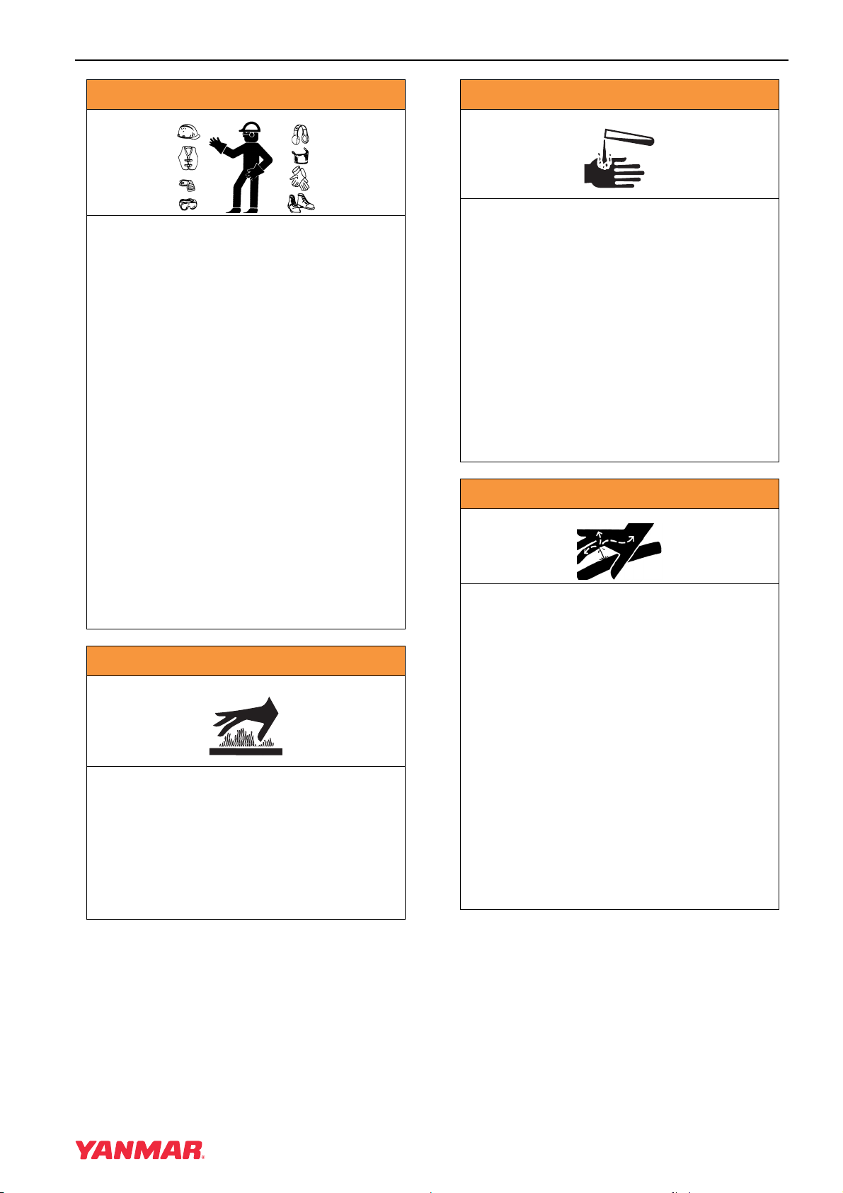
A WARNING
EXPOSURE HAZARD!
• Wear personal protective equipment
such as gloves, work shoes, eye and
hearing protection as required by the
task at hand.
• NEVER wear jewelry, unbuttoned
cuffs, ties or loose fitting clothing
when you are working near
moving / rotating parts such as the
cooling fan, flywheel or PTO shaft.
• ALWAYS tie long hair back when you
are working near moving / rotating
parts such as a cooling fan, flywheel,
or PTO shaft.
• NEVER operate the engine while
wearing a headset to listen to music or
radio because it will be difficult to hear
warning signals.
A WARNING
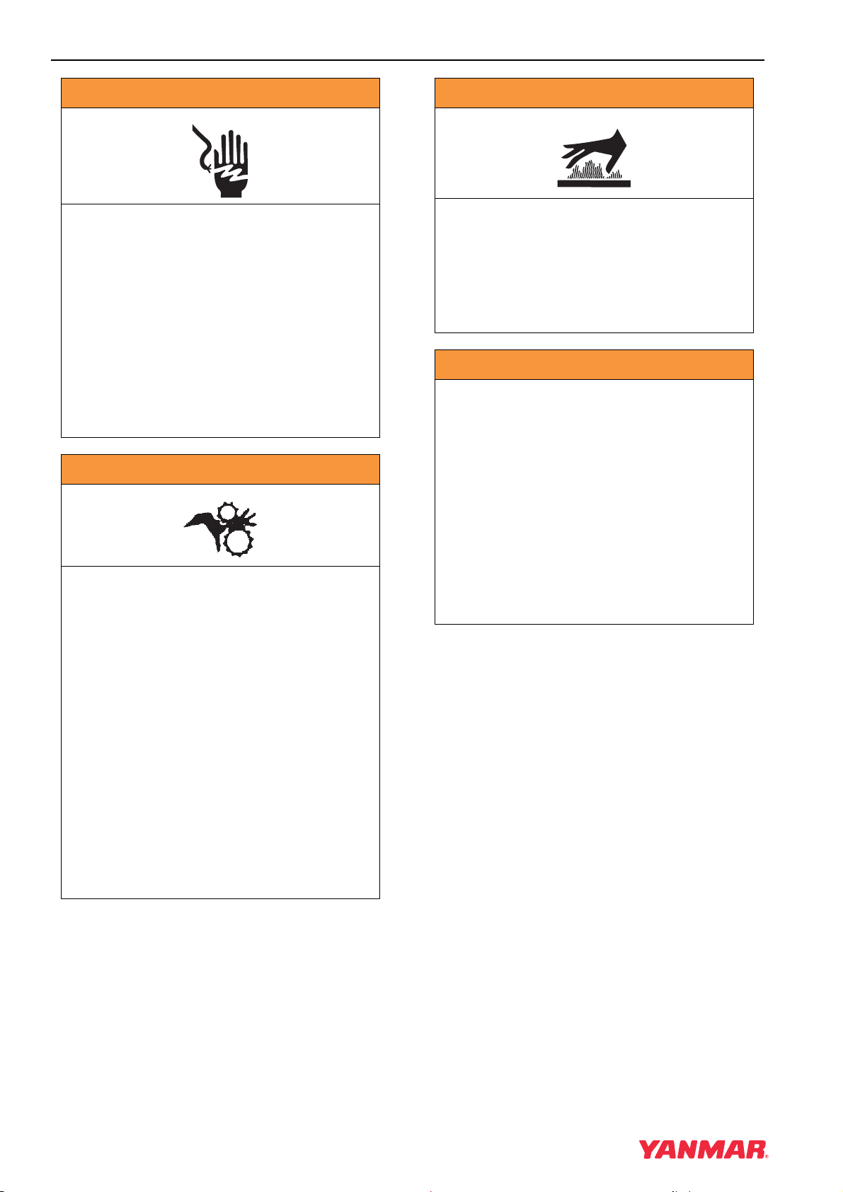
BURN HAZARD!
• Batteries contain sulfuric acid. NEVER
allow battery fluid to come in contact
with clothing, skin or eyes. Severe
burns could result. ALWAYS wear
safety goggles and protective clothing
when servicing the battery. If contact
with the skin and / or eyes should
occur, flush with a large amount of
water and obtain prompt medical
treatment.
• Failure to comply could result in death
or serious injury.
0000007en
A WARNING
• Failure to comply could result in death
or serious injury.
0000005en
A WARNING
BURN HAZARD!
• If you must drain the engine oil while it
is still hot, stay clear of the hot engine
oil to avoid being scalded. Make sure
you wear eye protection.
• Failure to comply could result in death
or serious injury.
0000011en
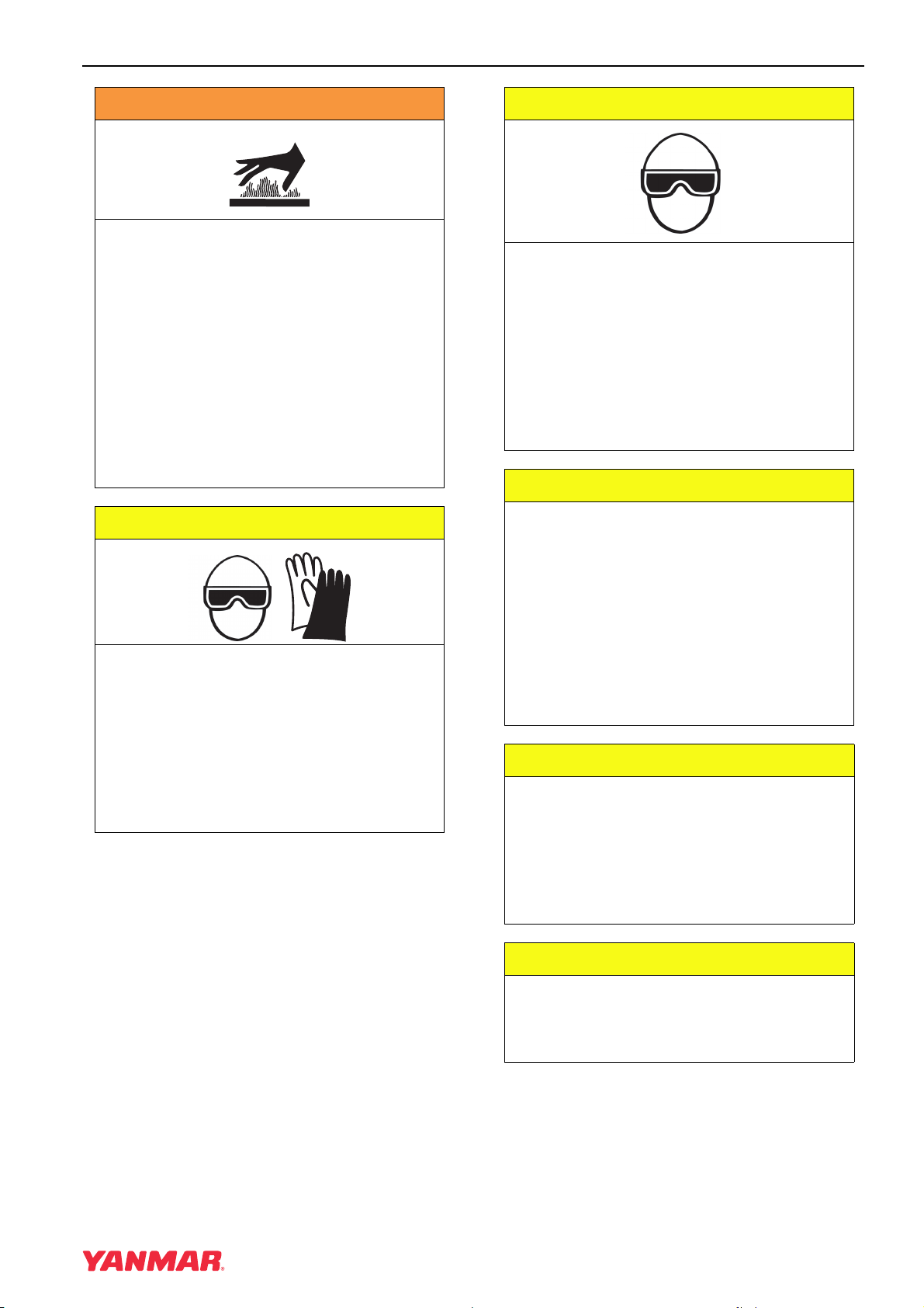
HIGH PRESSURE HAZARD!
• Avoid skin contact with high pressure
diesel fuel spray caused by a fuel
system leak such as a broken fuel
injection line. High pressure fuel can
penetrate your skin and result in
serious injury. If you are exposed to
high pressure fuel spray obtain
prompt medical treatment.
• NEVER check for a fuel leak with your
hands. ALWAYS use a piece of wood
or cardboard. Have your authorized
Yanmar industrial engine dealer or
distributor repair the damage.
• Failure to comply could result in death
or serious injury.
0000008en
TNV Operation Manual
7
Page 26
SAFETY
A WARNING
SHOCK HAZARD!
• Turn off the battery switch (if
equipped) or disconnect the negative
battery cable before servicing the
electrical system.
• Check the electrical harnesses for
cracks, abrasions, and damaged or
corroded connectors. ALWAYS keep
the connectors and terminals clean.
• Failure to comply could result in death
or serious injury.
0000009en
A WARNING
SEVER HAZARD!
• Stop the engine before you begin to
service it.
A WARNING
BURN HAZARD!
• Wait until the engine cools before you
drain the engine coolant. Hot engine
coolant may splash and burn you.
• Failure to comply could result in death
or serious injury.
0000016en
A WARNING
SUDDEN MOVEMENT HAZARD!
• Allow the engine to warm-up for at
least 5 minutes to allow the engine idle
speed to return to normal before
engaging the transmission or any PTO
attachments. Engaging the
transmission or PTO at an elevated
engine speed could result in an
unexpected movement of the
equipment.
• Failure to comply could result in death
or serious injury.
0000006en
• NEVER leave the key in the key switch
when you are servicing the engine.
Someone may accidentally start the
engine and not realize you are
servicing it. This could result in a
serious injury.
• If you must service the engine while it
is operating, remove all jewelry, tie
back long hair, and keep your hands,
other body parts and clothing away
from moving / rotating parts.
• Failure to comply could result in death
or serious injury.
0000010en
8
TNV Operation Manual
Page 27
SAFETY
A WARNING
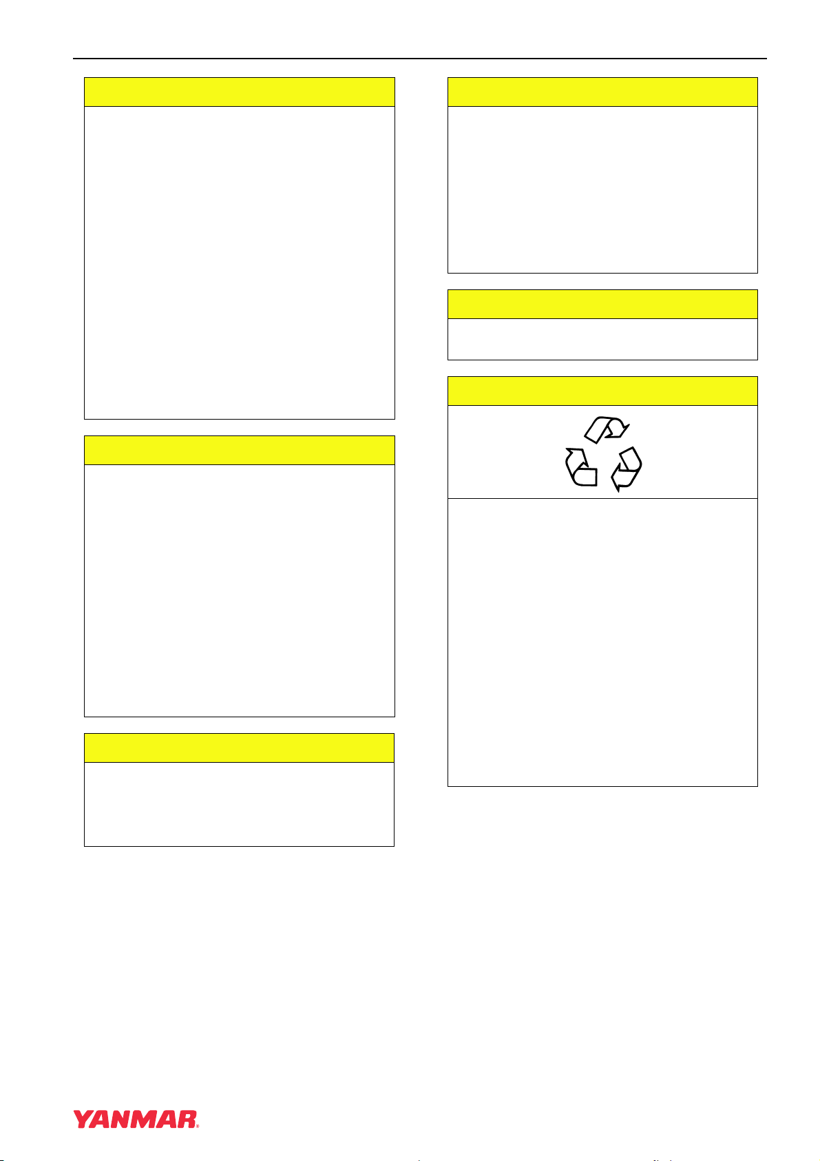
BURN HAZARD!
• Keep your hands, and other body
parts, away from hot engine surfaces
such as the muffler, exhaust pipe,
turbocharger (if equipped) and engine
block during operation and shortly
after you shut the engine down. These
surfaces are extremely hot while the
engine is operating and could
seriously burn you.
• Failure to comply could result in death
or serious injury.
0000015en
A CAUTION
A CAUTION
FLYING OBJECT HAZARD!
• ALWAYS wear eye protection when
servicing engine and when using
compressed air or high-pressure
water. Dust, flying debris, compressed
air, pressurized water or steam may
injure your eyes.
• Failure to comply may result in minor
or moderate injury.
0000003en
CAUTION
• Only use diesel fuels recommended by
Yanmar for the best engine
performance, to prevent engine
damage and to comply with EPA / ARB
warranty requirements.
COOLANT HAZARD!
• Wear eye protection and rubber gloves
when you handle Long Life or
Extended Life Engine Coolant. If
contact with the eyes or skin should
occur, wash with clean water.
• Failure to comply may result in minor
or moderate injury.
0000005en
• Only use clean diesel fuel.
• NEVER remove primary strainer from
the fuel tank filler port. If removed, dirt
and debris could get into the fuel
system causing it to clog.
0000004en
CAUTION
NEVER attempt to adjust the low or high
idle speed limit screw. This may impair
the safety and performance of the
machine and shorten its life. If
adjustment is ever required, contact
your authorized Yanmar industrial
engine dealer or distributor.
0000045en
CAUTION
If any problem is noted during the visual
check, the necessary corrective action
should be taken before you operate the
engine.
0000021en
TNV Operation Manual
9
Page 28

SAFETY
CAUTION
NEVER hold the key in the START
position for longer than 15 seconds or
the starter motor will overheat.
0000007en
CAUTION
Make sure the engine is installed on a
level surface. If a continuously running
engine is installed at an angle greater
than 30° (in any direction) or if an engine
runs for short periods of time (less than
3 minutes) at an angle greater than 35°
(in any direction) engine oil may enter
the combustion chamber causing
exessive engine speed and generate
white smoke. This may cause serious
engine damage.
0000010en
CAUTION
Observe the following environmental
operating conditions to maintain engine
performance and avoid premature
engine wear:
• Avoid operating in extremely dusty
conditions.
• Avoid operating in the presence of
chemical gases or fumes.
• Avoid operating in a corrosive
atmosphere such as salt water spray.
• NEVER install the engine in a
floodplain unless proper precautions
are taken to avoid being subject to a
flood.
• NEVER expose the engine to the rain.
0000003en
CAUTION
Observe the following environmental
operating conditions to maintain engine
performance and avoid premature
engine wear:
• NEVER run the engine if the ambient
temperature is above +113°F (+45°C)
or below +5°F (-15°C).
◆ If the ambient temperature exceeds
+113°F (+45°C) the engine may
overheat and cause the engine oil to
break down.
◆ If the ambient temperature falls
below +5°F (-15°C) rubber
components such as gaskets and
seals will harden causing premature
engine wear and damage.
◆ Contact your authorized Yanmar
industrial engine dealer or
distributor if the engine will be
operated in either temperature
extreme.
• Contact your authorized Yanmar
industrial engine dealer or distributor
if you need to operate the engine at
high altitudes. At high altitudes the
engine will lose power, run rough, and
produce exhaust gases that exceed
the design specifications.
0000065en
CAUTION
The illustrations and descriptions of
optional equipment in this manual, such
as the operator’s console, are for a
typical engine installation. Refer to the
documentation supplied by the optional
equipment manufacturer for specific
operation and maintenance instructions.
0000018en
10
CAUTION
If any indicator illuminates during
engine operation stop the engine
immediately. Determine the cause and
repair the problem before you continue
to operate the engine.
0000029en
TNV Operation Manual
Page 29
SAFETY
CAUTION
• Only use the engine oil specified.
Other engine oils may affect warranty
coverage, cause internal engine
components to seize, or shorten
engine life.
• Prevent dirt and debris from
contaminating engine oil. Carefully
clean the oil cap / dipstick and the
surrounding area before you remove
the cap.
• NEVER mix different types of engine
oil. This may adversely affect the
lubricating properties of the engine oil.
• NEVER overfill. Overfilling may result
in white exhaust smoke, engine
overspeed or internal damage.
0000005en
CAUTION
• Only use the engine coolant specified.
Other engine coolants may affect
warranty coverage, cause an internal
build up of rust and scale and / or
shorten engine life.
• Prevent dirt and debris from
contaminating engine coolant.
Carefully clean the radiator cap and
the surrounding area before you
remove the cap.
• NEVER mix different types of engine
coolants. This may adversely affect the
properties of the engine coolant.
0000006en
CAUTION
• NEVER overfill the engine with engine
oil.
CAUTION
For maximum engine life, Yanmar
recommends that when shutting the
engine down, you allow the engine to
idle, without load, for 5 minutes. This
will allow the engine components that
operate at high temperatures, such as
the turbocharger (if equipped) and
exhaust system, to cool slightly before
the engine itself is shut down.
0000008en
CAUTION
NEVER use an engine starting aid such
as ether. Engine damage will result.
0000009en
CAUTION
Be responsible to the environment.
Follow these procedures for hazardous
waste disposal. Failure to follow these
procedures may seriously harm the
environment.
• Follow the guidelines of the EPA or
other governmental agency for the
proper disposal of hazardous
materials such as engine oil, diesel
fuel and engine coolant. Consult the
local authorities or reclamation facility.
• NEVER dispose of hazardous
materials irresponsibly by dumping
them into a sewer, on the ground or
into ground water or waterways.
0000013en
• ALWAYS keep the oil level between
upper and lower lines on the dipstick.
TNV Operation Manual
0000015en
11
Page 30
SAFETY
CAUTION
New Engine Break In:
• On the initial engine start-up, allow the
engine to idle for approximately 15
minutes while you check for proper
engine oil pressure, diesel fuel leaks,
engine oil leaks, coolant leaks, and for
proper operation of the indicators
and / or gauges.
• During the first hour of operation, vary
the engine speed and load on the
engine. Short periods of maximum
engine speed and load are desirable.
Avoid prolonged operation at
minimum or maximum engine speeds
and loads for the next 4 to 5 hours.
• During the break-in period, carefully
observe the engine oil pressure and
engine temperature.
• During the break-in period, check the
engine oil and coolant levels
frequently.
0000011en
CAUTION
NEVER engage the starter motor while
the engine is running. This may damage
the starter motor pinion and / or ring
gear.
0000012en
CAUTION
• NEVER attempt to modify the engine’s
design or safety features such as
defeating the engine speed limit
control or the fuel injection quantity
control.
• Failure to comply may impair the
engine’s safety and performance
characteristics and shorten the
engine’s life. Any alterations to this
engine may affect the warranty
coverage of your engine. See Yanmar
Limited Warranty on page v.
0000044enTNVIDI-DIOM
CAUTION
Protect the air cleaner, turbocharger (if
equipped) and electric components
from damage when you use steam or
use high-pressure water to clean the
engine.
0000014en
CAUTION
NEVER use high pressure water or
compressed air at greater than 28 psi or
a wire brush to clean the radiator fins.
Radiator fins damage easily.
0000016en
CAUTION
NEVER attempt to adjust the low or high
idle speed limit screw. This may impair
the safety and performance of the
machine and shorten its life. If the idle
speed limit screws require adjustment,
see your authorized Yanmar industrial
engine dealer or distributor.
0000017en
CAUTION
The tightening torque in the Standard
Torque Chart (page 72) should be
applied only to the bolts with a “7” head.
(JIS strength classification: 7T)
• Apply 60% torque to
bolts that are not listed.
• Apply 80% torque when
tightened to aluminum alloy.
0000023enTNVIDI-DIOM
CAUTION
If any indicator fails to illuminate when
the key switch is in the ON position, see
your authorized Yanmar industrial
engine dealer or distributor for service
before operating the engine.
0000028en
12
TNV Operation Manual
Page 31

SAFETY
CAUTION
Establish a periodic maintenance plan
according to the engine application and
make sure you perform the required
periodic maintenance at intervals
indicated. Failure to follow these
guidelines will impair the engine’s safety
and performance characteristics,
shorten the engine’s life and may affect
the warranty coverage on your engine.
See Yanmar Limited Warranty on page v.
Consult your authorized Yanmar
industrial engine dealer or distributor for
assistance when checking items marked
with a
z.
0000024enTNVIDI-DIOM
CAUTION
If no water drips when the fuel
filter / water separator drain cock is
opened, loosen the air vent screw on the
top of the fuel filter / water separator by
using a screwdriver to turn it
counterclockwise 2-3 turns.
CAUTION
Make it a habit to perform daily checks.
See Daily Checks on page 44.
Periodic maintenance prevents
unexpected downtime, reduces the
number of accidents due to poor
machine performance and helps extend
the life of the engine.
0000060enTNVIDI-DIOM
This may occur if the fuel filter / water
separator is positioned higher than the
fuel level in the fuel tank. After draining
the fuel filter / water separator, be sure
to tighten the air vent screw.
0000025en
CAUTION
• When the engine is operated in dusty
conditions, clean the air cleaner
element more frequently.
• NEVER operate the engine with the air
cleaner or element(s) removed. This
may cause foreign material to enter the
engine and damage it.
0000026en
CAUTION
The maximum air intake restriction shall
be 0.90 psi (6.23 kPa; 635 mm Aq) or
less. Clean or replace the air cleaner
element if the air intake restriction
exceeds the above mentioned value.
0000046en
TNV Operation Manual
13
Page 32

SAFETY
14
TNV Operation Manual
Page 33

PRODUCT
OVERVIEW
TNV Operation Manual
YANMAR TNV ENGINE FEATURES AND APPLICATIONS
Yanmar’s series of TNV engines are
environmentally friendly and are designed to:
• Lower the amount of exhaust gas emissions.
• Reduce engine noise and vibration.
• Be easy to start thanks to the specially
designed fuel injection pump and combustion
system.
• Be economical to run because diesel fuel and
engine oil consumption are reduced.
• Be easy to operate due to the minimum amount
of required maintenance and its compact
design.
• Be durable and reliable due in part to the newly
designed fuel injection valve and fuel injection
pump.
Yanmar TNV engines are designed to supply
power to a wide variety of driven machines
including:
• Construction
•Agriculture
• Power Generation
We are sure that you will agree these features
provide excellent value in an industrial diesel
engine.
These engines are designed to deliver power to
driven machines by means of a “direct coupled
drive” or “belt drive”. In direct coupled drive
engine applications, the engine’s flywheel
housing or end plate is coupled directly to the
driven machine. In belt drive engine applications,
a belt drive is used to power the driven machine.
If you have applications that require a belt drive
and / or front power take-off (PTO), please
contact your authorized Yanmar industrial engine
dealer or distributor.
The engine is designed for a wide range of
applications. Options (such as fuel tank, control
panel, indicators, gauges and alarms) are
available to customize the application.
Since designing the application and installing the
engine require special knowledge and skill,
always consult your authorized Yanmar industrial
engine dealer or distributor for these services.
They will help you:
• Select optional equipment. Optional equipment
should be selected to match the work
conditions and environment.
• Maximize engine performance with a minimum
amount of downtime and safety related
incidents by carefully matching the
characteristics of the engine with the driven
machine.
• Plan for safe fuel piping, exhaust piping,
electrical wiring, ventilation and accurate
engine installation.
• Design your applications so they meet
requirements of the local authorities.
TNV Operation Manual
15
Page 34

PRODUCT OVERVIEW
COMPONENT IDENTIFICATION
2TNV70, 3TNV70, 3TNV76
Figure 1 shows where major indirect injection engine components are located.
(18)
(17)
(16)
(15)
(14)
(19)
(13)
(12)
(11)
(1)
(10)
(9)
(8)
(2)
(7)
(6)
(3)
(5)
(4)
Figure 1
(25)
(24)
(23)
(20)
(21)
(22)
0000583A
1. Lifting Eye (Flywheel End)
2. Engine Coolant Pump
3. Lifting Eye (Engine Cooling Fan End)
4. Engine Cooling Fan
5. V-Belt
6. Crankshaft V-Pulley
7. Side Filler Port (Engine Oil)
8. Drain Plug (Engine Oil)*
9. Fuel Inlet
10. Mechanical Fuel Pump
11. Fuel Priming Lever
12. Dipstick (Engine Oil)
14. Governor Lever
15. Fuel Injection Pump
16. Intake Manifold
17. Air Intake Port (From Air Cleaner)
18. Fuel Filter
19. Fuel Return To Fuel Tank
20. Top Filler Port (Engine Oil)
21. Rocker Arm Cover
22. Flywheel
23. Starter Motor
24. Exhaust Manifold
25. Alternator
13. Engine Oil Filter
*Engine oil drain plug location may vary based on oil pan options.
16
TNV Operation Manual
Page 35

PRODUCT OVERVIEW
3TNV82A, 3TNV84, 3TNV84T, 3TNV88, 4TNV84, 4TNV84T, 4TNV88, 4TNV94L, 4TNV98,
4TNV98T, 4TNV106, 4TNV106T
Figure 2 shows where major direct injection engine components are located.
(1)
(18)
(17)
(16)
(15)
(14)
(13)
(2)
(3)
(4)
(10)(11)(12)
(7)(8)(9)
1. Lifting Eye (Flywheel End)
2. Turbocharger*
3. Lifting Eye (Engine Cooling Fan End)
4. Engine Coolant Pump
5. Engine Cooling Fan
6. Crankshaft V-Pulley
7. V-Belt
8. Side Filler Port (Engine Oil)
9. Drain Plug (Engine Oil)**
10. Fuel Injection Pump
11. Engine Oil Cooler***
12. Engine Oil Filter
13. Dipstick (Engine Oil)
(20)
(23)
(6)
(19)
(5)
(25)
(24)
Figure 2
14. Governor Lever
15. Intake Manifold
16. Fuel Filter
17. Fuel Inlet
18. Fuel Return To Fuel Tank
19. Top Filler Port (Engine Oil)
20. Rocker Arm Cover
21. Air Intake Port (From Air Cleaner)
22. Flywheel
23. Starter Motor
24. Exhaust Manifold
25. Alternator
(21)
(22)
0000015B
* Only applies to 3TNV84T, 4TNV84T, 4TNV98T, 4TNV106T
** Engine oil drain plug location may vary based on oil pan options.
*** Not standard on all direct injection models
TNV Operation Manual
17
Page 36

PRODUCT OVERVIEW
LOCATION OF LABELS
Figure 3 shows the location of regulatory and safety labels on Yanmar TNV series indirect
injection model engines.
(2)
(1)
The typical location of the emission control
information label is shown (Figure 3, (1)).
Typical location of the engine nameplate is shown
(Figure 3, (2)).
0000585A
Figure 3
Figure 4 shows the location of regulatory and safety labels on Yanmar TNV series direct
injection model engines.
(3)
(1)
(4)
(2)
(4)
0000019A
Figure 4
The typical location of the emission control information label is shown for 4TNV84, 4TNV84T and
4TNV88 engines (Figure 4, (1)).
The typical location of the emission control information label is affixed to the exhaust side of the rocker
arm cover for 3TNV82A, 3TNV84, 3TNV84T and 3TNV88 engines (Figure 4, (2)).
The typical location of the emission control information label is affixed to the exhaust side of the rocker
arm cover for 4TNV94L, 4TNV98, 4TNV98T, 4TNV106 and 4TNV106T engines (Figure 4, (3)).
Typical location of the engine nameplate is shown for various Yanmar TNV engines (Figure 4, (4)).
18
TNV Operation Manual
Page 37

PRODUCT OVERVIEW
Engine Nameplate (Typical)
MODEL
MAX. OUTPUT
rpm
DISPLACEMENT
ENGINE NO.
YANMAR DIESEL ENGINE
MADE IN JAPAN
0000287
EPA / ARB EMISSION
CONTROL REGULATIONS -
EMISSION CONTROL LABELS
Since emission control regulations are being
issued on a global basis, it is necessary to
identify which regulations a particular engine
complies with. We have listed several different
types of labels you might find on your engine.
EPA / ARB Labels
" "
(EPA) Less Than 50 HP SAE (37kW)
USA ONLY
Yanmar TNV engines meet Environmental
Protection Agency (EPA) (U. S. Federal) emission
control standards as well as the California Air
Resources Board (ARB, California) regulations.
Only engines that conform to ARB regulations
can be sold in the State of California.
Refer to the specific EPA / ARB installation
(page 72) and maintenance (page 72) in the
Periodic Maintenance section of this manual.
Also refer to the Yanmar Co., Ltd. Limited
Emission Control System Warranty - USA
Only on page viii.
"
US-2D " FUEL
(EPA) Greater Than or Equal To 50 HP SAE (37kW)
(EPA & ARB)
TNV Operation Manual
19
Page 38

PRODUCT OVERVIEW
THE 97/68/EC DIRECTIVE CERTIFIED ENGINES
The engines described in this manual have been
certified by the 97/68/EC Directive.
To identify the engines that meet this certification,
the 97/68/EC emission control label is affixed on
the engines.
ENGINE FAMILY
The EPA / ARB labels and the 97/68/EC label all
have an Engine Family field. The following is an
explanation of the Engine Family designation:
5YDXL1.33M 3 N
Method of air aspiration
Number of cylinders
Engine speed specifications
Displacement (liter)
Non-road / Off-road engine
97/68/EC DIRECTIVE
(97/68/EC)
Yanmar Diesel
*2005 Model Year
5*: 2005
6 : 2006
7 : 2007
20
TNV Operation Manual
Page 39

PRODUCT OVERVIEW
FUNCTION OF MAJOR ENGINE COMPONENTS
Components Functions
Air Cleaner The air cleaner prevents airborne contaminants from entering the
engine. Since the air cleaner is application specific, it must be
carefully selected by an application engineer. It is not part of the
basic engine package as shipped from the Yanmar factory. Periodic
replacement of the air cleaner filter element is necessary. See the
Periodic Maintenance Schedule on page 73 for the replacement
frequency.
Alternator The alternator is driven by a V-belt which is powered by the
crankshaft V-pulley. The alternator supplies electricity to the engine
systems and charges the battery while the engine is running.
Dipstick (Engine Oil) The engine oil dipstick is used to determine the amount of engine
oil in the crankcase.
Electric Fuel Pump The electric fuel pump makes sure there is a constant supply of
diesel fuel to the fuel injection pump. The electric fuel pump is
electro-magnetic and runs on 12 VDC. An electric fuel pump may
be installed as an option or as standard equipment. Standard
equipment may vary based on engine model and specification. If an
electric fuel pump is installed, turn the key switch to the ON position
for 10 to 15 seconds to prime the fuel system.
Engine Oil Filter The engine oil filter removes contaminants and sediments from the
engine oil. Periodic replacement of the engine oil filter is necessary.
See the Periodic Maintenance Schedule on page 73 for the
replacement frequency.
Engine Oil Cooler
(If Equipped)
The engine oil cooler helps to keep the engine oil cool. Engine
coolant from the cooling system is circulated through an adapter at
the base of the engine oil filter assembly and then returned to the
cylinder block.
Fuel Filter The fuel filter removes contaminants and sediments from the diesel
fuel. Periodic replacement of the fuel filter is necessary. See the
Periodic Maintenance Schedule on page 73 for the replacement
frequency. Please note that the word “diesel” is implied
throughout this manual when the word “fuel” is used.
Fuel Filter / Water Separator The fuel filter / water separator removes contaminants, sediments
and water from diesel fuel going to the fuel filter. This is a required
component of the fuel system. This is standard equipment with
every engine. The separator is installed between the fuel tank and
the fuel pump. Periodically drain the water from the fuel filter / water
separator using the drain cock at the bottom of the separator.
TNV Operation Manual
21
Page 40

PRODUCT OVERVIEW
Components Functions
Fuel Priming Lever If the unit has a mechanical fuel pump, a fuel priming lever on the
mechanical fuel pump primes the fuel system. The fuel system
needs to be primed before you start the engine for the first time, if
you run out of fuel, or if fuel system service is performed. To prime
the fuel system, operate the fuel priming lever until the cup in the
fuel filter is full of fuel.
Fuel Tank The fuel tank is a reservoir that holds diesel fuel. When fuel leaves
the fuel tank it goes to the fuel filter / water separator. Next, fuel is
pumped to the fuel filter by the electric or mechanical fuel pump.
Next the fuel goes to the fuel injection pump. Since fuel is used to
keep the fuel injection pump cool and lubricated, more fuel than
necessary enters the injection pump. When the injection pump
pressure reaches a preset value, a relief valve allows excess fuel to
be returned back to the fuel tank. The fuel tank is a required engine
component.
Mechanical Fuel Pump The mechanical fuel pump is a diaphragm type of pump and is
installed on the fuel injection pump body. The mechanical fuel
pump is driven by a cam on the camshaft of the fuel injection pump.
An electric fuel pump is available as an option. The mechanical fuel
pump is not installed on the fuel injection pump if the electric fuel
pump option is installed.
Side and Top Filler Port (Engine
Oil)
Starter Motor The starter motor is powered by the battery. When you turn the key
You can fill the crankcase with engine oil from either the side or
top filler port depending upon which one is most convenient.
switch in the operator’s console to the START position, the starter
motor engages with the ring gear installed on the flywheel and
starts the flywheel in motion.
Turbocharger
(Only applies to 3TNV84T,
4TNV84T, 4TNV98T,
4TNV106T)
The turbocharger pressurizes the air coming into the engine. It is
driven by a turbine that is energized by exhaust gases.
22
TNV Operation Manual
Page 41

PRODUCT OVERVIEW
FUNCTION OF COOLING SYSTEM COMPONENTS
Components Functions
The TNV engine is liquid-cooled by means of a cooling system. The
cooling system consists of a radiator, radiator cap, engine cooling
fan, engine coolant pump, thermostat, and reserve tank. Note that
Cooling System
• Engine Cooling Fan The engine cooling fan is driven by a V-belt which is powered by the
• Engine Coolant Pump The engine coolant pump circulates the engine coolant through the
• Radiator The radiator acts as a heat exchanger. As the engine coolant
• Radiator Cap The radiator cap controls the cooling system pressure. The cooling
all cooling system components are required for proper engine
operation. Since some of the components are application
specific, they must be carefully selected by an application
engineer. The application specific items are not part of the
basic engine package as shipped from the Yanmar factory.
crankshaft V-pulley. The purpose of the engine cooling fan is to
circulate air through the radiator.
cylinder block and cylinder head and returns the engine coolant to
the radiator.
circulates through the cylinder block it absorbs heat. The heat in the
engine coolant is dissipated in the radiator. As the engine cooling
fan circulates air through the radiator, the heat is transferred to the
air.
system is pressurized to raise the boiling point of the engine
coolant. As the engine coolant temperature rises, the system
pressure and the coolant volume increases. When the pressure
reaches a preset value, the release valve in the radiator cap opens
and the excess engine coolant flows into the reserve tank. As the
engine coolant temperature is reduced, the system pressure and
volume is reduced and the vacuum valve in the radiator cap opens
allowing engine coolant to flow from the reserve tank back into the
radiator.
• Reserve Tank The reserve tank contains the overflow of engine coolant from the
radiator. If you need to add engine coolant to the system, add it to
the reserve tank; not the radiator.
• Thermostat A thermostat is placed in the cooling system to prevent engine
coolant from circulating into the radiator until the engine coolant
temperature reaches a preset temperature. When the engine is
cold, no engine coolant flows through the radiator. Once the engine
reaches its operating temperature the thermostat opens and allows
engine coolant to flow through the radiator. By letting the engine
warm up as quickly as possible, the thermostat reduces engine
wear, deposits and emissions.
TNV Operation Manual
23
Page 42

PRODUCT OVERVIEW
GAUGES AND INDICATORS
The operator’s console provides you with the
means to start and stop the unit and a series of
gauges and indicators that inform you about the
current status of the engine. This is a required
engine component. Since the operator’s console
is application specific, it must be carefully
selected by an application engineer. It is not part
of the basic engine package as shipped from the
Yanmar factory.
CAUTION
The illustrations and descriptions of
optional equipment in this manual, such
as the operator’s console, are for a
typical engine installation. Refer to the
documentation supplied by the optional
equipment manufacturer for specific
operation and maintenance instructions.
0000018en
Gauges
The following gauges are located on a typical
operator’s console. Some operator’s consoles
may not have the gauges described here or may
have different gauges.
(1) (2)
(3)
20
RPM
10
(3)
30
x100
0
40
VDO
PSI
40
20
60
0
80
2
3
1
4
0
5
bar
VDO
AUX
180
100
80
0
MC-704HP-G4
F
220
250
100
120
C
0000024A
(1)
(2)
(4)
Figure 6
Tachometer - The tachometer display
(Figure 5, (1)) or (Figure 6, (1)) shows the
engine speed in Revolutions Per Minute (rpm).
Engine Coolant Temperature - The engine
coolant temperature display (Figure 5, (2)) or
(Figure 6, (2)) shows the temperature of the
engine coolant.
Engine Oil Pressure - The engine oil pressure
display (Figure 5, (3)) or (Figure 6, (3)) shows
the pressure of the engine oil.
(4)
Hour Meter - The hour meter display
(Figure 5, (4)) or (Figure 6, (4)) shows the total
number of hours the engine has run. This is
useful for planning the Periodic Maintenance
Procedures operations on page 75.
0000023A
Figure 5
24
TNV Operation Manual
Page 43

PRODUCT OVERVIEW
Indicators
The following indicators are located on a typical
operator’s console.
20
RPM
10
30
x100
0
40
VDO
PSI
40
20
60
0
80
2
3
1
4
0
5
bar
VDO
AUX
180
100
80
0
MC-704HP-G4
F
220
250
100
120
C
(1)
(2)
(3)
(4)
(5)
0000024B
Pre-Heat - (Figure 7, (1)) - The pre-heat function
is automatically activated when the key switch is
turned to the ON position. The indicator flashes
for several seconds and when it goes out you can
turn the key switch to START.
Heat - (Figure 8, (1)) - Note that on this type of
panel you must turn the key to the HEAT position
(Figure 8, (5)) to activate the inlet air
heater(direct injection models) or glow plugs
(indirect injection models). The indicator will flash
for several seconds when you turn the key to
HEAT and when it goes out, you can turn the key
switch to START.
Battery - (Figure 7, (2)) or (Figure 8, (2)) - This
indicator will come on if there is a problem in the
charging system. This indicator does not indicate
whether the battery is discharged. See
Troubleshooting Chart on page 99.
Engine Oil Pressure - (Figure 7, (3)) or
(Figure 8, (3)) - This indicator will come on if the
engine oil pressure is below or exceeds normal
limits. See Troubleshooting Chart on page 99.
(5)
(1)
Figure 7
(2)
Figure 8
(3)
0000025B
Engine Coolant Temperature - (Figure 7, (4))
or (Figure 8, (4)) - This indicator will come on if
the engine coolant temperature exceeds normal
limits. See Troubleshooting Chart on page 99.
Auxiliary - (Figure 7, (5)) - Used for special
applications.
(4)
TNV Operation Manual
25
Page 44

PRODUCT OVERVIEW
CONTROLS
Key Switch
The key switch for the operator’s console
illustrated in Figure 9 has three positions - OFF,
ON, and START.
20
RPM
10
30
x100
0
40
VDO
PSI
40
20
60
0
80
2
3
1
4
0
5
bar
VDO
180
100
80
0
MC-704HP-G4
F
220
250
100
120
C
(1)
ON (Figure 9, (2)) - This is the position the key
will be in when the engine is running. When the
engine is not running, use this position to
energize the gauges, indicators, electric fuel
pump and auxiliary devices.
CAUTION
NEVER hold the key in the START
position for longer than 15 seconds or
the starter motor will overheat.
0000007en
START (Figure 9, 3)) - Turn the key to this
position to start the engine. As soon as the
engine starts, release the key and it will
automatically return to the ON position. Some key
switches may be equipped with a feature that
prevents you from turning the key to the START
position while the engine is running. In these
configurations, you cannot turn the key to the
START position without first returning the key to
the OFF position.
AUX
(2)
(3)
0000011A
Figure 9
CAUTION
For maximum engine life, Yanmar
recommends that when shutting the
engine down, you allow the engine to
idle, without load, for 5 minutes. This
will allow the engine components that
operate at high temperatures, such as
the turbocharger (if equipped) and
exhaust system, to cool slightly before
the engine itself is shut down.
OFF (key straight up and down) (Figure 9, (1)) -
When you turn the key to this position the engine
shuts down. Electric current to the gauges and
indicators is shut off. You can insert and remove
the key in this position.
0000008en
The key switch for the operator’s console
illustrated in Figure 10 has four positions - OFF,
ON, START, and HEAT.
(1)
(2)
(3)
(4)
0000021A
Figure 10
26
TNV Operation Manual
Page 45

PRODUCT OVERVIEW
CAUTION
For maximum engine life, Yanmar
recommends that when shutting the
engine down, you allow the engine to
idle, without load, for 5 minutes. This
will allow the engine components that
operate at high temperatures, such as
the turbocharger (if equipped) and
exhaust system, to cool slightly before
the engine itself is shut down.
OFF (Figure 10, (1)) - When you turn the key to
this position the engine shuts down. Electric
current to the gauges and indicators is shut off.
You can insert and remove the key in this
position.
ON (Figure 10, (2)) - This is the position the key
will be in when the engine is running. When the
engine is not running, use this position to
energize the gauges, indicators, electric fuel
pump and auxiliary devices.
0000008en
Glow Plugs
Glow plugs are installed in the cylinder head swirl
chambers to help make the engine easy to start
in cold temperatures. During the engine starting
sequence, the glow plugs are activated for
several seconds. After the preheat / heat indicator
goes out, the engine can be started.
Inlet Air Heater
(1)
CAUTION
NEVER hold the key in the START
position for longer than 15 seconds or
the starter motor will overheat.
0000007en
START (Figure 10, (3)) - Turn the key to this
position to start the engine. As soon as the
engine starts, release the key and it will
automatically return to the ON position. Some key
switches may be equipped with a feature that
prevents you from turning the key to the START
position while the engine is running. You cannot
turn the key to the START position without first
returning the key to the OFF position.
HEAT (Figure 10, (4)) - You must turn the key to
the HEAT position to activate the inlet air heater.
The indicator will flash for several seconds when
you turn the key to HEAT. You can turn the key to
START when the indicator goes out.
0000027A
Figure 11
The inlet air heater (Figure 11, (1)) is located on
the intake manifold. Heated inlet air helps the
engine to start easier in cold weather. During the
engine starting sequence the inlet air heater is
activated for several seconds. After the pre-heat /
heat indicator goes out, the engine can be
started. The inlet air heater is standard
equipment with every engine.
TNV Operation Manual
27
Page 46

PRODUCT OVERVIEW
Governor Lever
(2)
(1)
(3)
(2)
0000648A
(3)
(1)
Engine Stop Solenoid
(1)
0000028A
Figure 13
When the key is turned to the ON position, the
engine stop solenoid (Figure 13, (1)) is
energized and allows the fuel injection pump to
deliver fuel to the engine, allowing the engine to
be started. When the key is turned to the OFF
position, the engine stop solenoid is de-energized
and shuts off the fuel supply from the fuel
injection pump to the engine, causing the engine
to stop.
0000026A
Figure 12
CAUTION
NEVER attempt to adjust the low or high
idle speed limit screw. This may impair
the safety and performance of the
machine and shorten its life. If
adjustment is ever required, contact
your authorized Yanmar industrial
engine dealer or distributor.
The governor lever (Figure 12, (1)) controls the
engine speed. The lever is linked to the engine
speed control device in the driven machine.
The high idle speed limit screw (Figure 12, (2))
restricts the maximum engine speed when the
engine is operated without a load.
The low idle speed limit screw (Figure 12, (3))
sets engine speed while it is idling.
0000045en
28
TNV Operation Manual
Page 47

BEFORE YOU
OPERATE
TNV Operation Manual
This section of the Operation Manual describes
the diesel fuel, engine oil, and engine coolant
specifications and how to replenish them. It also
describes the daily engine checkout.
A DANGER
SCALD HAZARD!
• NEVER remove the radiator cap if the
engine is hot. Steam and hot engine
coolant will spurt out and seriously
burn you. Allow the engine to cool
down before you attempt to remove
the radiator cap.
• Securely tighten the radiator cap after
you check the radiator. Steam can
spurt out during engine operation if
the cap is loose.
• ALWAYS check the level of engine
coolant by observing the reserve tank.
• Failure to comply will result in death or
serious injury.
0000002en
ADANGER
FIRE AND EXPLOSION HAZARD!
• Diesel fuel is extremely flammable and
explosive under certain conditions.
• When you prime the fuel system,
operate the fuel priming lever of the
mechanical fuel pump several times
until the fuel filter cup is filled with
fuel.
• NEVER open the air vent valve while
the fuel system is being primed. The
fuel filter has an internal air bleed port.
• Failure to comply will result in death or
serious injury.
0000001en0000016en
TNV Operation Manual
29
Page 48

BEFORE YOU OPERATE
A DANGER
FIRE AND EXPLOSION HAZARD!
• Diesel fuel is extremely flammable and
explosive under certain conditions.
• If the unit has an electric fuel pump,
when you prime the fuel system, turn
the key switch to the ON position for
10 to 15 seconds to allow the electric
fuel pump to prime the system.
• If the unit has a mechanical fuel pump,
when you prime the fuel system,
operate the fuel priming lever of the
mechanical fuel pump several times
until the fuel filter cup is filled with
fuel.
• NEVER open the air vent valve while
the fuel system is being primed. The
fuel filter has an internal air bleed port.
• Failure to comply will result in death or
serious injury.
0000013en
A DANGER
FIRE AND EXPLOSION HAZARD!
• Diesel fuel is extremely flammable and
explosive under certain conditions.
• Only fill fuel tank with diesel fuel.
Filling fuel tank with gasoline may
result in a fire.
• NEVER refuel with engine running.
• Wipe up all spills immediately.
• Keep sparks, open flames or any other
form of ignition (match, cigarette,
static electric source) away when
fueling / refueling.
• NEVER overfill the fuel tank.
• Fill fuel tank and store fuel in a wellventilated area only.
• Failure to comply will result in death or
serious injury.
0000005en
30
TNV Operation Manual
Page 49

BEFORE YOU OPERATE
A DANGER
FIRE AND EXPLOSION HAZARD!
• Diesel fuel is extremely flammable and
explosive under certain conditions.
• Be sure to place the diesel fuel
container on the ground when
transferring diesel fuel from the pump
to the container. Hold the hose nozzle
firmly against the side of the container
while filling it. This prevents static
electricity build-up which could cause
sparks and ignite fuel vapors.
• NEVER place diesel fuel or other
flammable material such as oil, hay or
dried grass close to the engine during
engine operation or shortly after shut
down.
A DANGER
FIRE AND EXPLOSION HAZARD!
• Diesel fuel is extremely flammable and
explosive under certain conditions.
• Before you operate the engine, check
for fuel leaks. Replace rubberized fuel
hoses every two years or every 2000
hours of engine operation, whichever
comes first, even if the engine has
been out of service. Rubberized fuel
lines tend to dry out and become
brittle after two years or 2000 hours of
engine operation, whichever comes
first.
• Failure to comply will result in death or
serious injury.
0000015en
• Failure to comply will result in death or
serious injury.
0000014en
A WARNING
HIGH PRESSURE HAZARD!
• Avoid skin contact with high pressure
diesel fuel spray caused by a fuel
system leak such as a broken fuel
injection line. High pressure fuel can
penetrate your skin and result in
serious injury. If you are exposed to
high pressure fuel spray obtain
prompt medical treatment.
• NEVER check for a fuel leak with your
hands. ALWAYS use a piece of wood
or cardboard. Have your authorized
Yanmar industrial engine dealer or
distributor repair the damage.
• Failure to comply could result in death
or serious injury.
0000008en
TNV Operation Manual
31
Page 50

BEFORE YOU OPERATE
A WARNING
BURN HAZARD!
• Wait until the engine cools before you
drain the engine coolant. Hot engine
coolant may splash and burn you.
• Failure to comply could result in death
or serious injury.
0000016en
A CAUTION
COOLANT HAZARD!
• Wear eye protection and rubber gloves
when you handle Long Life or
Extended Life Engine Coolant. If
contact with the eyes or skin should
occur, wash with clean water.
• Failure to comply may result in minor
or moderate injury.
0000005en
CAUTION
• Only use the engine oil specified.
Other engine oils may affect warranty
coverage, cause internal engine
components to seize, or shorten
engine life.
• Prevent dirt and debris from
contaminating engine oil. Carefully
clean the oil cap / dipstick and the
surrounding area before you remove
the cap.
• NEVER mix different types of engine
oil. This may adversely affect the
lubricating properties of the engine oil.
• NEVER overfill. Overfilling may result
in white exhaust smoke, engine
overspeed or internal damage.
0000005en
CAUTION
• Only use the engine coolant specified.
Other engine coolants may affect
warranty coverage, cause an internal
build up of rust and scale and / or
shorten engine life.
• Prevent dirt and debris from
contaminating engine coolant.
Carefully clean the radiator cap and
the surrounding area before you
remove the cap.
CAUTION
• Only use diesel fuels recommended by
Yanmar for the best engine
performance, to prevent engine
damage and to comply with EPA / ARB
warranty requirements.
• Only use clean diesel fuel.
• NEVER remove primary strainer from
the fuel tank filler port. If removed, dirt
and debris could get into the fuel
system causing it to clog.
0000004en
• NEVER mix different types of engine
coolants. This may adversely affect the
properties of the engine coolant.
0000006en
CAUTION
If any problem is noted during the visual
check, the necessary corrective action
should be taken before you operate the
engine.
0000021en
32
TNV Operation Manual
Page 51

BEFORE YOU OPERATE
DIESEL FUEL
Diesel Fuel Specifications
Diesel fuel should comply with the following
specifications. The table lists several worldwide
specifications for diesel fuels.
Diesel Fuel Specification Location
No. 2-D, No. 1-D, ASTM D975-94 USA
EN590:96 European Union
ISO 8217 DMX International
BS 2869-A1 or A2 United Kingdom
JIS K2204 Grade No.2 Japan
KSM-2610 Korea
GB252 China
Additional Technical Fuel Requirements
• The fuel cetane number should be equal to 45
or higher.
• The sulfur content must not exceed 0.5% by
volume. Less than 0.05% is preferred.
• Bio-Diesel fuels. See Bio-Diesel Fuels on
page 33.
• NEVER mix kerosene, used engine oil, or
residual fuels with the diesel fuel.
• Water and sediment in the fuel should not
exceed 0.05% by volume.
• Keep the fuel tank and fuel-handling equipment
clean at all times.
• Poor quality fuel can reduce engine
performance and / or cause engine damage.
• Fuel additives are not recommended. Some
fuel additives may cause poor engine
performance. Consult your Yanmar
representative for more information.
• Ash content not to exceed 0.01% by volume.
• Carbon residue content not to exceed 0.35% by
volume. Less than 0.1% is preferred.
• Total aromatics content should not exceed 35%
by volume. Less than 30% is preferred.
• PAH (polycyclic aromatic hydrocarbons) content
should be below 10% by volume.
• Metal content of Na, Mg, Si, and Al should be
equal to or lower than 1 mass ppm. (Test
analysis method JPI-5S-44-95)
• Lubricity: Wear mark of WS1.4 should be Max.
0.018 in (460
µm) at HFRR test.
Bio-Diesel Fuels
In Europe and in the United States, as well as
some other countries, non-mineral oil based fuel
resources such as RME (Rapeseed Methyl Ester)
and SOME (Soybean Methyl Ester), collectively
known as FAME (Fatty Acid Methyl Esters), are
being used as extenders for mineral oil derived
diesel fuels.
Yanmar approves the use of bio-diesel fuels that
do not exceed a blend of 5% (by volume) of
FAME with 95% (by volume) of approved mineral
oil derived diesel fuel. Such bio-diesel fuels are
known in the marketplace as B5 diesel fuels.
These B5 diesel fuels must meet certain
requirements.
1. The bio-fuels must meet the minimum
specifications for the country in which they
are used.
• In Europe, bio-diesel fuels must comply with
the European Standard EN14214.
• In the United States, bio-diesel fuels must
comply with the American Standard ASTM
D-6751.
2. Bio-fuels should be purchased only from
recognized and authorized diesel fuel
suppliers.
Precautions and concerns regarding the use
of bio-fuels:
1. Free methanol in FAME may result in
corrosion of aluminum and zinc FIE
components.
2. Free water in FAME may result in plugging of
fuel filters and increased bacterial growth.
TNV Operation Manual
33
Page 52

BEFORE YOU OPERATE
3. High viscosity at low temperatures may result
in fuel delivery problems, injection pump
seizures, and poor injection nozzle spray
atomization.
4. FAME may have adverse effects on some
elastomers (seal materials) and may result in
fuel leakage and dilution of the engine
lubricating oil.
5. Even bio-diesel fuels that comply with a
suitable standard as delivered, will require
additional care and attention to maintain the
quality of the fuel in the equipment or other
fuel tanks. It is important to maintain a supply
of clean, fresh fuel. Regular flushing of the
fuel system, and / or fuel storage containers,
may be necessary.
6. The use of bio-diesel fuels that do not comply
with the standards as agreed to by the diesel
engine manufacturers and the diesel fuel
injection equipment manufacturers, or biodiesel fuels that have degraded as per the
precautions and concerns above, may affect
the warranty coverage of your engine. See
Yanmar Limited Warranty on page v.
Filling The Fuel Tank
A DANGER
FIRE AND EXPLOSION HAZARD!
• Diesel fuel is extremely flammable and
explosive under certain conditions.
• Only fill fuel tank with diesel fuel.
Filling fuel tank with gasoline may
result in a fire.
• NEVER refuel with engine running.
• Wipe up all spills immediately.
• Keep sparks, open flames or any other
form of ignition (match, cigarette,
static electric source) away when
fueling / refueling.
• NEVER overfill the fuel tank.
• Fill fuel tank and store fuel in a wellventilated area only.
• Failure to comply will result in death or
serious injury.
0000005en
34
TNV Operation Manual
Page 53

BEFORE YOU OPERATE
A DANGER
FIRE AND EXPLOSION HAZARD!
• Diesel fuel is extremely flammable and
explosive under certain conditions.
• Be sure to place the diesel fuel
container on the ground when
transferring diesel fuel from the pump
to the container. Hold the hose nozzle
firmly against the side of the container
while filling it. This prevents static
electricity build-up which could cause
sparks and ignite fuel vapors.
• NEVER place diesel fuel or other
flammable material such as oil, hay or
dried grass close to the engine during
engine operation or shortly after shut
down.
A DANGER
FIRE AND EXPLOSION HAZARD!
• Diesel fuel is extremely flammable and
explosive under certain conditions.
• Before you operate the engine, check
for fuel leaks. Replace rubberized fuel
hoses every two years or every 2000
hours of engine operation, whichever
comes first, even if the engine has
been out of service. Rubberized fuel
lines tend to dry out and become
brittle after two years or 2000 hours of
engine operation, whichever comes
first.
• Failure to comply will result in death or
serious injury.
0000015en
• Failure to comply will result in death or
serious injury.
0000014en
CAUTION
• Only use diesel fuels recommended by
Yanmar for the best engine
performance, to prevent engine
damage and to comply with EPA / ARB
warranty requirements.
• Only use clean diesel fuel.
• NEVER remove primary strainer from
the fuel tank filler port. If removed, dirt
and debris could get into the fuel
system causing it to clog.
0000004en
TNV Operation Manual
35
Page 54

BEFORE YOU OPERATE
Note that a typical fuel tank is shown. The fuel
tank on your equipment may be different.
1. Clean the area around the fuel cap
(Figure 1, (1)).
2. Remove the fuel cap (Figure 1, (1)) from the
fuel tank (Figure 1, (2)).
3. Observe the fuel level sight gauge
(Figure 1, (3)) and stop fueling when gauge
shows fuel tank is full. NEVER overfill the fuel
tank.
4. Replace the fuel cap (Figure 1, (1)) and hand
tighten. Over-tightening the fuel cap will
damage it.
(1)
(2)
(3)
0000002A
Figure 1
Priming The Fuel System
A DANGER
FIRE AND EXPLOSION HAZARD!
• Diesel fuel is extremely flammable and
explosive under certain conditions.
• If the unit has an electric fuel pump,
when you prime the fuel system, turn
the key switch to the ON position for
10 to 15 seconds to allow the electric
fuel pump to prime the system.
• If the unit has a mechanical fuel pump,
when you prime the fuel system,
operate the fuel priming lever of the
mechanical fuel pump several times
until the fuel filter cup is filled with
fuel.
• NEVER open the air vent valve while
the fuel system is being primed. The
fuel filter has an internal air bleed port.
• Failure to comply will result in death or
serious injury.
0000010en
The fuel system needs to be primed
under certain conditions.
• Before starting the engine for the first time
• After running out of fuel and fuel has been
added to the fuel tank
• After fuel system maintenance such as
changing the fuel filter and draining the fuel
filter / water separator, or replacing a fuel
system component
To prime the fuel system if an electric fuel pump
is installed:
1. Turn the key to the ON position for 10 to 15
seconds. This will allow the electric fuel pump
to prime the fuel system.
36
TNV Operation Manual
Page 55

BEFORE YOU OPERATE
2. NEVER use the starter motor to crank the
engine to prime the fuel system. This may
cause the starter motor to overheat and
damage the coils, pinion and / or ring gear.
To prime the fuel system if a mechanical fuel
pump is installed:
1. Operate the fuel priming lever (Figure 2, (1))
several times until the fuel filter cup
(Figure 2, (2)) is filled with fuel.
2. NEVER use the starter motor to crank the
engine to prime the fuel system. This may
cause the starter motor to overheat and
damage the coils, pinion and / or ring gear.
(2)
The fuel system needs to be primed
under certain conditions.
• Before starting the engine for the first time
• After running out of fuel and fuel has been
added to the fuel tank
• After fuel system maintenance such as
changing the fuel filter and draining the fuel
filter / water separator, or replacing a fuel
system component
To prime the fuel system:
1. Turn the key to the ON position for 10 to 15
seconds. This will allow the electric fuel pump
to prime the fuel system.
2. NEVER use the starter motor to crank the
engine to prime the fuel system. This may
cause the starter motor to overheat and
damage the coils, pinion and / or ring gear.
Figure 2
(1)
0000649A
TNV Operation Manual
37
Page 56

BEFORE YOU OPERATE
ENGINE OIL
CAUTION
• Only use the engine oil specified.
Other engine oils may affect warranty
coverage, cause internal engine
components to seize, or shorten
engine life.
• Prevent dirt and debris from
contaminating engine oil. Carefully
clean the oil cap / dipstick and the
surrounding area before you remove
the cap.
• NEVER mix different types of engine
oil. This may adversely affect the
lubricating properties of the engine oil.
• NEVER overfill. Overfilling may result
in white exhaust smoke, engine
overspeed or internal damage.
0000005en
2. Change the engine oil after the first 50
hours of operation and then at every 250
hours thereafter.
3. Select the oil viscosity based on the
ambient temperature where the engine is
being operated. See the SAE Service
Grade Viscosity Chart (Figure 3).
4. Yanmar does not recommend the use of
engine oil “additives.”
Additional Technical Engine Oil Requirements:
The engine oil must be changed when the Total
Base Number (TBN) has been reduced to 2.0.
TBN (mgKOH/g) test method; JIS K-201-5.2-2
(HCI), ASTM D4739 (HCI).
Engine Oil Viscosity
Select the appropriate engine oil viscosity based
on the ambient temperature and use the SAE
Service Grade Viscosity Chart in Figure 3.
Engine Oil Specifications
Use an engine oil that meets or exceeds the
following guidelines and classifications:
Service Categories
• API Service Categories CD or higher
• ACEA Service Categories E-3, E-4, and E-5
• JASO Service Category DH-1
Definitions
• API Classification (American Petroleum
Institute)
• ACEA Classification (Association des
Constructeurs Européens d’Automobilies)
• JASO (Japanese Automobile Standards
Organization)
Notes:
1. Be sure the engine oil, engine oil storage
containers, and engine oil filling equipment
are free of sediments and water.
SAE 10W
SAE 20W
SAE 10W-30
SAE 15W-40
SAE 20
SAE 30
SAE 40
-4˚F 14˚F 32˚F 50˚F 68˚F 86˚F 104˚F
(-20˚C) (-10˚C) (0˚C) (10˚C) (20˚C) (30˚C) (40˚C)
0000005
Figure 3
Checking Engine Oil
1. Make sure engine is level.
2. Remove dipstick (Figure 4, (1)) and wipe with
clean cloth.
3. Fully reinsert dipstick.
4. Remove dipstick. The oil level should be
between upper (Figure 4, (2)) and lower
(Figure 4, (3)) lines on the dipstick.
5. Fully reinsert dipstick.
38
TNV Operation Manual
Page 57

BEFORE YOU OPERATE
(4)
(4)
(3)
(2)
(1)
(5)
0000587A
(4)
Adding Engine Oil
1. Make sure engine is level.
2. Remove oil cap (Figure 4, (4)).
3. Add indicated amount of engine oil at the top
or side engine oil filler port (Figure 4, (5)).
4. Wait three minutes and check oil level.
5. Add more oil if necessary.
6. Reinstall oil cap (Figure 4, (4)) and hand
tighten. Over-tightening may damage the cap.
Engine Oil Capacity (Typical)
Note: These are the engine oil capacities
associated with a “Deep Standard” oil
pan. Oil capacity will vary dependant
upon which optional oil pan is used.
Refer to the operation manual provided
by the driven machine manufacturer for
the actual engine oil capacity of your
machine.
The following are the engine oil capacities for
various Yanmar TNV engines.
Engine Oil Capacity
Figure 4
(2)
(3)
(5)
0000007B
(4)
(1)
Engine Model
2TNV70(VM)
2TNV70(CH)
2TNV70(VH)
3TNV70(CL),
3TNV70(VM)
3TNV70(CH)
3TNV70(VH)
3TNV76(VM)
Dipstick Upper
Limit/ Lower Limit
1.7 / 0.9 qt
(1.6 / 0.8 L)
2.4 / 1.4 qt
(2.3 / 1.3 L)
1.7 / 0.8 qt
(1.6 / 0.8 L)
3.0 / 1.6 qt
(2.8 / 1.5 L)
3.7 / 2.1 qt
(3.5 / 2.0 L)
3.0 / 1.6 qt
(2.8 / 1.5 L)
3.6 / 1.9 qt
(3.4 / 1.8 L)
TNV Operation Manual
39
Page 58

BEFORE YOU OPERATE
Engine Oil Capacity
Engine Model
3TNV82A
3TNV84, 3TNV84T
3TNV88
4TNV84, 4TNV84T
4TNV88
4TNV94L
4TNV98, 4TNV98T
4TNV106(CL),
4TNV106T(CL)
4TNV106(VM),
4TNV106T(VM)
Dipstick Upper
Limit/ Lower Limit
5.8 / 3.8 qt
(5.5 / 3.6 L)
7.1 / 4.1 qt
(6.7 / 3.9 L)
7.1 / 4.1 qt
(6.7 / 3.9 L)
7.8 / 4.2 qt
(7.4 / 4.0 L)
7.8 / 4.2 qt
(7.4 / 4.0 L)
11.1 / 6.3 qt
(10.5 / 6.0 L)
11.1 / 6.3 qt
(10.5 / 6.0 L)
14.8 / 5.3 qt
(14.0 / 5.0 L)
14.8 / 6.9 qt
(14.0 / 6.5 L)
ENGINE COOLANT
A DANGER
SCALD HAZARD!
• NEVER remove the radiator cap if the
engine is hot. Steam and hot engine
coolant will spurt out and seriously
burn you. Allow the engine to cool
down before you attempt to remove
the radiator cap.
• Securely tighten the radiator cap after
you check the radiator. Steam can
spurt out during engine operation if
the cap is loose.
• ALWAYS check the level of engine
coolant by observing the reserve tank.
• Failure to comply will result in death or
serious injury.
0000002en
A WARNING
BURN HAZARD!
• If you must drain the engine oil while it
is still hot, stay clear of the hot engine
oil to avoid being scalded. Make sure
you wear eye protection.
• Failure to comply could result in death
or serious injury.
0000011en
40
TNV Operation Manual
Page 59

A CAUTION
COOLANT HAZARD!
• Wear eye protection and rubber gloves
when you handle Long Life or
Extended Life Engine Coolant. If
contact with the eyes or skin should
occur, wash with clean water.
• Failure to comply may result in minor
or moderate injury.
0000005en
BEFORE YOU OPERATE
Engine Coolant Specifications
Use a Long Life Coolant (LLC) or an Extended
Life Coolant (ELC) that meets or exceeds the
following guidelines and specifications.
Alternative Engine Coolant
If an Extended or Long Life Coolant is not
available, alternatively, you may use an ethylene
glycol or propylene glycol based conventional
coolant (green).
Notes:
1. ALWAYS use a mix of coolant and water.
NEVER use water only.
2. Mix coolant and water per the mixing
instructions on the coolant container.
CAUTION
• Only use the engine coolant specified.
Other engine coolants may affect
warranty coverage, cause an internal
build up of rust and scale and / or
shorten engine life.
• Prevent dirt and debris from
contaminating engine coolant.
Carefully clean the radiator cap and
the surrounding area before you
remove the cap.
• NEVER mix different types of engine
coolants. This may adversely affect the
properties of the engine coolant.
0000006en
3. Water quality is important to coolant
performance. Yanmar recommends that
soft, distilled, or demineralized water be
used to mix with coolants.
4. NEVER mix extended or long life coolants
and conventional (green) coolants.
5. NEVER mix different types and / or colors of
extended life coolants.
6. Replace the coolant every 1000 engine
hours or once a year.
Additional Technical Coolant Specifications:
• ASTM D6210, D4985 (US)
• JIS K-2234 (Japan)
• SAE J814C, J1941, J1034 or J2036
(International)
TNV Operation Manual
41
Page 60

BEFORE YOU OPERATE
Filling Radiator With Engine Coolant
Fill the radiator and reserve tank as follows. This
procedure is for filling the radiator for the first time
or refilling it after it is flushed. Note that a typical
radiator is illustrated.
(2)
(5)
(3)
(6)
(4)
(1)
FULL
LOW
0000029A
Figure 5
1. Check to be sure the radiator drain plug is
installed and tightened or the drain cock
(Figure 5, (1)) is closed. Also make sure the
coolant drain plug (Figure 6, (1)) in the
cylinder block is closed or the oil coolant
hoses (Figure 7, (1)) are installed at the oil
cooler.
(1)
(1)
0001579B
Figure 7
2. Remove the radiator cap (Figure 5, (2)) by
turning it counter-clockwise about 1/3 of a
turn.
3. Pour the engine coolant slowly into the
radiator until it is even with the lip of the
engine coolant filler port. Make sure that air
bubbles do not develop as you fill the radiator.
4. Reinstall the radiator cap (Figure 5, (2)).
Align the tabs on the back side of the radiator
cap with the notches on the engine coolant
filler port. Press down and turn the cap
clockwise about 1/3 of a turn.
5. Remove the cap of the reserve tank
(Figure 5, (3)), and fill it to the LOW (COLD)
mark (Figure 5, (4)) with engine coolant.
Reinstall the cap.
6. Check the hose (Figure 5, (5)) that connects
the reserve tank (Figure 5, (3)) to the
radiator. Be sure it is securely connected and
there are no cracks or damage. If the hose is
damaged, engine coolant will leak out instead
of going into the reserve tank.
42
0000027B
Figure 6
TNV Operation Manual
Page 61

BEFORE YOU OPERATE
7. Run the engine until it is at operating
temperature. Check the level of engine
coolant in the reserve tank. When the engine
is running and the engine coolant is at normal
temperature, the coolant level in the tank
should be at the FULL (HOT) mark
(Figure 5, (6)). If the engine coolant is not at
the FULL (HOT) mark (Figure 5, (6)), add
additional engine coolant to the reserve tank
to bring the level to the FULL (HOT) mark.
Daily Check of the Cooling System
1. Check the level of engine coolant in the
reserve tank. When the engine is cold, the
level in the tank should be at the LOW COLD
mark (Figure 5, (4)).
2. Add additional engine coolant to the reserve
tank if necessary.
3. Check the radiator hoses for cracks,
abrasions, cuts or other damage. Replace as
necessary.
Engine Coolant Capacity (Typical)
Note: Capacities listed are for the engine
only without a radiator. Refer to the
operation manual provided by the
driven machine manufacturer for actual
engine coolant capacity on your
machine.
The following are the engine coolant capacities
for various Yanmar TNV engines.
Engine Coolant Capacity
Engine Model
2TNV70 0.6 qt (0.6 L)
3TNV70 1.0 qt (0.9 L)
3TNV76 1.0 qt (0.9 L)
Engine Coolant Capacity
Engine Coolant
Capacity
Engine Model
Engine Coolant
Capacity
3TNV82A 1.9 qt (1.8 L)
3TNV84, 3TNV84T 2.1 qt (2.0 L)
3TNV88 2.1 qt (2.0 L)
4TNV84, 4TNV84T 2.9 qt (2.7 L)
4TNV88 2.9 qt (2.7 L)
4TNV94L 4.4 qt (4.2 L)
4TNV98, 4TNV98T 4.4 qt (4.2 L)
4TNV106,
4TNV106T
6.3 qt (6.0 L)
TNV Operation Manual
43
Page 62

BEFORE YOU OPERATE
DAILY CHECKS
Before you begin any job, make sure the Yanmar
TNV engine is in good operating condition. Make
sure you check the following items before you
start your shift and have any repairs completed
before you start work.
A WARNING
HIGH PRESSURE HAZARD!
• Avoid skin contact with high pressure
diesel fuel spray caused by a fuel
system leak such as a broken fuel
injection line. High pressure fuel can
penetrate your skin and result in
serious injury. If you are exposed to
high pressure fuel spray obtain
prompt medical treatment.
• NEVER check for a fuel leak with your
hands. ALWAYS use a piece of wood
or cardboard. Have your authorized
Yanmar industrial engine dealer or
distributor repair the damage.
• Failure to comply could result in death
or serious injury.
0000008en
CAUTION
Make it a habit to perform daily checks.
See Daily Checks on page 44.
Periodic maintenance prevents
unexpected downtime, reduces the
number of accidents due to poor
machine performance and helps extend
the life of the engine.
0000060enTNVIDI-DIOM
Visual Checks
1. Check for engine oil leaks.
2. Check for fuel leaks.
3. Check for engine coolant leaks.
4. Check for damaged or missing parts.
5. Check for loose, missing, or damaged
fasteners.
6. Check the electrical harnesses for cracks,
abrasions, and damaged or corroded
connectors.
7. Check hoses for cracks, abrasions, and
damaged, loose or corroded clamps.
8. Check and clean radiator fins as necessary.
See Check and Clean Radiator Fins on
page 85.
9. Check the fuel filter / water separator for
presence of water and contaminants. If you
find any water or contaminants, drain the fuel
filter / water separator. See Drain Fuel Filter /
Water Separator on page 80. If you have to
drain the fuel filter / water separator
frequently, drain the fuel tank and check for
the presence of water in your fuel supply. See
Drain Fuel Tank on page 83.
CAUTION
If any problem is noted during the visual
check, the necessary corrective action
should be taken before you operate the
engine.
0000021en
Check Diesel Fuel, Engine Oil, and Engine Coolant Levels
Follow the procedures in Diesel Fuel on page 33,
Engine Oil on page 38 and Engine Coolant on
page 40 to check these levels.
Check Engine Speed Control
44
1. Check the engine speed control for smooth
operation and lubricate or clean as
necessary.
2. Check engine speed control for proper
adjustments.
TNV Operation Manual
Page 63

BEFORE YOU OPERATE
Check Operator’s Console
Before you operate the engine you should make
sure that all of the indicators are functioning
properly.
Check Indicators
Note that Yanmar TNV engines are available with
various operator’s consoles. Two typical
operator’s consoles are illustrated here.
(1)
(2)
(3)
(4)
(5)
AUX
Pre-Heat - (Figure 8, (5)) - The pre-heat function
is automatically activated when the key switch is
turned to the ON position. The indicator flashes
for several seconds and when it goes out you can
turn the key switch to START.
Heat - (Figure 9, (1)) - Note that you must turn
the key to the HEAT position to activate the glow
plugs (indirect injection models) or inlet air heater
(direct injection models). The indicator will flash
for several seconds when you turn the key to
HEAT. You can turn the key to START when the
indicator goes out.
Battery - (Figure 8, (2)) or (Figure 9, (2)) - Stays
On until the engine is running and the alternator
is supplying charging current. This indicator does
not indicate whether the battery is discharged.
Engine Oil Pressure - (Figure 8, (6)) or
(Figure 9, (3)) - Stays On until the engine is
running and the oil pressure is within normal
limits.
Engine Coolant Temperature - (Figure 8, (4))
or (Figure 9, (4)) - Stays On momentarily. Comes
back On if engine overheats.
Auxiliary - (Figure 8, (1)) - Stays On
momentarily. Used for special applications.
0000009A
Figure 8
(1)
(2)
(3)
(4)
0000025A
Figure 9
TNV Operation Manual
45
Page 64

BEFORE YOU OPERATE
Here is a summary of how these indicators function. The table shows what happens when you turn the
key in a certain direction (e.g., OFF to ON).
Indicator OFF to HEAT OFF to ON START to ON
Lights for several
seconds then goes out.
Pre-Heat/Heat
Only for
certain operator’s
consoles. (Figure 9)
Battery NA ON
Engine Oil Pressure NA ON
Engine
Coolant Temperature
NA ON
Lights for several
seconds then goes out.
Only for certain
operator’s consoles.
(Figure 8)
OFF
OFF (Stays On until
alternator is supplying
charging current.
Remains On if there is a
problem in the charging
system. This indicator
does not indicate
whether the battery is
discharged.)
OFF (Stays On until oil
pressure reaches
normal operating
pressure. Remains On,
or comes back On, if
there is a problem in the
lubrication system.)
OFF (Stays On
momentarily. Comes
back On if there is a
problem in the cooling
system.)
46
TNV Operation Manual
Page 65

ENGINE OPERATION
TNV Operation Manual
This section of the Operation Manual describes
the procedures for starting the engine, checking
engine performance during operation, and
shutting the engine down.
CAUTION
NEVER permit anyone to operate the
engine or driven machine without proper
training.
• Read and understand this Operation
Manual before you operate the
machine to ensure that you follow safe
operating practices and maintenance
procedures.
• Machine safety signs and labels are
additional reminders for safe operating
and maintenance techniques.
• See your authorized Yanmar industrial
engine dealer or distributor for
additional training.
0000002en
A DANGER
SCALD HAZARD!
• NEVER remove the radiator cap if the
engine is hot. Steam and hot engine
coolant will spurt out and seriously
burn you. Allow the engine to cool
down before you attempt to remove
the radiator cap.
• Securely tighten the radiator cap after
you check the radiator. Steam can
spurt out during engine operation if
the cap is loose.
• ALWAYS check the level of engine
coolant by observing the reserve tank.
• Failure to comply will result in death or
serious injury.
0000002en
TNV Operation Manual
47
Page 66

ENGINE OPERATION
A DANGER
EXPLOSION HAZARD!
• Keep the area around the battery well
ventilated. While the engine is running
or the battery is charging, hydrogen
gas is produced which can be easily
ignited.
• Keep sparks, open flame and any other
form of ignition away.
• Failure to comply will result in death or
serious injury.
0000003en
A DANGER
A DANGER
FIRE AND EXPLOSION HAZARD!
• Diesel fuel is extremely flammable and
explosive under certain conditions.
• NEVER remove the fuel cap with
engine running.
• Failure to comply will result in death or
serious injury.
0000011en
A DANGER
FIRE AND EXPLOSION HAZARD!
FIRE AND EXPLOSION HAZARD!
• Only use the key switch to start the
engine.
• NEVER jump start the engine. Sparks
caused by jumping the battery to the
starter terminals may cause a fire or
explosion.
• Failure to comply will result in death or
serious injury.
0000004en
• Diesel fuel is extremely flammable and
explosive under certain conditions.
• Only fill fuel tank with diesel fuel.
Filling fuel tank with gasoline may
result in a fire.
• NEVER refuel with engine running.
• Wipe up all spills immediately.
• Keep sparks, open flames or any other
form of ignition (match, cigarette,
static electric source) away when
fueling / refueling.
• NEVER overfill the fuel tank.
• Fill fuel tank and store fuel in a wellventilated area only.
• Failure to comply will result in death or
serious injury.
0000005en
48
TNV Operation Manual
Page 67

ENGINE OPERATION
A DANGER
FIRE AND EXPLOSION HAZARD!
• Diesel fuel is extremely flammable and
explosive under certain conditions.
• Be sure to place the diesel fuel
container on the ground when
transferring diesel fuel from the pump
to the container. Hold the hose nozzle
firmly against the side of the container
while filling it. This prevents static
electricity build-up which could cause
sparks and ignite fuel vapors.
• NEVER place diesel fuel or other
flammable material such as oil, hay or
dried grass close to the engine during
engine operation or shortly after shut
down.
A DANGER
FIRE AND EXPLOSION HAZARD!
• Diesel fuel is extremely flammable and
explosive under certain conditions.
• Before you operate the engine, check
for fuel leaks. Replace rubberized fuel
hoses every two years or every 2000
hours of engine operation, whichever
comes first, even if the engine has
been out of service. Rubberized fuel
lines tend to dry out and become
brittle after two years or 2000 hours of
engine operation, whichever comes
first.
• Failure to comply will result in death or
serious injury.
0000015en
• Failure to comply will result in death or
serious injury.
0000014en
TNV Operation Manual
49
Page 68

ENGINE OPERATION
A WARNING
SEVER HAZARD!
• Keep hands and other body parts
away from moving / rotating parts
such as the cooling fan, flywheel or
PTO shaft.
• Wear tight fitting clothing and keep
your hair short or tie it back while the
engine is running.
• Remove all jewelry before you operate
or service the machine.
• NEVER start the engine in gear.
Sudden movement of the engine
and / or machine could cause death or
serious personal injury.
• NEVER operate the engine without the
guards in place.
• Before you start the engine make sure
that all bystanders are clear of the
area.
• Keep children and pets away while the
engine is operating.
A WARNING
EXHAUST HAZARD!
• NEVER operate the engine in an
enclosed area such as a garage,
tunnel, underground room, manhole or
ship’s hold without proper ventilation.
• NEVER block windows, vents, or other
means of ventilation if the engine is
operating in an enclosed area. All
internal combustion engines create
carbon monoxide gas during
operation. Accumulation of this gas
within an enclosure could cause
illness or even death.
• Make sure that all connections are
tightened to specifications after repair
is made to the exhaust system.
• Failure to comply could result in death
or serious injury.
0000003en
A WARNING
• Check before starting the engine that
any tools or shop rags used during
maintenance have been removed from
the area.
• Failure to comply could result in death
or serious injury.
0000002en
ALCOHOL AND DRUG HAZARD!
• NEVER operate the engine while you
under the influence of alcohol or
are
drugs.
• NEVER operate the engine when you
are feeling ill.
• Failure to comply could result in death
or serious injury.
0000004en
50
TNV Operation Manual
Page 69

ENGINE OPERATION
A WARNING
EXPOSURE HAZARD!
• Wear personal protective equipment
such as gloves, work shoes, eye and
hearing protection as required by the
task at hand.
• NEVER wear jewelry, unbuttoned
cuffs, ties or loose fitting clothing
when you are working near
moving / rotating parts such as the
cooling fan, flywheel or PTO shaft.
• ALWAYS tie long hair back when you
are working near moving / rotating
parts such as a cooling fan, flywheel,
or PTO shaft.
• NEVER operate the engine while
wearing a headset to listen to music or
radio because it will be difficult to hear
warning signals.
• Failure to comply could result in death
or serious injury.
0000005en
A WARNING
SUDDEN MOVEMENT HAZARD!
• Allow the engine to warm-up for at
least 5 minutes to allow the engine idle
speed to return to normal before
engaging the transmission or any PTO
attachments. Engaging the
transmission or PTO at an elevated
engine speed could result in an
unexpected movement of the
equipment.
A WARNING
BURN HAZARD!
• Keep your hands, and other body
parts, away from hot engine surfaces
such as the muffler, exhaust pipe,
turbocharger (if equipped) and engine
block during operation and shortly
after you shut the engine down. These
surfaces are extremely hot while the
engine is operating and could
seriously burn you.
• Failure to comply could result in death
or serious injury.
CAUTION
NEVER use an engine starting aid such
as ether. Engine damage will result.
CAUTION
For maximum engine life, Yanmar
recommends that when shutting the
engine down, you allow the engine to
idle, without load, for 5 minutes. This
will allow the engine components that
operate at high temperatures, such as
the turbocharger (if equipped) and
exhaust system, to cool slightly before
the engine itself is shut down.
0000015en
0000009en
0000008en
• Failure to comply could result in death
or serious injury.
0000006en
TNV Operation Manual
51
Page 70

ENGINE OPERATION
CAUTION
Make sure the engine is installed on a
level surface. If a continuously running
engine is installed at an angle greater
than 30° (in any direction) or if an engine
runs for short periods of time (less than
3 minutes) at an angle greater than 35°
(in any direction) engine oil may enter
the combustion chamber causing
exessive engine speed and generate
white smoke. This may cause serious
engine damage.
0000010en
CAUTION
New Engine Break In:
• On the initial engine start-up, allow the
engine to idle for approximately 15
minutes while you check for proper
engine oil pressure, diesel fuel leaks,
engine oil leaks, coolant leaks, and for
proper operation of the indicators
and / or gauges.
CAUTION
Observe the following environmental
operating conditions to maintain engine
performance and avoid premature
engine wear:
• Avoid operating in extremely dusty
conditions.
• Avoid operating in the presence of
chemical gases or fumes.
• Avoid operating in a corrosive
atmosphere such as salt water spray.
• NEVER install the engine in a
floodplain unless proper precautions
are taken to avoid being subject to a
flood.
• NEVER expose the engine to the rain.
0000003en
• During the first hour of operation, vary
the engine speed and load on the
engine. Short periods of maximum
engine speed and load are desirable.
Avoid prolonged operation at
minimum or maximum engine speeds
and loads for the next 4 to 5 hours.
• During the break-in period, carefully
observe the engine oil pressure and
engine temperature.
• During the break-in period, check the
engine oil and coolant levels
frequently.
0000011en
CAUTION
NEVER hold the key in the START
position for longer than 15 seconds or
the starter motor will overheat.
0000007en
52
TNV Operation Manual
Page 71

ENGINE OPERATION
CAUTION
Observe the following environmental
operating conditions to maintain engine
performance and avoid premature
engine wear:
• NEVER run the engine if the ambient
temperature is above +113°F (+45°C)
or below +5°F (-15°C).
◆ If the ambient temperature exceeds
+113°F (+45°C) the engine may
overheat and cause the engine oil to
break down.
◆ If the ambient temperature falls
below +5°F (-15°C) rubber
components such as gaskets and
seals will harden causing premature
engine wear and damage.
◆ Contact your authorized Yanmar
industrial engine dealer or
distributor if the engine will be
operated in either temperature
extreme.
STARTING ENGINE
Use the following procedure to start the engine.
Note that two typical operator’s consoles are
shown for illustrative purposes only.
1. Make sure you follow the procedures stated in
the Daily Checks on page 44.
2. Make sure the fuel filter / water separator fuel
cock (Figure 1, (1)) is in the ON position
(Figure 1, (2)).
c
o
(1)
(2)
0000655A
• Contact your authorized Yanmar
industrial engine dealer or distributor
if you need to operate the engine at
high altitudes. At high altitudes the
engine will lose power, run rough, and
produce exhaust gases that exceed
the design specifications.
0000065en
CAUTION
NEVER engage the starter motor while
the engine is running. This may damage
the starter motor pinion and / or ring
gear.
0000012en
(1)
(2)
0000012B
Figure 1
3. Set the transmission (if equipped) in the
NEUTRAL position.
4. Disengage the PTO (if equipped).
5. Set the engine speed control to the midposition.
TNV Operation Manual
53
Page 72

ENGINE OPERATION
(3)
(3)
(2)
(5)
(1)
(2)
AUX
(4)
0000009B
Figure 2
CAUTION
NEVER use an engine starting aid such
as ether. Engine damage will result.
6. Insert the key (Figure 2, (1)) or
(Figure 3, (1)) into the key switch.
7. Turn the key to the ON position (Figure 2, (2))
or the HEAT position (Figure 3, (2)). The PreHeat indicator (Figure 2, (3)) or Heat
indicator (Figure 3, (3)) flashes for several
seconds and then goes out. After the PreHeat / Heat indicator goes out you can start
the engine.
Note: The glow plugs (indirect injection
models), and the air heater (direct
injection models), are used to assist
starting in cold weather conditions. If
you are operating your engine in
normal, or warm weather conditions,
you may bypass the Pre-Heat / Heat
functions and go directly to Start.
0000009en
(4)
(1)
0000025C
Figure 3
CAUTION
NEVER hold the key in the START
position for longer than 15 seconds or
the starter motor will overheat.
0000007en
8. Turn the key clockwise to the START position
(Figure 2, (4)) or (Figure 3, (4)). Release the
key as soon as the engine starts. It will return
to the ON position (Figure 2, (2)) or
(Figure 3, (5)).
9. If the engine fails to start:
(a) Wait until the engine comes to a complete
stop before you attempt to start it again.
Engaging the starter while the engine is
still rotating will result in damage to the
starter and flywheel.
Note: Some key switches are equipped with
an interlock that will not allow you to reengage the starter without first turning
the key to the Off position.
(b) Wait at least 30 seconds before you
attempt to start the engine again.This
procedure will allow the battery voltage to
recover and prevent damage to the starter
motor due to the low battery voltage.
54
TNV Operation Manual
Page 73

ENGINE OPERATION
COLD START DEVICE
A WARNING
SUDDEN MOVEMENT HAZARD!
• Allow the engine to warm-up for at
least 5 minutes to allow the engine idle
speed to return to normal before
engaging the transmission or any PTO
attachments. Engaging the
transmission or PTO at an elevated
engine speed could result in an
unexpected movement of the
equipment.
• Failure to comply could result in death
or serious injury.
0000006en
• The Cold Start Device on direct injection
models improves engine starting at lower
temperatures.
• If the engine cooling system temperature is
below 41°F (5°C), the Cold Start Device
automatically advances the fuel injection timing
and slightly increases the fuel injection volume.
• The engine idle speed will be slightly elevated
for approximately the first 5 minutes of
operation.
• When the Cold Start Device is activated, you
may notice a slight increase in the amount of
exhaust smoke, this is normal.
• NEVER engage the transmission or PTO while
the Cold Start Device is activated or
unexpected movement of the machine may
result.
CHECKING THE ENGINE DURING OPERATION
CAUTION
Make sure the engine is installed on a
level surface. If a continuously running
engine is installed at an angle greater
than 30° (in any direction) or if an engine
runs for short periods of time (less than
3 minutes) at an angle greater than 35°
(in any direction) engine oil may enter
the combustion chamber causing
exessive engine speed and generate
white smoke. This may cause serious
engine damage.
0000010en
CAUTION
New Engine Break In:
• On the initial engine start-up, allow the
engine to idle for approximately 15
minutes while you check for proper
engine oil pressure, diesel fuel leaks,
engine oil leaks, coolant leaks, and for
proper operation of the indicators
and / or gauges.
• During the first hour of operation, vary
the engine speed and load on the
engine. Short periods of maximum
engine speed and load are desirable.
Avoid prolonged operation at
minimum or maximum engine speeds
and loads for the next 4 to 5 hours.
• During the break-in period, carefully
observe the engine oil pressure and
engine temperature.
• During the break-in period, check the
engine oil and coolant levels
frequently.
0000011en
TNV Operation Manual
CAUTION
NEVER engage the starter motor while
the engine is running. This may damage
the starter motor pinion and / or ring
gear.
0000012en
55
Page 74

ENGINE OPERATION
1. While the engine is running, check the
gauges for normal indications. The gauges
shown in Figure 4 and Figure 5 are provided
for illustrative purposes only.
20
RPM
10
30
x100
0
40
VDO
(2)
PSI
40
20
60
0
80
2
3
1
4
0
5
bar
VDO
180
100
80
0
MC-704HP-G4
F
220
250
100
120
C
(5)
AUX
0000024C
Figure 4
(5)
(1)
(2)
(3)
(1)
(3)
(4)
• Tachometer - (Figure 4, (1)) or
(Figure 5, (1)) Make sure the engine speed
is within normal limits. See Engine Speed
Specifications on page 106.
• Engine Oil Pressure - (Figure 4, (2)) or
(Figure 5, (3)) Make sure the engine oil
pressure is within normal limits. See Normal
Oil Pressure specifications for your specific
engine in the Principal Engine Specifications
in the rear of this Operation Manual.
• Engine Coolant Temperature (Figure 4, (3)) or (Figure 5, (2)) Make sure
the engine coolant temperature is within
normal limits.
• Hour Meter - The hour meter display
(Figure 4, (4)) or (Figure 5, (4)) shows the
total number of hours the engine has run.
This is useful for planning periodic
maintenance operations. See Periodic
Maintenance Schedule on page 73.
• If any of the gauges show an out of normal
limits condition, shut down the engine and
have the necessary repairs performed.
2. After the engine has reached operating
temperature, all of the indicators
(Figure 4, (5)) or (Figure 5, (5)) should be
Off. If any of the indicators are On, shut down
the engine and have the necessary repairs
performed.
(4)
0000023B
Figure 5
56
TNV Operation Manual
Page 75

ENGINE OPERATION
A WARNING
HIGH PRESSURE HAZARD!
• Avoid skin contact with high pressure
diesel fuel spray caused by a fuel
system leak such as a broken fuel
injection line. High pressure fuel can
penetrate your skin and result in
serious injury. If you are exposed to
high pressure fuel spray obtain
prompt medical treatment.
• NEVER check for a fuel leak with your
hands. ALWAYS use a piece of wood
or cardboard. Have your authorized
Yanmar industrial engine dealer or
distributor repair the damage.
• Failure to comply could result in death
or serious injury.
0000008en
3. Check for any fuel, engine coolant or engine
oil leaks. If any leaks are found shut down the
engine and have the necessary repairs
performed.
4. Check for abnormal sounds or vibration. In
some applications the engine and its
mounting may start to resonate and cause
unusual vibrations at certain engine speeds.
Avoid running the engine at these speeds. If
the abnormal sounds or vibration cannot be
resolved, shut down the engine and have the
necessary repairs performed. Contact your
authorized Yanmar industrial engine dealer or
distributor.
ADJUST ENGINE SPEED
CAUTION
New Engine Break In:
• On the initial engine start-up, allow the
engine to idle for approximately 15
minutes while you check for proper
engine oil pressure, diesel fuel leaks,
engine oil leaks, coolant leaks, and for
proper operation of the indicators
and / or gauges.
• During the first hour of operation, vary
the engine speed and load on the
engine. Short periods of maximum
engine speed and load are desirable.
Avoid prolonged operation at
minimum or maximum engine speeds
and loads for the next 4 to 5 hours.
• During the break-in period, carefully
observe the engine oil pressure and
engine temperature.
• During the break-in period, check the
engine oil and coolant levels
frequently.
0000011en
Use the engine speed control to adjust the engine
speed for the task that will be performed.
5. Check for white or black smoke from the
exhaust system. A small amount of white
exhaust smoke is normal on start-up of a cold
engine. Black exhaust smoke could mean the
engine is overloaded or is being over-fueled.
If either of these conditions persists, contact
your authorized Yanmar industrial engine
dealer or distributor.
6. Check the fuel level during operation. If the
fuel level runs low, stop the engine and refuel.
TNV Operation Manual
57
Page 76

ENGINE OPERATION
SHUTTING DOWN THE ENGINE
CAUTION
For maximum engine life, Yanmar
recommends that when shutting the
engine down, you allow the engine to
idle, without load, for 5 minutes. This
will allow the engine components that
operate at high temperatures, such as
the turbocharger (if equipped) and
exhaust system, to cool slightly before
the engine itself is shut down.
0000008en
(1)
0000025D
Figure 7
Follow these steps to shut down the engine:
1. Disengage the PTO and / or set the
transmission to NEUTRAL.
2. Set the engine speed control to its lowest
setting.
3. Run the engine at low idle speed for at least
five minutes before you shut it down.
(1)
AUX
4. Turn the key to the OFF position
(Figure 6, (1)) or (Figure 7, (1)) and remove
it from the key switch.
5. If the engine will not be used for six months or
longer, follow the additional instructions in
Long Term Storage on page 103.
58
0000009C
Figure 6
TNV Operation Manual
Page 77

PERIODIC
MAINTENANCE
TNV Operation Manual
This section of the Operation Manual describes
the procedures for proper care and maintenance
of the engine.
CAUTION
NEVER permit anyone to operate the
engine or driven machine without proper
training.
• Read and understand this Operation
Manual before you operate the
machine to ensure that you follow safe
operating practices and maintenance
procedures.
• Machine safety signs and labels are
additional reminders for safe operating
and maintenance techniques.
• See your authorized Yanmar industrial
engine dealer or distributor for
additional training.
0000002en
A DANGER
EXPLOSION HAZARD!
• NEVER check the remaining battery
charge by shorting out the terminals.
This will result in a spark and may
cause an explosion or fire. Use a
hydrometer to check the remaining
battery charge.
• If the electrolyte is frozen, slowly warm
the battery before you recharge it.
• Failure to comply will result in death or
serious injury.
0000007en
TNV Operation Manual
59
Page 78

PERIODIC MAINTENANCE
A DANGER
FIRE AND EXPLOSION HAZARD!
• Only use the key switch to start the
engine.
• NEVER jump start the engine. Sparks
caused by jumping the battery to the
starter terminals may cause a fire or
explosion.
• Failure to comply will result in death or
serious injury.
0000004en
A DANGER
A DANGER
FIRE AND EXPLOSION HAZARD!
• Diesel fuel is extremely flammable and
explosive under certain conditions.
• Only fill fuel tank with diesel fuel.
Filling fuel tank with gasoline may
result in a fire.
• NEVER refuel with engine running.
• Wipe up all spills immediately.
• Keep sparks, open flames or any other
form of ignition (match, cigarette,
static electric source) away when
fueling / refueling.
• NEVER overfill the fuel tank.
• Fill fuel tank and store fuel in a wellventilated area only.
SCALD HAZARD!
• NEVER remove the radiator cap if the
engine is hot. Steam and hot engine
coolant will spurt out and seriously
burn you. Allow the engine to cool
down before you attempt to remove
the radiator cap.
• Securely tighten the radiator cap after
you check the radiator. Steam can
spurt out during engine operation if
the cap is loose.
• ALWAYS check the level of engine
coolant by observing the reserve tank.
• Failure to comply will result in death or
serious injury.
0000002en
• Failure to comply will result in death or
serious injury.
0000005en
60
TNV Operation Manual
Page 79

PERIODIC MAINTENANCE
A DANGER
FIRE AND EXPLOSION HAZARD!
• Diesel fuel is extremely flammable and
explosive under certain conditions.
• Be sure to place the diesel fuel
container on the ground when
transferring diesel fuel from the pump
to the container. Hold the hose nozzle
firmly against the side of the container
while filling it. This prevents static
electricity build-up which could cause
sparks and ignite fuel vapors.
• NEVER place diesel fuel or other
flammable material such as oil, hay or
dried grass close to the engine during
engine operation or shortly after shut
down.
A DANGER
FIRE AND EXPLOSION HAZARD!
• Diesel fuel is extremely flammable and
explosive under certain conditions.
• Before you operate the engine, check
for fuel leaks. Replace rubberized fuel
hoses every two years or every 2000
hours of engine operation, whichever
comes first, even if the engine has
been out of service. Rubberized fuel
lines tend to dry out and become
brittle after two years or 2000 hours of
engine operation, whichever comes
first.
• Failure to comply will result in death or
serious injury.
0000015en
• Failure to comply will result in death or
serious injury.
0000014en
A DANGER
FIRE AND EXPLOSION HAZARD!
• Diesel fuel is extremely flammable and
explosive under certain conditions.
• NEVER remove the fuel cap with
engine running.
• Failure to comply will result in death or
serious injury.
0000011en
A DANGER
FIRE AND EXPLOSION HAZARD!
• Diesel fuel is extremely flammable and
explosive under certain conditions.
• NEVER use diesel fuel as a cleaning
agent.
• Failure to comply will result in death or
serious injury.
0000012en
TNV Operation Manual
61
Page 80

PERIODIC MAINTENANCE
A DANGER
CRUSH HAZARD!
• When you need to transport an engine
for repair have a helper assist you
attach it to a hoist and load it on a
truck.
• NEVER stand under hoisted engine. If
the hoist mechanism fails, the engine
will fall on you, causing serious injury
or death.
• Failure to comply will result in death or
serious injury.
0000008en
A DANGER
A DANGER
FIRE AND EXPLOSION HAZARD!
• Diesel fuel is extremely flammable and
explosive under certain conditions.
• When you remove any fuel system
component to perform maintenance
(such as changing the fuel filter) place
an approved container under the
opening to catch the fuel.
• NEVER use a shop rag to catch the
fuel. Vapors from the rag are extremely
flammable and explosive.
• Wipe up any spills immediately.
• Wear eye protection. The fuel system
is under pressure and fuel could spray
out when you remove any fuel system
component.
• Failure to comply will result in death or
serious injury.
0000009en
• Failure to comply will result in death or
serious injury.
0000009en
62
TNV Operation Manual
Page 81

PERIODIC MAINTENANCE
A DANGER
FIRE AND EXPLOSION HAZARD!
• Diesel fuel is extremely flammable and
explosive under certain conditions.
• Place an approved container under the
air bleed port when you prime the fuel
system. Never use a shop rag to catch
the fuel. Wipe up any spills
immediately. ALWAYS close the air
bleed port after you complete priming
the system.
• Wear eye protection. The fuel system
is under pressure and fuel could spray
out when you open the air bleed port.
• If the unit has an electric fuel pump,
turn the key switch to the ON position
for 10 to 15 seconds, or until the fuel
coming out of the air bleed port is free
of bubbles, to allow the electric fuel
pump to prime the system.
• If the unit has a mechanical fuel pump,
operate the fuel priming pump several
times until the fuel coming out of the
air bleed port is free of bubbles.
A WARNING
EXHAUST HAZARD!
• NEVER operate the engine in an
enclosed area such as a garage,
tunnel, underground room, manhole or
ship’s hold without proper ventilation.
• NEVER block windows, vents, or other
means of ventilation if the engine is
operating in an enclosed area. All
internal combustion engines create
carbon monoxide gas during
operation. Accumulation of this gas
within an enclosure could cause
illness or even death.
• Make sure that all connections are
tightened to specifications after repair
is made to the exhaust system.
• Failure to comply could result in death
or serious injury.
0000003en
• Failure to comply will result in death or
serious injury.
0000006en
TNV Operation Manual
63
Page 82

PERIODIC MAINTENANCE
A WARNING
SEVER HAZARD!
• Keep hands and other body parts
away from moving / rotating parts
such as the cooling fan, flywheel or
PTO shaft.
• Wear tight fitting clothing and keep
your hair short or tie it back while the
engine is running.
• Remove all jewelry before you operate
or service the machine.
• NEVER start the engine in gear.
Sudden movement of the engine
and / or machine could cause death or
serious personal injury.
• NEVER operate the engine without the
guards in place.
• Before you start the engine make sure
that all bystanders are clear of the
area.
• Keep children and pets away while the
engine is operating.
• Check before starting the engine that
any tools or shop rags used during
maintenance have been removed from
the area.
• Failure to comply could result in death
or serious injury.
0000002en
A WARNING
SUDDEN MOVEMENT HAZARD!
• Allow the engine to warm-up for at
least 5 minutes to allow the engine idle
speed to return to normal before
engaging the transmission or any PTO
attachments. Engaging the
transmission or PTO at an elevated
engine speed could result in an
unexpected movement of the
equipment.
• Failure to comply could result in death
or serious injury.
0000006en
A WARNING
BURN HAZARD!
• Keep your hands, and other body
parts, away from hot engine surfaces
such as the muffler, exhaust pipe,
turbocharger (if equipped) and engine
block during operation and shortly
after you shut the engine down. These
surfaces are extremely hot while the
engine is operating and could
seriously burn you.
• Failure to comply could result in death
or serious injury.
0000015en
64
TNV Operation Manual
Page 83

PERIODIC MAINTENANCE
A WARNING
ALCOHOL AND DRUG HAZARD!
• NEVER operate the engine while you
under the influence of alcohol or
are
drugs.
• NEVER operate the engine when you
are feeling ill.
• Failure to comply could result in death
or serious injury.
0000004en
A WARNING
A WARNING
BURN HAZARD!
• Batteries contain sulfuric acid. NEVER
allow battery fluid to come in contact
with clothing, skin or eyes. Severe
burns could result. ALWAYS wear
safety goggles and protective clothing
when servicing the battery. If contact
with the skin and / or eyes should
occur, flush with a large amount of
water and obtain prompt medical
treatment.
• Failure to comply could result in death
or serious injury.
0000007en
A WARNING
EXPOSURE HAZARD!
• Wear personal protective equipment
such as gloves, work shoes, eye and
hearing protection as required by the
task at hand.
• NEVER wear jewelry, unbuttoned
cuffs, ties or loose fitting clothing
when you are working near
moving / rotating parts such as the
cooling fan, flywheel or PTO shaft.
• ALWAYS tie long hair back when you
are working near moving / rotating
parts such as a cooling fan, flywheel,
or PTO shaft.
• NEVER operate the engine while
wearing a headset to listen to music or
radio because it will be difficult to hear
warning signals.
• Failure to comply could result in death
or serious injury.
0000005en
HIGH PRESSURE HAZARD!
• Avoid skin contact with high pressure
diesel fuel spray caused by a fuel
system leak such as a broken fuel
injection line. High pressure fuel can
penetrate your skin and result in
serious injury. If you are exposed to
high pressure fuel spray obtain
prompt medical treatment.
• NEVER check for a fuel leak with your
hands. ALWAYS use a piece of wood
or cardboard. Have your authorized
Yanmar industrial engine dealer or
distributor repair the damage.
• Failure to comply could result in death
or serious injury.
0000008en
TNV Operation Manual
65
Page 84

PERIODIC MAINTENANCE
A WARNING
SHOCK HAZARD!
• Turn off the battery switch (if
equipped) or disconnect the negative
battery cable before servicing the
electrical system.
• Check the electrical harnesses for
cracks, abrasions, and damaged or
corroded connectors. ALWAYS keep
the connectors and terminals clean.
• Failure to comply could result in death
or serious injury.
0000009en
A WARNING
A WARNING
BURN HAZARD!
• If you must drain the engine oil while it
is still hot, stay clear of the hot engine
oil to avoid being scalded. Make sure
you wear eye protection.
• Failure to comply could result in death
or serious injury.
0000011en
A CAUTION
SEVER HAZARD!
• Stop the engine before you begin to
service it.
• NEVER leave the key in the key switch
when you are servicing the engine.
Someone may accidentally start the
engine and not realize you are
servicing it. This could result in a
serious injury.
• If you must service the engine while it
is operating, remove all jewelry, tie
back long hair, and keep your hands,
other body parts and clothing away
from moving / rotating parts.
• Failure to comply could result in death
or serious injury.
0000010en
FLYING OBJECT HAZARD!
• ALWAYS wear eye protection when
servicing engine and when using
compressed air or high-pressure
water. Dust, flying debris, compressed
air, pressurized water or steam may
injure your eyes.
• Failure to comply may result in minor
or moderate injury.
0000003en
CAUTION
• Only use diesel fuels recommended by
Yanmar for the best engine
performance, to prevent engine
damage and to comply with EPA / ARB
warranty requirements.
• Only use clean diesel fuel.
• NEVER remove primary strainer from
the fuel tank filler port. If removed, dirt
and debris could get into the fuel
system causing it to clog.
0000004en
66
TNV Operation Manual
Page 85

PERIODIC MAINTENANCE
CAUTION
• Only use the engine oil specified.
Other engine oils may affect warranty
coverage, cause internal engine
components to seize, or shorten
engine life.
• Prevent dirt and debris from
contaminating engine oil. Carefully
clean the oil cap / dipstick and the
surrounding area before you remove
the cap.
• NEVER mix different types of engine
oil. This may adversely affect the
lubricating properties of the engine oil.
• NEVER overfill. Overfilling may result
in white exhaust smoke, engine
overspeed or internal damage.
0000005en
CAUTION
• Only use the engine coolant specified.
Other engine coolants may affect
warranty coverage, cause an internal
build up of rust and scale and / or
shorten engine life.
• Prevent dirt and debris from
contaminating engine coolant.
Carefully clean the radiator cap and
the surrounding area before you
remove the cap.
• NEVER mix different types of engine
coolants. This may adversely affect the
properties of the engine coolant.
0000006en
CAUTION
• NEVER attempt to modify the engine’s
design or safety features such as
defeating the engine speed limit
control or the diesel fuel injection
quantity control.
• Modifications may impair the engine’s
safety and performance
characteristics and shorten the
engine’s life. Any alterations to this
engine may void its warranty. Be sure
to use Yanmar genuine replacement
parts.
0000079en
CAUTION
Observe the following environmental
operating conditions to maintain engine
performance and avoid premature
engine wear:
• Avoid operating in extremely dusty
conditions.
• Avoid operating in the presence of
chemical gases or fumes.
• Avoid operating in a corrosive
atmosphere such as salt water spray.
• NEVER install the engine in a
floodplain unless proper precautions
are taken to avoid being subject to a
flood.
• NEVER expose the engine to the rain.
0000003en
TNV Operation Manual
67
Page 86

PERIODIC MAINTENANCE
CAUTION
Observe the following environmental
operating conditions to maintain engine
performance and avoid premature
engine wear:
• NEVER run the engine if the ambient
temperature is above +113°F (+45°C)
or below +5°F (-15°C).
◆ If the ambient temperature exceeds
+113°F (+45°C) the engine may
overheat and cause the engine oil to
break down.
◆ If the ambient temperature falls
below +5°F (-15°C) rubber
components such as gaskets and
seals will harden causing premature
engine wear and damage.
◆ Contact your authorized Yanmar
industrial engine dealer or
distributor if the engine will be
operated in either temperature
extreme.
• Contact your authorized Yanmar
industrial engine dealer or distributor
if you need to operate the engine at
high altitudes. At high altitudes the
engine will lose power, run rough, and
produce exhaust gases that exceed
the design specifications.
0000065en
CAUTION
For maximum engine life, Yanmar
recommends that when shutting the
engine down, you allow the engine to
idle, without load, for 5 minutes. This
will allow the engine components that
operate at high temperatures, such as
the turbocharger (if equipped) and
exhaust system, to cool slightly before
the engine itself is shut down.
0000008en
CAUTION
NEVER use an engine starting aid such
as ether. Engine damage will result.
0000009en
CAUTION
Make sure the engine is installed on a
level surface. If a continuously running
engine is installed at an angle greater
than 30° (in any direction) or if an engine
runs for short periods of time (less than
3 minutes) at an angle greater than 35°
(in any direction) engine oil may enter
the combustion chamber causing
exessive engine speed and generate
white smoke. This may cause serious
engine damage.
0000010en
CAUTION
NEVER hold the key in the START
position for longer than 15 seconds or
the starter motor will overheat.
0000007en
68
TNV Operation Manual
Page 87

PERIODIC MAINTENANCE
CAUTION
New Engine Break In:
• On the initial engine start-up, allow the
engine to idle for approximately 15
minutes while you check for proper
engine oil pressure, diesel fuel leaks,
engine oil leaks, coolant leaks, and for
proper operation of the indicators
and / or gauges.
• During the first hour of operation, vary
the engine speed and load on the
engine. Short periods of maximum
engine speed and load are desirable.
Avoid prolonged operation at
minimum or maximum engine speeds
and loads for the next 4 to 5 hours.
• During the break-in period, carefully
observe the engine oil pressure and
engine temperature.
• During the break-in period, check the
engine oil and coolant levels
frequently.
0000011en
CAUTION
NEVER engage the starter motor while
the engine is running. This may damage
the starter motor pinion and / or ring
gear.
0000012en
CAUTION
Be responsible to the environment.
Follow these procedures for hazardous
waste disposal. Failure to follow these
procedures may seriously harm the
environment.
• Follow the guidelines of the EPA or
other governmental agency for the
proper disposal of hazardous
materials such as engine oil, diesel
fuel and engine coolant. Consult the
local authorities or reclamation facility.
• NEVER dispose of hazardous
materials irresponsibly by dumping
them into a sewer, on the ground or
into ground water or waterways.
0000013en
CAUTION
Protect the air cleaner, turbocharger (if
equipped) and electric components
from damage when you use steam or
use high-pressure water to clean the
engine.
0000014en
CAUTION
• NEVER overfill the engine with engine
oil.
TNV Operation Manual
• ALWAYS keep the oil level between
upper and lower lines on the dipstick.
0000015en
CAUTION
NEVER use high pressure water or
compressed air at greater than 28 psi or
a wire brush to clean the radiator fins.
Radiator fins damage easily.
0000016en
69
Page 88

PERIODIC MAINTENANCE
CAUTION
NEVER attempt to adjust the low or high
idle speed limit screw. This may impair
the safety and performance of the
machine and shorten its life. If the idle
speed limit screws require adjustment,
see your authorized Yanmar industrial
engine dealer or distributor.
0000017en
CAUTION
Establish a periodic maintenance plan
according to the engine application and
make sure you perform the required
periodic maintenance at intervals
indicated. Failure to follow these
guidelines will impair the engine’s safety
and performance characteristics,
shorten the engine’s life and may affect
the warranty coverage on your engine.
See Yanmar Limited Warranty on page v.
Consult your authorized Yanmar
industrial engine dealer or distributor for
assistance when checking items marked
with a
z.
0000024enTNVIDI-DIOM
CAUTION
If no water drips when the fuel
filter / water separator drain cock
is opened, loosen the air vent
screw on the top of the fuel filter / water
separator by using a screwdriver to turn
it counterclockwise 2-3 turns.
This may occur if the fuel filter / water
separator is positioned higher than the
fuel level in the fuel tank. After draining
the fuel filter / water separator, be sure
to tighten the air vent screw.
0000025enTNVIDI-DI
CAUTION
• When the engine is operated in dusty
conditions, clean the air cleaner
element more frequently.
• NEVER operate the engine with the air
cleaner or element(s) removed. This
may cause foreign material to enter the
engine and damage it.
0000026en
CAUTION
The maximum air intake restriction shall
be 0.90 psi (6.23 kPa; 635 mm Aq) or
less. Clean or replace the air cleaner
element if the air intake restriction
exceeds the above mentioned value.
0000046en
CAUTION
The tightening torque in the Standard
Torque Chart (page 72) should be
applied only to the bolts with a “7” head.
(JIS strength classification: 7T)
• Apply 60% torque to
bolts that are not listed.
• Apply 80% torque when
tightened to aluminum alloy.
0000023enTNVIDI-DIOM
CAUTION
Make it a habit to perform daily checks.
See Daily Checks on page 44.
Periodic maintenance prevents
unexpected downtime, reduces the
number of accidents due to poor
machine performance and helps extend
the life of the engine.
0000060enTNVIDI-DIOM
70
TNV Operation Manual
Page 89

PERIODIC MAINTENANCE
PRECAUTIONS
The Importance of Periodic Maintenance
Engine deterioration and wear occurs in
proportion to length of time the engine has been
in service and the conditions the engine is subject
to during operation. Periodic maintenance
prevents unexpected downtime, reduces the
number of accidents due to poor machine
performance and helps extend the life of the
engine.
Performing Periodic Maintenance
A WARNING
EXHAUST HAZARD!
• NEVER operate the engine in an
enclosed area such as a garage,
tunnel, underground room, manhole or
ship’s hold without proper ventilation.
• NEVER block windows, vents, or other
means of ventilation if the engine is
operating in an enclosed area. All
internal combustion engines create
carbon monoxide gas during
operation. Accumulation of this gas
within an enclosure could cause
illness or even death.
• Make sure that all connections are
tightened to specifications after repair
is made to the exhaust system.
The Importance of Daily Checks
Periodic Maintenance Schedules assume that the
daily checks are performed on a regular basis.
Make it a habit of performing daily checks before
the start of each shift. See Daily Checks on
page 44.
Keep a Log of Engine Hours and Daily Checks
Keep a log of the number of hours the engine is
run each day and a log of the daily checks
performed. Also note the date, type of repair
(e.g., replaced alternator), and parts needed for
any service needed between the periodic
maintenance intervals. Periodic maintenance
intervals are every 50, 250, 500, 1000, 1500 and
2000 engine hours. Failure to perform periodic
maintenance will shorten the life of the engine.
Yanmar Replacement Parts
Yanmar recommends that you use genuine
Yanmar parts when replacement parts are
needed. Genuine replacement parts help ensure
long engine life.
Tools Required
Before you start any periodic maintenance
procedure make sure you have the tools you
need to perform all of the required tasks.
Ask Your Authorized Yanmar
Industrial Engine Dealer or
Distributor For Help
Our professional service technicians have the
expertise and skills to help you with any
maintenance or service related procedures you
need help with.
• Failure to comply could result in death
or serious injury.
0000003en
Perform periodic maintenance procedures in an
open, level area free from traffic. If possible,
perform the procedures indoors to prevent
environmental conditions, such as rain, wind, or
snow, from damaging the machine.
TNV Operation Manual
71
Page 90

PERIODIC MAINTENANCE
Required EPA / ARB Maintenance USA Only
To maintain optimum engine performance and
compliance with the Environmental Protection
Agency (EPA) Regulations Non-road Engines
and the California Air Resources Board (ARB,
California), it is essential that you follow the
Periodic Maintenance Schedule on page 73 and
Periodic Maintenance Procedures which start on
page 75.
• 3TNV84T and 4TNV84T: 0.85 psi
(5.88 kPa; 600 mm Aq) or Iess
• 4TNV98T: 1.71 psi (11.77 kPa;
1200 mm Aq) or Iess
• 3TNV82A, 3TNV84, 3TNV88,
4TNV94, 4TNV88, 4TNV94L, and
4TNV98: 2.22 psi (15.3 kPa; 1560
mm Aq) or Iess
EPA / ARB Installation Requirements - USA Only
The following are the installation requirements for
the EPA / ARB. Unless these requirements are
met, the exhaust gas emissions will not be within
the limits specified by the EPA and ARB.
Maximum Exhaust Gas Restriction shall be:
• 2TNV70: 0.85 psi (5.88 kPa; 600
mm Aq) or less
• 3TNV70 and 3TNV76: 1.70 psi
(11.76 kPa; 1200 mm Aq) or less
Maximum air intake restriction shall be 0.90 psi
(6.23kPa; 635mm Aq) or less. Clean or replace
the air cleaner element if the air intake restriction
exceeds the above mentioned value.
Tightening Fasteners
Use the correct amount of torque when you
tighten fasteners on the machine. Applying
excessive torque may damage the fastener or
component and not enough torque may cause a
leak or component failure.
CAUTION
The tightening torque in the Standard
Torque Chart (page 72) should be
applied only to the bolts with a “7” head.
(JIS strength classification: 7T)
• Apply 60% torque to
bolts that are not listed.
• Apply 80% torque when
tightened to aluminum alloy.
0000023enTNVIDI-DIOM
STANDARD TORQUE CHART
Thread size × Pitch mm M6×1.0 M8×1.25 M10×1.5 M12×1.75 M14×1.5 M16×1.5
Tightening Torque in lbs 96.0 ± 9.0 - - - - -
ft lbs - 19.0 ± 2.0 36.0 ± 4.0 65.0 ± 7.0 101.0 ± 7.0 167.0 ± 7.0
N·m 10.8 ± 1.0 25.5 ± 2.9 49.0 ± 4.9 88.3 ± 9.8 137.0 ± 9.8 226.0 ± 9.8
kgf·m 1.1 ± 0.1 2.6 ± 0.3 5.0 ± 0.5 9.0 ± 1.0 14.0 ± 1.5 23.0 ± 2.0
72
TNV Operation Manual
Page 91

PERIODIC MAINTENANCE SCHEDULE
Daily and periodic maintenance is important to
keep the engine in good operating condition. The
following is a summary of maintenance items by
periodic maintenance intervals. Periodic
maintenance intervals vary depending on engine
application, loads, diesel fuel and engine oil used
and are hard to establish definitively. The
following should be treated only as a general
guideline.
CAUTION
Establish a periodic maintenance plan
according to the engine application and
make sure you perform the required
periodic maintenance at intervals
indicated. Failure to follow these
guidelines will impair the engine’s safety
and performance characteristics,
shorten the engine’s life and may affect
the warranty coverage on your engine.
See Yanmar Limited Warranty on page v.
PERIODIC MAINTENANCE
Consult your authorized Yanmar
industrial engine dealer or distributor for
assistance when checking items marked
with a
z.
0000024enTNVIDI-DIOM
TNV Operation Manual
73
Page 92

PERIODIC MAINTENANCE
c: Check : Replace z: Contact your authorized Yanmar industrial engine dealer or distributor
Periodic Maintenance Interval
System Check Item Daily
Cooling
System
Cylinder
Head
Electrical
Equipment
Engine Oil Check Engine Oil Level
Engine
Speed
Control
Emission
Control
Warranty
Check & Refill Engine Coolant
Check & Clean Radiator Fins
Check & Adjust Cooling Fan V-belt
Drain, Flush and Refill Cooling System With
New Coolant
Adjust Intake / Exhaust Valve Clearance
Lap Intake / Exhaust Valve Seats
Check Indicators
Check Battery
Drain & Fill Engine Oil
Replace Engine Oil Filter
Check & Adjust Governor Lever &
Engine Speed Control
Inspect, Clean & Test Fuel Injectors
Inspect Turbocharger
(Blower Wash As Necessary)
3TNV84T, 4TNV84T, 4TNV98T,
and 4TNV106T
Every
50
hours
Every
250
hours
c
c
c
1st time
c
2nd &
after
c
c
c
1st time
2nd &
after
cc
Every
500
hours
Every
1000
hours
or
every 1
yr.
which-
ever
comes
first
z
Every
1500
hours
z
z
Every
2000
hours
z
Inspect Crankcase Breather System
Fuel Check & Refill Fuel Tank Level
Drain Fuel Tank
Drain Fuel Filter / Water Separator
Check Fuel Filter / Water Separator
Clean Fuel Filter / Water Separator
Replace Fuel Filter
Hoses Replace Fuel System &
Intake &
Exhaust
Cooling System Hoses
Clean or Replace Air Cleaner Element
c
c
c
c
c
c
z
Note: These procedures are considered normal maintenance and are performed at the owner’s
expense.
z
or every
2 yrs.
74
TNV Operation Manual
Page 93

PERIODIC MAINTENANCE
PERIODIC MAINTENANCE PROCEDURES
After Initial 50 Hours of Operation
Perform the following maintenance after the initial
50 hours of operation.
• Replace Engine Oil and Engine Oil Filter
• Check and Adjust Cooling Fan V-belt
Replace Engine Oil and Engine Oil Filter
A WARNING
BURN HAZARD!
CAUTION
• Only use the engine oil specified.
Other engine oils may affect warranty
coverage, cause internal engine
components to seize, or shorten
engine life.
• Prevent dirt and debris from
contaminating engine oil. Carefully
clean the oil cap / dipstick and the
surrounding area before you remove
the cap.
• NEVER mix different types of engine
oil. This may adversely affect the
lubricating properties of the engine oil.
• NEVER overfill. Overfilling may result
in white exhaust smoke, engine
overspeed or internal damage.
0000005en
CAUTION
• If you must drain the engine oil while it
is still hot, stay clear of the hot engine
oil to avoid being scalded. Make sure
you wear eye protection.
• Failure to comply could result in death
or serious injury.
0000011en
A WARNING
SUDDEN MOVEMENT HAZARD!
• Allow the engine to warm-up for at
least 5 minutes to allow the engine idle
speed to return to normal before
engaging the transmission or any PTO
attachments. Engaging the
transmission or PTO at an elevated
engine speed could result in an
unexpected movement of the
equipment.
• Failure to comply could result in death
or serious injury.
0000006en
Be responsible to the environment.
Follow these procedures for hazardous
waste disposal. Failure to follow these
procedures may seriously harm the
environment.
• Follow the guidelines of the EPA or
other governmental agency for the
proper disposal of hazardous
materials such as engine oil, diesel
fuel and engine coolant. Consult the
local authorities or reclamation facility.
• NEVER dispose of hazardous
materials irresponsibly by dumping
them into a sewer, on the ground or
into ground water or waterways.
0000013en
TNV Operation Manual
75
Page 94

PERIODIC MAINTENANCE
The engine oil on a new engine becomes
contaminated from the initial break-in of internal
parts. It is very important that the initial oil change
is performed as scheduled.
Note: The oil drain plug may be in another
location if an optional oil pan is used.
Drain the engine oil as follows:
1. Make sure the engine is level.
2. Start the engine and bring it up to operating
temperature.
3. Stop the engine.
4. Remove one of the oil filler caps
(Figure 1, (1)) to vent the engine crankcase
and allow the engine oil to drain more easily.
5. Position a container under the engine to
collect waste oil.
(1)
(1)
0000587D
(1)
(1)
0000084A
Figure 1
6. Remove the oil drain plug (Figure 2, (1)) from
the engine oil pan. Allow oil to drain.
7. After all oil has been drained from the engine,
reinstall the drain plug (Figure 2, (1)) and
tighten to 14-17 ft lbs (19.6-23.5 N•m, 2.0-2.4
kgf•m).
76
TNV Operation Manual
Page 95

PERIODIC MAINTENANCE
)
8. Dispose of used oil properly.
Remove the engine oil filter as follows:
1. Turn the engine oil filter (Figure 2, (2))
counterclockwise (Figure 2, (3)) using a filter
wrench.
(2)
(1)
0000651A
(4)
(3
2. Clean the engine oil filter mounting face.
3. Lightly coat the gasket on the new oil filter
with engine oil. Install the new engine oil filter
manually by turning it clockwise
(Figure 2, (4)) until it contacts the mounting
surface. Tighten an additional 3/4 of a turn
using the filter wrench.
Applicable Engine Oil Filter Part No.
2TNV70, 3TNV70, 3TNV76 119305-35150
Applicable Engine Oil Filter Part No.
3TNV82A, 3TNV84,
3TNV84T, 3TNV88,
4TNV84, 4TNV84T,
129150-35152
4TNV88, 4TNV94L,
4TNV98, 4TNV98T
4TNV106, 4TNV106T 119005-35100
Figure 2
(1)
0000062A
(3)
(4)
(2)
4. Add new engine oil to the engine through
either of the oil filler ports as specified in
Adding Engine Oil on page 39.
CAUTION
• NEVER overfill the engine with engine
oil.
• ALWAYS keep the oil level between
upper and lower lines on the dipstick.
0000015en
5. Warm up the engine by running it for 5
minutes and check for any engine oil leaks.
6. After engine is warm, shut it off and let it sit for
10 minutes.
TNV Operation Manual
77
Page 96

PERIODIC MAINTENANCE
(4)
(4)
(3)
(2)
(1)
(5)
0000587A
(4)
7. Recheck the engine oil level.
8. Add engine oil (Figure 3, (5)) as needed until
the level is between the upper (Figure 3, (2))
and lower lines (Figure 3, (3)) shown on the
dipstick (Figure 3, (1)).
9. Reinstall the oil filler cap (Figure 3, (4)). If any
engine oil is spilled, wipe it away with a clean
cloth.
Check and Adjust Cooling Fan V-belt
The V-belt will slip if it does not have the proper
tension. This will prevent the alternator from
generating sufficient power. Also, the engine will
overheat due to the engine coolant pump pulley
slipping.
Check and adjust the V-belt tension (deflection)
as follows:
1. Press the V-belt down with your thumb with a
force of approximately 22 ft lbs (98 N•m,10
kgf) to check the deflection.
There are three positions to check for V-belt
tension (Figure 4, (A), (B) and (C)). You can
check the tension at whichever position is the
most accessible. The proper deflection of a
used V-belt at each position is:
Figure 3
(2)
(3)
(5)
0000007B
(4)
(1)
Used V-belt Tension
ABC
3/8 ~1/2 in
(10~14 mm)
1/4 ~3/8 in
(7~10 mm)
5/16 ~1/2 in
(9~13 mm)
Note: A “Used V-belt” refers to a V-belt which
has been used on a running engine for
5 minutes or more.
78
TNV Operation Manual
Page 97

(C)
(B)
(B)
0000652A
(A)
PERIODIC MAINTENANCE
(3)
(1)
(2)
0000653A
(3)
(1)
(C)
(A)
0000063A
Figure 4
2. If necessary, adjust the V-belt tension. Loosen
the set bolt (Figure 5, 1)) and move the
alternator (Figure 5, 2)) with a pry bar
(Figure 5, 3)) to tighten the V-belt.
(2)
0000064A
Figure 5
3. Check the V-belt for cracks, oil or wear. If any
of these conditions exists, replace the V-belt.
4. When installing a new V-belt, refer to the New
V-belt Tension table. After making the initial
belt tension adjustment, run the engine for at
least 5 minutes. Then recheck the v-belt
tension using the measurements in the Used
V-belt Tension table. Readjust as necessary.
New V-belt Tension
ABC
5/16 ~7/16 in
(8~12 mm)
3/16 ~5/16 in
(5~8 mm)
1/4 ~7/16 in
(7~11 mm)
Note: A “New V-belt” refers to a V-belt which
has been used less than 5 minutes on
a running engine.
TNV Operation Manual
79
Page 98

PERIODIC MAINTENANCE
Every 50 Hours of Operation
After you complete the initial 50 hour
maintenance procedures, perform the following
procedures every 50 hours thereafter.
• Drain Fuel Filter / Water Separator
• Check Battery
Drain Fuel Filter / Water Separator
A DANGER
FIRE AND EXPLOSION HAZARD!
• Diesel fuel is extremely flammable and
explosive under certain conditions.
• When you remove any fuel system
component to perform maintenance
(such as changing the fuel filter) place
an approved container under the
opening to catch the fuel.
CAUTION
If no water drips when the fuel
filter / water separator drain cock
is opened, loosen the air vent
screw on the top of the fuel filter / water
separator by using a screwdriver to turn
it counterclockwise 2-3 turns.
This may occur if the fuel filter / water
separator is positioned higher than the
fuel level in the fuel tank. After draining
the fuel filter / water separator, be sure
to tighten the air vent screw.
0000025enTNVIDI-DI
CAUTION
Be responsible to the environment.
Follow these procedures for hazardous
waste disposal. Failure to follow these
procedures may seriously harm the
environment.
• NEVER use a shop rag to catch the
fuel. Vapors from the rag are extremely
flammable and explosive.
• Wipe up any spills immediately.
• Wear eye protection. The fuel system
is under pressure and fuel could spray
out when you remove any fuel system
component.
• Failure to comply will result in death or
serious injury.
0000009en
• Follow the guidelines of the EPA or
other governmental agency for the
proper disposal of hazardous
materials such as engine oil, diesel
fuel and engine coolant. Consult the
local authorities or reclamation facility.
• NEVER dispose of hazardous
materials irresponsibly by dumping
them into a sewer, on the ground or
into ground water or waterways.
0000013en
Drain the fuel filter / water separator whenever
there are contaminants, such as water, collected
in the bottom of the cup. NEVER wait until the
scheduled periodic maintenance if contaminants
are discovered.
80
TNV Operation Manual
Page 99

PERIODIC MAINTENANCE
The cup of the separator is made from semitransparent material. In the cup is a red colored
float ring. The float ring will rise to the surface of
the water to show how much needs to be drained.
Also, some optional fuel filter / water separators
are equipped with a sensor to detect the amount
of contaminants. This sensor sends a signal to an
indicator to alert the operator.
Drain the fuel filter / water separator as
follows:
(8)
c
o
(11)
(10)
0000590A
(9)
(3)
(4)
(2)
(5)
(6)
(1)
(7)
8. Put the float (Figure 6, (7)) and retaining
spring (Figure 6, (6)) inside the cup.
9. Reinstall the cup to the mounting flange
(Figure 6, (8)) and turn the retaining ring
(Figure 6, (4)) to the right (Figure 6, (5)).
Hand tighten only.
10. Open the fuel cock (Figure 6, (3)).
11. Be sure to prime the diesel fuel system when
you are done. See Priming The Fuel
System on page 36.
12. Check for fuel leaks.
Drain the fuel filter / water separator as
follows:
(2)
(3)
(1)
Figure 6
1. Position an approved container under the cup
(Figure 6, (1)) of the fuel filter / water
separator to collect the contaminants.
2. Close (Figure 6, (2)) the fuel cock
(Figure 6, (3)).
3. Turn the retaining ring (Figure 6, (4)) to the
left (Figure 6, (9)).
4. Carefully remove the cup (Figure 6, (1)).
Remove the retaining spring (Figure 6, (6))
and float (Figure 6, (7)) from the cup. Pour
the fuel into an approved container and
dispose properly. Hold the bottom of the cup
with a shop towel to prevent the fuel from
dripping. Wipe up any spills immediately.
5. Clean the inside of the cup.
6. Inspect the condition of the mesh filter
(Figure 6, (10)). Clean the mesh filter if
necessary.
7. Inspect the condition of the O-ring
(Figure 6, (11)). Replace the O-ring if
necessary.
(4)
0000012C
Figure 7
1. Position an approved container under the fuel
filter / water separator (Figure 7, (1)) to
collect the contaminants.
2. Close (Figure 7, (2)) the fuel cock
(Figure 7, (3)).
3. Loosen the drain cock (Figure 7, (4)) at the
bottom of the fuel filter/water separator. Drain
any water collected inside.
4. Hand tighten the drain cock.
5. Open the fuel cock (Figure 7, (3)).
TNV Operation Manual
81
Page 100

PERIODIC MAINTENANCE
CAUTION
If no water drips when the fuel
filter / water separator drain cock
is opened, loosen the air vent
screw on the top of the fuel filter / water
separator by using a screwdriver to turn
it counterclockwise 2-3 turns.
This may occur if the fuel filter / water
separator is positioned higher than the
fuel level in the fuel tank. After draining
the fuel filter / water separator, be sure
to tighten the air vent screw.
0000025enTNVIDI-DI
6. Be sure to prime the diesel fuel system when
you are done. See Priming The Fuel
System on page 36.
7. Check for fuel leaks.
Check Battery
A DANGER
A WARNING
BURN HAZARD!
• Batteries contain sulfuric acid. NEVER
allow battery fluid to come in contact
with clothing, skin or eyes. Severe
burns could result. ALWAYS wear
safety goggles and protective clothing
when servicing the battery. If contact
with the skin and / or eyes should
occur, flush with a large amount of
water and obtain prompt medical
treatment.
• Failure to comply could result in death
or serious injury.
0000007en
CAUTION
EXPLOSION HAZARD!
• NEVER check the remaining battery
charge by shorting out the terminals.
This will result in a spark and may
cause an explosion or fire. Use a
hydrometer to check the remaining
battery charge.
• If the electrolyte is frozen, slowly warm
the battery before you recharge it.
• Failure to comply will result in death or
serious injury.
0000007en
Be responsible to the environment.
Follow these procedures for hazardous
waste disposal. Failure to follow these
procedures may seriously harm the
environment.
• Follow the guidelines of the EPA or
other governmental agency for the
proper disposal of hazardous
materials such as engine oil, diesel
fuel and engine coolant. Consult the
local authorities or reclamation facility.
• NEVER dispose of hazardous
materials irresponsibly by dumping
them into a sewer, on the ground or
into ground water or waterways.
0000013en
82
TNV Operation Manual
 Loading...