

Yanmar 4TNV84T-Z, 4TNV98-Z, 4TNV98T-Z User Manual
YANMAR CO., LTD.
YANMAR AMERICA CORP.
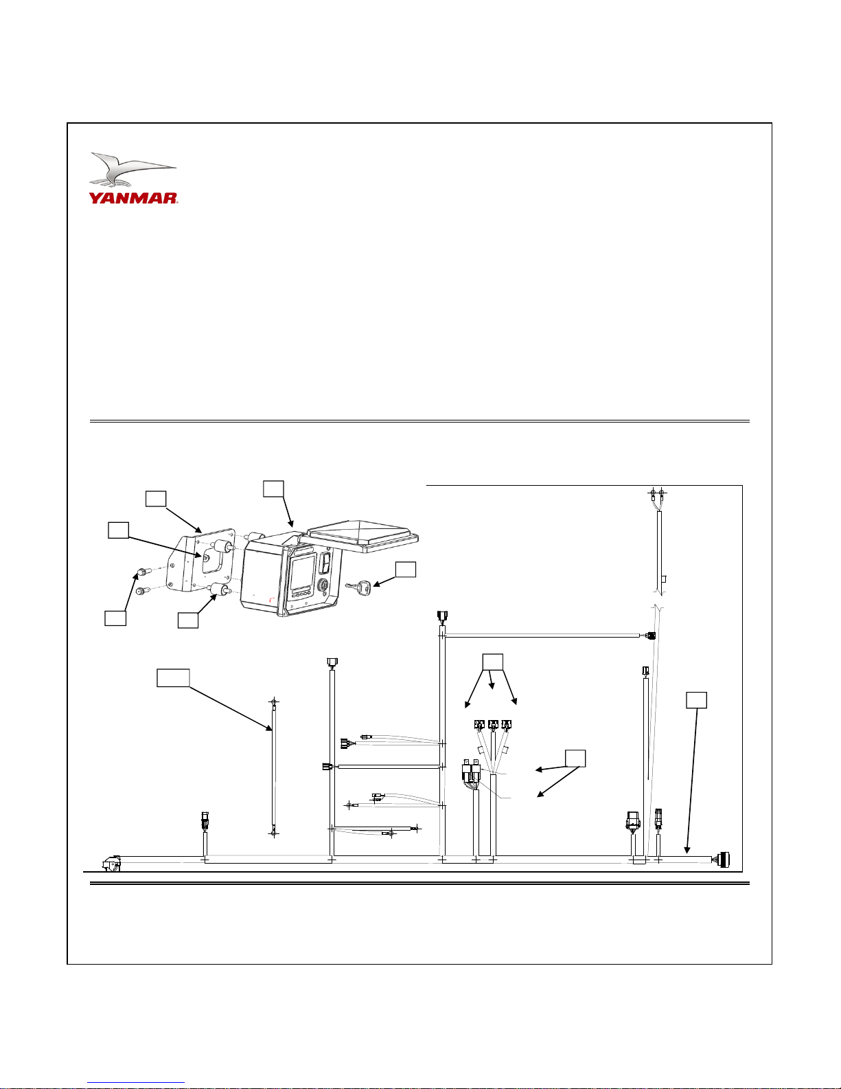
Item
1 1
2 2
3 1
4 1
5 0 Included w/ engine
6 2
7 1
8 2
9 2
10 1
11 1
119749-91040
119749-91050 Ignition Key, Engine Control Panel
119749-91060
119749-91001
198461-52950
129927-77930 70A, 12V Relay
129989-08010
26106-080252
26366-080002 Nut, M8 x 1.25 (Flanged hex head)
129989-09020 Alternator Sub Harness
INS-KP4-0012
Control Panel
Isolator Mount 1/4"-20 KIT
Wiring Harness (ECO)
Relay
Panel Mounting Bracket
Bolt, M8 x 1.25 - 25 (Flanged hex head)
Installation Document
QuantityPart No. Description
Remarks
MODELS
4TNV84T-Z
4TNV98-Z
4TNV98T-Z
7
1
9
2
8
3
10
Sub relay is optional and not included with the engine.
NOTE:
PAGE 1 OF 6
Main
Relay
J59
5
J60
Actuator
Relay
J63
Sub
Relay
CR4/J62
Preheat
Relay
CR3/J61
Starter
Relay
4
6
KP4 - PANEL KIT
INS-KP4-0012

Installation Instructions
A
YANMAR CO., LTD.
YANMAR AMERICA CORP.
NOTE:
Hand tighten all bolts and nuts until assembly is complet ed, then torque according to specifications in Table 1. The numbers in ()
represent the item numbers.
NOTE:
WARNING:
Only the Main and Rack Actuator Relays are required for the function of the Yanmar ECO engines. These relays are
supplied with the distributor standard specification engines in the loose parts box. The optional Sub-Relay connector (CR5)
is intended to activate 4 optional features such as engine stop switch, droop-switch, ECO lamp, and engine speed monitor.
All of these optional features are located in the accessory connector (J18) in the wire harness on pins 3,4,5, and 6. In the
event that these features need to be activated one additional relay P/N: 198461-52950 must be ordered from the Yanmar
merica Part Department.
Yanmar America Part Department Phone # : 1-800-966-7685
Fasten Control Panel (1) to the Mounting Bracket (7) using Isolators (3) and Nuts.
1.
Make sure isolators are not twisted during installation to avoid premature failure of components.
Assemble Control Panel (1) and Mounting Bracket (7) assembly to injection pump side front engine leg using M8 x 25 bolts
2.
(8) and M8 Flange Nuts (9).
The use of the KECMB1 kit is recommended for securing the ECU to the engine for proper harness routing and vibration
3.
resistance.
A relay mounting bracket has been provided with the kit. This bracket w ill allow the relays to be securely fastened to the
4.
engine to reduce vibration and water damage.
Please see the next page for detailed installation instructions.
Be sure battery cables are connected correctly. Disconnecting either the positive or negative battery cable while the
equipment is operating will cause premature failure of electronic components. Also, never weld on equipment wit h the
ECU connected to the wire harness.
NOTE:
Enabling Engine Speed Switch #1 -
Enabling Engine Speed Switch #2 -
Refer to harness drawing for additional design requirements for consideration of application. A troubleshooting guide is available
Table 1:
In the event that the 60" wire harness ex tension needs to be extended please follow the manufacturer's assembly and
wiring procedures. Please visit www.deutschip.com
more detailed procedure on how to properly assemble a connector. As always never use scotch locks or butt connectors to
Locate the 12 pin Deutsch accessory connector and jumper the pin #2 (ground) w it h pin #11 engine speed switch #1. Use
the female connector that comes attached t o eac h wire harness to make the connections. This will enable the Engine
Speed Switch #1 for constant speed.
Locate the 12 pin Deutsch accessory connector and jumper the pin #2 (ground) w it h pin #12 engine speed switch #2. Use
the female connector that comes attached t o eac h wire harness to make the connections. This will enable the Engine
Speed Switch #2 for constant speed.
For applications that remotely mount the ECU within the wire harnesses reach please use the following ECU mounting
guidelines:
1-
Install the ECU in a location that is not subject to steam or high-pressure water for cleaning
2-
Install the ECU in a location that is well ventilated and not subject to direct sunlight.
3-
Install the ECU so that the connector faces downward. Failure to do so may trap water in the connector, resulting in
corrosion of connector pins.
4-
Ensure no water is trapped inside the connector when plugging the connector. Water inside the connector may
corrode connector pins, resulting in malfunctioning of the ECU.
through Yanmar's Distributor Website or by contacting Yanmar America's Service Department.
Comply with torque standards in the t able to avoid unexpected damage during installation or in the future.
Diameter x Pitch Kgf-m
M5x0.8 0.4 ~ 0.7 3 ~ 5 4 ~ 6.7
M6 x 1.0 1.0~1.2 7~9 9.8~11.8
M8 x 1.25 1.5 ~ 2.9
M12 x 1.75 8.0 ~ 10.0
extend the wire harness. All extended wires must be soldered and sealed.
Constant Speed Applications:
Remote Mounted ECU Applications:
and click on the Connector Repair or Helpful Hints link to download a
Foot-lbf N-m
10.6 ~ 20.9 14.4 ~ 28.3
57.8 ~ 72.3 78.4 ~ 98.0
PAGE 2 OF 6
KP4 - PANEL KIT
INS-KP4-0012
 Loading...