

Page 1

TNE
UTILEV PN: 76000368
SERVICE MANUAL
4TNE92-NMH • 4TNE92-NMHA
4TNE98-NMH
TNE Service Manual
P/N: 0B2991-U0001
series
INDUSTRIAL
ENGINES
Page 2
English Language Manual Available
If you would like a copy of this manual in the English language, please contact your local authorized Yanmar
industrial engine dealer or distributor. A list of authorized Yanmar industrial engine dealers and distributors
can be found at http://www.yanmar.co.jp/english/index-network.htm. Note that authorized Yanmar
industrial engine dealers and distributors are indicated as “Land” under the “Sales Network” menu.
Disclaimers:
We reserve the right to change specifications and to improve our products without notice or obligation.
Yanmar and are registered trademarks of Yanmar Co., Ltd. in Japan, the United States and / or
other countries.
All Rights Reserved:
No part of this publication may be reproduced or used in any form by any means - graphic, electronic, or
mechanical, including photocopying, recording, taping, or information storage and retrieval systems - without
the written permission of Yanmar Co., Ltd.
© 2005 Yanmar Co. Ltd.
ii TNE Service Manual
Page 3

TABLE OF
CONTENTS
TNE Service Manual
Introduction ............................................................................................ 1-1
Yanmar Warranties ............................................................................... 2-1
Safety .................................................................................................... 3-1
General Service Information .................................................................. 4-1
Periodic Maintenance ............................................................................ 5-1
Engine ................................................................................................... 6-1
Fuel System .......................................................................................... 7-1
Cooling System ..................................................................................... 8-1
Lubrication System ................................................................................ 9-1
Starter Motor ....................................................................................... 10-1
Alternator ............................................................................................. 11-1
Electric Wiring ..................................................................................... 12-1
Troubleshooting ................................................................................... 13-1
TNE Service Manual
iii
Page 4

This Page Intentionally Left Blank
iv TNE Service Manual
Page 5

Section 1
INTRODUCTION
TNE Service Manual
This manual describes the service procedures for
the TNE series indirect injection engines. These
engines are certified by the U.S. EPA, California
ARB and/or the 97/68/EC Directive for industrial
use.
Please use this manual for accurate, quick and safe
servicing of the engine. Since the directions in this
manual are for a typical engine, some
specifications and components may be different
from your engine. Refer to the documentation
supplied by the optional equipment manufacturer
for specific service instructions.
Yanmar products are continuously undergoing
improvement. This Service Manual might not
address possible field modifications to the
equipment. Contact an authorized Yanmar
industrial engine dealer or distributor for answers to
any questions relating to field modifications.
TNE Service Manual
1-1
Page 6

INTRODUCTION
This Page Intentionally Left Blank
1-2 TNE Service Manual
Page 7

WARRANTIES
TNE Service Manual
Yanmar Limited Warranty................................................................ 2-3
What is Covered by this Warranty?........................................... 2-3
How Long is the Warranty Period?............................................ 2-3
What the Engine Owner Must Do:............................................. 2-3
To Locate an Authorized Yanmar Industrial Engine
Dealer or Distributor: ................................................................. 2-3
What Yanmar Will Do: ............................................................... 2-3
What is Not Covered by this Warranty? .................................... 2-4
Warranty Limitations:................................................................. 2-4
Warranty Modifications:............................................................. 2-4
Questions: ................................................................................. 2-4
Customer Registration............................................................... 2-4
Section 2
YANMAR
Table of Contents
Page
Yanmar Co., Ltd. Limited Emission Control
System Warranty - USA Only.......................................................... 2-5
Your Warranty Rights and Obligations: ..................................... 2-5
Manufacturer’s Warranty Period:............................................... 2-5
Warranty Coverage: .................................................................. 2-6
Warranted Parts: ....................................................................... 2-6
Exclusions: ................................................................................ 2-7
Owner’s Warranty Responsibilities:........................................... 2-7
TNE Service Manual
2-1
Page 8

YANMAR WARRANTIES
This Page Intentionally Left Blank
2-2 TNE Service Manual
Page 9

YANMAR WARRANTIES
YANMAR LIMITED WARRANTY
What is Covered by this Warranty?
Yanmar warrants to the original retail purchaser that your new Yanmar TNE Series Industrial Engine will be
free from defects in material and / or workmanship for the duration of the warranty period.
How Long is the Warranty Period?
The Yanmar standard limited warranty period begins on the date of the delivery of the new Yanmar TNE
Series Industrial Engine to the first retail purchaser and extends for a period of twenty-four (24) months or
two-thousand (2000) engine operation hours, whichever occurs first.
What the Engine Owner Must Do:
If you believe your Yanmar engine has experienced a failure due to a defect in material and / or
workmanship, you must contact an authorized Yanmar industrial engine dealer or distributor within thirty (30)
days of discovering the failure. You must provide proof of ownership of the engine, proof of the date of the
engine purchase and delivery, and documentation of the engine operation hours. You are responsible for the
transportation of the engine to and from the repair location as designated by Yanmar.
Yanmar strongly recommends you register your engine as soon as possible after purchase in order to
facilitate any future warranty matters.
To Locate an Authorized Yanmar Industrial Engine Dealer or Distributor:
You can locate your nearest authorized Yanmar industrial engine dealer or distributor by visiting the Yanmar
Corp., Ltd. web site at:
http://www.yanmar.co.jp
• The Japanese language page will be displayed. For English language “click” on “English Page.”
• “Click” on “Network” in the web site heading to view the “Yanmar Worldwide Network.”
• Choose and “Click” on the desired product group.
• “Click” on the Icon closest to your region.
• “Click” on the disired country or Associate company to locate your nearest authorized Yanmar industrial
engine dealer or distributor.
• You may also contact Yanmar by clicking on “Inquiry” in the web site heading.
What Yanmar Will Do:
Yanmar warrants to the original retail purchaser of a new Yanmar engine that Yanmar will make such repairs
and / or replacements necessary to correct any defects in materials and / or workmanship discovered during
the warranty period. Such repairs and / or replacements will be made at a location designated by Yanmar.
TNE Service Manual
2-3
Page 10

YANMAR WARRANTIES
Yanmar Limited Warranty - Continued
What is Not Covered by this Warranty?
This Warranty does not cover parts affected by or damaged by, but not limited to, accident, misuse, abuse,
“Acts of God,” neglect, improper installation, improper maintenance, improper storage, the use of unsuitable
attachments or parts, the use of contaminated fuels, the use of fuels, oils, lubricants, or fluids other than
those recommended in your Yanmar Operation Manual, unauthorized alterations or modifications, ordinary
wear and tear, and rust or corrosion. This Warranty does not cover the cost of parts and / or labor required to
perform normal / scheduled maintenance on your Yanmar engine. This Warranty does not cover consumable
parts such as, but not limited to filters, belts, hoses, fuel injector nozzles, lubricants and cleaning fluids.
Warranty Limitations:
The foregoing is Yanmar's only obligation to you and your exclusive remedy for breach of warranty.
Failure to follow the requirements for submitting a claim under this Warranty may result in a waiver of all
claims for damages and other relief. In no event shall Yanmar or any authorized industrial engine dealer
or distributor be liable for incidental, special or consequential damages. Such consequential damages
may include, but not be limited to, loss of revenue, loan payments, cost of rental of substitute equipment,
insurance coverage, storage, lodging, transportation, fuel, mileage and telephone costs. The limitations in
this Warranty apply regardless of whether your claims are based on breach of contract, tort (including
negligence and strict liability) or any other theory. Any action arising hereunder must be brought within one
(1) year after the cause of action accrues or it shall be barred. Some states and countries do not allow
certain limitations on warranties or for breach of warranties. This Warranty gives you specific legal rights,
and you may also have other rights which vary from state to state and country to country. Limitations
set forth in this paragraph shall not apply to the extent that they are prohibited by law.
Warranty Modifications:
Except as modified in writing and signed by the parties, this Warranty is and shall remain the complete and
exclusive agreement between the parties with respect to warranties, superseding all prior agreements,
written and oral, and all other communications between the parties relating to warranties. No person or
entity is authorized to give any other warranty or to assume any other obligation on behalf of
Yanmar, either orally or in writing.
Questions:
If you have any questions or concerns regarding this Warranty, please call or write to the nearest authorized
Yanmar industrial engine dealer or distributor or other authorized facility.
Customer Registration
Customer registration is very important for the original retail purchaser to enable Yanmar to provide
the best support for your engine.
At the time of purchase, Yanmar highly recommends registering the customer’s information through website
http://www.yanmar.co.jp
If it is not possible to access the website, please contact the nearest authorized Yanmar industrial engine
dealer or distributor.
as soon as possible.
2-4 TNE Service Manual
Page 11
YANMAR WARRANTIES
YANMAR CO., LTD. LIMITED EMISSION CONTROL SYSTEM
WARRANTY - USA ONLY
Your Warranty Rights and Obligations:
California
The California Air Resources Board (CARB) then Environmental Protection Agency (EPA) and Yanmar Co.,
Ltd. hereafter referred to as Yanmar, are pleased to explain the emission control system warranty on your
industrial compression-ignition engine. In California, model year 2000 or later off-road compression-ignition
engines must be designed, built and equipped to meet the State’s stringent anti-smog standards. In all
states, 1998 and later non-road compression-ignition engines must be designed, built and equipped to meet
the United States EPA emissions standards. Yanmar warrants the emission control system on your engine
for the periods of time listed below provided there has been no abuse, neglect or improper maintenance of
your engine.
Your emission control system may include parts such as the fuel injection system and the air induction
system. Also included may be hoses, belts, connectors and other emission-related assemblies.
Where a warrantable condition exists, Yanmar will repair your non-road compression-ignition engine at no
charge to you including diagnosis, parts and labor.
Manufacturer’s Warranty Period:
The model year 1998 or later certified and labeled non-road compression-ignition engines are warranted for
the periods listed below. If any emission-related part on your engine is found to be defective during the
applicable warranty period, the part will be replaced by Yanmar.
Engine Type Warranty Period by Number of Years or Hours of Operation
Constant speed engines rated at or above
50 hp (37 kW)
Constant speed engines rated under 50 hp
SAE (37 kW) with rated speeds greater than
or equal to 3,000 rpm
Engines rated at or above 26 hp (19 kW) Warranty period is five (5) years or 3,000 hours of use, whichever occurs first. In
Engines rated under 26 hp (19 kW) Warranty period is two (2) years or 3,000 hours of use, whichever occurs first. In
Warranty period is five (5) years or 3,000 hours of use, whichever occurs first. In
the absence of a device to measure hours of use, the engine has a warranty
period of five (5) years.
Warranty period is two (2) years or 3,000 hours of use, whichever occurs first. In
the absence of a device to measure hours of use, the engine has a warranty
period of two (2) years.
the absence of a device to measure hours of use, the engine has a warranty
period of five (5) years.
the absence of a device to measure hours of use, the engine has a warranty
period of two (2) years.
TNE Service Manual
2-5
Page 12

YANMAR WARRANTIES
Limited Emission Control System Warranty - USA Only - Continued
Warranty Coverage:
This warranty is transferable to each subsequent purchaser for the duration of the warranty period. Repair or
replacement of any warranted part will be performed at an authorized Yanmar dealer.
Warranted parts not scheduled for replacement as required maintenance in the Operation Manual shall be
warranted for the warranty period. Warranted parts scheduled for replacement as required maintenance in
the owner’s manual are warranted for the period of time prior to the first scheduled replacement. Any part
repaired or replaced under warranty shall be warranted for the remaining warranty period.
During the warranty period, Yanmar is liable for damages to other engine components caused by the failure
of any warranted part during the warranty period.
Any replacement part which is functionally identical to the original equipment part in all respects may be
used in the maintenance or repair of your engine, and shall not reduce Yanmar’s warranty obligations.
Add-on or modified parts that are not exempted may not be used. The use of any non-exempted add-on or
modified parts shall be grounds for disallowing a warranty.
Warranted Parts:
This warranty covers engine components that are a part of the emission control system of the engine as
delivered by Yanmar to the original retail purchaser. Such components may include the following:
• Fuel Injection System
• Cold Start Enrichment System
• Intake Manifold
• Turbocharger Systems
• Exhaust Manifold
• Positive Crankcase Ventilation System
• Hoses, belts, connectors and assemblies associated with emission control systems
Since emissions related parts may vary slightly between models, certain models may not contain all of these
parts and other models may contain the functional equivalents.
2-6 TNE Service Manual
Page 13

Limited Emission Control System Warranty - USA Only - Continued
YANMAR WARRANTIES
Exclusions:
Failures other than those arising from defects in
material and / or workmanship are not covered by
this warranty. The warranty does not extend to the
following: malfunctions caused by abuse, misuse,
improper adjustment, modification, alteration,
tampering, disconnection, improper or inadequate
maintenance or use of non-recommended fuels
and lubricating oils; accident-caused damage, and
replacement of expendable items made in
connection with scheduled maintenance. Yanmar
disclaims any responsibility for incidental or
consequential damages such as loss of time,
inconvenience, loss of use of equipment / engine or
commercial loss.
Owner’s Warranty Responsibilities:
As the engine owner, you are responsible for
the performance of the required maintenance
listed in your owner’s manual. Yanmar
recommends that you retain all documentation,
including receipts, covering maintenance on your
non-road compression-ignition engine, but Yanmar
cannot deny warranty solely for the lack of receipts,
or for your failure to ensure the performance of all
scheduled maintenance.
Yanmar may deny your warranty coverage of your
non-road compression-ignition engine or a part has
failed due to abuse, neglect, improper maintenance
or unapproved modifications.
Your engine is designed to operate on diesel fuel
only. Use of any other fuel may result in your engine
no longer operating in compliance with applicable
emissions requirements.
You are responsible for initiating the warranty
process. You must present your engine to a Yanmar
dealer as soon as a problem exists. The warranty
repairs should be completed by the dealer as
expeditiously as possible. If you have any questions
regarding your warranty rights and responsibilities,
or would like information on the nearest Yanmar
dealer or authorized service center, you should
contact Yanmar America Corporation at
1-800-872-2867.
TNE Service Manual
2-7
Page 14

YANMAR WARRANTIES
This Page Intentionally Left Blank
2-8 TNE Service Manual
Page 15
TNE Service Manual
Section 3
SAFETY
SAFETY STATEMENTS
Yanmar is concerned for your safety and your
machine’s condition. Safety statements are one of
the primary ways to call your attention to the
potential hazards associated with Yanmar TNE
engine operation. Follow the precautions listed
throughout the manual before operation, during
operation and during periodic maintenance
procedures for your safety, the safety of others and
to protect the performance of your engine. Keep the
labels from becoming dirty or torn and replace
them if they are lost or damaged. Also, if you need
to replace a part that has a label attached to it,
make sure you order the new part and label at the
same time.
This safety alert symbol appears with
most safety statements. It means
A
attention, become alert, your safety is
involved! Please read and abide by the
message that follows the safety alert
symbol.
A DANGER
Danger (the word “DANGER” is in white
letters with a red rectangle behind it) –
indicates an imminently hazardous
situation which, if not avoided, will
result in death or serious injury. Danger
is limited to the most extreme
situations.
0000001en
A WARNING
Warning (the word “WARNING” is in
black letters with an orange rectangle
behind it) – indicates a potentially
hazardous situation which, if not
avoided, could result in death or serious
injury.
0000001en
A CAUTION
Caution (the word “CAUTION” is in black
letters with a yellow rectangle behind it)
– indicates a potentially hazardous
situation which, if not avoided, may
result in minor or moderate injury.
0000001en
CAUTION
Caution without the safety alert symbol
indicates a potentially hazardous
situation that can cause damage to the
machine, personal property and / or the
environment or cause the machine to
operate improperly.
0000001en
TNE Service Manual
3-1
Page 16
SAFETY
SAFETY PRECAUTIONS
Before You Operate
CAUTION
NEVER permit anyone to operate the
engine or driven machine without proper
training.
• Read and understand this Operation
Manual before you operate the
machine to ensure that you follow safe
operating practices and maintenance
procedures.
• Machine safety signs and labels are
additional reminders for safe operating
and maintenance techniques.
• See your authorized Yanmar industrial
engine dealer or distributor for
additional training.
0000002en
During Operation and Maintenance
A DANGER
SCALD HAZARD!
• NEVER remove the radiator cap if the
engine is hot. Steam and hot engine
coolant will spurt out and seriously
burn you. Allow the engine to cool
down before you attempt to remove
the radiator cap.
• Securely tighten the radiator cap after
you check the radiator. Steam can
spurt out during engine operation if
the cap is loose.
• ALWAYS check the level of engine
coolant by observing the reserve tank.
• Failure to comply will result in death or
serious injury.
0000002en
A DANGER
EXPLOSION HAZARD!
• Keep the area around the battery well
ventilated. While the engine is running
or the battery is charging, hydrogen
gas is produced which can be easily
ignited.
• Keep sparks, open flame and any other
form of ignition away.
• Failure to comply will result in death or
serious injury.
0000003en
3-2 TNE Service Manual
Page 17
SAFETY
A DANGER
FIRE AND EXPLOSION HAZARD!
• Diesel fuel is extremely flammable and
explosive under certain conditions.
• When you remove any fuel system
component to perform maintenance
(such as changing the fuel filter) place
an approved container under the
opening to catch the fuel.
• NEVER use a shop rag to catch the
fuel. Vapors from the rag are extremely
flammable and explosive.
• Wipe up any spills immediately.
• Wear eye protection. The fuel system
is under pressure and fuel could spray
out when you remove any fuel system
component.
A DANGER
FIRE AND EXPLOSION HAZARD!
• Diesel fuel is extremely flammable and
explosive under certain conditions.
• NEVER remove the fuel cap with
engine running.
• Failure to comply will result in death or
serious injury.
0000011en
• Failure to comply will result in death or
serious injury.
0000009en
A DANGER
FIRE AND EXPLOSION HAZARD!
• Diesel fuel is extremely flammable and
explosive under certain conditions.
• NEVER use diesel fuel as a cleaning
agent.
• Failure to comply will result in death or
serious injury.
0000012en
TNE Service Manual
3-3
Page 18
SAFETY
A DANGER
FIRE AND EXPLOSION HAZARD!
• Diesel fuel is extremely flammable and
explosive under certain conditions.
• Place an approved container under the
air bleed port when you prime the fuel
system. Never use a shop rag to catch
the fuel. Wipe up any spills
immediately. ALWAYS close the air
bleed port after you complete priming
the system.
• Wear eye protection. The fuel system
is under pressure and fuel could spray
out when you open the air bleed port.
• If the unit has an electric fuel pump,
turn the key switch to the ON position
for 10 to 15 seconds, or until the fuel
coming out of the air bleed port is free
of bubbles, to allow the electric fuel
pump to prime the system.
• If the unit has a mechanical fuel pump,
operate the fuel priming pump several
times until the fuel coming out of the
air bleed port is free of bubbles.
• Failure to comply will result in death or
serious injury.
0000006en
A DANGER
FIRE AND EXPLOSION HAZARD!
• Only use the key switch to start the
engine.
• NEVER jump start the engine. Sparks
caused by jumping the battery to the
starter terminals may cause a fire or
explosion.
• Failure to comply will result in death or
serious injury.
0000004en
0
A DANGER
FIRE AND EXPLOSION HAZARD!
• Diesel fuel is extremely flammable and
explosive under certain conditions.
• Only fill fuel tank with diesel fuel.
Filling fuel tank with gasoline may
result in a fire.
• NEVER refuel with engine running.
• Wipe up all spills immediately.
• Keep sparks, open flames or any other
form of ignition (match, cigarette,
static electric source) away when
fueling / refueling.
• NEVER overfill the fuel tank.
• Fill fuel tank and store fuel in a
well-ventilated area only.
• Failure to comply will result in death or
serious injury.
3-4 TNE Service Manual
0000005en
Page 19
SAFETY
0
A DANGER
FIRE AND EXPLOSION HAZARD!
• Diesel fuel is extremely flammable and
explosive under certain conditions.
• Before you operate the engine, check
for fuel leaks. Replace rubberized fuel
hoses every two years or every 2000
hours of engine operation, whichever
comes first, even if the engine has
been out of service. Rubberized fuel
lines tend to dry out and become
brittle after two years or 2000 hours of
engine operation, whichever comes
first.
• Failure to comply will result in death or
serious injury.
0000015en
A DANGER
CRUSH HAZARD!
• When you need to transport an engine
for repair have a helper assist you
attach it to a hoist and load it on a
truck.
• NEVER stand under hoisted engine. If
the hoist mechanism fails, the engine
will fall on you, causing serious injury
or death.
• Failure to comply will result in death or
serious injury.
0000008en
A DANGER
EXPLOSION HAZARD!
• NEVER check the remaining battery
charge by shorting out the terminals.
This will result in a spark and may
cause an explosion or fire. Use a
hydrometer to check the remaining
battery charge.
• If the electrolyte is frozen, slowly warm
the battery before you recharge it.
• Failure to comply will result in death or
serious injury.
0000007en
TNE Service Manual
3-5
Page 20
SAFETY
A WARNING
SEVER HAZARD!
• Keep hands and other body parts
away from moving / rotating parts
such as the cooling fan, flywheel or
PTO shaft.
• Wear tight fitting clothing and keep
your hair short or tie it back while the
engine is running.
• Remove all jewelry before you operate
or service the machine.
• NEVER start the engine in gear.
Sudden movement of the engine
and / or machine could cause death or
serious personal injury.
• NEVER operate the engine without the
guards in place.
• Before you start the engine make sure
that all bystanders are clear of the
area.
A WARNING
EXHAUST HAZARD!
• NEVER operate the engine in an
enclosed area such as a garage,
tunnel, underground room, manhole or
ship’s hold without proper ventilation.
• NEVER block windows, vents, or other
means of ventilation if the engine is
operating in an enclosed area. All
internal combustion engines create
carbon monoxide gas during
operation. Accumulation of this gas
within an enclosure could cause
illness or even death.
• Make sure that all connections are
tightened to specifications after repair
is made to the exhaust system.
• Failure to comply could result in death
or serious injury.
0000003en
• Keep children and pets away while the
engine is operating.
• Check before starting the engine that
any tools or shop rags used during
maintenance have been removed from
the area.
• Failure to comply could result in death
or serious injury.
0000002en
A WARNING
ALCOHOL AND DRUG HAZARD!
• NEVER operate the engine while you
are
under the influence of alcohol or
drugs.
• NEVER operate the engine when you
are feeling ill.
• Failure to comply could result in death
or serious injury.
0000004en
3-6 TNE Service Manual
Page 21
SAFETY
A WARNING
EXPOSURE HAZARD!
• Wear personal protective equipment
such as gloves, work shoes, eye and
hearing protection as required by the
task at hand.
• NEVER wear jewelry, unbuttoned
cuffs, ties or loose fitting clothing
when you are working near
moving / rotating parts such as the
cooling fan, flywheel or PTO shaft.
• ALWAYS tie long hair back when you
are working near moving / rotating
parts such as a cooling fan, flywheel,
or PTO shaft.
• NEVER operate the engine while
wearing a headset to listen to music or
radio because it will be difficult to hear
warning signals.
A WARNING
BURN HAZARD!
• Batteries contain sulfuric acid. NEVER
allow battery fluid to come in contact
with clothing, skin or eyes. Severe
burns could result. ALWAYS wear
safety goggles and protective clothing
when servicing the battery. If contact
with the skin and / or eyes should
occur, flush with a large amount of
water and obtain prompt medical
treatment.
• Failure to comply could result in death
or serious injury.
0000007en
A WARNING
• Failure to comply could result in death
or serious injury.
0000005en
HIGH PRESSURE HAZARD!
• Avoid skin contact with high pressure
diesel fuel spray caused by a fuel
system leak such as a broken fuel
injection line. High pressure fuel can
penetrate your skin and result in
serious injury. If you are exposed to
high pressure fuel spray obtain
prompt medical treatment.
• NEVER check for a fuel leak with your
hands. ALWAYS use a piece of wood
or cardboard. Have your authorized
Yanmar industrial engine dealer or
distributor repair the damage.
• Failure to comply could result in death
or serious injury.
0000008en
TNE Service Manual
3-7
Page 22
SAFETY
A WARNING
SHOCK HAZARD!
• Turn off the battery switch (if
equipped) or disconnect the negative
battery cable before servicing the
electrical system.
• Check the electrical harnesses for
cracks, abrasions, and damaged or
corroded connectors. ALWAYS keep
the connectors and terminals clean.
• Failure to comply could result in death
or serious injury.
0000009en
A WARNING
A WARNING
BURN HAZARD!
• If you must drain the engine oil while it
is still hot, stay clear of the hot engine
oil to avoid being scalded. Make sure
you wear eye protection.
• Failure to comply could result in death
or serious injury.
0000011en
A WARNING
BURN HAZARD!
SEVER HAZARD!
• Stop the engine before you begin to
service it.
• NEVER leave the key in the key switch
when you are servicing the engine.
Someone may accidentally start the
engine and not realize you are
servicing it. This could result in a
serious injury.
• If you must service the engine while it
is operating, remove all jewelry, tie
back long hair, and keep your hands,
other body parts and clothing away
from moving / rotating parts.
• Failure to comply could result in death
or serious injury.
0000010en
• Wait until the engine cools before you
drain the engine coolant. Hot engine
coolant may splash and burn you.
• Failure to comply could result in death
or serious injury.
0000016en
3-8 TNE Service Manual
Page 23
SAFETY
A WARNING
BURN HAZARD!
• Keep your hands, and other body
parts, away from hot engine surfaces
such as the muffler, exhaust pipe,
turbocharger (if equipped) and engine
block during operation and shortly
after you shut the engine down. These
surfaces are extremely hot while the
engine is operating and could
seriously burn you.
• Failure to comply could result in death
or serious injury.
0000015en
A CAUTION
A CAUTION
FLYING OBJECT HAZARD!
• ALWAYS wear eye protection when
servicing engine and when using
compressed air or high-pressure
water. Dust, flying debris, compressed
air, pressurized water or steam may
injure your eyes.
• Failure to comply may result in minor
or moderate injury.
0000003en
CAUTION
• Only use diesel fuels recommended by
Yanmar for the best engine
performance, to prevent engine
damage and to comply with EPA / ARB
warranty requirements.
COOLANT HAZARD!
• Wear eye protection and rubber gloves
when you handle Long Life or
Extended Life engine coolant. If
contact with the eyes or skin should
occur, wash immediately with clean
water.
• Failure to comply may result in minor
or moderate injury.
0000005en
• Only use clean diesel fuel.
• NEVER remove primary strainer from
the fuel tank filler port (if equipped). If
removed, dirt and debris could get into
the fuel system causing it to clog.
0000004en
CAUTION
NEVER attempt to adjust the low or high
idle speed limit screw. This may impair
the safety and performance of the
machine and shorten its life. If
adjustment is ever required, contact
your authorized Yanmar industrial
engine dealer or distributor.
0000045en
TNE Service Manual
3-9
Page 24
SAFETY
CAUTION
If any problem is noted during the visual
check, the necessary corrective action
should be taken before you operate the
engine.
0000021en
CAUTION
NEVER hold the key in the START
position for longer than 15 seconds or
the starter motor will overheat.
0000007en
CAUTION
The illustrations and descriptions of
optional equipment in this manual, such
as the operator’s console, are for a
typical engine installation. Refer to the
documentation supplied by the optional
equipment manufacturer for specific
operation and maintenance instructions.
0000018en
CAUTION
Observe the following environmental
operating conditions to maintain engine
performance and avoid premature
engine wear:
• Avoid operating in extremely dusty
conditions.
• Avoid operating in the presence of
chemical gases or fumes.
• Avoid operating in a corrosive
atmosphere such as salt water spray.
• NEVER install the engine in a
floodplain unless proper precautions
are taken to avoid being subject to a
flood.
• NEVER expose the engine to the rain.
0000003enTNE
CAUTION
If any indicator illuminates during
engine operation stop the engine
immediately. Determine the cause and
repair the problem before you continue
to operate the engine.
0000029en
3-10 TNE Service Manual
Page 25
SAFETY
CAUTION
Observe the following environmental
operating conditions to maintain engine
performance and avoid premature
engine wear:
• NEVER run the engine if the ambient
temperature is above +104°F (+40°C)
or below +5°F (-15°C).
◆ If the ambient temperature exceeds
+104°F (+40°C) the engine may
overheat and cause the engine oil to
break down.
◆ If the ambient temperature falls
below +5°F (-15°C) rubber
components such as gaskets and
seals will harden causing premature
engine wear and damage.
◆ Contact your authorized Yanmar
industrial engine dealer or
distributor if the engine will be
operated in either temperature
extreme.
• Contact your authorized Yanmar
industrial engine dealer or distributor
if you need to operate the engine at
high altitudes. At high altitudes the
engine will lose power, run rough, and
produce exhaust gases that exceed
the design specifications.
0000065enTNE
CAUTION
• Only use the engine oil specified.
Other engine oils may affect warranty
coverage, cause internal engine
components to seize, or shorten
engine life.
• Prevent dirt and debris from
contaminating engine oil. Carefully
clean the oil cap / dipstick and the
surrounding area before you remove
the cap.
• NEVER mix different types of engine
oil. This may adversely affect the
lubricating properties of the engine oil.
• NEVER overfill. Overfilling may result
in white exhaust smoke, engine
overspeed or internal damage.
0000005en
CAUTION
• Only use the engine coolant specified.
Other engine coolants may affect
warranty coverage, cause an internal
build up of rust and scale and / or
shorten engine life.
• Prevent dirt and debris from
contaminating engine coolant.
Carefully clean the radiator cap and
the surrounding area before you
remove the cap.
TNE Service Manual
• NEVER mix different types of engine
coolants. This may adversely affect the
properties of the engine coolant.
0000006en
CAUTION
• NEVER overfill the engine with engine
oil.
• ALWAYS keep the oil level between
upper and lower lines on the dipstick.
0000015en
3-11
Page 26
SAFETY
CAUTION
For maximum engine life, Yanmar
recommends that when shutting the
engine down, you allow the engine to
idle, without load, for 5 minutes. This
will allow the engine components that
operate at high temperatures, such as
the turbocharger (if equipped) and
exhaust system, to cool slightly before
the engine itself is shut down.
0000008en
CAUTION
NEVER use an engine starting aid such
as ether. Engine damage will result.
0000009en
CAUTION
Make sure the engine is installed on a
level surface. If a continuously running
engine is installed at an angle greater
than 20° (in any direction) or if an engine
runs for short periods of time (less than
3 minutes) at an angle greater than 25°
in any direction, engine oil may enter the
combustion chamber causing exessive
engine speed and generate white
smoke. This may cause serious engine
damage.
0000010enTNE
CAUTION
New Engine Break In:
• On the initial engine start-up, allow the
engine to idle for approximately 15
minutes while you check for proper
engine oil pressure, diesel fuel leaks,
engine oil leaks, coolant leaks, and for
proper operation of the indicators
and / or gauges.
• During the first hour of operation, vary
the engine speed and load on the
engine. Short periods of maximum
engine speed and load are desirable.
Avoid prolonged operation at
minimum or maximum engine speeds
and loads for the next 4 to 5 hours.
• During the break-in period, carefully
observe the engine oil pressure and
engine temperature.
• During the break-in period, check the
engine oil and coolant levels
frequently.
0000011en
CAUTION
NEVER engage the starter motor while
the engine is running. This may damage
the starter motor pinion and / or ring
gear.
0000012en
3-12 TNE Service Manual
Page 27
SAFETY
CAUTION
• NEVER attempt to modify the engine’s
design or safety features such as
defeating the engine speed limit
control or the fuel injection quantity
control.
• Failure to comply may impair the
engine’s safety and performance
characteristics and shorten the
engine’s life. Any alterations to this
engine may affect the warranty
coverage of your engine. See Yanmar
Limited Warranty on page 2-3.
0000044enTNESM
CAUTION
Be environmentally responsible. Follow
these procedures for hazardous waste
disposal. Failure to follow these
procedures may seriously harm the
environment.
• Follow the guidelines of the EPA or
other governmental agency for the
proper disposal of hazardous
materials such as engine oil, diesel
fuel and engine coolant. Consult the
local authorities or reclamation facility.
• NEVER dispose of hazardous
materials irresponsibly by dumping
them into a sewer, on the ground or
into ground water or waterways.
0000013en
CAUTION
Protect the air cleaner, turbocharger (if
equipped) and electric components
from damage when you use steam or
use high-pressure water to clean the
engine.
0000014en
CAUTION
NEVER use high pressure water or
compressed air at greater than 28 psi or
a wire brush to clean the radiator fins.
Radiator fins damage easily.
0000016en
CAUTION
NEVER attempt to adjust the low or high
idle speed limit screw. This may impair
the safety and performance of the
machine and shorten its life. If the idle
speed limit screws require adjustment,
see your authorized Yanmar industrial
engine dealer or distributor.
0000017en
CAUTION
The tightening torque in the Standard
Torque Chart (page 5-17) should be
applied only to the bolts with a “7” head.
(JIS strength classification: 7T)
• Apply 60% torque to
bolts that are not listed.
• Apply 80% torque when
tightened to aluminum alloy.
0000023enTNESM
TNE Service Manual
3-13
Page 28
SAFETY
CAUTION
If any indicator fails to illuminate when
the key switch is in the ON position, see
your authorized Yanmar industrial
engine dealer or distributor for service
before operating the engine.
0000028en
CAUTION
Establish a periodic maintenance plan
according to the engine application and
make sure you perform the required
periodic maintenance at intervals
indicated. Failure to follow these
guidelines will impair the engine’s safety
and performance characteristics,
shorten the engine’s life and may affect
the warranty coverage on your engine.
See Yanmar Limited Warranty on
page 2-3.
Consult your authorized Yanmar
industrial engine dealer or distributor for
assistance when checking items marked
with a
z.
0000024enTNESM
CAUTION
It is important to perform daily checks
See Daily on page 5-19.
Periodic maintenance prevents
unexpected downtime, reduces the
number of accidents due to poor
machine performance and helps extend
the life of the engine.
0000060enTNESM
CAUTION
If the fuel filter / water separator is
positioned higher than the fuel level in
the fuel tank, water may not drip out
when the fuel filter / water separator
drain cock is opened. If this happens,
turn the air vent screw on the top of the
fuel filter / water separator 2-3 turns
counterclockwise.
Be sure to tighten the air vent screw
after the water has drained out.
0000025en
CAUTION
• When the engine is operated in dusty
conditions, clean the air cleaner
element more frequently.
• NEVER operate the engine with the air
cleaner or element(s) removed. This
may cause foreign material to enter the
engine and damage it.
0000026en
CAUTION
The maximum air intake restriction shall
be 0.90 psi (6.23 kPa; 635 mm Aq) or
less. Clean or replace the air cleaner
element if the air intake restriction
exceeds the above mentioned value.
0000046en
CAUTION
NEVER turn off the battery switch (if
equipped) or short the battery cables
during operation. Damage to the electric
system will result.
0000061en
3-14 TNE Service Manual
Page 29

Section 4
GENERAL SERVICE
INFORMATION
TNE Service Manual
Table of Contents
Component Identification................................................................. 4-3
Location of Labels ........................................................................... 4-3
EPA / ARB Emission Control Regulations - USA Only.................... 4-4
Emission Control Labels.................................................................. 4-4
EPA / ARB Labels ..................................................................... 4-4
The 97/68/EC Directive Certified Engines....................................... 4-4
Engine Family.................................................................................. 4-5
Page
Function of Major Engine Components ........................................... 4-6
Function of Cooling System Components ....................................... 4-8
Diesel Fuel ...................................................................................... 4-9
Diesel Fuel Specifications ......................................................... 4-9
Filling The Fuel Tank............................................................... 4-10
Priming the Fuel System ......................................................... 4-12
Engine Oil...................................................................................... 4-14
Engine Oil Specifications......................................................... 4-14
Engine Oil Viscosity................................................................. 4-14
Checking Engine Oil................................................................ 4-15
Adding Engine Oil.................................................................... 4-15
Engine Oil Capacity (Typical) .................................................. 4-15
Engine Coolant.............................................................................. 4-16
Engine Coolant Specifications................................................. 4-16
Filling Radiator With Engine Coolant....................................... 4-17
Engine Coolant Capacity (Typical) .......................................... 4-18
Specifications ................................................................................ 4-19
Description of Model Number.................................................. 4-19
TNE Service Manual
4-1
Page 30

GENERAL SERVICE INFORMATION
Engine Speed Specifications................................................... 4-19
Engine General Specifications ................................................ 4-19
Principal Engine Specifications ..................................................... 4-20
4TNE92-NMH.......................................................................... 4-20
4TNE92-NMHA ....................................................................... 4-21
4TNE98-NMH.......................................................................... 4-22
Engine Service Information ........................................................... 4-23
Engine Tuning ......................................................................... 4-23
Tightening Torques for Standard Bolts and Nuts .......................... 4-24
Standard Torque Chart.................................................................. 4-25
Abbreviations and Symbols........................................................... 4-26
Abbreviations........................................................................... 4-26
Symbols................................................................................... 4-26
Unit Conversions........................................................................... 4-27
Unit Prefixes ............................................................................ 4-27
Units of Length ........................................................................ 4-27
Units of Volume ....................................................................... 4-27
Units of Mass........................................................................... 4-27
Units of Force .......................................................................... 4-27
Units of Torque........................................................................ 4-27
Units of Pressure..................................................................... 4-27
Units of Power ......................................................................... 4-27
Units of Temperature............................................................... 4-27
4-2 TNE Service Manual
Page 31
GENERAL SERVICE INFORMATION
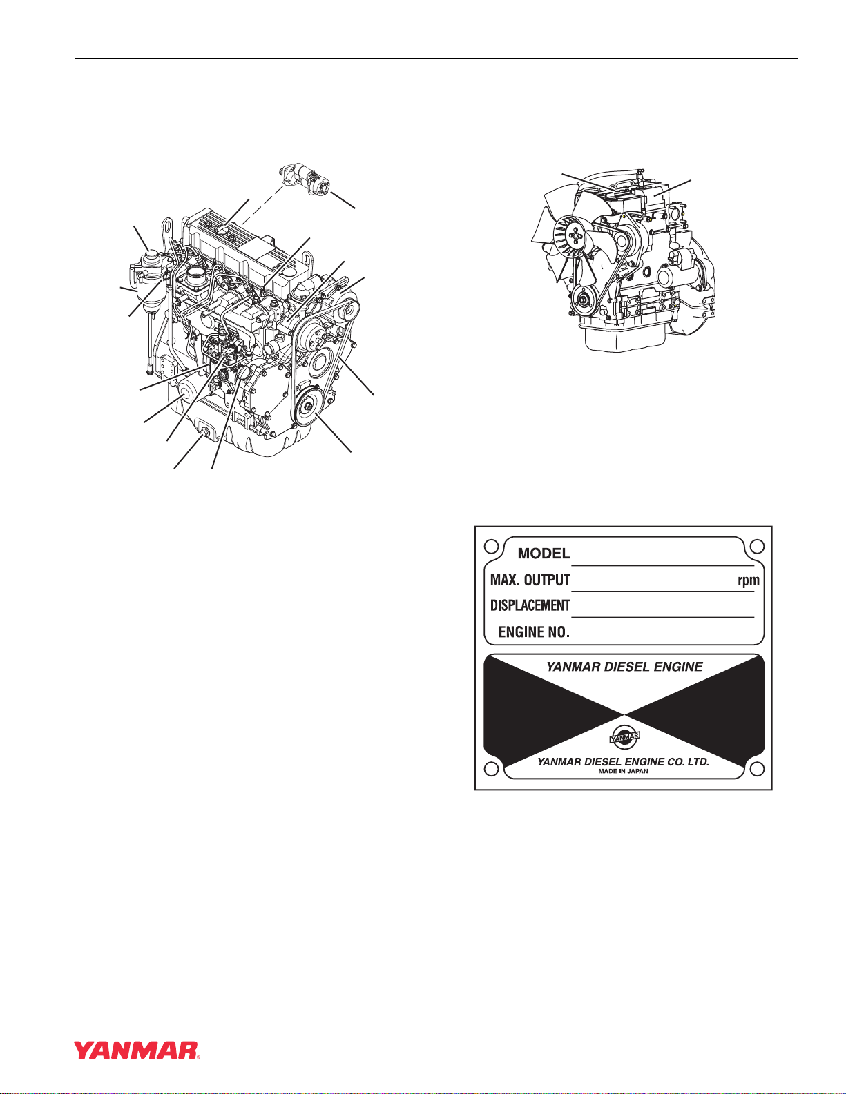
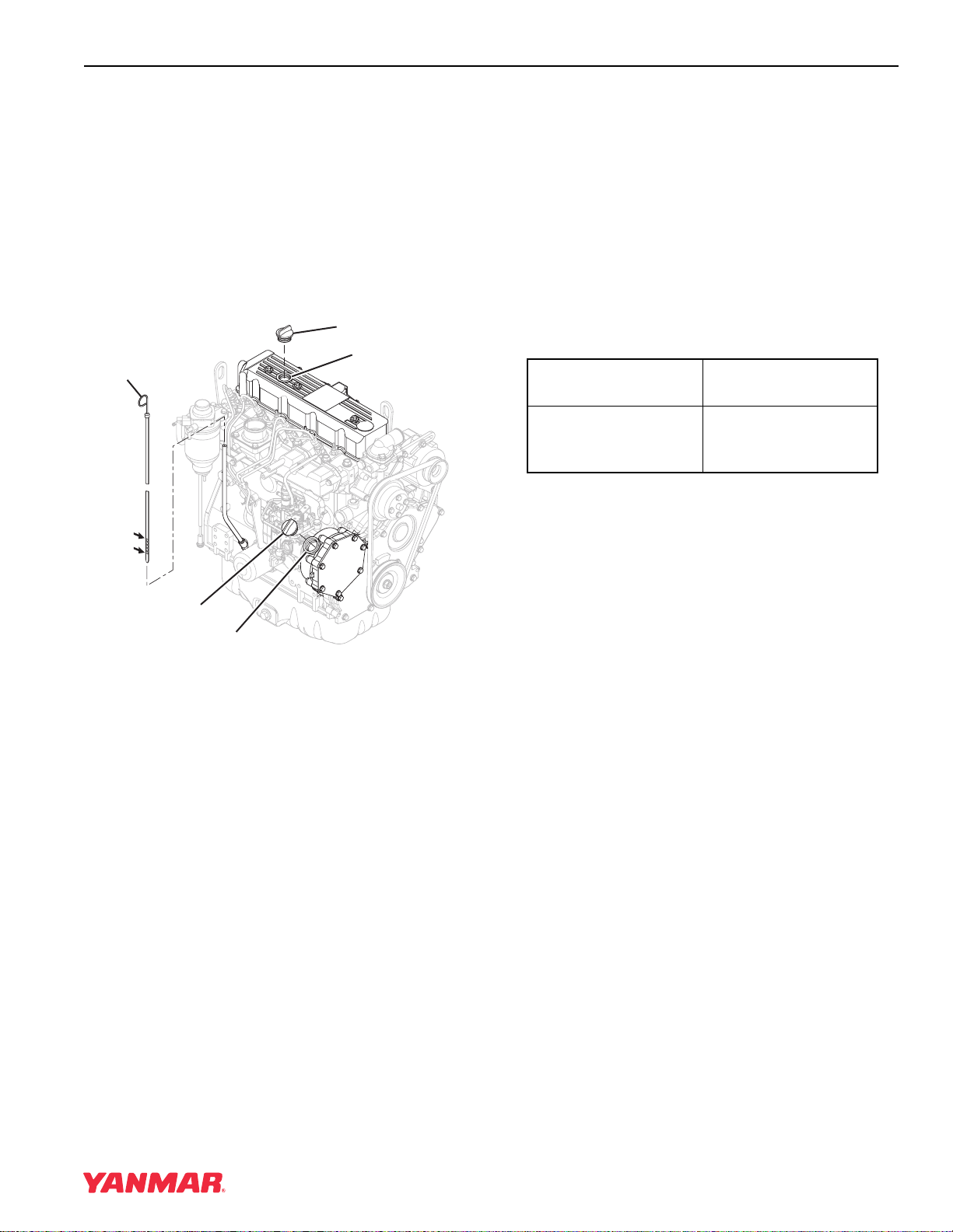
COMPONENT IDENTIFICATION
Figure 4-1 shows where major engine components
are located.
(2)
(15)
(10)
(11)
(13)
(14)
0001102A
(1)
(6)
(9)
(4)
(8)
(3)
(7)
(12)
(5)
Figure 4-1
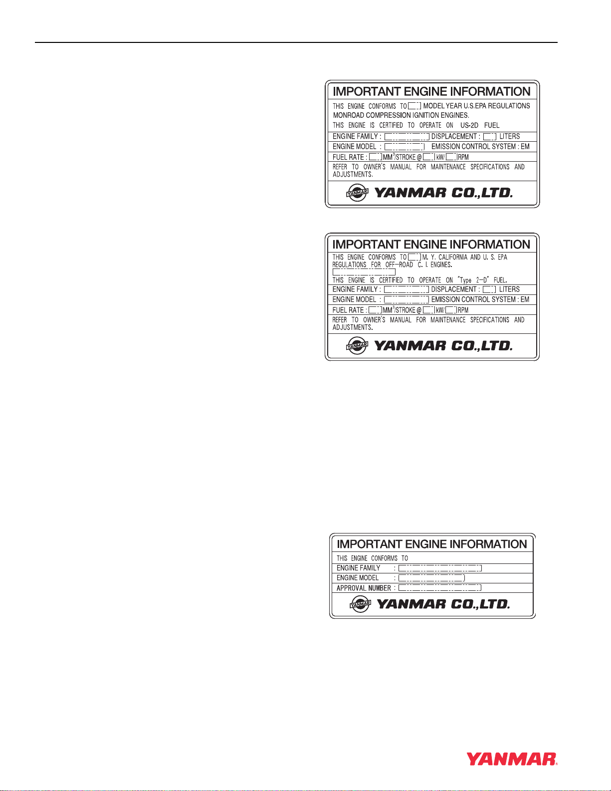
LOCATION OF LABELS
Figure 4-2 shows the location of regulatory and
safety labels on Yanmar TNE series engines.
(2)
Figure 4-2
The typical location of the emission control
information label is shown (Figure 4-2, (1)).
Typical location of the engine nameplate is shown
(Figure 4-2, (2)).
Engine Nameplate (Typical)
(1)
0000585A
1. Fuel Filter / Water
Separator
2. Top Filler Port
(Engine Oil)
3. Governor Lever
4. Fuel Injection
Pump
5. Side Filler Port
(Engine Oil)
6. Fuel Priming
Pump
7. Drain Plug
(Engine Oil)
8. Engine Oil Filter
9. Dipstick
(Engine Oil)
10. Engine Coolant
Pump
11. Alternator
12. Glow Plug
13. V-Belt
14. Crankshaft
V-Pulley
15. Starter Motor
0000287
TNE Service Manual
4-3
Page 32
GENERAL SERVICE INFORMATION
EPA / ARB EMISSION CONTROL REGULATIONS - USA ONLY
Yanmar TNE engines meet Environmental
Protection Agency (EPA) (U. S. Federal) emission
control standards as well as the California Air
Resources Board (ARB, California) regulations.
Only engines that conform to ARB regulations can
be sold in the State of California.
Refer to the specific EPA / ARB installation (page
5-16) and maintenance (page 5-16) in the
Periodic Maintenance section of this manual. Also
refer to the Yanmar Co., Ltd. Limited Emission
Control System Warranty - USA Only on page 2-5.
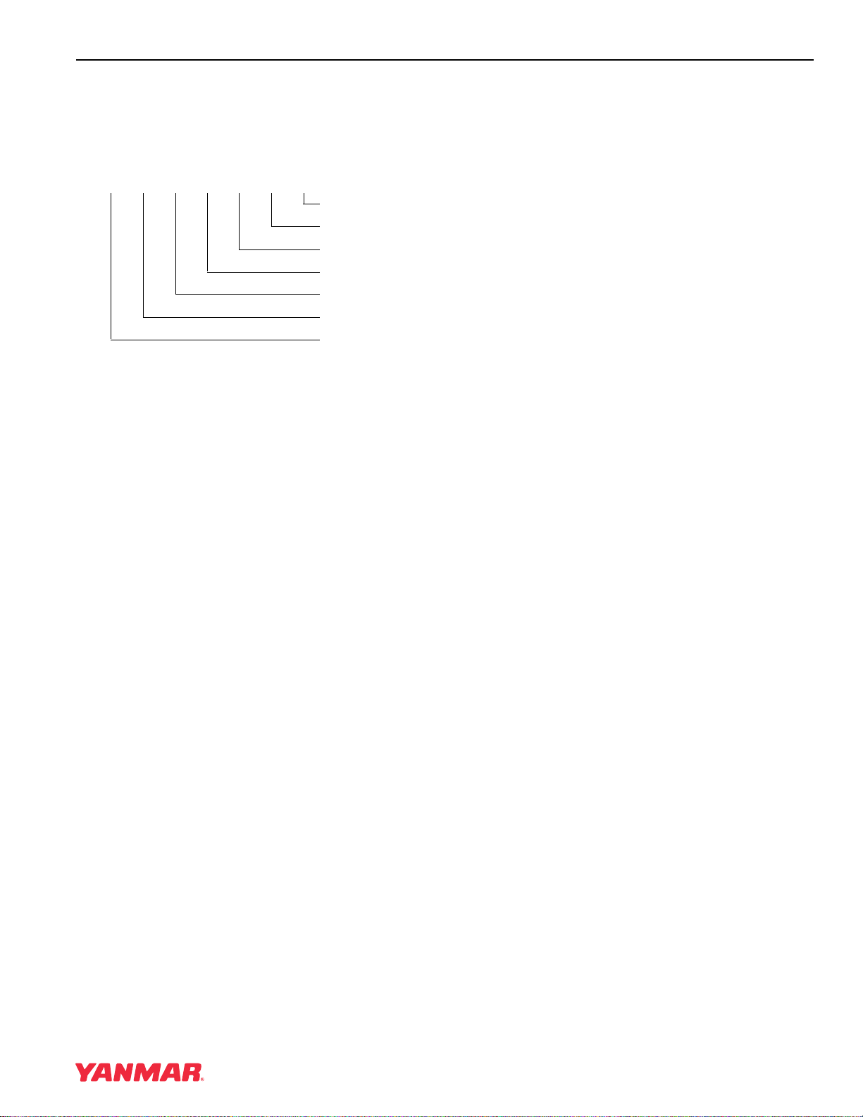
EMISSION CONTROL LABELS
Since emission control regulations are being issued
on a global basis, it is necessary to identify which
regulations a particular engine complies with. We
have listed several different types of labels you
might find on your engine.
EPA / ARB Labels
" "
(EPA) Less Than 50 HP SAE (37kW)
(EPA & ARB)
THE 97/68/EC DIRECTIVE CERTIFIED ENGINES
The engines described in this manual have been
certified by the 97/68/EC Directive.
To identify the engines that meet this certification,
the 97/68/EC emission control label is affixed on
the engines.
97/68/EC DIRECTIVE
(97/68/EC)
4-4 TNE Service Manual
Page 33
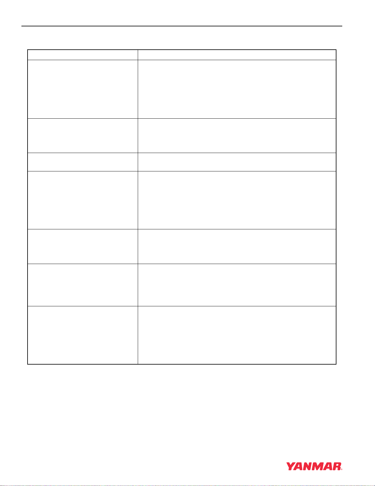
ENGINE FAMILY
The EPA / ARB labels and the 97/68/EC label all
have an Engine Family field. The following is an
explanation of the Engine Family designation:
3YDXL1.33M 3 N
Method of air aspiration
Number of cylinders
Engine speed specifications
Displacement (liter)
Non-road / Off-road engine
Yanmar Diesel
*2003 Model Year
3*: 2003
4 : 2004
5 : 2005
GENERAL SERVICE INFORMATION
TNE Service Manual
4-5
Page 34
GENERAL SERVICE INFORMATION
FUNCTION OF MAJOR ENGINE COMPONENTS
Components Functions
Air Cleaner The air cleaner prevents airborne contaminants from entering the
engine. Since the air cleaner is application specific, it must be
carefully selected by an application engineer. It is not part of the
basic engine package as shipped from the Yanmar factory.
Periodic replacement of the air cleaner filter element is necessary.
See the Periodic Maintenance Schedule on page 5-17 for the
replacement frequency.
Alternator The alternator is driven by a V-belt which is powered by the
crankshaft V-pulley. The alternator supplies electricity to the
engine systems and charges the battery while the engine is
running.
Dipstick (Engine Oil) The engine oil dipstick is used to determine the amount of engine
oil in the crankcase.
Electric Fuel Pump The electric fuel pump makes sure there is a constant supply of
diesel fuel to the fuel injection pump. The electric fuel pump is
electro-magnetic and runs on 12 VDC. An electric fuel pump may
be installed as an option or as standard equipment. Standard
equipment may vary based on engine model and specification. If
an electric fuel pump is installed, turn the key switch to the ON
position for 10 to 15 seconds to prime the fuel system.
Engine Oil Filter The engine oil filter removes contaminants and sediments from
the engine oil. Periodic replacement of the engine oil filter is
necessary. See the Periodic Maintenance Schedule on page 5-17
for the replacement frequency.
Fuel Filter The fuel filter removes contaminants and sediments from the
diesel fuel. Periodic replacement of the fuel filter is necessary. See
the Periodic Maintenance Schedule on page 5-17 for the
replacement frequency. Please note that the word “diesel” is
implied throughout this manual when the word “fuel” is used.
Fuel Filter / Water Separator The fuel filter / water separator removes contaminants, sediments
and water from diesel fuel going to the fuel filter. This is a required
component of the fuel system. This is standard equipment with
every engine. The separator is installed between the fuel tank and
the fuel pump. Periodically drain the water from the fuel filter /
water separator using the drain cock at the bottom of the
separator.
4-6 TNE Service Manual
Page 35
GENERAL SERVICE INFORMATION
Components Functions
Fuel Priming Lever If the unit has a mechanical fuel pump, a fuel priming lever on the
mechanical fuel pump primes the fuel system. The fuel system
needs to be primed before you start the engine for the first time, if
you run out of fuel, or if fuel system service is performed. To prime
the fuel system, operate the fuel priming lever until the cup in the
fuel filter is full of fuel.
Fuel Tank The fuel tank is a reservoir that holds diesel fuel. When fuel leaves
the fuel tank it goes to the fuel filter / water separator. Next, fuel is
pumped to the fuel filter by the fuel pump. Next the fuel goes to the
fuel injection pump. Since fuel is used to keep the fuel injection
pump cool and lubricated, more fuel than necessary enters the
injection pump. When the injection pump pressure reaches a
preset value, a relief valve allows excess fuel to be returned back
to the fuel tank. The fuel tank is a required engine component.
Mechanical Fuel Pump The mechanical fuel pump is a diaphragm type of pump and is
installed on the fuel injection pump body. The mechanical fuel
pump is driven by a cam on the camshaft of the fuel injection
pump. An electric fuel pump is available as an option. The
mechanical fuel pump is not installed on the fuel injection pump if
the electric fuel pump option is installed.
Side and Top Filler Port (Engine Oil) You can fill the crankcase with engine oil from either the side or
top filler port depending upon which one is most convenient.
Starter Motor The starter motor is powered by the battery. When you turn the
key switch in the operator’s console to the START position, the
starter motor engages with the ring gear installed on the flywheel
and starts the flywheel in motion.
TNE Service Manual
4-7
Page 36
GENERAL SERVICE INFORMATION
FUNCTION OF COOLING SYSTEM COMPONENTS
Components Functions
The TNE engine is liquid-cooled by means of a cooling system.
The cooling system consists of a radiator, radiator cap, engine
cooling fan, engine coolant pump, thermostat, and reserve tank.
Note that all cooling system components are required for
Cooling System
• Engine Cooling Fan The engine cooling fan is driven by a V-belt which is powered by
• Engine Coolant Pump The engine coolant pump circulates the engine coolant through
• Radiator The radiator acts as a heat exchanger. As the engine coolant
• Radiator Cap The radiator cap controls the cooling system pressure. The
proper engine operation. Since some of the components are
application specific, they must be carefully selected by an
application engineer. The application specific items are not
part of the basic engine package as shipped from the Yanmar
factory.
the crankshaft V-pulley. The purpose of the engine cooling fan is
to circulate air through the radiator.
the cylinder block and cylinder head and returns the engine
coolant to the radiator.
circulates through the cylinder block it absorbs heat. The heat in
the engine coolant is dissipated in the radiator. As the engine
cooling fan circulates air through the radiator, the heat is
transferred to the air.
cooling system is pressurized to raise the boiling point of the
engine coolant. As the engine coolant temperature rises, the
system pressure and the coolant volume increases. When the
pressure reaches a preset value, the release valve in the radiator
cap opens and the excess engine coolant flows into the reserve
tank. As the engine coolant temperature is reduced, the system
pressure and volume is reduced and the vacuum valve in the
radiator cap opens allowing engine coolant to flow from the
reserve tank back into the radiator.
• Reserve Tank The reserve tank contains the overflow of engine coolant from the
radiator. If you need to add engine coolant to the system, add it to
the reserve tank, not the radiator.
• Thermostat A thermostat is placed in the cooling system to prevent engine
coolant from circulating into the radiator until the engine coolant
temperature reaches a preset temperature. When the engine is
cold, no engine coolant flows through the radiator. Once the
engine reaches its operating temperature the thermostat opens.
By letting the engine warm up as quickly as possible, the
thermostat reduces engine wear, deposits and emissions.
4-8 TNE Service Manual
Page 37
GENERAL SERVICE INFORMATION
DIESEL FUEL
Diesel Fuel Specifications
Diesel fuel should comply with the following
specifications. The table lists several worldwide
specifications for diesel fuels.
Diesel Fuel
Specification
No. 2-D, No. 1-D, ASTM
D975-94
EN590:96 European Union
ISO 8217 DMX International
BS 2869-A1 or A2 United Kingdom
JIS K2204 Grade No.2 Japan
KSM-2610 Korea
GB252 China
Additional Technical Fuel Requirements
• The fuel cetane number should be equal to 45 or
higher.
• The sulfur content must not exceed 0.5% by
volume. Less than 0.05% is preferred.
• Bio-Diesel fuels. See Bio-Diesel Fuels on
page 4-9.
• NEVER mix kerosene, used engine oil, or
residual fuels with the diesel fuel.
• Water and sediment in the fuel should not exceed
0.05% by volume.
• Keep the fuel tank and fuel-handling equipment
clean at all times.
Location
USA
• Carbon residue content not to exceed 0.35% by
volume. Less than 0.1% is preferred.
• Total aromatics content should not exceed 35%
by volume. Less than 30% is preferred.
• PAH (polycyclic aromatic hydrocarbons) content
should be below 10% by volume.
• Metal content of Na, Mg, Si, and Al should be
equal to or lower than 1 mass ppm. (Test analysis
method JPI-5S-44-95)
• Lubricity: Wear mark of WS1.4 should be Max.
0.018 in (460
µm) at HFRR test.
Bio-Diesel Fuels
In Europe and in the United States, as well as some
other countries, non-mineral oil based fuel
resources such as RME (Rapeseed Methyl Ester)
and SOME (Soybean Methyl Ester), collectively
known as FAME (Fatty Acid Methyl Esters), are
being used as extenders for mineral oil derived
diesel fuels.
Yanmar approves the use of bio-diesel fuels that do
not exceed a blend of 5% (by volume) of FAME with
95% (by volume) of approved mineral oil derived
diesel fuel. Such bio-diesel fuels are known in the
marketplace as B5 diesel fuels.
These B5 diesel fuels must meet certain
requirements.
1. The bio-fuels must meet the minimum
specifications for the country in which they are
used.
• In Europe, bio-diesel fuels must comply with
the European Standard EN14214.
• Poor quality fuel can reduce engine performance
and / or cause engine damage.
• Fuel additives are not recommended. Some fuel
additives may cause poor engine performance.
Consult your Yanmar representative for more
information.
• Ash content not to exceed 0.01% by volume.
TNE Service Manual
• In the United States, bio-diesel fuels must
comply with the American Standard ASTM
D-6751.
2. Bio-fuels should be purchased only from
recognized and authorized diesel fuel suppliers.
Precautions and concerns regarding the use of
bio-fuels:
1. Free methanol in FAME may result in corrosion
of aluminum and zinc FIE components.
4-9
Page 38
GENERAL SERVICE INFORMATION
2. Free water in FAME may result in plugging of
fuel filters and increased bacterial growth.
3. High viscosity at low temperatures may result in
fuel delivery problems, injection pump seizures,
and poor injection nozzle spray atomization.
4. FAME may have adverse effects on some
elastomers (seal materials) and may result in
fuel leakage and dilution of the engine
lubricating oil.
5. Even bio-diesel fuels that comply with a suitable
standard as delivered, will require additional
care and attention to maintain the quality of the
fuel in the equipment or other fuel tanks. It is
important to maintain a supply of clean, fresh
fuel. Regular flushing of the fuel system, and /
or fuel storage containers, may be necessary.
6. The use of bio-diesel fuels that do not comply
with the standards as agreed to by the diesel
engine manufacturers and the diesel fuel
injection equipment manufacturers, or
bio-diesel fuels that have degraded as per the
precautions and concerns above, may affect
the warranty coverage of your engine. See
Yanmar Co., Ltd. Limited Emission
Control System Warranty - USA Only on
page 2-5.
Filling The Fuel Tank
A DANGER
FIRE AND EXPLOSION HAZARD!
• Diesel fuel is extremely flammable and
explosive under certain conditions.
• Only fill fuel tank with diesel fuel.
Filling fuel tank with gasoline may
result in a fire.
• NEVER refuel with engine running.
• Wipe up all spills immediately.
• Keep sparks, open flames or any other
form of ignition (match, cigarette,
static electric source) away when
fueling / refueling.
• NEVER overfill the fuel tank.
• Fill fuel tank and store fuel in a
well-ventilated area only.
• Failure to comply will result in death or
serious injury.
0000005en
4-10 TNE Service Manual
Page 39
GENERAL SERVICE INFORMATION
A DANGER
FIRE AND EXPLOSION HAZARD!
• Diesel fuel is extremely flammable and
explosive under certain conditions.
• Be sure to place the diesel fuel
container on the ground when
transferring diesel fuel from the pump
to the container. Hold the hose nozzle
firmly against the side of the container
while filling it. This prevents static
electricity build-up which could cause
sparks and ignite fuel vapors.
• NEVER place diesel fuel or other
flammable material such as oil, hay or
dried grass close to the engine during
engine operation or shortly after shut
down.
A DANGER
FIRE AND EXPLOSION HAZARD!
• Diesel fuel is extremely flammable and
explosive under certain conditions.
• Before you operate the engine, check
for fuel leaks. Replace rubberized fuel
hoses every two years or every 2000
hours of engine operation, whichever
comes first, even if the engine has
been out of service. Rubberized fuel
lines tend to dry out and become
brittle after two years or 2000 hours of
engine operation, whichever comes
first.
• Failure to comply will result in death or
serious injury.
0000015en
• Failure to comply will result in death or
serious injury.
0000014en
CAUTION
• Only use diesel fuels recommended by
Yanmar for the best engine
performance, to prevent engine
damage and to comply with EPA / ARB
warranty requirements.
• Only use clean diesel fuel.
• NEVER remove primary strainer from
the fuel tank filler port (if equipped). If
removed, dirt and debris could get into
the fuel system causing it to clog.
0000004en
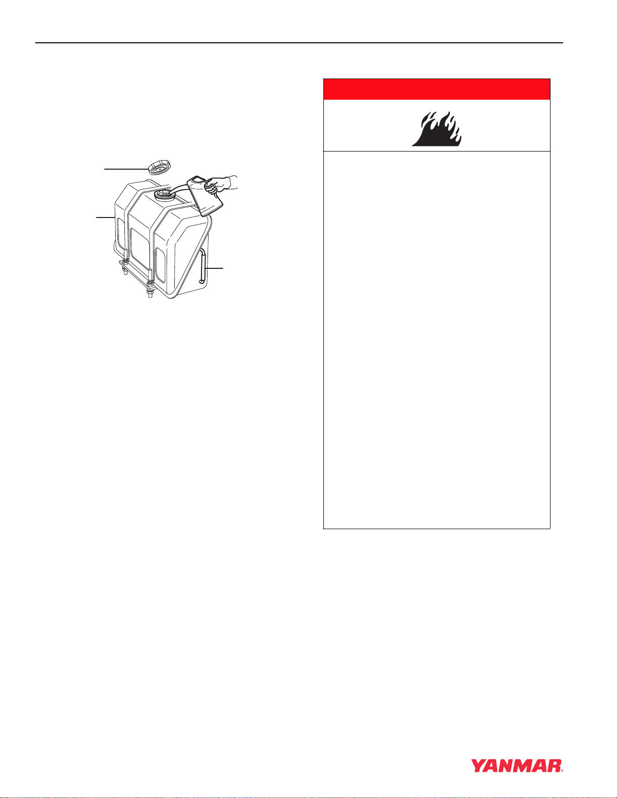
Note that a typical fuel tank is shown. The fuel tank
on your equipment may be different.
1. Clean the area around the fuel cap
(Figure 4-2, (1)).
2. Remove the fuel cap (Figure 4-2, (1)) from the
fuel tank (Figure 4-2, (2)).
TNE Service Manual
4-11
Page 40
GENERAL SERVICE INFORMATION
3. Observe the fuel level sight gauge
(Figure 4-2, (3)) and stop fueling when gauge
shows fuel tank is full. NEVER overfill the fuel
tank.
4. Replace the fuel cap (Figure 4-2, (1)) and hand
tighten. Over-tightening the fuel cap will
damage it.
(1)
(2)
(3)
0000002A
Figure 4-3
Priming the Fuel System
A DANGER
FIRE AND EXPLOSION HAZARD!
• Diesel fuel is extremely flammable and
explosive under certain conditions.
• Place an approved container under the
air bleed port when you prime the fuel
system. Never use a shop rag to catch
the fuel. Wipe up any spills
immediately. ALWAYS close the air
bleed port after you complete priming
the system.
• Wear eye protection. The fuel system
is under pressure and fuel could spray
out when you open the air bleed port.
• If the unit has an electric fuel pump,
turn the key switch to the ON position
for 10 to 15 seconds, or until the fuel
coming out of the air bleed port is free
of bubbles, to allow the electric fuel
pump to prime the system.
• If the unit has a mechanical fuel pump,
operate the fuel priming pump several
times until the fuel coming out of the
air bleed port is free of bubbles.
• Failure to comply will result in death or
serious injury.
0000006en
4-12 TNE Service Manual
Page 41
CAUTION
GENERAL SERVICE INFORMATION
6. NEVER use the starter motor to crank the
engine in order to prime the fuel system. This
may cause the starter motor to overheat and
damage the coils, pinion and / or ring gear.
To prime the fuel system on engines not equipped
with an electric fuel system:
Be environmentally responsible. Follow
these procedures for hazardous waste
disposal. Failure to follow these
procedures may seriously harm the
environment.
• Follow the guidelines of the EPA or
other governmental agency for the
proper disposal of hazardous
materials such as engine oil, diesel
fuel and engine coolant. Consult the
local authorities or reclamation facility.
• NEVER dispose of hazardous
materials irresponsibly by dumping
them into a sewer, on the ground or
into ground water or waterways.
0000013en
The fuel system needs to be primed under certain
conditions.
• Before starting the engine for the first time.
• After running out of fuel and fuel has been added
to the fuel tank.
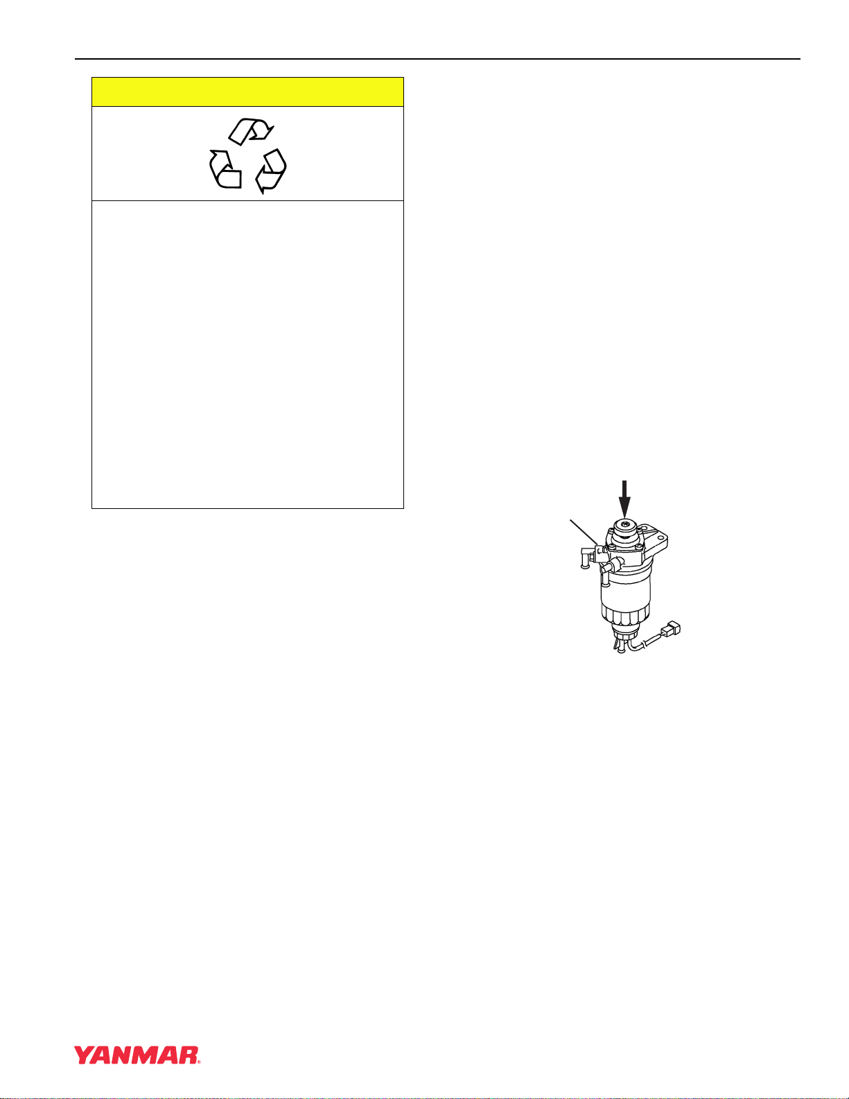
1. Place an approved container under the air
bleed port.
2. Loosen the air bleed port (Figure 4-4, (1)) 2 or
3 turns.
3. Operate the fuel priming pump (Figure 4-4, (2))
until the fuel coming out of the air bleed port is
free of bubbles.
4. Tighten the air bleed port.
5. Wipe up any spills and properly dispose of fuel.
6. NEVER use the starter motor to crank the
engine in order to prime the fuel system. This
may cause the starter motor to overheat and
damage the coils, pinion and / or ring gear.
(2)
(1)
• After fuel system maintenance such as changing
the fuel filter and draining the fuel filter / water
separator, or replacing a fuel system component.
To prime the fuel system on engines equipped with
an electric fuel pump:
1. Place an approved container under the air
bleed port.
2. Loosen the air bleed port 2 or 3 turns.
3. Turn the key to the ON position for 10 to 15
seconds or until the fuel coming out of the air
bleed port is free of bubbles.
4. Tighten the air bleed port.
5. Wipe up any spills and properly dispose of fuel.
0000862B
Figure 4-4
TNE Service Manual
4-13
Page 42
GENERAL SERVICE INFORMATION
ENGINE OIL
CAUTION
• Only use the engine oil specified.
Other engine oils may affect warranty
coverage, cause internal engine
components to seize, or shorten
engine life.
• Prevent dirt and debris from
contaminating engine oil. Carefully
clean the oil cap / dipstick and the
surrounding area before you remove
the cap.
• NEVER mix different types of engine
oil. This may adversely affect the
lubricating properties of the engine oil.
• NEVER overfill. Overfilling may result
in white exhaust smoke, engine
overspeed or internal damage.
0000005en
2. Change the engine oil after the first 50 hours
of operation and then at every 250 hours
thereafter.
3. Select the oil viscosity based on the ambient
temperature where the engine is being
operated. See the SAE Service Grade
Viscosity Chart (Figure 4-5).
4. Yanmar does not recommend the use of
engine oil “additives.”
Additional Technical Engine oil Requirements:
The engine oil must be changed when the Total
Base Number (TBN) has been reduced to 2.0. TBN
(mgKOH/g) test method; JIS K-201-5.2-2 (HCI),
ASTM D4739 (HCI).
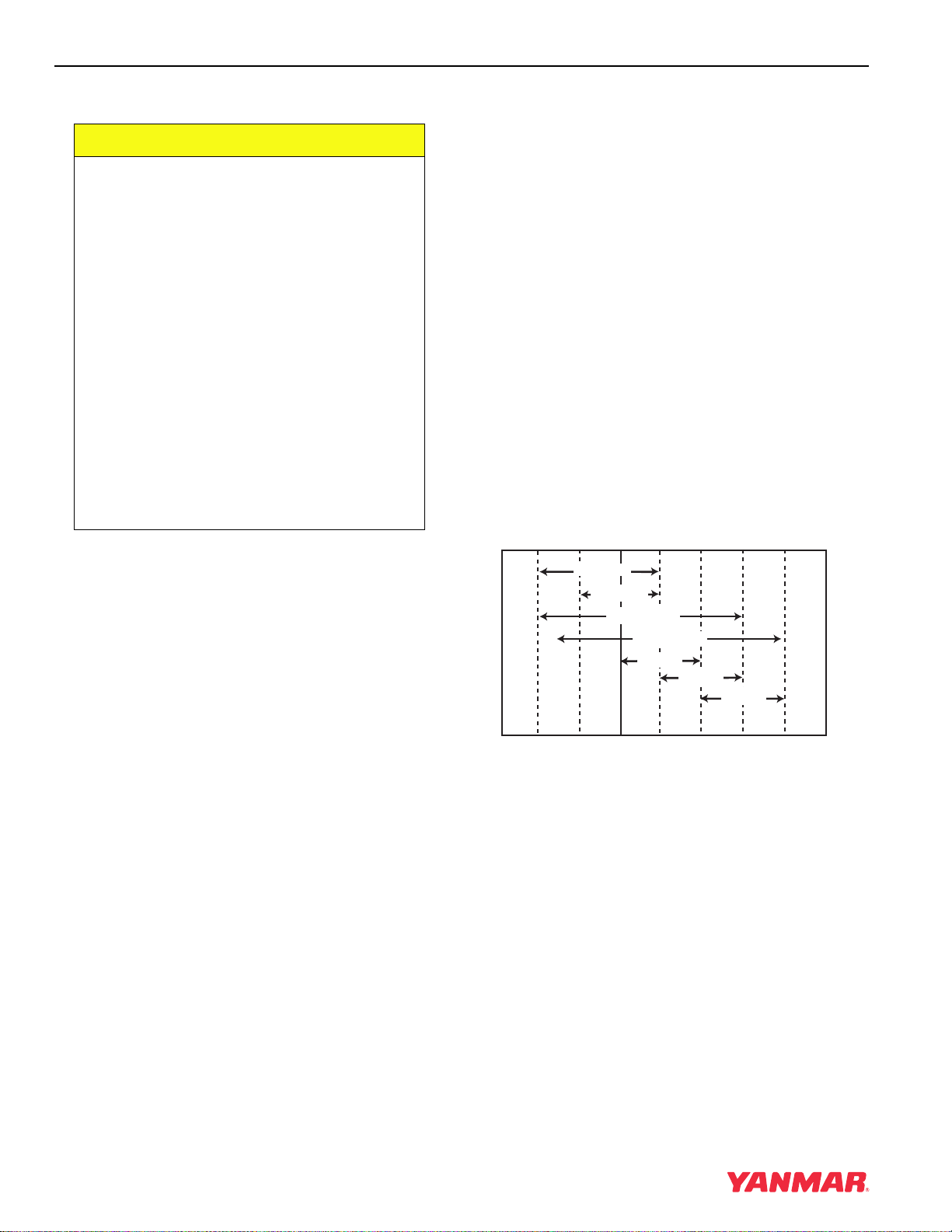
Engine Oil Viscosity
Select the appropriate engine oil viscosity based on
the ambient temperature and use the SAE Service
Grade Viscosity Chart in Figure 4-5.
Engine Oil Specifications
Use an engine oil that meets or exceeds the
following guidelines and classifications:
Service Categories
• API Service Categories CD or higher
• ACEA Service Categories E-3, E-4, and E-5
• JASO Service Category DH-1
Definitions
• API Classification (American Petroleum Institute)
• ACEA Classification (Association des
Constructeurs Européens d'Automobilies)
• JASO (Japanese Automobile Standards
Organization)
Note:
1. Be sure the engine oil, engine oil storage
containers, and engine oil filling equipment
are free of sediments and water.
SAE 10W
SAE 20W
SAE 10W-30
SAE 15W-40
SAE 20
SAE 30
SAE 40
-4˚F 14˚F 32˚F 50˚F 68˚F 86˚F 104˚F
(-20˚C) (-10˚C) (0˚C) (10˚C) (20˚C) (30˚C) (40˚C)
0000005
Figure 4-5
4-14 TNE Service Manual
Page 43
GENERAL SERVICE INFORMATION
Checking Engine Oil
1. Make sure engine is level.
2. Remove dipstick (Figure 4-6, (1)) and wipe with
clean cloth.
3. Fully reinsert dipstick.
4. Remove dipstick. The oil level should be
between upper (Figure 4-6, (2)) and lower
(Figure 4-6, (3)) lines on the dipstick.
5. Fully reinsert dipstick.
(4)
(5)
(1)
(2)
(3)
Engine Oil Capacity (Typical)
Note: These are the engine oil capacities
associated with a “Deep Standard” oil
pan. Oil capacity will vary dependant
upon which optional oil pan is used.
Refer to the operation manual provided
by the driven machine manufacturer for
the actual engine oil capacity of your
machine.
The following are typical engine oil capacities for
4TNE92-NMH, 4TNE92-NMHA, and 4TNE98-NMH
engines.
Engine Model
4TNE92-NMH
4TNE92-NMHA
4TNE98-NMH
Dipstick Upper
Limit / Lower Limit
9.7 / 7.6 qt
(9.2 / 7.2 L)
(4)
(5)
0001108A
Figure 4-6
Adding Engine Oil
1. Make sure engine is level.
2. Remove oil cap (Figure 4-6, (4)).
3. Add indicated amount of engine oil at the top or
side engine oil filler port (Figure 4-6, (5)).
4. Wait three minutes and check oil level.
5. Add more oil if necessary.
6. Replace oil cap (Figure 4-6, (4)) and hand
tighten. Over-tightening may damage the cap.
TNE Service Manual
4-15
Page 44
GENERAL SERVICE INFORMATION
ENGINE COOLANT
A DANGER
SCALD HAZARD!
• NEVER remove the radiator cap if the
engine is hot. Steam and hot engine
coolant will spurt out and seriously
burn you. Allow the engine to cool
down before you attempt to remove
the radiator cap.
• Securely tighten the radiator cap after
you check the radiator. Steam can
spurt out during engine operation if
the cap is loose.
• ALWAYS check the level of engine
coolant by observing the reserve tank.
• Failure to comply will result in death or
serious injury.
A WARNING
0000002en
A CAUTION
COOLANT HAZARD!
• Wear eye protection and rubber gloves
when you handle Long Life or
Extended Life engine coolant. If
contact with the eyes or skin should
occur, wash immediately with clean
water.
• Failure to comply may result in minor
or moderate injury.
0000005en
CAUTION
• Only use the engine coolant specified.
Other engine coolants may affect
warranty coverage, cause an internal
build up of rust and scale and / or
shorten engine life.
• Prevent dirt and debris from
contaminating engine coolant.
Carefully clean the radiator cap and
the surrounding area before you
remove the cap.
• NEVER mix different types of engine
coolants. This may adversely affect the
properties of the engine coolant.
BURN HAZARD!
• Wait until the engine cools before you
drain the engine coolant. Hot engine
coolant may splash and burn you.
• Failure to comply could result in death
or serious injury.
0000016en
Engine Coolant Specifications
Use a Long Life Coolant (LLC) or an Extended Life
Coolant (ELC) that meets or exceeds the following
guidelines and specifications.
Alternative Engine Coolant
If an Extended or Long Life Coolant is not available,
alternatively, you may use an ethylene glycol or
propylene glycol based conventional coolant
(green).
4-16 TNE Service Manual
0000006en
Page 45
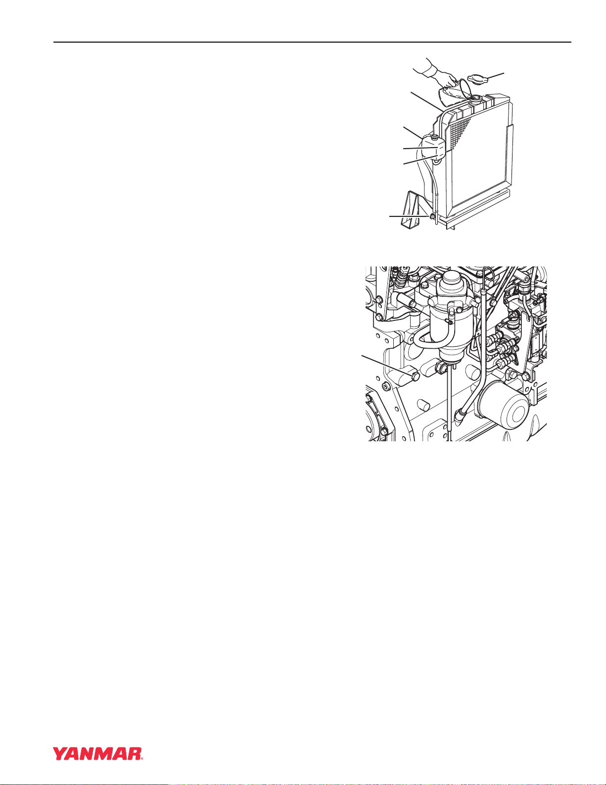
Notes:
1. ALWAYS use a mix of coolant and water.
NEVER use water only.
2. Mix coolant and water per the mixing
instructions on the coolant container.
3. Water quality is important to coolant
performance. Yanmar recommends that soft,
distilled, or demineralized water be used to
mix with coolants.
4. NEVER mix extended or long life coolants
and conventional (green) coolants.
5. NEVER mix different types and / or colors of
extended life coolants.
6. Replace the coolant every 1000 engine hours
or once a year.
Additional Technical Coolant Specifications:
• ASTM D6210, D4985 (US)
GENERAL SERVICE INFORMATION
(2)
(5)
(3)
(6)
(4)
(1)
FULL
LOW
Figure 4-7
0000029A
• JIS K-2234 (Japan)
• SAE J814C, J1941, J1034 or J2036
(International)
Filling Radiator With Engine Coolant
Fill the radiator and reserve tank as follows. This
procedure is for filling the radiator for the first time
or refilling it after it is flushed. Note that a typical
radiator is illustrated.
1. Check to be sure the radiator drain plug is
installed and tightened or the drain cock
(Figure 4-7, (1)) is closed. Also make sure the
cylinder block drain plug (Figure 4-8, (1)) is
installed and tightened.
(1)
0001578A
Figure 4-8
2. Remove the radiator cap (Figure 4-7, (2)) by
turning it counter-clockwise about 1/3 of a turn.
TNE Service Manual
4-17
Page 46
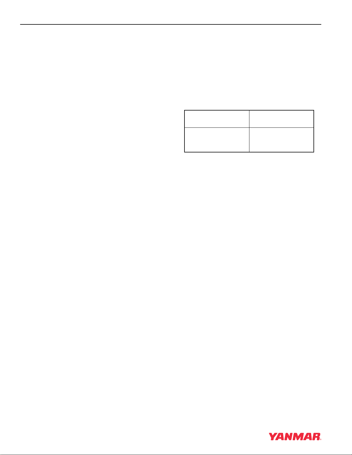
GENERAL SERVICE INFORMATION
3. Pour the engine coolant slowly into the radiator
until it is even with the lip of the engine coolant
filler port. Make sure that air bubbles do not
develop as you fill the radiator.
4. Reinstall the radiator cap (Figure 4-7, (2)).
Align the tabs on the back side of the radiator
cap with the notches on the engine coolant filler
port. Press down and turn the cap clockwise
about 1/3 of a turn.
5. Remove the cap of the reserve tank
(Figure 4-7, (3)), and fill it to the LOW (COLD)
mark (Figure 4-7, (4)) with engine coolant.
Reinstall the cap.
6. Check the hose (Figure 4-7, (5)) that connects
the reserve tank (Figure 4-7, (3)) to the
radiator. Be sure it is securely connected and
there are no cracks or damage. If the hose is
damaged, engine coolant will leak out instead
of going into the reserve tank.
7. Run the engine until it is at operating
temperature. Check the level of engine coolant
in the reserve tank. When the engine is running
and the engine coolant is at normal
temperature, the coolant level in the tank should
be at the FULL (HOT) mark (Figure 4-7, (6)). If
the engine coolant is not at the FULL (HOT)
mark, add additional engine coolant to the
reserve tank to bring the level to the FULL
(HOT) mark.
Engine Coolant Capacity (Typical)
Note: Capacities listed are for the engine only
without a radiator. Refer to the operation
manual provided by the driven machine
manufacturer for the total cooling system
capacity of your specific machine.
The following are typical engine coolant capacities
for 4TNE92-NMH, 4TNE92-NMHA, and
4TNE98-NMH engines.
Engine Model
4TNE92-NMH
4TNE92-NMHA
4TNE98-NMH
Engine Coolant
Capacity
1.11 gal. (4.2 L)
4-18 TNE Service Manual
Page 47
GENERAL SERVICE INFORMATION
SPECIFICATIONS
Description of Model Number
4TNE92-OO
Customer / Machine Code
Cylinder Bore (in terms of mm)
Yanmar Diesel Engine Series
Number of Cylinders (4)
Engine Speed Specifications
NOTATION AVAILABLE ENGINE SPEED INTENDED USES
-1
VM 2000 ~ 2500 rpm (min
VM: Variable Medium Speed
Engine General Specifications
Type Vertical Inline, Water Cooled, 4-Cycle Diesel Engine
Combustion System Indirect Injection
Starting System Electric Starting
Cooling System Radiator
Lubricating System Forced Lubrication With Trochoid Pump
PTO Position Flywheel End
Direction of Rotation Counterclockwise Viewed from Flywheel Side
) Agricultural, Constructive, Industrial Machines
Notes:
1. The information described in Principal Engine Specifications is for a “standard” engine. To obtain the
information for the engine installed in your driven machine, please refer to the manual provided by the
driven machine manufacturer.
2. Engine rating conditions are as follows (SAE J1349, ISO 3046/1):
• Atmospheric Condition: Room temperature 77°F (25°C), Atmospheric pressure 29.53 in Hg (100 kPa,
750 mm Hg), Relative humidity 30%
• Fuel Temperature at Fuel Injector Pump Inlet: 104°F (40°C)
• With Cooling Fan, Air Cleaner, Muffler: Yanmar Standard
• After Engine Break-In Period. Output Allowable Deviation: ± 3%
• 1 PS = 0.7355 kW
• 1 hp SAE (Society of Automotive Engineers)= 0.7457 kW
TNE Service Manual
4-19
Page 48
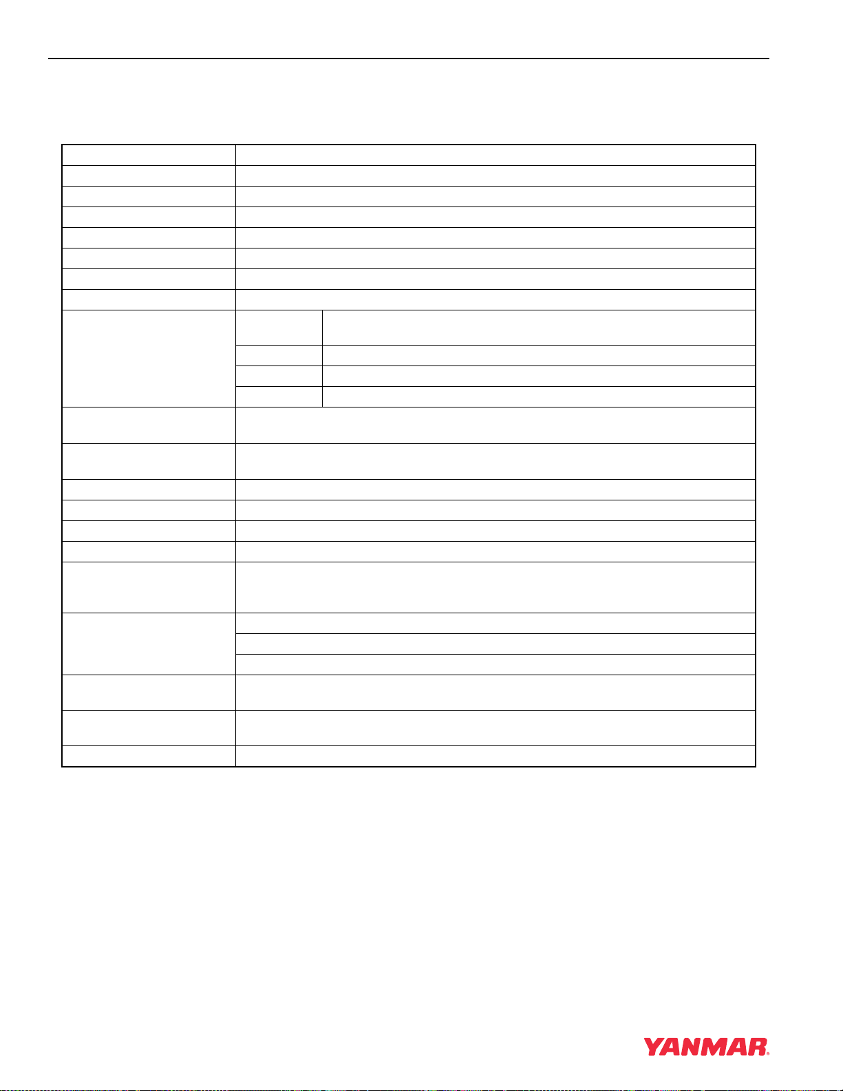
GENERAL SERVICE INFORMATION
PRINCIPAL ENGINE SPECIFICATIONS
4TNE92-NMH
Engine Model 4TNE92-NMH
Version VM
Type Vertical Inline Diesel Engine
Combustion System Indirect Injection
Aspiration Natural
No. of Cylinders 4
Bore × Stroke 3.62 x 3.94 in (92
Displacement 162.3 cu in (2.659 L)
Max. Rated Output (Net) rpm
High Idle Speed
(Bare Engine)
Low Idle Speed
(Bare Engine)
Engine Weight (Dry)* 491.6 lb (194 kg)
PTO Position Flywheel Side
Direction of Rotation Counterclockwise Viewed From Flywheel Side
Cooling System Liquid-Cooled With Radiator
Lubricating System Forced Lubrication With Trochoid Pump
Starting System Electric Starting - Starter Motor: DC12V, 3.1 hp (2.3 kW)
Dimensions (L × W × H)* 24.9 x 19.6 x 28.0 in
Engine Oil Pan Capacity 9.7 / 7.6 qt (9.2 / 7.2 L)
Engine Coolant Capacity 1.11 gal (4.2 L) Engine Only
-1
)
(min
hp SAE 45.1
kW 33.6
PS 45.7
2725 ± 25 rpm
850 ± 25 rpm
At normal operating speeds, oil pressure is: 42 - 57 psi (0.29 - 0.39 MPa; 3.0 - 4.0 kgf/cm
At idle, oil pressure is: No less than 8.5 psi (0.06 MPa; 0.6 kgf/cm2)
Alternator: DC12V, 60A
Recommended Battery Capacity: 12V, 622 CCA (Cold Cranking Amps)
(632 x 498 x 711 mm)
(Dipstick Upper Limit / Lower Limit)
× 100 mm)
2450
2
)
* Engine specifications do not include height of
lifting eyes nor dimensions or specifications for the
Cooling Fan, Radiator, Muffler, and Air Cleaner.
4-20 TNE Service Manual
Page 49
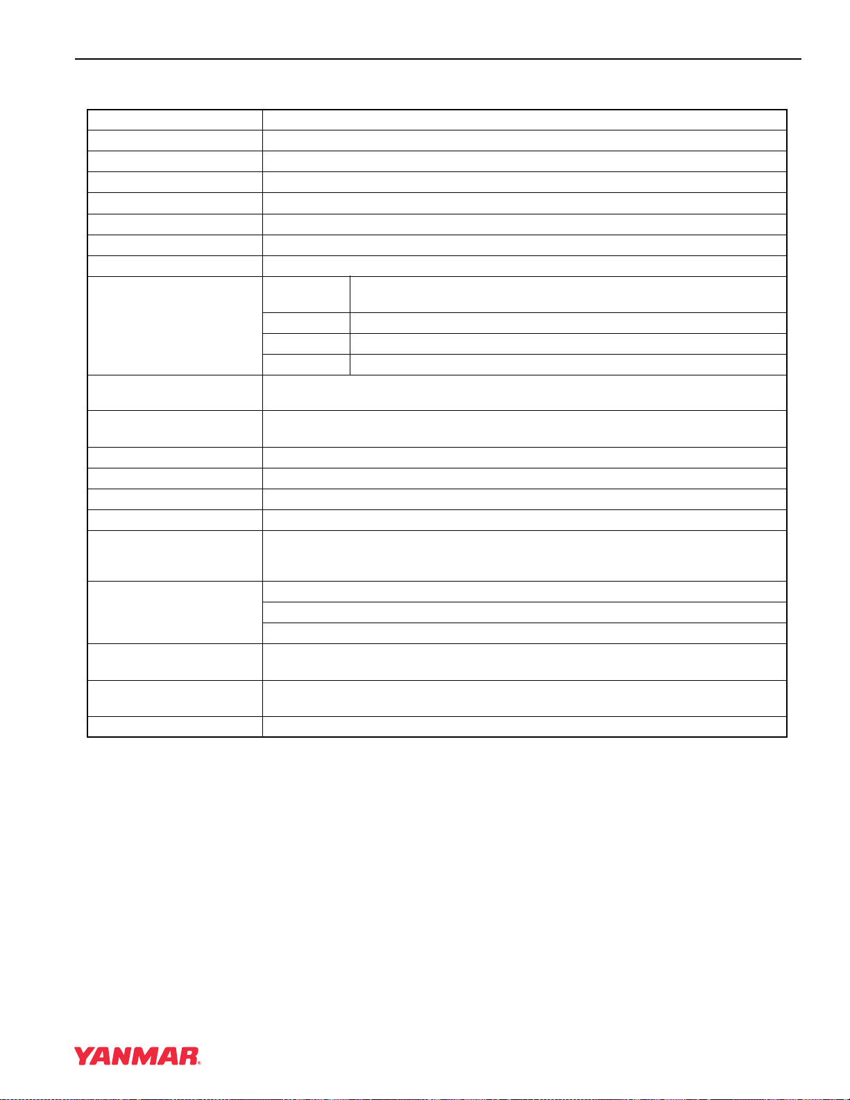
GENERAL SERVICE INFORMATION
4TNE92-NMHA
Engine Model 4TNE92-NMHA
Version VM
Type Vertical Inline Diesel Engine
Combustion System Indirect Injection
Aspiration Natural
No. of Cylinders 4
Bore × Stroke 3.62 x 3.94 in (92
Displacement 162.3 cu in (2.659 L)
Max. Rated Output (Net) rpm
High Idle Speed
(Bare Engine)
Low Idle Speed
(Bare Engine)
Engine Weight (Dry)* 491.6 lb (194 kg)
PTO Position Flywheel Side
Direction of Rotation Counterclockwise Viewed From Flywheel Side
Cooling System Liquid-Cooled With Radiator
Lubricating System Forced Lubrication With Trochoid Pump
Starting System Electric Starting - Starter Motor: DC12V, 3.1 hp (2.3 kW)
Dimensions (L × W × H)* 24.9 x 19.6 x 26.6 in
Engine Oil Pan Capacity 9.7 / 7.6 qt (9.2 / 7.2 L)
Engine Coolant Capacity 1.11 gal (4.2 L) Engine Only
-1
)
(min
hp SAE 39.0
kW 29.1
PS 39.6
2450 ± 25 rpm
850 ± 25 rpm
At normal operating speeds, oil pressure is: 42 - 57 psi (0.29 - 0.39 MPa; 3.0 - 4.0 kgf/cm
At idle, oil pressure is: No less than 8.5 psi (0.06 MPa; 0.6 kgf/cm2)
Alternator: DC12V, 60A
Recommended Battery Capacity: 12V, 622 CCA (Cold Cranking Amps)
(632 x 498 x 676 mm)
(Dipstick Upper Limit / Lower Limit)
× 100 mm)
2050
2
)
* Engine Specifications Without Cooling Fan,
Radiator, Muffler, and Air Cleaner.
TNE Service Manual
4-21
Page 50
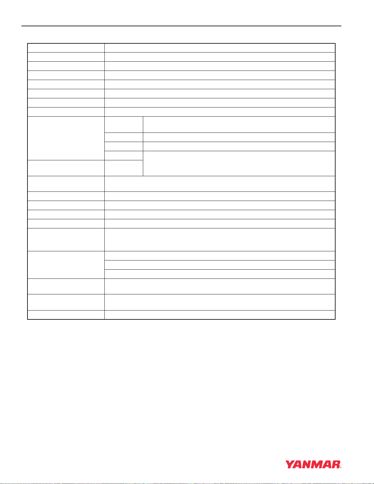
GENERAL SERVICE INFORMATION
4TNE98-NMH
Engine Model 4TNE98-NMH
Version VM
Type Vertical Inline Diesel Engine
Combustion System Indirect Injection
Aspiration Natural
No. of Cylinders 4
Bore × Stroke 3.86 x 4.33 in (98
Displacement 202.5 cu in (3.319 L)
Max. Rated Output (Net) rpm
(min
-1
)
hp SAE 63.6
kW 47.4
PS
High Idle Speed
(Bare Engine)
Low Idle Speed
(Bare Engine)
2725 ± 25
rpm
850 ± 25 rpm
Engine Weight (Dry)* 491.6 lb (194 kg)
PTO Position Flywheel Side
Direction of Rotation Counterclockwise Viewed From Flywheel Side
Cooling System Liquid-Cooled With Radiator
Lubricating System Forced Lubrication With Trochoid Pump
At normal operating speeds, oil pressure is: 42 - 57 psi (0.29 - 0.39 MPa; 3.0 - 4.0 kgf/cm
At idle, oil pressure is: No less than 8.5 psi (0.06 MPa; 0.6 kgf/cm
Starting System Electric Starting - Starter Motor: DC12V, 3.1 hp (2.3 kW)
Alternator: DC12V, 60A
Recommended Battery Capacity: 12V, 622 CCA (Cold Cranking Amps)
Dimensions (L × W × H)* 24.9 x 19.6 x 28.0 in
(632 x 498 x 711 mm)
Engine Oil Pan Capacity 9.7 / 7.6 qt (9.2 / 7.2 L)
(Dipstick Upper Limit / Lower Limit)
Engine Coolant Capacity 1.11 gal (4.2 L) Engine Only
× 110 mm)
2400
64.4
2
2
)
)
* Engine Specifications Without Cooling Fan,
Radiator, Muffler, and Air Cleaner.
4-22 TNE Service Manual
Page 51

ENGINE SERVICE INFORMATION
Engine Tuning
Inspection Item Standard Limit
Intake / Exhaust Valve Gap
Fuel Injection Pressure
Fuel Injection Timing with Plunger Lifted 0.039 in
(1 mm)
Compression Pressure at 250 rpm (250 min¯¹)
Max. (when cold) 86 psi (0.59 MPa,
Lubricating Oil Pressure
Thermostat
At rated output 42 - 57 psi (0.29 - 0.39 MPa,
When idling 8.5 psi (0.06 MPa,
GENERAL SERVICE INFORMATION
0.006 - 0.010 in
(0.15 - 0.25 mm)
1711 - 1842 psi
(11.8 - 12.7 MPa
120 - 130 kgf / cm²)
6°±1°ATDC -
425 - 428 psi
(2.93 - 2.95 MPa
29 - 31 kgf / cm²)
2
6.0 kgf/cm
2.96 - 3.98 kgf/cm
0.6 kgf/cm
Valve Opening Temperature
160°F
(71°C)
)
2
) or greater
2
)
Full Opening Lift
0.32 in (8 mm) or
-
-
341 psi
(2.35 MPa
24 kgf / cm²)
-
-
-
Temperature
Above
185°F (85°C)
TNE Service Manual
4-23
Page 52

GENERAL SERVICE INFORMATION
TIGHTENING TORQUES FOR STANDARD BOLTS AND NUTS
Item
Hexagon Bolt (7T)
and Nut
PT PLug
Pipe Joint Bolt
Nominal Thread
Diameter
M6 x 1.0 mm
M8 x 1.25 mm
M10 x 1.5 mm
M12 x 1.75 mm
M14 x 1.5 mm
M16 x 1.5 mm
1/8 mm
1/4 mm
3/8 mm
1/2 mm
M8
M10
M12
M14
M16
x Pitch Tightening Torque Remarks
7 to 9 ft lbs
(87 to 104 in lbs,
9.8 to 11.8 N·m,
1.0 to 1.2 kgf·m)
17 to 21 ft lbs
(200 to 251 in lbs,
22.6 to 28.4 N·m,
2.3 to 2.9 kgf·m)
33 to 40 ft lbs
(44.1 to 53.9 N·m,
4.5 to 5.5 kgf·m)
58 to 72 ft lbs
(78.4 to 98.0 N·m,
8.0 to 10 kgf·m)
94 to 108 ft lbs
(127.5 to 147.1 N·m,
13 to 15 kgf·m)
159 to 174 ft lbs
(215.7 235.4 N·m,
22 to 24 kgf·m)
7 ft lbs
(87 in lbs, 9.8 N·m, 1.0 kgf·m)
14 ft lbs
(173 in lbs, 19.6 N·m, 2.0
kgf·m)
22 ft lbs
(29.4 N·m, 3.0 kgf·m)
43 ft lbs
(58.8 N·m, 6.0 kgf·m)
9 to 12 ft lbs
(112 to 148 in lbs,
12.7 to 16.7 N·m,
1.3 to 1.7 kgf·m)
14 to 19 ft lbs
(173 to 225 in lbs,
19.6 to 18.734 N·m,
2.0 to 3.5 kgf·m)
18 to 25 ft lbs
(24.5 to 34.3 N·m,
2.5 to 3.5 kgf·m)
29 to 36 ft lbs
(39.2 to 49.0 N·m,
4.0 to 5.0 kgf·m)
36 to 43 ft lbs
(49.0 to 58.8 N·m,
5.0 to 6.0 kgf·m)
Use 80% of the value at left
when the tightening part is
aluminum.
Use 60% of the value at left
for 4T bolts and lock nuts.
-
-
Note: Lubricating oil is not applied to threaded portion and seat surface.
4-24 TNE Service Manual
Page 53

GENERAL SERVICE INFORMATION
STANDARD TORQUE CHART
Thread size × Pitch mm M6×1.0 M8×1.25 M10×1.5 M12×1.75 M14×1.5 M16×1.5
in lbs96.0 ± 9.0-----
Tightening Torque
ft lbs - 19.0 ± 2.0 36.0 ± 4.0 65.0 ± 7.0 101.0 ± 7.0 167.0 ± 7.0
N·m 10.8 ± 1.0 25.5 ± 2.9 49.0 ± 4.9 88.3 ± 9.8 137 ± 9.8 22.6 ± 9.8
kgf·m 1.1 ± 0.1 2.6 ± 0.3 5.0 ± 0.5 9.0 ± 1.0 14.0 ± 1.5 23.0 ± 2.0
TNE Service Manual
4-25
Page 54

GENERAL SERVICE INFORMATION
ABBREVIATIONS AND SYMBOLS
Abbreviations
A ampere
AC alternating current
ACEA Association des Constructeurs
Européens d’Automobilies
Ah ampere-hour
approx. approximately
API American Petroleum Institute
ARB Air Resources Board
ATDC after top dead center
BTDC before top dead center
°C degree Celsius
CARB California Air Resources Board
CCA cold cranking amp
cm centimeter
cm³ cubic centimeter
cm³/min cubic centimeter per minute
cu in cubic inch
DC direct current
DI direct injection
DVA direct volt adapter
EPA Environmental Protection Agency
ESG electronic speed governor
°F degree Fahrenheit
fl oz fluid ounce (U.S.)
fl oz/min fluid ounce (U.S.) per minute
ft foot
ft lb foot pound
ft lbf/min foot pound force per minute
g gram
gal/hr gallon (U.S.) per hour
gal gallon (U.S.)
GL gear lubricant
hp horsepower (U.S.)
hrs hours
I.D. inside diameter
IDI indirect injection
in inch
in lb inch pound
JASO Japanese Automobile Standards
Organization
kg kilogram
kgf/cm² kilogram force per square
centimeter
kgf·m kilogram force meter
km kilometers
kPa kilopascal
kW kilowatt
L liter
L/hr liter per hour
lb pound
lbf pond force
mL milliliter
mm millimeter
MPa megapascal
mV millivolt
N newton
N·m newton meter
No. number
O.D. outside diameter
oz ounce
PS horsepower (metric)
psi pound per square inch
qt quart (U.S.)
RPM revolutions per minute
SAE Society of Automotive Engineers
sec. second
t short ton 2000lb
TBN Total Base Number
TDC top dead center
V volt
VAC volt alternating current
VDC volt direct current
W watt
Symbols
° angular degree
+ plus
- minus
± plus or minus
Ω ohm
µ micro
% percent
~ approximate
4-26 TNE Service Manual
Page 55

GENERAL SERVICE INFORMATION
UNIT CONVERSIONS
Unit Prefixes
Prefix Symbol Power
mega M x 1,000,000
kilo k x 1,000
centi c x 0.01
milli m x 0.001
micro µ x 0.000001
Units of Length
mile x 1.6090 = km
ft x 0.3050 = m
in x 2.5400 = cm
in x 25.4000 = mm
km x 0.6210 = mile
m x 3.2810 = ft
cm x 0.3940 = in
mm x 0.0394 = in
Units of Volume
gal (U.S.) x 3.78540 = L
qt (U.S.) x 0.94635 = L
cu in x 0.01639 = L
cu in x 16.38700 = mL
fl oz (U.S.) x 0.02957 = L
fl oz (U.S.) x 29.57000 = mL
cm³ x 1.00000 = mL
cm³ x 0.03382 = fl oz (U.S.)
Units of Mass
lb x 0.45360 = kg
oz x 28.35000 = g
kg x 2.20500 = lb
g x 0.03527 = oz
Units of Force
lbf x 4.4480 = N
lbf x 0.4536 = kgf
N x 0.2248 = lbf
N x 0.1020 = kgf
kgf x 2.2050 = lbf
kgf x 9.8070 = N
Units of Torque
ft lb x 1.3558 = N·m
ft lb x 0.1383 = kgm
in lb x 0.1130 = N-m
in lb x 0.0115 = kgm
kgm x 7.2330 = ft lb
kgm x 86.8000 = in lb
kgm x 9.8070 = N·m
N·m x 0.7376 = ft lb
N·m x 8.8510 = in lb
N·m x 0.1020 = kgm
Units of Pressure
psi x 0.0689 = bar
psi x 6.8950 = kPa
psi x 0.0703 = kg/cm²
bar x 14.5030 = psi
bar x 100.0000 = kPa
bar x 29.5300 = in Hg
(60°F)
kPa x 0.1450 = psi
kPa x 0.0100 = bar
kPa x 0.0102 = kg/cm²
kg/cm² x 98.0700 = psi
kg/cm² x 0.9807 = bar
kg/cm² x 14.2200 = kPa
in Hg (60°) x 0.0333 = bar
in Hg (60°) x 3.3770 = kPa
in Hg (60°) x 0.0344 = kg/cm²
Units of Power
hp (metric or
PS)
hp (metric or
PS)
hp SAE x 1.0138697 = hp (metric
hp SAE x 0.7456999 = kW
kW x 1.3596216 = hp (metric
kW x 1.3410221 = hp SAE
x 0.9863201 = hp SAE
x 0.7354988 = kW
or PS)
or PS)
Units of Temperature
°F = (1.8 · °C) + 32
°C = 0.556 · (°F - 32)
TNE Service Manual
4-27
Page 56

GENERAL SERVICE INFORMATION
This Page Intentionally Left Blank
4-28 TNE Service Manual
Page 57

MAINTENANCE
TNE Service Manual
Precautions ................................................................................... 5-16
The Importance of Periodic Maintenance................................ 5-16
Performing Periodic Maintenance ........................................... 5-16
Yanmar Replacement Parts .................................................... 5-16
Required EPA / ARB Maintenance - USA Only....................... 5-16
EPA / ARB Installation Requirements - USA Only .................. 5-16
Tightening Fasteners............................................................... 5-16
Standard Torque Chart.................................................................. 5-17
Section 5
PERIODIC
Table of Contents
Page
Periodic Maintenance Schedule.................................................... 5-17
Periodic Maintenance Procedures ................................................ 5-19
Daily......................................................................................... 5-19
Every 250 Hours of Operation................................................. 5-21
Every 500 Hours of Operation................................................. 5-26
Every 1000 Hours of Operation............................................... 5-29
Every 2000 Hours of Operation............................................... 5-34
Every 4000 Hours of Operation............................................... 5-35
TNE Service Manual
5-1
Page 58

PERIODIC MAINTENANCE
This Page Intentionally Left Blank
5-2 TNE Service Manual
Page 59

This section of the Service Manual describes the
procedures for proper care and maintenance of the
engine.
CAUTION
NEVER permit anyone to operate the
engine or driven machine without proper
training.
• Read and understand this Operation
Manual before you operate the
machine to ensure that you follow safe
operating practices and maintenance
procedures.
• Machine safety signs and labels are
additional reminders for safe operating
and maintenance techniques.
• See your authorized Yanmar industrial
engine dealer or distributor for
additional training.
0000002en
PERIODIC MAINTENANCE
A DANGER
EXPLOSION HAZARD!
• NEVER check the remaining battery
charge by shorting out the terminals.
This will result in a spark and may
cause an explosion or fire. Use a
hydrometer to check the remaining
battery charge.
• If the electrolyte is frozen, slowly warm
the battery before you recharge it.
• Failure to comply will result in death or
serious injury.
0000007en
A DANGER
FIRE AND EXPLOSION HAZARD!
• Only use the key switch to start the
engine.
• NEVER jump start the engine. Sparks
caused by jumping the battery to the
starter terminals may cause a fire or
explosion.
• Failure to comply will result in death or
serious injury.
0000004en
TNE Service Manual
5-3
Page 60

PERIODIC MAINTENANCE
A DANGER
SCALD HAZARD!
• NEVER remove the radiator cap if the
engine is hot. Steam and hot engine
coolant will spurt out and seriously
burn you. Allow the engine to cool
down before you attempt to remove
the radiator cap.
• Securely tighten the radiator cap after
you check the radiator. Steam can
spurt out during engine operation if
the cap is loose.
• ALWAYS check the level of engine
coolant by observing the reserve tank.
• Failure to comply will result in death or
serious injury.
0000002en
A DANGER
FIRE AND EXPLOSION HAZARD!
• Diesel fuel is extremely flammable and
explosive under certain conditions.
• Only fill fuel tank with diesel fuel.
Filling fuel tank with gasoline may
result in a fire.
• NEVER refuel with engine running.
• Wipe up all spills immediately.
• Keep sparks, open flames or any other
form of ignition (match, cigarette,
static electric source) away when
fueling / refueling.
• NEVER overfill the fuel tank.
• Fill fuel tank and store fuel in a
well-ventilated area only.
• Failure to comply will result in death or
serious injury.
0000005en
5-4 TNE Service Manual
Page 61

PERIODIC MAINTENANCE
A DANGER
FIRE AND EXPLOSION HAZARD!
• Diesel fuel is extremely flammable and
explosive under certain conditions.
• Before you operate the engine, check
for fuel leaks. Replace rubberized fuel
hoses every two years or every 2000
hours of engine operation, whichever
comes first, even if the engine has
been out of service. Rubberized fuel
lines tend to dry out and become
brittle after two years or 2000 hours of
engine operation, whichever comes
first.
• Failure to comply will result in death or
serious injury.
0000015en
A DANGER
FIRE AND EXPLOSION HAZARD!
• Diesel fuel is extremely flammable and
explosive under certain conditions.
• Be sure to place the diesel fuel
container on the ground when
transferring diesel fuel from the pump
to the container. Hold the hose nozzle
firmly against the side of the container
while filling it. This prevents static
electricity build-up which could cause
sparks and ignite fuel vapors.
• NEVER place diesel fuel or other
flammable material such as oil, hay or
dried grass close to the engine during
engine operation or shortly after shut
down.
• Failure to comply will result in death or
serious injury.
0000014en
A DANGER
FIRE AND EXPLOSION HAZARD!
• Diesel fuel is extremely flammable and
explosive under certain conditions.
• NEVER use diesel fuel as a cleaning
agent.
• Failure to comply will result in death or
serious injury.
0000012en
TNE Service Manual
5-5
Page 62

PERIODIC MAINTENANCE
A DANGER
FIRE AND EXPLOSION HAZARD!
• Diesel fuel is extremely flammable and
explosive under certain conditions.
• NEVER remove the fuel cap with
engine running.
• Failure to comply will result in death or
serious injury.
0000011en
A DANGER
CRUSH HAZARD!
• When you need to transport an engine
for repair have a helper assist you
attach it to a hoist and load it on a
truck.
A DANGER
FIRE AND EXPLOSION HAZARD!
• Diesel fuel is extremely flammable and
explosive under certain conditions.
• When you remove any fuel system
component to perform maintenance
(such as changing the fuel filter) place
an approved container under the
opening to catch the fuel.
• NEVER use a shop rag to catch the
fuel. Vapors from the rag are extremely
flammable and explosive.
• Wipe up any spills immediately.
• Wear eye protection. The fuel system
is under pressure and fuel could spray
out when you remove any fuel system
component.
• Failure to comply will result in death or
serious injury.
0000009en
• NEVER stand under hoisted engine. If
the hoist mechanism fails, the engine
will fall on you, causing serious injury
or death.
• Failure to comply will result in death or
serious injury.
0000008en
5-6 TNE Service Manual
Page 63

PERIODIC MAINTENANCE
A DANGER
FIRE AND EXPLOSION HAZARD!
• Diesel fuel is extremely flammable and
explosive under certain conditions.
• Place an approved container under the
air bleed port when you prime the fuel
system. Never use a shop rag to catch
the fuel. Wipe up any spills
immediately. ALWAYS close the air
bleed port after you complete priming
the system.
• Wear eye protection. The fuel system
is under pressure and fuel could spray
out when you open the air bleed port.
• If the unit has an electric fuel pump,
turn the key switch to the ON position
for 10 to 15 seconds, or until the fuel
coming out of the air bleed port is free
of bubbles, to allow the electric fuel
pump to prime the system.
• If the unit has a mechanical fuel pump,
operate the fuel priming pump several
times until the fuel coming out of the
air bleed port is free of bubbles.
A WARNING
EXHAUST HAZARD!
• NEVER operate the engine in an
enclosed area such as a garage,
tunnel, underground room, manhole or
ship’s hold without proper ventilation.
• NEVER block windows, vents, or other
means of ventilation if the engine is
operating in an enclosed area. All
internal combustion engines create
carbon monoxide gas during
operation. Accumulation of this gas
within an enclosure could cause
illness or even death.
• Make sure that all connections are
tightened to specifications after repair
is made to the exhaust system.
• Failure to comply could result in death
or serious injury.
0000003en
• Failure to comply will result in death or
serious injury.
0000006en
TNE Service Manual
5-7
Page 64

PERIODIC MAINTENANCE
A WARNING
SEVER HAZARD!
• Keep hands and other body parts
away from moving / rotating parts
such as the cooling fan, flywheel or
PTO shaft.
• Wear tight fitting clothing and keep
your hair short or tie it back while the
engine is running.
• Remove all jewelry before you operate
or service the machine.
• NEVER start the engine in gear.
Sudden movement of the engine
and / or machine could cause death or
serious personal injury.
• NEVER operate the engine without the
guards in place.
A WARNING
BURN HAZARD!
• Keep your hands, and other body
parts, away from hot engine surfaces
such as the muffler, exhaust pipe,
turbocharger (if equipped) and engine
block during operation and shortly
after you shut the engine down. These
surfaces are extremely hot while the
engine is operating and could
seriously burn you.
• Failure to comply could result in death
or serious injury.
0000015en
A WARNING
• Before you start the engine make sure
that all bystanders are clear of the
area.
• Keep children and pets away while the
engine is operating.
• Check before starting the engine that
any tools or shop rags used during
maintenance have been removed from
the area.
• Failure to comply could result in death
or serious injury.
0000002en
ALCOHOL AND DRUG HAZARD!
• NEVER operate the engine while you
are
under the influence of alcohol or
drugs.
• NEVER operate the engine when you
are feeling ill.
• Failure to comply could result in death
or serious injury.
0000004en
5-8 TNE Service Manual
Page 65

PERIODIC MAINTENANCE
A WARNING
EXPOSURE HAZARD!
• Wear personal protective equipment
such as gloves, work shoes, eye and
hearing protection as required by the
task at hand.
• NEVER wear jewelry, unbuttoned
cuffs, ties or loose fitting clothing
when you are working near
moving / rotating parts such as the
cooling fan, flywheel or PTO shaft.
• ALWAYS tie long hair back when you
are working near moving / rotating
parts such as a cooling fan, flywheel,
or PTO shaft.
• NEVER operate the engine while
wearing a headset to listen to music or
radio because it will be difficult to hear
warning signals.
A WARNING
BURN HAZARD!
• Batteries contain sulfuric acid. NEVER
allow battery fluid to come in contact
with clothing, skin or eyes. Severe
burns could result. ALWAYS wear
safety goggles and protective clothing
when servicing the battery. If contact
with the skin and / or eyes should
occur, flush with a large amount of
water and obtain prompt medical
treatment.
• Failure to comply could result in death
or serious injury.
0000007en
A WARNING
• Failure to comply could result in death
or serious injury.
0000005en
HIGH PRESSURE HAZARD!
• Avoid skin contact with high pressure
diesel fuel spray caused by a fuel
system leak such as a broken fuel
injection line. High pressure fuel can
penetrate your skin and result in
serious injury. If you are exposed to
high pressure fuel spray obtain
prompt medical treatment.
• NEVER check for a fuel leak with your
hands. ALWAYS use a piece of wood
or cardboard.
• Failure to comply could result in death
or serious injury.
0000018en
TNE Service Manual
5-9
Page 66

PERIODIC MAINTENANCE
A WARNING
SHOCK HAZARD!
• Turn off the battery switch (if
equipped) or disconnect the negative
battery cable before servicing the
electrical system.
• Check the electrical harnesses for
cracks, abrasions, and damaged or
corroded connectors. ALWAYS keep
the connectors and terminals clean.
• Failure to comply could result in death
or serious injury.
0000009en
A WARNING
A WARNING
BURN HAZARD!
• If you must drain the engine oil while it
is still hot, stay clear of the hot engine
oil to avoid being scalded. Make sure
you wear eye protection.
• Failure to comply could result in death
or serious injury.
0000011en
A CAUTION
SEVER HAZARD!
• Stop the engine before you begin to
service it.
• NEVER leave the key in the key switch
when you are servicing the engine.
Someone may accidentally start the
engine and not realize you are
servicing it. This could result in a
serious injury.
• If you must service the engine while it
is operating, remove all jewelry, tie
back long hair, and keep your hands,
other body parts and clothing away
from moving / rotating parts.
• Failure to comply could result in death
or serious injury.
0000010en
FLYING OBJECT HAZARD!
• ALWAYS wear eye protection when
servicing engine and when using
compressed air or high-pressure
water. Dust, flying debris, compressed
air, pressurized water or steam may
injure your eyes.
• Failure to comply may result in minor
or moderate injury.
0000003en
5-10 TNE Service Manual
Page 67

PERIODIC MAINTENANCE
CAUTION
• Only use diesel fuels recommended by
Yanmar for the best engine
performance, to prevent engine
damage and to comply with EPA / ARB
warranty requirements.
• Only use clean diesel fuel.
• NEVER remove primary strainer from
the fuel tank filler port (if equipped). If
removed, dirt and debris could get into
the fuel system causing it to clog.
0000004en
CAUTION
• Only use the engine oil specified.
Other engine oils may affect warranty
coverage, cause internal engine
components to seize, or shorten
engine life.
• Prevent dirt and debris from
contaminating engine oil. Carefully
clean the oil cap / dipstick and the
surrounding area before you remove
the cap.
• NEVER mix different types of engine
oil. This may adversely affect the
lubricating properties of the engine oil.
• NEVER overfill. Overfilling may result
in white exhaust smoke, engine
overspeed or internal damage.
0000005en
CAUTION
• Only use the engine coolant specified.
Other engine coolants may affect
warranty coverage, cause an internal
build up of rust and scale and / or
shorten engine life.
• Prevent dirt and debris from
contaminating engine coolant.
Carefully clean the radiator cap and
the surrounding area before you
remove the cap.
• NEVER mix different types of engine
coolants. This may adversely affect the
properties of the engine coolant.
0000006en
CAUTION
• NEVER attempt to modify the engine’s
design or safety features such as
defeating the engine speed limit
control or the diesel fuel injection
quantity control.
• Modifications may impair the engine’s
safety and performance
characteristics and shorten the
engine’s life. Any alterations to this
engine may void its warranty. Be sure
to use Yanmar genuine replacement
parts.
0000079en
TNE Service Manual
5-11
Page 68

PERIODIC MAINTENANCE
CAUTION
Observe the following environmental
operating conditions to maintain engine
performance and avoid premature
engine wear:
• Avoid operating in extremely dusty
conditions.
• Avoid operating in the presence of
chemical gases or fumes.
• Avoid operating in a corrosive
atmosphere such as salt water spray.
• NEVER install the engine in a
floodplain unless proper precautions
are taken to avoid being subject to a
flood.
• NEVER expose the engine to the rain.
0000003enTNE
CAUTION
Observe the following environmental
operating conditions to maintain engine
performance and avoid premature
engine wear:
• NEVER run the engine if the ambient
temperature is above +113°F (+45°C)
or below +5°F (-15°C).
◆ If the ambient temperature exceeds
+113°F (+45°C) the engine may
overheat and cause the engine oil to
break down.
◆ If the ambient temperature falls
below +5°F (-15°C) rubber
components such as gaskets and
seals will harden causing premature
engine wear and damage.
◆ Contact your authorized Yanmar
industrial engine dealer or
distributor if the engine will be
operated in either temperature
extreme.
• Contact your authorized Yanmar
industrial engine dealer or distributor
if you need to operate the engine at
high altitudes. At high altitudes the
engine will lose power, run rough, and
produce exhaust gases that exceed
the design specifications.
0000065en
CAUTION
NEVER hold the key in the START
position for longer than 15 seconds or
the starter motor will overheat.
0000007en
5-12 TNE Service Manual
Page 69

PERIODIC MAINTENANCE
CAUTION
For maximum engine life, Yanmar
recommends that when shutting the
engine down, you allow the engine to
idle, without load, for 5 minutes. This
will allow the engine components that
operate at high temperatures, such as
the turbocharger (if equipped) and
exhaust system, to cool slightly before
the engine itself is shut down.
0000008en
CAUTION
NEVER use an engine starting aid such
as ether. Engine damage will result.
0000009en
CAUTION
Make sure the engine is installed on a
level surface. If a continuously running
engine is installed at an angle greater
than 20° (in any direction) or if an engine
runs for short periods of time (less than
3 minutes) at an angle greater than 25°
in any direction, engine oil may enter the
combustion chamber causing exessive
engine speed and generate white
smoke. This may cause serious engine
damage.
0000010enTNE
CAUTION
New Engine Break In:
• On the initial engine start-up, allow the
engine to idle for approximately 15
minutes while you check for proper
engine oil pressure, diesel fuel leaks,
engine oil leaks, coolant leaks, and for
proper operation of the indicators
and / or gauges.
• During the first hour of operation, vary
the engine speed and load on the
engine. Short periods of maximum
engine speed and load are desirable.
Avoid prolonged operation at
minimum or maximum engine speeds
and loads for the next 4 to 5 hours.
• During the break-in period, carefully
observe the engine oil pressure and
engine temperature.
• During the break-in period, check the
engine oil and coolant levels
frequently.
0000011en
CAUTION
NEVER engage the starter motor while
the engine is running. This may damage
the starter motor pinion and / or ring
gear.
0000012en
TNE Service Manual
5-13
Page 70

PERIODIC MAINTENANCE
CAUTION
Be environmentally responsible. Follow
these procedures for hazardous waste
disposal. Failure to follow these
procedures may seriously harm the
environment.
• Follow the guidelines of the EPA or
other governmental agency for the
proper disposal of hazardous
materials such as engine oil, diesel
fuel and engine coolant. Consult the
local authorities or reclamation facility.
• NEVER dispose of hazardous
materials irresponsibly by dumping
them into a sewer, on the ground or
into ground water or waterways.
0000013en
CAUTION
Protect the air cleaner, turbocharger (if
equipped) and electric components
from damage when you use steam or
use high-pressure water to clean the
engine.
0000014en
CAUTION
NEVER use high pressure water or
compressed air at greater than 28 psi or
a wire brush to clean the radiator fins.
Radiator fins damage easily.
0000016en
CAUTION
NEVER attempt to adjust the low or high
idle speed limit screw. This may impair
the safety and performance of the
machine and shorten its life. If the idle
speed limit screws require adjustment,
see your authorized Yanmar industrial
engine dealer or distributor.
0000017en
CAUTION
If the fuel filter / water separator is
positioned higher than the fuel level in
the fuel tank, water may not drip out
when the fuel filter / water separator
drain cock is opened. If this happens,
turn the air vent screw on the top of the
fuel filter / water separator 2-3 turns
counterclockwise.
Be sure to tighten the air vent screw
after the water has drained out.
0000025en
CAUTION
• NEVER overfill the engine with engine
oil.
• ALWAYS keep the oil level between
upper and lower lines on the dipstick.
0000015en
5-14 TNE Service Manual
• When the engine is operated in dusty
conditions, clean the air cleaner
element more frequently.
• NEVER operate the engine with the air
cleaner or element(s) removed. This
may cause foreign material to enter the
engine and damage it.
CAUTION
0000026en
Page 71

CAUTION
The maximum air intake restriction shall
be 0.90 psi (6.23 kPa; 635 mm Aq) or
less. Clean or replace the air cleaner
element if the air intake restriction
exceeds the above mentioned value.
0000046en
PERIODIC MAINTENANCE
TNE Service Manual
5-15
Page 72

PERIODIC MAINTENANCE
PRECAUTIONS
The Importance of Periodic Maintenance
Engine deterioration and wear occurs in proportion
to length of time the engine has been in service and
the conditions the engine is subject to during
operation. Periodic maintenance prevents
unexpected downtime, reduces the number of
accidents due to poor machine performance and
helps extend the life of the engine.
Performing Periodic Maintenance
A WARNING
EXHAUST HAZARD!
• NEVER operate the engine in an
enclosed area such as a garage,
tunnel, underground room, manhole or
ship’s hold without proper ventilation.
• NEVER block windows, vents, or other
means of ventilation if the engine is
operating in an enclosed area. All
internal combustion engines create
carbon monoxide gas during
operation. Accumulation of this gas
within an enclosure could cause
illness or even death.
• Make sure that all connections are
tightened to specifications after repair
is made to the exhaust system.
• Failure to comply could result in death
or serious injury.
0000003en
Perform periodic maintenance procedures in an
open, level area free from traffic. If possible,
perform the procedures indoors to prevent
environmental conditions, such as rain, wind, or
snow, from damaging the machine.
Yanmar Replacement Parts
Yanmar recommends that you use genuine Yanmar
parts when replacement parts are needed.
Genuine replacement parts help ensure long
engine life.
Required EPA / ARB Maintenance USA Only
To maintain optimum engine performance and
compliance with the Environmental Protection
Agency (EPA) Regulations Non-road Engines and
the California Air Resources Board (ARB,
California), it is essential that you follow the
Periodic Maintenance Schedule on page 5-17 and
Periodic Maintenance Procedures which start on
page 5-19.
EPA / ARB Installation Requirements
- USA Only
The following are the installation requirements for
the EPA / ARB. Unless these requirements are met,
the exhaust gas emissions will not be within the
limits specified by the EPA and ARB.
Maximum Exhaust Gas Restriction - 3.84 psi
(26.48 kPa; 2700 mm Aq) or less.
Maximum Air Intake Restriction - 0.90 psi
(6.23kPa; 635mm Aq) or less. Clean or replace the
air cleaner element if the air intake restriction
exceeds the above mentioned value.
Tightening Fasteners
Use the correct amount of torque when you tighten
fasteners on the machine. Applying excessive
torque may damage the fastener or component and
not enough torque may cause a leak or component
failure.
5-16 TNE Service Manual
Page 73

PERIODIC MAINTENANCE
CAUTION
The tightening torque in the Standard
Torque Ch art (page 5-17) should be
applied only to the bolts with a “7” head.
(JIS strength classification: 7T)
• Apply 60% torque to
bolts that are not listed.
• Apply 80% torque when
tightened to aluminum alloy.
0000023enTNESM
STANDARD TORQUE CHART
Thread size × Pitch mm M6×1.0 M8×1.25 M10×1.5 M12×1.75 M14×1.5 M16×1.5
in lbs96.0 ± 9.0-----
Tightening Torque
ft lbs - 19.0 ± 2.0 36.0 ± 4.0 65.0 ± 7.0 101.0 ± 7.0 167.0 ± 7.0
N·m 10.8 ± 1.0 25.5 ± 2.9 49.0 ± 4.9 88.3 ± 9.8 137.0 ± 9.8 226.0 ± 9.8
kgf·m 1.1 ± 0.1 2.6 ± 0.3 5.0 ± 0.5 9.0 ± 1.0 14.0 ± 1.5 23.0 ± 2.0
PERIODIC MAINTENANCE SCHEDULE
Daily and periodic maintenance is important to
keep the engine in good operating condition. The
following is a summary of maintenance items by
periodic maintenance intervals. Periodic
maintenance intervals vary depending on engine
application, loads, diesel fuel and engine oil used
and are hard to establish definitively. The following
should be treated only as a general guideline.
CAUTION
Establish a periodic maintenance plan
according to the engine application and
make sure you perform the required
periodic maintenance at intervals
indicated. Failure to follow these
guidelines will impair the engine’s safety
and performance characteristics,
shorten the engine’s life and may affect
the warranty coverage on your engine.
See Yanmar Limited Warranty on
page 2-3.
Consult your authorized Yanmar
industrial engine dealer or distributor for
assistance when checking items marked
with a
z.
0000024enTNESM
TNE Service Manual
5-17
Page 74

PERIODIC MAINTENANCE
c: Check : Replace z: Contact your authorized Yanmar industrial engine dealer or distributor
System Check Item
Cooling
System
Cylinder
Head
Electrical
Equipment
Emission
Control
Warranty
Engine Oil Check Engine Oil Level
Engine
Speed
Control
Fuel Check & Re-fill Fuel Tank
Hoses Inspect or Replace Fuel
Intake &
Exhaust
1 Very dirty conditions will require daily check and cleaning.
2 In dirty or dusty environments, replace at 1000 hours or as needed.
Check & Re-fill Engine
Coolant
Check Engine Coolant
Temperature Indicator
Check & Clean Radiator
1
Fins
Check & Adjust Cooling Fan
V-belt
Drain, Flush, and Re-fill
Cooling System with New
Coolant
Adjust Intake / Exhaust
Valve Clearance
Check Battery
Check Battery Indicator
Inspect, Clean & Test Fuel
Injectors
Check Engine Oil Pressure
Indicator
Drain & Fill Engine Oil z or every
Replace Engine Oil Filter
Check & Adjust Governor
Lever & Engine Speed
Control
Level
Check Fuel Filter Indicator
Drain Fuel Filter / Water
Separator
Check Fuel Filter / Water
Separator
Clean Fuel Filter / Water
Separator
Replace Fuel Filter
System & Cooling System
Hoses
Clean or Replace Air
Cleaner Element
1
1
1 2
Check
During
Operation
Daily
c
c
First Check after 50 hours
c
c
c
c
c
c
c
c
Every
250
hours
c or every
6 weeks
c or every
6 weeks
c or every
6 weeks
c or every
6 weeks
Periodic Maintenance Interval
Every
500
hours
Every
1000
hours
z or every
6 months
3 months
z or every
3 months
c or every
3 months
c or every
6 months
or every
6 months
Every
2000
hours
z or every
1 year
or every
1 year
Every
4000
hours
or every
2 yr.
which-ever
comes first
c or every
2 years
Note: These procedures are considered normal maintenance and are performed at the owner’s expense.
5-18 TNE Service Manual
Page 75

PERIODIC MAINTENANCE
PERIODIC MAINTENANCE PROCEDURES
Daily
Perform the following procedures daily.
• Drain Fuel Filter / Water Separator
• Check Fuel Hoses and Engine Coolant Hoses
Drain Fuel Filter / Water Separator
A DANGER
FIRE AND EXPLOSION HAZARD!
• Diesel fuel is extremely flammable and
explosive under certain conditions.
• When you remove any fuel system
component to perform maintenance
(such as changing the fuel filter) place
an approved container under the
opening to catch the fuel.
• NEVER use a shop rag to catch the
fuel. Vapors from the rag are extremely
flammable and explosive.
• Wipe up any spills immediately.
• Wear eye protection. The fuel system
is under pressure and fuel could spray
out when you remove any fuel system
component.
• Failure to comply will result in death or
serious injury.
0000009en
A WARNING
HIGH PRESSURE HAZARD!
• Avoid skin contact with high pressure
diesel fuel spray caused by a fuel
system leak such as a broken fuel
injection line. High pressure fuel can
penetrate your skin and result in
serious injury. If you are exposed to
high pressure fuel spray obtain
prompt medical treatment.
• NEVER check for a fuel leak with your
hands. ALWAYS use a piece of wood
or cardboard. Have your authorized
Yanmar industrial engine dealer or
distributor repair the damage.
• Failure to comply could result in death
or serious injury.
0000008en
CAUTION
If the fuel filter / water separator is
positioned higher than the fuel level in
the fuel tank, water may not drip out
when the fuel filter / water separator
drain cock is opened. If this happens,
turn the air vent screw on the top of the
fuel filter / water separator 2-3 turns
counterclockwise.
Be sure to tighten the air vent screw
after the water has drained out.
0000025en
TNE Service Manual
5-19
Page 76

PERIODIC MAINTENANCE
CAUTION
Be environmentally responsible. Follow
these procedures for hazardous waste
disposal. Failure to follow these
procedures may seriously harm the
environment.
• Follow the guidelines of the EPA or
other governmental agency for the
proper disposal of hazardous
materials such as engine oil, diesel
fuel and engine coolant. Consult the
local authorities or reclamation facility.
• NEVER dispose of hazardous
materials irresponsibly by dumping
them into a sewer, on the ground or
into ground water or waterways.
1. Position an approved container under the fuel
filter / water separator (Figure 5-1, (1)) to
collect the contaminants.
2. Loosen the drain cock (Figure 5-1, (2)) at the
bottom of the fuel filter / water separator. Drain
any water collected inside.
3. Hand tighten the drain cock.
4. Be sure to prime the diesel fuel system when
you are done. See Priming the Fuel System on
page 4-12.
Check Fuel Hoses and Engine Coolant Hoses
Daily check the fuel system and engine coolant
system hoses. If they are cracked or degraded,
replace them.
0000013en
NEVER wait until the scheduled periodic
maintenance if the fuel filter indicator comes on.
The fuel filter / water separator contains a sensor to
detect the amount of water and contaminants. This
sensor sends a signal to an indicator to alert the
operator.
Drain the fuel filter / water separator as follows:
(1)
(2)
0000862C
Figure 5-1
5-20 TNE Service Manual
Page 77

Every 250 Hours of Operation
Perform the following maintenance every 250 hours
of operation.
• Check and Clean Radiator Fins
• Check and Adjust Cooling Fan V-Belt
• Check Battery
• Clean Air Cleaner Element
Check and Clean Radiator Fins
PERIODIC MAINTENANCE
• If there is a large amount of contamination on
the fins, apply detergent, thoroughly clean and
rinse with tap water.
CAUTION
NEVER use high pressure water or
compressed air at greater than 28 psi or
a wire brush to clean the radiator fins.
Radiator fins damage easily.
0000016en
A CAUTION
FLYING OBJECT HAZARD!
• ALWAYS wear eye protection when
servicing engine and when using
compressed air or high-pressure
water. Dust, flying debris, compressed
air, pressurized water or steam may
injure your eyes.
• Failure to comply may result in minor
or moderate injury.
0000003en
Dirt and dust adhering to the radiator fins reduce
the cooling performance, causing overheating.
Make it a rule to check the radiator fins daily and
clean as needed.
FULL
W
O
L
(1)
0000085A
Figure 5-2
Note that a typical radiator is shown in Figure 5-2
for illustrative purposes only.
• Blow off dirt and dust from fins and radiator with
2
28 psi (0.19MPa, 2kgf/cm
) or less of
compressed air (Figure 5-2, (1)). Be careful
not to damage the fins with the compressed air.
TNE Service Manual
5-21
Page 78

PERIODIC MAINTENANCE
Check and Adjust Cooling Fan V-belt
The V-belt will slip if it does not have the proper
tension. This will prevent the alternator from
generating sufficient power. Also, the engine will
overheat due to the engine coolant pump pulley
slipping. Be sure to check for proper belt tension
after the first 50 hours of operation. Thereafter,
check the belt tension every 250 hours of
operation.
Check and adjust the V-belt tension (deflection) as
follows:
1. Press the V-belt down with your thumb with a
force of approximately 22 ft lbs (98 N•m,
10 kgf•m) to check the deflection.
There are three positions to check for V-belt
tension (Figure 5-3, (A), (B) and (C)). You can
check the tension at whichever position is the
most accessible. The proper deflection of a used
V-belt at each position is:
Used V-belt Tension
ABC
3/8 ~1/2 in
(10~14 mm)
1/4 ~3/8 in
(7~10 mm)
(A)
5/16 ~1/2 in
(9~13 mm)
2. If necessary, adjust the V-belt tension. Loosen
the set bolt (Figure 5-4, (1)) and move the
alternator (Figure 5-4, (2)) with a pry bar
(Figure 5-4, (3)) to tighten the V-belt.
(3)
(1)
(2)
0001553A
Figure 5-4
3. Check the V-belt for cracks, oil or wear. If any of
these conditions exist, replace the V-belt.
• “New V-belt” refers to a V-belt which has been
used less than 5 minutes on a running engine.
• “Used V-belt” refers to a V-belt which has been
used on a running engine for 5 minutes or
more.
(B)
Figure 5-3
(C)
0001111A
4. Inspect the condition of the used V-belt. There
must be clearance (Figure 5-5, (1)) between
the V-belt and the bottom of the pulley groove. If
there is no clearance (Figure 5-5, (2)) between
the V-belt and the bottom of the pulley groove,
replace the V-belt.
(2)
(1)
0000584
Figure 5-5
5-22 TNE Service Manual
Page 79

5. Install the new V-belt. Refer to the table for
proper tension.
New V-belt Tension
ABC
5/16 ~7/16 in
(8~12 mm)
3/16 ~5/16 in
(5~8 mm)
1/4 ~7/16 in
(7~11 mm)
6. After adjusting, run the engine for 5 minutes or
more. Check the tension again using the
specifications for a used V-belt.
Used V-belt Tension
ABC
3/8 ~1/2 in
(10~14 mm)
1/4 ~3/8 in
(7~10 mm)
5/16 ~1/2 in
(9~13 mm)
Check Battery
A DANGER
PERIODIC MAINTENANCE
A WARNING
BURN HAZARD!
• Batteries contain sulfuric acid. NEVER
allow battery fluid to come in contact
with clothing, skin or eyes. Severe
burns could result. ALWAYS wear
safety goggles and protective clothing
when servicing the battery. If contact
with the skin and / or eyes should
occur, flush with a large amount of
water and obtain prompt medical
treatment.
• Failure to comply could result in death
or serious injury.
0000007en
EXPLOSION HAZARD!
• NEVER check the remaining battery
charge by shorting out the terminals.
This will result in a spark and may
cause an explosion or fire. Use a
hydrometer to check the remaining
battery charge.
• If the electrolyte is frozen, slowly warm
the battery before you recharge it.
• Failure to comply will result in death or
serious injury.
0000007en
CAUTION
Be environmentally responsible. Follow
these procedures for hazardous waste
disposal. Failure to follow these
procedures may seriously harm the
environment.
• Follow the guidelines of the EPA or
other governmental agency for the
proper disposal of hazardous
materials such as engine oil, diesel
fuel and engine coolant. Consult the
local authorities or reclamation facility.
• NEVER dispose of hazardous
materials irresponsibly by dumping
them into a sewer, on the ground or
into ground water or waterways.
0000013en
TNE Service Manual
5-23
Page 80

PERIODIC MAINTENANCE
(3)
(1)
0000067A
Figure 5-6
(2)
Clean Air Cleaner Element
Note that a typical air cleaner is shown in
Figure 5-7 and Figure 5-8 for illustrative purposes
only.
The engine performance is adversely affected
when the air cleaner element is clogged with dust.
Be sure to clean the air filter element periodically.
1. Unlatch and remove the air cleaner cover
(Figure 5-7, (1)).
2. Remove the element (Figure 5-7, (2)) (outer
element if equipped with two elements).
• When the amount of fluid nears the lower limit
(Figure 5-6, (1)), fill with distilled water
(Figure 5-6, (2)) so it is at the upper limit
(Figure 5-6, (3)). If operation continues with
insufficient battery fluid, the battery life is
shortened, and the battery may overheat and
explode. During the summer, check the fluid
level more often than specified.
• If the engine cranking speed is so slow that the
engine does not start, recharge the battery.
• If the engine still will not start after charging,
have your authorized Yanmar industrial engine
dealer or distributor check the battery and the
engine’s starting system.
• If operating the machine where the ambient
temperature could drop to 5°F (-15°C) or less,
remove the battery from the machine at the end
of the day. Store the battery in a warm place
until the next use. This will help start the engine
easily at low ambient temperatures.
A CAUTION
FLYING OBJECT HAZARD!
• ALWAYS wear eye protection when
servicing engine and when using
compressed air or high-pressure
water. Dust, flying debris, compressed
air, pressurized water or steam may
injure your eyes.
• Failure to comply may result in minor
or moderate injury.
0000003en
5-24 TNE Service Manual
Page 81

PERIODIC MAINTENANCE
3. Blow air (Figure 5-7, (3)) through the element
from the inside out using 42–71 psi
(0.29−0.49MPa, 3.0−5.0kgf/cm
2
) compressed
air to remove the particulates. Use the lowest
possible air pressure to remove the dust without
damaging the element.
If the air cleaner is equipped with a double
element, only remove and replace the inner
element (Figure 5-8, (1)) if the engine lacks
power or the dust indicator actuates (if
equipped). This is in addition to replacing the
outer element.
The inner element should not be removed when
cleaning or replacing the outer element. The
inner element is used to prevent dust from
entering the engine while servicing the outer
element.
(6)
(4)
(2)
(3)
(5)
6. Install the element into the air cleaner case
(Figure 5-7, (4)).
7. Install the air cleaner cover making sure you
match the arrow (Figure 5-7, (5)) on the cover
with the arrow on the case (Figure 5-7, (6)).
8. Latch the air cleaner cover to the case.
CAUTION
• When the engine is operated in dusty
conditions, clean the air cleaner
element more frequently.
• NEVER operate the engine with the air
cleaner or element(s) removed. This
may cause foreign material to enter the
engine and damage it.
0000026en
(1)
0000070A
Figure 5-7
(1)
0000071A
Figure 5-8
4. Replace the element with a new one if the
element is damaged, excessively dirty or oily.
5. Clean inside of the air cleaner cover.
TNE Service Manual
5-25
Page 82

PERIODIC MAINTENANCE
Every 500 Hours of Operation
Perform the following maintenance every 500 hours
of operation.
• Replace Engine Oil and Engine Oil Filter
• Check and Adjust the Governor Lever and
Engine Speed Control
Replace Engine Oil and Engine Oil Filter
A WARNING
BURN HAZARD!
• If you must drain the engine oil while it
is still hot, stay clear of the hot engine
oil to avoid being scalded. Make sure
you wear eye protection.
CAUTION
• Only use the engine oil specified.
Other engine oils may affect warranty
coverage, cause internal engine
components to seize, or shorten
engine life.
• Prevent dirt and debris from
contaminating engine oil. Carefully
clean the oil cap / dipstick and the
surrounding area before you remove
the cap.
• NEVER mix different types of engine
oil. This may adversely affect the
lubricating properties of the engine oil.
• NEVER overfill. Overfilling may result
in white exhaust smoke, engine
overspeed or internal damage.
0000005en
CAUTION
• Failure to comply could result in death
or serious injury.
0000011en
Be environmentally responsible. Follow
these procedures for hazardous waste
disposal. Failure to follow these
procedures may seriously harm the
environment.
• Follow the guidelines of the EPA or
other governmental agency for the
proper disposal of hazardous
materials such as engine oil, diesel
fuel and engine coolant. Consult the
local authorities or reclamation facility.
• NEVER dispose of hazardous
materials irresponsibly by dumping
them into a sewer, on the ground or
into ground water or waterways.
0000013en
5-26 TNE Service Manual
Page 83

PERIODIC MAINTENANCE
Change the engine oil every 500 hours of
operation. Replace the engine oil filter at the same
time.
Drain the engine oil as follows:
1. Make sure the engine is level.
2. Start the engine and bring it up to operating
temperature.
3. Stop the engine.
4. Remove the oil filler cap (Figure 5-9, (1)) to
vent the engine crankcase and to allow the
engine oil to drain more easily.
5. Position a container (Figure 5-10, (1)) under
the engine to collect waste oil.
(1)
Remove the engine oil filter as follows:
1. Turn the engine oil filter (Figure 5-11, (1))
counterclockwise (Figure 5-11, (2)) using a
filter wrench.
(2)
(1)
0001109
Figure 5-10
(1)
0001108B
Figure 5-9
6. Remove the drain plug (Figure 5-10, (2)). Allow
oil to drain.
After all oil has been drained from the engine,
install the drain plug (Figure 5-10, (2)) and
tighten to 14-17 ft lbs (19.6-23.5 N•m, 2.0-2.4
kgf•m).
7. Dispose of used oil properly.
(1)
(3)
(2)
0001110A
Figure 5-11
2. Clean the engine oil filter mounting face.
3. Lightly coat the gasket on the new oil filter with
engine oil. Install the new engine oil filter
manually by turning it clockwise
(Figure 5-11, (3)) until it contacts the mounting
surface. Tighten an additional 3/4 of a turn
using the filter wrench.
TNE Service Manual
5-27
Page 84

PERIODIC MAINTENANCE
Applicable Engine Oil Filter Part No.
(Figure 5-11, (1))
4TNE92-NMH
4TNE92-NMHA
129150-35152
4TNE98-NMH
4. Add new engine oil to the engine as specified in
Adding Engine Oil on page 4-15.
Check and Adjust the Governor Lever and Engine Speed Control
The governor lever and engine speed control
(accelerator lever, pedal, etc.) of the machine are
connected together by an accelerator cable or rod.
If the cable becomes stretched, or the connections
loosen, the governor lever may not respond to
change of engine speed control position. This may
make operation of the machine unsafe. Check the
cable periodically and adjust if necessary. Consult
your authorized Yanmar industrial engine dealer or
distributor for the adjustment procedure.
NEVER force the accelerator cable or pedal to
move. This may deform the governor lever or
stretch the cable and cause irregular operation of
the engine speed control.
CAUTION
NEVER remove or attempt to remove the
tamper-proof devices from the full-load
fuel adjusting screw or the high-speed
throttle limit screw on the fuel injection
pump and governor assembly. These
adjustments have been made at the
factory to meet all applicable emissions
regulations and then sealed.
NEVER attempt to make any
adjustments to these sealed adjustment
screws. If adjustments are required, they
can be made only by a qualified fuel
injection shop that will ensure the
injection pump continues to meet all
applicable emissions regulations and
then replace the tamper-proof seals.
0000146en
(2)
(1)
Checking and adjusting the governor lever:
1. Check that the governor lever (Figure 5-12, (1))
makes uniform contact with the low idle
(Figure 5-12, (2)) and high idle
(Figure 5-12, (3)) speed limit screws when the
engine speed control is in the high idle speed or
low idle speed position.
2. If the governor lever does not make contact with
the high idle or low idle speed limit screw, adjust
the accelerator cable.
3. In some engine speed control applications,
loosen the accelerator cable locknut and adjust
the cable so the governor lever makes proper
contact with the high / low idle speed limit
screw.
(3)
0001106A
Figure 5-12
5-28 TNE Service Manual
Page 85

PERIODIC MAINTENANCE
Every 1000 Hours of Operation
Perform the following maintenance every 1000
hours of operation.
• Adjust Intake / Exhaust Valve Clearance
• Clean Fuel / Water Separator
• Replace Fuel Filter
Adjust Intake / Exhaust Valve Clearance
Proper adjustment is necessary to maintain the
correct timing for opening and closing the valves.
Improper adjustment will cause the engine to run
noisily, resulting in poor engine performance and
engine damage. See Measuring and Adjusting
Valve Clearance on page 6-32.
Clean Fuel Filter / Water Separator
A DANGER
FIRE AND EXPLOSION HAZARD!
• Diesel fuel is extremely flammable and
explosive under certain conditions.
• When you remove any fuel system
component to perform maintenance
(such as changing the fuel filter) place
an approved container under the
opening to catch the fuel.
• NEVER use a shop rag to catch the
fuel. Vapors from the rag are extremely
flammable and explosive.
• Wipe up any spills immediately.
• Wear eye protection. The fuel system
is under pressure and fuel could spray
out when you remove any fuel system
component.
• Failure to comply will result in death or
serious injury.
0000009en
TNE Service Manual
5-29
Page 86

PERIODIC MAINTENANCE
CAUTION
Be environmentally responsible. Follow
these procedures for hazardous waste
disposal. Failure to follow these
procedures may seriously harm the
environment.
• Follow the guidelines of the EPA or
other governmental agency for the
proper disposal of hazardous
materials such as engine oil, diesel
fuel and engine coolant. Consult the
local authorities or reclamation facility.
• NEVER dispose of hazardous
materials irresponsibly by dumping
them into a sewer, on the ground or
into ground water or waterways.
0000013en
(2)
(10)
(3)
(4)
(7)
(6)
(5)
(1)
(9)
(8)
0000073A
Periodically clean the fuel filter / water separator
element and inside cup.
1. Position an approved container under the cup
(Figure 5-13, (1)) of the fuel filter / water
separator to collect the contaminants.
2. Close (Figure 5-13, (2)) the fuel cock
(Figure 5-13, (3)).
3. Loosen the drain cock (Figure 5-13, (4)) and
drain the contaminants. See Drain Fuel Filter /
Water Separator on page 5-19.
4. Turn the retaining ring (Figure 5-13, (5)) to the
left (Figure 5-13, (10)) and remove the cup
(Figure 5-13, (6)). If equipped, disconnect the
sensor wire (Figure 5-13, (7)) from the cup
before removing the cup.
5. Carefully hold the cup to prevent fuel from
spilling. If you spill any fuel, clean up the spill
completely.
Figure 5-13
6. Remove the float ring (Figure 5-13, (8)) from
the cup. Pour the contaminants into the
container and dispose it properly.
7. Clean the element (Figure 5-13, (9)) and inside
cup. Replace the element if it is damaged.
Applicable Element Part No.(Figure 5-13, (9))
4TNE92-NMH
4TNE92-NMHA
119802-55710
4TNE98-NMH
8. Install the element and O-ring in the bracket.
9. Position the float ring in the cup.
10. Check the O-ring on the cup. Replace if
necessary.
11. Install the cup to the bracket by tightening the
retaining ring to the right (Figure 5-13, (6)) to a
torque of 11-15 ft lbs (15-20 N•m, 1.5-2.0
kgf•m).
5-30 TNE Service Manual
Page 87

12. Close the drain cock. Reconnect the sensor
wire if equipped.
13. Open the fuel cock (Figure 5-13, (3)).
14. Prime the fuel system. See Priming The Fuel
System on page 4-13.
15. Check for leaks.
PERIODIC MAINTENANCE
A WARNING
HIGH PRESSURE HAZARD!
Replace Fuel Filter
A DANGER
FIRE AND EXPLOSION HAZARD!
• Diesel fuel is extremely flammable and
explosive under certain conditions.
• When you remove any fuel system
component to perform maintenance
(such as changing the fuel filter) place
an approved container under the
opening to catch the fuel.
• NEVER use a shop rag to catch the
fuel. Vapors from the rag are extremely
flammable and explosive.
• Wipe up any spills immediately.
• Wear eye protection. The fuel system
is under pressure and fuel could spray
out when you remove any fuel system
component.
• Avoid skin contact with high pressure
diesel fuel spray caused by a fuel
system leak such as a broken fuel
injection line. High pressure fuel can
penetrate your skin and result in
serious injury. If you are exposed to
high pressure fuel spray obtain
prompt medical treatment.
• NEVER check for a fuel leak with your
hands. ALWAYS use a piece of wood
or cardboard. Have your authorized
Yanmar industrial engine dealer or
distributor repair the damage.
• Failure to comply could result in death
or serious injury.
0000008en
• Failure to comply will result in death or
serious injury.
0000009en
TNE Service Manual
5-31
Page 88

PERIODIC MAINTENANCE
CAUTION
(2)
Be environmentally responsible. Follow
these procedures for hazardous waste
disposal. Failure to follow these
procedures may seriously harm the
environment.
• Follow the guidelines of the EPA or
other governmental agency for the
proper disposal of hazardous
materials such as engine oil, diesel
fuel and engine coolant. Consult the
local authorities or reclamation facility.
• NEVER dispose of hazardous
materials irresponsibly by dumping
them into a sewer, on the ground or
into ground water or waterways.
0000013en
CAUTION
For maximum engine life, Yanmar
recommends that when shutting the
engine down, you allow the engine to
idle, without load, for 5 minutes. This
will allow the engine components that
operate at high temperatures, such as
the turbocharger (if equipped) and
exhaust system, to cool slightly before
the engine itself is shut down.
0000008en
(3)
(4)
(1)
0000862D
Figure 5-14
4. Place an approved container under fuel filter.
5. Carefully open the drain plug (Figure 5-15, (1))
to drain fuel from the fuel filter.
6. Remove the fuel filter (Figure 5-14, (2)) by
turning it to the left (Figure 5-14, (3)). Wipe up
all spilled fuel.
7. Remove the drain plug (Figure 5-15, (1)) from
the fuel filter (Figure 5-15, (2)) by turning it to
the left (Figure 5-15, (3)).
8. Check the condition of the drain plug O-ring
(Figure 5-15, (4)). Replace the O-ring if
damaged.
(10)
(8)
(7)
(2)
(6)
(5)
Replace the fuel filter at specified intervals to
(4)
prevent contaminants from adversely affecting the
diesel fuel flow.
1. Stop the engine and allow it to cool.
(1)
(3)
2. Close all fuel cocks in fuel line.
3. Disconnect the fuel filter sensor connector
Figure 5-15
(Figure 5-14, (1)).
9. Set the drain plug aside for reinstallation.
5-32 TNE Service Manual
(9)
0000863B
Page 89

PERIODIC MAINTENANCE
10. Remove the fuel filter sensor assembly
(Figure 5-15, (5)) by turning it to the left
(Figure 5-15, (3)).
11. Carefully remove the in-line fuel filter
(Figure 5-15, (7)) from the output nipple
(Figure 5-15, (8)) that goes to the fuel injection
pump.
12. Dispose of the fuel, fuel filters and O-ring (if
replaced) properly. Follow the guidelines of the
EPA or other government agency.
13. Carefully install the new in-line fuel filter
(Figure 5-15, (7)) into the output nipple
(Figure 5-15, (8)).
14. Carefully install the fuel filter sensor assembly
(Figure 5-15, (5)) in the new fuel filter using the
new O-ring supplied with the fuel filter
(Figure 5-15, (2)) by turning the fuel filter
sensor assembly to the right (Figure 5-15, (9)).
15. Install the drain plug (Figure 5-15, (1)) on the
new fuel filter (Figure 5-15, (3)) by turning the
drain plug to the right (Figure 5-15, (8)). Hand
tighten only.
16. Clean the fuel filter mounting surface
(Figure 5-15, (10)) and apply a small amount of
diesel fuel to the gasket of the new filter.
Applicable In-Line Fuel Filter Part No.
(Figure 5-15, (7))
4TNE92-NMH
4TNE92-NMHA
129901-55860
4TNE98-NMH
17. Install the new fuel filter (Figure 5-14, (2)) by
turning it to the right (Figure 5-14, (4)) until it
contacts the mounting surface. Tighten one
additional turn.
18. Open all fuel cocks in the fuel line.
19. Reconnect the fuel filter sensor connector
(Figure 5-14, (1)).
20. Prime the fuel system. See Priming the Fuel
System on page 4-12.
21. Check for fuel leaks.
Applicable Fuel Filter Part No.
(Figure 5-14, (2))
4TNE92-NMH
4TNE92-NMHA
129901-55850
4TNE98-NMH
TNE Service Manual
5-33
Page 90

PERIODIC MAINTENANCE
=
Every 2000 Hours of Operation
Perform the following maintenance every 2000
hours of operation.
• Replace Air Cleaner Element
• Inspect Clean and Test Fuel Injectors
Replace Air Cleaner Element
CAUTION
The maximum air intake restriction shall
be 0.90 psi (6.23 kPa; 635 mm Aq) or
less. Clean or replace the air cleaner
element if the air intake restriction
exceeds the above mentioned value.
0000046en
Replace the air cleaner element (Figure 5-7, (2))
every 2000 hours even if it is not damaged or dirty.
Inspect Clean and Test Fuel Injectors
A WARNING
HIGH PRESSURE HAZARD!
• Avoid skin contact with high pressure
diesel fuel spray caused by a fuel
system leak such as a broken fuel
injection line. High pressure fuel can
penetrate your skin and result in
serious injury. If you are exposed to
high pressure fuel spray obtain
prompt medical treatment.
• NEVER check for a fuel leak with your
hands. ALWAYS use a piece of wood
or cardboard. Have your authorized
Yanmar industrial engine dealer or
distributor repair the damage.
When replacing the element, clean the inside of the
air cleaner case (Figure 5-7, (4)).
If the air cleaner is equipped with a double element,
only remove and replace the inner element
(Figure 5-8, (1)) if the engine lacks power or the
dust indicator actuates (if equipped). This is in
addition to replacing the outer element.
• Failure to comply could result in death
or serious injury.
0000008en
Proper operation of the fuel injectors is required to
obtain the optimum injection pattern for full engine
performance. The EPA / ARB requires that you
have the injectors inspected, cleaned and tested
every 2000 hours. See Servicing the Fuel
Injectors on page 7-35.
5-34 TNE Service Manual
Page 91

PERIODIC MAINTENANCE
Every 4000 Hours of Operation
• Drain, Flush, and Re-fill the Coolant System
with New Coolant
• Replace Fuel Hoses and Engine Coolant
Hoses
Drain, Flush, and Re-fill the Coolant System with New Coolant
A DANGER
SCALD HAZARD!
• NEVER remove the radiator cap if the
engine is hot. Steam and hot engine
coolant will spurt out and seriously
burn you. Allow the engine to cool
down before you attempt to remove
the radiator cap.
A CAUTION
COOLANT HAZARD!
• Wear eye protection and rubber gloves
when you handle Long Life or
Extended Life engine coolant. If
contact with the eyes or skin should
occur, wash immediately with clean
water.
• Failure to comply may result in minor
or moderate injury.
0000005en
CAUTION
• Securely tighten the radiator cap after
you check the radiator. Steam can
spurt out during engine operation if
the cap is loose.
• ALWAYS check the level of engine
coolant by observing the reserve tank.
• Failure to comply will result in death or
serious injury.
0000002en
Be environmentally responsible. Follow
these procedures for hazardous waste
disposal. Failure to follow these
procedures may seriously harm the
environment.
• Follow the guidelines of the EPA or
other governmental agency for the
proper disposal of hazardous
materials such as engine oil, diesel
fuel and engine coolant. Consult the
local authorities or reclamation facility.
• NEVER dispose of hazardous
materials irresponsibly by dumping
them into a sewer, on the ground or
into ground water or waterways.
0000013en
TNE Service Manual
5-35
Page 92

PERIODIC MAINTENANCE
Engine coolant contaminated with rust or scale
reduces the cooling effect. Even when extended life
engine coolant is properly mixed, the engine
coolant gets contaminated as its ingredients
deteriorate. Drain, flush and re-fill the cooling
system with new coolant every 4000 hours or once
every 2 years, whichever comes first.
1. Remove the radiator cap (Figure 5-16, (1)).
2. Remove the drain plug or open the drain cock
(Figure 5-16, (2)) at the lower portion of the
radiator and drain the engine coolant.
(1)
FULL
LOW
4. After draining the engine coolant, flush the
radiator and engine block to remove any rust,
scale and contaminants. Then reinstall and
tighten the drain plug or close the drain cock in
the radiator. Reinstall and tighten the engine
block drain plug.
5. Fill radiator and engine with engine coolant.
See Filling Radiator With Engine Coolant on
page. 4-17.
Replace Fuel Hoses and Engine Coolant Hoses
Replace the fuel and engine coolant hoses at least
every two years.
(2)
0000074A
Figure 5-16
3. Remove the coolant drain plug
(Figure 5-17, (1)) from the engine block.
(1)
Figure 5-17
0001578A
5-36 TNE Service Manual
Page 93

TNE Service Manual
Engine Service Information ............................................................. 6-5
Engine Body .............................................................................. 6-5
Gear Train and Camshaft.......................................................... 6-7
Engine Special Torque Chart ........................................................ 6-12
Special Service Tools.................................................................... 6-13
Measuring Instruments.................................................................. 6-15
Before You Begin Servicing..................................................... 6-18
Removal of Engine ........................................................................ 6-19
Cylinder Head Components .................................................... 6-20
Disassembly of Cylinder Head ................................................ 6-21
Cleaning of Cylinder Head Components ................................. 6-25
Inspection of Cylinder Head Components............................... 6-25
Assembly of Cylinder Head ..................................................... 6-28
Measuring and Adjusting Valve Clearance ................................... 6-32
Valve Clearance Measurement ............................................... 6-32
Valve Clearance Adjustment ................................................... 6-33
Section 6
ENGINE
Table of Contents
Page
Drive Train and Camshaft Components ........................................ 6-34
Disassembly of Drive Train and Camshaft Components......... 6-35
Inspection of Drive Train and Camshaft Components............. 6-40
Honing and Boring................................................................... 6-48
Assembly of Drive Train and Camshaft Components.............. 6-49
TNE Service Manual
6-1
Page 94

ENGINE
This Page Intentionally Left Blank
6-2 TNE Service Manual
Page 95

This section of the Service Manual describes the
servicing of the engine.
A WARNING
SEVER HAZARD!
• Stop the engine before you begin to
service it.
• NEVER leave the key in the key switch
when you are servicing the engine.
Someone may accidentally start the
engine and not realize you are
servicing it. This could result in a
serious injury.
• If you must service the engine while it
is operating, remove all jewelry, tie
back long hair, and keep your hands,
other body parts and clothing away
from moving / rotating parts.
• Failure to comply could result in death
or serious injury.
0000010en
A WARNING
ENGINE
A CAUTION
FLYING OBJECT HAZARD!
• ALWAYS wear eye protection when
servicing engine and when using
compressed air or high-pressure
water. Dust, flying debris, compressed
air, pressurized water or steam may
injure your eyes.
• Failure to comply may result in minor
or moderate injury.
0000003en
CAUTION
• Only use the engine oil specified.
Other engine oils may affect warranty
coverage, cause internal engine
components to seize, or shorten
engine life.
• Prevent dirt and debris from
contaminating engine oil. Carefully
clean the oil cap / dipstick and the
surrounding area before you remove
the cap.
EXPOSURE HAZARD!
• Always read and follow safety related
precautions found on containers of
hazardous substances like parts
cleaners, primers, sealants, and
sealant removers.
• Failure to comply could result in death
or serious injury.
0000014en
TNE Service Manual
• NEVER mix different types of engine
oil. This may adversely affect the
lubricating properties of the engine oil.
• NEVER overfill. Overfilling may result
in white exhaust smoke, engine
overspeed or internal damage.
0000005en
6-3
Page 96

ENGINE
CAUTION
• Only use the engine coolant specified.
Other engine coolants may affect
warranty coverage, cause an internal
build up of rust and scale and / or
shorten engine life.
• Prevent dirt and debris from
contaminating engine coolant.
Carefully clean the radiator cap and
the surrounding area before you
remove the cap.
• NEVER mix different types of engine
coolants. This may adversely affect the
properties of the engine coolant.
0000006en
6-4 TNE Service Manual
Page 97

ENGINE SERVICE INFORMATION
Engine Body
Cylinder Head
ENGINE
Inspection Item Standard Limit
Combustion Surface Distortion (Flatness)
Valve Sink
Valve Seat Angle
Intake / Exhaust Valve and Guide
Inspection item Standard Limit
Guide Inside Diameter
Intake Valve
Exhaust Valve
Valve Guide Projection From Cylinder Head
Valve Seal Projection from Cylinder head
Valve Stem Outside
Diameter
Oil Clearance
Guide Inside Diameter
Valve Stem Outside
Diameter
Oil Clearance
0.0020 in (0.05 mm)
or less
Intake
Exhaust
Intake 120° -
Exhaust 90° -
0.020 - 0.028 in
(0.5 - 0.7 mm)
0.024 - 0.032 in
(0.6 - 0.8 mm)
0.3156 - 0.3161 in
(8.015 - 8.030 mm)
0.3136 - 0.3142 in
(7.965 - 7.980 mm)
0.0014 - 0.0026 in
(0.035 - 0.065 mm)
0.3156 - 0.3161 in
(8.015 - 8.030 mm)
0.3136 - 0.3138 in
(7.965 - 7.970 mm)
0.0018 - 0.0030 in
(0.045 - 0.075 mm)
0.58 - 0.60 in
(14.7 - 15.0 mm)
0.66 - 0.70 in
(16.7 - 17.0 mm)
0.0059 in (0.15
mm)
0.039 in
(1.0 mm)
0.043 in
(1.1 mm)
0.3189 in
(8.10 mm)
0.3110 in
(7.90 mm)
0.0071 in
(0.18 mm)
0.3189 in
(8.10 mm)
0.3110 in
(7.90 mm)
0.0071 in
(0.18 mm)
Reference
Page
See
Inspection of
Cylinder
Head on
page 6-26
See
Inspection of
Intake and
Exhaust
Valves on
page 6-26
Reference
Page
See
Inspection of
Intake and
Exhaust
Valves on
page 6-26
See
Assembly of
-
-
Valve
Guides on
page 6-28
See
Assembly of
Valve
Guides on
page 6-28
TNE Service Manual
6-5
Page 98

ENGINE
Valve Spring
Inspection Item Standard Limit
Free Length
Squareness -
Rocker Arm and Shaft
Inspection Item Standard Limit
Arm Shaft Inside Diameter
Shaft Outside Diameter
Oil Clearance
0.7283 - 0.7291 in
(18.50 - 18.52 mm)
0.7272 - 0.7280 in
(18.47 - 18.49 mm)
0.0004 - 0.0020 in
(0.01 - 0.05 mm)
Push Rod
Inspection Item Standard Limit
Push Rod Straightness -
1.87 in
(47.5 mm)
-
0.05 in
(1.2 mm)
0.7311 in
(18.57 mm)
0.7252 in
(18.42 mm)
0.0059 in
(0.15 mm)
0.0012 in
(0.03 mm)
Reference
Page
See
Inspection of
Valve
Springs on
page 6-28
Reference
Page
See
Inspection of
Rocker Arm
Assembly on
page 6-26
Reference
Page
See
Inspection of
Push
Rods on
page 6-25
6-6 TNE Service Manual
Page 99

Gear Train and Camshaft
Camshaft
ENGINE
Inspection Item Standard Limit
Side Gap
Bending (1/2 the Dial Gauge Reading)
Cam Height
Bushing Inside Diameter
Camshaft Oil
Clearance
Gear End
Intermediate
Flywheel End
Camshaft Outside Diameter
Oil Clearance
Bushing Inside Diameter
Camshaft Outside Diameter
Oil Clearance
Bushing Inside Diameter
Camshaft Outside Diameter
Oil Clearance
0.0020 - 0.0079 in
(0.05 - 0.20 mm)
0 - 0.0008 in
(0 - 0.02 mm)
1.6707 - 1.6758 in
(42.435 - 42.565 mm)
1.9681 - 1.9707 in
(49.990 - 50.055 mm)
1.9656 - 1.9665 in
(49.925 - 49.950 mm)
0.0016 - 0.0051 in
(0.04 - 0.130 mm)
1.9685 - 1.9695 in
(50.000 - 50.025 mm)
1.9650 - 1.9659 in
(49.910 - 49.935 mm)
0.0026 - 0.0045 in
(0.065 - 0.115 mm)
1.9685 - 1.9695 in
(50.000 - 50.025 mm)
1.9656 - 1.9665 in
(49.925 - 49.950 mm)
0.0020 - 0.0039 in
(0.050 - 0.100 mm)
0.0118 in
(0.30 mm)
0.0020 in
(0.05 mm)
1.6608 in
(42.185 mm)
1.9736 in
(50.130 mm)
1.9642 in
(49.890 mm)
0.0094 in
(0.240 mm)
1.9724 in
(50.100 mm)
1.9636 in
(49.875 mm)
0.0089 in
(0.225 mm)
1.9724 in
(50.100 mm)
1.9642 in
(49.890 mm)
0.0083 in
(0.210 mm)
Reference
Page
See Removal
of
Camshaft on
page 6-39
See
Inspection of
Camshaft on
page 6-46
Idler Gear Shaft and Bushing
Inspection Item Standard Limit
Shaft Outside Diameter
Bushing Inside Diameter
Clearance
TNE Service Manual
1.8091 - 1.9675 in
(45.950 - 49.975 mm)
1.8110 - 1.8120 in
(46.000 - 46.025 mm)
0.0010 - 0.0030 in
(0.025 - 0.075 mm)
1.8071 in
(45.900 mm)
1.8140 in
(46.075 mm)
0.0069 in
(0.175 mm)
Reference
Page
See
Inspection of
Idler Gear
and Shaft on
page 6-47
6-7
Page 100

ENGINE
Backlash of Each Gear
Inspection Item Standard Limit
Crankshaft Gear, Camshaft Gear, Idler Gear, Fuel Injection
Pump Gear
Lubricating Oil Pump Gear
0.0031 - 0.0055 in
(0.08 - 0.14 mm)
0.0035 - 0.0059 in
(0.09 - 0.15 mm)
Cylinder Block
Inspection Item Standard Limit
3.6220 - 3.6232 in
(92.000 - 92.030 mm)
3.7008 - 3.7020 in
(94.000 - 94.030 mm)
3.8583 - 3.8594 in
(98.000 - 98.030 mm)
0.0004 in (0.01 mm)
Cylinder Inside Diameter
Cylinder Bore
4TNE92
4TNE94
4TNE98
Roundness
Inclination
Crankshaft
Inspection Item Standard Limit
Bending (1/2 the dial gauge reading) -
2.2816 - 2.2820 in
(57.952 - 57.962 mm)
2.2835 - 2.2845 in
(58.000 - 58.026 mm)
0.0587 - 0.0591 in
(1.492 - 1.500 mm)
0.0015 - 0.0029 in
(0.038 - 0.074 mm)
2.5572 - 2.5576 in
(64.952 - 64.962 mm)
2.5591 - 2.5598 in
(65.000 - 65.020 mm)
0.0785 - 0.0791 in
(1.995 - 2.010 mm)
0.0015 - 0.0027 in
(0.038 - 0.068 mm)
Connecting Rod Journals
Crank Journal Selective Pairing
Pin Outside Diameter
Bearing Halves Inside
Diameter
Bearing Halves
Thickness
Oil Clearance
Journal Outside
Diameter
Bearing Halves Inside
Diameter
Bearing Halves
Thickness
Oil Clearance
or less
0.0063 in
(0.16 mm)
0.0067 in
(0.17 mm)
3.6272 in
(92.130 mm)
3.7059 in
(94.130 mm)
3.8634 in
(98.130 mm)
0.0012 in
(0.03 mm)
0.0008 in
(0.02 mm)
2.2796 in
(57.902 mm)
-
-
0.0059 in
(0.150 mm)
2.5552 in
(64.902 mm)
-
-
0.0059 in
(0.150 mm)
Reference
Page
-
-
Reference
Page
See
Inspection of
Cylinder
Block on
page 6-40
Reference
Page
See
Inspection of
Crankshaft
on page 6-45
6-8 TNE Service Manual
 Loading...