

Page 1
Freeze Dryer
Model
DC400/800
Instruction Manual
- Second Edition -
z Thank you for purchasing "Freeze Dryer, DC
Series" of Yamato Scientific Co., Ltd.
z To use this unit properly, read this "Instruction
Manual" thoroughly before using this unit.
Keep this instruction manual around this unit for
referring at anytime.
WARNING!:
Carefully read and thoroughly understand the
important warning items described in this manual
before using this unit.
Yamato Scientific Co. LTD.
Page 2

Page 3

Contents
Cautions in Using with Safety................................................................1
Explanation....................................................................................................................1
•
•
Table of Illustrated Symbols.......................................................................................... 2
•
Fundamental Matters of “WARNING!” and “CAUTION!”...............................................3
Before Using this unit.............................................................................5
• Requirements for Installation.........................................................................................5
•
Installation Method........................................................................................................ 8
Description and Function of Each Part.................................................9
Main Unit.......................................................................................................................9
•
•
Control Panel...............................................................................................................10
•
Pre-freezing................................................................................................................. 11
•
Procedure of Operation............................................................................................... 12
•
Defrost Operation........................................................................................................ 16
Handling Precautions ...........................................................................17
Maintenance Method.............................................................................19
Daily Inspection and Maintenance ..............................................................................19
•
Long storage and disposal...................................................................20
• When not using this unit for long term / When disposing............................................20
In the Event of Failure….......................................................................21
After Service and Warranty ..................................................................22
Specification..........................................................................................23
• Main Unit..................................................................................................................... 23
•
Optional Accessories................................................................................................... 24
Wiring Diagram......................................................................................25
DC400......................................................................................................................... 25
•
•
DC800......................................................................................................................... 26
Replacement Parts Table......................................................................27
Reference...............................................................................................28
List of Dangerous Substances ....................................................................................28
•
Page 4

Page 5
Explanation
Illustrated Symbols
Various symbols are used in this safety manual in order to use the unit without
danger of injury and damage of the unit. A list of problems caused by ignoring
the warnings and improper handling is divided as shown below.Be sure that you
understand the warnings and cautions in this manual before operating the unit.
Cautions in Using with Safety
MEANING OF ILLUSTRATED SYMBOLS
WARNING!
CAUTION!
If the warning is ignored, there is the danger of a problem that
may cause a serious accident or even fatality.
If the caution is ignored, there is the danger of a problem that may
cause injury/damage to property or the unit itself.
Meaning of Symbols
This symbol indicates items that urge the warning (including the caution).
A detailed warning message is shown adjacent to the symbol.
This symbol indicates items that are strictly prohibited.
A detailed message is shown adjacent to the symbol with specific actions not to
perform.
This symbol indicates items that should be always performed.
A detailed message with instructions is shown adjacent to the symbol.
1
Page 6
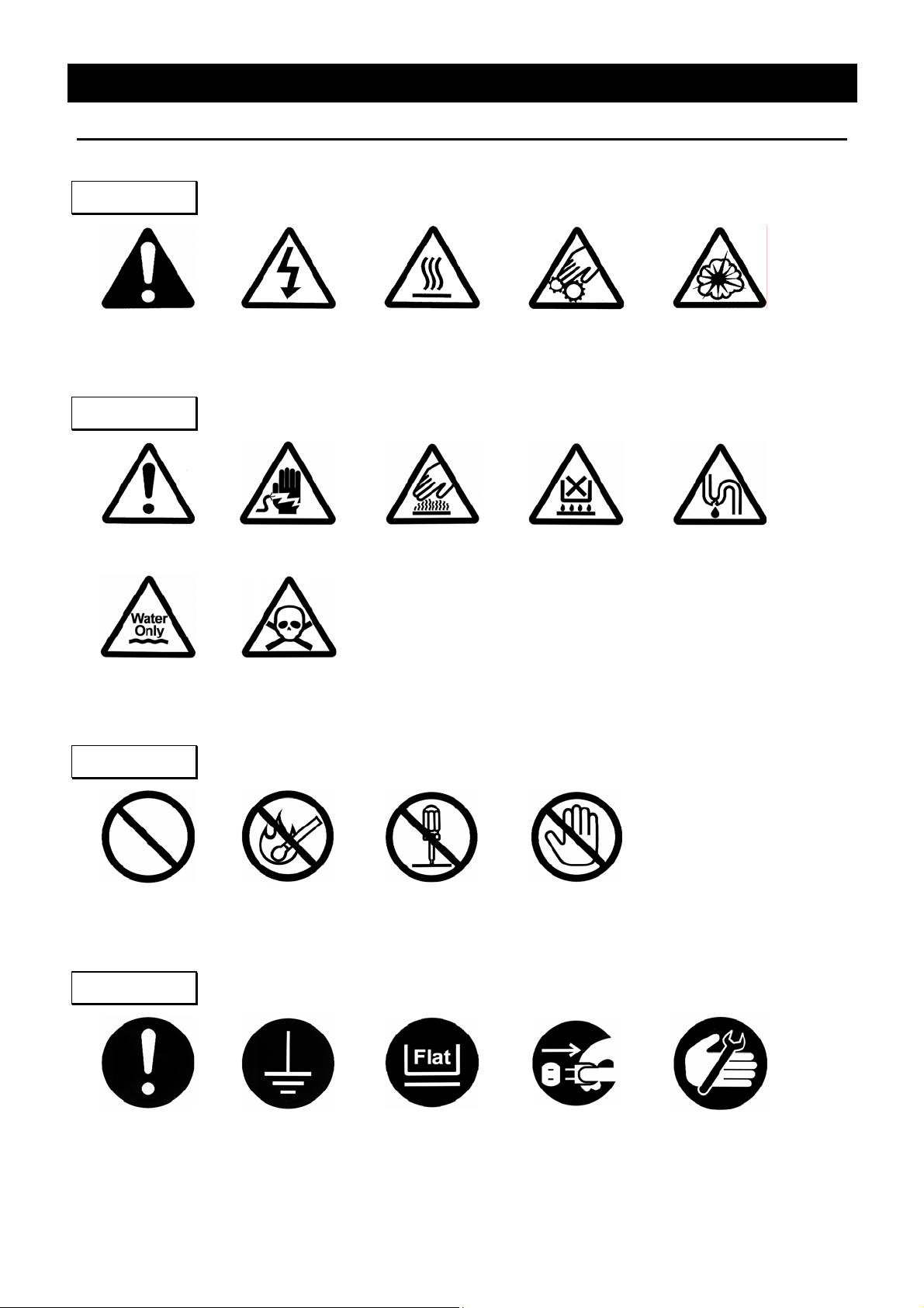
Table of Illustrated Symbols
Warning
Cautions in Using with Safety
Warning,
generally
Caution
Caution,
generally
Caution,
water only
Warning,
high voltage
Caution,
electrical shock
Caution,
deadly poison
Warning,
high temperature
Caution,
Warning,
drive train
Caution,
scald
no road heating
Warning,
explosive
Caution,
not to drench
Prohibit
Prohibit,
generally
Compulsion
Compulsion,
generally
inflammable
Compulsion,
connect to the
Prohibit,
grounding
terminal
to disassemble
Compulsion,
install on a flat
Prohibit,
surface
Prohibit,
to touch
Compulsion,
disconnect the
power plug
Compulsion,
periodical
inspection
2
Page 7
Cautions in Using with Safety
Fundamental Matters of “WARNING!” and “CAUTION!”
WARNING!
Do not use this unit in an area where there is flammable or explosive gas
Never use this unit in an area where there is flammable or explosive gas.
This unit is not explosion-proof. An a rc may be generated when the power switch is turned on or off,
and fire/explosion may result. (Refer to page28 “List of Dangerous Substances”.)
Always ground this unit
Always ground this unit on the power equipment side in order to avoid electrical shock due to a power
surge.
If a problem occurs
If smoke or strange odor should come out of this unit for some reason, turn off the power key right
away, and then turn off the circuit breaker and the main power. Immediately contact a service
technician for inspection. If this procedure is not followed, fire or electrical shock may result. Never
perform repair work yourself, since it is dangerous and not recommended.
Do not use the power cord if it is bundled or tangled
Do not use the power cord if it is bundled or tangled. If it is used in this manner, it can overheat and
fire may be caused.
Do not process, bend, wring, or stretch the power cord forcibly
Do not process, bend, wring, or stretch the power cord forcibly. Fire or electrical shock may result.
Pay special attention to the measure for flammability
and handling of flammable solvent
Leaving at the temperature higher than the room temperature may vaporize the flammable material
(ethanol, etc.). There might be the case that some flammable liquid might be vaporized at the
temperature lower than the room temperature. The result of such careless handling could cause the
fire or explosion. Do provide the vaporization with enough during the operation.
Do not disassemble or modify this unit
Do not disassemble or modify this unit. Fire or electrical shock or failure may be caused.
3
Page 8
Cautions in Using with Safety
Fundamental Matters of “WARNING!” and “CAUTION!”
CAUTION!
During a thunder storm
During a thunderstorm, turn off the power key immediately, then turn off the circuit breaker and the main
power. If this procedure is not followed, fire or electrical shock may be caused.
Do not touch ice in the trap bath
If touch the ice in the trap bath during operation or just after operation, the frostbite might be resulted
from low temperature. Therefore, do not touch the ice in the trap bath.
Do not touch the cooling fin with bare hands
Do not touch the cooling fin with bare hands during maintenance, for the edge of the cooling fin is too
sharp to cut your hand.
4
Page 9
Requirements for Installation
Before Using this unit
WARNING!
1. Always ground this unit
• Connect the power plug to a receptacle with grounding connectors.
• Do not forget to ground this unit, to protect you and the unit from electrical shock in case of
power surge. Choose a receptacle with grounding connectors as often as possible.
• Do not connect the grounding wire to a gas pipe, or by means of a lightning rod or telephone
line. A fire or electrical shock will occur.
• Do not use a branching receptacle, which may cause the heat generation.
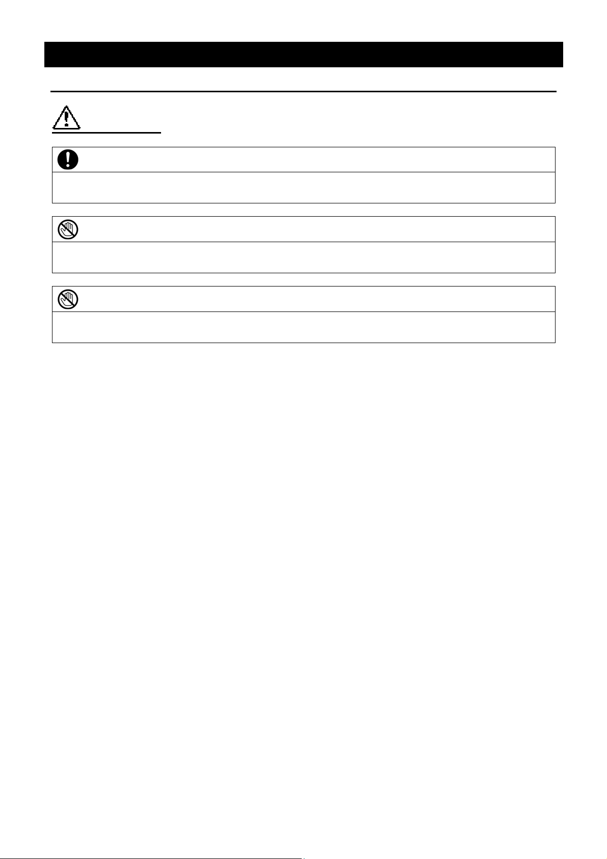
2. Choose a proper place for installation
• Do not install this unit in a place where:
♦ Rough or dirty surface.
♦ Flammable gas or corrosive gas is generated.
♦ Ambient temperature bellow 5℃ or above 30°C.
♦ Ambient temperature fluctuates violently.
♦ There is direct sunlight.
♦ There is excessive humidity and dust.
♦ There is a constant vibration.
♦ Winds from the air conditioner, etc. hit the sample container directly.
• Install this unit on a stable place with the space as shown below.
More than 40cm
More than
20cm
Main
Unit
Front side
More than
20cm
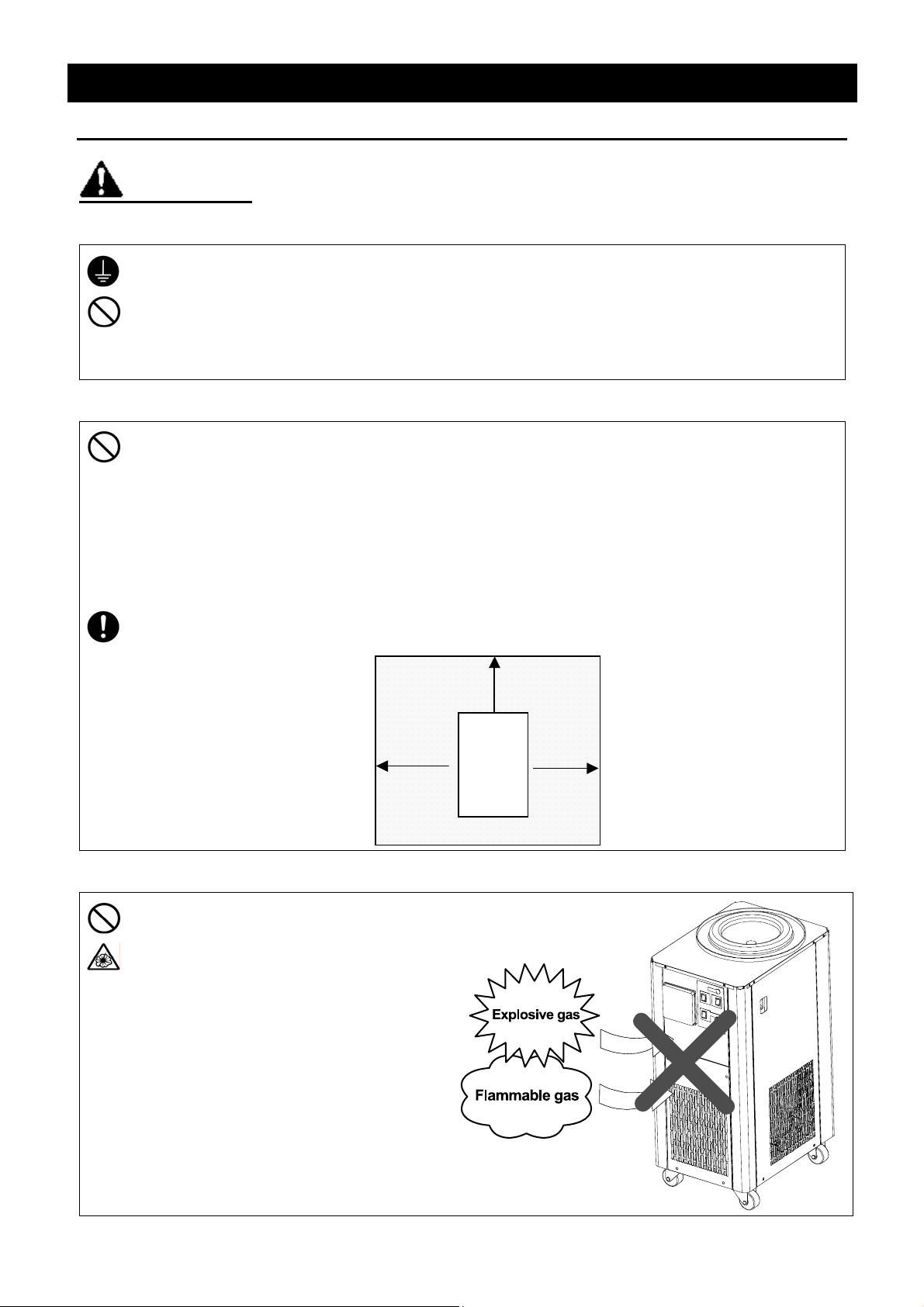
3. Do not use this unit in an area where there is flammable or explosive gas
• Never use this unit in an area where
there is flammable or explosive gas.
This unit is not explosion-proof. An arc
may be generated when the power
switch is turned ON or OFF, and
fire/explosion may result.
• To know about flammable or explosive
gas refer to page28 “List of Dangerous
Substances”.
爆発性ガス
可燃性ガス
5
Page 10
Requirements for Installation
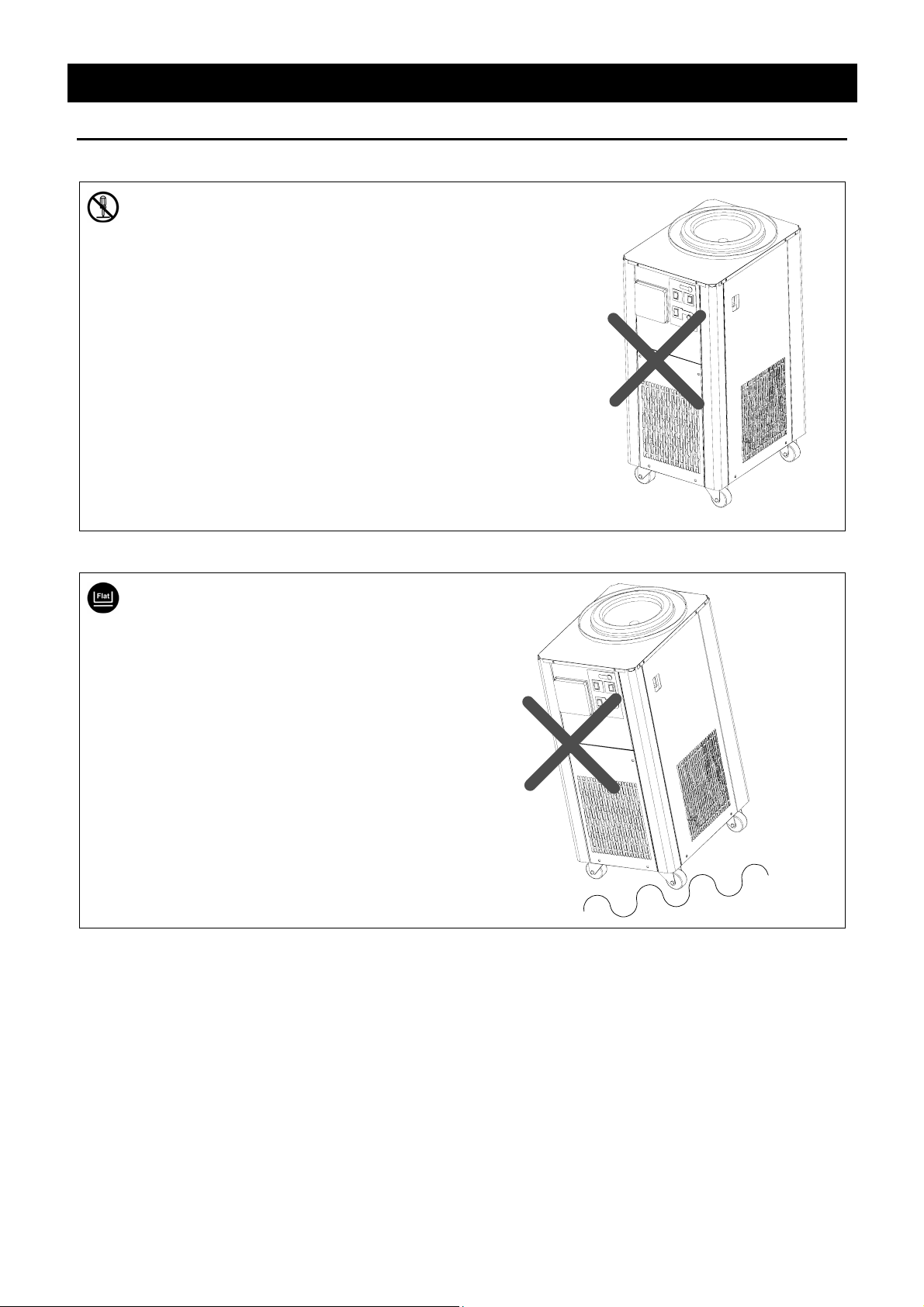
4. Do not modify
• Modification of this unit is strictly
prohibited. This could cause a failure.
Before Using this unit
5. Do not topple or tilt this unit
• Set this unit to the flattest place. This
unit incorporates the refrigerator. Do
not topple or tilt it. Setting this unit
on rough or slope place could cause
the vibration or noise, or cause the
unexpectible trouble or malfunction.
Modification
改造
6
Page 11

Requirements for Installation
Before Using this unit
CAUTION!
6. Use specified receptacle for power source
• Choose a correct power distribution board or receptacle that meets the unit’s rated electric
capacity.
Electric capacity: DC400: 100V AC, 50/60Hz, 6A (When using the pump, heater: 14A)
DC800: 100V AC, 50/60Hz, 11A (When using the pump, heater: 17A)
NOTE)
There could be the case that the unit does not run even after turning ON the power. Inspect
whether the voltage of the main power is lowered than the specified value, or whether other
device(s) uses the same power line of this unit. If the phenomena might be found, change the
power line of this unit to the other power line.
Starburst connection with a branching receptacle or extended wiring with a cord reel lowers
electrical power voltage, which may cause the degradation of refrigeration capability.
7. Before/after installing
• It may cause injure to a person if this unit falls down or moves by the earthquake and the
impact. etc..To prevent, take measures that the unit cannot fall down, and not install to busy
place.
• Though this unit has the air-cooled refrigerator, the device exhausts the heat. Do provide the
vaporization with enough so as not to raise the ambient temperature caused by the exhaust of
the heat, or install this unit with its air controlled completely. If the ambient temperature
becomes high, the operation efficiency becomes worse, and could cause the malfunction of
the device by high temperature and humidity.
8. Handling of power code
• Do not entangle the power cord. This will cause overheating and possibly a fire.
• Do not bend or twist the power cord, or apply excessive tension to it. This may cause a fire
and electrical shock.
• Do not lay the power cord under a desk or chair, and do not allow it to be pinched in order to
prevent it from being damaged and to avoid a fire or electrical shock.
• Keep the power cord away from any heating equipment such as a room heater. The cord's
insulation may melt and cause a fire or electrical shock.
• If the power cord becomes damaged (wiring exposed, breakage, etc.), immediately turn off the
power at the rear of this unit and shut off the main supply power. Then contact your nearest
dealer for replacement of the power cord. Leaving it may cause a fire or electrical shock.
• Connect the power plug to the receptacl which is supplied appropriate power and voltage.
7
Page 12

Installation Method
1. Unlock the stopper of the caster.
Pulling up the lever of the stopper for
caster releases the lock.
(Only the two casters in front of the unit
are attached the stopped.)
2. Move the device to the place to be
installed.
If there is a step on the floor, the too strong
impact is given to the caster, and could give
the damage. In that case, move the
device by lifting at the step.
3. When the installation place is determined,
pull down the lever of the stopped for
caster, and lock them.
4. Drain Tap Check
• Check whether the drain tap is detached
or not.
Release lock
Lock
Before Using this unit
Stopper
Caster
Drain tap
5. Power Plug Connection
Check the power of the earth leakage breaker is turned "OFF", and plug the power cord in the
receptacle.
6. Prepare the vacuum pump that the exhaust amount is 50 ・/min or more, and the ultimate pressure is
1.0X10
7. Install the vacuum valve to all of the valve mounting holes on the chamber.
8. Prepare a spare freeze dryer that can retain temperature sufficiently lower than the eutectic (crystal)
point of the sample.
-1
Pa. This pump must also have a check-valve.
8
Page 13

Main Unit
Front view
Vacuum gauge
Control panel
Description and Function of Each Part
Trap bath
Power switch
(Earth leakage breaker)
Ventilation port
Rear view
Receptacle for vacuum pump
Caster
Exhaust port
Power code
Drain tap
9
Page 14

Control Panel
Description and Function of Each Part
⑥
④
Part Name Function
① Refrigerator Switch:
⑤
DEFROST
ON
OFF
TROUBLE
REFRIGE
ON
OFF
②
PUMP
ON
OFF
→
START
The refrigerator activates by pressing “ON” of this switch.
①
③
② Vacuum Pump Switch:
③ Pump Start Switch:
④ Pirani Gauge:
⑤ Defrost Switch:
⑥ Refrigerator Trouble Lamp:
Enables pump operative.
Starts pump operation.
Displays degree of vacuum.
Melts frozen ice in the trap bath.
This lamp lights on when the refrigerator is in over lo ad.
10
Page 15

Operation Method
Pre-freezing
At pre-freezing process, quickly and completely freeze to the inside at sufficient lower
temperature than the eutectic (crystal) point
possible because thick ice layer might be easily melted by drying. Moreover, keep in mind that
it becomes easy to receive the heat of external temperature, and it may cause melting-ice if it
freezes widely on the container surface when the eutectic point of the sample is low.
Keep in mind that if there are too many throughput, or if the eutectic point of the sample is low,
a melting-ice phenomenon arises and this may cause bumping or scattering of the sample.
When installing the container and starting freeze-drying after pre-freezing process, set 3-4
minutes’ interval till next sample drying starts. (This differs depending on the container and
sample types.)
Melting-ice may be caused if the interval is too short.
Eutectic (Crystal) Point
Although pure water is frozen at 0 Celsius degree, solution is not frozen immediately below 0
Celsius degree, and the solution becomes soft ice condition because the frozen pure water and
the concentration solution that is not frozen are mixed.
Furthermore, if freezing is continued, all the solution will freeze uniformly under containing
its solutes, and will become solid ice in whole.
This temperature is called as the eutectic (crystal) point of the solution.
*
of the sample. Make the ice layer as thin as
11
Page 16

Operation Method
Procedure of Operation
Before operation, prepare a drying chamber, a vacuum pump, a vacuum hose, a tandem tube, etc.
Vacuum Pump: PD52 (YAMATO Product)
Exhaust amount: 50 ・/min, Ultimate pressure: 6.7×10⁻²Pa,
Diameter of inlet pipe: 18mm (or equivalent)
1. Supply the power
ON
2. Operation of the refrigerator
DEFROST
ON
OFF
REFRIGE
ON
OFF
3. Installation of chamber
Chamber for flask
installation
(Optional)
Trap packing
• Turn "ON" the earth leakage breaker.
• Turn "ON" the refrigerator switch. The refrigerator
activates.
There is the case that the starting sound of the refrigerator
might become higher depending on the operation initial status
and ambient temperature. However, this phenomenon is not
abnormal.
1. Make sure that there is no dust adhered to the trap packing
or the chamber for flask installation.
If any dent or dust is existed, degree of vacuum in the trap
bath becomes low.
2. Gently put the chamber for flask installation etc. on trap
packing.
If it has not stuck to trap packing enough, it will become the
cause of a vacuum leak.
The same is said of the case of a manifold etc.
Manifold A
12
Page 17

Procedure of Operation
Operation Method
4. Connection with the vacuum
pump
5. Connect the vacuum pump with
the rear receptacle
2
A
• Connect the vacuum hose to the exhaust port on the left
side.
(Exhaust port: outer shape 17 ㎜)
(Inside dia. of applicable vacuum hose: 12 X outer shape
30 ㎜)
Connect the opposite side of the vacuum hose to the inlet
of the vacuum pump.
The vacuum hose is not included.
Seal strength shall be improved by applying the vacuum seal
(silicon grease compound manufactured by TORAY, H.V.G,
etc) inside of the vacuum hose at connecting.
• Insert the power code of the vacuum pump into the 6A
receptacle of the rear side.
• Keep the switch of the vacuum pump ON.
Use the receptacle below 8A in total.
A
6
6. Make all valves for "VENT" to turn
up
"VENT"
7. Turn ON the vacuum pump switch.
Then, press Start switch once
PUMP
ON
OFF
→
START
• Make all valves for “VENT” face to turn up, and close the
path of the chamber side.
• After the trap bath becomes cold enough (if the lowest
temperature attainment time is over), start the vacuum
pump operation.
• The Lowest temperature attainment time:
(Outside temperature: 20℃, no load)
DC400: 50min., DC800: 80min.
This is guideline. (Condensation might be caused at the
bottom of the chamber.)
13
Page 18

Procedure of Operation
Operation Method
8. Check the vacuum gauge
9. Install a sample container, then,
turn up “VAC” face of the vacuum
valve
"VAC"
10. Container installation after second
piece
• Make sure that inside of the chamber attains vacuum with
the vacuum gauge. (10Pa-20Pa)
• Install the pre-frozen sample container to the vacuum
valve, then, turn up “VAC” face of the vacuum valve, and
open the path of the chamber side.
The sample container is decompressed and drying
process starts.
• When switching the vacuum valve setting from “VENT” to
“VAC”, inside of the chamber is pressurized. In case of
multiple samples processing at one time, wait (approx. 3-4
min.) till the pressure is returned, and then, switch the next
vacuum valve from “VENT” to “VAC”.
If installing multiple samples at one time, the degree of
vacuum decreases and the pre-frozen sample is melted.
This may cause the sample container broken.
First piece
11. End of freeze-drying
Second piece
• Finish the freeze-drying process after checking the sample
condition.
14
Page 19

Procedure of Operation
Operation Method
12. After freeze-drying process finished,
turn “VENT” face of the vacuum valve
upward
"VENT"
13. Return inside of the chamber to
normal atmosphere pressure
"VAC"
14.Turn OFF the vacuum pump
PUMP
ON
→
START
• Turn “VENT” face of the vacuum valve upward in order
to return the inside of the sample container to normal
atmosphere pressure. Then, remove the container.
Keep the container securely by hands so as not to fall.
• When drying of all samples are completed, and the
container is removed, turn one of the vacuum valves
gradually so that “VAC” face turns upward, and return
the inside of the chamber to normal atmosphere
pressure.
• Switch OFF the vacuum pump switch after the inside of
the chamber is returned to normal atmosphere
pressure.
OFF
15
Page 20

Defrost Operation
1. Remove the chamber for flask installation
Chamber for
flask installation
(Optional)
Operation Method
• Remove the chamber for flask installation.
If ice coating is formed on trap bath wall, turn ON
the defrost switch.
2. Remove ice
3. Drain water
Drain tap
• If the ice of the ice coating side is melted by
defrosting, take out the ice and turn OFF the defrost
switch.
• Defrosting is auto-stopped.
DC400: Approx. 20min.
DC800: Approx. 45min.
Switch OFF the defrost switch by manual.
• Remove the drain tap, and drain the water remained
in the bath with the drainage hose.
4. Stop operation
DEFROST
ON
OFF
ON
OFF
REFRIGE
1. Turn "OFF" the refrigerator switch.
2. Turn "OFF" the earth leakage breaker.
OFF
16
Page 21

Handling Precautions
WARNING!
If a problem occurs
If smoke or strange odor should come out of this unit for some reason, turn off the power key
right away, and then turn off the breaker and the main power. Immediately contact a service
technician for inspection. If this procedure is not followed, fire or electrical shock may result.
Never perform repair work yourself, since it is dangerous and not recommended.
Measure for flammability and handling of flammable solvent
This unit is not designed as the explosion-proof construction. Pay special attention to the
handling of the sample to be handled with this unit on the consumption with the explosive
material, flammable material, and similar ones. The flammable material may be vaporized by
leaving it at the temperature higher than room temperature, and could cause the fire or
explosion. When ha ndling such material, provide ventilation with enough before the operation.
(Refer to page 28 “List of Dangerous Substances”.)
CAUTION!
Maximum trap capacity
The max. trap capacity of the bath in this DC400/800 is approx. 0.6・/1.0・. Excessive amount
shall cause significant unit performance degradation.
Do not step on this unit
Do not step on this unit. It will cause injury if this unit fall down or break.
Do not put anything on this unit
Do not put anything on this unit. It will cause injury if fall.
During a thunder storm
During a thunderstorm, turn off the power key immediately, then turn off the circuit breaker and
the main power. If this procedure is not followed, fire or electrical shock may be caused.
Countermeasure for stop operation during night or long-term stop
In case of stopping operation during night or long-term, toggle the power switch to "OFF".
Power supply voltage
The power supply voltage must be within +/-10% of the rated voltage.
Do not use solutions
The rubber packing of the unit and U-ring on the chamber cap for the vacuum valve and the flask
are made of chloroprene rubber. Keep in mind that they may be immersed by acid, halogen,
aromatic series, ester, and the oxo solvent.
Restarting
Stop operation and wait over 5 minutes, and then, restart operation.
17
Page 22

Upper limit of inside bath temperature
Do not operate continuously when the temperature of the bath is higher than -20℃.
Vacuum grease application
If there is any dirt adhered to each connecting part of the vacuum system, the degree of vacuum
might be degreased. In this case, wipe the dirt off, and then, apply the vacuum grease.
In case that the stem tube of the vacuum valve is hard to rotate, remove the stem tube once and
apply the vacuum grease, and then install the stem tube again.
When returning to normal atmosphere pressure
Before turning OFF the vacuum pump, make sure that inside of the chamber is returned to
normal atmosphere pressure after operation finished. If turning OFF the vacuum pump under
vacuum condition, the oil inside of the pump might be flown back in the chamber. (Refer to “12.
After freeze-drying process finished, turn “VENT” face of the vacuum valve upward” in
P.15 for the procedure of vacuum relief.)
Handling Precautions
Dimension of ampoule
Use an ampoule that diameter of the connecting hole is approx. 7-9mm since the inner diameter
of the ampoule adapter is 7mm.
Eggplant flask
Use TS29 for grinding eggplant flask.
18
Page 23

Daily Inspection and Maintenance
Maintenance Method
WARNING!
• Disconnect the power cable from the power source when doing an inspection or maintenance
unless needed.
• Perform the daily inspection and maintenance after returning the temperature of this unit to the
normal one.
• Do not disassemble this unit.
• Do not touch the cooling fin with bare hands.
CAUTION!
• Use a well-drained soft cloth to wipe dirt on this
unit. Do not use benzene, thinner or cleanser for
wiping. Do not scrub this unit. Deformation,
deterioration or color change may result in.
Monthly maintenance
• Check the earth leakage breaker function.
1. Connect the power cord.
2. Turn the breaker on.
3. Push the red test switch by a ballpoint pen etc.
4. If there is no problem, the earth leakage breaker will be turned off.
Cleaning of cooling fin
• Clogging of the cooling fin could cause the deterioration of the
cooling performance, and also cause the malfunction of the
refrigerator. The clogged status differs depending on the
surrounding condition or operation time. Clean the cooling
fin periodically.
Loosen the mounting screws (4 screws) of the ventilation port
cover, remove the cover of the ventilation port, and remove the
dust attached to the surface of the cover using the vacuum
cleaner.
After cleaning the cooling fin, att ach it in inverse procedure.
Take care not to crush the fin during cleaning.
For any questions, contact the dealer who you purchased this unit from, or the nearest sales
division in our company.
19
Page 24

Long storage and disposal
When not using this unit for long term / When disposing
CAUTION!
When not using this unit for long term…
• Turn off the power and disconnect the power cord.
WARNING!
When disposing…
• Keep out of reach of children.
Environmental protection should be considered
We request you to disassemble this unit as possible and recycle the reusable parts considering to
the environmental protection. The feature components of this unit and materials used are
listed below.
Component Name Material
Parts of Main Unit
Casing Bonderizing steel plate baked with melamine resin coating
Inner bath, Cover Stainless steel SUS304, Acryl
Production plates Polyester (PET) resin film
Corner Alkylbenzenesulfied (ABS) resin
Trap packing Silicon rubber
Electrical Parts
Switches, Relays Composites with resin and others
Power cord & wiring
materials and others
Parts of Refrigeration System
Refrigerator unit Iron, Synthetic oil and others
Cooling fin Aluminum, Copper
Parts of Piping
Drain hose Natural rubber
Drain tap Polyacetal resin
Drain tap holder Bonderizing steel plate baked with melamine resin coating
Pipe cover Polyurethane sponge
Pipe Copper
Sealed Cooling Medium for Refrigerator
Cooling medium
Composites with synthetic rubber, copper, nickel and others
DC400 DC800
R404A 300g 450g
R23 -
560 ・
Ask the specialist for the dealing of cooling medium.
20
Page 25

Trouble Shooting
Condition Possible Causes
The device does not start when
turning on the power switch.
Not fallen the temperature.
In lighting on the lamp,
In the Event of Failure…
• Power plug is not connected to the receptacle correctly.
• Power failure.
• Earth leakage breaker is turned to “OFF”
• The cooling fin is clogged.
• The cooling sample is overheated.
• The ambient temperature is exceeding 30℃.
• The peripheral of the ventilating port is shut down.
Error Sign Cause Remedy
• Immediately turn off the power, remove the cause of
Turned on
the refrigerator
trouble lamp
In the case if the error other than listed above occurred, turn off the power switch and primary
power source immediately. Contact the shop of your purchase or nearest Yamato Scientific
Service Office.
Overload of refrigerator
the error referring to the "Trouble Shooting" (Not
fallen the temperature) above, and turn on the power
again after passing the certain time.
• In case of lighting the alarm lamp again, make a call
to the service office.
21
Page 26

After Service and Warranty
In Case of Request for Repair
If the failure occurs, stop the operation, turn OFF the power switch, and unplug the power plug.
Please contact the sales agency that this unit was purchased, or the Yamato Scientific's sales
office.
< Check following items before contact >
◆ Model Name of Product
◆ Production Number
◆ Purchase Date
◆ About Trouble (in detail as possible)
Minimum Retention Period of Performance Parts for Repair
The minimum retention period of performance parts for repair of this unit is 7 years after
discontinuance of this unit.
The "performance part for repair" is the part that is required to maintain this unit.
See the production plate attached to this unit.
22
Page 27

Specification
Main Unit
Model DC400 DC800
Method Storage water heater body cooling method
Dehumidifying capacity Max. 0.6kg Max. 1.0kg
Lowest reached
temperature ※
Time required to reach
Performance
lowest temperature ※
Refrigerator Air cooling, 300W
Cooling medium R404a R404a/R23
Pressure indication gauge Pirani gauge
Exhaust port
Chamber material SUS304, Cylindrical
Configuration
Dimensions of chamber
Capacity Approx. 4L
Usable ambient temperature
External dimensions
Weight Approx. 32Kg Approx. 54Kg
Standards
Power supply 100V AC, 50/60Hz, 6A 100V AC, 50/60Hz, 11A
Accessories
※: Operation conditions: Outside air temperature = 20℃, no load
50min. (20℃ to -45℃) 80min. (20℃ to -80℃)
W284×D404×H700 mm W405×D455×H850 mm
Vacuum silicon grease (TORAY H.V.G), Vacuum hose (φ20×φ30
×1.5m), Instruction manual for main unit, Instruction manual for
Pirani gauge
-45℃ -80℃
Air cooling, 350W×2
φ17mm
φ153×H235mm
5 to 30℃
23
Page 28

Optional Accessories
Name Specification Product code
Mounting cock Inner dia.: 18.5mm
Chamber for flask installation
Manifold A
Manifold B
Dry chamber
Stopper type dry chamber
Dry flask
Dry flask cap (with glass joint)
Serum bottle (Vial bottle)
Adapter for ampoule
Adapter for test tube
(with glass joint)
Adapter for egg plant flask
(female)
Adapter for egg plant flask
(male)
Glass joint
Micro tube holder
※: Conditions: Room temperature = 20℃, no load
Mounting cock pitch 96mm
Number of port 12
Dimensions
Mounting cock Inner dia.: 18.5mm
Mounting cock pitch 80mm
Number of port 8
Dimensions
Mounting cock Inner dia.: 18.5mm
Mounting cock pitch 80mm
Number of port 16
Dimensions
Number of shelves 1
60mm dish, Number of falls 7
Temperature adjustment
Dimensions
Number of shelves 1
60mm dish, Number of falls 7
Temperature adjustment
Dimensions
120m ・・5 pcs.
250m ・・5 pcs.
Straight・5 pcs.
45°bent・5 pcs.
50m ・・10 pcs.
30m ・・10 pcs.
10m ・・10 pcs.
Single・5 pcs.
Double・5 pcs.
Triple・5 pcs.
Straight 212590
45°bent
TS29 grinding or equivalent 212569
TS29 grinding 212597
Straight 212598
45°bent
1.5m ・×24 pcs. mountable
Specification
φ195×H303 mm
W304×D60×H263 mm
W624×D60×H263 mm
30℃±2℃ ※
φ252×H240 mm
30℃±2℃ ※
φ252×H425 mm
212560
212561
212562
212563
212564
212820
212821
212570
212571
212814
212815
212816
212572
212573
212574
212591
212599
212580
24
Page 29

DC400
4
Wiring Diagram
RF
C
R
OVR
6
X5-2
4
6
X4
2
7
X2-1
1
X3
6
X2
11
10
3
3
PCT
X
2
1
S
1
C1
2
3
Receptacle
Timer (Auto defrost)
Timer
Start relay
Overload relay
Operation condenser
Start condenser
Refrigerator
T1
C2
CN
T2
PTC
OVR
C1
C2
RF
REFsw
1
1a
X5-1
1
PSsw
5
DEFsw
1
1a
VACsw1
1
1a
2
9
X1-2 X1-3 X6
8
5
1
VACsw2
NO
7
2
6
6
5
2
REF
T1-2
12
48
T2
9
5
T1-1
X1-1
VAC
9
DEF
2a
NO
4
X1
10
2a
2
X2-2
2
2a
1
11
8
PS
7
8
X5
7
8
MV2 X4
Switch (Vacuum gauge)
Pressure switch
Lamp (VACsw built-in)
Lamp (DEFsw built-in)
Lamp (REFsw built-in)
Lamp (Pressure)
Pirani gauge
PA
Switch (Defrost)
DEFsw
Sensor (Vacuum gauge)
TH
Switch (Refrigerator)
REFsw
7
8
X3
T2
13
14 3m
T1
13
14 20m
7
8
X6
X2-3
3
9
MV1
MV3
PA
Pasw
Relay (Refrigerator)
X3
PSsw
Relay (Refrigerator stop)
X4
VAC
Relay (Pressure error)
X5
DEF
Relay (Solenoid valve)
X6
REF
Switch (Pump)
VACsw1
PS
Switch (Pump start)
VACsw2
P
1
ELB
AC100V
2
CN
FM
3
4
TH
Earth leakage breaker
Terminal block
Fan motor (Refrigerator)
Solenoid valve (Refrigerator)
Solenoid valve (Defrost)
Solenoid valve (VAC)
Relay (VAC)
Relay (Refrigerator, Pump stop)
P
ELB
FM
MV1
Mv2
Mv3
X1
X2
25
Page 30

DC800
Timer (Refrigerator delay)
T3
Start relay
PTC
Wiring Diagram
Overload relay
Operation condenser
Start condenser
Refrigerator
C1, 3
C2, 4
OVR1, 2
RF1, 2
Lamp (VACsw built-in)
VAC
Relay (Refrigerator stop)
X4
Lamp (DEFsw built-in)
DEF
Relay (Pressure error)
X5
Lamp (REFsw built-in)
REF
Relay (Solenoid valve)
X6
Lamp (Pressure)
PS
Switch (Pump)
VACsw1
Pirani gauge
PA
Switch (Pump start)
VACsw2
Sensor (Vacuum gauge)
TH
Switch (Defrost)
DEFsw
Receptacle
Timer (Auto defrost)
T1
CN
Switch (Refrigerator)
Switch (Vacuum gauge)
Pasw
REFsw
Timer
T2
Pressure switch
PSsw
Earth leakage breaker
Terminal block
Fan motor (Refrigerator)
Solenoid valve (Refrigerator)
Solenoid valve (Defrost)
Solenoid valve (VAC)
Relay (VAC)
Relay (Refrigerator, Pump stop)
Relay (Refrigerator)
P
ELB
26
FM
MV1
Mv2
Mv3
X1
X2
X3
Page 31

Replacement Parts Table
Common Parts
Symbol Part Name Specification Manufacturer Code No.
MV1 Solenoid valve (Refrigerator) NEV-603DXF Saginomiya 3-02-006-0004
MV2 Solenoid valve (Defrost) SEV-502DXF Saginomiya 3-02-006-0003
MV3 Solenoid valve (VAC) AG33022 AC100V CKD 3-20-001-0018
ELB Earth leakage breaker BJS203 Matsushita 2-06-005-0011
X3, 4, 6 Relay LY1F AC100V OMRON LT-00000992
X1, 2 Relay LY3F AC100V OMRON LT00000993
T2, 3 Timer (Auto defrost) ADX11134 Matsushita 2-05-000-0053
T1 Timer ADX11184 Matsushita LT00000994
DEFsw
PEFsw
VACsw2 Switch CW-SB21NYKZYEF Nihon Kaiheiki 2-55-000-0017
Switch CW-SB21NMKZMEF Nihon Kaiheiki 2-55-000-0011
VACsw1 Switch A3CT-90A0-Y OMRON LT00000995
PS Lamp (Pressure) BN5665L AC100V Satoh Parts LT00000996
CN Receptacle S-160-A21 Satoh Parts LT00001003
PA Pirani gauge GP-1 (WP-02 with sensor) ULVAC LT00001004
PSsw Pressure switch VHP-F Fuji Kohki 3-18-000-0006
For DC400
Symbol Part Name Specification Manufacturer Code No.
RF Compressor C-2SN300LOU Sanyo C&C 3-01-006-0004
FM Fan motor SE4-C041NP Sanyo C&C 3-01-006-0006
P Terminal block M011-OFX4P Toyo Giken 2-07-023-0001
X5 Relay LY2F AC100V OMRON 2-05-000-0035
For DC800
Symbol Part Name Specification Manufacturer Code No.
RF1 Compressor C-2SN350LOU Sanyo C&C 3-01-006-0005
RF2 Compressor C-2SN350LOU (oil less) Sanyo C&C 3-01-006-0008
FM Fan motor SE4-D11LP Sanyo C&C 3-01-006-0014
P Terminal block M011-OFX5P Toyo Giken 2-07-023-0002
X5 Relay LY3F AC100V OMRON LT00000993
27
Page 32

List of Dangerous Substances
Never use explosive substances, flammable substances and substances that include explosive
or flammable ingredients in this unit.
EXPLOSIVE
Ethylene glycol dinitrate (nitro glycol), Glycerin trinitrate (nitroglycerine), Cellulose
nitrate (nitrocellulose), and other explosive nitrate esters
Reference
EXPLOSIVE:
FLAMMABLE
IGNITING:
OXIDIZING:
Trinitrobenzene, Trinitrotoluene, Trinitrophenol (picric acid), and other explosive
nitro compounds
Acetyl hidroperoxide (peracetic acid), Methyl ethyl ketone peroxide, Benzyl
peroxide, and other organic peroxides
Lithium (metal), Potassium (metal), Sodium (metal), Yellow phosphorus,
Phosphorus sulfide, Red phosphorus, Celluloid compounds, Calcium carbide,
Lime phosphate, Magnesium (powder), Aluminum (powder), Powder of metals
other than magnesium and aluminum, Sodium hydrosulfite
Potassium chlorate, Sodium chlorate, Ammonium chlorate, and other chlorate
Potassium perchlorate, Sodium perchlorate, Ammonium perchlorate, and other
perchlorate
Potassium peroxide, Sodium peroxide, Barium peroxide, and other inorganic
peroxide
Potassium nitrate, Sodium nitrate, Ammonium nitrate, and other nitrate
Sodium chlorite and other chlorites
Calcium hypochlorite and other hypochlorites
Ethyl ether, Gasoline, Acetaldehyde, Propylene chloride, Carbon disulfide, and
other flammable substances having a flash point of lower than -30℃
INFLAMMABLE
LIQUID:
FLAMMABLE
GAS:
Normal hexane, ethylene oxide, acetone, benzene, methyl ethyl ketone, and
other flammable substances having a flash point of -30℃ or higher but lower
than 0℃
Methanol, Ethanol, Xylene, Pentyl acetate (amyl acetate), and other flammable
substances having a flash point of 0℃ or higher but lower than 30℃
Kerosene, Light oil (gas oil), Oil of turpentine, Isopentyl alcohol (isoamyl alcohol),
Acetic acid, and other flammable substances having a flash point of 30℃ or
higher but lower than 65℃
Hydrogen, Acetylene, Ethylene, Methane, Propane, Butane, and other flammable
substances which assume a gaseous state at 15℃ and 1 atm
(Source: Appendix Table 1 of Article 6 of the Industrial Safety and Health Order in Japan)
28
Page 33

Responsibility
Please follow the instructions in this document when using this unit. Yamato Scientific has no
responsibility for the accidents or breakdown of device if it is used with a failure to comply.
Never conduct what this document forbids. Unexpected accidents or breakdown may result in.
Note
◆ The contents of this document may be changed in future without notice.
◆ Any books with missing pages or disorderly binding may be replaced.
Instruction Manual for
Freeze Dryer
Model DC400/800
Second Edition Apr. 22, 2005
Yamato Scientific Co., Ltd.
2-1-6 Nihonbashi Honcho, Chuo-ku,
Tokyo, 103-8432, Japan
http://www.yamato-net.co.jp
29
 Loading...