


g
Coolline
Model
CLS301/400/600
Instruction Manual
- Third Edition -
z Thank you for purchasing "Coolline, CLS Series"
of Yamato Scientific Co., Ltd.
z To use this unit properly, read this "Instruction
Manual" thoroughly before using this unit.
Keep this instruction manual around this unit for
referring at anytime.
WARNING!:
Carefully read and thoroughly understand the
important warning items described in this
manual before usin
this unit.
Yamato Scientific Co. LTD.

Contents
Cautions in Using with Safety................................................................1
Explanation.................................................................................................................... 1
•
•
Table of Illustrated Symbols .......................................................................................... 2
Fundamental Matters of "WARNING!" and "CAUTION!"............................................... 3
•
Before Using This Unit ...........................................................................4
Requirements for Installation......................................................................................... 4
•
•
Installation Procedure.................................................................................................... 7
Description and Function of Each Part.................................................9
Main Unit .......................................................................................................................9
•
Control Panel............................................................................................................... 10
•
•
Operation Monitor........................................................................................................ 11
•
Characters of the Controller ........................................................................................ 12
Operation Method .................................................................................13
Operation Mode and Function List .............................................................................. 13
•
•
Operation Mode, Function Setting Key, and Characters ............................................. 15
•
Fixed Temperature Operation...................................................................................... 16
•
Quick Auto Stop Operation .......................................................................................... 18
•
Auto Stop Operation.................................................................................................... 20
•
Auto Start Operation.................................................................................................... 23
Calibration Offset Function.......................................................................................... 26
•
•
Lock Function.............................................................................................................. 27
•
Power Failure Compensation Function ....................................................................... 28
•
Addition Time Function................................................................................................ 29
•
Temperature Output Terminal...................................................................................... 30
•
Cooling curve, cooling capacity curve (reference data)............................................... 32
•
Nybrine freezing temperature and viscosity (reference data)...................................... 36
Handling Precautions ...........................................................................37
Maintenance Method.............................................................................39
• Daily Inspection and Maintenance .............................................................................. 39
Long storage and disposal...................................................................41
When not using this unit for long term / When disposing ............................................ 41
•
In the Event of Failure….......................................................................42
• Safety Device and Error Code..................................................................................... 42
•
Trouble Shooting......................................................................................................... 43
After Service and Warranty ..................................................................44

Specification..........................................................................................45
Wiring Diagram......................................................................................46
• CLS300 ....................................................................................................................... 46
•
CLS400 ....................................................................................................................... 47
•
CLS600 ....................................................................................................................... 48
Replacement Parts Table......................................................................49
Reference...............................................................................................50
List of Dangerous Substances .................................................................................... 50
•
Installation Standard Manual................................................................51

Explanation
Illustrated Symbols
Various symbols are used in this safety manual in order to use the unit without
danger of injury and damage of the unit. A list of problems caused by ignoring
the warnings and improper handling is divided as shown below.Be sure that you
understand the warnings and cautions in this manual before operating the unit.
Cautions in Using with Safety
MEANING OF ILLUSTRATED SYMBOLS
WARNING!
CAUTION!
If the warning is ignored, there is the danger of a problem that
may cause a serious accident or even fatality.
If the caution is ignored, there is the danger of a problem that may
cause injury/damage to property or the unit itself.
Meaning of Symbols
This symbol indicates items that urge the warning (including the caution).
A detailed warning message is shown adjacent to the symbol.
This symbol indicates items that are strictly prohibited.
A detailed message is shown adjacent to the symbol with specific actions not to
perform.
This symbol indicates items that should be always performed.
A detailed message with instructions is shown adjacent to the symbol.
1

Ta ble of Illustrated Symbols
Warning
Cautions in Using with Safety
Warning,
generally
Caution
Caution,
generally
Caution,
water only
Warning,
high voltage
electrical shock
deadly poison
Caution,
Caution,
Warning,
high temperature
Caution,
scald
Warning,
drive train
Caution,
no road heating
Warning,
explosive
Caution,
not to drench
Prohibit
Prohibit,
generally
Compulsion
Compulsion,
generally
connect to the
Prohibit,
inflammable
Compulsion,
grounding
terminal
to disassemble
Compulsion,
install on a flat
Prohibit,
surface
Prohibit,
to touch
Compulsion,
disconnect the
power plug
Compulsion,
periodical
inspection
2

Cautions in Using with Safety
Fundamental Matters of "WARNING!" and "CAUTION!"
WARNING!
Do not use this unit in an area where there is flammable or explosive gas
Never use this unit in an area where there is flammable or explosive gas. This unit is not
explosion-proof. An arc may be generated when the POWER switch is turned on or off, and
fire/explosion may result. (Refer to page 50 "List of Dangerous Substances".)
Always ground this unit
Always ground this unit on the power equipment side in order to avoid electrical shock due to a power
surge.
If a problem occurs
If smoke or strange odor should come out of this unit for some reason, turn off the circuit breaker right
away, and then disconnect the power plug. Immediately contact a service technician for inspection. If
this procedure is not followed, fire or electrical shock may result. Never perform repair work yourself,
since it is dangerous and not recommended.
Do not use the power cord if it is bundled or tangled
Do not use the power cord if it is bundled or tangled. If it is used in this manner, it can overheat and
fire may be caused.
Do not process, bend, wring, or stretch the power cord forcibly
Do not process, bend, wring, or stretch the power cord forcibly. Fire or electrical shock may result.
Substances that can not be used
Never use explosive substances, flammable substances and substances that include explosive or
flammable ingredients in this unit. Explosion or fire may occur. (Refer to page 50 "List of Dangerous
Substances".)
Do not disassemble or modify this unit
Do not disassemble or modify this unit. Fire or electrical shock or failure may be caused.
Do not touch high-temperature parts
Some of the parts may become hot during and just after operation. It may cause burns.
CAUTION!
During a thunder storm
During a thunderstorm, turn off the power key immediately, then turn off the circuit breaker and the main
power. If this procedure is not followed, fire or electrical shock may be caused.
3
Requirements for Installation
1. Always ground this unit
• Be sure to connect the earth wire (the green cable of power cord) to the grounding conductor
or ground terminal to prevent accidents caused by electric leakage.
• Do not connect the earth wire to gas or water pipes. If not, fire disaster may be caused.
• Do not connect the earth wire to the ground for telephone wire or lightning conductor. If not,
fire disaster or electric shock may be caused.
• Do not use a branching receptacle, which may cause the heat generation.
2. Choose a proper place for installation
• Do not install this unit in a place where:
♦ Rough or dirty surface.
♦ Flammable gas or corrosive gas is generated.
♦ Ambient temperature above 30°C.
♦ Ambient temperature fluctuates violently.
♦ There is direct sunlight.
♦ There is excessive humidity and dust.
♦ There is a constant vibration.
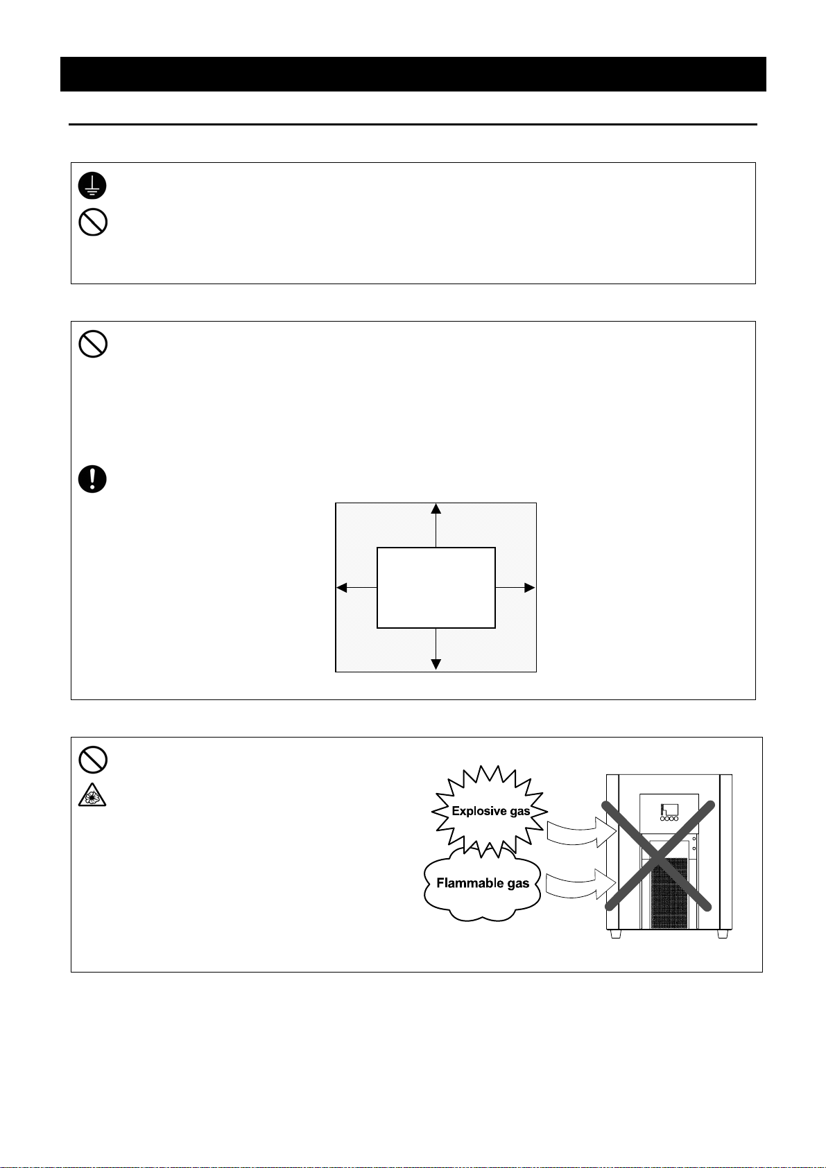
• Install this unit on a stable place with the space as shown below.
Before Using This Unit
More than 20cm
More than
20cm
Main Unit
More than 20cm
More than
20cm
3. Do not use this unit in an area where there is flammable or explosive gas
• Never use this unit in an area where
there is flammable or explosive gas.
This unit is not explosion-proof. An arc
may be generated when the POWER
switch is turned ON or OFF, and
fire/explosion may result.
• To know about flammable or explosive
gas, refer to page 50 “List of Dangerous
Substances”.
爆発性ガス
4

Requirements for Installation
4. Do not modify
• Modification of this unit is strictly prohibited.
This could cause a failure.
5. Installation on horizontal surface
• Place this unit as flat a place as possible. If
the rubber feet (model CLS301) or casters
(models CLS400/600) are not in uniform
contact with the floor surface, noise or
vibration may result. Additionally, the unit
may cause a problem or malfunction.
Before Using This Unit
Modification
改造
6. Choose a correct power distribution board or receptacle
• Choose a correct power distribution board or receptacle that meets the unit’s rated electric
capacity.
Electric capacity:
NOTE)
There could be the case that the unit does not run even after turning ON the power. Inspect
whether the voltage of the main power is lowered than the specified value, or whether other
device(s) uses the same power line of this unit. If the phenomena might be found, change the
power line of this unit to the other power line.
CLS301: 100V AC, 4A
CLS400: 100V AC, 6A
CLS600: 100V AC, 10A
7. Before/after installing
• It may cause injure to a person if this unit falls down or moves by the earthquake and the
impact. etc..To prevent, take measures that the unit cannot fall down, and not install to busy
place.
5
Before Using This Unit
Requirements for Installation
8. Handling of power code
• Do not entangle the power cord. This will cause overheating and possibly a fire.
• Do not bend or twist the power cord, or apply excessive tension to it. This may cause a fire
and electrical shock.
• Do not lay the power cord under a desk or chair, and do not allow it to be pinched in order to
prevent it from being damaged and to avoid a fire or electrical shock.
• Keep the power cord away from any heating equipment such as a room heater. The cord's
insulation may melt and cause a fire or electrical shock.
• If the power cord becomes damaged (wiring exposed, breakage, etc.), immediately turn off the
power at the rear of this unit and shut off the main supply power. Then contact your nearest
dealer for replacement of the power cord. Leaving it may cause a fire or electrical shock.
• Connect the power plug to the receptacle which is supplied appropriate power and voltage.
9. Use a proper circulating fluid in response to working conditions
• Select a circulating fluid according to the working temperature.
Set temperature + 10°C or over: Water
Set temperature + 10°C or below: Antifreezing fluid (Nybrine
If water is used at the set temperature of + 10°C or below, the cooling coil may freeze to cause
malfunction.
10. When using a Nybrine aqueous solution instead of water
• The freezing point of the antifreezing fluid depends on its concentration or type. Use an
antifreezing fluid having a 10°C lower at least than the working temperature. Any antifreezing
fluid, which freezes at a higher temperature than that, may freeze in the cooling unit and
deteriorates heat exchanging efficiency.
®
- 60%, ethylene glycol - 50%)
11. Do not use fluids other than water and antifreezing fluids (Nybrine®, ethylene glycol)
• Pour distilled water or tap water into the water tank. Water of poor quality may cause fur or
scale to accumulate on the heater pump, which may result in deteriorated performance or
malfunction (e.g. well water, etc.).
• A circulating fluid with high specific gravity or highly viscosity places overburden on the
circulating pump and damages the unit (e.g. Fluorinert, Galden, etc.).
• A corrosive fluid or a fluid that produces corrosive substances when heated may cause
malfunction (e.g. Fluorinert).
• Do not use any fluid whose vapor is toxic or hazardous because it may result in an accident
(methyl alcohol, etc.).
6
Before Using This Unit
Installation Procedure
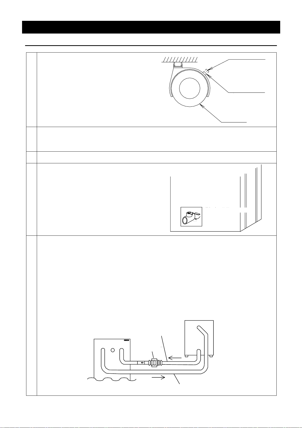
1 Release the stopper lock of the casters.
(CLS400/600)
Push down the stopper button of the casters as
shown in the right figure. It will be unlocked.
(Only the two casters on the front side of the unit
are equipped with a caster.)
The model CLS301 is equipped with rubber feet.
2 Move the unit to the place of installation.
If there is a bump on the floor, the casters may receive excessive load and get damaged. In this
case, lift and move the unit.
3 After the unit is placed in the desired position, lock the stopper button of the casters.
キャスター
Caster
ボタン位置(高)
Button position: high
ロック状態(据付)
Locked
(during installation)
ボタン位置(低)
Button position: low
プッシュでロック解除
Push to unlock the
(移動可)
caster (movable)
4 Check the drain cock.
Confirm that the drain cock on the right side of
the unit is in the "Close" position (perpendicular
to the cock).
閉 運転時の位置
Position during operation
Close
Open
開
Position during draining
排水時の位置
5 Connect the hoses.
• Securely connect the hoses to the ports of the unit and the external water tank of the external
open system so that the fluid does not leak. See the figure shown below. The outside
diameter of both discharge (OUT) and return (IN) ports is each 13 mm.
Note) Connect the priming pump port (IN) to the return (IN) port of the unit.
• Using a solenoid or throttle valve to shut off the circulating path may result in malfunction of the
circulating pump or fluid leakage.
• Do not throttle the path excessively. Keep a flow rate of the circulating fluid at 1.5·/min or over.
• Slowly change the flow rate. A rapid change in the flow rate may reduce the service life of the
circulating pump.
External water tank
CLH unit
本 体
Discharge
吐出口
(OUT)
(OUT)
Return
戻り口
(IN)
(IN)
Insulation hose with
呼び水ポンプ付
a priming pump
断熱ホース
呼び水ポンプ
Priming pump
外部水槽
IN
OUT
IN
断熱ホース
Insulation hose
7

Before Using This Unit
Installation Procedure
6 Connecting the power.
Confirm that the leakage breaker and the POWER switch are turned "OFF", and then plug into an
outlet.
7 Installing the external water tank (optional accessory)
Install the external water tank in a higher place than the unit. If it is installed in a lower place, the
flow rate may drop or air bleeding may not be carried out smoothly when pouring the circulating fluid
for the first time.
8 Pour the circulating fluid into the water tank.
• Remove the lid from the external water tank, and pour the circulating fluid.
(Select a circulating fluid in response to the set temperature condition.)
• Open the air release valve cock.
• Push the priming pump more than ten times.
(Feed the fluid from the external water tank to the circulating pump inside the unit to let out air
from the pump. The fluid circulates after air is let out.)
• Turn on the leakage breaker and the POWER switch.
(The circulating fluid flows into the fluid tank of the unit.)
• After the fluid tank is filled with the fluid, it is discharged into the external water tank.
(If the circulating fluid still does not circulate, immediately turn off the leakage breaker and the
POWER switch. Check the unit according to the procedure described on page 43.)
• Close the air release valve cock.
The circulating pump may malfunction if the unit is operated with the circulating fluid
uncirculated.
• After the circulation of the circulating fluid is stabilized, resupply the circulating fluid to 80% level
of the external water tank.
• After the resupply of the circulating fluid is completed, turn "off" the leakage breaker.
• Replace the lid on the external water tank.
Exercise care not to allow the circulating fluid to get on the unit.If it gets on any electric
part, leakage or electric shock may result. If it splashes on the operation panel, wipe it
out.
8

Main Unit
Front view
Control panel
POWER switch
Description and Function of Each Part
Rating notice sticker
Earth leakage breaker
Discharge port (OUT)
Rear view
Air release valve
Return port (IN)
Caster
(Two front casters have stopper)
Temperature output terminal
Drain cock
Power cord
9

Control Panel
Description and Function of Each Part
④
⑤
⑥
⑦
③
⑩
No. Name Function
RUN/STOP Key Used for operation Start/Stop.
①
⑧
⑨
①
②
② ▲▼ Key
TIMER Key
③
(SUB MENU Key)
FIXED TEMP Lamp Lights during Fixed Temp. operation.
④
AUTO STOP Lamp Lights during Quick Auto Stop timer operation and Auto Stop timer
⑤
AUTO START Lamp Lights during Auto Start timer operation.
⑥
ALARM Lamp Lights when an error occurs.
⑦
Measurement Temperature
⑧
Screen
Setting Temperature
⑨
Screen
Operation Monitor Refer to page 11.
⑩
Selects setting value.
Selection key for timer operation. Selects Quick Auto Stop operation,
Auto Stop operation, and Auto Start operation.
Carries out the settings for Calibration Offset Temperature, Key rock
function, and power failure compensation function.
operation.
Displays Inner bath measurement temperature, Setting character,
and Alarm information.
Displays Setting temperature, Timer setting value, and Remaining
time. (Temperature can be set up to the 1st decimal place.)
10
Description and Function of Each Part
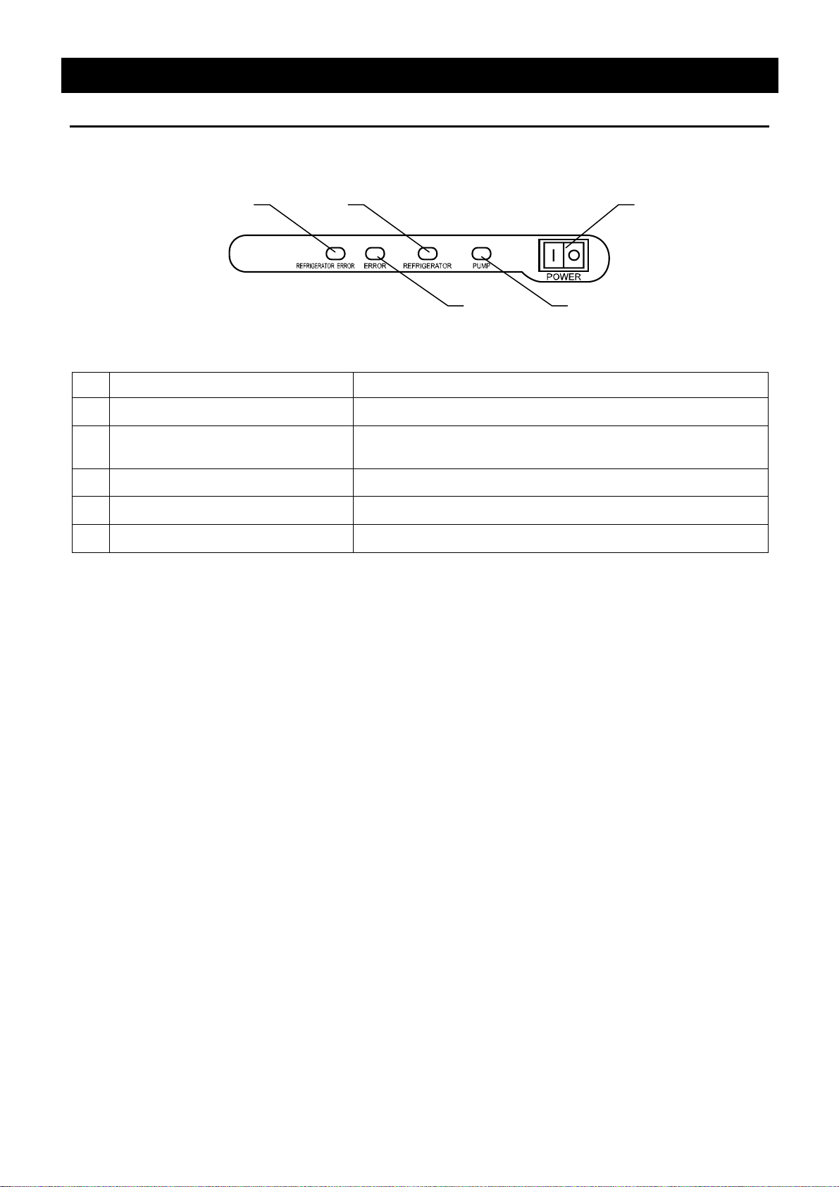
Operation Monitor
No. Name Function
REFRIGERATOR ERROR Lamp Lights when the refrigerator is over-lorded.
①
① ③
② ④
⑤
ERROR Lamp Lights when abnormality is found with the Temperature
②
adjuster.
REFRIGERATOR Lamp Lights when the refrigerator is running.
③
PUMP Lamp Lights when the pump is running.
④
POWER Switch Executes Power ON/OFF.
⑤
11

Description and Function of Each Part
Characters of the Controller
The characters controller shows are as follows:
Character Identifier Name Purpose
AStP
AStr
End
cAL
LocK
Pon
Accm
Refer to Page 15 "Operation Mode, Function Setting Key, and Characters" for operation mode and function
character.
Auto Stop Setting
Auto Start Setting
Time-up
Calibration Offset
Setting
Key Lock
Power failure
compensation setup
Addition time
Used for setting the auto stop operation.
Used for setting the auto start operation.
Displayed when timer operation is ended.
Used for inputting the calibration offset
temperature.
(Refer to Page 26 "Calibration Offset Function".)
Locks the keys on control panel to protect from
unnecessary operation.
(Refer to Page 27 "Lock Function".)
Used for Power failure compensation setup.
(Refer to Page 28 "Power Failure Compensation
Function".)
Displays the time that electricity is turned on with
the controller.
(Refer to Page 29 "Addition Time Function".)
12

Operation Mode and Function List
The operation modes of this unit are as follows;
Name Description Page
Operation Method
Fixed Temperature Operation
Quick Auto Stop Operation
Auto Stop Operation
Auto Start Operation
NOTE) This unit is impossible to be changed the mode during the operation. If the mode requires to be
changed, stop the operation.
Set the Temperature by ▼▲ key.
Start/Stop operation by pressing RUN/STOP key.
Used in case that the operation needs to be stopped a few
hours after setting.
The time to the operation stop can be set up by pressing
TIMER key during the Fixed Temp. operation.
The time can be set by ▼▲ key.
Auto Start operation will start by pressing RUN/STOP key.
Used for Auto Stop operation setting at the time of Fixed Temp.
operation setting.
The temperature can be set by ▼▲ key.
Display "AStP" by pressing TIMER key.
The time can be set by ▼▲ key.
Auto Stop operation will start by pressing RUN/STOP key.
Used for the operation that starts automatically a few hours
after turning on the POWER key.
The temperature can be set by ▼▲ key.
Display "AStP" by pressing TIMER key.
The time can be set by ▼▲ key.
Auto Start operation will start by pressing RUN/STOP key.
16
18
20
23
13

Operation Mode and Function List
The operation functions of this unit are as follows;
Name Description Page
This calibration offset function is for calibrating the
difference occurred between the required in- bath
Calibration offset function
temperature and control temperature (sensor
temperature) of the controller. This unit can be
calibrated toward either plus side or minus side of
the whole temperature range.
Operation Method
26
Setting value locking
Power failure compensation function
Addition time function
Temperature Output Terminal
This function locks the established operation status.
It can be set and cancelled with the SUB MENU key.
In case of electric outage during operation, the
operation will be started in the state just before the
electric outage.
It can be set or cancelled by SUB MENU key.
Time length while the Power supply is turned on is to
be added by 1 hour cycle.
It can be displayed by SUB MENU key.
Transmits and outputs the measured temperature of
the controller at 4 to 20 mA.
27
28
29
30
14

Operation Method
Operation Mode, Function Setting Key, and Characters
The operation mode setting and function setting use the key operation and characters show in the
following figure.
Breaker
ON
POWER switch
ON
Fixed Temp.
operation
Temperature
setting
1 sec.
/
operation
▲
RUN
STOP
Start
▲
Quick Auto Stop
Condition in which
it reached set ting
temperature
TIMER
Time setting
▲
▲
RUN
/
STOP
Timer start
End
Stop controllin g
automatically
RUN
1 sec.
/
STOP
Stop
operation
Timer
operation
Auto Stop
Temperature
setting
▲
▲
TIMER TIMER
AStP
Time setting
▲
▲
RUN
1 sec.
STOP
/
Start
operation
Timer start
after reaching
setting temperature
End
Stop controlling
automatically
Auto Start
Temperature
setting
AStr
Time setting
RUN
1 sec.
STOP
/
Timer start
Start operation
automatically
RUN
1 sec.
STOP
/
Stop
operation
▲
▲
▲
▲
Function
setting
SUB
4 sec.
MENU
SUB
MENU
Calibration offset
function
cAL
RUN
/
STOP
Offset temperature
setting
▲
Minus
SUB
4 sec.
MENU
Setting value lock
Lock setting
Plus OFF ON
▲
4 sec.
function
LocK
RUN
/
STOP
▲
SUB
MENU
▲
Power failure
compensation function
Pon
RUN
/
STOP
Power failu re
compensation setting
▲
OFF ON
4 sec.
SUB
MENU
▲
Addition time
function
Accm
/
Addition time
display
4 sec.
MENU
RUN
STOP
SUB
RUN
1 sec.
STOP
/
Stop
operation
15

Operation Method
Fixed Temperature Operation
In this mode, the unit starts to operate by pressing RUN/STOP key and continues operating at the set
temperature until RUN/STOP key is re-pressed, as shown in the figure below.
温度(℃)
TEMP.
SV:温度設定値
SV: Set Temp.
SV
時間(t)
スタート/ストップ キーON スタート/ストップ キーOFF
RUN/STOP key: ON RUN/STOP key: OFF
TIME
Fixed temperature
operation procedure
1. Turn on the earth leakage breaker/ POWER switch
• When the earth leakage breaker and POWER switch are turned
on, a starting screen will be displayed for about 4 seconds.
PUMP lamp is to be lit, the pump starts operating, and the
circulation starts. After starting operation, the initial setting
screen will be displayed. Each screen shows the current inner
bath temperature and setting temperature.
Measurement temperature screen:
Displays the current temperature in bath.
Setting temperature screen:
Displays the setting temperature.
2. Set the temperature
• Set the proper temperature by ▼▲ key.
The setting value will be smaller by ▼ key, and larger by ▲
key.
• Setting value will blink at the setting temperature screen.
16

Fixed Temperature Operation
3. Start operation
• Press RUN/STOP key for a second.
• FIXED TEMP. lamp will be lit and operation will start.
• When the refrigerator starts operating, REFRIGERATOR lamp
Operation Method
will be lit.
4. Stop operation
• Press RUN/STOP key for a second.
• FIXED TEMP. lamp will be put out and operation will stop.
• The screen will return to the initial setting screen.
To correct or check setting…
To change the setting value, press ▼▲ key. The blink will stop after 3 seconds, and the change will be
confirmed.
17

Quick Auto Stop Operation
Operation Method
Quick auto stop
operation procedure
This operation is used to specify the period up to automatic stop, i.e.,
sets the auto stop timer during operation.
1. Enter the quick auto stop mode during fixed temperature
operation
• Confirm that the FIXED TEMP. lamp is lit, and it is under
operation.
• Press TIMER key.
• AUTO STOP lamp will blink.
2. Set the timer
• Setting value will blink at setting temperature screen.
• Set the proper time by ▼▲ key.
The setting value will be smaller by ▼ key, and larger by ▲
key.
Timer function:
• The maximum setting time is "999 hours and 50 minutes".
• The time can be set in increments of a minute under 99 hours
and 59 minutes.
• It can be set in increment of ten minutes over 100 hours.
• The "▼▲" can change the setting time quickly when it is pressed
continuously. Press them discontinuously when fine adjustment
is needed.
3. Start timer operation
• Press RUN/STOP key.
• Start timer operation with the FIXED TEMP. lamp and AUTO
STOP lamp on.
• Timer operation starts when RUN/STOP key is pressed.
• Remaining time is displayed at the setting temperature screen
during the operation.
18

Quick Auto Stop Operation
4. Stop/terminate timer operation
• The operation will be stopped automatically at the setting time.
• The character "End" which tells that the operation is ended will
• End the timer operation mode by pressing RUN/STOP key for a
• The screen will return to initial setting screen.
Operation Method
blink at the setting temperature screen, while FIXED TEMP. lamp
and AUTO STOP lamp are on.
second.
5. To suspend quick auto stop operation
• End timer operation mode by pressing RUN/STOP key for a
second.
• The screen will return to initial setting screen.
To change the setting time…
To change the setting time during the operation, press TIMER key and set the proper time by ▼▲ key.
In this case, it is necessary to add the value of elapsed time to newly adding time. After a while, the blink
at the setting temperature screen will stop, and the change will be confirmed.
19

Operation Method
Auto Stop Operation
In this mode, the unit automatically comes to a stop after the set period passes away from the start of
fixed-value operation according to timer setting, as shown in the figure below.
TEMP.
温度(℃)
PV
SV:温度設定値
SV: Set Temp.
PV:温度表示値
PV: Current Temp.
SV
時間(t)
Timer Operation
RUN/STOP key: ON RUN/STOP key: OFF
スタート/ストップ キーON スタート/ストップ キーOFF
タイマスタート タイムアップ
Timer starts Time-up
タイマ起動
TIME
Auto stop operation
procedure
1. Turn on the earth leakage breaker/ POWER switch
• When the earth leakage breaker and POWER switch are turned
on, a starting screen will be displayed for about 4 seconds.
PUMP lamp is to be lit, the pump starts operating, and the
circulation starts. After starting operation, the initial setting
screen will be displayed. Each screen shows the current inner
bath temperature and setting temperature.
Measurement temperature screen:
Displays the current temperature in bath.
Setting temperature screen:
Displays the setting temperature.
2. Set the temperature
• Set the proper temperature by ▼▲ key.
The setting value will be smaller by ▼ key, and larger by ▲
key.
• Setting value will blink at the setting temperature screen.
Before the timer starts, the setting temperature can be changed
during the operation. Press ▼▲ key to change the setting
value. After 3 seconds from changing, the blink stops and the
change will be confirmed.
20

Auto Stop Operation
Operation Method
3. Select auto stop operation
• Press TIMER key, and display the character "AStP" which means
auto stop operation.
• Measured temperature screen:
"AStP" which means auto stop operation is displayed.
• Setting temperature screen:
The time which is set just before is displayed.
Timer function:
4. Set the timer
• Setting value will blink at setting temperature screen.
• Set the proper time by ▼▲ key.
The setting value will be smaller by ▼ key, and larger by ▲
key.
• The maximum setting time is "999 hours and 50 minutes".
• The time can be set in increments of a minute under 99 hours
and 59 minutes.
• It can be set in increment of ten minutes over 100 hours.
• The "▼▲" can change the setting time quickly when it is pressed
continuously. Press them discontinuously when fine adjustment
is needed.
5. Start timer operation
• Press RUN/STOP key for a second.
• AUTO STOP lamp blinks and the operation will start.
• Timer operation starts when the inner bath temperature at the
measured temperature screen reaches the setting temperature.
• During timer operation, the remaining time is displayed at the
setting temperature screen.
21

Auto Stop Operation
Operation Method
6. Stop/terminate timer operation
• The operation will be stopped automatically at the setting time.
• The character "End" which tells that the operation is ended will
blink at the setting temperature screen, while AUTO STOP lamp
is on.
• End the timer operation mode by pressing RUN/STOP key for a
second.
• The screen will return to initial setting screen.
7. To suspend auto stop operation
• End timer operation mode by pressing RUN/STOP key for a
second.
• The screen will return to initial setting screen.
To change the setting time…
To change setting time before the timer operation, press TIMER key. It will be in setting mode, and setting
time can be changed. Input time length from the time that it reaches the setting time to the time that it stops
the operation.
To change setting time before the timer operation, press TIMER key. In this case, it is necessary to add
the value of elapsed time to newly adding time.
After that, press RUN/STOP key to confirm the change.
22

Operation Method
Auto Start Operation
In this mode, the unit automatically starts to operate after the set period passes away from the start of
fixed temperature operation according to timer setting, as shown in the figure below. However, it does not
automatically come to a stop and must be manually deactivated.
温度(℃)
TEMP.
PV
SV:温度設定値
SV: Set Temp.
PV:温度表示値
PV: Current Temp.
SV
時間(t)
Timer Operation
タイマスタート
Timer starts Time-up
スタート/ストップ キーON スタート/ストップ キーOFF
RUN/STOP key: ON RUN/STOP key: OFF
タイマ起動 タイムアップ
TIME
Auto start operation
procedure
1. Turn on the earth leakage breaker/ POWER switch
• When the earth leakage breaker and POWER switch are turned
on, a starting screen will be displayed for about 4 seconds.
PUMP lamp is to be lit, the pump starts operating, and the
circulation starts. After starting operation, the initial setting
screen will be displayed. Each screen shows the current inner
bath temperature and setting temperature.
Measurement temperature screen:
Displays the current temperature in bath.
Setting temperature screen:
Displays the setting temperature.
2. Set the temperature
• Set the proper temperature by ▼▲ key.
The setting value will be smaller by ▼ key, and larger by ▲
key.
• Setting value will blink at the setting temperature screen.
Temperature can be changed during operation.
23

Auto Start Operation
Operation Method
3. Select auto start operation
• Press TIMER key, and display the character "AStr" which means
auto start operation.
• Measured temperature screen:
"AStr" which means auto start operation is displayed.
• Setting temperature screen:
The time which is set just before is displayed.
Timer function:
4. Set the timer
• Setting value will blink at setting temperature screen.
• Set the proper time by ▼▲ key.
The setting value will be smaller by ▼ key, and larger by ▲
key.
• The maximum setting time is "999 hours and 50 minutes".
• The time can be set in increments of a minute under 99 hours
and 59 minutes.
• It can be set in increment of ten minutes over 100 hours.
• The "▼▲" can change the setting time quickly when it is pressed
continuously. Press them discontinuously when fine adjustment
is needed.
5. Start timer operation
• Press RUN/STOP key for a second.
• AUTO START lamp blinks and the operation will start.
• During timer operation, the remaining time is displayed at the
setting temperature screen.
24

Auto Start Operation
Operation Method
6. Stop/terminate timer operation
• After timer operation, it will start operation at the setting time. At
this time, AUTO START lamp is still on.
• To stop/terminate timer operation, press RUN/STOP key for a
second, then timer operation mode will end.
• The screen will return to the initial screen.
7. To suspend auto start operation
• End timer operation mode by pressing RUN/STOP key for a
second.
• The screen will return to initial setting screen.
To change the setting temperature / setting time…
To change setting temperature during operation, press ▼▲ key. The initial value blinks at setting
temperature screen, and setting temperature can be changed by ▼▲ key.
To change setting time during operation, press TIMER key. The initial value blinks at setting temperature
screen, and setting time can be changed by ▼▲ key.
After either change, the blink at setting temperature screen stops, and the setting is confirmed.
In this case, it is necessary to add the value of elapsed time to newly adding time.
Any setting changes after auto start time cannot be done. In this case, press RUN/STOP key to stop the
operation once, then reset from the beginning.
25

Operation Method
Calibration Offset Function
Calibration offset is a function which corrects the difference between the temperature in bath and that of
controller (sensor temperature) if arises. The function parallel corrects the difference either to the plus or
minus side within the whole temperature range of unit. The function can be set or cancelled by the SUB
MENU key. "0" is set at factory shipment.
Corrected temp. to minus side
③
④
③
④
① Start operation with the target setting temperature. Check the
temperature in bath with a thermograph after it is stabilized.
② Check the difference between the setting temperature and that in
bath.
③ Press SUB MENU key for 4 seconds. Press SUB MENU key again.
Select "cAL" which means calibration offset, and press RUN/STOP
key.
④ Input the difference between setting temperature and inner bath
temperature by ▼▲ key, and press SUB MENU key for a few
seconds to complete the setting.
When the offset correction temperature is set to the minus side, the
temperature on the measurement temperature display screen falls by
the setting temperature, while the temperature on bath rises.
When it is set to the minus side, the temperature on the measurement
temperature display screen rises by the setting temperature, while the
temperature on bath falls.
The unit has two-point correction function, which performs offset
between low-temperature zone and high-temperature zone.
Please consult our local branch office when carrying out validation of
temperature controller.
Current temperature
Corrected temp. to plus side
26

Lock Function
Lock function that makes operation setting unchangeable.
① Press SUB MENU key for 4 seconds.
Then by pressing SUB MENU key, select the character "LocK" which
means setting value lock, and press RUN/STOP key.
Operation Method
② The display "oFF" will light at the setting temperature screen. By
changing the display to "on" with ▼▲ key, the setting value will be
locked.
Press SUB MENU key for a few seconds to complete the setting.
③ To cancel the lock function, press SUB MENU key for 4 seconds.
Then by pressing SUB MENU key, select the character "LocK" which
means setting value lock, and press RUN/STOP key.
④ Select "oFF" by ▼▲ key, and press RUN/STOP key to cancel the
lock function.
All keys other than the RUN/STOP and SUB MENU keys are lock when
the lock function is on.
27

Operation Method
Power Failure Compensation Function
This is the setting that can start the operation with the former setting in case of electric outage.
① Press SUB MENU key for 4 seconds.
Then by pressing SUB MENU key, select the character "Pon" which
means power failure compensation, and press RUN/STOP key.
② The display "oFF" will light at the setting temperature screen. By
changing the display to "on", power failure compensation operation is
set.
Press SUB MENU key for a few seconds to complete the setting.
③ To cancel power failure compensation, press SUB MENU key for 4
seconds.
Then select the character "Pon" by pressing SUB MENU key, and
press RUN/STOP key.
④ Select "oFF" by ▼▲ key, and press RUN/STOP key to cancel the
lock function.
28

Addition Time Function
Displays the time length that the controller is plugged.
① Press SUB MENU key for 4 seconds.
Then by pressing SUB MENU key, select the character "Accm" which
means addition time, and press RUN/STOP key.
Operation Method
② The time length that the controller is plugged is displayed at the
setting temperature screen.
Press SUB MENU key for a few seconds. The screen will returns to
the initial screen.
29

Te mperature Output Terminal
Precautions
• Operate this product according to the procedure described in this instruction manual. Failure
to follow the operation procedure described herein may result in a problem. The guarantee will
not apply if you operate the product in the wrong manner.
CAUTION!
• Turn off the breaker before connecting the cables.
• Connect a recorder or another appliance of 600 W or less in input impedance to the
temperature output terminal.
• Securely fasten all connections with the screws attached to the terminal block.
Operation Method
Connection procedure
• Connect the cables to the appropriate terminals.
• When using temperature output, use a shielded wire for the cable to be connected to prevent
noise.
ANALOG
+-
Connection terminal
30

Te mperature Output Terminal
Specification
• The voltage (DC) corresponding to the measured temperature is output.
• Output temperature range: CLS301 -15 to 35℃, CLS400/600 -20 to 35℃
Temperature Output
(ANALOG)
CLS301
• Output voltage: 4 to 20mA DC
• Load: 600Ω or bellow
• Resolution: ±1℃
• Connection: M4 screw terminal block
Operation Method
Temperature Output
35
22.5
10
Temp.
-2.5
-15
4 8 12 16 20
Output Voltage (mA)
CLS400/600
Temperature Output
35
21.25
7.5
Temp.
-6.25
-20
4 8 12 16 20
Output Voltage (mA)
31

y
y
Cooling curve, cooling capacity curve (reference data)
The graphs show the cooling and cooling capacity curves of each model below. Use the values
just for reference because they depend on the sample volume, the ambient temperature, etc.
CLS301 heating and cooling curves at a room temperature of 20°C
30.0
CLS300冷却曲線 室温20℃
Operation Method
20.0
10.0
温度(℃)
0.0
Temperature (°C)
-10.0
-20.0
0 30 60 90 120
Fluid quantity in external water tank:
外部槽液量 エチレングリコール50%5L
5 litters of eth
lene glycol 50%
Fluid quantity in external water tank:
外部槽液量 エチレングリコール50%10L
10 litters of eth
Elapsed time (minutes)
経過時間(分)
lene glycol 50%
CLS301/CLH301 Flow rate and head
CLS300/CLH300流量楊程
5.5
5
4.5
60Hz
4
3.5
3
2.5
Head (m)
楊程(m)
2
50Hz
1.5
1
0.5
0
0 0.5 1 1.5 2 2.5 3 3.5 4 4.5 5 5.5 6 6.5 7
Flow rate (L/min)
流量(L/min)
32

y
y
y
Cooling curve, cooling capacity curve (reference data)
CLS400 heating and cooling curves at a room temperature of 20°C
30.0
CLS400冷却曲線 室温20℃
Operation Method
20.0
10.0
温度(℃)
0.0
Temperature (°C)
-10.0
-20.0
0 30 60 90 120
Fluid quantity in external water tank:
外部槽液量 エチレングリコール50%5L
5 litters of eth
CLS400/CLH400 Flow rate and head
lene glycol 50%
Fluid quantity in external water tank:
外部槽液量 エチレングリコール50%10L
10 litters of eth
Elapsed time (minutes)
経過時間(分)
lene glycol 50%
CLS400/CLH400流量楊程
Fluid quantity in external water tank:
外部槽液量 エチレングリコール50%20L
20 litters of eth
lene glycol 50%
6.5
6
5.5
5
60Hz
4.5
4
3.5
3
Head (m)
楊程(m)
2.5
2
1.5
50Hz
1
0.5
0
0 0.5 1 1.5 2 2.5 3 3.5 4 4.5 5 5.5 6 6.5 7
Flow rate (L/min)
流量(L/min)
33

y
y
y
Cooling curve, cooling capacity curve (reference data)
CLS600 heating and cooling curves at a room temperature of 20°C
30.0
CLS600冷却曲線 室温20℃
Operation Method
20.0
10.0
温度(℃)
0.0
Temperature (°C)
-10.0
-20.0
0 30 60 90 120
Fluid quantity in external water tank:
外部槽液量 エチレングリコール50%10L
10 litters of eth
CLS600/CLH600 Flow rate and head
CLS600/CLH600流量楊程
lene glycol 50%
Fluid quantity in external water tank:
外部槽液量 エチレングリコール50%20L
20 litters of eth
Fluid quantity in external water tank:
外部槽液量 エチレングリコール50%30L
30 litters of eth
Elapsed time (minutes)
経過時間(分)
lene glycol 50%
lene glycol 50%
8.5
8
7.5
7
6.5
60Hz
6
5.5
5
4.5
4
Head (m)
楊程(m)
3.5
3
50Hz
2.5
2
1.5
1
0.5
0
0 0.5 1 1.5 2 2.5 3 3.5 4 4.5 5 5.5 6 6.5 7 7.5 8 8.5 9
Flow rate (L/min)
流量(L/min)
34

Cooling curve, cooling capacity curve (reference data)
CLS cooling capacity curves
1000
900
CLS600
800
CLS400
700
CLS冷却能力曲線
Operation Method
600
500
冷却能力(W)
400
Cooling capacity (W)
300
200
100
CLS300
CLS301
室温 :20℃
Room temperature: 20°C
使用循環液 :エチレングリコール50%
Used circulating fluid: Ethylene glycol 50%
外部水槽 :CTB-12A(12L)
External water tank: CTB-12A (12L)
電源 :AC100V 50Hz
Power supply: 100V AC 50Hz
0
-40 -30 -20 -10 0 10 20 30 40 50 60
Temperature (°C)
温度(℃)
35

Operation Method
Nybrine freezing temperature and viscosity (reference data)
Freezing temperatures of Nybrine Z1, Z1-K, and Nybrine NFP
ナイブラインZ1,Z1-KおよびナイブラインNFPの凍結温度
0
-10
凍結温度( ℃)
-20
Nybrine Z1, Z1-K
ナイブラインZ1,Z1-K
ナイブラインNFP
Nybrine NFP
-30
0
-10
-20
-30
Freezing temperature (°C)
-40
-50
0 102030405060708090100
Nybrine concentration (wt%)
ナイブライン濃度(wt%)
-40
-50
Viscosity of Nybrine Z1, Z1-K, and RH aqueous solution)
ナイブラインZ1,Z1-K,RH水溶液の粘度
粘
度(
m
P
a
・
s
e
c
)
Viscosity (mPa・sec)
1000
800
600
400
200
Freezing
100
80
60
40
20
10
8
6
4
2
1
0.8
0.6
0.4
凍結
Freezing
凍結
Freezing
凍結
Freezing
凍結
Freezing
Freezing
Kinetic viscosity = Viscosity/Specific gravity
1 cSt = 1 mPa·sec/d
Freezing
凍結
凍結
Freezing
凍結
動粘度=粘度/比重
1cSt=1mPa・sec/d
1
0
0
%
8
0
%
7
0
%
6
0
%
5
0
%
4
0
%
3
0
%
2
0
%
0
%
-40 -20 0
Temperature (°C)
36
40 60 80 100
20
温 度(℃)

Handling Precautions
WARNING!
If a problem occurs
If smoke or strange odor should come out of this unit for some reason, turn off the POWER
switch right away, and then turn off the circuit breaker and the main power. Immediately contact
a service technician for inspection. If this procedure is not followed, fire or electrical shock may
result. Never perform repair work yourself, since it is dangerous and not recommended.
Substances that cannot be used
Never use explosive substances, flammable substances and substances that include explosive
or flammable ingredients in this unit. Explosion or fire may occur. (Refer to page 50 "List of
Dangerous Substances".)
CAUTION!
Do not step on this unit
Do not step on this unit. It will cause injury if this unit fall down or break.
Do not put anything on this unit
Do not put anything on this unit. It will cause injury if fall.
During a thunder storm
During a thunderstorm, turn off the POWER switch immediately, then turn off the circuit breaker
and the main power. If this procedure is not followed, fire or electrical shock may be caused.
Thoroughly wash the unit.
The unit was washed already. However, when you first use it or operate it after a long period of
deactivation, thoroughly wash it.
Circulating fluid to be used in the external water tank
For the circulating fluid to be used in the external water tank, use an aqueous solution of
ethylene glycol 50% (Vol %) or Nybrine
®
40% (Vol %).
Resupply of ethylene glycol and Nybrine®
Ethylene glycol or Nybrine® gradually varies in density when used. If the solution is used with its
concentration lower than the appropriate level, it may freeze or its viscosity may increase, which
may result in pump malfunction. Additionally, if ethylene glycol or Nybrine
panel, wipe it out. Electric leakage or electric shock may result.
The circulating pump protection
• Do not let the citculating pump run at idle. This may result in the circulating pump malfunction.
• Entering foreign materials into the cooler may result in damage of the circulating pump.
• When installing a solenoid valve or a throttle valve in the circulating route, do not close or
extremely squeeze it for protection of the circulating pump.
• Secure the flow amount of 1.5L/min or more for the circulating fluid.
®
gets on the control
37

Handling Precautions
Countermeasure for stop operation during night or long-term stop
In case of stopping operation during night or long-term, toggle the breaker and POWER switch to
"OFF".
Recovery from a power failure
If the unit was deactivated in the middle of operation due to a power failure and is re-energized,
the unit automatically returns to the state just before the power failure and resumes operation.
If the resumption of operation by automatic recovery is inconvenient, turn off the leakage
breaker.
Abnormal refrigerator pressure
If the refrigerator operates in a high-temperature range, the refrigerator overload relay protecting
circuit may work to illuminate REFRIGERATOR ERROR lamp deactivate the refrigerator.
In this case, reduce thermal load by changing the fluid, or taking other appropriate measures.
38

Maintenance Method
Daily Inspection and Maintenance
For the safety use of this unit, please perform the daily inspection and maintenance without fail.
Using the city water to this unit might attach dirt. Do inspect and maintain this point while performing
daily inspection and maintenance.
WARNING!
• Disconnect the power cable from the power source when doing an inspection or maintenance
unless needed.
• Perform the daily inspection and maintenance after returning the temperature of this unit to the
normal one.
• Do not disassemble this unit.
CAUTION!
• Use a well-drained soft cloth to wipe dirt on this unit. Do not use benzene, thinner or cleanser for
wiping. Do not scrub this unit. Deformation, deterioration or color change may result in.
Monthly maintenance
• Check the earth leakage breaker function.
1. Connect the power cord.
2. Turn the breaker on.
3. Push the red test switch by a ballpoint pen etc.
4. If there is no problem, the earth leakage breaker will be turned off.
Maintaining the external water tank
• Remove foreign substances inside the external water tank as frequently as possible. They may
result in circulating pump malfunction if they are left there.
Replacing the hoses
• Replace the hoses at regular intervals, ideally every two years, to use the product in good
condition. Ask Yamato Scientific Co., Ltd. for replacement.
39

Daily Inspection and Maintenance
Cleaning the filter
Maintenance Method
The mesh plate is fixed with a magnet. Pull it toward
you.
The bottom of the mesh plate is slipped over pins. Lift
it up and remove it.
The filter cover is fixed with a magnet. Remove it, and
clean the filter or remove dust with a vacuum cleaner.
Deep inside the filter is a condenser fin. Do not touch
it with bare hands because you may get injured.
After cleaning, reversely follow the procedure to
replace the filter cover.
For any questions, contact the dealer who you purchased this unit from, or the nearest sales
division in our company.
40

Long storage and disposal
When not using this unit for long term / When disposing
CAUTION!
When not using this unit for long term…
• Turn off the breaker and disconnect the power cord.
WARNING!
When disposing…
• Keep out of reach of children.
• The unit uses a CFCs substitute. Ask a qualified disposal service company for the disposal of it.
Environmental protection should be considered
We request you to disassemble this unit as possible and recycle the reusable parts considering to the
environmental protection. The feature components of this unit and materials used are listed below.
Component Name Material
Exterior Parts
Outer covering Iron steel plate
Inner bath Stainless steel SUS304
Plates PET resin film
Brace Aluminum
Rubber vibration insulator Chloroprene rubber
Electrical Parts
Switches, Relays Composite of resin, copper and other
Circuit boards Composite of glass fiber and other
Power cord Composite of synthetic rubber, copper and nickel
Piping Parts
Hoses Silicon rubber, EPDM
Joints Brass, Stainless steel
Hose clamp 66 nylon
Hose nipple Brass
41

In the Event of Failure…
Safety Device and Error Code
This unit has an automatic diagnosis function built in the controller and safety devices independent of the
controller. The table below shows the cause and the solution method when the safety device operates.
Error Code:
When an abnormal condition occurs, an error code appears and the ALARM lamp lights in the controller,
the buzzer sounds simultaneously. Record the error code and turn off the power of device
immediately.
Safety Device Notify Cause/Solution
• Failure in temperature input circuit.
• Temperature sensor is broken or
Temperature input error
“ALARM” lamp lights on,
“Er.01” appears
disconnected.
• Measured temperature is out of display
range.
Make a call for service.
Memory error
Flow rate error
Measurement temperature
error
Refrigerator pressure error
“ALARM” lamp lights on,
“Er.15” appears
“ALARM” lamp lights on,
“Er.20” appears
“ALARM” lamp lights on,
“----” appears
“REFRIGERATO ERROR”
lamp lights on
• Failure in internal memory.
Make a call for service.
• The circulating fluid does not properly
circulate.
• Air remains in the circulating path.
Make a call for service.
• Upper limit alarm of the temperature
alarm function is activated.
Make a call for service.
• The condenser filter is dirty.
• The room temperature is high.
Make a call for service.
42

Trouble Shooting
Phenomenon Check point
In the Event of Failure…
The unit does not start to
operate although the earth
leakage breaker and POWER
switch are turned on.
The ALARM lamp lights on.
The temperature does not drop.
The circulating pump produces
unusual noise.
The circulating fluid does not
circulate.
"REFRIGERATO ERROR" lamp
lights on.
• Check if the power cable is securely connected to the power
supply.
• Check if the power fails.
• Check if the external water tank is filled with a circulating fluid.
• Check if the set temperature is higher than the inside
temperature of the bath.
• Check if the condenser filter is contaminated.
• Check if air remains in the circulating pump.
Turn off the power, and open the air release valve in the back of the
system to let out air.
• Check if the insulation hose with a priming pump is properly
connected. (Refer to page 7.)
• Check if the quantity of fluid inside the external water tank is
sufficient.
• Operate the priming pump more frequently and retry.
• Check if the condenser filter is dirty.
• Check if the room temperature is high.
The displayed temperature does
not match the measured
temperature.
• Check if the set value of calibration offset is other than "0". Set
it at "0". (Refer to page 26.)
When a power failure occur
If the unit was deactivated in the middle of operation due to a power failure and is re-energized, the unit
automatically returns to the state just before the power failure and resumes operation. (To know the
setting method of this function, refer to page 28 "Power Failure Compensation Function".)
If the resumption of operation by automatic recovery is inconvenient, turn off the leakage breaker.
In the case if the error other than listed above occurred, turn off the POWER switch and primary
power source immediately. Contact the shop of your purchase or nearest Yamato Scientific
Service Office.
43

After Service and Warranty
In Case of Request for Repair
If the failure occurs, stop the operation, turn OFF the POWER switch, and unplug the power
plug. Please contact the sales agency that this unit was purchased, or the Yamato Scientific's
sales office.
< Check following items before contact >
◆ Model Name of Product
◆ Production Number
◆ Purchase Date
◆ About Trouble (in detail as possible)
Minimum Retention Period of Performance Parts for Repair
The minimum retention period of performance parts for repair of this unit is 7 years after
discontinuance of this unit.
The "performance part for repair" is the part that is required to maintain this unit.
See the production plate attached to this unit.
44

Specification
Product Name Coolline
Model CLS301 CLS400 CLS600
Circulation unit Circulation in the external open system
Usable ambient temp.
Temperature control range
Temperature setting range
Temperature adjustment
accuracy
Refrigerator
Maximum flow rate of pump
Performance
(50/60 Hz)
Maximum head of pump
(50/60 Hz)
Bath SUS304
Temperature control method Refrigerator ON-OFF control
Sensor T-thermocouple
Temperature setting method Digital setting by up/down keys
Display method Digital display
Refrigerator
Configurations
Cooling medium HFC R404A 270g HFC R404A 370g HFC R404A 475g
Cooling coil Copper
Outside diameter of
external circulating nozzle
Circulation pump Magnet pump 20W Magnet pump 45W
Safety devices
Approx.450W at15℃ Approx.570W at15℃ Approx.820W at15℃
200W 350W 600W
Both discharge and return ports: φ13 hose nipple
Over current earth leakage breaker, Refrigerator overload relay protecting
circuit, Pump thermal protector (Pump built-in), Refrigerator pressure
detection, Delay timer for refrigerator protection, Bypass for circulating
pump protection, Dustproof filter for condenser, Key lock Function
-10℃ to Room temperature
10/11 L/min 15/17 L/min
4.9/6.9m 8/11m
5 to 30℃
-15 to 35℃
±1.5 to 2.0℃
Air-cooled rotary
Other functions Operation monitor, Drain cock, Temperature output terminal
Bath dimensions
(Inner dia.×height)
External dimensions
(W×D×H)
Bath capacity 1.5L 3L
Standard
Power supply (50/60Hz) 100V AC, 4A 100V AC, 6A 100V AC, 10A
Weight Approx. 40kg Approx. 45kg Approx. 60kg
Optional accessories
φ120×200 mm φ150×200 mm
380×460×500 mm 380×460×720 mm 380×565×720 mm
1-meter-long insulation hose: 1, 1-meter-long insulation hose with a
priming pump: 1, Drain hose 0.5m: 1, Wire clamp: 4, Instruction manual
45

CLS301
ELB
Wiring Diagram
T1
AC100V
PSW
TH
2
1
X3-1
X2
X2
3
P
4
5
PS
FS
X4-2
21
X3-2
X1
X4
X3
6
X5
X1
C1
C2
X5
RF
FM
OVR
T2
1
3
1
C
3
S
2
R
2
3
4
Symbol Part name Symbol Part name
ELB Earth leakage breaker C2 Start condenser
T1 Terminal block X5 Start relay
T2 Terminal block WIB Operation display board
T3 Terminal block PSW Power switch
PLB PLANAR board P Magnet pump
PIO Display board X1 Relay (refrigerator)
TH Temperature sensor (T) X2 Relay (error)
FM Fan motor X3 Relay (pressure)
RF Compressor X4 Relay (flow)
OVR Overload relay PS Pressure switch
C1 Operation condenser FS Flow sensor
X4-1
1
+
2
3
-
4
5
TB1
6
7
8
9
10
11
12
13
14
TB2
15
16
17
1
CN1
20
PLB
T3
+
1
PV transmission output
PV伝送出力(4-20mA)
-
2
1
2
CN1
3
1
2
CN2
3
1
CN4
2
3
1
CN6
2
3
WIB
1
CN1
20
PIO
46

CLS400
ELB
Wiring Diagram
T1
AC100V
PSW
TH
2
1
X3-1
X2
X2
3
P
4
5
PS
FS
X4-2
X3-2
X1
X4
X3
6
X5
X1
C1
C2
X5
RF
FM
OVR
T2
1
3
1
C
3
S
2
R
2
3
4
Symbol Part name Symbol Part name
ELB Earth leakage breaker C2 Start condenser
T1 Terminal block X5 Start relay
T2 Terminal block WIB Operation display board
T3 Terminal block PSW Power switch
PLB PLANAR board P Magnet pump
PIO Display board X1 Relay (refrigerator)
TH Temperature sensor (T) X2 Relay (error)
FM Fan motor X3 Relay (pressure)
RF Compressor X4 Relay (flow)
OVR Overload relay PS Pressure switch
C1 Operation condenser FS Flow sensor
X4-1
1
+
2
3
-
4
5
TB1
6
7
8
9
10
11
12
13
14
TB2
15
16
17
1
CN1
20
PLB
T3
+
1
PV transmission output
PV伝送出力(4-20mA)
-
2
1
2
CN1
3
1
2
CN2
3
1
CN4
2
3
1
CN6
2
3
WIB
1
CN1
20
PIO
47

CLS600
ELB
Wiring Diagram
T1
AC100V
PSW
TH
2
1
X3-1
X2
X2
3
P
4
5
PS
FS
X4-2
X3-2
X4-1
X1
X4
X3
6
T2
X1
1
RF
FM
OVR
C
S
R
2
3
4
X5
C1
C2
X5
Symbol Part name Symbol Part name
ELB Earth leakage breaker C2 Start condenser
T1 Terminal block X5 Start relay
T2 Terminal block WIB Operation display board
T3 Terminal block PSW Power switch
PLB PLANAR board P Magnet pump
PIO Display board X1 Electromagnetic Contact(refrigerator)
TH Temperature sensor (T) X2 Relay (error)
FM Fan motor X3 Relay (pressure)
RF Compressor X4 Relay (flow)
OVR Overload relay PS Pressure switch
C1 Operation condenser FS Flow sensor
1
+
2
3
-
4
5
TB1
6
7
8
9
10
11
12
13
14
TB2
15
16
17
1
CN1
20
PLB
T3
+
1
PV transmission output
PV伝送出力(4-20mA)
-
2
1
2
CN1
3
1
2
CN2
3
1
CN4
2
3
1
CN6
2
3
WIB
1
CN1
20
PIO
48

Replacement Parts Table
Common Parts
Symbol Part Name Code No. Specification Manufacturer
WIB Operation display board LT00006042 Toho Denshi
PLB, PIO Temperature controller LT00005449 TTM-00B-YC (with tough card) Toho Denshi
FS Float switch LT00006043 NK-1RAN 1.2/min Nicom
TH Temperature sensor LT00005488 T-thermocouple L-50mm Yamato Scientific
- Flow rate adjusting valve LT00006065 6542-10 G3/8 Kakudai
- Air release valve LT00006067 TA295BH-29 Tasco
- Drain cock LT00005465 TA295BH-31 Tasco
PSW Power switch 2-01-001-0011 DS-850S-F2-10 Miyama
X2,3,4 Relay 2-05-000-0055 AP3524K Matsushita
T1 Terminal block LT00031663 TFD250ABC-6P Terminal
T2 Terminal block LT00031661 TFD250ABC-4P Terminal
T3 Terminal block LT00032123 W101A-2P World
ELB Earth leakage breaker LT00029774 NV-L22GR 15A Mitsubishi
- Power cord 2-13-001-0005 T2-3b Yamato Scientific
CLS301
Symbol Part Name Code No. Specification Manufacturer
P Magnet pump LT00005462 MD20RZ-N Iwaki
RF Compressor LT00005487 C-2SN200LOT Sanyo
FM Fan motor 3-01-006-006 SE4-CO41NP Sanyo
X1 Relay LT00012708 G4B-112T1 OMRON
CLS400
Symbol Part Name Code No. Specification Manufacturer
P Magnet pump LT00005462 MD20RZ-N Iwaki
RF Compressor 3-01-006-0005 C-2SN350LOR Sanyo
FM Fan motor 3-01-006-006 SE4-CO41NP Sanyo
X1 Relay LT00012708 G4B-112T1 OMRON
CLS600
Symbol Part Name Code No. Specification Manufacturer
P Magnet pump 2-15-008-0013 MD30RZ-N Iwaki
RF Compressor 3-01-006-0012 C-RHN60LOA Sanyo
FM Fan motor 3-01-006-0014 SE4-D11LP Sanyo
X1 Electromagnetic Contact LT00032906 FC-0ST 1a 100V Fuji
49

List of Dangerous Substances
Never use explosive substances, flammable substances and substances that include explosive
or flammable ingredients in this unit.
EXPLOSIVE
Ethylene glycol dinitrate (nitro glycol), Glycerin trinitrate (nitroglycerine), Cellulose
nitrate (nitrocellulose), and other explosive nitrate esters
Reference
EXPLOSIVE:
FLAMMABLE
IGNITING:
OXIDIZING:
Trinitrobenzene, Trinitrotoluene, Trinitrophenol (picric acid), and other explosive
nitro compounds
Acetyl hidroperoxide (peracetic acid), Methyl ethyl ketone peroxide, Benzyl
peroxide, and other organic peroxides
Lithium (metal), Potassium (metal), Sodium (metal), Yellow phosphorus,
Phosphorus sulfide, Red phosphorus, Celluloid compounds, Calcium carbide,
Lime phosphate, Magnesium (powder), Aluminum (powder), Powder of metals
other than magnesium and aluminum, Sodium hydrosulfite
Potassium chlorate, Sodium chlorate, Ammonium chlorate, and other chlorate
Potassium perchlorate, Sodium perchlorate, Ammonium perchlorate, and other
perchlorate
Potassium peroxide, Sodium peroxide, Barium peroxide, and other inorganic
peroxide
Potassium nitrate, Sodium nitrate, Ammonium nitrate, and other nitrate
Sodium chlorite and other chlorites
Calcium hypochlorite and other hypochlorites
Ethyl ether, Gasoline, Acetaldehyde, Propylene chloride, Carbon disulfide, and
other flammable substances having a flash point of lower than -30℃
INFLAMMABLE
LIQUID:
FLAMMABLE
GAS:
Normal hexane, ethylene oxide, acetone, benzene, methyl ethyl ketone, and
other flammable substances having a flash point of -30℃ or higher but lower
than 0℃
Methanol, Ethanol, Xylene, Pentyl acetate (amyl acetate), and other flammable
substances having a flash point of 0℃ or higher but lower than 30℃
Kerosene, Light oil (gas oil), Oil of turpentine, Isopentyl alcohol (isoamyl alcohol),
Acetic acid, and other flammable substances having a flash point of 30℃ or
higher but lower than 65℃
Hydrogen, Acetylene, Ethylene, Methane, Propane, Butane, and other flammable
substances which assume a gaseous state at 15℃ and 1 atm
(Source: Appendix Table 1 of Article 6 of the Industrial Safety and Health Order in Japan)
50

Installation Standard Manual
Install the unit according the procedure described below (check options and special specifications
separately).
Model Serial number Date
Person in charge of installation
(company name)
№
Specifications
1 Accessories
2 Installation
Operation
1 Power voltage
2
Description
1
2 Error code
3
4
Item Method Reference operation manual Judgment
Check the quantities of accessories with
Start of
operation
Description of
operation
Maintenance
inspection
Completion of
installation
Information to
be entered
the quantities shown in the Accessory
column.
・Visually check the surrounding area.
Caution: Pay attention to the ambient
environment.
・Keep space.
・Pour water into the water bath.
Caution: Air release.
・Using a tester, measure the voltage of
the voltage used by the customer
(distribution board, outlet, etc.).
・Measure the voltage during operation
(the voltage must be within the
standard).
Caution: When a unit is to be connected
to the plug or breaker, use one that
conforms to the standard.
・Start operation.
The circulating water must circulate.
Set the temperature at 20°C to confirm
the state.
Check: Water leakage is not permissible.
Explain the operation of each unit to the
customer according to this Operation
Manual.
Explain error codes and the procedure for
resetting them to the customer according
to this Operation Manual.
Explain the operation of each unit to the
customer according to this Operation
Manual.
・Enter the date of installation and the
name of the person in charge of
installation on the face plate on the
unit.
・ Enter necessary information on the
guarantee, and pass it to the customer.
・Explain the after-sale service route to
the customer.
Specification
Before Using This Unit
"2. Choose a proper place for
installation"
Before Using This Unit
"Installation Procedure"
Before Using This Unit
"1. Always ground this unit"
Before Using This Unit
"6. Choose a correct power
distribution board or receptacle"
Specification
Before Using This Unit
"Installation Procedure"
Operation Method
In the Event of Failure…
Maintenance Method
After Service and Warranty
Person in charge of
installation
P.45
P.45
P.13
All
P.42
P.39
P. 44
Judgment
P. 4
P. 7
P. 4
P. 5
P. 7
51

Responsibility
Please follow the instructions in this document when using this unit. Yamato Scientific has no
responsibility for the accidents or breakdown of device if it is used with a failure to comply.
Never conduct what this document forbids. Unexpected accidents or breakdown may result in.
Note
◆ The contents of this document may be changed in future without notice.
◆ Any books with missing pages or disorderly binding may be replaced.
Instruction Manual for
Coolline
Model CLS301/400/600
Third Edition Dec. 10, 2009
Yamato Scientific Co., Ltd.
2-1-6 Nihonbashi Honcho, Chuo-ku,
Tokyo, 103-8432, Japan
http://www.yamato-net.co.jp
52
 Loading...